

Page 1

ENGLISH
ENGLISH
PL12,13
INSTRUCTION MANUAL
Read safety instructions carefully and understand them before using.
Retain this Instruction Manual for future reference.
CAUTION
This Instruction Manual is intended for the PL12/PL13 To use this product when it is installed
on a machine (sewing machine), make sure to read and fully understand the “IMPORTANT
SAFETY INSTRUCTIONS” provided in the Instruction Manual for the machine on which this
product is to be installed in advance.
For a clearer view of the PL12/PL13 illustrations of the machine (sewing machine) are simplied.
Page 2

CONTENTS
1. SPECIFICATIONS .................................................................................... 1
2. ASSEMBLING THE REAR ROLLER ASM. .............................................1
3. ADJUSTING THE ROLLER PRESSER PRESSURE ..............................1
4. HOW TO USE THE MANUAL LEVER ..................................................... 2
5. ADJUSTING THE FEED AMOUNT OF THE ROLLER ............................ 2
6. FEED TIMING OF THE ROLLER ............................................................. 3
7.
ADJUSTING THE CLEARANCE BETWEEN THE GEAR ROLLERS (PL12)
8. ADJUSTING THE ROLLER PRESSER LIFTER .....................................4
9. ADJUSTING THE CLIUTCH TENSION SPRING ....................................4
10. LUBRICATION .........................................................................................5
.... 3
ENGLISH
i
Page 3
1. SPECIFICATIONS
Model PL 12 (Gear roller), PL 13 (Flat roller)
Class name Cloth puller device
Sewing speed Max. 5,000 sti/min (at the time of intermittent operation)
Speed of stitch at the delivery. 4,000 sti/min (at the time of intermittent operation)
Lift of roller Manual lever PL12 : 8.6mm , PL13 : 10.3mm
Presser lifter When lift of presser foot is 4 mm PL12 : 6.3 mm, PL13 : 8.0 mm
When lift of presser foot is 5 mm PL12 : 7.0 mm, PL13 : 8.7 mm
When lift of presser foot is 6 mm PL12 : 7.8 mm, PL13 : 9.5 mm
Presser pressure 50N to 150N
Feed amount 1.6 mm to 5.0 mm
Noise -
Equivalent continuous emission sound pressure level (LpA) at the workstation :
A-weighted value of 82.5 dB; (Includes KpA = 2.5 dB); according to ISO 10821- C.6.2 -ISO 11204 GR2 at 5,000 sti/min.
- Sound power level (LWA) ;
A-weighted value of 88.5 dB; (Includes KWA = 2.5 dB); according to ISO 10821- C.6.2 -ISO 3744 GR2 at 5,000 sti/min.
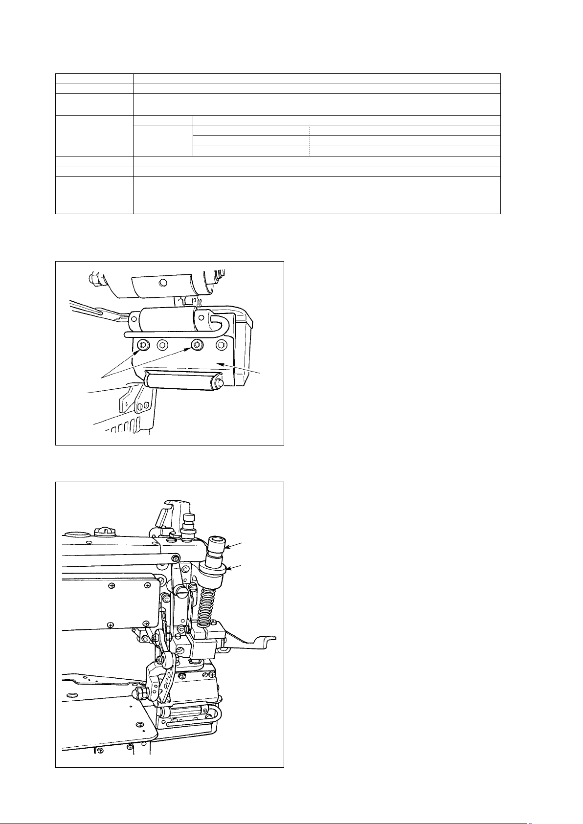
2. ASSEMBLING THE REAR ROLLER ASM.
Install rear roller asm. 2 which is contained in the acces-
sories with two screws 1.
1
2
3. ADJUSTING THE ROLLER PRESSER PRESSURE
Loosen nut 1, and turn presser spring regulator 2 to the
right (clockwise) when increasing the presser pressure.
Turn presser spring regulator 2 to the left (counterclock-
wise) when decreasing the presser pressure.
2
1
– 1 –
Page 4
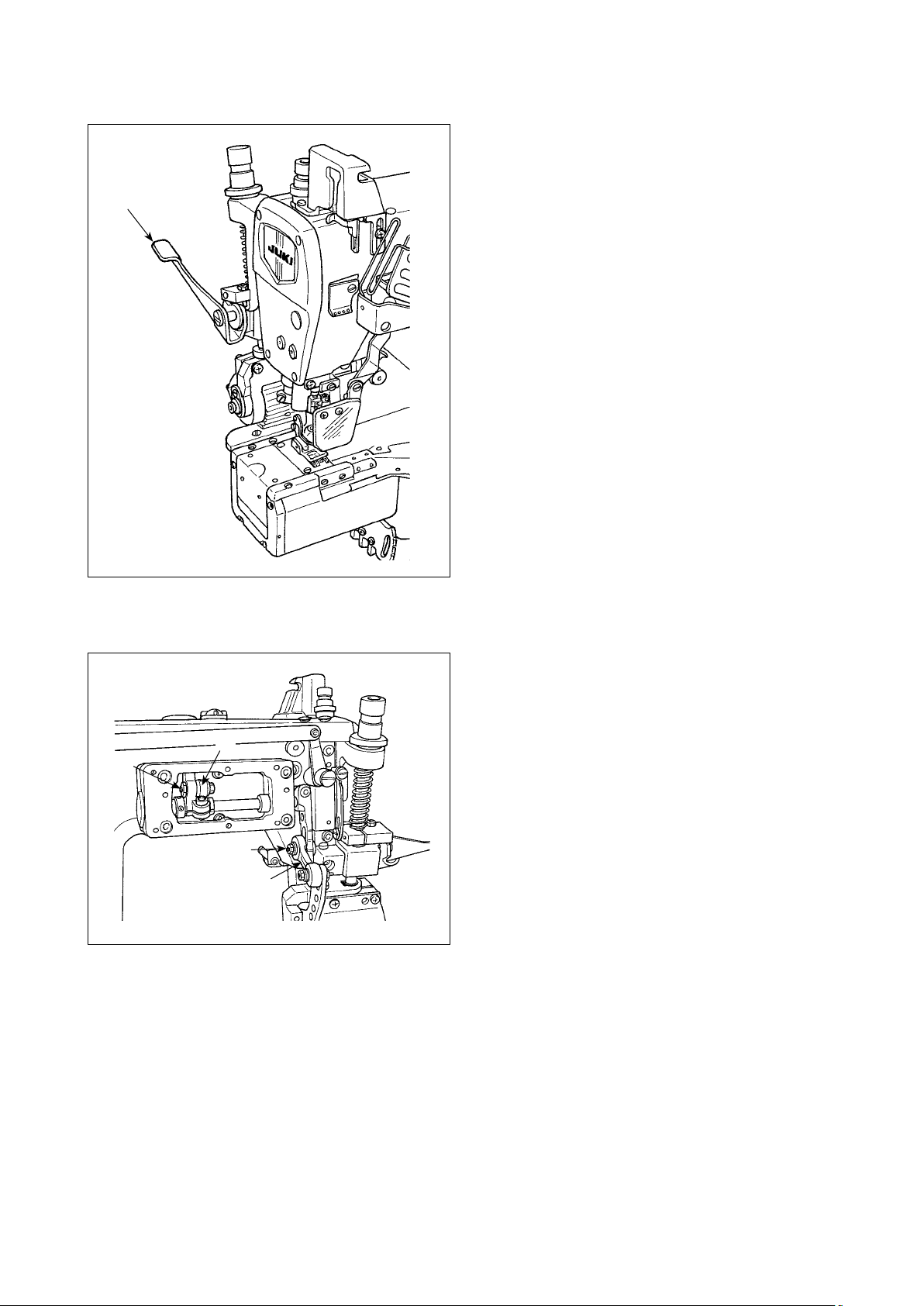
4. HOW TO USE THE MANUAL LEVER
1
Lift lever 1 when the cloth puller device is not used at the
time of performing setting of material or removing material
which has been sewn.
Lower lever 1 when sewing using the cloth puller device.
ENGLISH
5. ADJUSTING THE FEED AMOUNT OF THE ROLLER
Loosen screw 1 when adjusting the feed amount of the
roller. Feed amount is decreased when link 2 is lifted.
Feed amount is increased when link 2 is lowered.
When changing the feed amount further, loosen screw 3
4
3
1
2
to adjust. Feed amount is decreased when rod 4 is lifted.
Feed amount is increased when rod 4 is lowered.
– 2 –
Page 5
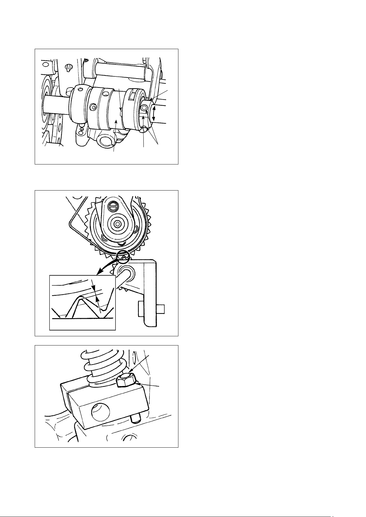
6. FEED TIMING OF THE ROLLER
Notch A in collar 3 aligns with notch B in the puller eccen-
tric cam when the roller is placed in the standard position.
When changing the feed timing, loosen two setscrews
in puller eccentric cam 1 to adjust. When the cam is
2
A
B
1
C
D
2
moved in the direction of C, the start of the roller is ad-
vanced, and when it is moved in the direction of D, the
start of the roller is delayed.
3
7. ADJUSTING THE CLEARANCE BETWEEN THE GEAR ROLLERS (PL12)
In case of the gear type roller, loosen nut 2 and adjust the
length of screw 1 so that the clearance between the top
and the bottom rollers is approximately 0.3 mm in the state
that the rollers are lowered.
0.3mm
1
2
– 3 –
Page 6
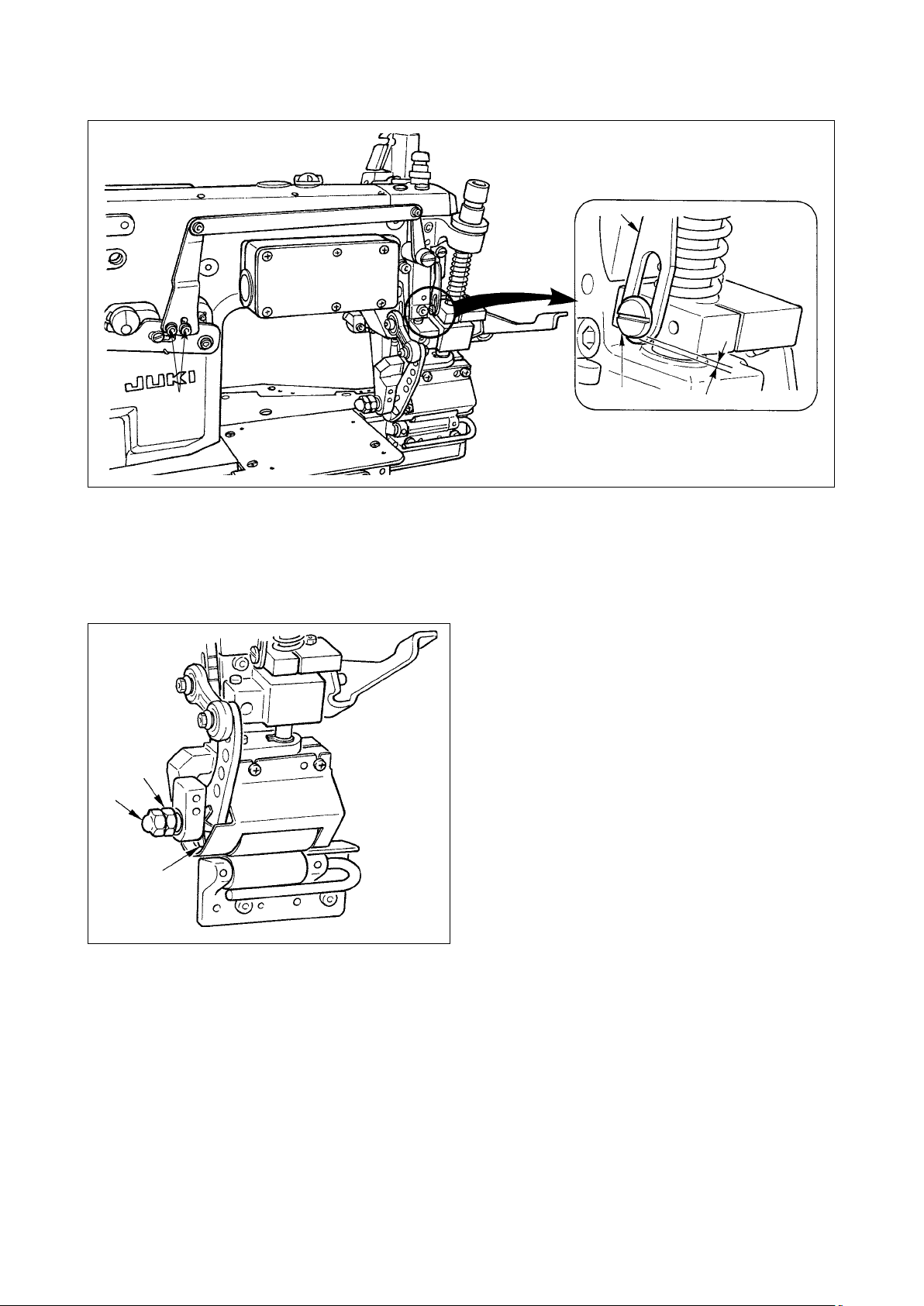
8. ADJUSTING THE ROLLER PRESSER LIFTER
2
ENGLISH
1
Adjust with two screws 1 so that the clearance between presser lifter lever link, short 2 and hinge screw 3 is 0.5 mm
when performing the presser lifting in the state that the top roller is lowered.
3
0.5mm
9. ADJUSTING THE CLIUTCH TENSION SPRING
Adjustment is performed with clutch tension spring 1 so
that the top roller does not overrun at high-speed rotation.
When performing the adjustment, loosen cap nut 2, and
turn nut 3 to the right (clockwise) to increase the spring
pressure. When decreasing the spring pressure, turn nut
to the left (counterclockwise).
3
After the adjustment, tighten cap nut 2.
3
2
(Note) The standard of the spring pressure is to such an
extent that clutch tension spring 1 turns with
the small force of your nger after tightening
cap nut 2.
1
– 4 –
Page 7
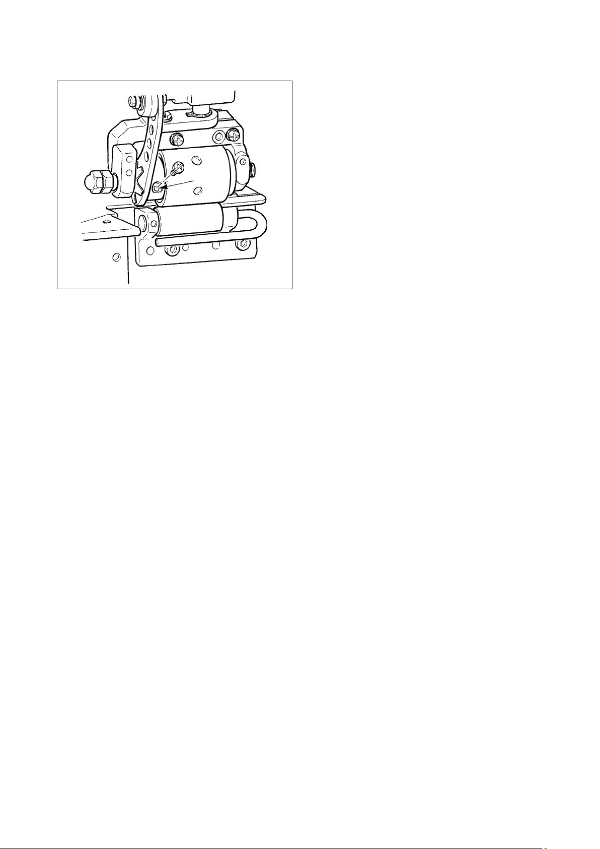
10. LUBRICATION
Periodically perform greasing once a year as the standard.
Use the exclusive grease supplied as the accessories.
Grease tube (Part No. 13525506)
•
Remove the upper roller cover, and remove the screw in
section A. Fully pour the grease supplied as the accesso-
ries out of the section A into the device. After pouring the
grease, install the screw and the upper roller cover.
A
– 5 –
 Loading...