

Page 1
POSITIONER
Technical
Manual
INSTALLATION
INSTRUCTION
TROUBLE
SERVICE
SHOOTING
PARTS
LIST
TOKYO JUKI INDUSTRIAL CO., LTD.
Page 2
TABLE
OF
CONTENTS
Subject
1 INTRODUCTION 1
2 FEATURES 1
3 MODEL AND TYPES 2
4 INSTALLATION 3
5 ELECTRICAL CONNECTIONS 4
6 OPERATION 5
7 MAINTENANCE 8
8 HOW TO CHECK THE DRIVE
9 DIMENSION
10 PARTS
LIST
UNIT
Page
13
15
16
Page 3
INTRQWCTION
This needle positioner represents a new
concept
in needle-positioning motor. This device
meets
all
requirements for control functions that may be needed in the future. It is controlled by an electronic
circuit which enables the
of the sewing machine
simply touching
1-1
Componentofthe
the
powerful
promptly.
pedal softly.
needle
electro-magnetic clutch and brake to increase and decrease the speed
Variations of the operational speed are stepless and accomplished by
positioner
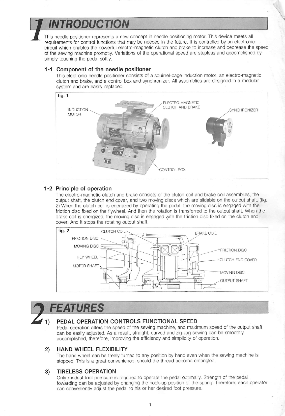
This electronic needle positioner consists of a squirrel-cage induction motor, an electro-magnetic
clutch and brake, and a control box
system
and
are
INDUCTION
MOTOR
easily
• ^
replaced.
and
synchronizer.
All
assemblies
ELECTRO-MAGNETIC
CLUTCH
^CONTROL
AND
BOX
BRAKE
are
designed in a modular
1-2
Principleofoperation
The electro-magnetic clutch
output shaft, the clutch end cover,
2) When the clutch coil is energized by operating the pedal, the moving disc is
and
brake consists of the clutch coil
and
two moving
discs
which
and
brake coil assemblies, the
are
slidable on the output shaft, (fig.
engaged
friction disc fixed on the flywheel. And then the rotation is transferred to the output shaft. When the
brake
coil
is energized, the
cover, And it
FRICTION
MOVING
FLY
MOTOR
stops
the rotating output shaft.
DISC
DISC.
WHEEL
SHAFT
CLUTCH
moving
COIL
disc is engaged
\(t/ith
the
friction
disc
BRAKE
fixed
on the clutch end
COIL
FRICTION
CLUTCH
MOVING
OUTPUT
END
DISC,
SHAFT
FEATURES
PEDAL
Pedal operation alters the speed of the sewing machine, and maximum speed of the output shaft
can be easily adjusted. As a result, straight, curved and zig-zag sewing can be smoothly
accomplish^,
OPERATION
therefore,
CONTROLS
improving
the
FUNCTIONAL
efficiency
and
SPEED
simplicityofoperation.
with the
DISC
COVER
HAND
The hand wheel
WHEEL
FLEXIBILITY
can
be freely turned to any position by hand even when the sewing machine is
stopped. This is a great convenience, should the thread become entangled,
TIRELESS
OPERATION
Only modest foot pressure is required to operate the pedal optimally. Strength of the pedal
fowarding can be adjusted by changing the hook-up position of the spring. Therefore,
can
conveniently adjust the pedal to hisorher
desired
foot
pressure.
each
operator
Page 4
AUTOMATED
Long operational
QUALITY
life
and extraordinarily high
CONTROL
CIRCUITRY
reliability
are characteristic of the most advanced
analog and digital semi-conductor elements. Because all control circuitry is controlled by electric
signals, programmed operation and control can be systematized. This enables automatically-
controlled operation of a number of sewing machines,
NEEDLE
POSITIONING
AND
STOPPING
ACCURACY
Specially designed electro-magnetic clutch and brake ensure veryprecise needle
stopping accuracy, which helps prevent needle breakage.
ABNORMAL
(a)
Abnormal
function
operation.
(b)incase
clutch automatically.
{c)When
the protection circuit disconnects the back tack solenoid in 12
from burning.
These
JAMMING
Aspecial
clutch, and therefore, protecting the motor
CLUTCH
Should
with a turn of the adjustment screw.
the
MODEL
3-1
MODEL
OPERATION
high
because
the
V-belt
the
manual
factors
OR
protection
AND
clutch
AND
speed operation results thread-breakage.
Should
this occur, the pedal
it is interlocked by an electric signal which safeguards against irregular pedal
is off and the pedal is pressed accidentally, a protection circuitdisengages the
back tack
switchIsaccidentally pressed
while
the
seconds
enhance
FREEZING
BRAKE
and
the safety of the unit greatly.
PREVENTION
circuit
brake
is engaged
AIR
need
when
GAP
ADJUSTMENT
operational
the
machine
from
burning out.
adjustment,
freezes,
automatically
the airgap space can be
'or': ,V
TYPES
positioning
sewing
machine is stopped,
to protect the solenoid
disengaging
easily
^'2
will
altered
and
not
the
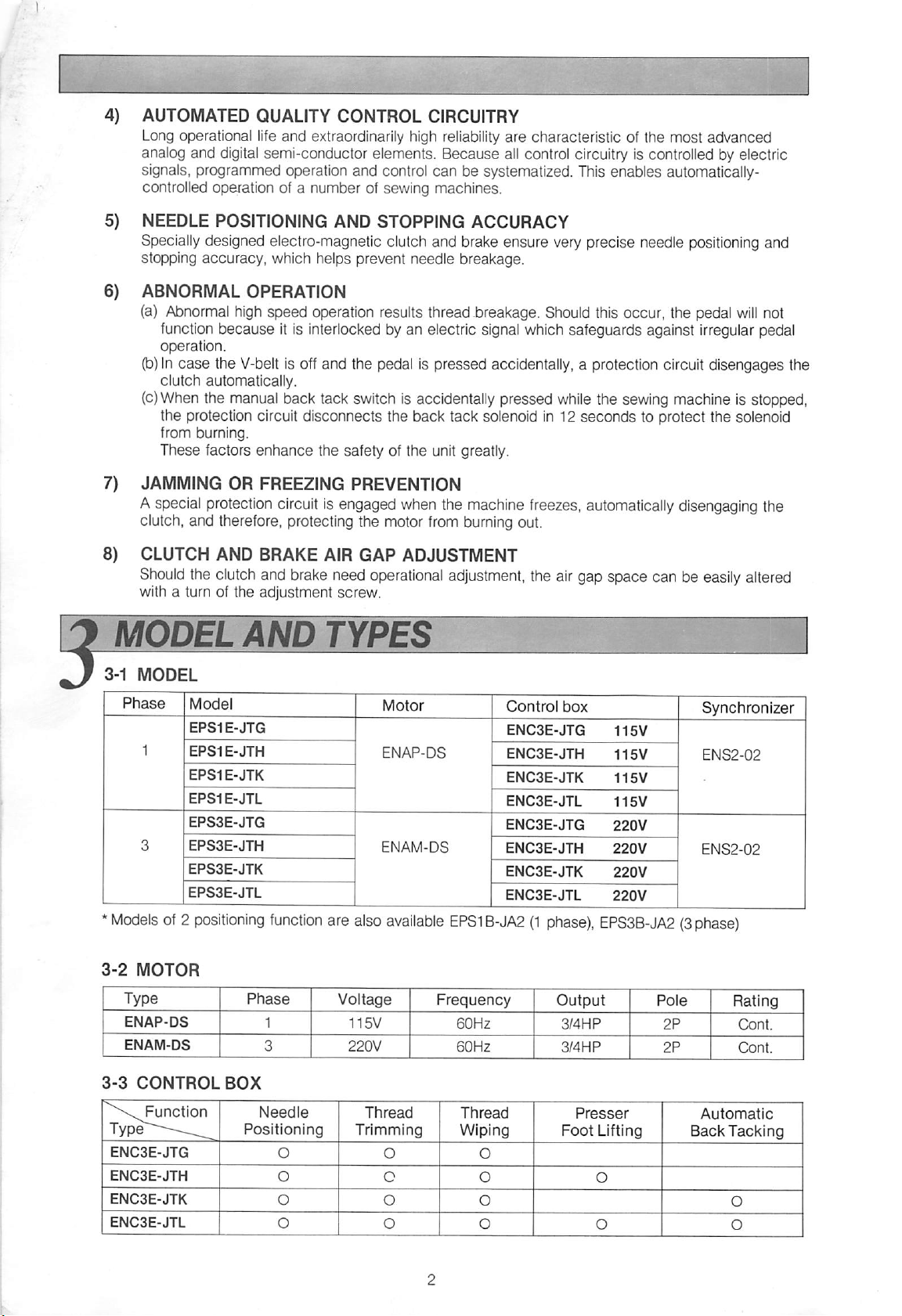
Phase
*
Modelsof2
3-2
MOTOR
ENAP-DS
ENAM-DS
3-3
CONTROL
Function
ENC3E-JTG
ENC3E-JTH
ENC3E-JTK
ENC3E-JTL
Model
EPS1E-JTG
EPS1E-JTH
EPS1E-JTK
EPS1E-JTL
EPS3E-JTG
EPS3E-JTH
EPS3E-JTK
EPS3E.JTL
positioning
Phase
BOX
Positioning
function
Needle
are
also
Voltage
115V
Trimming
Motor
ENAP-DS
ENAM-DS
available
Thread
O
Control
ENC3E-JTG
ENC3E-JTH
ENC3E-JTK
ENC3E-JTL
ENC3E-JTG
ENC3E-JTH
ENC3E-JTK
ENC3E-JTL
EPS1B-JA2(1phase),
Frequency
60Hz
60Hz
Thread
Wiping
O
Output
box
EPS3B-JA2(3phase)
3/4HP
3/4HP
Presser
Foot
Lifting
Pole
2P
2P
Synchronizer
ENS2-02
ENS2-02
Rating
Cont.
Cont.
Automatic
Back
Tacking
Page 5
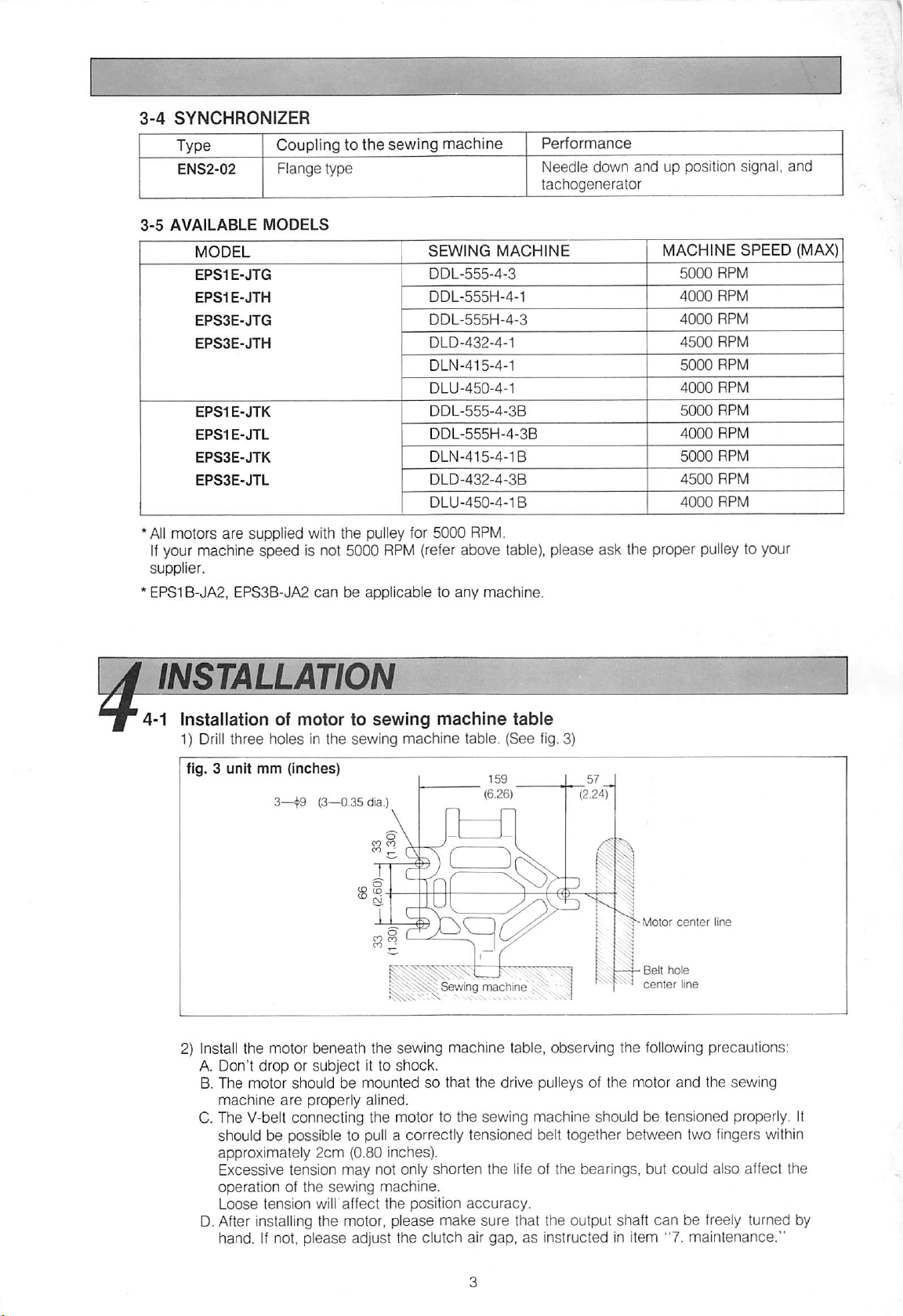
3-4
SYNCHRONIZER
Type Coupling to
ENS2-02 Flange type
3-5
AVAILABLE
MODEL
EPS1E-JTG
EPS1E-JTH
EPS3E-JTG
EPS3E-JTH
EPS1E-JTK
EPS1E-JTL
EPS3E-JTK
EPS3E-JTL
All
motors
If
your machine speed is not 5000
supplier.
EPS1B-JA2,
MODELS
are
supplied with the pulley for
EPS3B-JA2
canbeapplicabletoany
the
sewing machine
SEWING
DDL-555-4-3
DDL-555H-4-1
DDL-555H-4-3
DLD-432-4-1
DLN-415-4-1
DLU-45D-4-1
DDL-555-4-3B
DDL-555H-4-3B
DLN-415-4-1B
DLD-432-4-3B
DLU-450-4-1B
5000
RPM
{refer
Performance
Needle down
and
up position signal,
tachogenerator
MACHINE
MACHINE
5000
4000
4000
4500
5000
4000
5000
4000
5000
4500
4000
SPEED
RPM
RPM
RPM
RPM
RPM
RPM
RPM
RPM
RPM
RPM
RPM
RPM.
above table), please ask the proper pulleyto your
machine.
and
(MAX)
INSTALLATIQ
4-1 Installation of
1)
Drill
three holes in the sewing machine table. (See fig. 3)
ftg. 3
unit
2) Install the motor beneath the sewing machine table, observing the
A. Don't
B. The motor should be
machine
C. The V-belt connecting the motor to the sewing machine should be tensioned properly. It
should
approximately
Excessive tension may not only shorten the life of the bearings, but could also affect the
operation of the
Loose tension will'affect the position
D.After installing the motor,
hand. If not,
motortosewing
mm
(Inches)
3—^9 (3—0.35dia.)
droporsubject
are
properly alined.
be
possible to pull a correctly tensioned belt together between two fingers within
2cm
It to
mountedsothat
(0.80 Inches).
sewing
machine.
shock.
machine
machine
the
table
drive pulleys of the motor
accuracy.
please
please
adjust the clutch air gap,asinstructed in item "7, maintenance,"
make
sure
that the output shaft
Moior
center
line
Beit
hole
center
line
following
can
precautions:
and
the sewing
be freely turned by
Page 6
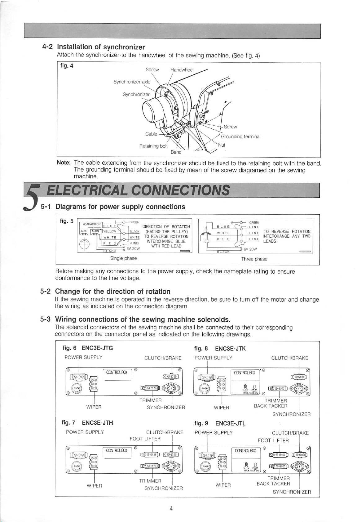
4-2
Installation of
Attach
synchronizer
the synchronizer-to the
handwheel
of the
sewing
machine.
(See
fig.
4)
ftg. 4
Synchronizer axle
Screw
Handwheel
Synchroniz^^r^^^^^N
Retaining bolt
Band
Note: The cable extending from the synchronizer should be
5-1
The grounding terminal should be
machine.
TTMCAICONNECTIO
Diagrams
fig. 511.^.oAriT^
y
for
I
torn.
,,
MAIN
power
'IB
LUE(
"IyELLOW
1^
WHITE
I n E
iLACK
'ii—<t>—
Di
Single
supply
QR^
GREEN
Bu>CK
WHITE
^
20W
^
phase
connections
DIRECTION OF ROTATION
(FACING
TO REVERSE
fixed
THE
INTERCHANGE
RED
PULLEY)
ROTATION
BLUE
LEAD
Grounding terminal
•Nut
fixed
to the retaining bolt
with
the band.
by mean of the screw diagramed on the sewing
I I
GREEN
LINE
LIMETOREVERSE
INTERCHANGE
^
LEADS
LE
t 6V
20W
Three
phase
ROTATION
ANY TWO
Before making any connections to
conformancetothe
5-2
Change
for
the
line voltage.
direction
If the sewing machine is
operated
the
of rotation
in the reverse direction,besure
the wiringasindicated on the connection diagram.
5-3
Wiring
The solenoid
connectors
connections
connectors
of
the
sewing
of the sewing machine shall be
on the connector panelasindicated on the following drawings.
fig. 6 ENC3E-JTG
POWER
fig. 7 ENC3E-JTH
POWER
1
SUPPLY
1
WIPER
SUPPLY
TRIMMER
FOOT
CLUTCH/BRAKE
SYNCHRONIZER
CLUTCH/BRAKE
LIFTER
power supply,
machine
1 1
1
check
the nameplate rating to
to turn off the motor
solenoids.
connected
fig. 8 ENC3E-JTK
POWER
SUPPLY
WIPER
fig. 9 ENC3E-JTL
POWER
SUPPLY
to their corresponding
1
TRIMMER
BACK
FOOT
ensure
and
CLUTCH/BRAKE
TACKER
SYNCHRONIZER
CLUTCH/BRAKE
LIFTER
change
1
Page 7

5-4
Synchronizer
Before starting operation, Insert the synchronizer connector into the corresponding
connector
5-5
Connection
Two black wires
Please
5-6
Changing
The transformer which is located in the control box
At ex-factory, it is
Before starting operation,
proper
connect
terminal.
panel.
the
connection
of
the
lighting
are
provided for 6 Volt 20 Watt lighting fixture in the
properly
when
primary
used
the 220v tap.
check
fixture
it willbeneeded.
taps
of
the
transformer
your power supply and if
has
connector
end
coverofthe
used
in 220V
the four taps (190v-208v-220v-240v).
necessary,
control
change
the connection to
motor.
box
on the
the
OPERATION
When the foot pedal of the sewing machine is pressed forward, the pitman rod moves the speed governor
in the control box. The clutch coil is energized by a control system so that the sewing machine can be
operated
When the sewing operation is completed and the foot pedal is released to Its neutral position, the brake
coil is energized through the control circuit. By means of the synchronizer, the sewing machine
in the needle down position immediately. By heeling the foot pedal backward, the clutch coil is
reenergized. Therefore, the sewing machine
speed and the thread
needle up position, the thread wiping operation is performed once.
at the desired
speed;
trimming
depending on the position of the foot pedal.
will
move into the needle up position at the thread
operation
will
be performed.
After
the sewing machine is stopped in the
will
stop
trimming
fig.
10
Fool pedal
Pressed
forward
Pressed
backward
Note:
(a) The handwheel of the sewing machine can be turned
not operating.
(b.)
When the operator stops the sewing machine in the needle down position, once
freely
when the sewingmachine is
she
the handwheel of the sewing machine manually, the thread trimming and thread wiping
operations
BACK
JTK and JTL type motors have an automatic back tack operation. The automatic start
is performed at the beginning of the sewing operation by pressirig the pedal forward. The end back
tacking is performed at the completion of the sewing operation by heeling the pedal backward.
Even when the pedal is released to Its neutral position at the end back tack, the sewing machine is
moved
tacking. The sewing
When the pedal is released to its neutral position at the start back tack, the sewing machine
immediately stop in the needle down position. By heeling the pedal backward during the start back
tack,
tacking.
TACKING
into
the
the
sewing
cannot
needle
machine
be performed even when the foot pedal is heeled backward.
up position: performing
machine
then
performs
performs
the
thread
the
the
thread
trimming
thread
trimming operation after the
wiping operation.
and
wiping operation without the
back
end
turns
tacking
back
end
will
back
Page 8

1) Back
The
Start
back
End
back
fig. 11
tack
patterns
tacking
tacking
patterns
are
selectedbychanging
START
upper
OFF
down
A—,B
B-r---A
A
OFF
.bVbs
START
BACK
TACK
BACK
position
position
position
END
SW.
TACK
the
BACKTACK SW.
SW.
upper
position
OFF
position
down
position
locatedonthe
Pattern
connector
panel.
Programming
2)
The switch to program the stitches of
control
the
box. {fig. 12)
stitchesofback
tacking
back
Back tacking is consisted of two portions, Part A
PART A; forward portion of
PART B:
backward
portion of
The stitches of part A and B
switch.
Note:
Part
A Is
double
The
programming should be
back
back
can
only.
donebychanging
tacking
tacking
be programmed independently from 0 to 15 by changing
tacking is located on the "L P. C. Board" in the
Conirol
box
L P.C.Board
Switchestoprogram
the
stitchesofback
Screwstofix
and
'
the
cover
Part B.
the switchasper
tacking
(fig.
o
i=^t=]i=iao
O 0
13)
the
following combination table.
the
table
6.2
Switches
AI B 0
1 1 OFF
2 2 OFF
4 4 OFF
8 ^
Combination
table
1
ON
OFF
OFF
OFF
OFF OFF
Ml
Number
2
5
m
6
Bl
OFF
ON ON
ON
OFF
SWITCH
of
ON
ON
OFF
stitches
B
OFF
OFF
ON
9
ON
OFF
OFF
ON
10
10
OFF
ON
OFF
ON
11
12 13 14
OFF
ON
OFF
Page 9

Example:
When
the
start
back
tacking is programmed to 3 stitches forward and 4 backward, the
tacking is
4
stitches
forward
and3backward.
fig. 15
6-2
FOOT
JTH
backwardtothe
and
LIFTING
JTL type
Switches
B
4
8_
1
A 2
motors
intermediate position while the
haveapresser
foot lifter.
T
The
needle
presser
is down position.
Position
OFF
OFF
ON
OFF
ON
ON
OFF
OFF
foot is lifted by heeling pedal
When
the
pedal is fully
heeled backward, the needle is positioned at the upper position while thread trimming and wiping
are
operations
pedalisheeled
performed before
backward.
lifting
the
presser
foot. The
presser
foot is kept liftedaslongasthe
end
back
6-3
fig.
16
SLOW
1)
START
AND
Numberofneedle
NUMBER
positions
OF
NEEDLE
POSITIONS
When the single positioning is. required, open the control box
located on the "L P. C. Board" from
2)
Slow
start
When the slow start is required at
the
select
switch
combination
table
"3"
and
"4"
table,
(table 6.3)
-
imczzicncn
o o
6.3
Switch
Number
3
^
"OFF"to"ON"
the
beginning of the sewing, open the control box and
located on the "L P.0.Board" in
— L
P.O.Board
^
Select
switch
Number
oil
OFF
OFF
OFF
Intermediate
Full
and
position,
m-
•]"
zo
of
stiches
change
(fig.
accordance
—»
—
"1
—^
-T
at
I 2 I
ON
the select switch
19)
Numberofneedle
Slow
start
slow
start
with the following
~3~
ON
ON I OFF ON
"1"
change
position
Page 10

REPAIRS
1)
Adjustment
A) Turn the
AND
counterclockwise
untilItbecomes not to turn the output
ADJUSTMENT
of
clutch
adjustment
at
air
screw
least
two
gap
turns,
ft—
Clutch
Clutch
end
end
cover
cover
B) Turn
the
adjustment
carefully until
tighter.
zero
(At
and
this
the
screw
the
rotation
point,
output
shaftisturned
clockwise
becomes
clutch
air
gap
is
J
li—
iLJi
1l^Tll\
\|
Complete
the
(8
stepsofnotches).
C)
When
brake
2)
Replacement
A)Switch off the motor, remove the pitman rod from the
B) Pull out all
C) Remove the control box from the motor and replace it with the new control box.
3)
Replacement
A)
Pull
board.
B) Remove the strain relief.
C) Unscrew
from
D)
Replace
the
adjustmentbyturning
adjustment
the
air
out the connector connected from the
the
screw
clutch air
gapisdone
of
the
connectors
of
speed
five
screws
control
it with
box,
the
120®
clockwise
gapisadjusted,
accordingly.
control
which
new
and
speed
box
unscrew
control
(JTK,
JTL type)
fix
the speed control lever assembly to the control box, and remove it
control lever
the four bolts which hold the control box to the motor.
lever
W
1
assembly
speed
control lever assembly to another printed circuit
assembly.
speed
control lever.
Ihuuu^^
HI
llvQ^
Adjustment
screw
JTG,
JTK, JTL
Important:
Removal
to avoid
4)
Replacement
A) Pull
B)
C)
D) Reinsert
JTH
type
type
and
replacement of circuit
static
electricity
of
out
all
connectors
connectedtothe
Remove
printed circuit
Replace
board
the
it with a
"M."
securely
four
board
damageto"MOS"
printed
printed circuit
screws
new
all
circuit
which
which fix
"M."
printed circuit
connectors.
are
! I
board
boards
board
the
must be done by qualified service personnel with
component.
"M"
FT
(JTK, JTL
77
screws
type)
u
care
Page 11

Replacement
A) Puli out all
B) Push the nail to free the lock of the nylon
of printed circuit
connectors
which
are
connected
board
"L"
(JTK, JTL
to the printed circuit board "L."
spacer,
and
C) Relace itwith a new printed circuit board "L" and push
D)Reinsert
securely
all
connectors.
type)
remove the P, C. Board
until
the board is snapped completely.
"L"
fig. 21
6)
Replacementofprinted
Nylon
Cover
Push
spacer
heretofree
—
circuit
the
lock
board
"C"
(JTG, JTH type)
Refer to the Instruction of replacement for the printed circuit board "M."
7)
Replacement
A)
Remove
B)
Unscrew
machine.
C)
Then
replace
Coution:
With cover removed
cause
severe
plates
with
Note: If
necessary,
sewing
rotation is
magnet carrier plate; which
of
the
the
connector
the
three
it with a
and
synchronizer
from the control box.
screws,
and
new
adjusted
power on, the rotation of
remove
synchronizer.
(See
fig. 22)
the
synchronizer from the
the
synchronizer
physical injury to hands, arms, etc. Never remove cover or adjust magnet carrier
power
on.
readjust the needle stop position by turning the
machine
manually into
correct!)
Remove
the
has
the
needle
cover
the red
down position. (Make
from
the
synchronizer, loosen
magnet
so that it
on the synchronizer socket. Then turn the sewing machine to the needle up position and
"2"
make
magnet
position on
a fine
adjust the
in
the
To
A) Pullout the solenoid
B)
Operate
C)
Press
the
D) Make
sure
carrier plate; which has the yellow
the
synchronizer
adjustment;
connectors
the
sewing
foot pedal forward
the
sewing
machine.
machine
of the sewing machine from the control box.
and
release.
is in
socket.
the
needle
down position.
E) Correct to the required needle position by adjusting the red
F) Heel the foot pedal backward. (Needle stops in the up position.)
G)Correct to the required position by adjusting the yellow
H)Tighten
I) Finally reinsert the solenoid connectors of the sewing machine to the control box.
the
screw
and
install
the
synchronizer
cover.
P. C.
will
magnet
magnet
Board
"L"
handwheel
magnet
magnet
carrier plate
carrier plates. Turn the
sure
that
the
be located in the
so that the plate
magnet
carrier plate.
carrier plate.
of the
the
direction of
screw,
sewing
can
and
"1"
will
be located
turn
position
the
fig. 22
Magnet carrier plate (red)
Magnet carrier plate
Synctironlzer
(yellow)
socket
Page 12

Use of
special
lining application material
For longer lining life, it is important that the lining shouldbecoated
use
the
materialifnoiseisheardinthe
Note: Don't
use
any
application material
clutch
other
and
brake.
than this for
the
PANA-STOP E. This
enough for 4 applications, and the material should be used accordingly.
at least
once
a half year. Also
tube
contains
How to
A)
use;
Motor
disassembly
a) Switch off the motor,
b) Pull
c)
out
Remove
the
the clutch
(fig. 23)
three-pole
end
and
connector
d) Remove the spline cover
remove the pulley cover and V-belt.
from
the
control box.
coverbyunscrewing
and
the spring.
the
three
bolts.
e) Remove the clutch disc from the output shaft, and remove the nylon ring together with the
brake
disc.
Note: Be careful not to drop otherwise
lining
surfaces.
fig. 23
Motor
Don't permit
disassembled.
bracket
dusttoadheretothe
Flywheel
Bearing
damage
lining
housing
the movable plates, nor to
surfacesofthe
Nylon ring
(Clutch)
Moving
moving
disc
-&J
scratchorscar
discs
while they
Clutch
end
\-
Bolt
cover
Three-pole
connector
the
are
8)
Cleaningofmoving
Clean
away
any
flywheel
any
C)
Applicationtolining
a)
and
each
cotton
waste
Squeezeanamount
surfacesofeither
Note: Be careful not to apply
precision, or
b) Firmly
press
c) Rotate the moving
discs
cotton
wasteorother
ventilation
adheredtothe
surfaces
equal to
the
clutchorbrake
the
the
uncoated
discs
and
motor
channelofthe
lining
about2match
too
motor might not
lining
surface
against
each
d) Clean away any excessive material which
fig.
24
KooJ
fig. 26
interior
dirt
adheredtothe
motor
surfaces.
heads
in 8
places.
much,
because
operate
against
other. (See fig. 26)
comes
moving
bracket.
from
(See
fig. 24)
this
may
evenifpower
the
coated
Use
the
tube
cause
surface.
discs,
clutch
end
a soft, dry
and
apply to
clothtoclean
the
a malfunction of stopping
Is turned on.
(See
fig. 25)
cover,
away
lining
out between the lining surfaces. (See fig. 27)
fig. 25
fig. 27
Page 13

9)
D)
Applicationtoclutch
Clean
away
any
of the clutch shaft, and apply the material evenly.
E)
Motor
assembly
Assemble
F)
Break-in
Perform a break-in operation soon after application of material to the lining surfaces.
a) Switch on
b)
After
more
Note: Iftoo much material Is applied to the lining surfaces, the motor might not
the
motor In the
operation
the
the motor is operating
than
100
cotton
motor.
times.
shaft
waste
adhered
opposite
normally,
to the
cogs
orderofdisassembly.
perform the break-In operation by operating the pedal
power is turned on.Ifthis happens, remove excessive material from the
Cleaning
When
shorten
Cleaning
A)
Remove
up
the
filter
the
filter is filled up with the
the
service
up:
the
life of
filterbypulling
the
cotton
motor
and
the
partAshown
waste,
reduce
the motor will be
efficiency.
in
29
heated
up. This
(a)
operate
friction
may
even if
disc surfaces.
0)
Replace
10)
Adjustment
The pull strength of the
the spring. When the
the
filter.
of
the
Clutch
end
ccwer;
speed
speed
pull
control
control lever
strength is adjusted too lighter, positioning accuracy
lever
strength
willbechanged
by relocating the hooked position of
m\7(
will
/
be Impaired.
Page 14

Adjustment of
The potentiometers to adjust the
a) f^aximum
The maximum
the
maximum
speed
(JIG, JTH, JTK and JTL)
speed
is adjustable by the potentiometer
speed
speeds
and back tacking
are
located on the front of the control box.
"MAX."
lower than 2000RPM. At ex-factory, it is adjusted the highest position.
speed
The lower
speed
will
b) Back tacking
The start back tacking speed is
upper
limit
back tacking is
The upper
back
tacking should be adjusted by the potentiometer "B.T." from 1000RPM to 2500RPM.
fig. 31
is convenient for the training the beginner. However, the longer
shorten
which is adjusted
limit
the
life of
the
clutch
and
brake
linings.
speed
(JTK
and JTL)
2000RPM
linearly
2000RPM
and the speed of forward portion of the end back tacking is
variable by pressing the pedal
at ex-factory.The speed of backward portion of the end
of the start back tacking speed and the speed of backward portion of the end
speed
from the synchronous
use
forward
from
speed
of the lower
180RPM
1500RPM.
to
to
HOW
In
case
the trouble,
1) Switch off
2) Pull out all
TROUBLESHOOTING
PROBLEM
Motor
does
start
when
main
switch
Motor
runs,
when
activating
sewing
pedal,
the
machine
start.
TO
the
connectors,
not
turning
on.
but
machine
does
motor.
not
CAUTION
JTG,
JTH.
CHECK
proceedasfollows:
then
reinsert
PROBABLE
Power supply
switch)
Power supply
protection
Motor winding
Plug for
clutch
in plug for
interrupted-
Plug for
brake not inserted.
Power
for
plug not inserted.
Fuse
Clutch air
narrow, or
use,
defective.
Control
not properly
synchronizer,
cord
synchronizerorclutch
supply
control
in control box
gap
clutch
box
THE
them.
CAUSE
cord
cord
switch)
defective.
defective:
clutch
cord
box
defective,
too
after
a long
lining
defective.
DRIVE
(plug, protection
connected.
(plug, cord,
defective.
clutch,
connection
and
brake
(plug,
cord)
or
open.
time
of
worn
down
or
CAUTION
JTK.
JTL.
UNITt
CORRECTIVE
Correct
with
Instructions.
Replace
Replace
repaired by
or
and
Replace
repair
connections
Plug in.
Replace
or plug in.
Replace
Adjust
clutch
ordance
If
necessary
brake
discs.
Replace
ACTION
connection
defective parts.
motor or
manufacturer.
defective
defective parts,
fuse.
with
control box.
in
have
parts
respectively.
air
gapinacc
Instructions.
replace
accordance
motor
or
clutch
and
Page 15

Motor
decreases
speed
considerably
stops
entirely.
Motor
Motor
Once
turned
machine
without
being
overheats.
overheats.
main
on
operates
pedal
actuated.
Stopisonly
possible
by
switching
switch
off.
or
PROBABLE
CAUSE
Voltage too low.
Machine or
trimmer) binding or
devices
seized.
Power rating of motor
for particular operation.
Control
Air
clutch
Machine or
trimmer) binding or
Clutch air
Clutch
box
channels
filled
and/or
defective.
within
with
devices
gap
brake
motor
lint.
(e.g.
seized.
too narrow.
coil
defective.
Motor
winding
Control
Two
phase
phase
motor.
Machine
actuates
Clutch air
Control
box
box
defective.
defective.
operation for three
pedalisjammed
by own weight.
gap
too narrow.
defective.
(e.g.
too
thread
low
and
thread
or
CORRECTIVE
ACTION
Have power supply checked,
Repair
Exchange
higher
Replace
Clean
machineordevices.
motor
for
another
power
rating.
control
air
channels
box.
in
motor
clutch.
Repair
Adjust clutch air
accordance
Replace
Replace
Replace
Check the power supply.
Replace
Adjust clutch air
accordance
Replace
machine
or devices.
gap
with
Instructions.
defective parts.
motor.
control
or repair pedal.
control box.
with
box.
gap
Instructions.
in
in
with
and
Machine
first
actuation
full
speed.
only
possible
switching
Irregular
or
stopping
continuation
operation
stop
signal
Stop
only
by
switching
Intermediate
speed
ranges
missing.
runs
only
positioning
maximum
runs
at
at
Stop
by
off.
of
after
given.
possible
off.
are
(Machine
at
or
speed.)
Cord of
connection
plug
Synchronizer
Control
synchronizer
in synchronizer or
broken.
defective.
box
defective.
torn off,
Hub of synchronizer in-
securely
TensionofV-belt
enough.
Machine pedal is
actuatesbyown
Positioning
machine
synchronizerismounted)
too
Synchronizer
Control
Synchronizer
Control
high.
fixed on
V-belt
speed
shaft
box
defective.
box
defective.
machine
not
taut
slips.
jammed
weight.
(speed
on
which
defective.
defective.
or
of
shaft.
Repair
Replace
Replace
Fix
Instructions.
Correct
with
Repair or
Adjust
speedinaccordance
Instructions.
Replace
Replace
Replace
Replace
cordorconnections.
synchronizer.
control box.
hubinaccordance
tensioninaccordance
Instructions.
replace
correct
positioning
synchronizer.
control box.
synchronizer.
control box.
with
pedal.
with
Page 16

PROBLEM
Motor
noise
and
vibration.
has
unusual
PROBABLE
Clutch
Clutch
Clutch
friction
defective.
Hub of
fixed
Control
TensionofV-beit
nottaut
CAUSE
air gap too
bearing defective.
and/or
brake
disc
worn
synchronizer
on machine shaft.
box defective.
enough.
Pulleys of motor
are not alined.
Additional
connected,
No
additional
functions
trimming,
foot
lifting,
{e.g.
wiping,
etc.)
defective.
Additional
(e.g.
valve is
knife
Control
\A/hen
ordering extra control box, printed circuit board, or
repair,
please
refer to
the
following tables.
device
device
magnet
jammed
jams,
box
cord
or magnetic
etc.)
defective.
wide.
lining, or
down
or
insecurely
too
taut
or
and
machine
improperly
wrong
or
defective
or burn out,
speed
CORRECTIVE
ACTION
Adjust clutch air gap.
Replace
Replace
Fix
instructions.
Replace
Correct
with
Alined.
Correct
replace
bearing.
defective parts.
hubinaccordance
control box.
tensioninaccordance
instructions.
connections,ifnecessary,
cord.
Repair devices.
Replace control box.
adjuster
assembly
with
for service or
1)
Control
I
box
TYPE
2) Printed circuit
PHASE
1
3
1
3
1
3
1
3
boards&Speed
"M"
P.O.
Board
MTS-N5801101 MTS-N5801501
MTS-N5801201
adjuster
MTS-N5801501
( I
P.O.
assembly
Board
"C"
P.O.
Board
fvlTS-N5801401
PARTS
NUMBER
MTS-N5905501
IV1TS-N5905101
MTS-N5905601
MTS-N5905201
MTS-N5905701
MTS-N5905301
MTS-N5905801
MTS-N5905401
Speed
MTS-N5905901
adjuster
ass'y
Page 17

Page 18

Note
Part
No.
MTS-N2007601~
MTS-N7001213
MTS-N7000112
SL-4Q5tQ41-SE
MTS-N2007701
NM-6100002-SE
MTS-N2500501
SL-4040841-SE
M'^-N2007a01
MTS-N1300301
MTS-N7001006
MTS-N7000606
MTS-N20Q7901
MTS-N70006Q7
MTS-N7t0011t
MTS-N2501401
MTS-N1300401
MTS-N7100316
MTS-N2501501
MTS-N2700501
SL-4041091-SE
MTS-N2006001
WT-0400QQ1-KE
MTS-N7000109
MTS-N5101601
MTS-N5101501
MTS-N7000113
M7S-N5906501
MT5-N2500601
MTS-N7100112
MTS-N10Q2301
MTS-N2QQ80Q1
VVT-04Q(X>04-KE
SM-1040e01-SE
MTS-N7000114
MTS-N20081QT~
MTS-N1002401
MTS-N
2003201
MTS-N1002501
MTS-N7001001
MTS-N7001003
MTS-N7001222
MTS-N2009501
MTS-N7000608
•20
MTS-N5200601
•10
MTS-N52007Q1
MTS-N2Q0B301
MTS-N7000115
•20
MTS-N5101701
•10
MTS-N5101B01
•20
MTS-N5102201
•10
MTS-N5102301
NU-6100002-SE
WS-1020002-KR
WP-1052001-SE
MTS-N7000207
MTS-N20096Q1
MTS-N2008401
MTS-N2009701
MTS-N20085Q1
MTS-N1002601
MTS-N70002Q5
MTS-N7001216
WS-Oe20002-KR
NM-6060002-SE
•20
MTS-N7109941
•10
MTS-N7109942
MTS-N7000116
MTS-N2008601
MTS-N7000117
•20
MTS-N2008701
•10
MTS-N
2008801
MTS-N20C8901
MTS-N
7000122
SM-8051030-SE
MTS-N7001223
♦10
MTS-N7109943
•10
MTS-N2009001
•10
MTS-N7000116
"74
MTS-N1300501
For single
10
...
... For 3
... For JTG
... For JTK
phase
type
type
20
...
70
...
71 ...... For JTH type
72
...
phase
motor
Description
Pulley
coverB
Washer
Screw
Screw
Pulley
cover
NutMIO
Tutje
Screw
Cover
Adjusimeni
Ball
bearing
Key
Output
shall
Key
Spring
Filter
ass'y
Ciulch-end
Connectorass'y
Strain
relief
Bushing
Screw
Friction
disc
Toothed
ioci<
Screw
Brake
coil
ass'y
Clutch
coilass'y
Screw
Moving
disc
Nylon
ring
Spring
Bearinghousing
Washer
Toothed
lock
Screw
Screw
Collar
Flywheel
Fan
Motor-end
cover
Ball
bearing
Ball
bearing
Thrust
wave
Retainingring
Key
Rotor
ass'y
Rotorass'y
Collar
Screw
Frame
ass'y
Frameass'y
Frame
ass'y
Frame
ass'y
NuiMiO
Spring
washer
Washer
Belt
adjusting
Retaining
ring
Belt tightener hinge pin
Belt
tightener
Washer
Belt
tightener
Mounting
bolt
Washer
Spring
washer
Nut
MS
Terminal
block
Terminal
block
Screw
Terminalwasher
Terminal
screw
End-cover
End-cover
Strain
relief
Grounding
screw
Set screw
Washer
Capacitor
Mounting
plate
Screw
Control
box
motor
•73
•74
•75
•76
A
screw
6302
cover
washer
ass'y
washer
6202
6203
washer
M10
bolt
hinge
pin
M8
... .. For JTL type
... .. For JTG, JTH type
.. For JTK. JTL type
..
... For JTH. JTL type
...
Big
Big
Big
Big
BiH
Biia
BiEl
gpi
Bn
MTS-N
1300602
MTS-N59Q5901
MTS-N5906001
MTS-N59Q6101
MTS-N59C6201
MTS-N7000119
MTS-N20091D1
MTS-N2009201
MTS-N2009301
MTS-N2009401
MTS-N7109944
MTS-N7109945
MTS-N7000120
MTS-N2700601
MTS-N71C9946
NM-6040002-SE
WS-04t0002-KR
WP-0430801-SE
SM-4041001-SE
MTS-N7109947
MTS-N7000121
MTS-N5705601
MTS-N5705701
WP-0531001-SE
MTS-N7109926
MTS-N570580t
MTS-N5705901
MTS-N5706001
MTS-N5706101
MTS-N5706201
MTS-N5706301
MTS-N5706401
MTS-N5706501
MTS-N5801101
MTS-N5801201
MTS-N7001221
MTS-N7001220
MTS-N58C1501
MTS-N7109948
MTS-N7109927
MTS-N2501601
MTS-N2501701
SM-4041Q01-SE
ST-4040321-SH
MTS-N5801301
MTS-N5801401
MTS-N7109949
MTS-N2501801
MTS-N7109950
MTS-N5906601
MTS-N7000111
MTS-N2500601
MTS-N2500901
MTS-N5901101
MTS-N5901201
MTS-N2501001
SM-1C51601-SE
MTS-N2S01101
MTS-N7000304
MTS-N7000407
MTS-N2501901
MTS-N5101901
MTS-N5102001
MTS-N6102101
MTS-N5901301
MTS-N7109935
MTS-N7109951
MTS-NS905501
MTS-N5905601
MTS-N5905701
MTS-N5905801
MTS-N5905101
MTS-N5905201
MTS-N5905301
MTS-N59054Q1
MTS-N57022Q1
MTS-N570660t
MTS-N5706701
Control
Speed conirollever ass'y
Speed controlleverass'y
Speed conirol lever
Speed controlleverass'y
Screw
Washer
Mounting plate A
Mounting
Mounting
Potentiometer
Potentiometer
Screw
Cap
Reslster
Nut
^rlng
Washer
Screw
Rectllier
Screw
Transformer
Transformer(Ph.
Washer
Capacitor
Connector
Connector
Connector
Connector
Connector
Connector
Connector
Connector panel
Printed
Printed
Nylon
Nylon
Printed
(Dover
Mounting
Strain
Strainrelief
Screw
Tapping
Printed
Printed
(Dover
Nylon
Fuseholder
Tachogenerator ass'y
Mounting
Spacer
Spacer
Magnetcarrier plate
Magnet carrier plate
Magnet
Screw
Cover
Retainingboll
NutSM
Nylon
Clutch-endcover ass'y
Rotorand
Rotorand
Synchronizer
Fuse
Special
CDontiol
(Dontrol box
(Dontrol box
(Doniioi
(Dontrol
(Dontrol
Conirolboxass'y
(Dontrol
Springass'y
Springass'y
Spring
. with trimmer an(J wiper
. with trimmer, wiper
. with
trimmer,
with
trimmer,
presser
foot
wiper
wiper,
lifter
and
and
back
Pox
plate B
plate
with
washer
(Ph.
220V)
115V)
panel
ass'y
panel
ass'y
panel
ass'y
panel
ass'y
panel
ass'y
panel
ass
panel
ass'y
ass'y
circuit
boardMass'y
circuit
tioardMass'y
washer
washer
circuit
boardLass'y
ass'y
spacer
relief
screw
circuit
board
circuit
board
ass'y
bushing
screw
for
magnet
carrier
plate
15(64
band
flywheel
flywheei
lining
application
box
ass'y
ass'y
ass'y
boxass'y (ti5V)
boxass y
boxass'y
box
ass'y
ass'y
presser
back
tacker
tacker
ass'y
switches
(HSV)
(115V)
(115V)
(115V)
(220V)
'y (220V)
(220V)
(220V)
cass'y
cass'y
carrier
holder
ass'y
ass'y
material
(ttSV)
(itSV)
(itSV)
(22QV)
(220V)
(220V)
|22QV)
foot lifter
and
plate
Page 19

EXPLODED
116
/
372 350
VIEW
119
1
Life
120
116 ®
n (S» •
-"»
 Loading...