

Page 1

MS-1261A-DWS
INSTRUCTION MANUAL
Page 2

CONTENTS
1. SPECIFICATIONS ............................................................................................................ 1
1-1. Specications of the sewing machine head ..................................................................... 1
1-2. Specications of the control box ....................................................................................... 1
2. SETUP ..............................................................................................................................2
2-1. Setting up the sewing machine .......................................................................................... 2
2-1-1. Adjusting the sewing machine head ........................................................................................ 2
2-1-2. Changing the position of the operation panel ........................................................................3
2-2. Installing the thread stand .................................................................................................. 3
2-3. Oiling and draining of oil .................................................................................................... 4
3. PREPARATION BEFORE SEWING ................................................................................ 5
3-1. Attaching the needle ........................................................................................................... 5
3-2. Threading the machine head .............................................................................................. 6
3-3. Adjusting the thread tension .............................................................................................. 7
3-4. Adjusting the stitch length ................................................................................................. 8
3-5. Adjusting the needle guard ................................................................................................ 9
3-6. Adjusting the looper thread cam ...................................................................................... 10
3-7. Adjusting the feed dog height .......................................................................................... 10
3-8. Adjusting the take-up thread tension control lever ........................................................ 11
3-9. Adjusting the position of the intermediate tension release lever and needle thread
tension controller .............................................................................................................. 11
3-10. How to adjust the cloth puller .......................................................................................... 12
3-10-1. Adjusting the cloth puller belt and its longitudinal position .............................................12
3-10-2. Adjusting the inclination of the cloth puller belt.................................................................13
3-11. LED hand light ...................................................................................................................13
3-12. To use the sewing machine with a cloth puller for sewing heavy-to medium-weight
materials ............................................................................................................................. 14
3-12-1. Replacing the feed dog .........................................................................................................14
3-12-2. Changing the throat plate .....................................................................................................14
3-12-3. Adjusting the difference in height of the presser foot ......................................................15
3-12-4. Replacing the needle thread guide ......................................................................................15
3-13. Table of replaceable gauges ............................................................................................. 16
3-14. Adjusting the material edge detector .............................................................................. 17
3-15. Needle cooler ..................................................................................................................... 18
3-15-1. Adjusting the position of the blow pipe ............................................................................... 18
3-15-2. Adjusting the air ow.............................................................................................................18
3-16. Chain-off thread cutter (suction of thread waste) .......................................................... 18
4. HOW TO USE THE OPERATION PANEL .....................................................................19
4-1. Explanation of the operation panel switch ..................................................................... 19
4-2. Operation to be done at rst ............................................................................................ 20
4-2-1. Selection of the language .......................................................................................................20
4-3. How to select a sewing pattern ........................................................................................ 23
4-4. How to change the sewing data ....................................................................................... 24
4-4-1. Method of changing the sewing data ..................................................................................... 24
4-4-2. Method of selecting a specic sewing data item .................................................................. 24
4-4-3. How to change the part number, process or comment for the sewing pattern data .........26
i
Page 3

4-4-4. How to carry out teaching of the multi-layered section of material .................................... 27
4-4-5. Sewing data on a free sewing pattern ...................................................................................28
4-4-6. How to edit a step sewing pattern .......................................................................................... 34
4-4-7. How to carry out the teaching of the number of stitches ....................................................38
4-4-8. List of sewing data ...................................................................................................................39
4-5. How to edit/check the data other than sewing data ....................................................... 44
4-5-1. Memory switch data .................................................................................................................45
4-5-2. Counter function ...................................................................................................................... 50
4-5-3. How to copy / newly create a pattern ..................................................................................... 54
4-5-4. How to use the warning function ...........................................................................................56
4-5-5. How to use the F key ...............................................................................................................59
4-5-6. Checking the version information .......................................................................................... 62
4-5-7. Adjusting the contrast of the LCD of the operation panel ...................................................62
4-5-8. Communication function .........................................................................................................63
4-6. Information ......................................................................................................................... 64
4-6-1. Simple lock ............................................................................................................................... 64
4-7. List of errors ...................................................................................................................... 65
4-8. External interface .............................................................................................................. 69
4-8-1. USB ...........................................................................................................................................69
4-8-2. NFC ............................................................................................................................................70
5. CARE ............................................................................................................................. 71
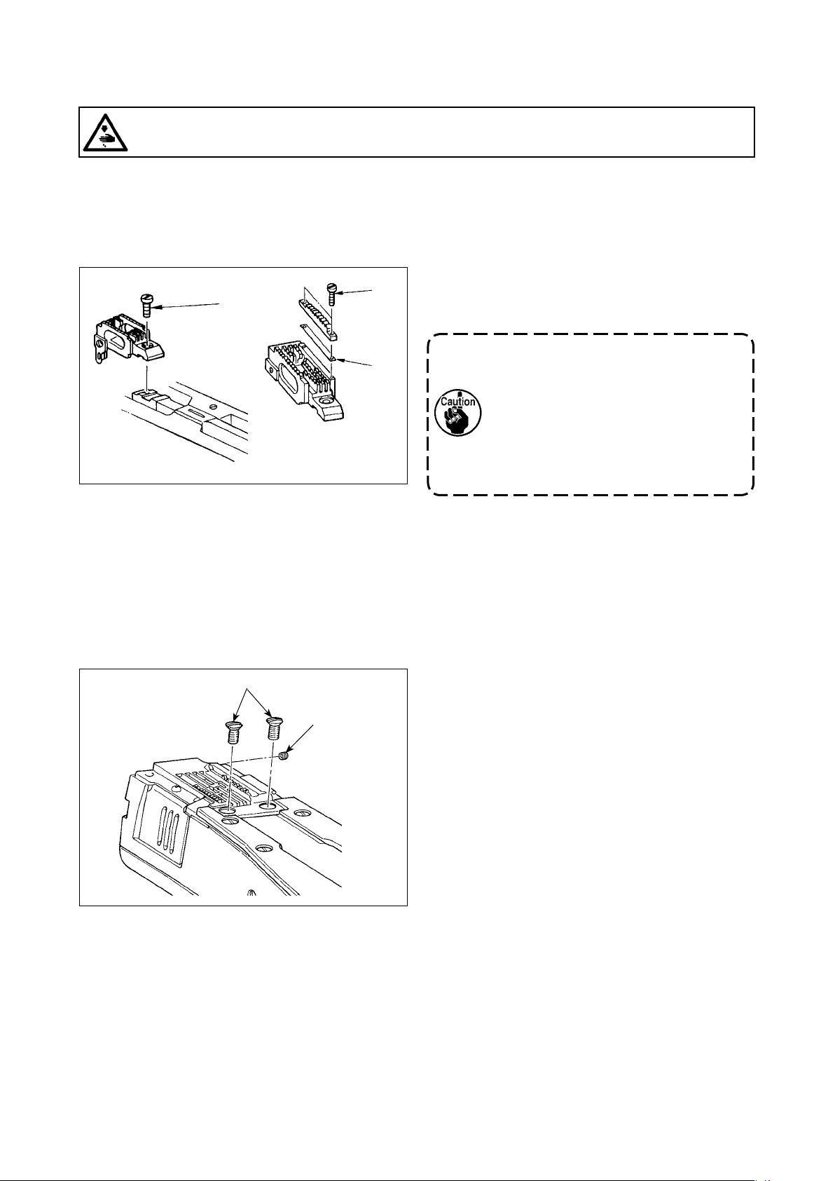
5-1. Oil quantity in the oil tank ................................................................................................. 71
5-2. Lubricating the chain off thread cutter ............................................................................ 71
5-3. Changing the cloth puller belt .......................................................................................... 72
5-4. Cleaning ............................................................................................................................. 73
5-5. Replacing the fuse ............................................................................................................. 74
ii
Page 4
1. SPECIFICATIONS
1-1. Specications of the sewing machine head
MS-1261A DWS
Sewing material type
Space
M Heavy-weight materials
Needle gauge
F 6.4mm(1/4)
Model MS-1261A△DWS MS-1261AM△DWS
Application For heavy- to extra-heavy-weight materials For medium- to heavy-weight materials
Max. sewing speed 5500 sti/min
Number of needle 3
Needle UY×128GAS #16 to 22
Cloth puller system Electronic control
Height of presser foot 10 mm
Stitch length 1.4 to 4.2 mm
Needle gauge 6.4 mm(1/4)
Circumference of cylinder 194 mm
Lubricating oil JUKI NEW DEFRIX OIL No. 1 or JUKI CORPORATION GENUINE OIL 7
Noise
Extra heavy-weight materials
(standard)
UY×128GAS #16 to 21
(Standard #21
- Equivalent continuous emission sound pressure level (LpA) at the workstation:
A-weighted value of 84.5 dB ; (Includes KpA = 2.5 dB) ; according to ISO 10821- C.6.2
-ISO 11204 GR2 at 4,500 sti/min.
- Sound power level (LWA);
A-weighted value of 91.0 dB; (Includes KWA = 2.5 dB); according to ISO 10821- C.6.2
-ISO 3744 GR2 at 4,500 sti/min.
)
(Standard #19
)
1-2. Specications of the control box
Supply
voltage
Frequency 50Hz/60Hz 50Hz/60Hz 50Hz/60Hz
Operating
environment
Input 820VA 820VA 680VA
Temperature : 0 to 35˚C
3-phase
220 to 240V
Humidity : 90% or less
Single phase
220 to 240V
Temperature : 0 to 35˚C
Humidity : 90% or less
– 1 –
Single phase
220 to 240V CE
Temperature : 0 to 35˚C
Humidity : 90% or less
Page 5
2. SETUP
2-1. Setting up the sewing machine
Fix the sewing machine on the oor with adjuster
bolts ❶ (four pieces).
❶
Be sure to move the sewing machine with two or more persons.
❶
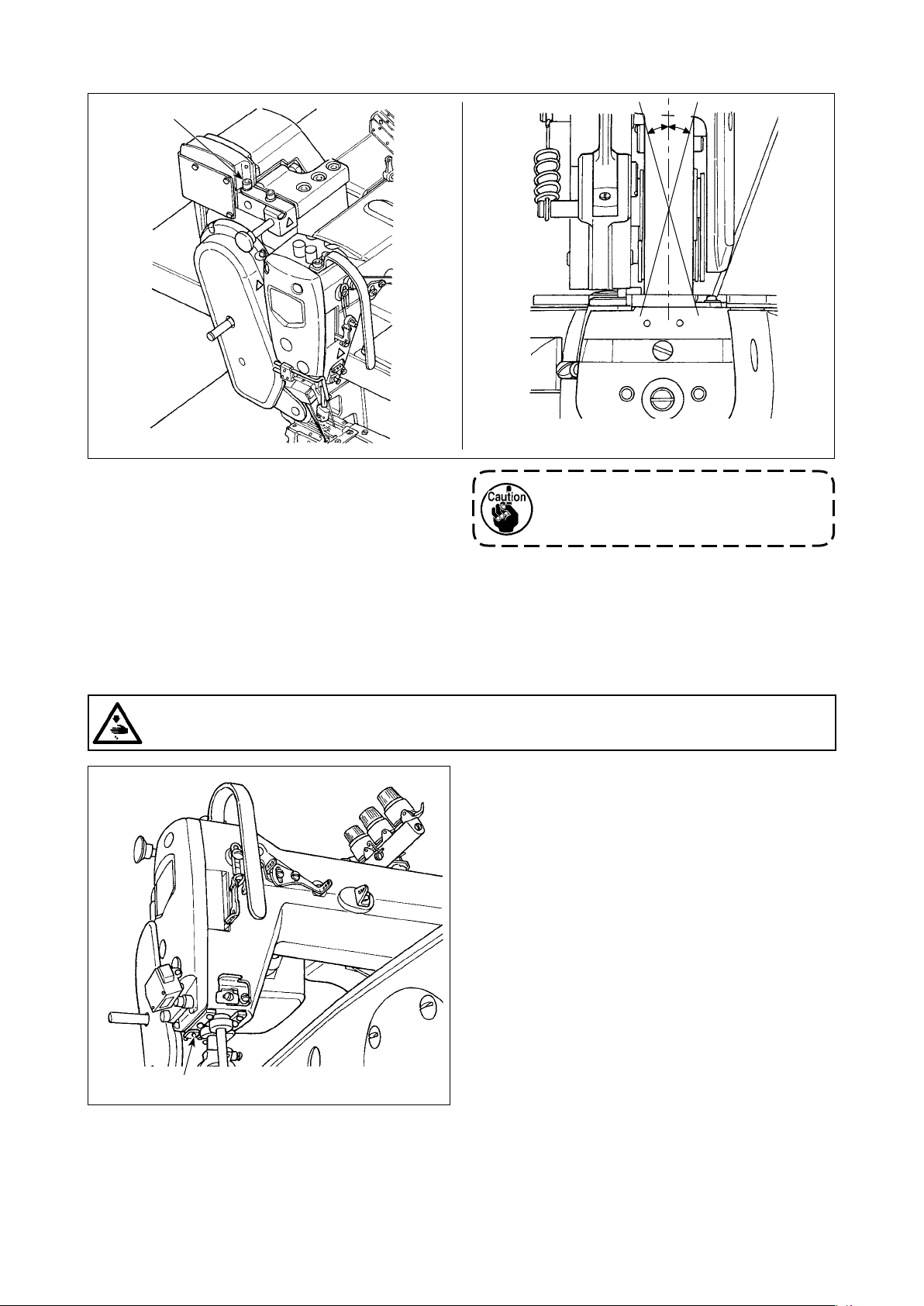
2-1-1. Adjusting the sewing machine head
Loosen bolts ❶ (four pieces) and adjust the height of sewing machine.
1. Total weight of the sewing machine, machine table and control box is 110 kg or more. It is
necessary to adjust the sewing machine height with four or more persons.
2. Adjust the sewing machine height so that it is levelled.
❶
❶
– 2 –
Page 6
2-1-2. Changing the position of the operation panel
The operation panel has been installed on the undersurface of the sewing machine table at the time of deliv-
ery. When you install it on the top surface of the sewing machine table, it is necessary to pass panel cord ❶
through hole ❸ in the lower section of motor cover ❷.
At the time of shipment
(undersurface of the sewing machine table)
In the case of changing the position of the operation
panel to the top surface of the sewing machine table
❶
❷
❸
❶
2-2. Installing the thread stand
1) Assemble the thread stand device. Fit it
in the hole in the table. Tighten locknut
so that the thread stand does not uc-
❶
tuate.
2) Fix thread stand bracket ❷ on the table
with wood screw ❸.
❸
❷
❶
❸
❷
– 3 –
Page 7
H
L
2-3. Oiling and draining of oil
Before putting your sewing machine into use, ll the oil tank with the oil supplied with the sewing machine.
1) Feeding oil
❶
A
Fill the oil tank with the aforementioned oil until
the oil surface reaches between two indicator
lines (upper marker line A and lower marker line
). After lling the oil tank, be sure to t oil sight
B
window ❶ back to its home position.
Detach oil sight window ❶.
Put JUKI New Defrix Oil
No. 1 or JUKI CORPORA-
TION GENUINE OIL 7 into
the oil tank through the oil
hole.
B
2) Draining the oil and changing the oil
Firstly, loosen wood screws ❶ (three pieces). Detach oil tank cover ❷. Then, loosen screw ❸. Discharge
the oil remaining in the oil tank completely. After discharging the oil, be sure to tighten screw ❸.
In order to increase durability of the sewing machine, it is recommended to change the oil with new oil af-
ter the rst four weeks have passed since the rst use of the sewing machine, then carry out an oil change
at an appropriate interval.
The waste oil must be disposed of properly according to the relevant laws and regulations in
your area.
❶
❷
❸
❶
– 4 –
Page 8
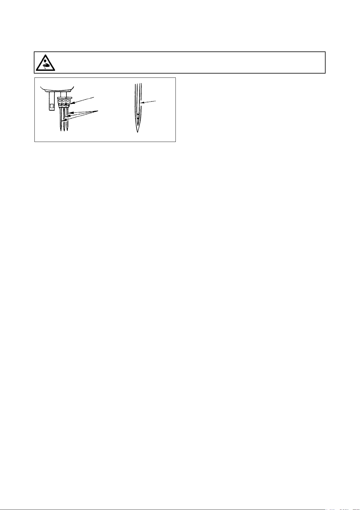
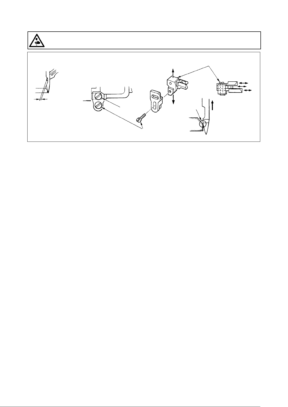
3. PREPARATION BEFORE SEWING
3-1. Attaching the needle
WARNING :
Turn OFF the power before starting the work so as to prevent accidents caused by abrupt start of the
sewing machine.
❷
❶
Long
groove
Make a choice of the needle count in accordance
with thickness of the thread and type of the material
to be used.
1) Turn the hand wheel until the needle bar reaches
to the highest position of its stroke.
2) Loosen screw ❷ in the needle clamp, and turn
needles ❶ so that the long groove on the respec-
tive needles is brought in front of you.
3) Insert the needles into the needle clamp hole until
they will go no further.
4) Securely tighten needle clamp screw ❷.
– 5 –
Page 9
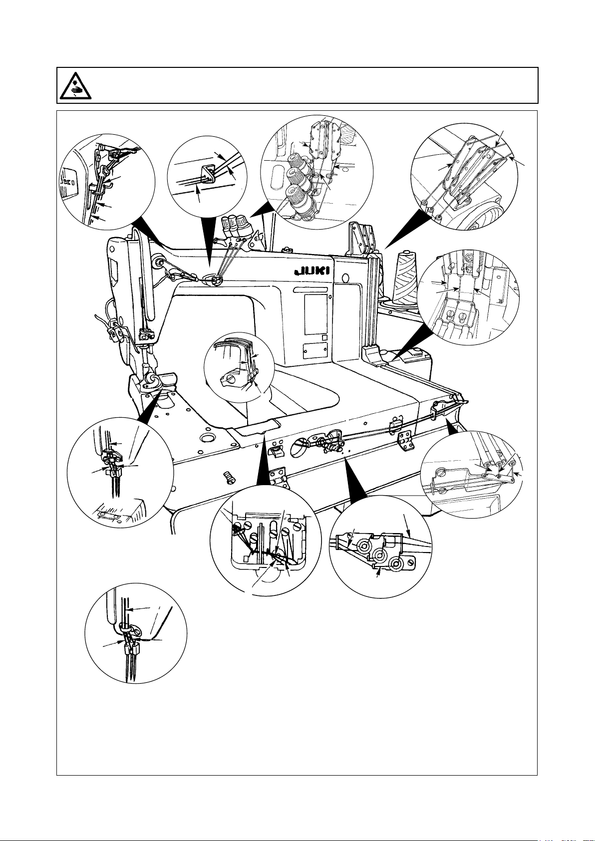
3-2. Threading the machine head
WARNING :
Turn OFF the power before starting the work so as to prevent accidents caused by abrupt start of the
sewing machine.
c
③
a
b
c
②
a
a'
c
❶
c'
❶
a
b
b
b'
①
b'
a'
❷
❷
c'
MA-1261A
c
MA-1261AM
c
a'
c'
❻
b'
b
a
b'
a'
c'
④
❺
c'
b
a
b'
a'
a'
b'
c'
❹
❸
④
Pass the needle thread on the sewing machine head in numerical order form ①.
Pass the looper thread on the sewing machine head in numerical order from ❶.
a = Right-hand needle thread b = Intermediate needle thread c = Left-hand needle thread
a' = Right-hand looper thread b' = Intermediate looper thread c' = Left-hand looper thread
– 6 –
Page 10
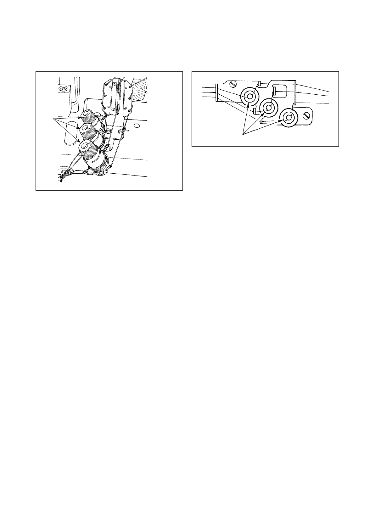
3-3. Adjusting the thread tension
1) Adjusting the needle thread tension
❶
Turn thread tension nut ❶ clockwise to increase or
counterclockwise to reduce the needle thread ten-
sion.
2) Adjusting the looper thread tension
❷
Turn tension adjusting screw ❷ clockwise to in-
crease or counterclockwise to reduce the looper
thread tension.
– 7 –
Page 11
3-4. Adjusting the stitch length
WARNING :
Turn OFF the power before starting the work so as to prevent accidents caused by abrupt start of the
sewing machine.
For the stitch length, adjust it on the sewing machine alone. Then, adjust the feed amount of the cloth puller
belt. Then, nely adjust the stitch length while visually checking the nished state of sewing material.
Adjusting the stitch length of the sewing machine alone
■
1) Remove screw ❸, and loosen the lock screw in
the feed rock cam.
❸
❶
2) Lightly pressing push-button ❶, turn the hand-
wheel by hand.
3) When push-button ❶ bites, the sewing machine
will stop running.
4) In the aforementioned state, further pressing the
push-button ❶, turn the handwheel by hand.
5) Aligning the marker dot (to be used for reference)
on the handwheel with marker line ❷ on the tim-
ing belt cover, release your hand from push-button
.
❶
6) Tighten the lock screw in the feed rock cam.
7) Attach screw ❸ in place.
Lock screw
1. Never press the push-button ❶ while
the sewing machine is in operation.
2. Be sure to operate the sewing machine
after tightening the lock screw.
3. Never operate the machine with screw
❸ removed.
4. The lock screw has a locking setscrew
to prevent the screw from loosening.
The lock screw head can be damaged
if you forcefully remove it.
❷
Marker dot on the
handwheel
Stitch length 2 3 4
* The aforementioned marker dot is only a
reference. Be aware that the adjustment result
may differ with the material used.
。。 。。。 。。。。
– 8 –
Page 12
3-5. Adjusting the needle guard
WARNING :
Turn OFF the power before starting the work so as to prevent accidents caused by abrupt start of the
sewing machine.
❸
Press the
section below
MS-1261A :
0.1~0.15mm
MS-1261AM :
0.05~0.1mm
❶
❷
The needle guard has been mounted on the feed dog. It therefore necessary to adjust the needle guard
whenever the feed amount is changed.
the needle
eyelet.
(Adjusting the clearance provided between the needle and the looper)
1) Turn the hand wheel to make the top end of the looper align with the center of the needle.
2) Loosen screw ❶, move the entire unit of the needle guard to the right or left to make the needle guard
press the needle so that the clearance of 0.1 to 0.15 mm is provided between the looper and the needle.(0.05
to 0.1 mm for MS-1261AM)
(Adjusting the vertical position of the needle guard)
1) Turn the handwheel to bring the needle guard at a position where the needle guard starts pressing the
needle.
2) Loosen screw ❷, and move the entire unit of the needle guard up or down so that the needle guard is lo-
cated at a position where it does not press and deform needle thread loops (just below the needle eyelet).
(Adjusting the clearances between the respective needles and loopers)
If the clearances between the respective loopers and needles are not equal after the clearance between
each needle and looper has been adjusted by moving the entire unit of the needle guard, adjust so that the
equal clearance is provided between the respective loopers and needles following the steps described below.
1) Turn the handwheel to make the top end of the looper align with the center of the needle.
2) Loosen screw ❸, move the respective needle guards to adjust so that the equal clearance is provided
between the respective needles and loouers.
– 9 –
Page 13
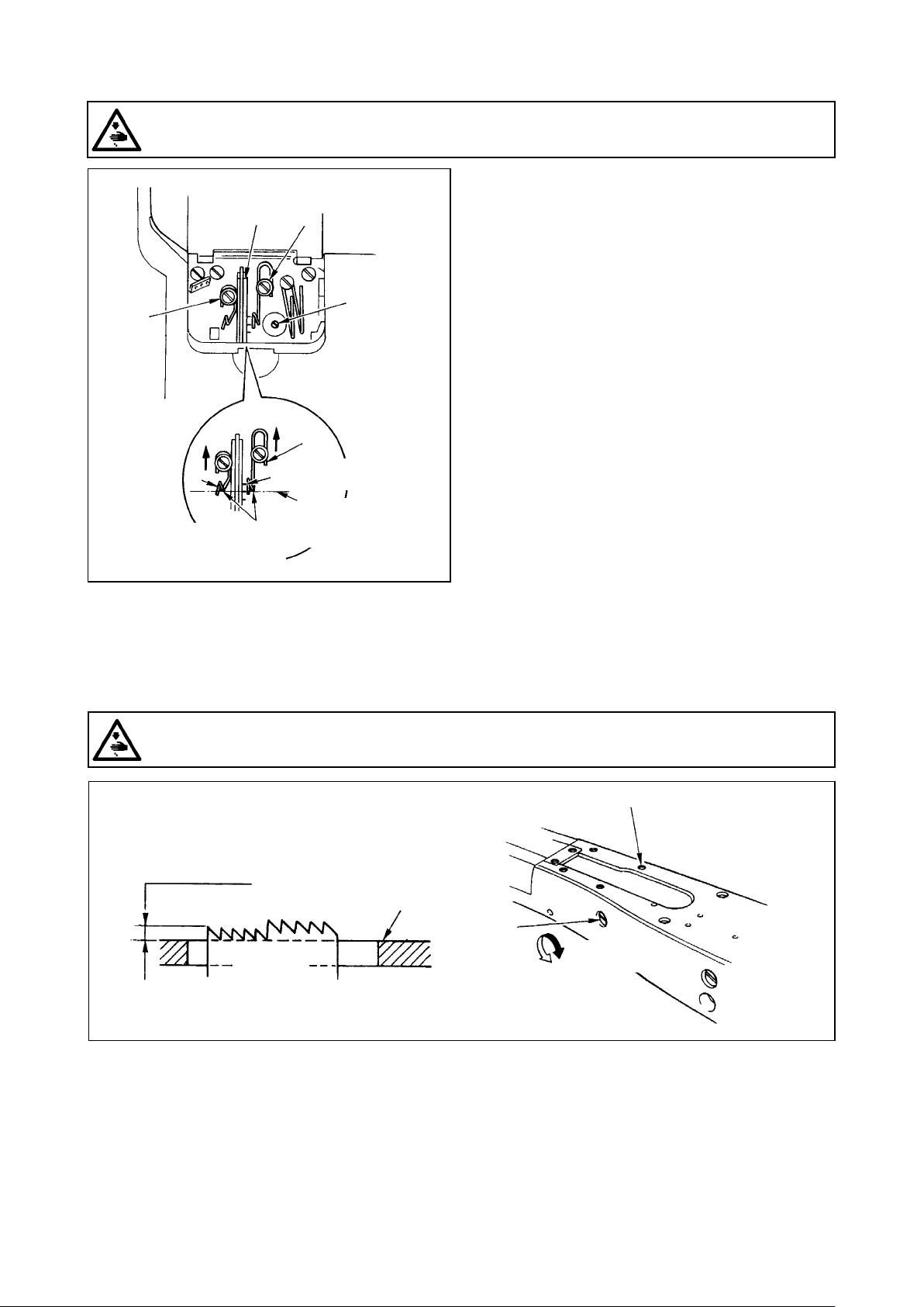
3-6. Adjusting the looper thread cam
WARNING :
Turn OFF the power before starting the work so as to prevent accidents caused by abrupt start of the
sewing machine.
❶ ❹
❷
❸
❻
❺
Align the marker line with
the bottom end of the
thread guide.
Position of the looper thread
can for cotton thread
Standard position
of the looper thread
cam
Loosen screw ❷, and adjust looper thread cam ❶
so that the looper starts drawing the thread when it
starts returning to its home position after it has pro-
jected the most.
Adjusting the looper thread cam thread guide
■
1) Align the end face of thread guide ❻ to the marker
line on thread guide ❻. Then adjust thread guide
so that its end face is ush with the end face of
❺
thread guide ❻.
The standard position of the thread guide is ob-
tained when the end face of the thread guide is
aligned with the center marker line.
2) When using a cotton thread, loosen screws ❸
and ❹, and align the end faces of thread guides
and ❻ to the marker line located far side. At
❺
this time, it is not necessary to re adjust the looper
thread cam timing.
3-7. Adjusting the feed dog height
WARNING :
Turn OFF the power before starting the work so as to prevent accidents caused by abrupt start of the
sewing machine.
❶
1.4mm
Throat plate
❷
Feed dog
Higher
The top end of the feed dog should rise 1.4 mm above the surface of the throat plate when the feed dog is in
the highest position of its stroke.
Adjusting the feed dog height
■
1) Loosen screw ❶ in the side plate of the bed and remove it.
2) Remove the screw ❶, and loosen a hexagon socket head screw under the screw ❶ with an L-shaped
hexagon wrench key.
3) Adjust the feed dog height by turning feed driving amount adjusting shaft ❷.
4) Fix the shaft with the hexagon socket head screw and tighten screw ❶.
Lower
– 10 –
Page 14
3-8. Adjusting the take-up thread tension control lever
WARNING :
Turn OFF the power before starting the work so as to prevent accidents caused by abrupt start of the
sewing machine.
Needle thread loop size is determined
by adjusting the position of take-up
❶
point dead
Needle
thread loop
❷
Lowest
MS-1261A
: 3 mm
MS-1261AM
: 0 mm
❸
2) Adjust so that, when the needle bar is in the lowest dead point, the top end of the thread tension control
lever is positioned 3 mm above the top end of thread hole in needle bar thread take-up lever ❸. (0 mm for
MS-1261AM)
3) Lowering thread tension control lever ❶ decrease the loop size. Lifting the lever increases it.
thread tension control lever ❶.
The needle thread loop size changes
in accordance with the thread and
material used. So, adjust the thread
loop size upon occasion.
1) Loosen two screws ❷, and adjust
the position of the thread take-
up lever guide by moving it up or
down.
3-9. Adjusting the position of the intermediate tension release lever and needle thread ten-
sion controller
WARNING :
Turn OFF the power before starting the work so as to prevent accidents caused by abrupt start of the
sewing machine.
Adjust the position of intermediate thread tension releasing lever ❶ and thread guide ❹ of the needle thread
tension controller as described below.
1) Turn the handwheel to bring the nee-
❷
❻
dle bar to the highest dead point.
2) Remove rubber cap ❷. Loosen
setscrew ❻ locating under the rub-
ber cap. Adjust intermediate thread
tension release lever ❶ so that the
thread coming out of intermediate
needle thread guide ❸ is horizontal.
3) Then, loosen two screws ❺, and
adjust the position of thread guide ❹
of the needle thread tension control-
ler so that the thread coming from
intermediate thread tension releasing
lever ❶ makes a beeline.
Highest dead
point
❹
❺
❶
❸
– 11 –
Page 15
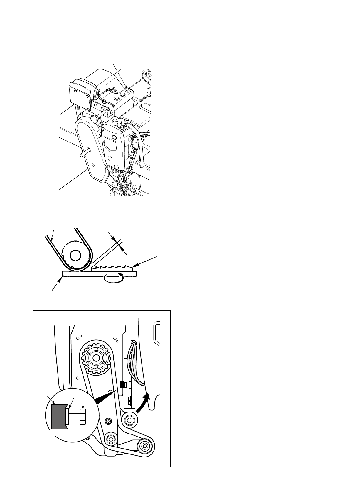
3-10. How to adjust the cloth puller
3-10-1. Adjusting the cloth puller belt and its longitudinal position
Cloth puller belt
❶
3 to 4mm
Feed dog of
the sewing
machine
(largest feed
pitch)
1) Loosen hexagon head setscrews ❶ (three piec-
es).
Maximize the feed amount of the main body of
sewing machine. Adjust the feed amount to 3 to
4 mm by moving the cloth puller back and forth
when the feed dog approaches closest to the belt.
Throat plate
❹
Slightly sinks
❷
❸
2) Loosen screw ❷ and adjust the longitudinal posi-
tion of the cloth puller so that the head of screw ❷
comes in contact with rubber ❹ to such an extent
that rubber ❹ slightly sinks.
3) Tighten nut ❸ to secure the cloth puller.
SM9051603SC
❷
NM6050003SC
❸
Cloth puller base
❹
binding part
Screw
Nut
Anti-vibration rubber
– 12 –
Page 16
3-10-2. Adjusting the inclination of the cloth puller belt
❷
1) Loosen hexagon head setscrews ❷ (two pieces).
Rotate the cloth puller so that it is in parallel with
the feed dog.
θ
θ
If the cloth puller inclines (as shown
with θ), the chain-off thread skipping
may occur.
3-11. LED hand light
WARNING :
When adjusting the sensor, neither put your hand close to the needle entry area nor put your foot on
the pedal in order to protect against injuries.
❶
* This LED is intended to improve operability
of the sewing machine and is not intended for
maintenance.
The sewing machine is provided as standard with an
LED light which illuminates the needle entry area.
Intensity adjustment and turn-off of the light is carried
out by pressing switch ❶. Every time the switch is
pressed, the light is adjusted in intensity in ve steps
and is turned off in turn.
[Change of intensity]
1
⇒
...... 4
⇒
5
⇒
1
Bright⇒...... Dim⇒Off⇒Bright
In this way, every time the switch ❶ is pressed, the
hand lamp status is changed in repetition.
– 13 –
Page 17
3-12. To use the sewing machine with a cloth puller for sewing heavy-to medium-weight ma-
terials
WARNING :
Turn OFF the power before starting the work so as to prevent accidents caused by abrupt start of the
sewing machine.
The MS-1261A has been developed to sew extra heavy-weight materials as standard. Various kinds of gauges have been prepared to enable the machine to be used for sewing heavy- to medium-weight materials. Replace the gauge, when sewing heavy- to mediumweight materials, following the procedure described below.
3-12-1. Replacing the feed dog
Remove the throat plate. Loosen screw ❶ in the
❶
❶
feed dog and remove the feed dog. Then, replace
the feed dog with an appropriate one.
Each of the feed dogs for heavy- to
❷
medium-weight materials has been
designed so that it can be used only
by replacing it without adjusting the
feed dog height. However, it is really
necessary to adjust the feed dog height,
refer to "3-7. Adjusting the feed dog
height" p. 10
3-12-2. Changing the throat plate
❶
❷
To change the height in difference on the
★
righthand side of the feed dog
Loosen two serews ❶ in the adjusting feed dog and
remove spacer ❷ (plate thickness: 0.5 mm).
Many different types of spacers are available.
Detach throat plate setscrews ❶ (two pieces) and
(one piece). Then, change the throat plate with an
❷
appropriate one.
– 14 –
Page 18
3-12-3. Adjusting the difference in height of the presser foot
Remove two screws ❷ that are used to retain ad-
justing presser foot ❶, and adjust the difference in
height of the presser foot by replacing spacer ❸.
Thicknesses of spacers that match the respective
throat plates and feed dogs are as shown in the
table.
No. Plate Thickness Specication
(Standard L: 3.5 mm)
❷
❸
❶
1 1.0mm Extra heavy-weight mate-
2 0.5mm Heavy-weight materials
3 None Medium-weight materials
To replace spacer ❸ with a spacer (0.5 mm or
none), replace screw ❷ with a shorter one (L=3.0
mm SS5060310SP).
3-12-4. Replacing the needle thread guide
rials (standard)
❶
❷
❸
When sewing a medium-weight material using a thin
thread, larger needle thread loops will be produced
and they will be likely to tilt causing stitch skipping.
To prevent the aforementioned trouble, replace
thread guide ❶ located above the needle clamp with
an appropriate one.
Loosen screw ❷ that is used to x thread guide ❶,
and replace the thread guide with thread guide ❸ for
medium-weight materials.
– 15 –
Page 19
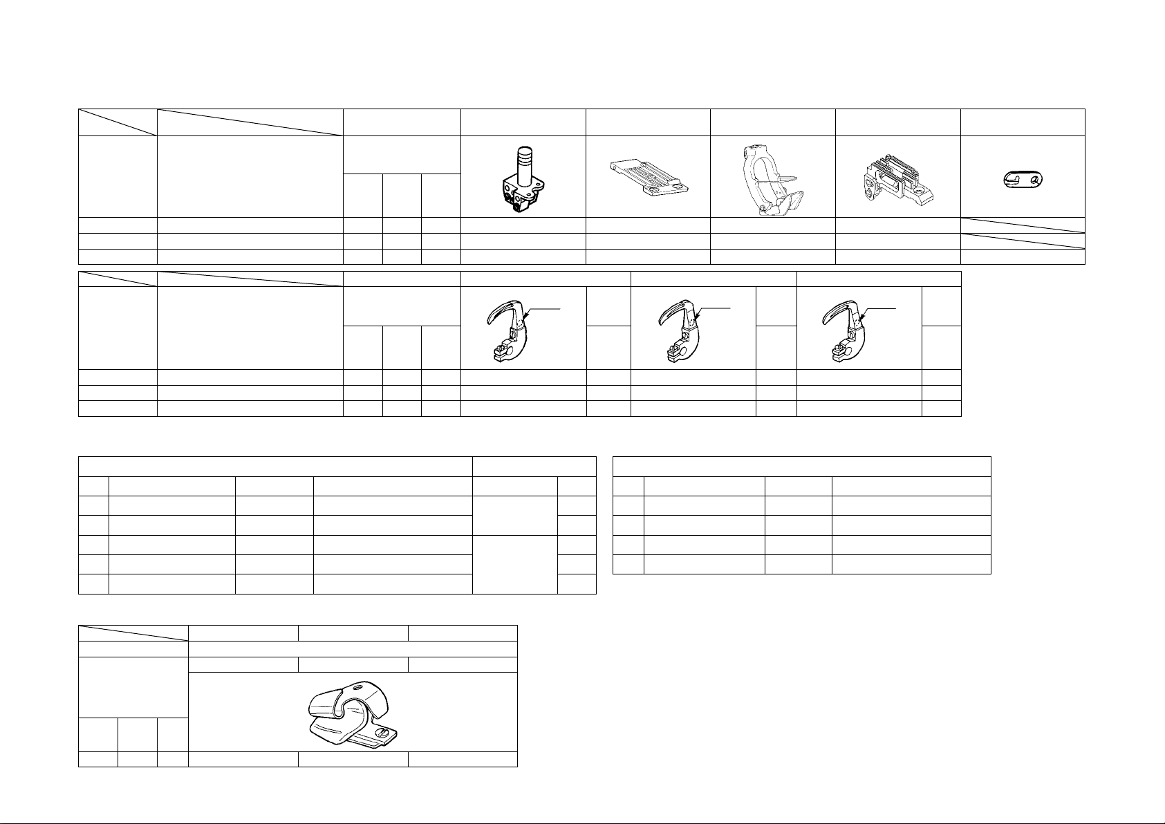
3-13. Table of replaceable gauges
Part name Needle clamp (asm.) Throat plate
Needle gauge
Model Application
Code inch mm
MS-1261A Extra-heavy-weight materials F 1/4 6.4 12956256 40202942 40202943 12963351
MS-1261A Heavy-weight materials F 1/4 6.4 12956256 40204587 40204601 12974150
MS-1261AM Medium-heavy-weight materials F 1/4 6.4 12956256 40204592 40205581 12974952 B1130051000
Part name Looper (L) (asm.) Looper (R) (asm.) Looper (C) (asm.)
Needle gauge
Model Application
Code inch mm
MS-1261A Extra-heavy-weight materials F 1/4 6.4 12968558 1 12968855 1 12969150 1
– 16 –
MS-1261A Heavy-weight materials F 1/4 6.4 12968558 1 12968855 1 12969150 1
MS-1261AM Medium-heavy-weight materials F 1/4 6.4 12968558 1 12968855 1 12969150 1
Mark
Mark
No.
Presser foot (asm.)
(with nger guard)
Mark
Mark
No.
Feed dog Needle thread guide
Mark
Mark
No.
Options
1. Spacer for presser foot 2. Setscrews
No. Plate thickness (mm) Part No. Part name Part No. Plate
①
②
③
④
⑤
0.3 12973509 Presser foot adjusting plate B
0.5 12973608 Presser foot adjusting plate C 2
0.8 12973707 Presser foot adjusting plate D
1.0 12962106 Presser foot adjusting plate A 2
1.2 12973806 Presser foot adjusting plate E 2
SS5060310SP
SS5060410SP
2
2
No. Plate thickness (mm) Part No. Part name
①
②
③
④
0.3 12975702 Feed dog adjusting plate B
0.5 12964102 Feed dog adjusting plate A
0.8 12975801 Feed dog adjusting plate C
1.0 12975900 Feed dog adjusting plate D
3. Spacer for feed dog
Folder
1 2 3
Part name Folder (asm.)
M297 M298 M299
Needle gauge
Code inch mm
F 1/4 6.4 MAM2970EEBA MAM2980BBBA MAM2990BBBA
Code of folder
M297 — For medium-weight materials
(Equipped on MS-1261AM as standard)
M298 — For heavy-weight materials (Optional)
M299 — For extra-heavy-weight materials
(Equipped on MS-1261A as standard)
Page 20
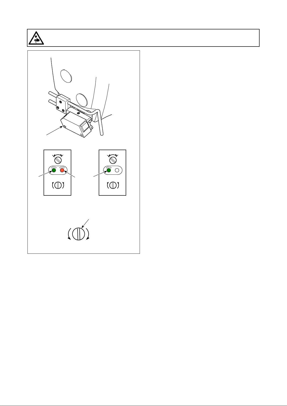
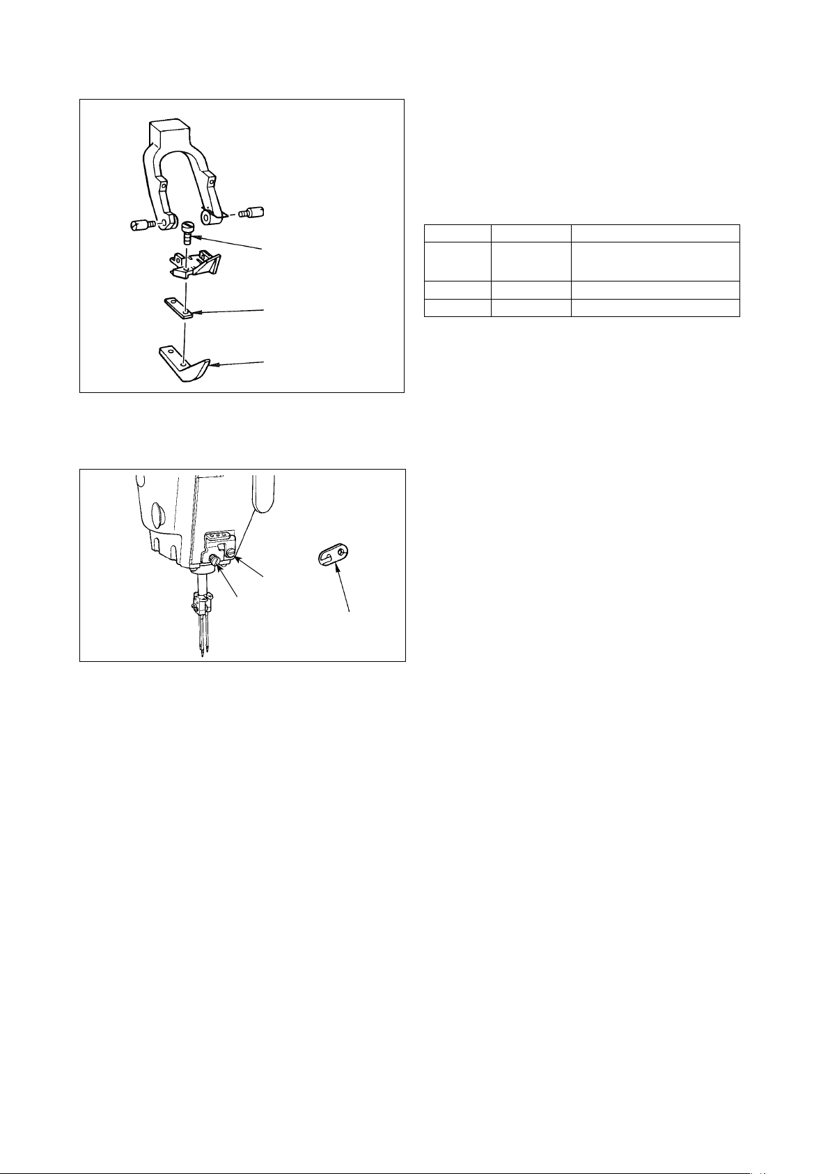
3-14. Adjusting the material edge detector
WARNING :
When adjusting the sensor, neither put your hand close to the needle entry area nor put your foot on
the pedal in order to protect against injuries.
❶
Material edge detector ❶ detects the presence /
absence of the material at the beginning and end of
sewing.
A
L
max
Material is
present
min
D
min
L
D
When the material is present, the green LED (A) and
the orange LED (B) light up at all times.
When the material is absent, only the green LED (A)
A
B
Material is
absent
max
min
lights up.
The detecting device of the sewing machine has
been factory-adjusted at the time of shipment so
❷
that it detects the presence / absence of the material
without additional adjustment. However, the detect-
ing device may fail to detect the material properly
max
depending on the type of material used.
In such a case, adjust the detecting device of the
sewing machine by turning control knob ❷.
[Adjustment procedure]
* The orange LED (B) lights up even when the ma-
terial is not present on the sewing machine.
→ Turn control knob ❷ toward the "min".
* The orange LED (B) goes out even when the ma-
terial is present on the sewing machine.
→ Turn control knob ❷ toward the "max".
– 17 –
Page 21
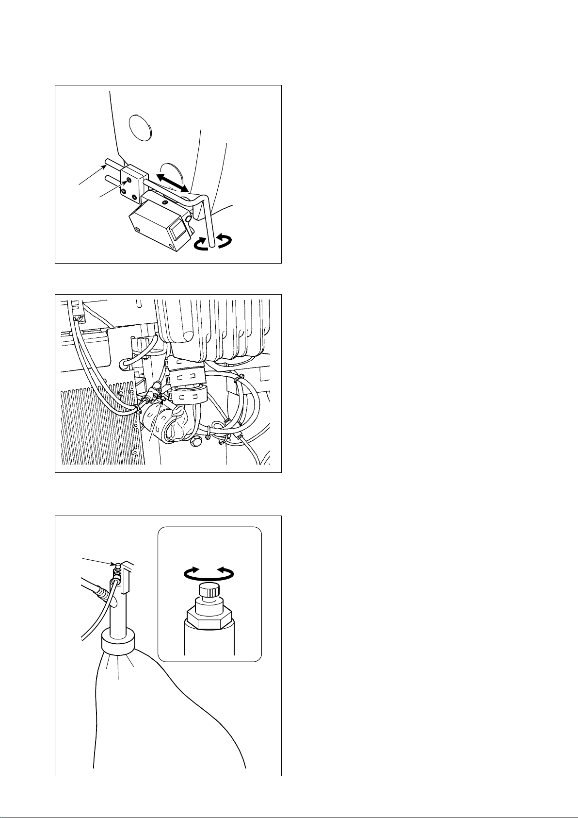
3-15. Needle cooler
3-15-1. Adjusting the position of the blow pipe
❷
❶
3-15-2. Adjusting the air ow
1) Loosen screw ❶.
2) Adjust the position of blow pipe ❷in terms of the
longitudinal direction and rotational direction.
3) Tighten screw ❶ to secure blow pipe ❷.
Adjust the air ow of the needle cooler by turning
speed controller knob ❶. Turn the speed controller
knob clockwise to decrease the air ow or counter-
clockwise to increase it.
❶
3-16. Chain-off thread cutter (suction of thread waste)
Adjust the air ow of the needle cooler by turning
speed controller knob ❶. Turn the speed controller
knob clockwise to decrease the air ow or counter-
clockwise to increase it.
❶
To
decrease
To
increase
– 18 –
Page 22
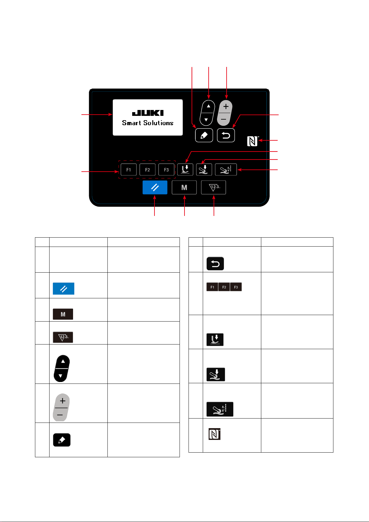
4. HOW TO USE THE OPERATION PANEL
4-1. Explanation of the operation panel switch
❼
❺
❻
❶
❾
❷
No. NAME FUNCTION
LCD display Various data such as pat-
❶
tern No., shape, etc. are
displayed.
RESET key Press this key to reset
❷
the error or reset the
counter(s), etc.
MODE key This key is used for dis-
❸
playing the mode screen.
COUNTER key This key selects counter
❹
display.
ITEM SELECT key This key is used to select
❺
the data No. and other
kinds of data.
DATA CHANGE key This key is used to change
❻
the pattern No. and other
kinds of data.
EDIT key This key is used to display
❼
the edit screen, to select
the item or to display the
detail screen.
❽
❹❸
No. NAME FUNCTION
RETURN key This key is used to return
❽
the screen to the previous
one.
F key When data or function is
❾
registered to the F key,
the registered data or the
function can be used by
pressing the F key.
Presser foot pres-
sure key
Cloth puller pressure
key
Cloth pulling amount
key
NFC mark Bring the tablet or smart-
Sewing data about the
presser foot pressure is
displayed by pressing this
key.
Sewing data about the
cloth puller pressure is
displayed by pressing this
key.
Sewing data about the
cloth pulling amount is
displayed by pressing this
key.
phone close to the NFC
mark when carrying out
communication.
– 19 –
Page 23
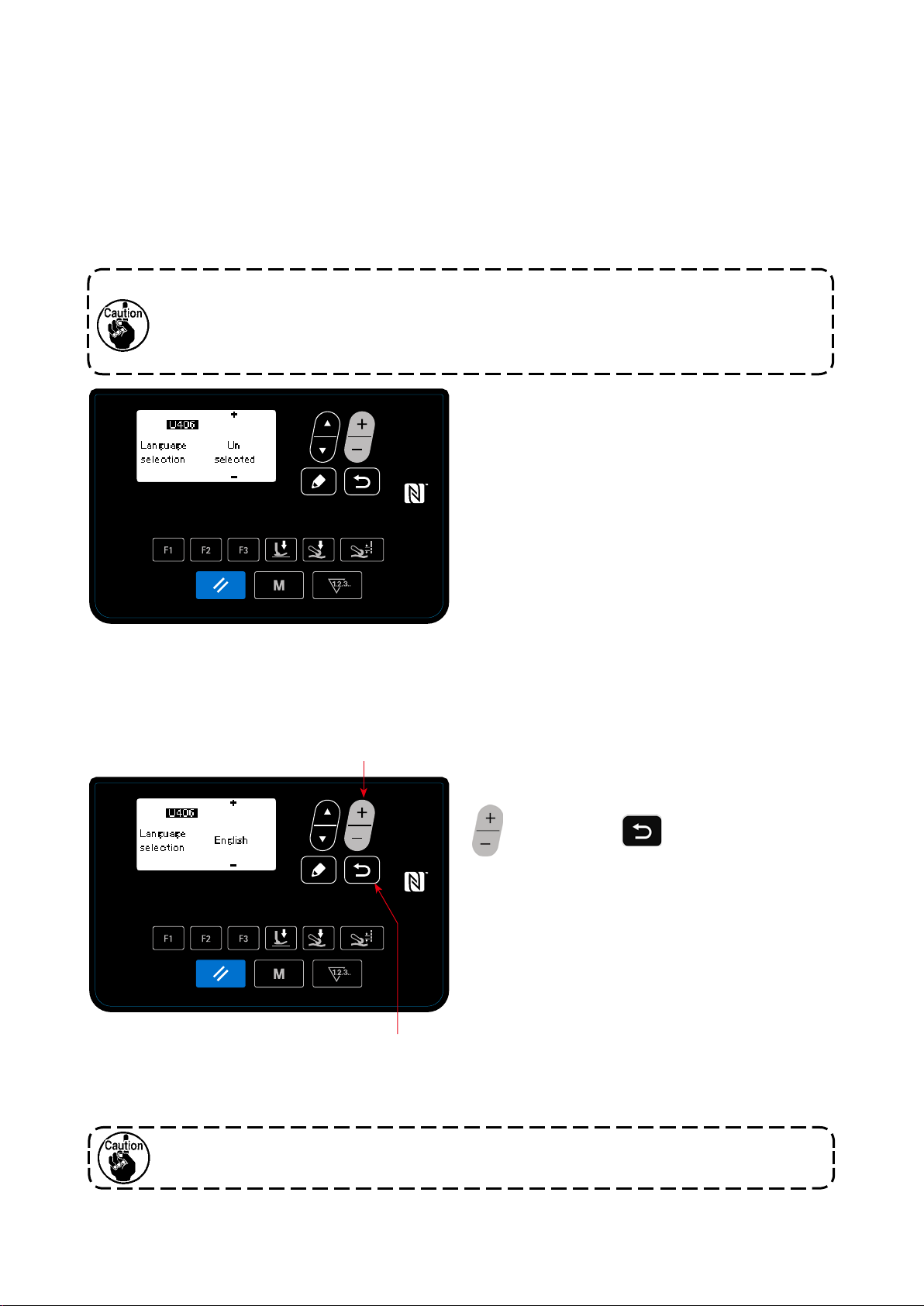
4-2. Operation to be done at rst
4-2-1. Selection of the language
Select the language to be displayed on the operation panel when you turn ON the power to your sewing
machine for the rst time after the purchase. Note that, if you turn the power OFF without selecting the
language, the language selection screen will be displayed every time you turn ON the power to the sewing
machine.
Turning ON the power switch
①
Be aware that the needle bar moves automatically when you turn ON the power to the sewing
machine for the rst time after the purchase. It is also possible to prevent the needle bar from
moving automatically using the memory switch U090. Refer to "4-5-1. Memory switch data" p.
45 for details.
When you turn ON the power switch, the language
selection screen is displayed.
<Language selection screen>
Selecting the language
②
❻
Select the language you want to use for display with
. Then, press
❻
to nalize your selec-
❽
tion of the language.
❽
The language to be displayed on the operation panel can be changed using the memory switch U406.
Refer to
"4-5-1. Memory switch data" p. 45
for details.
If you do not select your language for display, English will be used for display as default.
– 20 –
Page 24
When you turn ON the power to the sewing machine, the sewing screen for the pattern that is currently se-
lected is displayed.
This sewing machine is able to sew free sewing patterns and step sewing patterns. As many as 99 different
sewing patterns can be created by combining free sewing patterns and step sewing patterns.
In the case of a free sewing pattern, different sewing conditions can be adopted respectively for sewing at
sections and multi-layered sections of material.
In the case of a step sewing pattern, separate sewing conditions can be adopted for sewing a material on a
step-by-step basis.
The below-stated section of this Instruction Manual describes the free sewing patterns. Refer to
to edit a step sewing pattern" p. 34
for the description about step sewing patterns.
C
"4-4-6. How
J
A
B
D
Sewing screen <Free sewing pattern>
Display Content
Pattern No. Pattern No. that is being selected is displayed. (No. 1 to No. 99)
A
*1
*1
Cloth pulling amount is displayed.
*1
Cloth puller pressure is displayed.
Sewing speed is displayed.
Stitch length set with the memory switch S003 is displayed.
*1
Presser foot pressure is displayed.
State of the material placed under the cloth puller is displayed.
Top end of
material
Cloth pulling amount
B
Cloth puller pressure
C
Sewing speed
D
Stitch length
E
Presser foot pressure
F
State of the material
G
under the cloth puller
*3
E
Flat section
F
Multi-layered
section begins
I
G
H
No material
Cloth puller is
not used
State of the material
H
under the presser foot
Simple-locked state ON / OFF of the simple lock is displayed.
I
Part number / process or
J
comment
State of the material placed under the presser foot is displayed.
Top end of
material
Part number is displayed on the upper line and the process is displayed on the low-
er line. Or, comment is displayed on two lines (upper and lower lines). (Content of
display, i.e., the "part number and process" or the "comment", can be changed over
with the memory switch U404. Refer to
details).
Flat section
Multi-layered
section be-
– 21 –
gins
During the
multi-layered
section of mate-
rial
"4-5-1. Memory switch data" p. 45
End of the
multi-layered
section of mate-
rial
No ma-
terial
for
Page 25
*1 Cloth pulling amount, the cloth puller pressure, sewing speed and the presser foot presser can be set using
the sewing data items given below according to the state of the material placed under the presser foot.
State of the material
under the presser foot
Flat section
End of the
multi-layered
section of
material
Multi-layered
section begins
During the
multi-layered
section of
material
No material
Top end of
material
/
Cloth pulling amount Cloth puller pressure Sewing speed Presser foot pressure
S006
Cloth pulling amount
S015
Cloth pulling amount
when the presser
foot runs on the
multi-layered section
S019
Cloth pulling amount
for sewing the
multi-layered section
S072
Cloth pulling amount
when detecting no
material
(In the case the
material under the
cloth puller is at
section, the cloth
pulling amount set
with S006 will be
employed.)
S072
Cloth pulling amount
when detecting no
material
S007
Cloth puller pressure
S016
Cloth puller pressure
when the presser foot
runs on the multi-layered section
S020
Cloth puller pressure for sewing the
multi-layered section
S073
Cloth puller pressure
when detecting no
material
(In the case the material under the cloth
puller is at section,
the cloth pulling puller
pressure set with S007
will be employed.)
S073
Cloth puller pressure
when detecting no
material
S004
Limit of sewing
speed
S012
Multi-layered section
sewing speed
S052
Limit to the sewing
speed to be applied
after the detection of
absence of material
(While the sewing
machine is at rest,
the highest one of
four sewing speeds
shown in the table is
displayed.)
S031
Sewing speed for
starting sewing of the
top end of material
S005
Presser foot pressure
S018
Presser foot pressure for sewing the
multi-layered section
S005
Presser foot pressure
S032
Presser foot pressure
for starting sewing of
the top end of material
It should be noted, however, that the presser foot pressure, cloth pulling amount and the cloth puller pressure can
be set as sewing data as described below according to the condition of material placed under the cloth puller.
State of the material
placed under the
cloth puller
Multi-layered section
begins
Top end of
material
No material
Refer to "4-4-8. List of sewing data" p. 39 for details of sewing data items to be used in the respective
states of the material.
Presser foot pressure Cloth pulling amount Cloth puller pressure
S078
Presser foot pressure when
the cloth puller runs on the
multi-layered section
(The presser foot pressure will
be as given in the table shown
above.)
(The presser foot pressure will
be as given in the table shown
above.)
S070
Cloth pulling amount when
the cloth puller runs on the
multi-layered section
S076
Cloth pulling amount when
the cloth puller runs on the
multi-layered section
S072
Cloth pulling amount when
detecting no material
S071
Cloth puller pressure when
the cloth puller runs on the
multi-layered section
S077
Cloth puller pressure when
the cloth puller runs on the top
end of material
S073
Cloth puller pressure when
detecting no material
– 22 –
Page 26

*2. For the sewing speed, the maximum sewing speed is limited by the set values of the stitch length and cloth
pulling amount. The set value of sewing speed before the limit is applied is displayed on the operation panel.
In the case the set value of stitch length is 3.1 mm or more: Maximum sewing speed 5000 sti/min
In the case the set value of cloth pulling amount is 4.6 mm or more: Maximum sewing speed 4000 sti/min
*3. Input the stitch length using the memory switch S003 according to the feed amount of the sewing machine. (If
this value is changed, the feed amount of the sewing machine itself will not change.)
→ Referto"4-4. How to change the sewing data" p. 24.
4-3. How to select a sewing pattern
❻
The sewing pattern can be selected by pressing
on the sewing screen.
❻
The sewing pattern can also be changed by press-
❾
Sewing screen
<
ing
❾
to which a sewing pattern has
been registered.
→
Refer to "4-5-5. How to use the F key" p. 59.
>
– 23 –
Page 27

4-4. How to change the sewing data
4-4-1. Method of changing the sewing data
❽
❼
❻❺
Calling the sewing data edit screen
①
When the
screen, the sewing data edit screen for the cur-
rently-selected sewing pattern is displayed.
Selecting the sewing data to change
②
Data you want to change can be selected by
is pressed on the sewing
❼
< Sewing data edit screen >
pressing
Changing the sewing data
③
Data can be changed by pressing
The sewing data edit screen is returned to the
sewing screen by pressing
❺
.
4-4-2. Method of selecting a specic sewing data item
When
is pressed, the sewing data edit screen is displayed according to the key pressed.
(Refer to
Screens to be displayed are as shown below:
"4-5-5. How to use the F key" p. 59
to which the sewing data has been registered,
❾
for the method of registering sewing data to the F key.)
.
❻
.
❽
,
or
❾
<Sewing screen>
– 24 –
Page 28
(1) F key
❾
<Sewing screen>
(The state the sewing data which has been registered to the F key is selected)
→
(2) Presser foot pressure key
<Sewing screen>
S005
Presser foot
pressure
<Sewing data edit screen>
S018
Presser foot pressure
for sewing the multi-lay-
ered section
< Sewing data edit screen >
S032
Presser foot pressure
for starting sewing of
the top end of material
S078
Presser foot pressure when
the cloth puller runs on the
multi-layered section
(3) Cloth puller pressure key
<Sewing screen>
S007
Cloth puller
pressure
S016
Cloth puller pres-
sure when the
presser foot runs
on the multi-lay-
ered section
Cloth puller pres-
sure for sewing
the multi-layered
(4) Cloth pulling amount key
<Sewing screen>
S020
section
< Sewing data edit screen >
S071
Cloth puller pressure
when the cloth puller
runs on the multi-lay-
ered section
S073
Cloth puller pres-
sure when detect-
ing no material
S077
Cloth puller pres-
sure when the cloth
puller runs on the
top end of materia
l
S006
Cloth pulling
amount
S015
Cloth pulling
amount when the
presser foot runs
on the multi-lay-
ered section
S019
Cloth pulling
amount for sewing
the multi-layered
section
< Sewing data edit screen >
S070
Cloth pulling amount
when the cloth puller
runs on the multi-lay-
ered section
– 25 –
S072
Cloth pulling
amount when de-
tecting no material
S076
Cloth pulling amount
when the cloth puller
runs on the top end
of material
Page 29
4-4-3. How to change the part number, process or comment for the sewing pattern data
Part number, process or comment can be entered to allow the operator to easily understand the application
of sewing pattern.
The method to enter a part number is described below. Same method applies when entering a process or
comment.
❽
❼
❻❺
Calling the part number setting screen
①
The part number setting screen is displayed by
❷
< Part number setting screen >
pressing
ber" on the sewing data edit screen.
Entering the part number
②
The place (what character number) at which a
part number is entered can be selected by press-
ing
number) can be entered at that place by pressing
One of the entered characters that is selected can
be deleted by
can be deleted by keeping reset key held pressed
for one second.
When
returns to the sewing data edit screen.
Characters that can be entered
A - Z, 0 - 9, ., +, -, /, #, (line feed), (blank)
❻
❺
.
after selecting "S061 Part num-
❼
. Characters (representing the part
. All entered characters
❷
is pressed, the current screen
❽
Whether the part number / process or the comment is displayed can be changed with the
memory switch U404. Refer to "4-5-1. Memory switch data" p. 45 for details.
– 26 –
Page 30
4-4-4. How to carry out teaching of the multi-layered section of material
It is possible to perform teaching of the thresholds of the lower part (thinner part) and of the upper part (thicker
part) of multi-layered section of material while using the actual sewing product.
Sewing data items that can be used for teaching are as follows:
Sewing pattern that is currently selected Sewing data that can be used for teaching
Free sewing patter S011 Multi-layered section changeover sensor ON value
S021 Multi-layered section changeover sensor OFF value
Step sewing pattern "S103 Step changeover" sensor *
* "S103 Step changeover sensor value" can only be selected in the case "S101 Step changeover" is set to the
material thickness sensor value.
❼
Teaching of the multi-layered section starts and
①
the teaching screen for the lower part of multi-lay-
ered section is displayed by pressing edit key
after selecting the aforementioned data
❼
on the sewing data edit screen.
< Teaching screen
for the lower part of multi-layered section >
❼
❽
Teaching screen for the upper part of multi-layered
②
section is displayed by pressing edit key
after placing the lower part of multi-layered section
under the presser foot.
Teaching screen returns to the sewing data edit
③
screen by pressing edit key
after placing
❼
the upper part of multi-layered section under the
presser foot.
Value of the data selected in the aforementioned 1)
< Teaching screen
for the upper part of multi-layered section >
will be automatically changed to the intermediate
value between the thickness of lower part and that
of upper part of multi-layered section.
1. When the pedal is depressed during teaching of the multi-layered section of material, the
sewing machine operates. It is convenient to depress the pedal to feed the material until the
upper part of multi-layered section is brought to the presser foot after having carried out
teaching of the lower part of multi-layered section.
❼
2. If the
the teaching of the multi-layered section of material and the screen will return to the sewing
data edit screen.
3. If the feed dog appears above the throat plate in the aforementioned ② or ③, the
cannot be operated.
4. Be aware that the sensor may detect the multi-layered section of material by mistake by
excessively decreasing the aforementioned data value.
is pressed in the aforementioned ② or ③, the sewing machine will quit from
❽
❼
– 27 –
Page 31

4-4-5. Sewing data on a free sewing pattern
The following sewing data are used in each sewing state of a free sewing pattern.
Top-of-material sewing
①
Setting of the sewing data to be used from the time
at which the material is detected to the time at which
the top of material reaches the cloth puller is carried
out.
State display on the operation panel:
The following data items are used.
S031 Sewing speed for starting sewing of the top end of material
← (When the sewing machine completes sewing of "S033 The number of stitches at which the sew-
ing speed is changed at the beginning of sewing the top of material", the sewing state shifts to "S004
Sewing speed.")
S032 Presser foot pressure for starting sewing of the top end of material
S073 Cloth puller pressure when detecting no material
S072 Cloth pulling amount when detecting no material
S033 Number of stitches for changing the sewing speed for starting sewing of the top end of material
S034
* If the material cannot be fed consistently from the time at which the material is detected to the time
When the sewing machine completes sewing of "S034 The number of stitches at which the presser foot
pressure is changed at the beginning of sewing the top of material" in the "top of material sewing state", the
sewing state shifts to "Flat section state."
Number of stitches for changing the presser foot pressure for starting sewing of the top end of material
at the top of material reaches the cloth puller, change the setting appropriately.
Flat section
②
State display on the operation panel:
The following data items are used.
S004 Limit of sewing speed
S005 Presser foot pressure
S007 Cloth puller pressure
S006 Cloth pulling amount
When the sewing machine completes sewing of "S074 The number of stitches from which the cloth puller
runs on the top of material" from the beginning of sewing of the top of material (①), the sewing state shifts
to the "cloth puller runs on the top of material".
– 28 –
Page 32
Cloth puller runs on the top of material
③
Setting of the sewing data to be used when the top
of material is fed to reach the cloth puller is carried
out.
State display on the operation panel:
* Depending on the "S034 The number of stitches
at which the presser foot pressure is changed at
the beginning of sewing the top of material" and
the "S074 The number of stitches from which the
cloth puller runs on the top of material", the state
of the presser foot side may remain in the "state
of sewing the top end of material".
Parameter
S004 Limit of sewing speed
S005 Presser foot pressure
S077 Cloth puller pressure when the cloth puller runs on the top end of material
S076 Cloth pulling amount when the cloth puller runs on the top end of material
S074 Number of stitches at which the cloth puller starts running on the top end of material
S075 Number of stitches while the cloth puller runs on the top end of material
S005 Presser foot pressure
S007 Cloth puller pressure
S006 Cloth pulling amount
* If the top of material is caught in the cloth puller, change the setting appropriately.
When the sewing machine completes sewing of "S075 The number of stitches at which the cloth puller runs
on the top of material" in the "state the cloth puller runs on the top of material", the sewing state shifts to the
"at section state".
While the sewing machine sews a at section of material
④
Setting of the sewing data for normal sewing is car-
ried out.
State display on the operation panel:
The following data items are used.
S004 Limit of sewing speed
S005 Presser foot pressure
S007 Cloth puller pressure
S006 Cloth pulling amount
When the measured value by the multi-layered section sensor reaches the "S011 Multi-layered section
changeover sensor ON" value or more, the sewing state shifts to the "state of running on the multi-layered
section".
* The multi-layered section detection timing can be advanced by decreasing the "S011 Multi-layered
section changeover sensor ON" set value. Be aware, however, that false detection of the multi-layered section can occur if the timing is advanced excessively.
– 29 –
Page 33
State the sewing machine runs on the multi-layered section of material
⑤
Setting of the sewing data to be used from the time
at which a multi-layered section of material is detect-
ed to the time at which the the presser foot of the
sewing machine completely runs on the multi-lay-
ered section is carried out.
State display on the operation panel:
The following data items are used.
S012 Multi-layered section sewing speed
S005 Presser foot pressure
S016 Cloth puller pressure when the presser foot runs on the multi-layered section
S015 Cloth pulling amount when the presser foot runs on the multi-layered section
S011 Multi-layered section changeover ON sensor value
S013 Number of stitches when the presser foot runs on the multi-layered section
After the sewing machine completes sewing of "S013 The number of stitches to be sewn when running on
the multi-layered section" in the "state of the sewing machine runs of the multi-layered section of material",
the sewing state shifts to the "state of sewing the multi-layered section of material".
Set "S013 Number of stitches to be sewn when running on the multi-layered section" according to the length
and shape of the multi-layered section of material.
State of sewing the multi-layered section of material
⑥
Setting of the sewing data to be used after the press-
er foot of the sewing machine completely runs on the
the multi-layered section of material is carried out.
State display on the operation panel:
The following data items are used.
S012 Multi-layered section sewing speed
S018 Presser foot pressure for sewing the
multi-layered section
S020 Cloth puller pressure for sewing the multi-lay-
ered section
S019 Cloth pulling amount for sewing the multi-lay-
ered section
S017 The number of stitches to be sewn on the
multi-layered section
S021 Multi-layered section changeover OFF sen-
sor value
– 30 –
Page 34

After the sewing machine completes sewing of "S017 The number of stitches to be sewn on the multi-layered
section" in the "state of sewing the multi-layered section of material", the sewing state shifts to the state of
the "end of the multi-layered section of material". (In the case the number of stitches set for "S017 The num-
ber of stitches to be sewn on the multi-layered section" is "0 (zero)", the sewing states will shift to the state
of the "end of the multi-layered section of material" when the measured value by the multi-layered section
sensor reaches the "S021 Multi-layered section changeover sensor OFF value" or less.)
Set "S017 Number of stitches to be sewn on the multi-layered section" according to the length and shape of
the multi-layered section of material
* Sewing conditions may differ according to the type of material and the condition of the multi-lay-
ered section. If the stitch gathers at the multi-layered section of material, change the settings of
sewing data to be used in ⑤ and ⑥.
The end of the multi-layered section of material
⑦
State display on the operation panel:
The following data items are used.
S004 Limit of sewing speed
S005 Presser foot pressure
S007 Cloth puller pressure
S006 Cloth pulling amount
When the measured value by the multi-layered section sensor reaches the "S011 Multi-layered section
changeover sensor ON" value or less, the sewing state shifts to the "state of the at section of material".
Flat section
⑧
State display on the operation panel:
The following data items are used.
S004 Limit of sewing speed
S005 Presser foot pressure
S007 Cloth puller pressure
S006 Cloth pulling amount
After the sewing machine completes sewing of "S068 The number of stitches at which the cloth puller runs
on the multi-layered section" from the start of running on the multi-layered section (⑤), the sewing state
shifts to the state of the "cloth puller runs on the multi-layered section of material".
– 31 –
Page 35

Cloth puller runs on the multi-layered section of material
⑨
Setting of the sewing data to be used while the cloth
puller runs on the multi-layered section of material is
carried out.
State display on the operation panel:
* Depending on the " S017 The number of stitch-
es to be sewn on the multi-layered section" and
"S068 The number of stitches at which the cloth
puller runs on the multi-layered section", the state
of the presser foot side may remain in the "state
of sewing the multi-layered section of material".
The following data items are used.
S004 Limit of sewing speed
S078 Presser foot pressure when the cloth puller runs on the multi-layered section
S071 Cloth puller pressure when the cloth puller runs on the multi-layered section
S070 Cloth pulling amount when the cloth puller runs on the multi-layered section
S068 Number of stitches at which the cloth puller starts running on the multi-layered section
S069 Number of stitches during which the cloth puller runs on the multi-layered section
* If the stitch gathering occurs at the multi-layered section of material in the cloth puller, change the
setting appropriately.
After the sewing machine completes sewing of "S069 The number of stitches during which the cloth puller
runs on the multi-layered section" in the "cloth puller runs on the multi-layered section" state, the sewing
state shifts to the state of the "at section of material".
Flat section
⑩
State display on the operation panel:
The following data items are used.
S004 Limit of sewing speed
S005 Presser foot pressure
S007 Cloth puller pressure
S006 Cloth pulling amount
When the cloth detection sensor detects "absence of material". the sewing state shifts to the "no material
state".
– 32 –
Page 36

No material
⑪
Setting of the state no material is detected is carried
out.
State display on the operation panel:
The following data items are used.
S052 Limit to the sewing speed to be applied after
the detection of absence of material
S005 Presser foot pressure
S073 Cloth puller pressure when detecting no ma-
terial
S072 Cloth pulling amount when detecting no ma-
terial
When the cloth detection sensor detects a material from the "no material state", the sewing state shifts to the
"top of material" sewing state.
(①Return to the sewing of the top end of material)
1. Regardless of the current status of sewing such as the sewing of the at section or that of
the multi-layered section of material, the sewing machine state will shift to the "no-material"
state whenever the cloth detection sensor detects the absence of material.
2. False detection of material can occur if the operator places his / her hand under the cloth
detection sensor. Take care not to place the hand under the sensor.
– 33 –
Page 37

4-4-6. How to edit a step sewing pattern
A step sewing pattern consists of 10 steps at the maximum. Different sewing conditions can be set for each
step on a step-by-step basis.
The condition to be satised to proceed to the next step can be set with "S101 Step changeover condition".
As many as 10 different step sewing patterns can be created.
Step changeover condition Details
Number of stitches When the sewing machine completes sewing of the number of stitches set with "S102
The number of stitches for step changeover", the sewing machine proceeds to the next
step.
Material thickness When the material thickness that exceeds the value set with "S103 The sensor value for
step changeover" changes to a value that is smaller than the aforementioned set value (or
the material thickness that falls below the aforementioned set value changes to a value
that is larger than the set value), the sewing machine proceeds to the next step.
Optional input When the sewing machine accepts an optional input, the sewing machine proceeds to
the next step.
Final step No further step is possible. When there is no material on the sewing machine, the sewing
machine returns to the rst step.
In the state there is no material on the sewing machine, the sewing machine will not proceed to
the next step.
BA
< Sewing screen (Step sewing pattern) >
Display Content
A
Current step The number of the current step is displayed.
B
Total number of steps The total number of steps is displayed.
C
Step changeover condition
set value
The set value for the step changeover condition is displayed. This set value is not
displayed at the nal step.
The number of stitches Material thickness sensor value Optional input
C
– 34 –
Page 38

No step sewing pattern is registered in the sewing machine at the time of purchase. It is, therefore, neces-
sary to create a step sewing pattern using one of the below-stated procedures.
(1) Changing the shape of a free sewing pattern to a step sewing pattern
❺
< Sewing pattern edit screen >
❼
❽
❽
Starting the change in shape
①
When
❺
(or
) is pressed after
❽
changing "S001 Shape" to the step sewing on
the sewing data edit screen for the free sewing
pattern, "Are you sure you want to continue? Yes /
No" message is displayed.
When
is pressed after the aforemen-
❼
tioned message is displayed, "Are you sure you
want to overwrite the pattern in use? Yes / No"
message is displayed.
If
is pressed, the change in shape is
❽
< M613 Message screen >
❼
< M614 Message screen >
❽
cancelled and the screen returns to the sewing
data edit screen.
Changing the shape
②
When
is pressed, the shape is changed
❼
to a step sewing. Then, the screen returns to the
sewing screen.
If
is pressed, the screen for selecting a
❽
pattern number with which a step sewing pattern
is newly created.
In the case there is no pattern number
with which a new pattern is created, the
message "Overwrite" message is dis-
played by pressing
When
aforementioned screen is displayed, the
screen for selecting the pattern number
of the pattern to be overwritten with a
step sewing pattern.
is pressed after the
❼
❽
.
(2) Creating a new step sewing pattern
Refer to
"4-5-3. How to copy / newly create a pattern" p. 54
for details.
– 35 –
Page 39

Displaying the step sewing pattern edit screen
①
❼
< Sewing screen (Step sewing pattern) >
Selecting the step you want to edit
②
Display the step sewing edit screen by keeping
held pressed for one second on the sew-
❼
ing screen for selecting the step sewing.
Step that is being selected
❷
< Step sewing pattern edit screen >
A step is added after the currently-selected step by pressing "+", or before the currently-selected step by
・
pressing "−" of
A step is added at the end of steps by pressing "▼" of
・
❻
❼
.
❻ ❽❺
1. Select the step by pressing
that is being selected is displayed in reverse vid-
eo.)
2.
In the case there is an unused step(s), a step(s)
can be added by following the procedure de-
scribed below.
If
will be cancelled and the sewing screen will be
displayed. (Added step is conrmed by pressing
lected.)
is pressed, the addition of a step
❽
while a step that is being added is se-
❼
while the leading step is being selected.
❺
❺
.
(The step
When "▲" of
・
added at the end of the existing steps.
3. The step that is being selected can be deleted by pressing
second, all existing steps in the sewing pattern can be deleted.
is pressed while the last step of the existing steps is being selected, a new step is
❺
– 36 –
If reset key is held pressed for one
❷ .
Page 40

Editing the selected step
③
❻❺❼
< Step sewing pattern step edit screen >
Sewing the sewing pattern you have edited
④
❽
1. When
selected, the step sewing pattern step edit screen
is displayed.
2. Select the sewing data item you want to edit by
pressing
.
❻
Refer to
details.
* When the edit key is pressed while the number of
stitches of "S102 Step changeover condition" is
being selected, the number of stitches teaching
screen is displayed. Refer to
out the teaching of the number of stitches" p.
38
"4-4-8. List of sewing data" p. 39
for the number of stitches teaching function.
is pressed while the step is being
❼
. Edit the item by pressing
❺
"4-4-7. How to carry
for
< Sewing screen (Step sewing pattern) >
When
rmed, and the screen returns to the step sewing
pattern edit screen.
The data you have set is reected on the screen.
When
returns to the sewing screen for the step sewing
pattern that has been edited.
is pressed, the edited data is con-
❽
is pressed again, the screen
❽
– 37 –
Page 41

4-4-7. How to carry out the teaching of the number of stitches
Teaching of the number of stitches is possible for a step sewing pattern in the case the number of stitches is
used as the step changeover condition.
Displaying the number of stitches teaching screen
①
❼
< Step sewing pattern step edit screen >
Starting the teaching of the number of stitches
②
A
Display the teaching screen by pressing
❼
after selecting "S102 The number of stitches for
step changeover" on the step sewing pattern step
edit screen.
Pictograph A is displayed and the operation mode
enters the teaching mode.
<The number of stitches teaching screen >
Depress the back part of pedal after completing
the sewing of a pattern (until the last stitch is
sewn). Then, the sewing machine exits from the
teaching mode and returns to the previous screen.
– 38 –
Page 42

4-4-8. List of sewing data
(1) Sewing data to be used for free sewing patterns and step sewing patterns
No. Item name Input range
S001 Shape Free sewing Step
sewing
S003 Stitch length
S004 *1Limit of sewing speed
S005 *2Presser foot pressure
S006 Cloth pulling amount
S007 *3Cloth puller pressure
S011 Multi-layered section
changeover ON sensor
value
S012 *1Multi-layered section
sewing speed
S013 Number of stitches when
the presser foot runs on
the multi-layered section
S015 Cloth pulling amount
when the presser foot
runs on the multi-layered
section
S016 *3Cloth puller pressure
when the presser foot
runs on the multi-layered
section
1.4 to 4.2mm
150 to
5500sti/min
350 to 200
–
1.2 to
5.5mm
90 to 120
–
500 to 3000
/
Multi-layered
section is not
detected
150 to
5500sti/min
0 to 200
stitches
1.2 to
5.5mm
90 to 160 -
–
Enter the stitch length according to the feed amount of
sewing machine. (The feed amount of the sewing machine will not change if this value is changed.)
‐
‐
‐
‐
- If the multi-layered section sensor value exceeds this
value, the multi-layered section is detected.
This data item is used for setting the sewing speed to be
applied from the time at which the multi-layered section
is detected to the time at which the multi-layered section
sewing ends.
This data item is used for setting the number of stitches
to be sewn from the time at which the multi-layered sec-
tion of material is detected to the time at which the entire
presser foot runs on the multi-layered section.
While the sewing machine is engaged in the sewing of
this number of stitches, the sewing machine operates
using the cloth pulling amount set with "S015" and the
cloth puller pressure set with "S016".
-
*1: The actual sewing speed is limited by "S003 Stitch length" and the set value of cloth pulling amount.
In the case the set value of stitch length is 3.1 mm or more: Maximum sewing speed 5000 sti/min
In the case the set value of cloth pulling amount is 4.6 mm or more: Maximum sewing speed 4000 sti/min
*2: If this value is set to a negative value (minus value), the presser foot will go up. If the presser foot height is set so
that it oats, the multi-layered section changeover function will be disabled.
*3: If this value is set to a negative value (minus value), the cloth puller will go up.
– 39 –
Page 43

No. Item name Input range
S017 The number of stitches to
be sewn on the multi-layered section
S018 *2Presser foot pressure for
sewing the multi-layered
section
S019 Cloth pulling amount for
sewing the multi-layered
section
S020 *3Cloth puller pressure for
sewing the multi-layered
section
S021
Multi-layered section
changeover OFF sensor
value
0 to 200
stitches
350 to 200 -
–
1.2 to
5.5mm
90 to 160 -
–
500 to 3000
Multi-layered
section is
not detected
This data item is used for setting the number of stitches
to be sewn from the time at which the presser foot runs
on the multi-layered section to the time at which the
presser foot leaves the multi-layered section. While the
sewing machine is engaged in sewing of this number of
stitches, the sewing machine operates using the presser
foot pressure set with "S018", the cloth pulling amount
set with "S019" and the cloth puller pressure set with
“S020”.
-
- When the multi-layered section sensor value falls below
this value while the sewing machine is engaged in the
sewing of the multi-layered section of material, the
sewing machine nishes the sewing of the multi-layered
section. This set value is rendered effective in the case
the number of stitches for multi-layered section (S017)
is not set (0 stitch).
S031
1
*
S032
2
*
S033
S034
S041
Sewing speed for starting
sewing of the top end of
material
Presser foot pressure for
starting sewing of the top
end of material
Number of stitches for
changing the sewing
speed for starting sewing
of the top end of material
Number of stitches for
changing the presser
foot pressure for starting
sewing of the top end of
material
Number of stitches to be
sewn from the beginning
of sewing until the chainoff thread cutter is actuated
150 to 5500sti/min
350 to 200
–
0 to 200 stitches
0 to 200 stitches
0 to 2000 stitches
This data item is used for setting the sewing speed to
be employed when the material is detected after the
state no material has been detected. In the case a cloth
sensor is not used, the speed limit by this parameter will
not be applied. In the case both this function and "U037
Soft start function" are enabled, the sewing machine will
operate using the lower sewing speed.
This data item is used for setting the presser foot pres-
sure to be applied when the material is detected after
the state no material has been detected.
This data item is used for setting the number of stitches
to be sewn with the sewing speed set with "S031 Sewing
speed for starting sewing of the top end of material".
This data item is used for setting the number of stitches
to be sewn with the sewing speed set with "S032 Sewing
speed for starting sewing of the top end of material".
This data item is used for setting the number of stitches
to be sewn from the time at which the material is detect-
ed to the time at which chain-off thread cutter is actuat-
ed.
*1: The actual sewing speed is limited by "S003 Stitch length" and the set value of cloth pulling amount.
In the case the set value of stitch length is 3.1 mm or more: Maximum sewing speed 5000 sti/min
In the case the set value of cloth pulling amount is 4.6 mm or more: Maximum sewing speed 4000 sti/min
*2: If this value is set to a negative value (minus value), the presser foot will go up. If the presser foot height is set so
that it oats, the multi-layered section changeover function will be disabled.
*3: If this value is set to a negative value (minus value), the cloth puller will go up.
– 40 –
Page 44

No. Item name Input range
S042
S043
Number of stitches
at which the chain-off
thread cutter is actuated
after the detection of
absence of material
Selection of chain-off
thread cutter operation
by a depress on the back
part of pedal
0 to 2000 stitches
Operate / Not operate
This data item is used for setting the number of stitches
to be sewn before actuating the chain-off thread cutter
after the detection of the absence of material.
This data item is used for selecting the operation of the
chain-off thread cutter when the back part of pedal is
depressed to the second level.
S051 Needle bar stop position Stop at the
upper posi-
tion
Stop at
the lower
position
S052
S053
S061
S062
S063
S068
S069
S070
S071
S072
Limit to the sewing speed
to be applied after the
1
*
detection of absence of
material
Needle-cooler ON delay
number of stitches
Part number
Process
Comment
Number of stitches at
which the cloth puller
starts running on the
multi-layered section
Number of stitches during
which the cloth puller
runs on the multi-layered
section
Cloth pulling amount
when the cloth puller
runs on the multi-layered
section
Cloth puller pressure
when the cloth puller
3
*
runs on the multi-layered
section
Cloth pulling amount
when detecting no material
150 to 5500sti/min
0 to 200 stitches
0 - 24 characters
0 - 24 characters
0 - 50 characters
0 to 200
stitches
0 to 200
stitches
1.2 to
5.5mm
90 to 120 -
–
1.2 to 5.5mm
-
This data item is used for setting the sewing speed to be
employed when the absence of material is detected.
This data item is used for setting the number of stitches
to be sewn from the time at which the sewing machine is
started to the time at which the needle cooler is actuat-
ed.
This data item is used for setting the number of stitch-
es to be sewn from the time at which the multi-layered
section of material is detected to the time at which the
multi-layered section is brought to the cloth puller.
This data item is used for setting the number of stitches
to be sewn while the cloth puller runs on the multi-lay-
ered section of material.
This data item is used for setting the cloth pulling amount
to be used while the cloth puller runs on the multi-lay-
ered section of material.
This data item is used for setting the cloth puller pres-
sure to be applied while the cloth puller runs on the
multi-layered section of material.
*1: The actual sewing speed is limited by "S003 Stitch length" and the set value of cloth pulling amount.
In the case the set value of stitch length is 3.1 mm or more: Maximum sewing speed 5000 sti/min
In the case the set value of cloth pulling amount is 4.6 mm or more: Maximum sewing speed 4000 sti/min
*2: If this value is set to a negative value (minus value), the presser foot will go up. If the presser foot height is set so
that it oats, the multi-layered section changeover function will be disabled.
*3: If this value is set to a negative value (minus value), the cloth puller will go up.
– 41 –
Page 45
No. Item name Input range
S073
S074
S075
S076
S077
S078
Cloth puller pressure
when detecting no mate-
1
*
rial
Number of stitches at
which the cloth puller
starts running on the top
end of material
Number of stitches while
the cloth puller runs on
the top end of material
Cloth pulling amount
when the cloth puller
runs on the top end of
material
Cloth puller pressure
when the cloth puller
3
*
runs on the top end of
material
Presser foot pressure
when the cloth puller
2
*
runs on the multi-layered
section
90 to 120
–
0 to 200 stitches
0 to 200 stitches
1.2 to 5.5mm
90 to 120
–
350 to 200 -
–
This data item is used for setting the number of stitches
to be sewn from the time at which the presence of mate-
rial is detected to the time at which the top of material is
brought to the cloth puller.
This data item is used for setting the number of stitches
to be sewn while the cloth puller runs of the top end of
material.
This data item is used for setting the cloth pulling amount
to be used while the cloth puller runs on the top end of
material.
This data item is used for setting the cloth puller pres-
sure to be applied while the cloth puller runs on the top
end of material.
This data item is used for setting the presser foot
pressure to be applied while the cloth puller runs on the
multi-layered section of material
*1: The actual sewing speed is limited by "S003 Stitch length" and the set value of cloth pulling amount.
In the case the set value of stitch length is 3.1 mm or more: Maximum sewing speed 5000 sti/min
In the case the set value of cloth pulling amount is 4.6 mm or more: Maximum sewing speed 4000 sti/min
*2: If this value is set to a negative value (minus value), the presser foot will go up. If the presser foot height is set so
that it oats, the multi-layered section changeover function will be disabled.
*3: If this value is set to a negative value (minus value), the cloth puller will go up.
– 42 –
Page 46

(2) Sewing data that are used only for step sewing patterns
No. Item name Input range
S101 Step
change-
over
Number of
stitches
Material
thickness
sensor
value
Optional
input
No
change-
over (nal
step)
S102 Number of
stitches for
changing
over the
steps
S103 Step
change-
over sen-
sor value
S104 Needle
bar stop
position
S105 *1 Sewing
speed limit
S106 Presser
foot pres-
sure
S107 Cloth pull-
ing amount
S108 *2 Cloth puller
pressure
S111 One shot ON / OFF If the sewing machine is started with the
S112 Presser
foot stop
position
0 to 2000
stitches
- 500 to
Stop at
its upper
position /
0.0 to 10.0mm / Comes down
- - -
3000
Stop at
its lower
position / Not stop
150 to 5500sti/min
–350 to 200
1.2 to 5.5mm
90 to 120
–
- -
While the sewing machine is engaged
in the sewing of a step for which "S101
Step changeover" is set to the "Material
thickness sensor value", the sewing ma-
chine will proceed to the next step when
the material thickness sensor value de-
creases from a value that is larger than
the set value to a value that is smaller
than that (or increases from a value that
is smaller than the set value to a value
that is larger than that).
one-shot function enabled, the sewing
machine will run automatically until the
step changeover condition is satised.
*1: The actual sewing speed is limited by "S003 Stitch length" and the set value of cloth pulling amount.
In the case the set value of stitch length is 3.1 mm or more: Maximum sewing speed 5000 sti/min
In the case the set value of cloth pulling amount is 4.6 mm or more: Maximum sewing speed 4000 sti/min
*2: If this value is set to a negative value (minus value), the presser foot will go up.
– 43 –
Page 47

4-5. How to edit/check the data other than sewing data
The screen for editing/checking the various data is invoked by selecting the menu on the mode screen.
How to invoke the mode screen.
①
❼
❺
Then, keep ❸ held pressed for three sec-
❸
<Mode screen>
Selecting the menu.
②
Select the target menu by pressing
When
is pressed during selection of a menu, the following screen can be called.
❼
❺
onds to display the mode screen
.
.
1. Memory switch............................Refer to
2. Counter setting ...........................Refer to
3. Sewing pattern management......Refer to
tails.
4. Maintenance setting ...................Refer to
5. F key registration ........................Refer to
6. Version display ...........................Refer to
7. Contrast setting ..........................Refer to
panel" p. 62
8. Communication...........................Refer to
For the functions which are not described in this manual, only the maintenance personnel is allowed
to operate while referring to the Engineer's Manual since operating those functions can lock up the
sewing machine or can cause unforeseen accidents.
"4-5-1. Memory switch data" p. 45
"4-5-2. Counter function" p. 50
"4-5-3. How to copy / newly create a pattern" p. 54
"4-5-4. How to use the warning function" p. 56
"4-5-5. How to use the F key" p. 59
"4-5-6. Checking the version information" p. 62
for details.
for details.
for de-
for details.
for details.
for details.
"4-5-7. Adjusting the contrast of the LCD of the operation
for details.
"4-5-8. Communication function" p. 63
for details.
– 44 –
Page 48
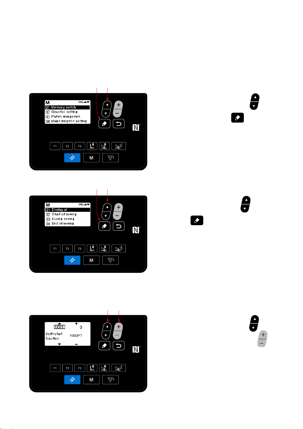
4-5-1. Memory switch data
Memory switch data are the data on sewing machine operation and affect all sewing patterns commonly.
(1) Setting up the memory switch data
Selecting the category of the memory switch data.
①
❺
❼
<Mode screen>
❼
❺
1. Select "01 Memory switch" by pressing
the mode screen. Then, press
the memory switch classication selection screen.
2. Select "01 Display all" by pressing
Then, press
switch setting screen.
* In the case any item other than "01 Display
all" is selected, only the memory switch which
coraresponds to the selected item is displayed on
the memory switch setting screen.
to display the memory
❼
to display
❼
❺
❺
.
on
<Memory switch classication and selection screen>
Setting the memory switch
②
❻❺
<Memory switch setting screen>
1. Select the memory switch by pressing
Then, edit the memory switch by pressing
.
❻
– 45 –
❺
.
Page 49

Conrming the data entered
③
❽
1. Press
to conrm the data and return the
❽
current screen to the memory switch category
selection screen.
Press
again to return the current screen
❽
to the mode screen.
Press
yet again to return the current
❽
screen to the sewing screen.
<Sewing screen>
The memory switch setting screen can also be displayed by pressing the F key to which the
memory switch has been registered on the sewing screen.
In such a case, the memory switch setting screen will be returned to the sewing screen by
pressing
.
❽
– 46 –
Page 50
(2)
List of memory switch data
No Item Setting range
U001 Soft start function 0 to 9 stitches 0: No soft start
1 - 9: Number of stitches to be sewn at the soft-start sewing
speed
U014 Sewing count function 1 to 3 1: Counter counts one when the back part of the pedal is de-
pressed to the second level.
2: Sewing counter switch input
3: Counter counts one every time the absence of material is
detected after the sewing machine has performed sewing
in the state the material is present.
U021 Presser foot goes up
when the pedal is at its
neutral position
U035 Lowest sewing speed by
pedal
U037 Sewing speed for soft-
start function
U038 One-shot sewing speed 100 to 5500 sti/min This memory switch data item is used for setting the sewing
U039 Rotation starting position 10 to 1000 This memory switch data item is used for setting the position
U040 Acceleration starting
position
U041 Presser-foot lifting start-
ing position
U042 Presser-foot lowering
starting position
U043 Cloth-puller lifting and
chain-off thread-cutter
operation starting position
U044 Maximum sewing speed
position
U045 Pedal neutral position
correction value
U047 Presser-foot lifting end
position
U049 Presser-foot lowering
time
U055 Presser-foot lifting after
depressing the back part
of pedal to the 2nd level
0 to 1
150 to 600 sti/min
100 to 5500 sti/min This memory switch data item is used for setting the sewing
speed to be employed while the soft-start function works.
speed to be employed while the one-shot sewing function
works.
from which the sewing machine starts operating by depressing the pedal. (Pedal stroke)
10 to 1000 This memory switch data item is used for setting the acceler-
ation starting position of the pedal with reference to its neutral
position. (Pedal stroke)
–500 to –10 This memory switch data item is used for setting the upper
position of the presser foot by operating the pedal. (Pedal
stroke)
10 to 500 This memory switch data item is used for setting the position
of the pedal at which the presser foot starts coming down with
reference to its neutral position.
–1000 to –100 This memory switch data item is used for setting the position
of the pedal at which the cloth puller goes up (in the case the
pedal position at which the cloth puller goes up is set so that
it goes up after the presser foot with U206), and for setting
the position of the pedal at which the chain-off thread cutter
operates (in the case the operation of chain-off thread cutter
by depressing the back part of pedal is enabled with S043),
with reference to its neutral position. (Pedal stroke)
10 to 15000 This memory switch data item is used for setting the position
of the pedal at which the sewing machine reaches its maximum sewing speed with reference to its neutral position.
(Pedal stroke)
–150 to 150 This memory switch data item is used for setting the neutral
position of the pedal.
–1000 to –100 This memory switch data item is used for setting the position
reached by depressing the back part of pedal to the rst level
(rst-level spring position)
0 to 500 ms This memory switch data item is used for setting the time
during which the presser foot comes down.
0 to 1 This memory switch data item is used for setting the function
for keeping the presser foot at its upper position when the
back part of pedal is depressed to the 2nd level after the completion of sewing.
0: Disabled 1: Enabled
– 47 –
Page 51

No Item Setting range
U068 Presser-foot operation
changeover
U069 First-level presser-foot
lifting height
U070 Second-level press-
er-foot lifting height
U073 Re-try function 0 to 1 0: No re-try 1: Normal re-try
U087 Pedal acceleration char-
acteristic
U090 Upper stop function at
the initial operation
U096 Maximum sewing speed 150 to 5500 sti/min
U120 Main-shaft reference
angle correction
U121 Upper-position starting
angle correction
U122 Lower-position starting
angle correction
U182 Sewing count stop func-
tion
U183 Number of times of
thread trimming for the
sewing counter
U201 Cloth puller lifting height 0.1 to 10.0 mm This memory switch data item is used for setting the height of
U205 Selection of the up-
per-position returning
operation by a depress
on the back part of pedal
U206 Function for lifting the
cloth puller by a depress
on the back part of pedal
0 to 1 This memory switch data item is used for setting the press-
er-foot lifting operation when the back part of pedal is de-
pressed.
0:2-step operation
1: Manual operation according to the stroke determined by
depressing depth of the back part of pedal
0.1 to 10.0 mm This memory switch data item is used for setting the lifting
height of the presser foot when the back part of the pedal is
depressed to the rst level.
0.1 to 10.0 mm This memory switch data item is used for setting the lifting
height of the presser foot when the back part of the pedal is
depressed to the second level.
–10 to 10 -10 - -1: Low-range low acceleration
0: Standard
1 - 10:Low-range high acceleration
0 to 1 0: The sewing machine stops with its needle up after checking
the setting on the operation panel
1:The sewing machine stops with its needle up automatically
–30 to 30 degrees This memory switch data item is used for setting the set value
for correcting the angle (0 degree) of the main shaft reference
signal.
–15 to 15 degrees This memory switch data item is used for setting the set value
for correcting the main shaft angle at which the sewing machine stops with its needle up.
–15 to 15 degrees This memory switch data item is used for setting the set value
for correcting the main shaft angle at which the sewing machine stops with its needle down.
0 to1 0: The sewing machine does not stop according to the sewing
count
1: Start of sewing machine is prohibited after performing
thread trimming when the counter has reached the set
value.
1 to 99 In the case of "U14 = 1", this memory switch data item is
used for setting the number of times of thread trimming (the
number of times that the back part of pedal is depressed to
the 2nd level) when using the sewing counter In the case of
"U14 = 3", this memory switch data item is used for setting
the number of times of sewing of materials to be performed
until the sewing counter value increases one.
the cloth puller to be reached when lifting the cloth puller by
depressing the back part of pedal.
0 to 1 0:Normal returning to the upper position
1: Returning to the upper dead point by reverse rotation
0 to 2 This memory switch data item is used for setting the depress-
ing position of the back-part of pedal to lift the cloth puller.
0: Simultaneously with the presser foot (by depressing the
back part of peal to its 1st level)
1: After the presser foot (by depressing the back part of pedal
to its 2nd level)
2: The cloth puller is not lifted
– 48 –
Page 52

No Item Setting range
U211 Number of stitches for
sewing the material while
the sewing counter is
enabled
U226 Material thickness sensor
value without material
U401 Stitch-length input unit 0 to 2 0:Stitch length (mm)
U402 Automatic lock time 0 to 300 second This memory switch data item is used for setting the period
U403 Automatic OFF of the
back light
U404 Selection of display be-
tween the "part number
and process" and "comment"
U406 Language selection -
0 to 2000 stitches This memory switch data item is used for setting the number
of stitches to be sewn before allowing the sewing counter to
start counting. The sewing counter will not perform counting
unless the sewing machine has performed sewing by the preset number of stitches or more while the presence of material
is detected.
0 to 3000 This memory switch data item is used for setting the material
thickness sensor value when the presser foot is lowered with
the feed dog lowered without material. If this value is not correct, the presser foot pressure cannot be corrected properly.
1:Number of stitches per inch
2:Number of stitches in 3 cm
of time to be passed, in the state the operation panel is not
operated, before the automatic lock function is actuated.
0 to 20 This memory switch data item is used for setting the period
of time to be passed, in the state the operation panel is not
operated, before the back light for the operation panel is auto-
matically turned OFF.
0 : Not turn OFF automatically
1 - 20 : Period of time until the back light is automatically
turned OFF (in minute)
0 to 1 This memory switch data item is used for selecting either the
"part number and process" or the "comment" is displayed on
the sewing screen.
0: Part number and process
1: Comment
Not selected / Japanese / English /
Simplied
Chinese /
U407 Operation sound for the
operation panel
Spanish / German / French / Italian /
Turkish
0 to 1 0:OFF
1:ON
– 49 –
Page 53

4-5-2. Counter function
This function counts sewing in the predetermined unit and gives a visible alarm on the screen when the pre-
set value is reached.
The following counters can be used.
Display on the
sewing screen
Display on the counter
setting screen
Content
Sewing counter (count-up counter)
The current value shown on the counter increases one by one.
When the current value reaches the set value, the "count completed"
screen is displayed.
Sewing counter (count-down counter)
The current value shown on the counter decreases one by one.
When the current value reaches "0" (zero), the "count completed" screen
is displayed.
Pitch time counter
The current value shown on the counter increases one by one.
In addition, the counter value also increases by one every time the preset
pitch time is reached.
The timing at which the current value shown on the sewing counter is as shown below. It can be changed
over according to the setting of "U014 Sewing counter function".
Set value of
U014
1
2 The sewing counter increases by one when an external input is accepted.
3
The sewing counter increases by one when the back part of pedal is depressed to its 2nd level by the
set value of "U183 Number of times of thread trimming for the sewing counter".
The sewing counter increases by one after the sewing machine has repeated the sewing sequence by
"U183 Number of times of sewing of materials" (one sewing sequence = when the absence of material
is detected after the sewing machine performs sewing of material). If the number of stitches sewn on
the material is smaller than "U211 Number of stitches for sewing the material while the sewing counter
is enabled", the relevant sewing sequence will be invalid.
Content
– 50 –
Page 54

(1) How to set the counter
Selecting the counter setting
①
❼
❺
Press
on the mode screen. Select "02
❺
Counter setting". Press
counter setting screen.
<Mode screen>
Setting the type of counter, current value of counter and preset value for counter
②
Type of counter
Current value of
counter
❺
❻
❽
1. The type of counter can be selected by pressing
.
❻
2. Select the target item by pressing
The value of the item you have selected can be
to display the
❼
❺
.
❷
Preset value for counter
<Counter type selection screen>
Type of counter Setting item Setting range
Sewing counter
(Count-up counter) (Count-down counter)
Pitch time counter
Counter unused
changed by pressing
If
is pressed while the current value
❷
or set value of the sewing counter is selected,
the current value or set value can be reset to "0"
(zero).
3. When
is pressed, the screen returns
❽
to the mode screen. When
again, the screen returns to the sewing screen.
Current value 0 to 9999
Set value 0 to 9999
Pitch time
(No setting item)
1.0 to 999.9
(Unit: Second)
❻
.
❽
is pressed
– 51 –
Page 55

(2) Displaying the sewing screen under the counter display mode
Current value on the counter
❻
❹
< Sewing screen (display of the sewing counter) >
1. When
is pressed on the sewing
❹
screen, the screen changes over to the counter
display.
In the case of using the sewing counter
①
2. When the display changes over to the sewing
counter display, the current value is brought in
the "selected state". The current value can be
changed by pressing
When
is pressed, the display returns
❹
❻
.
to the pattern display.
In the case of using the pitch time counter
②
2. When the display changes over to the pitch time
counter display, the set value is brought in the
"selected state".
Pattern display
Sewing counter
Pitch time counter
When
is pressed while the set val-
❹
ue is being selected, the current value can be
changed.
When
is pressed, the value that is in the
❻
"selected state" can be changed.
When
is pressed while the current
❹
value is being selected, the display returns to the
pattern display.
– 52 –
Page 56

(3) How to reset the count-completion state
When the predetermined conditions are satised
during sewing, the count-completion screen is dis-
played.
❷
<Count-completion screen>
The counter is reset by pressing
❷
.
Then, the mode is returned to the sewing mode. In
this mode, the counter starts counting again.
– 53 –
Page 57

4-5-3. How to copy / newly create a pattern
1. Displaying the sewing pattern management screen
Press
display the sewing pattern management screen.
In the case of copying a pattern
①
on the mode screen. Select "03 Sewing pattern management". Then, press
❺
❺ ❻
❼
<Sewing pattern edit screen>
❽
to
❼
2. Displaying the sewing pattern copy / delete
screen
Press
a pattern". Then, press
sewing pattern copy / delete screen.
3. Performing copying
Select the pattern number you want to use as the
copy source by pressing
pattern number you want to use as the copy des-
. Select "01 Copying / deleting
❺
to display the
❼
. Also select the
❺
In the case of deleting a pattern
②
❼
❺
tination by pressing
to perform copying.
❼
When
copied" is displayed. When
again, the screen returns to the sewing pattern
management screen
2. Displaying the sewing pattern copy / delete
screen
Press
a pattern". Then, press
sewing pattern copy / delete screen.
is pressed, the message "Not
❽
. Select "01 Copying / deleting
❺
. Then, press
❻
❼
is pressed
❽
to display the
<Sewing pattern copy / delete screen>
– 54 –
Page 58
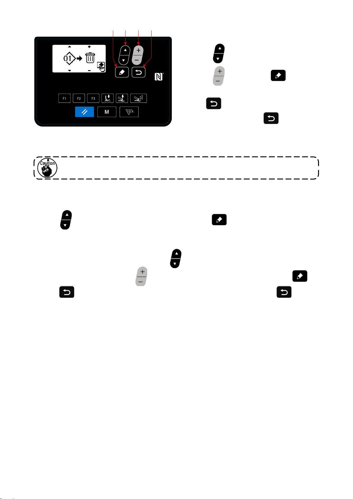
❼
❺ ❻
❽
3. Performing deletion
Select the pattern number you want to delete by
<Sewing pattern copy / delete screen>
If there is only one sewing pattern, the pattern deleting function will be disabled.
In the case of creating a new pattern
③
2. Displaying the new pattern creation screen
Select
. Select "02 Creating a new pattern". Then, press
❺
pressing
pressing
form deletion.
When
deleted" is displayed. When
again, the screen returns to the sewing pattern
management screen.
. Also select the recycle bin by
❺
. Then, press
❻
is pressed, the message "Not
❽
to display the new pattern cre-
❼
❼
is pressed
❽
to per-
ating screen.
3. Performing creation of a new pattern
Select the shape you want to create by pressing
sign to the new pattern by pressing
When
pressed again, the screen returns to the sewing pattern management screen.
is pressed, the message "New pattern is not created" is displayed. When
❽
. Then, the new pattern can be created by pressing
❻
. Then, select a pattern number you want to as-
❺
❽
is
❼
.
– 55 –
Page 59

4-5-4. How to use the warning function
Reminder for maintenance can be generated after the sewing machine has been used for a predetermined
period of time. Five different warning messages can be generated at the maximum depending on the genera-
tion conditions.
(1) Setting the warning function
❺
❼
Selecting the warning number
①
<Warning number selection screen>
❺ ❻
❼
❽
Select "04 Maintenance setting" by pressing
on the mode screen. Then, display the warn-
❺
ing number selection screen by pressing
.
❼
After the warning number selection screen is dis-
played, the warning number can be selected by
pressing
Warning is canceled
②
❺
.
The warning counter details setting screen is
displayed by pressing
on the warning
❼
number selection screen.
After the warning number selection screen is dis-
played, select the target item by pressing
❺
.
<Warning counter details setting screen>
Setting items Setting range
Allowed (ON)・Prohibited (OFF)
Clearing of the counter by operator
Comment 0 - 16 characters
Object of counter
Numerator for counter 1 to 99999
Dominator for counter 1 to 99999
Number of stitches (in incre-
ment of 1000 stitches)
Set the details of the target item by pressing
. The items described below can be set.
❻
When
is pressed, the screen returns to
❽
the warning number selection screen.
Operating time
(unit: Hour)
Energizing time
(unit: Hour)
– 56 –
Page 60
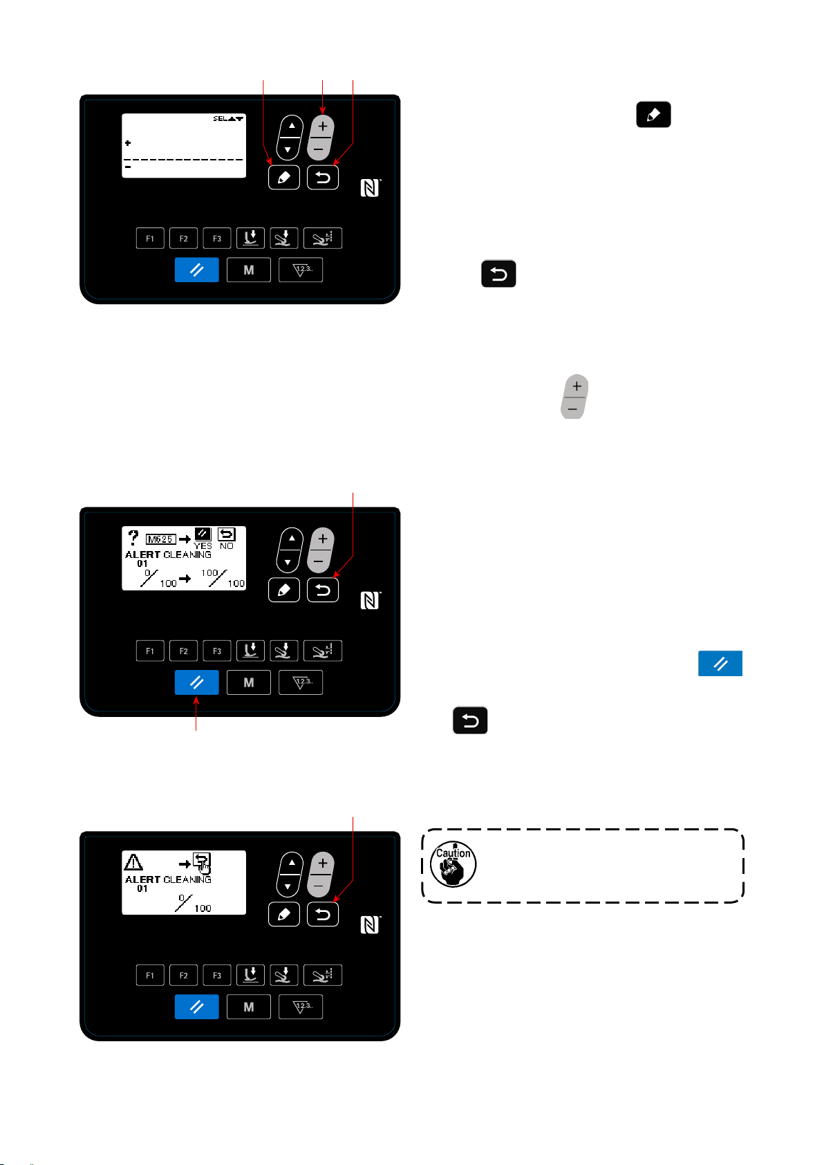
❼
❻
❽
Adding a comment to the warning
③
Select the comment on the warning counter de-
<Warning counter comment input screen>
(2) Cancelling the warning function
❽
tails setting screen. Then press
❼
to dis-
play the warning counter comment input screen.
The comment you input will be displayed on the
screen when the relevant warning is generated.
It is therefore recommended to input a comment
that represents details of the maintenance (for
example, CLEANING) for convenience.
When
is pressed, the screen returns to
❽
the warning counter details setting screen.
Enabling the warning function
④
Select "ON" on the warning number selection
screen by pressing
to enable the warning
❻
function.
A warning is generated
①
When the warning counter value reaches the set
value at the completion of sewing, the warning
screen is displayed.
❷
<Warning screen (in the case clearing of the counter
by operator is allowed)>
❽
Closing the warning screen
②
The warning counter is reset and the screen is re-
turned to the previous screen by pressing
on the warning screen.
❷
If
is pressed, the screen will return to
❽
the previous screen without resetting the warning
counter. In this case, the warning screen will be
displayed every time the sewing machine com-
pletes sewing until the warning counter is reset.
Operation of the reset key (as described
in ②.) is enabled in the case clearing of
the counter by operator is allowed.
<Warning screen (in the case clearing of the counter
by operator is prohibited)>
– 57 –
Page 61

(3) Resetting the warning when no warning is generated
In order to reset the warning in the case that no warning is generated, return the numerator of the counter to
the same value with the dominator of the counter on the warning counter details setting screen, or carry out
the following steps of procedure.
❺
❼
Selecting the warning number
①
<Warning number selection screen>
❼
❽
Select "04 Maintenance setting" by pressing
on the mode screen. Then, display the warn-
❺
ing number selection screen by pressing
.
❼
After the warning number selection screen is dis-
played, the warning number can be selected by
pressing
Setting details of the warning
②
When
ber selection screen, the warning counter clearing
screen is displayed.
After the warning counter clearing screen is dis-
played, reset the warning counter and return the
.
❺
is pressed on the warning num-
❼
❷
<Warning counter clearing screen>
screen to the previous screen by pressing
.
❷
If
the previous screen without resetting the warning
counter.
is pressed, the screen will return to
❽
– 58 –
Page 62
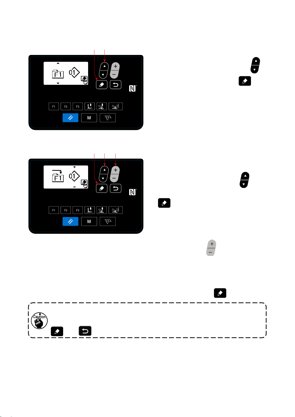
4-5-5. How to use the F key
(1) How to use the F key
❼
❺
Displaying the F key number selection screen
①
<F key number selection screen>
❺ ❻
❼
Select "05 F Key registration" by pressing
on the mode screen. Then, press
❺
display the F key number selection screen.
Displaying the F key registration data selec-
②
tion screen
Select the F key number by pressing
the F key number selection screen. Then, press
to display the F key registration data
❼
❼
❺
to
on
selection screen.
Carrying out registration
③
Select the data / function you want to register to
<F key registration data selection screen>
the F key by pressing
on the F key reg-
❻
istration data selection screen. Then, registration
is carried out (the selected data / function will be
returned to the unregistered state if the recycle
bin is selected) and the screen returns to the pre-
vious screen by pressing
The F key registration data selection screen can also be displayed by keeping the F key held
pressed for one second on the sewing screen.
In this case, the F key registration data selection screen will return to the sewing screen if the
(or
❼
) is pressed.
❽
❼
.
– 59 –
Page 63
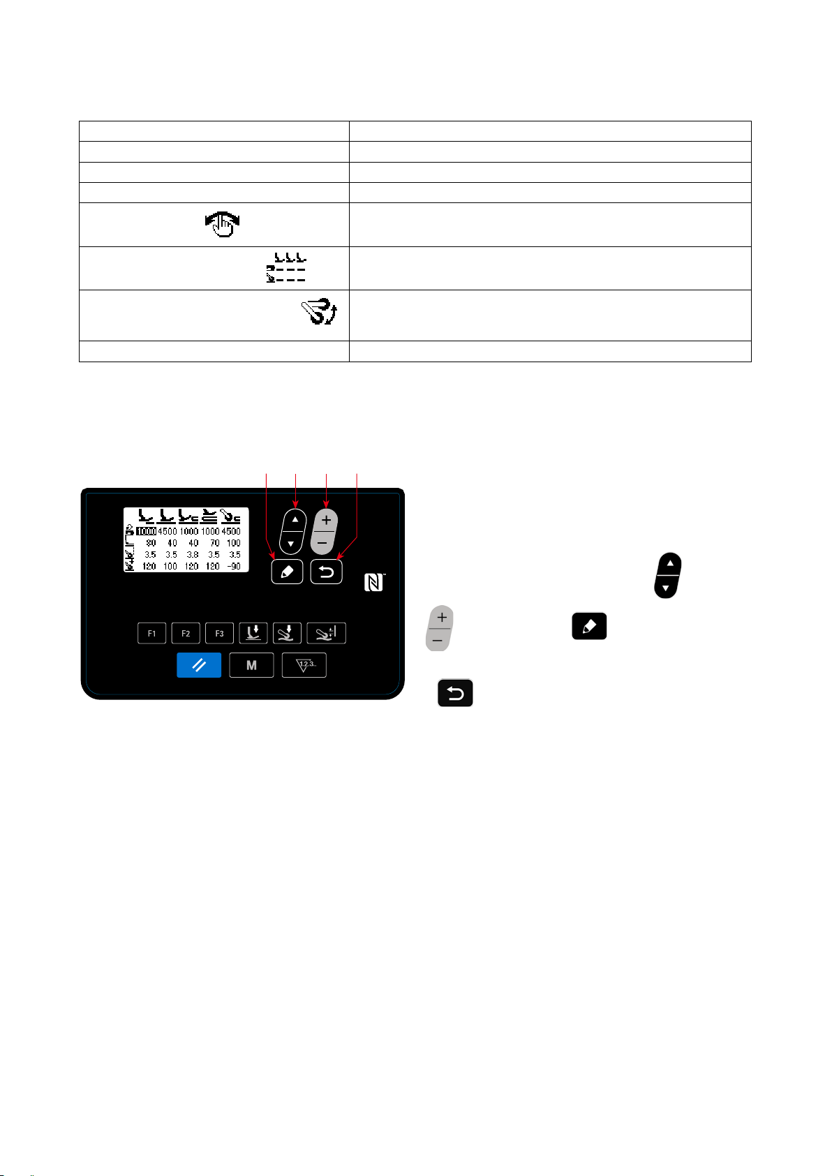
(2) Data / function that can be registered to the F key
The following data / function can be registered to the F key.
The F key can be operated on the sewing screen, sewing data edit screen and the memory switch setting screen.
Data / function Function
Pattern A pattern is selected.
Sewing data The sewing data edit screen is displayed.
Memory switch (Level 1) The memory switch setting screen is displayed.
One-touch function *
Sewing data list display function
Cloth puller up / down travel function *
Recycle bin (cannot be used)
*: It is the function that can only be on the sewing screen.
❺ ❻
❼
Step of the step sewing pattern proceeds to the next one.
The list of sewing data is displayed.
The cloth puller is moved upward (or downward). This function is
useful for lifting the cloth puller in the case you do not want to use the
cloth puller temporarily.
❽
When the F key to which the "sewing data list dis-
play function" is registered is pressed, the sewing
data list display screen appears.
Select the sewing data by pressing "
)". Then, press
❻
❺
to display the sew-
❼
(or
<Sewing data list display screen>
ing data edit screen.
If
is pressed, the screen will return to the
❽
sewing screen.
– 60 –
Page 64
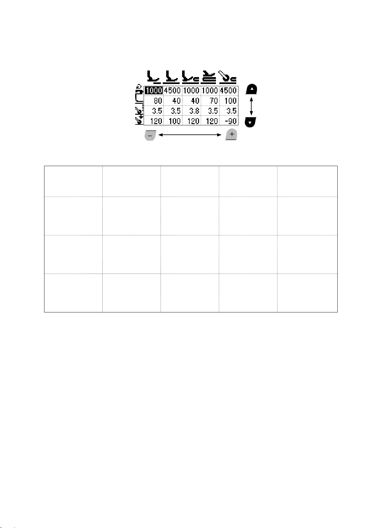
The positions at which the respective sewing data items are displayed on the sewing data list display screen
are as follows.
A B C D E
1
2
3
4
(Direction in which the
sewing data is selected)
A B C D E
S031
Sewing speed for
1
starting sewing of the
top end of material
S032
Presser foot pres-
2
sure for starting sewing of the top end of
material
S072
Cloth pulling amount
3
when detecting no
material
S073
Cloth puller pressure
4
when detecting no
material
S004
Limit of sewing speed
S005
Presser foot pressure
S006
Cloth pulling amount
S007
Cloth puller pressure
S012
Multi-layered section
sewing speed
S005
Presser foot pressure
S015
Cloth pulling amount
when the presser foot runs on the
multi-layered section
S016
Cloth puller pressure
when the presser foot
runs on the multi-layered section
S012
Multi-layered section
sewing speed
S018
Presser foot pressure for sewing the
multi-layered section
S019
Cloth pulling amount
for sewing the
multi-layered section
S020
Cloth puller pressure for sewing the
multi-layered section
S004
Limit of sewing speed
S078
Presser foot pressure
when the cloth puller
runs on the multi-layered section
S070
Cloth pulling amount
when the cloth puller
runs on the multi-layered section
S071
Cloth puller pressure
when the cloth puller
runs on the multi-layered section
– 61 –
Page 65
4-5-6. Checking the version information
B
<Version information screen>
A
❼
❺
❽
Select "06 Version display" by pressing ❺
①
on the mode screen. Then, press ❼ to
display the version information screen.
A represents the version of the panel software. B
represents the version of the main-body software.
Press
②
to the
sewing screen
Press
screen to the
4-5-7. Adjusting the contrast of the LCD of the operation panel
❺
❻
❼
❽
Selecting the contrast setting function
①
again to return the current screen
❽
.
yet again to return the current
❽
mode screen
.
<Contrast setting screen>
Select "07 Contrast setting" by pressing
on the mode screen. Then, press
display the contrast setting screen.
Setting the contrast
②
Set the contrast by pressing
Setting range : 0 (bright) to 4 (dark)
If the
be turned white to allow you to check for uneven-
ness of display on the screen.
(When the
returns to the previous display.)
Press
③
current screen to the
is pressed, the entire screen will
❺
is pressed again, the screen
❺
to conrm the data and
❽
sewing screen
❻
.
❼
.
return the
to
❺
Press
– 62 –
screen to the
yet again to return the current
❽
mode screen
.
Page 66

4-5-8. Communication function
Data can be input/output by means of a USB thumb drive.
(1) How to use the communication function
A
❼
❺
❻
Selecting the communication function
①
<Communication data/communication direction selection
screen>
❻
C
D
❼
❺
1. Select "08 Communication" by pressing
on the mode screen. Then, press
❼
to dis-
play the communication data / direction selection
screen.
Select the communication direction.
②
1. Select the communication data A by pressing
.
❻
: Data stored on the operation panel is writ-
ten to the USB thumb drive.
: Data stored on the USB thumb drive is
written to the operation panel.
2. Press
to display the communication
❼
data number selection screen.
❺
<Communication data number selection screen>
Selecting the target data number
③
1. Select the source data No. C by pressing
2. Select the destination data number D by pressing
3. Press
to display the during-communication screen and write the data.
❼
❺
.
.
❻
After the completion of writing, the current screen returns to the communication data number selection
screen.
* If the "POWER OFF" screen prompt is displayed after the completion of writing, turn the power OFF.
(2) List of communication data formats
Data name Pictograph Extension Description of data
Sewing data SC00XXX.EPD
(XXX:001 to 999)
MS-1261A-specic sewing data format for sewing
shape and stitch length created on the sewing machine
– 63 –
Page 67
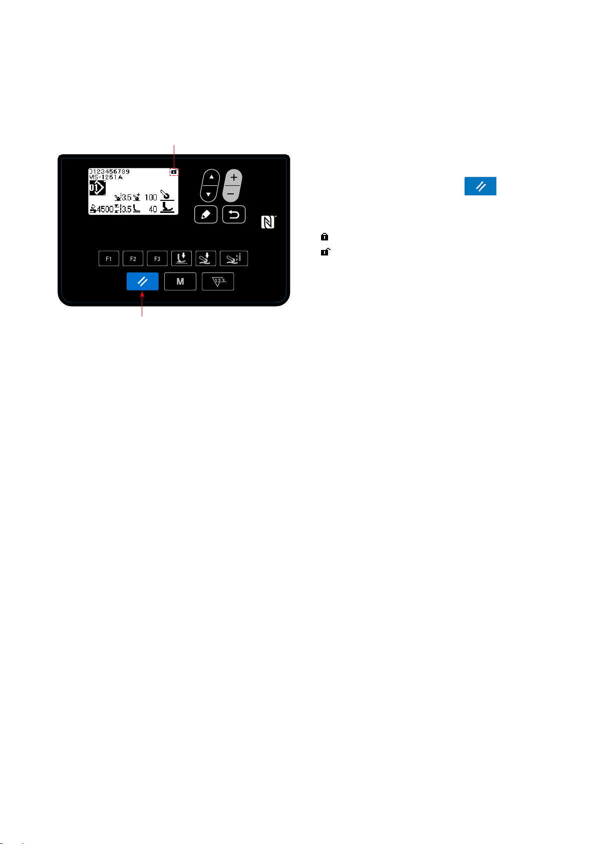
4-6. Information
4-6-1. Simple lock
Once the simple lock is enabled, key operation can be disabled if no operation is carried out on the sewing
screen for a certain period of time, thereby preventing maloperation.
A
The status of the simple lock can be changed over
between enable/disable by keeping
pressed for one second on the sewing screen.
Pictograph display A will be as shown below:
: Simple lock is enabled
: Simple lock is disabled
❷
<Sewing screen>
* The time to be elapsed until the simple lock is enabled can be set with the memory switch U402.
Refer to
* Even if the simple lock is disabled once, the status of the simple lock will return to "enable" if no operation
is carried out in a certain period of time. In the case you do not want to use the simple lock function, set
U402 to 0 (zero).
"4-5-1. Memory switch data" p. 45
for details.
❷
held
– 64 –
Page 68

4-7. List of errors
Error code Description of error Cause Item to be checked
E000 Execution of data initial-
ization (This is not an
error.)
E007
E011 Media is not inserted • In the case no media is inserted. • Turn the power OFF and check for a media.
E012 Read error • In the case data stored on the
E013 Write error • In the case data cannot be writ-
E014 Write protect • In the case the media is placed
E015 Format error • In the case formatting of the
E016 External media over-ca-
E019 File size over • In the case of attempting to read
E022 File undetected • In the case of attempting to read
E031 Air pressure drop • In the case the air pressure has
E032 File compatibility error • In the case the le is not com-
E071 Motor output connector
E079 Overload operation error • An excessive load is applied to
E081 Cloth puller motor devia-
E204 USB thumb drive insertion • This error message is displayed
Motor overload
pacity
disconnection
tion error
• In the case the control box is
changed.
• In the case the initialization
operation is executed.
• In the case the machine head is
locked.
• In the case of sewing extra-heavy weight material that
exceeds the guaranteed material thickness.
• In the case the motor fails to
rotate.
• In the case of the motor or driver
failure.
media cannot be read.
ten on the media.
in the write-prohibition state.
media cannot be carried out.
• In the case the capacity of media
is not enough.
the le that exceeds the maximum possible size from the USB
thumb drive to the operation
panel.
the le that is not stored in the
USB thumb drive to the operation panel.
dropped.
patible.
• The motor connector has slipped
off.
the main shaft motor.
• Load applied to the cloth puller
motor is too large for the motor
to operate.
in the case the sewing machine
is started while a USB thumb
drive remains in the sewing
machine.
Not a failure
• Check whether the pulley is entangled with
thread.
• Check whether the motor output connector
has loosened.
• Check whether the motor can be turned
smoothly by hand.
• Turn the power OFF and check for a media.
• Turn the power OFF and check for a media.
• Turn the power OFF and check for a media.
• Turn the power OFF and check for a media.
• Turn the power OFF and check for a media.
• Turn the power OFF and check the USB
thumb drive.
• Turn the power OFF and check for a media.
• Check for looseness and slip-off of the motor
output connector.
• Check whether the cloth puller motor runs
smoothly.
• Remove the USB thumb drive.
– 65 –
Page 69

Error code Description of error Cause Item to be checked
E231 "With no magnetic-proper-
ty adjustment data" error
E302 Tilt detection switch • In the case the Tilt detection
E303 Meniscus sensor error • In the case the meniscus sensor
E402 Deletion disabled error
E407 Wrong password • In the case the password you
E411 Step sewing pattern regis-
tration disabled error
E414 Already existing le • In the case of attempting to
E415 File name contains an
unusable character(s)
E416 Enter a le name • In the case of attempting to
E489 Internal error
• In the case the magnetic property of the motor is not adjusted
after the motor replacement.
• In the case the motor magnetic
property adjustment data cannot
be read.
switch is turned ON when the
power to the sewing machine
remains ON.
signal cannot be detected.
have entered is not correct.
• In the case of attempting to
create 11 or more step sewing
patterns.
creating the keylock resetting
le which has the name that is
same as the existing le in the
USB thumb drive.
• In the case of attempting to
assign a name that contains
an unusable character(s) when
creating a le.
conrm the created le without
assigning a name to it.
• Adjust the magnetic property of the motor.
(Refer to the Engineer's Manual for details.)
• Check the motor-encoder connector.
• Check whether the machine head is tilted
before turning OFF the power switch (The
sewing machine operation is prohibited for
the sake of safety.).
• Check for a break in the motor encoder
connector.
E499 Simplied program fault
E703 Sewing machine model
error
E704 Data failure (system-ver-
sion mismatch)
E706 Operation panel fault
E731
E733
Motor hole sensor fault
Reverse rotation of motor
E750 Sewing machine stops • In the case the safety switch for
• In the case the model name of
sewing machine does not match
the model name registered on
the operation panel.
• In the case the system version
does not match the machine
head setting.
• In the case the motor signal is
not input properly.
• This error occurs in the case the
motor rotates at the speed of
500 sti/min or more, in the direction opposite to the indicated
direction of rotation.
the optional input is pressed.
• Re-write the system version to the applicable
one.
• Check whether the motor signal connector
has loosened or slipped off.
• Check whether the motor signal cord has
broken by being caught under the machine
head.
• Check whether the insertion direction of the
motor encoder connector is correct.
• Check whether the main shaft motor encoder
wire connection is correct.
• Check whether the main shaft motor wire
connection for power is correct.
– 66 –
Page 70

Error code Description of error Cause Item to be checked
E811 Over-voltage • In the case a voltage that is
equal to or more than the guaranteed voltage is input.
• In the case a voltage of 400 V is
applied to the box of "CE: 230
V".
E813
E815 Regenerative resistor is
Low voltage
not connected
• In the case a voltage that is
equal to or less than the guaranteed voltage is input.
• In the case the internal circuit
has broken due to the application of over-voltage.
• In the case the regenerative
resistor is not connected.
• Check whether the supply voltage of "rated
supply voltage ±10 % or more" is applied.
In the above-described cases, the power PCB
has broken.
• Check whether the supply voltage of "rated
supply voltage -10 % or less" is applied.
In the above-described cases, the power PCB
has broken.
• Check whether the regenerative resister
is connected to the regenerative resistor
connector (CN11).
E900 Protection of the main
shaft motor against IPM
overcurrent
E902 Main shaft overcurrent
• Main shaft motor maloperation.
E903 85-V power supply fault
• In the case the 85-V voltage
is not properly output.
E904 24-V power supply fault
• In the case the 24-V voltage
is not properly output.
E910 The presser motor origin
retrieval error
• In the case the presser motor
has failed to return to its origin.
E912 Main shaft motor speed
detection error
• In the case the main shaft
motor runs at a speed that
exceeds the assumed speed.
E915 Failure of communication
with operation panel
E918 Main PCB temperature
error
E922 Main shaft control failure • In the case the main shaft fails
E924 Motor driver fault • In the case the motor driver has
E946 Machine-head EEPROM
write error
E955 Current sensor fault • Main shaft motor failure
E961 Cloth puller presser motor
deviation error
E962 Presser motor deviation
error
E963 IPM temperature error • The temperature of the CTL
E967 Main shaft motor tempera-
ture fault
• In the case the operation panel
connector is not inserted properly.
• The temperature of the CTL
PCB is excessively high.
to operate as assumed.
broken.
• The machine head PCB is not
properly connected.
• Current sensor failure.
• Load applied to the cloth puller
presser motor is too large for the
motor to operate.
• In the case the presser fails to
operate because of an excessive load.
PCB is excessively high.
• Load applied to the main shaft
motor is excessively large.
• Check whether the motor is faulty
• Check the F2 fuse.
• Check whether the presser setting is
correct (memory switch No. 23).
• Check whether the presser motor origin
has been correctly adjusted.
• Check whether connection encoder wire
of the main shaft motor is correct.
• Check whether connection of the main
shaft motor wire is correct.
• Check whether CN64 of the CTL PCB or
CN200 of the panel is connected properly
or whether the cable has broken.
• Check the connector CN32 for looseness of
slip-off.
• Check whether the main shaft motor has
short-circuited.
• Check whether the cloth puller presser motor
runs smoothly.
• Check whether the presser motor runs
smoothly.
– 67 –
Page 71
Error code Description of error Cause Item to be checked
E971 Protection of the cloth
puller motor against IPM
overcurrent
E972 Cloth puller presser motor
overload error
E973 Protection of the cloth
puller motor against IPM
overcurrent
E974 Cloth puller motor over-
load error
E975 Presser foot motor over-
current error
E976 Presser foot motor over-
load
E977 CPU fault • In the case the program is faulty.
• Cloth puller motor maloperation.
• Load applied to the cloth puller
presser motor is excessively
large.
• Cloth puller motor maloperation.
• Load applied to the cloth puller
motor is excessively large.
• Presser motor maloperation.
• In the case the presser motor is
applied with an excessive load.
• Check whether the cloth puller presser motor
runs smoothly.
• Check whether the feed driving motor runs
smoothly.
• Check whether the presser motor runs
smoothly.
E978 Network communication
fault
E985 Cloth puller presser motor
origin retrieval error
E999 Main software rewriting • In the case the software has
• Data received from the network
has broken.
• In the case the cloth puller
presser motor has failed to
travel to its origin.
been rewritten.
• Check whether the cloth puller presser motor
runs smoothly.
• This is not an error.
– 68 –
Page 72

4-8. External interface
4-8-1. USB
It is possible to copy the sewing data using the commercially-available USB thumb drive.
Refer to
thumb drive.
①
"4-5-8. Communication function" p. 63
Position of the USB connector
❶
for details of how to copy the sewing data on a USB
[USB thumb drive insertion position]
❷
The USB connector is provided on top ❶ of the
operation panel.
To use a USB thumb drive, remove connector
cover ❷ and insert the USB thumb drive into the
USB connector.
* In the case a USB thumb drive is not used,
the USB connector should be protected with
connector cover ❷ without exceptions.
If dust or the like enters the USB connector, a
failure can be caused.
Precautions to be taken when handling USB devices
②
• Do not connect to the USB connection terminal other than the USB memory.
It may cause failure.
• Do not leave the USB device or USB cable connected to the USB port while the sewing machine is in
operation. The machine vibration can damage the port section resulting in loss of data stored on the
USB device or breakage of the USB device or sewing machine.
• Do not insert/remove a USB device during reading a program or sewing data.
It may cause data breakage or malfunction.
• When the storage space of a USB device is partitioned, only one partition is accessible.
• Never forcefully insert a USB thumb drive into the USB connector while carefully checking the orientation of the USB thumb drive. Forceful insertion of the USB thumb drive can cause failure.
• JUKI does not compensate for loss of data stored on the USB device caused by using it with this sewing
machine.
• In principle, connect only one USB thumb drive to the operation panel. When two or more devices/media
are connected/inserted, the machine will only recognize one of them. Refer to the USB specications.
• Do not turn the power OFF while the data on the USB ash drive is being accessed.
USB specications
③
• Conform to USB 1.1 standard
• Applicable devices *
• Format supported ������ FAT 12, FAT 16, FAT 32
• Applicable medium size �� 4.1MB ~ (2TB)
• Consumption current ���� The rated consumption current of the applicable USB devices is 500 mA at
*1: JUKI does not guarantee operation of all applicable devices. Some device may not operate due to a
compatibility problem.
1 ����
USB memory
the maximum.
– 69 –
Page 73
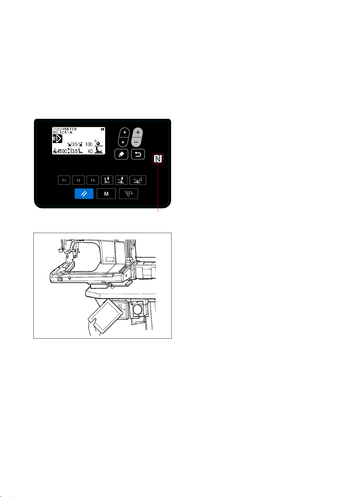
4-8-2. NFC
The operation panel supports NFC (Near Field Communication).
Sewing data, maintenance information or the like can be viewed, edited, copied, etc., on an Android terminal
(such as tablet and smartphone) on which JUKI application for Android [JUKI Smart App] has been installed,
by means of the NFC communication function.
Refer to the Instruction Manual for JUKI Smart App for details of JUKI application for Android [JUKI Smart
App].
Position of the NFC antenna
①
Position of the NFC antenna
①
<Fig.1>
In the case of carrying out the NFC communica-
tion between the sewing machine and a tablet
or smartphone, bring the antenna of the tablet or
smartphone near to NFC mark ❶ as shown in
Fig. 2.
❶❶1❶
❶
* If the NFC communication has failed, error mes-
sage will be displayed on the tablet/smartphone
screen.
When the error message is displayed on the
screen, carry out the NFC communication again.
<Fig.2>
Precautions to be taken when handling NFC
②
• The position of the NFC antenna varies according to the tablet/smartphone used.
Be sure to read the instruction manual of your device before using the NFC communication function.
• To use the NFC communication function, place the NFC communication function setting in "Enable"
while referring to the instruction manual for your tablet/smartphone.
– 70 –
Page 74
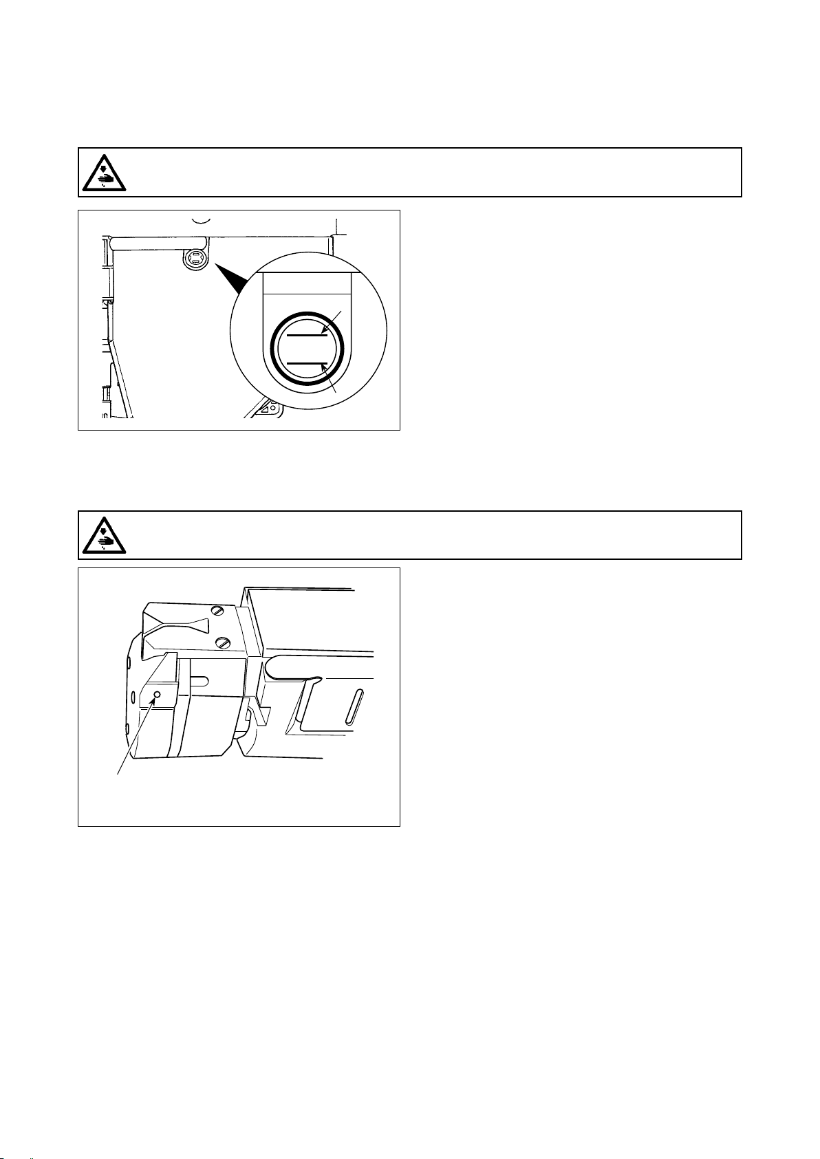
H
L
5. CARE
Perform the maintenance below every day for longer use of your machine.
5-1. Oil quantity in the oil tank
WARNING :
Turn OFF the power before starting the work so as to prevent accidents caused by abrupt start of the
sewing machine.
Check to make sure that the oil surface remains
between two indicator lines (upper marker line A
and lower marker line B) on the oil-quantity gauge
window. Refer to "2-3. Oiling and draining of oil"
A
B
p. 4 for details.
5-2. Lubricating the chain off thread cutter
WARNING :
Turn OFF the power before starting the work so as to prevent accidents caused by abrupt start of the
sewing machine.
OIL
C
Apply several drops of oil to the portion C once or
more every week.
– 71 –
Page 75

5-3. Changing the cloth puller belt
WARNING :
Turn OFF the power before starting the work so as to prevent accidents caused by abrupt start of the
sewing machine.
1) Raise the cloth puller.
❹
❶
❶
❷
❶
2) Loosen cloth puller belt cover setscrews ❶. Then,
detach cloth puller belt cover ❷.
3) Pull up tension pulley ❸ in the direction of the
arrow to loosen cloth puller belt ❹ until it can be
detached.
4) Attach new cloth puller belt. Then, attach cloth
puller belt cover ❷.
❸
With respect to the time for changing the cloth puller belt, change it with a new one when the cloth
belt puller slips or you observe malfunction (cracks, abrasion, etc.) in appearance.
– 72 –
Page 76

5-4. Cleaning
WARNING :
Turn OFF the power before starting the work so as to prevent accidents caused by abrupt start of the
sewing machine.
❶
❶
Open looper cover ❶. Blow out dust gathering on /
in the feed dog, etc. with an air gun provided for the
sewing machine while covering the other parts with
a piece of cloth, etc.
If dust has accumulated in the sewing
machine head, sewing machine failures
such as breakage of feed dog or looper
can occur.
Blow off dust accumulated on the cutter, etc. with
an air gun provided for your sewing machine while
covering the air gun with a piece of cloth.
If dust accumulates on the cutter, the
cutter failure such as breakage can be
caused.
❷
Blow away the dust accumulated in near side of
the looper thread cam through the hole in the cover
stopper screw section.
When bag ❷ is full of thread waste, empty the bag.
– 73 –
Page 77

5-5. Replacing the fuse
DANGER :
1. To avoid electrical shock hazards, turn OFF the power and open the control box cover after about
ve minutes have passed.
2. Open the control box cover after turning OFF the power without fail. Then, replace with a new fuse
with the specied capacity.
❶
The machine uses the following one fuse :
MAIN PWB
❶ For 85V power supply protection
5A (time-lag fuse)
– 74 –
 Loading...