

JUKI MP-200N Series Engineer's Manual
R
ENGINEER’S MANUAL
29337300
No.E332-01
Special 2-needle Pin-point
Saddle Stitch Machine
MP-200N Series

PREFACE
This Engineer’s Manual is written for the technical personnel who are responsible for the service and maintenance of
the machine.
The Instruction Manual for these machines intended for the maintenance personnel and operators at an apparel
factory contains operating instructions in detail. And this manual describes “Standard Adjustment”, “Adjustment
Procedures”, “Results of Improper Adjustment”, and other important information which are not covered by the Instruction
Manual.
It is advisable to use the relevant Instruction Manual and Parts List together with this Engineer’s Manual when carrying
out the maintenance of these machines.
In addition, for the motor for the sewing machine with thread trimmer, refer to the separate Instruction Manual or
Engineer’s Manual for the motor. And for the control panel, refer to the Instruction Manual for the control panel.
This manual gives the “Standard Adjustment” on the former page under which the most basic adjustment value is
described, and on the latter page “Results of Improper Adjustment” under which stitching errors and troubles arising
from mechanical failures are described together with the “Adjustment Procedures”.

CONTENTS
1. SPECIFICATIONS ............................................................................................. 1
2. STITCHES OF PIN-POINT SADDLE STITCHING ............................................ 2
3. CAUTIONS ON SEWING .................................................................................. 2
4. CORNER STITCHING .......................................................................................2
5. STANDARD ADJUSTMENT ............................................................................. 3
(1) Adjusting the position of the feed dog.......................................................................... 3
1) Adjusting the longitudinal position ............................................................................................................ 3
2) Adjusting the lateral position..................................................................................................................... 3
3) Adjusting the inclination ............................................................................................................................ 3
(2) Adjusting the height of the feed dog ............................................................................. 5
(3) Adjusting the vertical movement of the feed................................................................ 5
(4) Feed cam timing .............................................................................................................. 7
(5) Height of the needle bar.................................................................................................. 9
(6) Looper crank timing ........................................................................................................ 9
(7) Position of the loop guide............................................................................................. 11
(8) Adjusting the needle and the looper............................................................................ 11
(9) Adjusting the stroke of the spreader........................................................................... 13
(10) Adjusting the needle and the spreader ..................................................................... 13
(11) Timing of relationship among the needle, looper and spreader............................. 15
(12) Adjusting the spreader timing.................................................................................... 15
(13) Adjusting the backlash of the spreader gear............................................................ 17
(14) Adjuting the height of the spreader........................................................................... 17
(15) Position of the looper link eccentric pin ................................................................... 19
(16) Adjusting the thread take-up thread guide ............................................................... 19
(17) Adjustment to adapt to the overlapped section of the heavy-weight materials.... 21
(18) Replacing the needle bar crank (optional component)............................................ 23
6. MOTOR PULLEY AND V BELT ...................................................................... 25
7. CONSUMABLE PARTS AND SELECTIVE PARTS .......................................25
8. TROUBLES AND CORRECTIVE MEASURES............................................... 27
9. DRAWING OF THE TABLE ............................................................................ 30
−1 −
1. SPECIFICATIONS
(1) MP-200N SERIES
No.
1
2
3
4
5
6
7
8
9
10
11
12
13
14
15
16
17
18
19
20
21
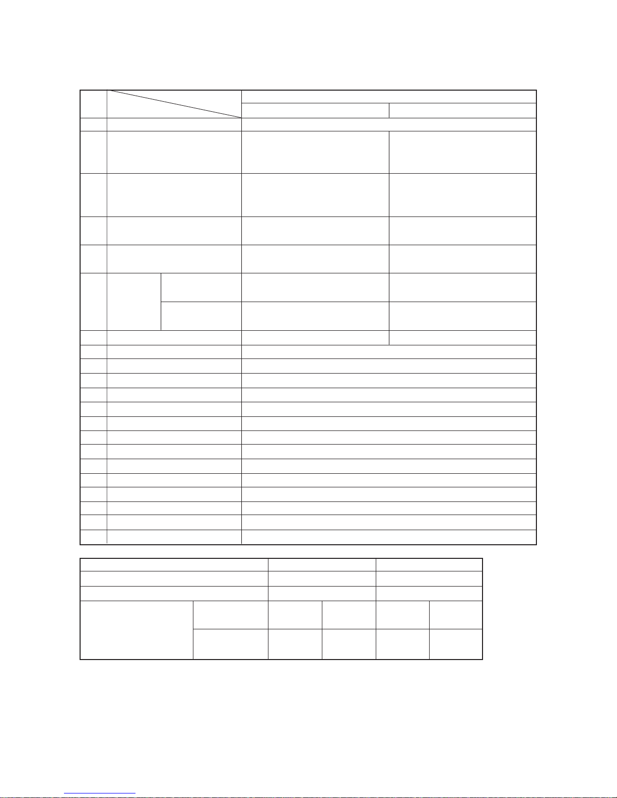
Model name
Item
Machine type
Application
Sewing speed
(normal sewing speed)
Stitch length
Needle gauge
Needle
Applicable thread count
Lift of presser foot
Stitch adjusting method
Thread take-up lever
Needle bar stroke
Feed mechanism
Main shaft/hook driving shaft drive
Lubrication
Lubricating oil
Bed size
Space of sewing area
Handwheel size
Transmission belt
Motor used
Table
Specifications
Pin-point saddle stitch
Hand lifter : 5.5 mm Knee lifter : 12 mm
Dial method
Link type
23.8 mm
Rectangular feeding
Bevel gear
Manual
New Defrix Oil No.2 (Equivalent to ISO VG32)
467 mm X 178 mm
265 mm from needle entry point
V belt effective diameter : ø67.4 mm
M type V belt
4P 400W motor (Motor with needle positioner can be used.)
Table for lockstitch machine can be used.
MP-200NS
For pin-point stitching of gents’ suits,
etc. (Light-weight to medium-weight
materials)
Max. 2,000 rpm
(Normal 1,500 rpm)
3.5 to 10 mm Reverse feed stitching
impossible
1.6 mm (standard), 2.0 mm (accessory)
(Optional : 1.2 mm, 2.5 mm)
SHEMETZ 29-C-150 Nm80 to
Nm140 (Standard Nm90)
SCHMETZ 29-C-151 Nm80 to
Nm140 (Standard (Nm100)
Tetron and spun threads/#60 to #30
MP-200NL
For pin-point stitching for ladies’ suits,
etc. (Light-weight to medium-weight
materials)
Max. 1,500 rpm up to feed pitch 8 mm
Max. 1,200 rpm when exceeding feed
pitch 8 mm
10 mm (When needle gauge is 5 mm)
Reverse feed stitching impossible
5.0 mm (standard)
(Optional : 3.0 mm, 4.0 mm)
ORGAN CP X 1J #18U to #22U
(Standard #22U)
ORGAN CP X 12J #19 to #23
(Standard #23)
Tetron and spun threads/#30 to #8
Sewing needle
Hook needle
* The distance from the top surface of the throat plate is when the needle bar is in its upper dead point.
Model
Needle gauge (mm)
Difference in level between needles (mm)
Distance from top surface of
throat plate (mm) *
Sewing needle
Hook needle
MP-200NS
1.6
1.3
MP-200NL
5
1.3
7
5.7
29C150
29C151
7
5.7
CPx1J
CPx12J
−2 −
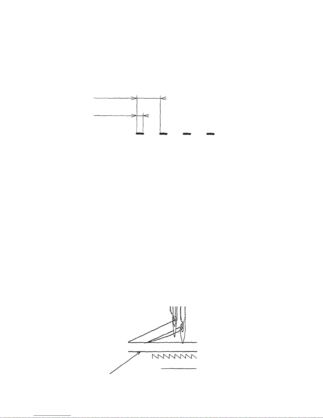
2. STITCHES OF PIN-POINT SADDLE STITCHING
Pin-point saddle stitching is a stitching method that performs handsewn feeling with a single piece of
thread. Imitation hand-stitch decorative stitching at low cost and with high productivity can be performed in
the process where stitches of the wrong side such as decorative stitches of lapel on gents’ coat or the like
do not appear. For the pin-point saddle stitching, the stitches are formed by means of the concerted action
of sewing needle, hook needle, spreader and looper. Distance between two needles becomes the stitch
width. Distance of stitch plus the portion where stitch does not appear becomes feed pitch.
Relation between stitch (center-to-center of needles) of product and pitch is as described below.
Stitch like a loop is formed since this machine is a single thread chainstitch machine, and the loop is formed
on the sewn product. Accordingly, sewing is performed from the wrong side of product when sewing.
3. CAUTIONS ON SEWING
Conditions when performing curve stitching are deteriorated since sewing needle and hook needle pierce
materials simultaneously. When sewing needle does not pierce the loop that the hook needle has hooked,
stitch skipping may occur, or needle may be bent by materials and come in contact with spreader or looper.
As a result, needle breakage, or damage of spreader or looper may occur.
The more the clearance between needle and needle widens, the more this tendency becomes apparent.
In addition, be sure not to turn the material with the needle pierced. The needle is bent by the material and
comes in contact with spreader or looper. As a result, needle breakage, damage of spreader or looper may
occur. In addition, stitches are not formed, and stithing failures such as stitch skipping, thread breakage,
fabric yarn breakage, etc. will occur.
4. CORNER STITCHING
Corner stitching making hook needle the center can be performed if the top end of hook needle slightly
pierces the material while the hook needle hooks loop and sewing needle is in the loop when needle bar
comes down.
Timing is very delicate and high technique is required. Perform carefully when you want to execute this
stitching. In addition, the motor with needle positioner is recommended.
Center-to-center
of needles (stitch)
Material
Feed pitch
−3 −
1) Adjusting the longitudinal position
2) Adjusting the lateral position
3) Adjusting the inclination
5. STANDARD ADJUSTMENT
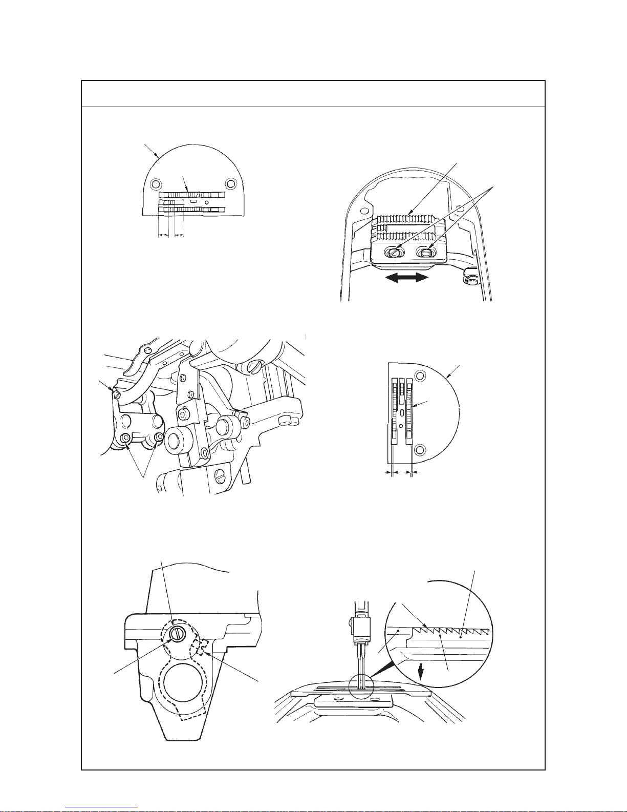
(1) Adjusting the position of the feed dog
Standard Adjustment
C = D (equal)
Hole in machine bed
1
2
6
2
A = B (equal)
AB
Adjust feed dog 2 so that it is longitudinally
equal in terms of the groove for the feed dog
of throat plate 6.
2
3
6
C
D
4
5
5
6
2
Feed dog is parallel to
throat plate.
Top surface of feed dog is
aligned with top surface of
throat plate.

−4 −
Adjustment Procedures Results of Improper Adjustment
1) Adjusting the longitudinal position
1. Loosen two setscrews 2 in the feed dog, move feed dog 2
longitudinally (direction of the arrow mark), and adjust so that
A is equal to B.
2. Set the stitch dial to the maximum 10 mm and check that throat
plate 6 and feed dog 2 do not interfere with each other.
(Caution) At the same time, check that there is no interference
between the throat plate and the feed dog when
the feed amount is maximum.
2) Adjusting the lateral position
1. Loosen two feed bar setscrews 3, move the feed dog to the
left or right and adjust so that clearance between feed dog 2
and throat plate 6 should be equal (C = D).
3) Adjusting the inclination
1. Turn the handwheel and set it to the position where feed rock crank
arm shaft 4 can be observed from the hole in the machine bed.
2. Loosen setscrew 5 in the feed rock crank arm shaft.
3. Turn feed rock crank arm shaft 4 using a screwdriver from the
hole in the machine bed and adjust the inclination of feed dog
2.
4. Tighten setscrew 5 in the feed rock crank arm shaft at the position
where the feed dog is parallel to throat plate 6 when top surface
of throat plate 6 is aligned with that of feed dog 2 when feed
dog 2 descends below the throat plate (direction of d).
5. Turn the handwheel by hand and check the inclination of feed
dog 2 after the adjustment.
(Caution) When the adjustment value at the time of delivery
from the factory is changed, be sure to turn the
handwheel by hand and check the inclination of
feed dog 2 before operation.
™ To incline the feed dog with its
front up is effective to prevent
puckering. To incline the feed
dog with its front down reduces
fabric yarn breakage of knit
materials.
−5 −
Standard Adjustment
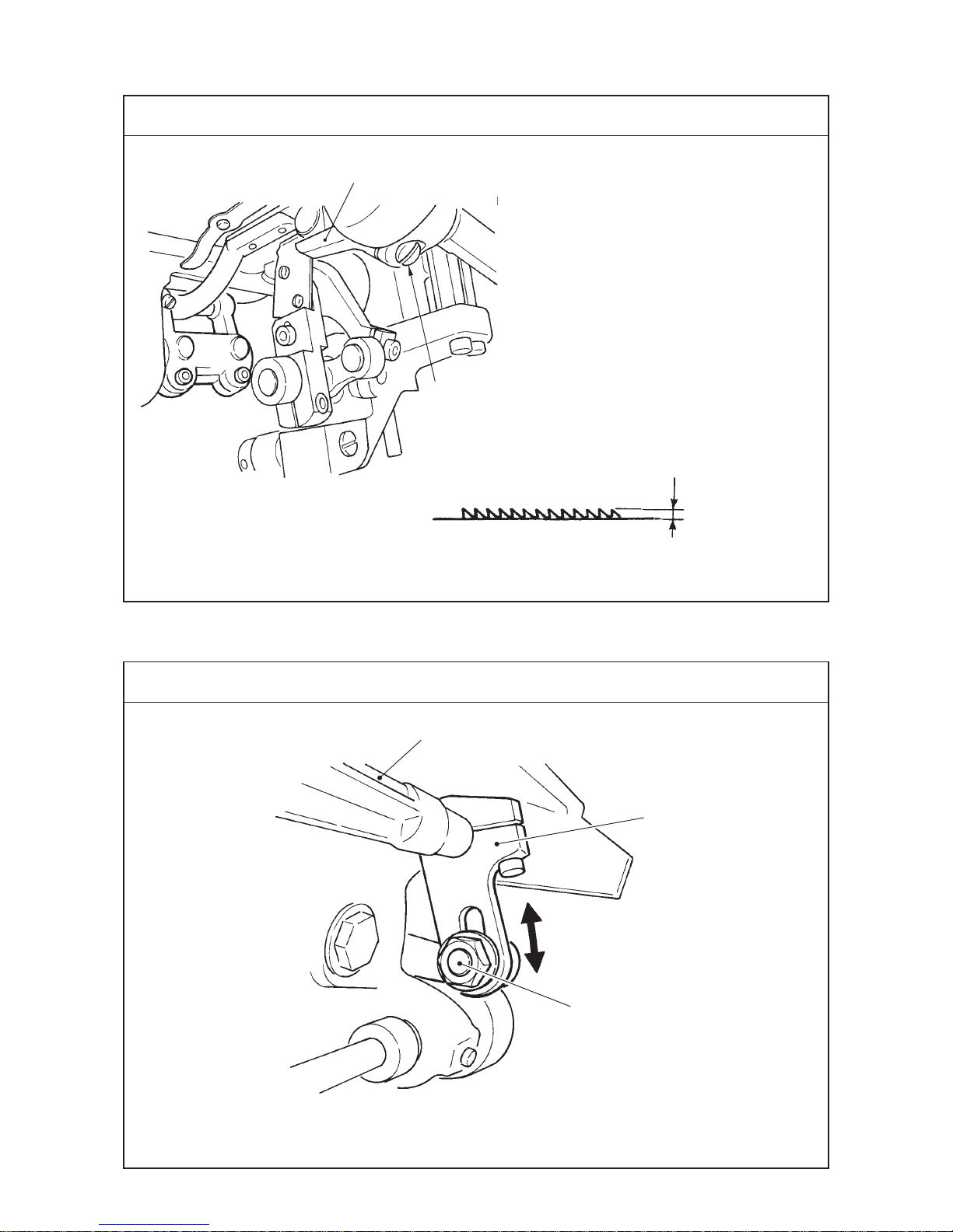
(2) Adjusting the height of the feed dog
Standard Adjustment
(3) Adjusting the vertical movement of the feed
™MP-200NS
0.4 to 0.5 mm
™MP-200NL
0.6 to 0.7 mm
1
2
Conditions : Stitch dial scale : “0”
: Turn handwheel to bring needle
bar to its upper dead point.
1
2
3

−6 −
Adjustment Procedures Results of Improper Adjustment
Adjustment Procedures Results of Improper Adjustment
1. Adjust the vertical movement of the feed at the position of lock
nut 2 in the long hole of feed driving shaft rear arm 1.
2. When the lock nut is tightened on the side of feed driving shaft
3 in the long hole, the movement is increased, and when it is
tightened on the outside (extreme top end of the long hole),
the movement is decreased.
™ MP-200NS : To fix at the extreme top end of the long hole
(Minimum feed movement)
™ MP-200NL : To fix at the position of approximately 1/3 from
the side of top end of the long hole.
(Caution) Check that there is no contact between feed dog,
loop guide and spreader.
1. Loosen setscrew 2 in feed driving fork end 1, move feed
driving fork end 1 in the direction of rotation, and adjust the
height of the feed dog.
™ MP-200NS : 0.4 to 0.5 mm
™ MP-200NL : 0.6 to 0.7 mm
(Caution) When adjustment has been performed, operate the
machine after carefully checking whether the feed
dog does not come in contact with other parts.
™ When the vertical movement is
increased, it is improved for thick
thread or cloth to be caught on
the feed dog.
™ To raise the feed dog and to
increase the vertical movement
as well are effective when stitch
gathering occurs with heavyweight material, overlapped
section, etc.
™ To decrease the vertical
movement of the feed dog can
control the flopping of material
by the feed dog. As a result, it is
effective for the process where
light-weight material or straight
sewing is required.

−7 −
Standard Adjustment
(4) Feed cam timing
d
Bottom end of metal is aligned
with 4th engraved marker line.
1
2 (Screw No. 2)
3
4
5
6 (Screw No. 1)
Standard : 2 and 6 are almost aligned
with each other.
Top surface of feed dog is
aligned with top surface of
throat plate.
d

−8 −
Adjustment Procedures Results of Improper Adjustment
1. Adjust the timing of feed rock triangle cam 1 to the position
where the feed dog does not move even moving the reverse
feed lever up or down when the 4th engraved marker line
(lowest marker line) is aligned with the bottom end of the metal
when the needle bar comes down.
2. Loosen two setscrews 2 in feed rock triangle cam 1.
3. Turn the handwheel with feed rock triangle cam 3 fixed in the
normal rotational direction to retard the feed timing, or in the
reverse direction to advance the feed timing.
4. Install feed rock triangle cam 3 so that the edge of feed rock
rod 3 comes in contact with feed eccentric cam side plate 4
of feed rock triangle cam 1.
(Caution) Turn the main shaft and check that there is no skew
between feed rock rod 3 and feed eccentric cam
side plate 4.
5. To adjust the timing of feed driving cam 5, stop the cam at the
position where the top surface of the feed dog is aligned with
the top surface of the throat plate when the top end of needle
eyelet of the sewing needle is aligned with the top surface of
the throat plate while the needle bar descends. (Alignment of
three points)
6. Loosen two setscrews 6 in feed driving cam 5.
7. Turn the handwheel with feed driving cam 5 fixed in the normal
rotational direction to retard the timing of the vertical movement,
or in the reverse direction to advance the timing.
™ When loop is not tightened in
overlapped section sewing,
retard the feed timing. Then feed
tightening is applied and loop is
tightened.
™ If the timing is excessively
advanced or retarded, the
sewing product is fed when the
needle is pierced. As a result,
needle breakage, bend of
spreader, etc. will occur.
™ When the timing between feed
rock triangle cam 1 and feed
driving cam 5 is not proper,
return is applied to the feed dog
at the end of feed or at the start
of feed. As a result, stitch
skipping will be caused.
 Loading...