

Page 1

MF-7900,7900D/UT59
INSTRUCTION MANUAL
No.00
3
70003572
Page 2

CONTENTS
I. SPECIFICATIONS .............................................................................................................1
II. AT THE BEGINNING ........................................................................................................1
III. INSTALLING THE ACCESSORIES ................................................................................2
1. Installing the air regulator ................................................................................................................... 2
2. Installing the manifold ......................................................................................................................... 2
3. Connecting the cords .......................................................................................................................... 3
4. Setting procedure of the machine head ............................................................................................. 4
IV. AIR PIPING DRAWING ...................................................................................................5
1. Piping of the thread trimmer device ................................................................................................... 5
2. Adjusting the air regulator ................................................................................................................... 5
V. THREADING THE MACHINE HEAD ...............................................................................6
VI. ADJUSTING THE LOOPER THREAD TRIMMER MECHANISM ..................................7
1. Initial position of the looper thread trimmer mechanism ................................................................. 7
VII. INSTALLING THE SS LEVER UNIT .............................................................................8
1. Installing the SS lever unit .................................................................................................................. 8
2. Adjusting the SS lever unit .................................................................................................................. 8
VIII. DRAWING OF THE TABLE ..........................................................................................9
IX. SETTING THE UPPER STOP POSITION OF THE NEEDLE BAR .............................10
X. SETTING THE RAVELING PREVENTION PARAMETER ............................................12
i
Page 3
I. SPECIFICATIONS
Model name High-speed, cylinder-bed coverstitch machine
Model MF-7900 series
Stitch type ISO standard 406, 407, 602, and 605
Example of application
Sewing speed Max. 6,000 sti/min (at the time of intermittent operation) Direct-drive type
Needle gauge 3-needle ..... 5.6 mm and 6.4 mm
2-needle ..... 4.0 mm and 4.8 mm
Differential feed ratio 1 : 0.9 to 1 : 1.4 (stitch length : less than 2.5 mm) * Only for H23
Stitch length 0.9 mm to 3.6 mm (can be adjusted up to 4.5 mm)
Needle UY128GAS #9S to #14S (standard #10S)
Needle bar stroke 31mm (33 mm when the eccentric pin is changed over)
Dimensions (Height) 450 x (Width) 456 x (Length) 299
Weight 45 kg (With pneumatic type thread trimmer)
Lift of presser foot 8 mm (needle gauge : 5.6 mm without top covering), and 5 mm (with top covering)
Feed adjustment
method
Looper mechanism Spherical rod drive method
Lubricating system Forced lubrication method by gear pump
Lubricating oil JUKI GENUINE OIL 18
Oil reservoir capacity Oil gauge lower line : 600 cc to upper line : 900 cc
Installation Table-mount type, Semi-submerged type
Noise - Equivalent continuous emission sound pressure level (LpA) at the workstation:
Main feed ............... dial type stitch pitch adjustment method
Differential feed ..... lever adjustment method (micro-adjustment mechanism is provided.)
A-weighted value of 79.5 dB; (Includes KpA = 2.5 dB); according to ISO 10821- C.6.2 -ISO 11204 GR2 at 4,500
sti/min.
For preventing thread from raveling at the end of hemming or other processes
Speed of stitch at the delivery: 4,500 sti/min (at the time of intermittent operation)
(1 : 0.6 to 1 :1 .1, when the differential link hinge screw is changed)
Micro-differential feed adjustment mechanism is provided. (Micro-adjustment)
Micro-lifter mechanism is provided.
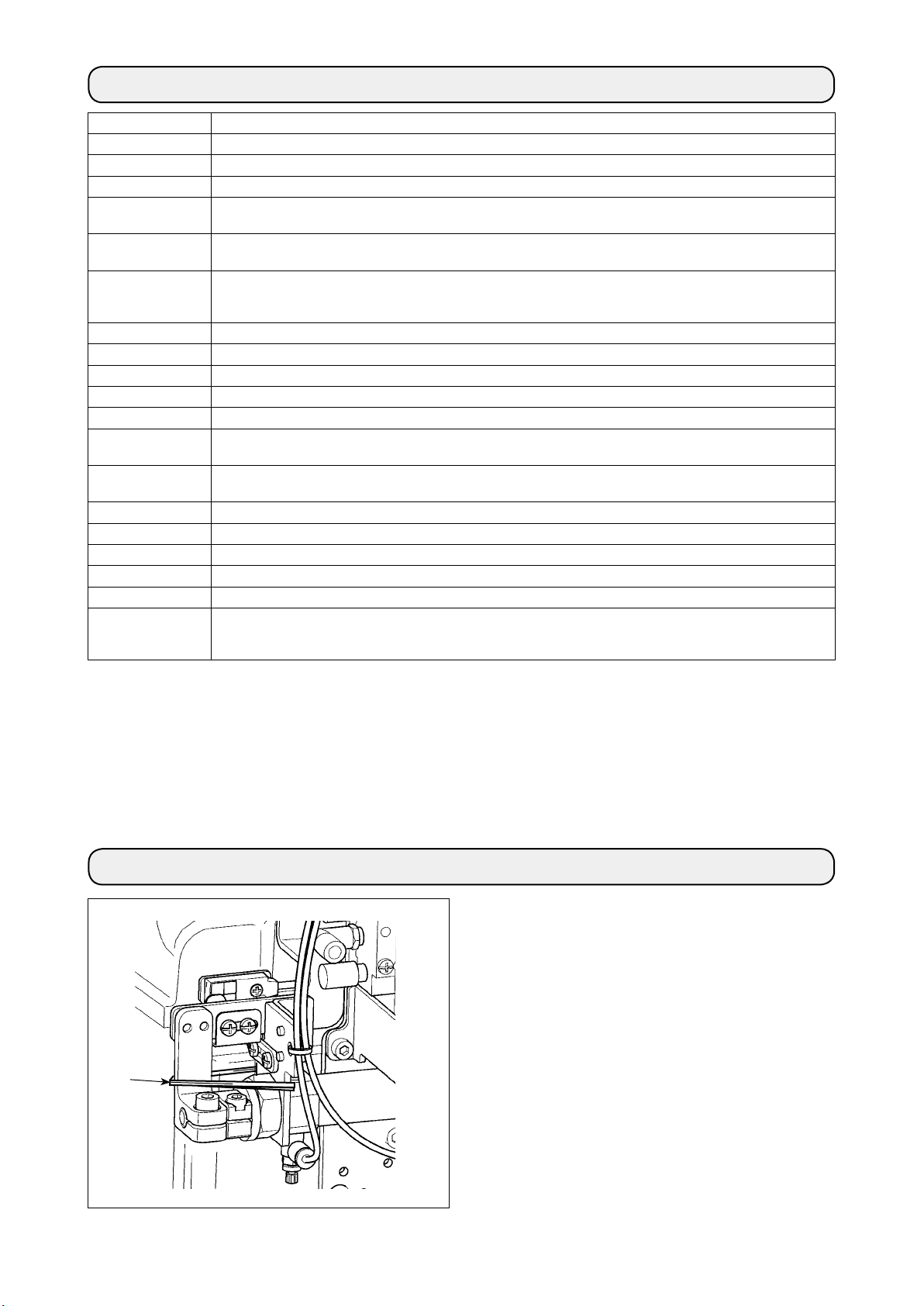
II. AT THE BEGINNING
❶
Remove xed band ❶ for transportation before setting
up the sewing machine.
– 1 –
Page 4

III. INSTALLING THE ACCESSORIES
WARNING :
To protect against possible personal injury due to abrupt start of the machine, be sure to start the
following work after turning the power off and ascertaining that the motor is at rest.
1. Installing the air regulator
❷
❶
2. Installing the manifold
1) Install air regulator asm. ❶ under the table with
wood screws ❷.
❶
❷
Install manifold asm. ❶ on the table with wood screw
.
❷
– 2 –
Page 5
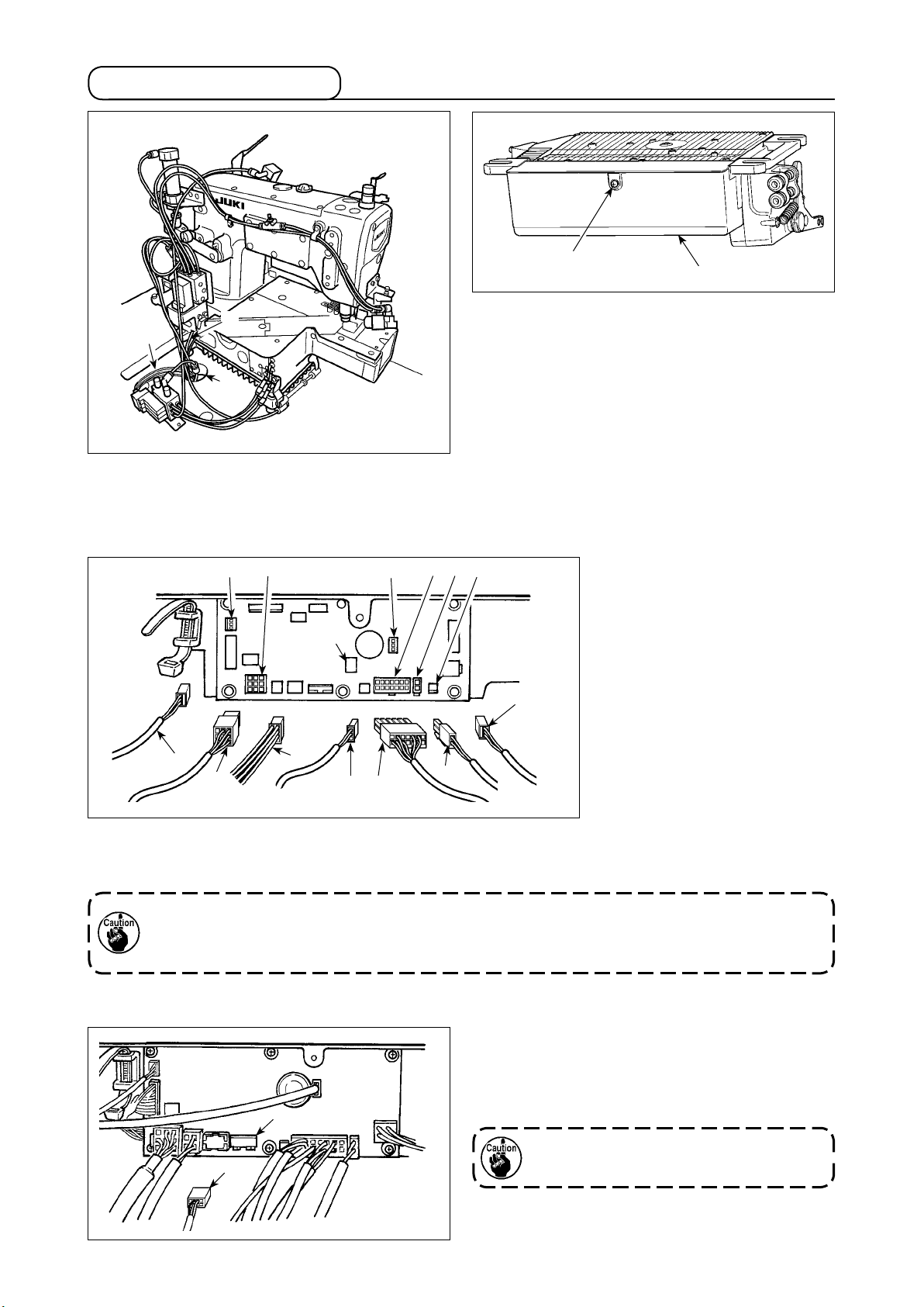
3. Connecting the cords
❶
A
1) Pass cords ❶ and of the thread-trimming solenoid, reverse feed stitching, motor signal etc. and
the motor cord through the hole A in the table to
route them to the underside of the table.
❻
❾
❺
❽
❸
B
❷
2) Loosen screw B in cover ❷ with a screwdriver to
open the cover.
❼
3) Connect 14P code ❸ coming
from the machine head to connector ❻ (CN36).
4) Insert 3P cord ❾ coming from
the machine head into connector (CN42).
5) Insert presser foot lifter cord 2P
into connector ❼ (CN37).
❹
6) Connect connector ❺ coming
from the motor to connector ❽
(CN30) on the circuit board.
❹
7) Insert pedal sensor cable into connector (CN34).
8) Insert motor fan cord into connector .
9) Insert 8P cord to connector (CN56).
Be sure to securely insert the respective connectors after checking the inserting directions since all connectors have the inserting directions. (When using a type with lock, insert the connectors until they go to the
lock.) The sewing machine is not actuated unless the connectors are inserted properly. In addition, not only
the problem of error warning or the like occurs, but also the sewing machine and the control box are damaged.
[Connecting the connector for the operation panel]
– 3 –
The connector for the operation panel is provided.
Paying attention to the orientation of the connector ,
connect it to connector (CN38) located on the circuit
board. After the insertion, securely lock the connectors
to prevent them from coming off easily.
Be sure to turn OFF the power before connecting the connector.
Page 6

4. Setting procedure of the machine head
For the operation panel other than CP-18, refer to the Instruction Manual for the operation panel to be used
for the setting procedure of the machine head.
1) Call function setting No. 95.
❸❷❶
❹
2) The type of machine head can be se-
lected by pressing
switch ❸ (
switch ❹).
* Refer to the
"MACHINE HEAD LIST"
on the separate sheet or the Instruction Manual for the machine head of
your sewing machine for the type of
the machine head.
❸❷❶
❹
Type of machine head Model name
F799 MF-7900/UT59
3) After selecting the type of machine
head, by pressing switch ❶ (
switch ❷), the step proceeds to 96
or 94, and the display automatically
changes to the contents of the setting
corresponding with the type of machine head.
❸❷❶
❹
– 4 –
Page 7

IV. AIR PIPING DRAWING
WARNING :
To protect against possible personal injury due to abrupt start of the machine, be sure to start the
following work after turning the power off and ascertaining that the motor is at rest. In addition, cut the air
supply from air compressor.
1. Piping of the thread trimmer device
2. Adjusting the air regulator
❷
Air hose
❶
❸
A
1) Insert the air hose to air regulator ❶.
2) Use the air pressure at 0.4 to 0.5 MPa (4 to 5 kgf/
cm2).
3) Draw up regulator knob ❷, turn knob ❷ and adjust the pointer to 0.4 to 0.5 MPa to adjust the air
pressure.
4) After the adjustment, press downward regulator
knob ❷.
5) When drainage is collected at section A of regulator ❶ during using, press drain cock ❸ to discharge the drainage.
– 5 –
Page 8

V. THREADING THE MACHINE HEAD
WARNING :
To protect against possible personal injury due to abrupt start of the machine, be sure to start the
following work after turning the power off and ascertaining that the motor is at rest. If threading is wrong,
stitch skipping, thread breakage, needle breakage or irregular stitches will be caused. So, be careful.
Thread the machine head according to the following threading illustrations.
❷
❶
* For the adjustment procedure other than the above, refer to the Instruction Manual for MF-7900.
When the small thread tension in the face plate is used for the machine with the thread trimmer device,
the length of remaining needle thread after thread trimming becomes short and slip-off of thread at the
start of sewing may occur.
❶
❷
– 6 –
Page 9

VI. ADJUSTING THE LOOPER THREAD TRIMMER MECHANISM
WARNING :
To protect against possible personal injury due to abrupt start of the machine, be sure to start the
following work after turning the power off and ascertaining that the motor is at rest. In addition, cut the air
supply from air compressor.
❹
24 ± 0.5 mm
Center of needle
bar
1. Initial position of the looper thread trimmer mechanism
When lower knife ❹ is located at its leftmost position,
the top end of the lower knife ❹ has to be spaced 24 ±
0.5 mm from the center of needle bar.
Perform the work with the needle bar at the
highest position when actuating the thread
trimmer mechanism by hand.
– 7 –
Page 10

VII. INSTALLING THE SS LEVER UNIT
WARNING :
To protect against possible personal injury due to abrupt start of the machine, be sure to start the
following work after turning the power off and ascertaining that the motor is at rest.
1. Installing the SS lever unit
❸
❷
❶
❹
1) Install SS lever unit ❹ using SS lever unit setscrews 1 ❶, SS lever unit setscrews 2 ❷ and SS lever unit
washers ❸ supplied as accessories.
* Temporarily tighten SS lever unit setscrews 2 ❷ at the center position of the slot and securely tight-
en the setscrews after performing the trial sewing and adjusting the stitch pitch of the short stitch.
Inaddition,installtheSScoverafternishingtheworkofsecurelytighteningofthesetscrews.
Refer to "2. Adjusting the SS lever unit" p.8 for how to adjust and install the SS lever unit.
2. Adjusting the SS lever unit
WARNING :
To protect against possible personal injury due to abrupt start of the machine, be sure to start the
following work after turning the power off and ascertaining that the motor is at rest. In addition, cut the air
supply from air compressor.
❷
❸
B
A
❶
❹
1) Loosen setscrews ❷ in SS lever ❶, move the lever up and down to adjust the position, and the stitch pitch
of the short stitch can be adjusted.
* Commendable stitch pitch is 1.4 mm. (The center position of the slot of SS lever is the standard.)
Turn SS lever ❶ in the direction of A to increase the stitch pitch, and turn it in the direction of B to decrease
the stitch pitch.
2)
When the adjustment is completed, install SS cover ❹ using setscrew ❸ supplied as accessories. Setscrew ❺ has to
be tightened together with the pitch scale plate.
❺
– 8 –
Page 11

VIII. DRAWING OF THE TABLE
DRAWING OF TABLE (SEMI-SUBMERGED TYPE) H22/23-UT59 DIRECT-DRIVE TYPE
Drilled hole 17
4 - 10.5 hole, 26 hole facing
depth 3.5
(Drill a hole at the time
of set-up.)
Z-Z (four locations)
2 - ø 3.4 on the bottom surface, depth 10
Installing position of drawer
stopper (on the reverse side)
(Drill a hole at the
time of set-up.)
4 - ø 3.4 on the bottom
surface, depth 20
– 9 –
Page 12

IX. SETTING THE UPPER STOP POSITION OF THE NEEDLE BAR
❸
Ⓐ
1) Simultaneously pressing switch
and switch ❺, turn ON the
❹
power switch.
2) is displayed (Ⓐ) in the indica-
tor and the mode is changed over to
the adjustment mode.
❺❹
❻
Ⓑ
3) Give the pulley of the machine head
a turn by hand. Then, the main shaft
reference signal is detected. The
degree of an angle given by the main
shaft reference signal is indicated on
display section Ⓑ with a blip.
(The value is the reference value.)
❷
❺❹❸
❶
❻
4) In this state, give the pulley of the machine head
another turn by hand to align marker line ❶ on the
hand pulley with recess ❷ in the frame as shown
in the gure.
The direction of rotation is clockwise. If the
pulley is turned counterclockwise, the degree
of the aforementioned angle can differ by
approximately two degrees.
Ⓑ
5) Press switch ❻.
(The value is the reference value.)
Take a note of the numeric value
shown on display section Ⓑ since it is
used for
"X. SETTING THE RAVELING PREVENTION PARAMETER"
p.12"
.
❺❹❸
❻
– 10 –
Page 13

When the needle
moves in the
descending
direction
6) Remaining in the needle-bar upper stop position
setting mode, turn the hand pulley of the machine
head by hand to lower the needle until the position
where its tip is aligned with the center of the looper
is reached. Keeping the needle at that position,
take a note of the numeric value shown on display
section Ⓑ. It is necessary to take a note of the
numeric value shown on display section Ⓑ since it
is used for
VENTION PARAMETER" p.12"
"X. SETTING THE RAVELING PRE-
.
If you press switch ❻ in this state, the
upper stop position of the needle bar is set
again. To prevent this, be sure to turn off the
power once without pressing any switch.
Ⓑ
❺❹❸
❻
The direction of rotation is clockwise. If the pulley is turned counterclockwise, the degree of the
aforementioned angle can differ
by approximately two degrees.
– 11 –
Page 14

X. SETTING THE RAVELING PREVENTION PARAMETER
Ⓓ
Ⓒ
❷
❶
Ⓐ
Ⓑ
1) Turn ON the power with switch
held pressed.
❼
(The item which has been changed
during the previous work is displayed.)
* If the screen display does not change,
re-carry out operation described in
step 1).
(Caution)
❻❺❹❸
Ⓔ
❼
Be sure to re-turn ON the power
switch when one or more seconds
have passed after turning it OFF. If the
power switch is re-turned ON immediately after turning it OFF, the sewing
machine may fail to operate normally.
In such a case, be sure to turn ON the
power switch again properly.
2) Press switch ❸ or switch ❹
to set the setting number at 128. The
current set value is shown on display
section Ⓑ.
Press switch ❺ or switch ❻
to lower the left needle until its tip is
aligned with the center of the looper.
At this time, read the displayed value.
Change the value shown on display
❺❹❸
❻
section Ⓑ to a value which is obtained by subtracting the value shown
on display section Ⓑ in 5)
"IX. SETTING THE UPPER STOP POSITION
OF THE NEEDLE BAR" p.10
from
the aforementioned value.
Example) The value shown on display section Ⓑ in 5)
NEEDLE BAR" p.10
is 5. The value displayed when the descending left needle tip is aligned with the cen-
"IX. SETTING THE UPPER STOP POSITION OF THE
ter of the looper is 90. Subtract the former value 5 from the latter value 90. (i.e., 90 - 5 = 85)
Press switch ❺ or switch ❻ to change the value shown on display section Ⓑ to 85.
3)
After completion of the changing procedure, press switch ❸ or switch ❹ to conrm the updated value.
(Caution) If the power is turned OFF before carrying out this procedure, the changed content is not updated.
When switch ❸ is pressed, the display on the panel changes to the previous setting No. When
switch ❹ is pressed, the display on the panel changes to the subsequent setting No. After completion
of the operation, the machine is returned to the normal sewing state by turning OFF the power and
re-turning it ON.
– 12 –
 Loading...