

JUKI MF-7900D/UT55, MF-7900D/UT57, MF-7900D/UT56, MF-7900/UT55, MF-7900/UT57 Instruction Manual
...Page 1

MF-7900(D)/UT55,56,57
INSTRUCTION MANUAL
No.01
2
70002031
Page 2

CONTENTS
!
. SPECIFICATIONS ..........................................................................................................1
@
. AT THE BEGINNING ......................................................................................................1
#
. INSTALLING THE ACCESSORIES ...............................................................................2
1. Installing the presser lifting cylinder ............................................................................................ 2
2. Installing the air regulator .............................................................................................................. 2
3. Installation and setting SC-921 ...................................................................................................... 3
(1) Installing the SC-921 on the table ( Table-mount type ) ............................................................................3
(2) Installing the SC-921 on the table ( Semi-submerged type ) ....................................................................3
(3) Connecting the cords ...................................................................................................................................4
(4) Setting procedure of the machine head .....................................................................................................5
(5) Setting the lower stop position of the needle bar .....................................................................................6
$
. AIR PIPING DRAWING ..................................................................................................7
1. Piping of the thread trimmer device (UT57) .................................................................................. 7
2. Piping of the thread trimmer device (UT55) .................................................................................. 8
3. Piping drawing for air blow (UT56) ................................................................................................ 9
4. Adjusting the air regulator ............................................................................................................. 9
%
. THREADING THE MACHINE HEAD ...........................................................................10
^
. ADJUSTING THE LOOPER THREAD TRIMMER MECHANISM ................................11
1. Adjusting the thread trimmer air cylinder ....................................................................................11
2. Adjusting the Lower knife ............................................................................................................ 12
3. Adjusting the position of clamp pressure adjusting spring ..................................................... 12
4. Adjusting the knife engagement and the knife pressure adjusting spring ............................. 12
5. Adjusting the pressure of clamp spring ..................................................................................... 12
6. Initial position of the looper thread trimmer mechanism .......................................................... 13
7. Adjusting the stopper ................................................................................................................... 13
8. Adjusting the height of the lower knife ....................................................................................... 13
9. Adjusting the lower knife holder guide ....................................................................................... 13
10. Adjusting the longitudinal position of the blade point of lower knife ...................................... 14
11. Adjusting the thread trimmer sensor .......................................................................................... 14
12. Adjusting the speed of looper thread trimmer ........................................................................... 14
&
. ADJUSTING THE THREAD RELEASE MECHANISM ................................................15
1. Adjusting the disk-rise ................................................................................................................. 15
2. Adjusting the thread release hook .............................................................................................. 15
*
. ADJUSTING THE TOP COVERING THREAD TRIMMER MECHANISM ....................16
1. Adjusting the engagement of knives .......................................................................................... 16
2. Adjusting the pressure of clamp spring ..................................................................................... 16
3. Adjusting the position of the blade point of moving knife ........................................................ 16
4. Adjusting the speed of moving knife .......................................................................................... 17
(
. ADJUSTING THE AIR-BLOW WIPER (UT56) .............................................................18
1. Installing the air-blow wiper ......................................................................................................... 18
2. Adjusting the air-blow wiper ........................................................................................................ 18
)
. ADJUSTING THE NEEDLE THREAD WIPER (UT55) ................................................19
1. Adjusting the clamp spring .......................................................................................................... 19
2. Installing the needle thread wiper ............................................................................................... 19
_
. MAINTENANCE ...........................................................................................................20
1. Cleaning the motor fan ................................................................................................................. 20
i
Page 3
!
. SPECIFICATIONS
Model name High-speed, cylinder-bed coverstitch machine Semi-dry head, high-speed, cylinder-bed
coverstitch machine
Model MF-7900 series MF-7900D series
Stitch type ISO standard 406, 407, 602, and 605
Example of application
Sewing speed Max. 6,500 sti/min (at the time of intermittent operation)
V-belt type
Max. 6,000 sti/min (at the time of intermittent operation)
Direct-drive type
Speed of stitch at the delivery:
4,500 sti/min (at the time of intermittent operation)
Needle gauge 3-needle .....5.6 mm and 6.4 mm
2-needle ..... 3.2 mm, 4.0 mm and 4.8 mm
Differential feed ratio 1 : 0.9 to 1 : 1.8 (stitch length : less than 2.5 mm)
Micro-differential feed adjustment mechanism is provided. (Micro-adjustment)
Stitch length 0.9 mm to 3.6 mm (can be adjusted up to 4.5 mm)
Needle
Needle bar stroke 31mm (33 mm when the eccentric pin is changed over)
Dimensions (Height) 450 x (Width) 456 x (Length) 299
Weight 45 kg (With pneumatic type thread trimmer) , 42 kg
Lift of presser foot 8 mm (needle gauge : 5.6 mm without top covering), and 5 mm (with top covering)
Feed adjustment
method
Looper mechanism Spherical rod drive method
Lubricating system Forced lubrication method by gear pump
Lubricating oil JUKI GENUINE OIL 18
Oil reservoir capacity Oil gauge lower line : 600 cc to upper line : 900 cc
Installation Table-mount type, Semi-submerged type
Noise - Equivalent continuous emission sound pressure level
UY128GAS #9S to #14S (standard #10S) UY128GAS #9S to #12S (standard #10S)
Main feed ............... dial type stitch pitch adjustment method
Differential feed ..... lever adjustment method (micro-adjustment mechanism is provided.)
(LpA) at the workstation:
A-weighted value of 79.5 dB; (Includes KpA = 2.5 dB);
according to ISO 10821- C.6.2 -ISO 11204 GR2 at
4,500 sti/min.
Hemming and covering for knits and general knitted fabrics
Max. 5,000 sti/min (at the time of intermittent operation)
V-belt type
Max. 5,000 sti/min (at the time of intermittent operation)
Direct-drive type
Speed of stitch at the delivery:
4,000 sti/min (at the time of intermittent operation)
(1 : 0.6 to 1 :1 .1, when the differential link hinge screw is changed)
Micro-lifter mechanism is provided.
- Equivalent continuous emission sound pressure level
(LpA) at the workstation:
A-weighted value of 76.5 dB; (Includes KpA = 2.5 dB);
according to ISO 10821- C.6.2 -ISO 11204 GR2 at
4,000 sti/min.
@
. AT THE BEGINNING
1
Remove xed band 1 for transportation before setting
up the sewing machine.
– 1 –
Page 4
#
INSTALLING THE ACCESSORIES
.
WARNING :
To protect against possible personal injury due to abrupt start of the machine, be sure to start the
following work after turning the power off and ascertaining that the motor is at rest.
1. Installing the presser lifting cylinder
4,7
3
1
8
1 to 2mm
2
5
9
6
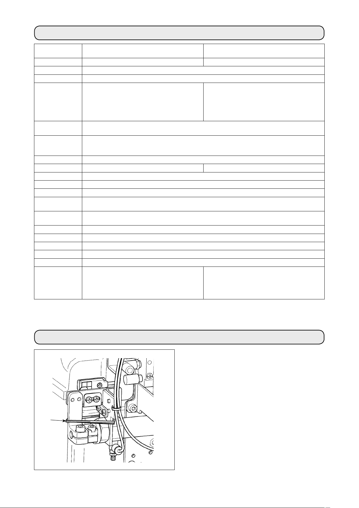
2. Installing the air regulator
1) Install presser lifting cylinder asm.
machine with screws
washers 7.
2) Tighten screw 3 in such manner that a clearance
of 1 to 2 mm is provided between cap
end of presser lifting cylinder asm.
lifting lever
If the clearance cannot be adjusted to 1 to 2 mm,
adjust the height of nut
correct clearance between the cap and lever.
3) Adjust the height of screw 5 referring to the
Instruction Manual for MF-7900 (
the presser foot lift
4) Stroke of cylinder asm. 1 is 30 mm. Make sure
that presser lifting lever 2 comes in contact with
screw 5 within the range of cylinder stroke.
2
.
, washers
3
and cap
8
),
and tighten nut
to the sewing
1
and spring
4
9
and presser
1
to obtain the
9
^
Adjusting
-14.
.
6
at the top
2
1) Install air regulator asm. 1 under the table with
wood screws 2.
1
– 2 –
Page 5
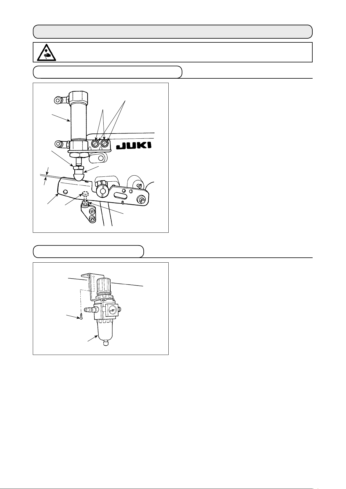
3. Installation and setting SC-921
(1) Installing the SC-921 on the table ( Table-mount type )
* The instructions apply to the case the control box is installed on the table of the MF-7900(D).
To use any other machine head, install the control box on the table referring to the Instruction Manual for the
main body of the relevant sewing machine.
1
Fig. B
4
Fig. A
Convex
washer
Spring
washer
Hexagonal nut
1
6
5
6
2
1) Install control box 2 on the table with mounting bolt asm. 1 supplied with the unit.
At this time, insert the nuts and washers supplied with the unit as illustrated in Figure A so that the support
plates and the control box 2 are securely xed.
2) Install the control box 2 (or the one equipped with a small sized motor unit) on the table. Then, install the
sewing machine head on the table. (Refer to the Instruction Manual for the sewing machine.)
3) Install the mounting plate on the CP-18 panel 5 with four tapping screws 4 supplied with the unit.
At this time, take care not to allow the cable to be caught under the mounting bracket.
(Install the CP-18 on the table as illustrated in Fig.
4) Install CP-18 panel 5 on the table with wood screw
.)
B
.
6
(2) Installing the SC-921 on the table ( Semi-submerged type )
1) Install right and left support plates 7 and two
1
!0
8
7
!1
9
2
rubber seats
2) Install control box mounting plate 9 on the
control box with four screws
3) Install the parts assembled in Step 2) on the
underside of support plates 7 with four screws
.
!1
4) Install support plates 7 and the control box
on the table with mounting bolts asm. 1
2
supplied with the unit. At this time, insert the
nuts and washers supplied with the unit as
illustrated in Figure A so that the support plates
and the control box 2 are securely xed.
* The steps of procedure from the next one and
beyond are same with those for the table-xed
type machine head.
of the respective support plates.
8
.
!0
– 3 –
Page 6
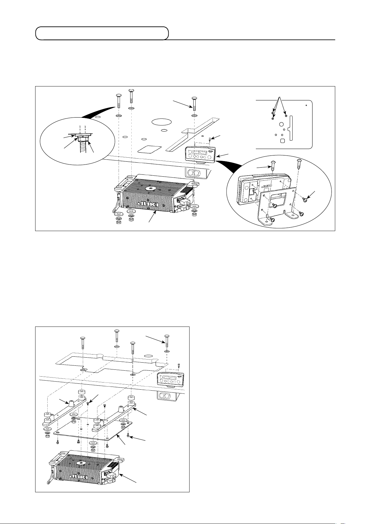
(3) Connecting the cords
1
A
1) Pass cords 1 of the thread trimming solenoid,
reverse-stitching solenoid, etc. and the cord from
the motor through hole A in the table to route them
down under the machine table.
!1
!2!0
3
8
9
5
2) Loosen screw
7
!4
6
4
B
open the cover.
!3
2
in cover 2 with a screwdriver to
B
3) Connect 14P code 3 coming
from the machine head to
connector 6 (CN36).
4) Insert 3P cord 9 coming
from the machine head into
connector !0 (CN42).
5) Insert presser foot lifter cord 2P
into connector 7 (CN37).
4
6) Connect connector 5 coming
from the motor to connector 8
(CN30) on the circuit board.
7) Insert pedal sensor cable !1 into connector !2 (CN34).
8) Insert motor fan cord !3 into connector !4.
Be sure to securely insert the respective connectors after checking the inserting directions since all connectors have the inserting directions. (When using a type with lock, insert the connectors until they go to
the lock.) The sewing machine is not actuated unless the connectors are inserted properly. In addition, not
only the problem of error warning or the like occurs, but also the sewing machine and the control box are
damaged.
[Connecting the connector for the operation panel]
!6
!5
The connector for the operation panel is provided.
Paying attention to the orientation of the connector !5,
connect it to connector (CN38) !6 located on the circuit
board. After the insertion, securely lock the connectors
to prevent them from coming off easily.
Be sure to turn OFF the power before connecting the connector.
– 4 –
Page 7
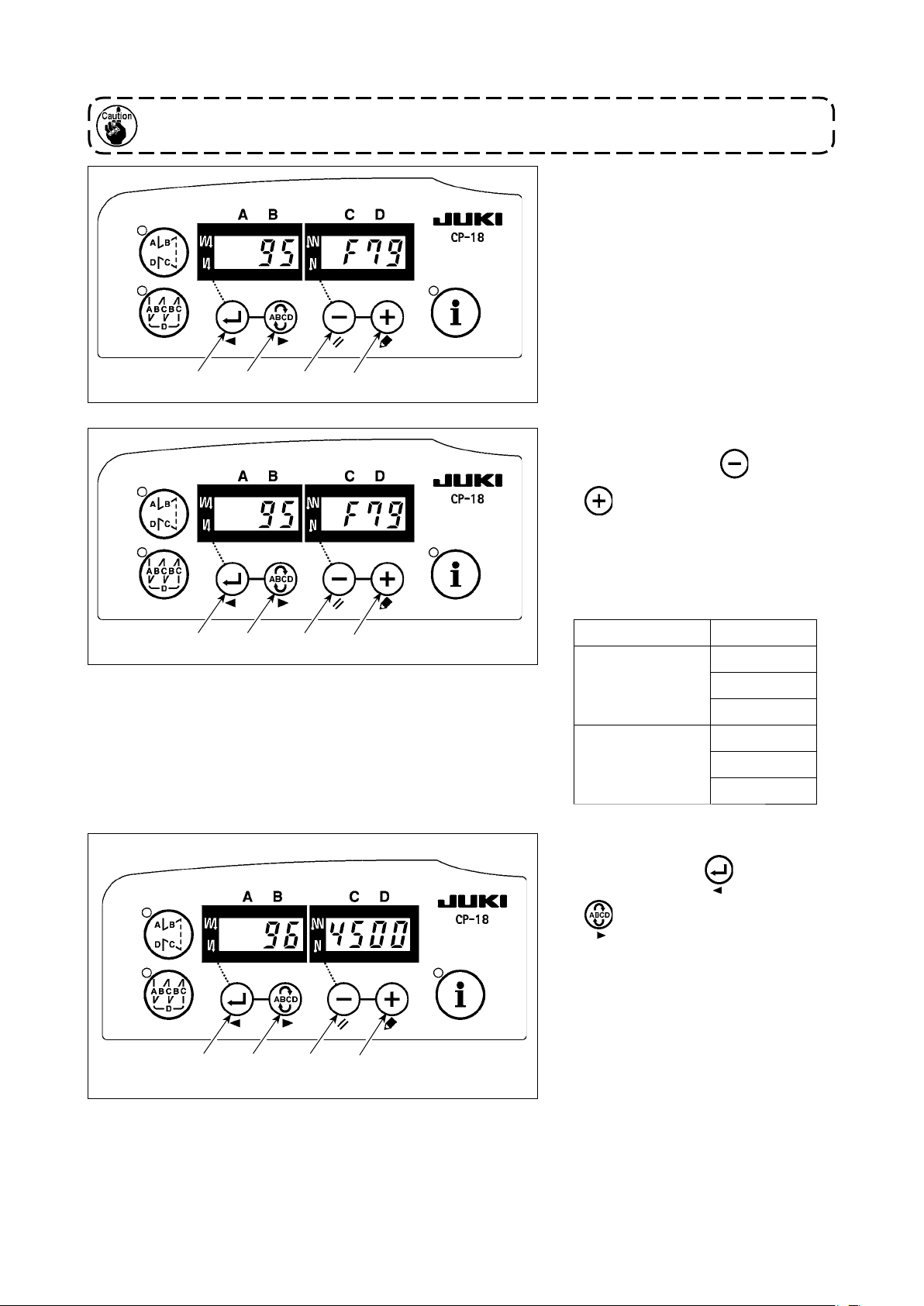
(4) Setting procedure of the machine head
For the operation panel other than CP-18, refer to the Instruction Manual for the operation panel to be used
for the setting procedure of the machine head.
1) Call function setting No. 95.
321
4
2) The type of machine head can be
selected by pressing
switch 4).
* Refer to the
on the separate sheet or the
LIST"
"MACHINE HEAD
switch 3 (
Instruction Manual for the machine
head of your sewing machine for the
type of the machine head.
321
4
Type of machine head Model name
MF-7900/UT55
F79
F79d
MF-7900/UT56
MF-7900/UT57
MF-7900D/UT55
MF-7900D/UT56
MF-7900D/UT57
3) After selecting the type of machine
head, by pressing switch
1
(
switch 2), the step proceeds to
96 or 94, and the display automatically
changes to the contents of the
setting corresponding with the type of
machine head.
321
4
– 5 –
Page 8

(5) Setting the lower stop position of the needle bar
Call function setting No. 122. Check to
be sure that the lower stop position of
the needle bar is as shown in
not, adjust the lower stop position of the
needle bar properly using function setting
No. 122. (Adjustment can be made within
the range of ±15°).
Fig. 1
. If
Fig. 1
321
4
– 6 –
Page 9

$
. AIR PIPING DRAWING
WARNING :
To protect against possible personal injury due to abrupt start of the machine, be sure to start the
following work after turning the power off and ascertaining that the motor is at rest. In addition, cut the air
supply from air compressor.
1. Piping of the thread trimmer device (UT57)
3
4
!1
@3
2
!1
9
9
9
!0
!0
!1
1
– 7 –
Page 10

2. Piping of the thread trimmer device (UT55)
3
4
@3
!1
9
– 8 –
Page 11

3. Piping drawing for air blow (UT56)
3
4
5
3
3
5
6
@3
4. Adjusting the air regulator
2
Air hose
1
3
@3
A
2
1
1) Insert the air hose to air regulator
1
.
2) Use the air pressure at 0.4 to 0.5 MPa (4 to 5 kgf/
cm2).
3) Draw up regulator knob
, turn knob 2 and adjust
2
the pointer to 0.4 to 0.5 MPa to adjust the air
pressure.
4) After the adjustment, press downward regulator
knob 2.
5) When drainage is collected at section A of
regulator
during using, press drain cock
1
3
to
discharge the drainage.
– 9 –
Page 12

%
. THREADING THE MACHINE HEAD
WARNING :
To protect against possible personal injury due to abrupt start of the machine, be sure to start the
following work after turning the power off and ascertaining that the motor is at rest. If threading is wrong,
stitch skipping, thread breakage, needle breakage or irregular stitches will be caused. So, be careful.
Thread the machine head according to the following threading illustrations.
2
1
* For the adjustment procedure other than the above, refer to the Instruction Manual for MF-7900.
When the small thread tension in the face plate is used for the machine with the thread trimmer device,
the length of remaining needle thread after thread trimming becomes short and slip-off of thread at the
start of sewing may occur.
1
2
– 10 –
Page 13

^
ADJUSTING THE LOOPER THREAD TRIMMER MECHANISM
.
WARNING :
To protect against possible personal injury due to abrupt start of the machine, be sure to start the
following work after turning the power off and ascertaining that the motor is at rest. In addition, cut the air
supply from air compressor.
1. Adjusting the thread trimmer air cylinder
1) Stroke of air cylinder 3 is 18 mm.
2
1
3
18 mm
When adjusting the stroke, loosen setscrew
collar 1 and move collar
adjust.
1
of
2
to the right or left to
– 11 –
Page 14

4
0.5 mm
4
65.5 mm
2.5 ± 0.5 mm
!0
8
7
6
5
9
2. Adjusting the Lower knife
1) Set lower knife 4 and lower knife holder 5 with
setscrews 6 at the position of the illustration.
3. Adjusting the position of clampAdjusting the position of clamp pressure adjusting spring
1) Loosen screws 9.
2) Adjust so that a clearance of 2.5 ± 0.5 mm is
provided between the top end of clamp pressure
adjusting spring !2 and the top end of lower
knife 4 when the lower knife 4 is brought to the
rightmost position.
3) After the adjustment, tighten screws 9.
4. Adjusting the knifeAdjusting the knife engagement and the knife pressure adjusting spring
1) Loosen screws 7 and 8, and adjust the position
of upper knife !0 so that the engagement of the
upper knife !0 with the lower knife is 0.5 mm when
lower knife 4 moves to the extreme right.
2) At the same time, adjust so that a clearance of
0.5 to 1 mm is provided between knife pressure
adjusting spring !1 and clamp pressure adjusting
spring !2.
3) After the adjustment, tighten screws 7.
!2
4
!1
Clearance of 0.5 to 1 mm
!2
5. Adjusting the pressure of clamp spring
1) The looper thread is held by clamp pressure
adjusting spring !2 after thread trimming.
2) Holding pressure of the looper thread can be
adjusted by turning screw 8.
3) When screw 8 is turned clockwise, the holding
pressure is increased and turned counterclockwise,
the pressure is decreased.
4) Make the holding pressure as low as possible
within the range of holding the looper thread.
!1
– 12 –
Page 15

4
Center of needle
bar
6. Initial position of the looper thread trimmer mechanism
When lower knifeknife 4 is located at its leftmost position,
the top end of the lower knifeknife
0.5 mm from the center of needle bar.
has to be spaced 22 ±
4
22 ± 0.5 mm
!4
0 to 0.1 mm
!3
4
!2
0.3 to 1 mm
7. Adjusting the stopper
Check the leftmost point with the pneumatic device
turned on. Adjustment should be carried out with the air
pressure set at 0.5 MPa.
Adjust the position of stopper
0.3 to 1 mm is provided between looper !3 and clampclamp
pressure adjusting spring !2 when the counter knife is
located at its leftmost position (forward end).
so that a clearance of
!4
8. Adjusting the height of the lower knife
When the needle is positioned at its upper dead point,
the clearance of 0 to 0.1 mm has to be provided between the under surface of lower knife
surface of looper !3.
Perform the work with the needle bar at the
highest position when actuating the thread
trimmer mechanism by hand.
and the top
4
!3
9. Adjusting the lower knife holder guide
When the lower knife moves from right to left, the lower
knife guide holder should lightly comes in contact with
the guide.
Light contact
– 13 –
Page 16

Blade point of lower knife is in the
center of thickness of looper.
!3
9 mm
4
!5
5
10. Adjusting the longitudinal position of the blade point of lower knife
1) Bring the needle bar to its highest position.
2) Adjust so that the blade point of lower knife 4 is in
the center of the thickness of looper !3 when the
clearance between the right-hand edge of looper
and the blade point of lower knife 4 is 9 mm.
!3
3) Loosen nut !5, move lower knife holder 5 to and
fro, and adjust the position of the blade point of
lower knife 4.
4) After the adjustment, tighten nut !5.
Perform the work with the needle bar at the
highest position when actuating the thread
trimmer mechanism by hand.
!7
!6
!8
@2
3
@3
11. Adjusting the thread trimmer sensor
The safety switch is installed so that the sewing machine does not start unless the looper thread trimmer
device returns to its home position.
1) Loosen setscrews !6.
2) Adjust switch plate !7 so that LED of thread
trimmer sensor !8 lights up in the state that the
thread trimmer device is fully returned to its home
position.
3) Tighten setscrews !6.
Perform the work with the needle bar at the
highest position when actuating the thread
trimmer mechanism by hand.
12. Adjusting the speed of looper thread trimmer
Speed of the looper thread trimmer device can be
changed with speed controllers @2 and @3 of air cylinder
.
3
1) When you desire to change the protruding speed of
lower knife, loosen the nut of speed controller @2,
and turn the adjustment screw.
When you desire to change the returning speed of
lower knife, loosen the nut of speed controller @3,
and turn the adjustment screw.
2) After the adjustment, tighten the nuts of speed
controllers @2 and @3.
– 14 –
• When the protruding speed of lower knife is
slow, thread trimming failure will be caused.
• When the returning speed of lower knife is
fast, lower thread clamp failure or uneven
needle thread remaining length will be
caused.
Page 17

&
ADJUSTING THE THREAD RELEASE MECHANISM
.
WARNING :
To protect against possible personal injury due to abrupt start of the machine, be sure to start the
following work after turning the power off and ascertaining that the motor is at rest. In addition, cut the air
supply from air compressor.
*A
Clearance between click and disk is 0.2 to 0.5 mm.
(5 places)
9
7
4
1
2
3
5
!0
45 ± 1mm
*A
6
8
1. Adjusting the disk-rise
.
, turn
1
moves up
3
to 0.2
4
1) Loosen setscrew 2 in adjustment cam
adjustment cam
or down.
2) Adjust the clearance between the click section of
disk-rise plate 3 and thread tension disk
to 0.5 mm, and tighten setscrew
3) If the click section of disk-rise plate 3 comes in
contact with thread tension disk 4, sewing trouble
will be caused. So, be careful.
and disk-rise plate
1
2
2. Adjusting the thread release hook
1) Loosen setscrew
tension release rod 6 is spaced 45 ± 1 mm from
the top end of take-up thread guide
tighten setscrew
2) Loosen setscrew 9, move the position of thread
release hook 8 up or down, and the thread
remaining length at the start of sewing can be
adjusted.
• When the position of thread release hook 8 is
raised, the thread remaining length at the start
of sewing is decreased and when it is lowered,
the thread remaining length at the start of
sewing is increased.
• If stitch skipping occurs at the beginning of
sewing when using non-elastic thread, properly
adjust the remaining length of top-covering
thread at the start of sewing using setscrew !0
and minimize the remaining length of looper
thread at the start of sewing using screw !1.
. Adjust so that the top end of
5
. Then,
7
.
5
!1
When the thread remaining length at the start
of sewing is short, stitch skipping or slip-off
of thread from needle eyelet at the start of
sewing is apt to occur.
– 15 –
Page 18

*
. ADJUSTING THE TOP COVERING THREAD TRIMMER MECHANISM
WARNING :
To protect against possible personal injury due to abrupt start of the machine, be sure to start the
following work after turning the power off and ascertaining that the motor is at rest. In addition, cut the air
supply from air compressor.
1. Adjusting the engagement of knives
1) Adjust so that the engagement of xed knife 1
with moving knife 2 is 0.5 mm.
4
5
2) When adjusting the engagement, loosen setscrews
and move knife holder 5 up or down to adjust.
4
2. Adjusting the pressure of
1
!0
2
8
7
0.5 mm
6
3
!2
clamp spring
1) Top covering thread is held with clamp spring
after thread trimming.
2) Holding pressure can be adjusted by loosening nut
and turning screw 7.
6
3) Holding pressure is increased when tightening
screw 7 and it is decreased when loosening screw
.
7
4) After the adjustment, tighten nut 6.
5) Make the holding pressure as low as possible
within the range of holding the top covering thread.
3
!1
9
2
9
2
0.5 mm
3. Adjusting the position of the blade point of moving knife
1) Bring the needle bar to its highest position.
2) When hinge screw 8 is lowered, moving knife
lowers together.
3) Adjust so that the hook of moving knife 2 enters
the recess in the top face of spreader 9 to be
brought to the position where the moving knife
catches the top covering thread when moving
knife 2 is brought to the lowermost position. Then,
tighten screws !0, !1 and !2.
Adjust the moving knife vertically so that a
clearance of 0.5 mm is provided between the
recess section of spreader 9 and the moving knife,
and laterally so that the moving knife 2 is brought
to the center of the width of recess in spreader, as
illustrated in Figure A.
4) Screws !2 are for adjusting vertical position of the
knife, screws !0 for adjusting lateral position of
the knife, and screws !1 for adjusting angle of the
knife.
Make sure that the moving knife does not
interfere with other components such as
presser, needle, spreader, etc. within the
working range of moving knife 2.
2
Fig. A
– 16 –
Page 19

3
2
1
4. Adjusting the speed of moving knife
Stroke of air cylinder 1 is 20 mm.
Speed of the moving knife can be changed with speed
controllers 2 and 3.
1) When you desire to change the protruding speed
of moving knife, loosen the nut of speed controller
and turn the adjustment screw.
2
When you desire to change the returning speed of
moving knife, loosen the nut of speed controller
and turn the adjustment screw.
2) After the adjustment, tighten the nuts of speed
controllers 2 and 3.
When the protruding speed of moving
・
knife is slow, thread trimming failure will
be caused.
When the returning speed of moving knife
・
is fast, needle thread clamp failure will be
caused.
3
– 17 –
Page 20

(
. ADJUSTING THE AIR-BLOW WIPER (UT56)
WARNING :
To protect against possible personal injury due to abrupt start of the machine, be sure to start the
following work after turning the power off and ascertaining that the motor is at rest. In addition, cut the air
supply from air compressor.
1. Installing the air-blow wiper
1) When using air-blow wiper 1, remove the top
covering thread trimmer device.
2) Tighten air-blow wiper 1 with setscrews 2.
3) Perform piping referring to
2
1
DRAWING” p.7
$
.
“
AIR PIPING
.
2. Adjusting the air-blow wiper
3
Adjust the air-blow position of air-blow wiper1.
1) Adjust so that the air outlet of air-blow wiper 1 is
positioned in the rear of needle and slightly on the
lower side of needle eyelet of the left needle when
the needle bar is in the highest position.
2) After the adjustment, temporarily tighten setscrews
.
2
3) Supply air from the air compressor and turn the
power ON.
4) When the back part of the pedal of sewing
machine is depressed, the presser goes up and
simultaneously air blows from air-blow wiper 1.
Re-adjust the position of air-blow wiper 1 so that
air blows only to the needle thread in the rear of
the needle eyelet.
5) After the re-adjustment, tighten setscrews 2.
When air blows in front of the needle,
・
needle thread slips from the needle eyelet.
So, be careful.
Adjust the air-blow strength with speed
・
controller 3.
Handwheelmayrotateuptothexedposi-
・
tion when turning ON the power. So, be
careful.
– 18 –
Page 21

)
ADJUSTING THE NEEDLE THREAD WIPER (UT55)
.
WARNING :
To protect against possible personal injury due to abrupt start of the machine, be sure to start the
following work after turning the power off and ascertaining that the motor is at rest. In addition, cut the air
supply from air compressor.
Top end of the clamp
spring should not
protrude the wiper.
1
4
Center of
needle bar
5
8mm
15mm
4mm
4
7
6
3
2
3
8
9
!0
5
1. Adjusting the clamp spring
Adjust the leaf spring which clamps the needle thread
after the wiper operates.
1) Install clamp spring 8 on wiper 5 with screw
9
so
that they are in parallel to each other.
2) Fix clamp spring with the screw so that the top end
of clamp spring
section at the top end of wiper
does not protrude the slanted
8
.
5
2. Installing the needle thread wiper
1) Bring the needle bar to the uppermost position.
2) Make mounting base
by tightening screw
3) Adjust so that the lever 3 is horizontally positioned
relative to mounting base 1 and a clearance of 4
mm is provided between them. In this state, tighten
screw 4.
4) Adjust wiper 5 so that its top end is spaced 15 mm
from the center of the needle bar and its height is 8
mm above the top surface of throat plate 6 when
wiper 5 is brought to the leftmost position.
5) Adjust the position of the top end of wiper 5 by
means of screw
7
wiper 5 by means of screw !0 respectively.
6) After the completion of the adjustment, tighten
screws 2.
When the solenoid operates, the solenoid
shaft moves forward by 0.9 mm while rotating. To adjust the solenoid, rotate it while
pulling lever
tion of the adjustment, activate the solenoid
to check that it does not interfere with other
parts such as the presser foot and needle in
the operating range of wiper
level and temporarily x it
1
at the center of the slot.
2
and the height of the top end of
toward you. After the comple-
3
.
5
– 19 –
Page 22

_
. MAINTENANCE
WARNING :
To protect against possible personal injury due to abrupt start of the machine, be sure to start the
following work after turning the power off and ascertaining that the motor is at rest. In addition, cut the air
supply from air compressor.
1. Cleaning the motor fan
1
2
3
Open the motor cover
Clean up the periphery of the motor fan 3 and the motor cover 1.
After the completion of cleaning, re-install the motor fan
and the motor cover 1.
3
and remove the screws 2.
1
– 20 –
 Loading...