

Page 1

MF-7900D-H24
INSTRUCTION MANUAL
I
Page 2

CONTENTS
1. SPECIFICATIONS ............................................................................................................................ 1
2. DRAWING OF TABLE (TABLE-FIXED TYPE / V-BELT TYPE) ....................................................... 2
3. DRAWING OF TABLE (TABLE-FIXED TYPE / DIRECT-DRIVE TYPE) .......................................... 3
4. DRAWING OF TABLE (SEMI-SUBMERGED TYPE / V-BELT TYPE) ............................................. 4
5. DRAWING OF TABLE (SEMI-SUBMERGED TYPE / DIRECT-DRIVE TYPE) ................................ 5
6. THREADING THE MACHINE HEAD ................................................................................................ 6
7. ADJUSTING THE SILICON CONTAINER THREAD GUIDE ........................................................... 7
8. ADJUSTING THE ROCKING THREAD TAKE-UP ........................................................................... 7
9. ADJUSTING THE ROCKING THREAD TAKE-UP HOLDER .......................................................... 8
10. INSTALLING THE WASTE CLOTH PIPE ........................................................................................ 8
11. ADJUSTING THE UPPER KNIFE PRESSURE ............................................................................... 9
12. ADJUSTING THE LATERAL POSITION OF THE LOWER KNIFE ................................................. 9
13. ADJUSTMENT PROCEDURE OF ENGAGEMENT AMOUNT OF KNIVES .................................. 10
14. REPLACEMENT PROCEDURE OF UPPER KNIFE AND LOWER KNIFE ................................... 10
15. ADJUSTING THE UPPER KNIFE STROKE ...................................................................................11
i
Page 3

1. SPECIFICATIONS
Model MF-7900D-H24
Class name Covering stitch machine with left hand fabric undertrimmer
(for extra light-weight materials)
Application Hemming of knit and jersey products
Sewing speed Max. 5,000 sti/min (at the time of intermittent operation)
Speed of stitch at the delivery. 4,500 sti/min (at the time of intermittent operation)
Needle gauge 3-needle 5.6 mm, 6.4 mm
2-needle 3.2 mm, 4.0 mm
Differential feed ratio 1 : 0.9 to 1 : 1.6 (stitch length : less than 2.5 mm)
(1 : 0.6 to 1 : 0.9, when the differential link hinge screw is changed)
Micro-differential feed adjustment mechanism is provided. (Micro-adjustment)
Stitch length 0.9 to 3.6 mm
Noise
- Equivalent continuous emission sound pressure level (LpA) at the workstation :
A-weighted value of 79.5 dB; (Includes KpA = 2.5 dB); according to ISO 10821- C.6.2
-ISO 11204 GR2 at 4,000 sti/min.
– 1 –
Page 4
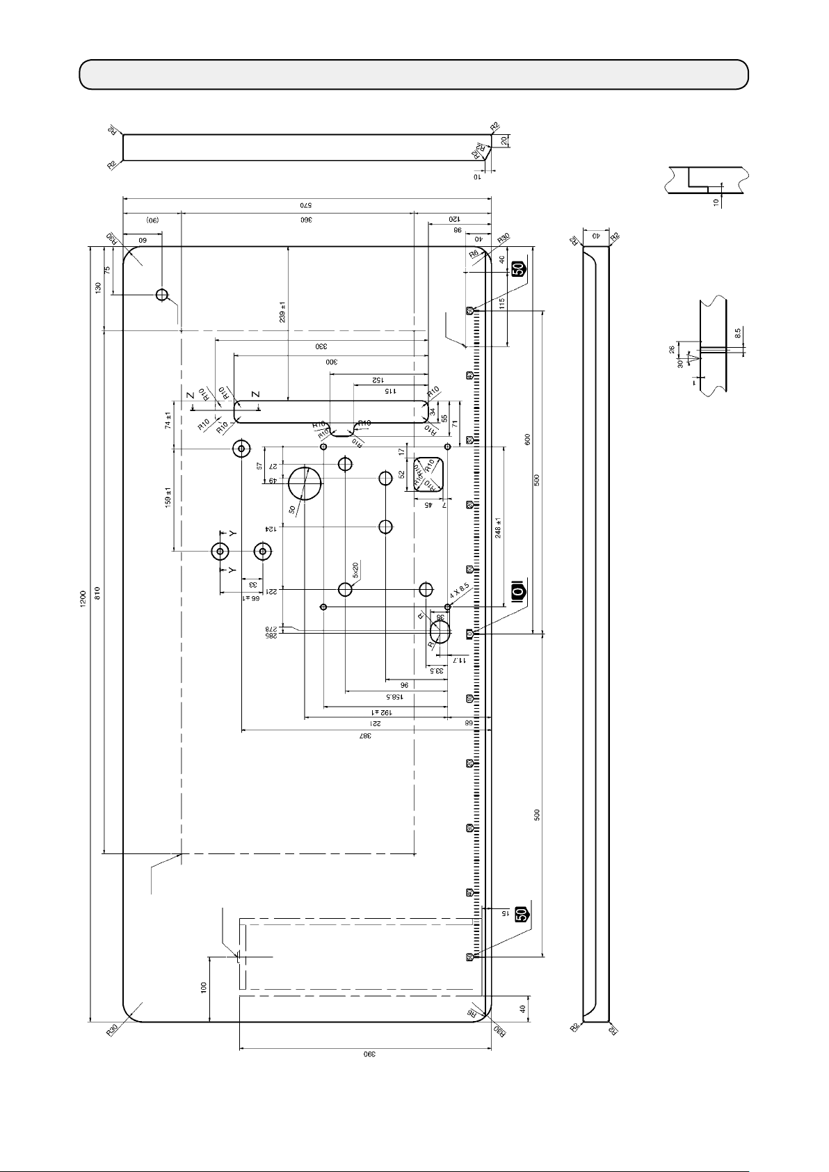
2. DRAWING OF TABLE (TABLE-FIXED TYPE / V-BELT TYPE)
Z-Z
C
D
(3 locations)
Y-Y
2 - ø 3.4 on the bottom surface, depth 10
D
(Drill a hole at the time of set-up.)
A
B
– 2 –
4 - ø 3.4 on the bottom surface, depth 20
Installing position of drawer stopper
A
(Drill a hole at the time of set-up.)
B
Drilled hole 17
(on the reverse side)
C
Page 5

3. DRAWING OF TABLE (TABLE-FIXED TYPE / DIRECT-DRIVE TYPE)
C
D
(3 locations)
Y-Y
A
B
2 - ø 3.4 on the bottom surface, depth 10
D
(Drill a hole at the time of set-up.)
4 - ø 3.4 on the bottom surface, depth 20
Installing position of drawer stopper
A
(Drill a hole at the time of set-up.)
B
Drilled hole 17
(on the reverse side)
C
– 3 –
Page 6

4. DRAWING OF TABLE (SEMI-SUBMERGED TYPE / V-BELT TYPE)
(4 locations)
Z-Z
C
(3 locations)
Y-Y
D
X-X
E
A
B
– 4 –
2 - ø 3.4 on the bottom surface, depth 10
4 - 10.5 hole, 26 hole facing depth 3.5
D
(Drill a hole at the time of set-up.)
E
4 - ø 3.4 on the bottom surface, depth 20
Installing position of drawer stopper
A
(Drill a hole at the time of set-up.)
B
Drilled hole 17
(on the reverse side)
C
Page 7

5. DRAWING OF TABLE (SEMI-SUBMERGED TYPE / DIRECT-DRIVE TYPE)
C
D
(4 locations)
Z-Z
A
E
B
2 - ø 3.4 on the bottom surface, depth 10
4 - 10.5 hole, 26 hole facing depth 3.5
D
(Drill a hole at the time of set-up.)
E
4 - ø 3.4 on the bottom surface, depth 20
Installing position of drawer stopper
A
(Drill a hole at the time of set-up.)
B
Drilled hole 17
(on the reverse side)
C
– 5 –
Page 8

6. THREADING THE MACHINE HEAD
WARNING :
To protect against possible personal injury due to abrupt start of the machine, be sure to start the follow-
ing work after turning the power off and ascertaining that the motor is at rest. If threading is wrong, stitch
skipping, thread breakage, needle breakage or irregular stitches will be caused. So, be careful.
[ Standard threading ]
Thread the machine head according to the following threading illustrations.
❶
❷
B
C
When covering thread is excessively loosened =
When covering thread is excessively loosened even
after passing B =
C
❸
❷
When using more stretchable
thread
When using less stretchable
thread
❶
D
B
When covering thread is excessively tense =
D
❸
Broken line E when using more stretchable thread
E
– 6 –
Page 9

7. ADJUSTING THE SILICON CONTAINER THREAD GUIDE
WARNING :
To protect against possible personal injury due to abrupt start of the machine, be sure to start the following
work after turning the power off and ascertaining that the motor is at rest.
29 mm
❹
10 mm
❶
❷
1) Loosen setscrews ❶. Adjust so that a distance of
10 mm is provided between the center of the upper
setscrew and top end ❹ of the base. Then, tighten
setscrews ❶.
2) Loosen setscrew ❷. Adjust so that a distance of 29
mm is provided between the center of setscrews ❶
and the center of medium needle thread guide bar.
After the adjustment, x the needle guide bars with
A B C
9 mm 15 mm 21 mm
3) Loosen setscrews ❸. Adjust the height of the
bottom end of hole in the respective needle thread
guide bars from the top end of base ❺ to the
distances as shown in the table above. After the
adjustment, x the needle thread guide bars with
setscrews ❸.
setscrew ❷.
8. ADJUSTING THE ROCKING THREAD TAKE-UP
❺
C
B
A
❸
WARNING :
To protect against possible personal injury due to abrupt start of the machine, be sure to start the following
work after turning the power off and ascertaining that the motor is at rest.
Adjust so that rocking thread take-up base ❶ is level
Horizontal
when the rocking thread take-up is in its lowest position.
Retighten screw ❷ to x the rocking thread take-up
❶
❷
base.
– 7 –
Page 10

9. ADJUSTING THE ROCKING THREAD TAKE-UP HOLDER
WARNING :
To protect against possible personal injury due to abrupt start of the machine, be sure to start the following
work after turning the power off and ascertaining that the motor is at rest.
1) Loosen setscrew ❶. Adjust so that the top end
of thread-hole ❺ in the rocking thread take-up is
aligned with the top end of rocking thread take-up
❹
❶
❺
1 mm
❻
❸
holder ❹ when rocking thread take-up ❸ is brought
to its lower end. After the adjustment, x the rocking
thread take-up holder with setscrew ❶.
2) Loosen setscrew ❷. Adjust so that a distance of
1 mm is provided between the top end of rocking
thread take-up ❸ and the top end of right needle
guard ❻ when rocking thread take-up ❸ is brought
to its lower end. After the adjustment, x the rocking
thread take-up holder with setscrew ❷.
❷
10. INSTALLING THE WASTE CLOTH PIPE
WARNING :
To protect against possible personal injury due to abrupt start of the machine, be sure to start the following
work after turning the power off and ascertaining that the motor is at rest.
❷
❸
❹
❶
1) Fix waste cloth pipe asm. ❶ with waste cloth pipe
setscrews ❷.
2) Insert waste cloth pipe ❸ into waste cloth pipe
asm. ❶, and x it with joint asm. ❹.
3) Connect the dust collection hose from the dust collection device to dust collection pipe asm. ❶. When
connecting it, use speed controller (accessories) ❺.
When installing waste cloth pipe ❸, install
it so as not to interfere with section A of
the upper knife holder.
A
❺
❸
– 8 –
Page 11

11. ADJUSTING THE UPPER KNIFE PRESSURE
WARNING :
To protect against possible personal injury due to abrupt start of the machine, be sure to start the following
work after turning the power off and ascertaining that the motor is at rest.
Standard adjustment position of thrust collars ❶ and ❷
is such that a clearance of 10 mm is provided between
them.
Place thrust collar ❶ between spring ❺ and lower knife
holder ❸. Press thrust collar ❶ against the end face of
lower knife holder ❸ and Fix thrust collar ❶, using setscrew ❹, with pressed against the end face of bushing ❸.
1) To increase the knife pressure
Move thrust collar ❷ to the left (in direction B).
Then, tighten setscrew ❻. Loosen setscrew ❹
of thrust collar ❶ once. Tighten setscrew ❹ to x
thrust collar ❶ with pressed against the end face of
bushing ❸ by the spring pressure.
2) To decrease the knife pressure
Move thrust collar ❷ to the right (in direction C).
Then, tighten setscrew ❻. Loosen setscrew ❹
of thrust collar ❶ once. Tighten setscrew ❹ to x
thrust collar ❶ with pressed against the end face of
bushing ❸ by the spring pressure.
* Standard assembly procedure of the thrust collar
for the MF-7900D-H24 :
Assemble the thrust collar, spring and thrust collar
in the written order.
❹
❸
❶
❺
10 mm
❷
❻
B
C
Set the knife pressure as low as possible
within the range where cloth is smoothly
cut for use.
12. ADJUSTING THE LATERAL POSITION OF THE LOWER KNIFE
WARNING :
To protect against possible personal injury due to abrupt start of the machine, be sure to start the following
work after turning the power off and ascertaining that the motor is at rest.
❸
❷
A
B
❹
❶
1) Loosen waste cloth pipe setscrews ❶.
2) Loosen lower knife holder setscrew ❷. Adjust the
lateral position of the lower knife by turning adjustment screw ❹ to move lower knife holder ❸ to the
right or left.
The lower knife moves to the left by turning the
adjustment screw in direction A.
The lower knife moves to the right by turning the
adjustment screw in direction B.
After the adjustment, tighten lower knife holder
setscrew ❷.
The tightening torque is 1.5 to 2 N・m (15 to 20
kgf・cm).
3) After the adjustment, x the lower knife holder with
the lower knife holder setscrew ❷.
4) Perform the adjustment of the position of waste
cloth pipe with waste cloth pipe setscrews ❶.
– 9 –
Page 12

13. ADJUSTMENT PROCEDURE OF ENGAGEMENT AMOUNT OF KNIVES
WARNING :
To protect against possible personal injury due to abrupt start of the machine, be sure to start the following
work after turning the power off and ascertaining that the motor is at rest.
1) Loosen upper knife holder setscrew ❸. Adjust so
❶
0.5 mm
that the top end of upper knife is located 0.5 mm
above lower knife ❷ when upper knife ❶ is brought
to its lower end.
2) After the adjustment, perform "11. ADJUSTING
THE UPPER KNIFE PRESSURE" p.9.
❷
❸
14. REPLACEMENT PROCEDURE OF UPPER KNIFE AND LOWER KNIFE
WARNING :
To protect against possible personal injury due to abrupt start of the machine, be sure to start the following
work after turning the power off and ascertaining that the motor is at rest.
1) Loosen setscrew ❶ in the joint asm., and remove
waste cloth pipe ❷.
❷
❶
2) Loosen setscrews . In this state, loosen lower
knife retaining plate setscrew ❸. Pull out lower
❸
❽
knife ❺ in direction B while pulling upper knife holder ❽ in direction A .
3) Insert a new lower knife in the groove of lower knife
holder ❻, and tighten setscrew ❸ in the lower knife
A
presser plate in the state that the blade point is
aligned with the top surface of the throat plate.
❽
❹
❺
❻
B
4) When replacing the upper knife, loosen setscrew ❼
in the upper knife holder, remove upper knife holder
❽, loosen setscrew ❾ in the upper knife, and remove upper knife .
5)
Fix new upper knife with setscrew ❾ in the upper knife.
6)
❾
After replacing the upper knife, align the left end face of
upper knife holder ❽ and the left end face of knife shaft
❹, and tighten setscrew ❼ in the upper knife holder.
7) After replacing the upper knife, perform "11. AD-
❼
JUSTING THE UPPER KNIFE PRESSURE" p.9
and
"13. ADJUSTMENT PROCEDURE OF EN-
GAGEMENT AMOUNT OF KNIVES" p.10.
– 10 –
Page 13

15. ADJUSTING THE UPPER KNIFE STROKE
WARNING :
To protect against possible personal injury due to abrupt start of the machine, be sure to start the following
work after turning the power off and ascertaining that the motor is at rest.
1) Loosen setscrews ❶ in the waste cloth pipe and
❶
❷
2) Remove setscrews ❸ in the installing base cover,
remove waste cloth pipe ❷.
and remove installing base cover ❹.
❻
❸
❹
❼
❺
B A
3) Loosen lock nut ❺ of the adjustment pin and move
adjustment pin ❻ up or down to adjust the stroke of
the upper knife.
4) The standard adjustment position is the position
where the engraved marker dot A of adjustment
lever ❼ aligns with the engraved marker line B of
adjustment pin ❻. Loosen nut ❺ and raise adjustment pin ❻ to increase the stroke of the upper
knife, and lower it to decrease the stroke. After the
adjustment, perform "13. ADJUSTMENT PROCE-
DURE OF ENGAGEMENT AMOUNT OF KNIVES"
p.10.
– 11 –
 Loading...