

JUKI MF-7800D Series Engineer's Manual
40084355
No.E387-00
ENGINEER’S MANUAL
Semi-dry head, Cylinder-bed Top and Bottom Coverstitch Machine
MF-7800D Series
®

PREFACE
This Engineer’s Manual is written for the technical personnel who are responsible for the service and maintenance
of the machine.
The Instruction Manual for these machines intended for the maintenance personnel and operators at an apparel
factory contains operating instructions in detail. And this manual describes "Standard Adjustment", "Adjustment
Procedures", "Results of Improper Adjustment", and other important information which are not covered by the
Instruction Manual.
It is advisable to use the relevant Instruction Manual and Parts List together with this Engineer’s Manual as well as
the MF-7800, SC-500, and SC-510 Series Manuals when carrying out the maintenance of these machines.
In addition, for the motor for the sewing machine with thread trimmer, refer to the separate Instruction Manual or
Engineer’s Manual for the motor. And for the control panel, refer to the Instruction Manual for the control panel.
This manual gives the "Standard Adjustment" on the former page under which the most basic adjustment value is
described, and on the latter page "Results of Improper Adjustment" under which stitching errors and troubles arising
from mechanical failures are described together with the "Adjustment Procedures".

CONTENTS
1. SPECIFICATIONS................................................................................................... 1
2. CONFIGURATION OF THE MACHINE COMPONENTS........................................ 2
3. MODEL NUMBERING SYSTEM ............................................................................ 3
(1) MF-7800D Series . ................................................................................................................... 3
(2) MF-7800D Series Thread trimmer.......................................................................................... 4
4. MOTOR PULLEY AND BELT ................................................................................. 5
5. ST ANDARD ADJUSTMENT ................................................................................... 6
(1) Threading the machine head . ............................................................................................... 6
(2) Adjusting the rocking thread take-up ................................................................................... 8
(3) Adjusting the position of the needle thread guide rod ..................................................... 10
(4) Adjusting the position of the thread receiver .................................................................... 12
(5) Adjusting the position of the spreader thread guide and spreader thread take-up....... 14
(6) Adjusting the spreader......................................................................................................... 16
(7) Adjusting the timing relation between the looper and needle bar................................... 20
(8) Returning amount of the looper .......................................................................................... 22
(9) Height of the needle ............................................................................................................. 24
(10)Locus and longitudinal motion of the looper..................................................................... 26
(11)Adjusting the needle guard ................................................................................................. 28
(12)Adjusting the feed dog ......................................................................................................... 32
(13)Adjusting the feed relation .................................................................................................. 38
(14)Adjusting the presser foot ................................................................................................... 40
(15)Adjusting the micro-lifter ..................................................................................................... 42
(16)Adjusting the looper thread cam......................................................................................... 44
(17)With regard to lubrication .................................................................................................... 46
(18)Adjusting and setting SC-510 .............................................................................................. 50
(19)MF-7700D/MF-7800D How to use the timing gauge ........................................................... 54
(20)MF-7800D-H21 ....................................................................................................................... 55
(21)MF-7800D-E10 ....................................................................................................................... 63
(22)MF-7800D-UT25/UT24 ........................................................................................................... 81
(23)MF-7800D-UT22 ....................................................................................................................111
(24)MC-35/MC-36 ....................................................................................................................... 121
(25)PL11 ..................................................................................................................................... 131
6. OTHER CAUTIONS ............................................................................................ 140
(1) MF-7800D dry section......................................................................................................... 140
(2) Application of appropriate grease .................................................................................... 140
(3) Adhesives application spots ............................................................................................. 142
7. TROUBLES AND CORRECTIVE MEASURES .................................................. 143

8. DRAWING OF TABLE......................................................................................... 157
(1) Top mount type ................................................................................................................... 157
(2) Half-sunk table .................................................................................................................... 158
(3) Table for H21 ....................................................................................................................... 159
(4) Table for 7800D-E10............................................................................................................ 160

– 1 –
1. SPECIFICATIONS
No. Item Specifications
1Model name Semi-dry head, cylinder-bed top and bottom coverstitch machine
2 Model MF-7800D series
3Stitch type ISO standard 406, 407, 602, and 605
4 Example of application Hemming and covering for knits and general knitted fabrics
5Max. sewing speed 4,000 sti/min (at the time of intermittent operation)
3-needle...........5.6 mm, 6.4 mm
2-needle...........4.0 mm, 4.8 mm
1 : 0.9 to 1 : 1.8 (stitch length : less than 2.5 mm)
7 Differential feed ratio Micro-differential feed adjustment mechanism is provided.
(Micro-adjustment)
8 Stitch length 0.9 mm to 3.6 mm (can be adjusted up to 4.5 mm)
UY128GAS #9S to #12S (standard #10S)
(Nm65 to Nm80, standard Nm70)
10 Needle bar stroke 31 mm
11 Dimensions Height: 450 mm, Width: 456 mm, Length: 267 mm
12 Weight 42 kg, 44 kg (with UT25), 48 kg (with UT22)
5 mm (with top covering)
8 mm (without top covering)
Main feed ................ dial type stitch pitch adjustment method
14 Feed adjustment method Differential feed....... lever adjustment method (micro-adjustment
mechanism is provided.)
15 Looper mechanism Spherical rod drive method
16 Lubricating system Forced lubrication method by gear pump
17 Lubricating oil JUKI MACHINE OIL 18 (Equivalent to ISO VG18)
18 Oil reservoir capacity Oil gauge lower line : 600 cm3 to upper line : 900 cm
3
19 Installation Top mount type, Semi-submerged type
20 Micro-lifter Provided as standard
21 Provided as standard
22 Cartridge oil filter Provided as standard
6Needle gauge
9 Needle
13 Lift of presser foot
Needle tip, needle thread silicone tank
– 2 –
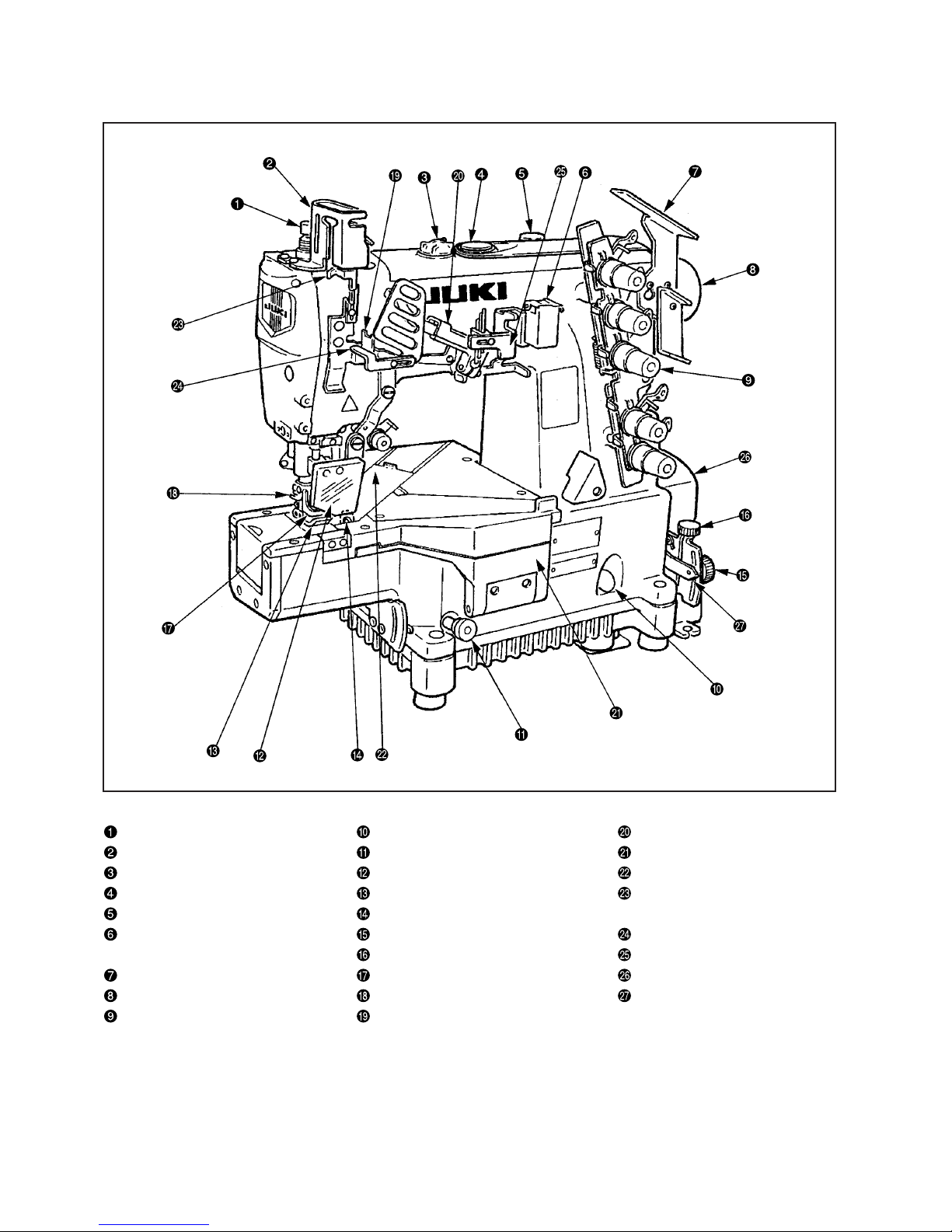
2. CONFIGURATION OF THE MACHINE COMPONENTS
Presser spring regulator Oil gauge Rocking thread take-up
Needle bar thread take-up cover Feed regulating knob Front cover
Oil circulation identification window Eye guard cover Slide cover
Oil hole cap Throat plate Needle bar thread take-up thread
Micro-lifter Needle tip silicon oil lubricating unit receiver
Needle thread silicon oil Differential lock nut
Rocking thread take-up thread guide
lubricating unit Micro-adjustment knob Silicon container thread guide
Thread guide No. 1 Finger guard Belt cover
Upper pulley Thread trimming knife Differential feed regulating lever
Thread tension nut Rocking thread take-up receiver

– 3 –
1234567891011121314 15 16 17 18 19 20 21
MF78 D –
3 to 6 Model code
7822 2-needle top & bottom covering stitch
7823 3-needle top & bottom covering stitch
8 to 10 Application code
Application Description
U10 For universal Lapseam, Covering, Hemming
K10 For covering Flatting-out
H21 For Hemming With left hand fabric trimmer
E10 For elastic band attaching With left hand fabric trimmer/tension roller
C10 For collarette For regular binder
12 to 13 Needle gauge
40 4.0 mm
56 5.6mm
64 6.4 mm
*In case of 3-needle, it is not possible to select 40.
11 Tongue shape of throat plate
BStandard
D D-type
14 to 17 Device and attachment
MC36 Pneumatic dust collection unit (mechanical valve type)
21 Classification of table specifications
1 Desktop
2 Semi-submerged
3. MODEL NUMBERING SYSTEM
(1) MF-7800D Series
Semi-dry head, cylinder-bed top and bottom coverstitch machine
Applicable model : MF-7800D Series
19 Specification Code for Destination
A Standard
G For China (domestic China)
H For Turkey
*1 (desk top) only for E10
20 Accessory Specification Code
A
G
Standard (Foreign language manuals in Japanese, English,
Chinese, German, French, Italy, Turkey, and Spanish)
Chinese (available only in China) (2-language manual in
English and Chinese)
– 4 –
Semi-dry head, cylinder-bed top and bottom coverstitch machine
Applicable model : MF-7800D Series Thread trimmer
(2) MF-7800D Series Thread trimmer
8 to 10 Application code
Application Description
U10 For universal Lapseam, Covering, Hemming
K10 For covering Flatting-out
H21 For Hemming With left hand fabric trimmer
E10 For elastic band attaching
With right hand fabric trimmer/tension roller
123456789101112131415161718192021222324252627282930
MF78 D –
14 to 25 Device and attachment
UT22 Solenoid type vertical thread trimmer unit
UT24 Pneumatic blow bobbin thread trimmer unit
UT25 Pneumatic vertical thread trimmer unit
MC35 Pneumatic dust collection unit (solenoid type)
PL11 Cloth flat rollers
3 to 6 Model code
7822 2-needle top & bottom covering stitch
7823 3-needle top & bottom covering stitch
7813 3-needle one-side covering stitch
12 to 13 Needle gauge
40 4.0mm
56 5.6mm
64 6.4mm
* In case of 3-needle, it is not possible to select 48.
11 Tongue shape of throat plate
B Standard
D D-type
27 Specification Code for Destination
A Standard
G For China (domestic China)
H For Turkey
30 Classification of table specifications
1 Desktop
2 Semi-submerged
28 Accessory Specification Code
A
G
Standard (Foreign language manuals in Japanese, English,
Chinese, German, French, Italy, Turkey, and Spanish)
Chinese (available only in China) (2-language manual in
English and Chinese)
29 Control box and motor classification
B SC-500/M50
C SC-510/M51

– 5 –
4. MOTOR PULLEY AND BELT
MF-7800D Series
50Hz 60Hz
(sti/min) Pulley size (mm) Belt size (inch) Pulley size (mm) Belt size (inch)
3,500 ø80 M-38 ø65 M-37
4,000 ø90 M-38 ø75 M-37
1 . The table shows the numbers when a 3-phase 2-pole 400 W clutch motor (1/2 HP) is used.
2 . The commercially-available motor pulley near to the counted value is designated since the outside diameter of
the commercially-available motor pulley counts by 5 mm.
3 . When you use a new sewing machine, use the machine at a speed of 4,000 sti/min or less for the first 200 hours
(approximately one month). A good result can be obtained in terms of the durability.
(Caution) 1. Use a motor pulley which is adaptable to this sewing machine.
2. This sewing machine will exceed its max. revolutions and max. sewing speed, finally leading
to the occurrence of malfunction, unless the adaptable motor pulley is used.
Sewing speed of the
machine
– 6 –
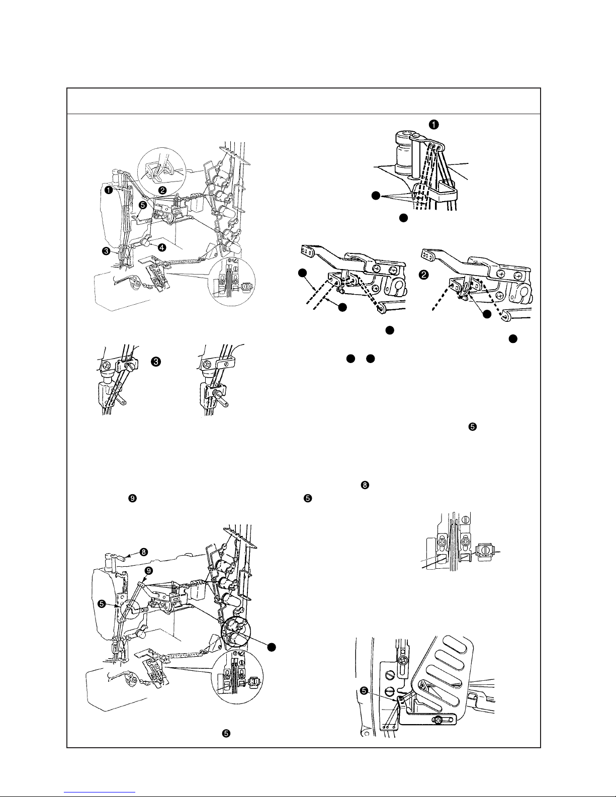
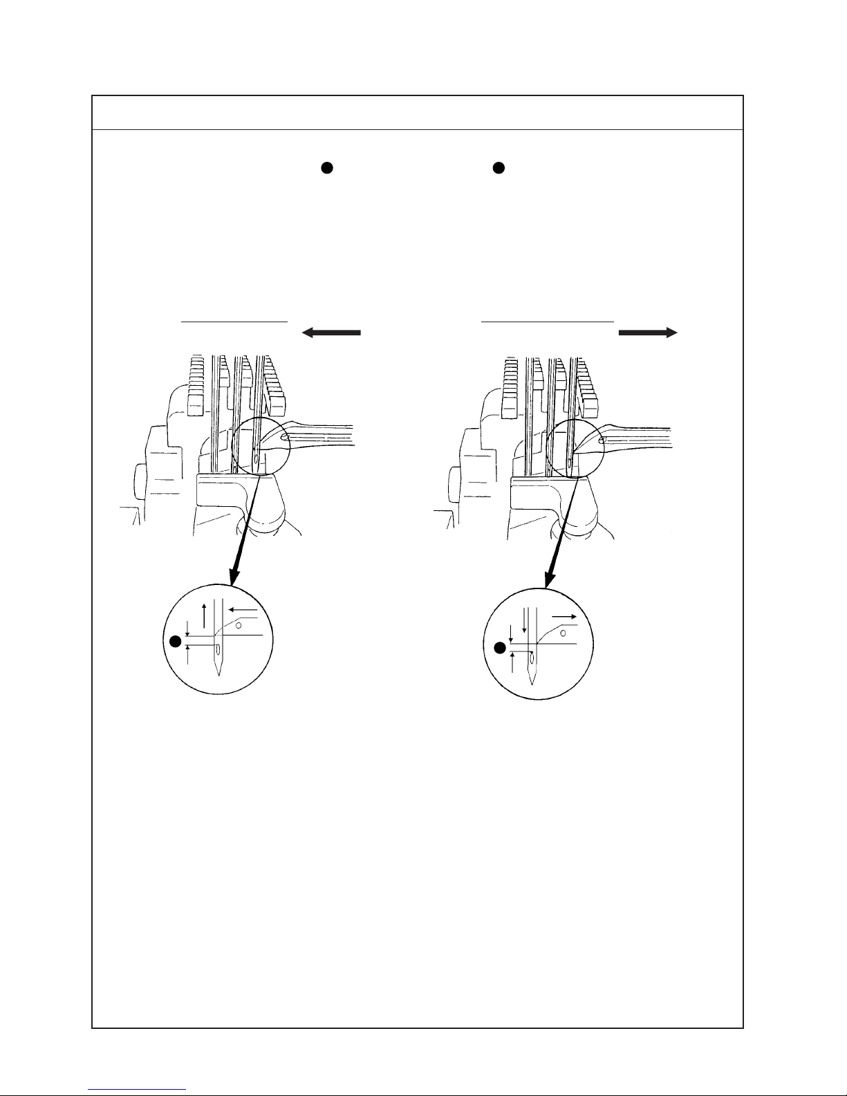
(Caution) In case of threading for standard seams, rocking thread take-up thread guide is not used.
2. Threading for soft seams
(1) When soft seams are required, change the threading of needle thread and slide the position of looper thread
cam eyelet.
(2) Do not pass needle thread through needle bar thread take-up . Pass the thread from rocking thread
take-up to rocking thread take-up thread guide .
(3) Other points are same as those of "1. Threading for standard seam".
1. Threading for standard seam
A
Broken lines A when stretcher thread is used
C
B
D
When covering thread is
excessively loosened =
B
When covering thread is
excessively loosened even
after passing
B
=
C
When covering thread is
excessively tense =
D
When using more
stretchable thread
When using less
stretchable thread
1. Adjust the bottom end of left-hand thread guide
to the engraved marker line on the front side.
2. Adjust the position of the hole of right-hand
thread guide to the left.
Standard Adjustment
5. ST ANDARD ADJUSTMENT
(1) Threading the machine head
(Caution) In case of the soft seams, rocking thread
take-up thread guide is used.
E
In case of soft seams
Engraved marker line
Right
Left
– 7 –
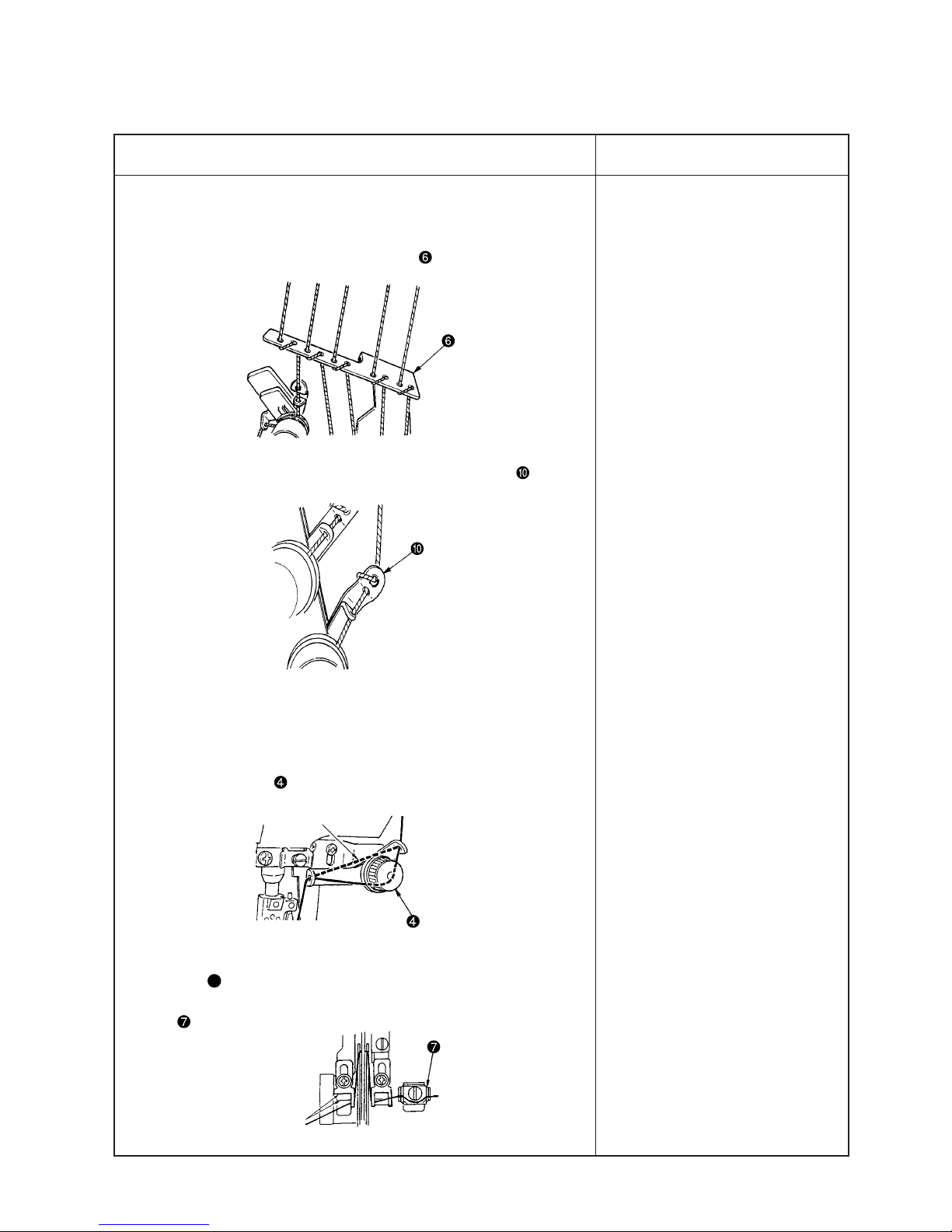
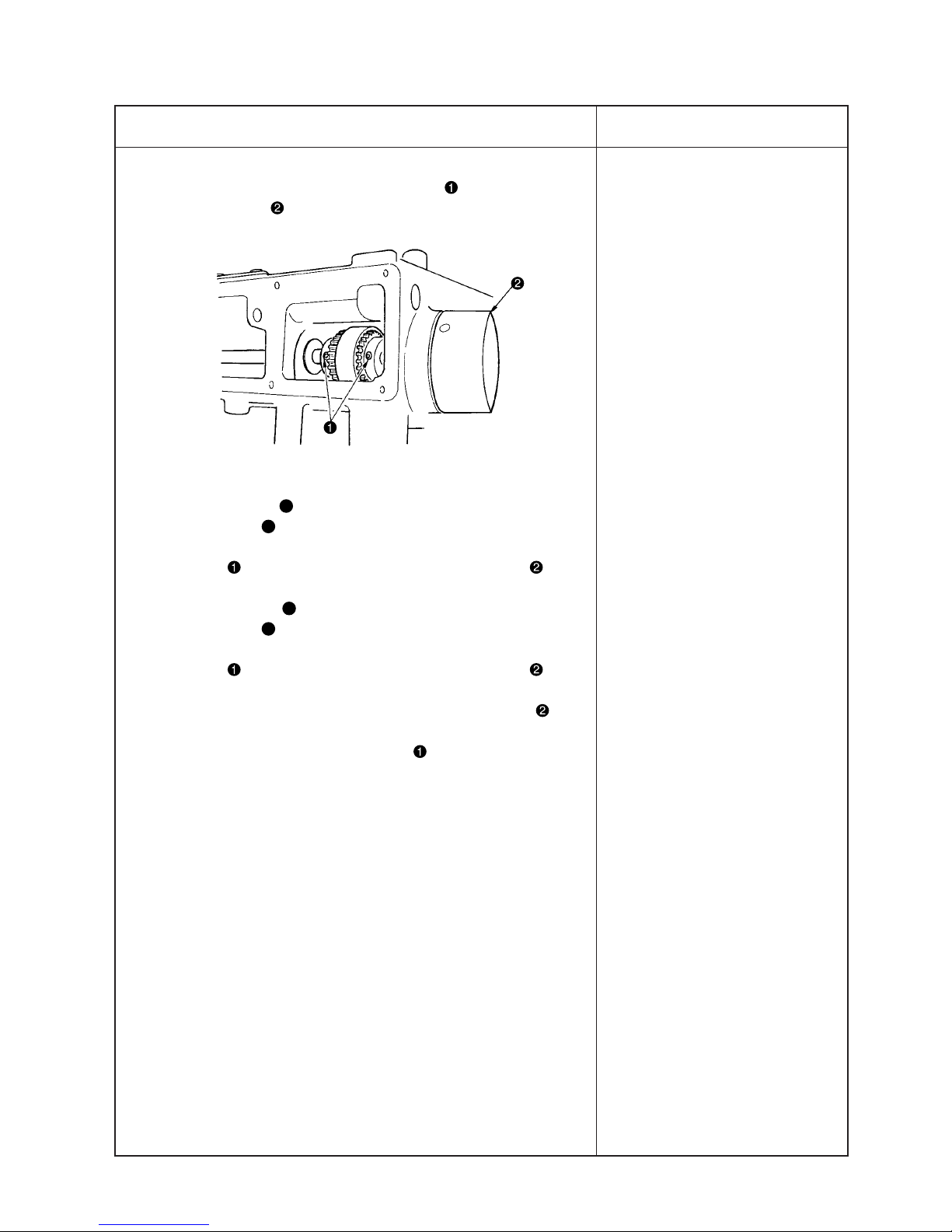
1. When motion of thread is very rough, and stable seams can not be
obtained, there are cases where the condition can be improved by
the following threading.
(1) Wind thread around 1st thread guide .
(2) Wind thread around the thread tension thread guide .
2. When using more stretchable thread (wooly thread or the like), the
threading as given below does not make thread stretch and neat
seams can be obtained.
(1) Do not pass thread (for spreader) through spreader auxiliary
thread tension .
(2) Do not pass thread (for spreader) through the thread tension
disk E.
(3) Do not pass thread through the looper thread small tension disk
.
o When threading is not properly
performed, not only sewing
trouble occurs, but also needle
breakage is caused. So, be
careful.
Adjustment Procedure
Results of Improper Adjustment
Do not pass thread.
Engraved marker line
– 8 –
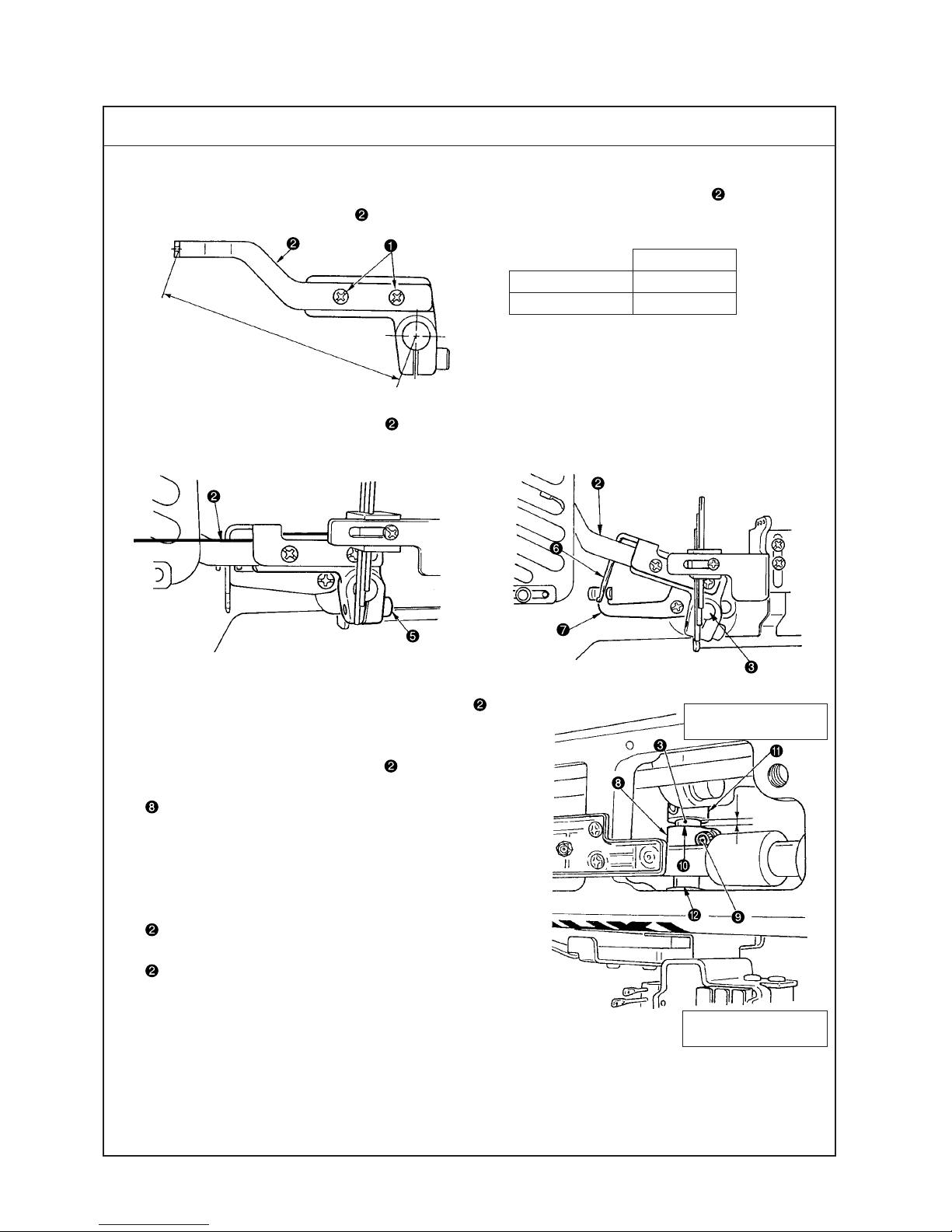
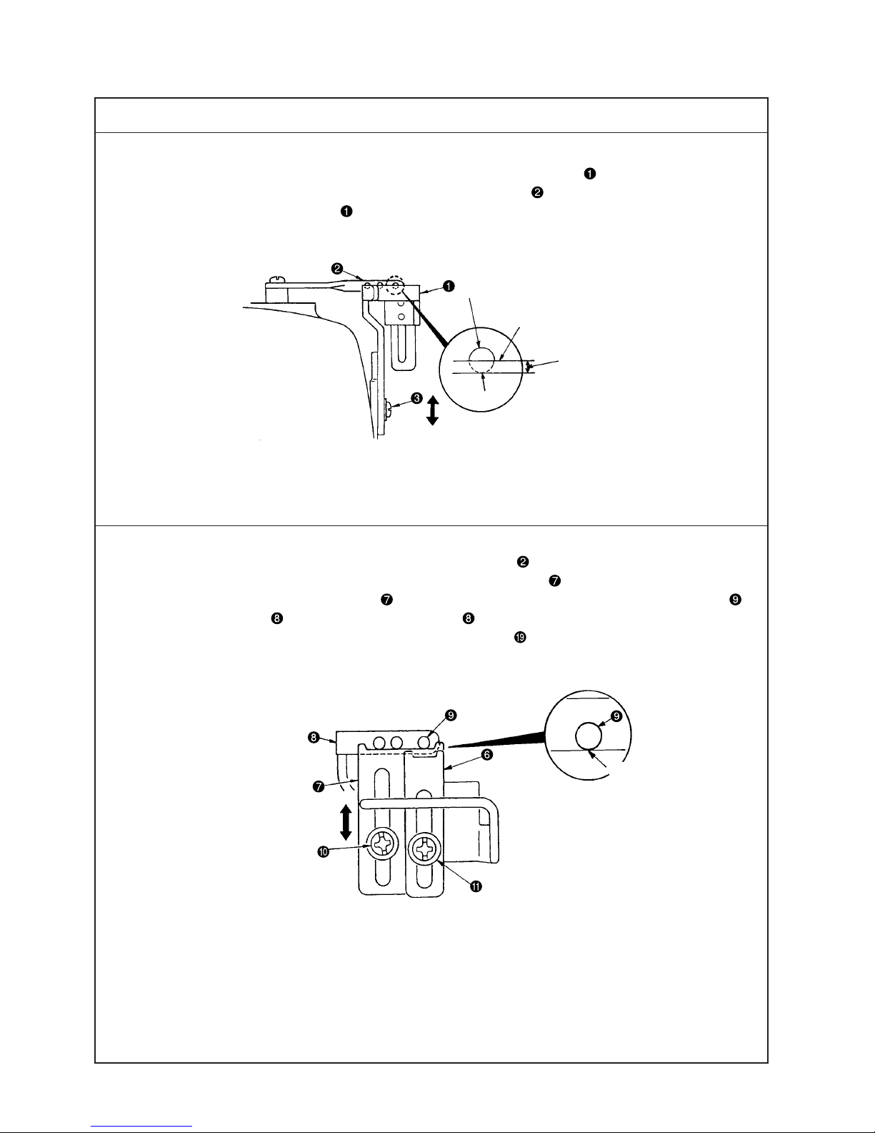
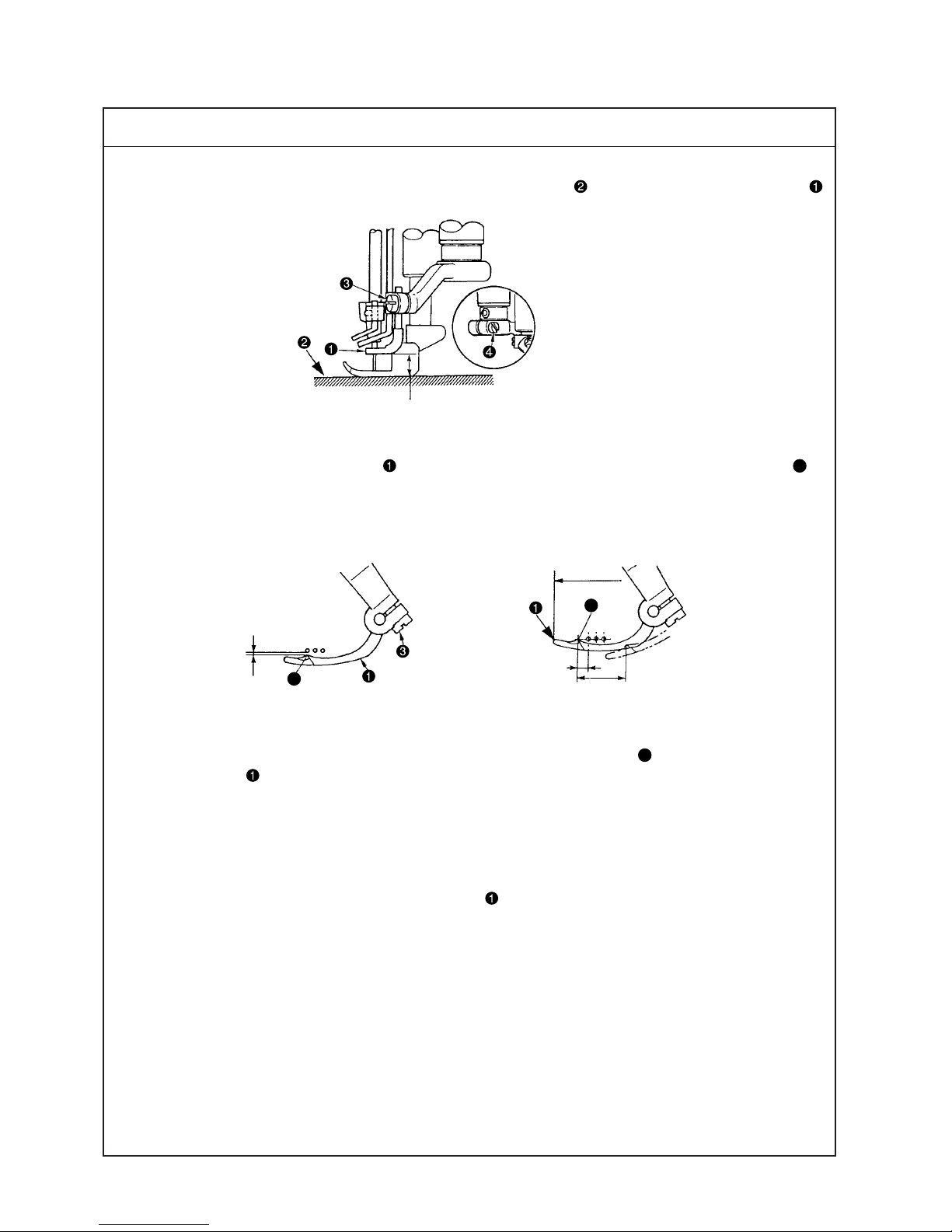
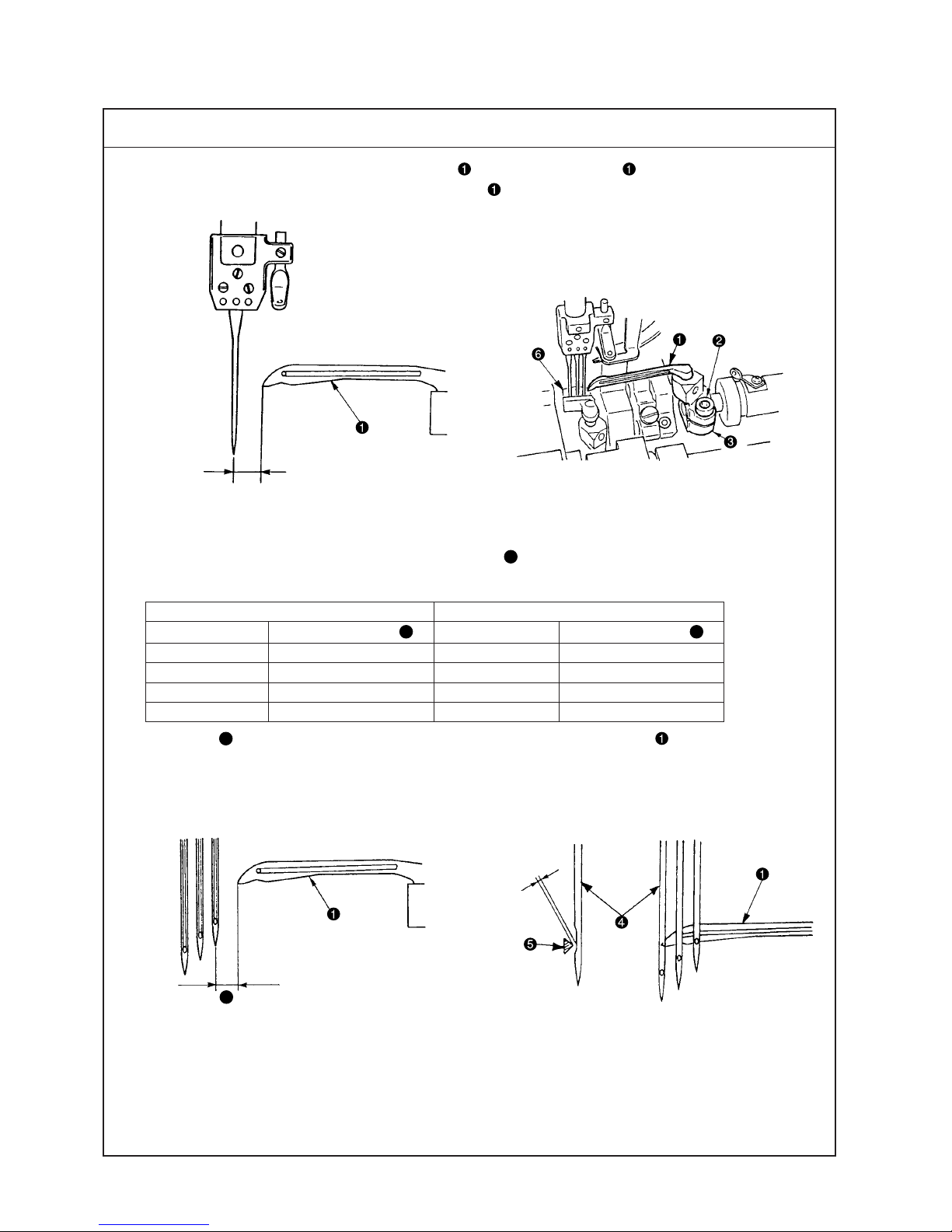
(2) Adjusting the rocking thread take-up
1. Length of the rocking thread take-up
(1) Dimension A from the center of the shaft to the thread hole face of rocking thread take-up is the standard
length of rocking thread take-up .
2. Position of the rocking thread take-up
(1) Install so that rocking thread take-up is flush when the needle bar is in its lowest position.
3. Timing of the rocking thread take-up
(1) It is the standard timing that rocking thread take-up is in
its lowest position as well when the needle bar is in its lowest
position.
Timing of rocking thread take-up is performed by
adjusting the position of rocking thread take-up ball arm
.
4. Relation between the timing of rocking thread take-up and
the needle thread loop
(1) When using the excessively stretchable thread or the hard-
to-stretch thread, the size of needle thread loop can be
changed by changing the timing of rocking thread take-up
.
(2) Relation between the timing of the rocking thread take-up
and the size of needle thread loop is as shown in the
table on the next page.
(The relation becomes reverse when using the needle bar
thread take-up = standard seams and when it is not used =
soft seams. So, be careful.)
A
4mm
A
Standard Adjustment
↑
Anti-operator’s side
Operator’s side
↓
Dimension A
Standard seams 90
Soft seams 98
Unit : mm
Flush
– 9 –
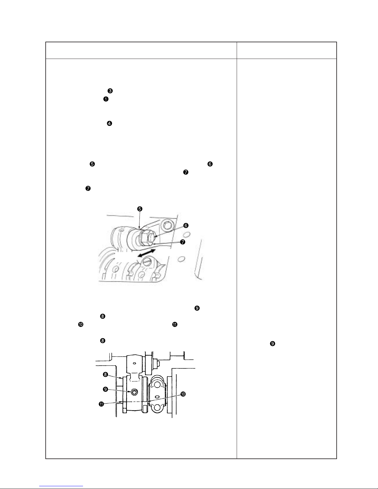
1. Length of the rocking thread take-up
(1) Loosen screws and move rocking thread take-up to the right
or left to adjust the length.
2. Position of the rocking thread take-up
(1) Loosen screw and move rocking thread take-up up or down
to adjust the position.
(Caution) When adjusting the position of rocking thread take-up
, fix the rocking thread take-up with setscrew in
the rocking thread take-up so that spreader thread takeup and spreader thread guide do not come in
contact with each other.
3. To adjust the timing of the rocking thread take-up , remove the
top cover, loosen setscrew in the rocking thread take-up ball arm
and move the position of rocking thread take-up ball arm to and
fro.
(1) Standard adjustment figure is the position where the rear end (anti-
operator’s side) of rocking thread take-up ball arm aligns with
engraved marker line on rocking thread take-up shaft . (As the
standard at this time, note that the clearance provided between the
rear end of rocking thread take-up ball arm and thrust collar is
4 mm.)
(Caution) 1. When loosening screw in rocking thread take-up
ball arm , there is a case where rocking thread takeup rotates by its weight. After the adjustment, be
sure to check the rocking position (flush at the lowest
position) of rocking thread take-up .
2. When moving rocking thread take-up ball arm to
the operator’s side, adjust rocking thread take-up ball
arm within the range where it does not come in
contact with rocking thread take-up bushing
(operator’s side).
o When length of rocking thread
take-up is lengthened, needle
thread is tightened.
(Caution) When lengthening
rocking thread take-up
, check whether it
comes in contact with
the thread take-up
cover.
o When length of rocking thread
take-up is shortened, needle
thread is loosened.
o When installing position of
rocking thread take-up is
raised, needle thread is loosened
when the needle bar thread takeup is used, and needle thread is
tightened when the needle bar
thread take-up is not used.
Adjustment Procedure
Results of Improper Adjustment
Delay timing Advance timing
(Move to operator’s side.) (Move to anti-operator’s side.)
When needle bar thread take-up is used Loop becomes small. Loop becomes large.
When needle bar thread take-up is not used Loop becomes large. Loop becomes small.
4. Relation between timing of rocking thread take-up and needle thread loop
Adjusting procedure is the same as step 3. Loosen setscrew in rocking thread take-up ball arm and
adjust the position of rocking thread take-up ball arm .
(Caution) Adjust the timing of rocking thread take-up each time in accordance with thread used
or conditions.
– 10 –
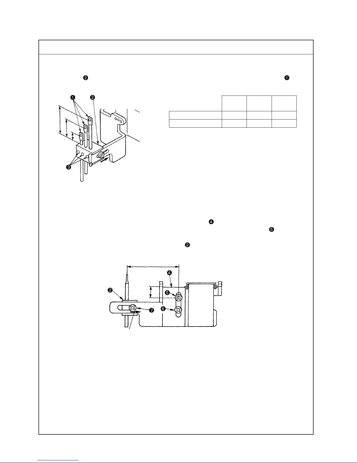
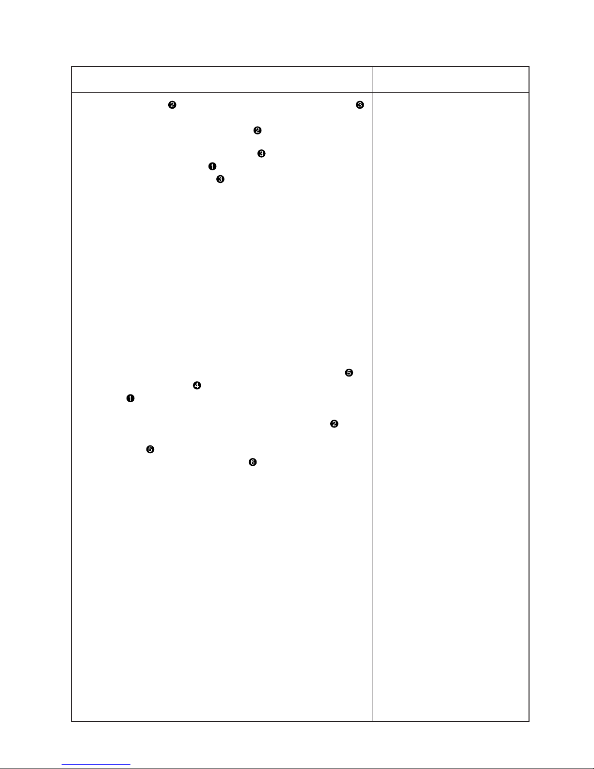
(3) Adjusting the position of the needle thread guide rod
1. Position of the needle thread guide rod
(1) Dimensions of left needle A, middle needle B and right needle C from the top surface of needle thread
guide base to the bottom ends of holes are the standard height of needle thread guide rods .
2. Adjusting the position of needle thread guide base and silicon container thread guide
(1) It is the standard that the height of silicon container thread guide (refer to 2. CONFIGURATION OF THE
MACHINE COMPONENTS) is the position where the height from the center of setscrew to the bottom
end of thread hole is 9 mm.
(2) Move the lateral position of needle thread guide base fully to the right of slot (43 mm).
Extreme right position
43mm
9mm
Left Middle Right
needle A needle B needle C
Standard seams 13 16 19
Soft seams 15 13 11
Unit : mm
Standard Adjustment
C
B
A
Extreme right position
– 11 –
1. Loosen setscrews , adjust the height of respective needle thread
guide rods , and fix the rods with setscrews .
(Caution) 1. Move the lateral position of needle thread guide base
fully to the right of slot.
2. When adjusting the height of needle thread guide rods
, install the rods so that the thread holes are parallel
to the thread holes of silicon container thread guide
so that excessive resistance is not applied to
threads.
2. Adjusting the position of needle thread guide base and silicon
container thread guide
(1) Loosen setscrews and and move silicon container thread guide
up or down to adjust the height.
(2) Loosen setscrew and adjust the lateral position of needle thread
guide base .
o When needle thread guide rod
is raised, needle thread is
loosened.
o When needle thread guide rod
is lowered, needle thread is
tightened.
oWhen silicon container thread
guide is raised, needle thread
is loosened.
o When silicon container thread
guide is lowered, needle
thread is tightened.
o When needle thread guide base
is moved to the left, needle
thread is loosened.
Adjustment Procedure
Results of Improper Adjustment
– 12 –
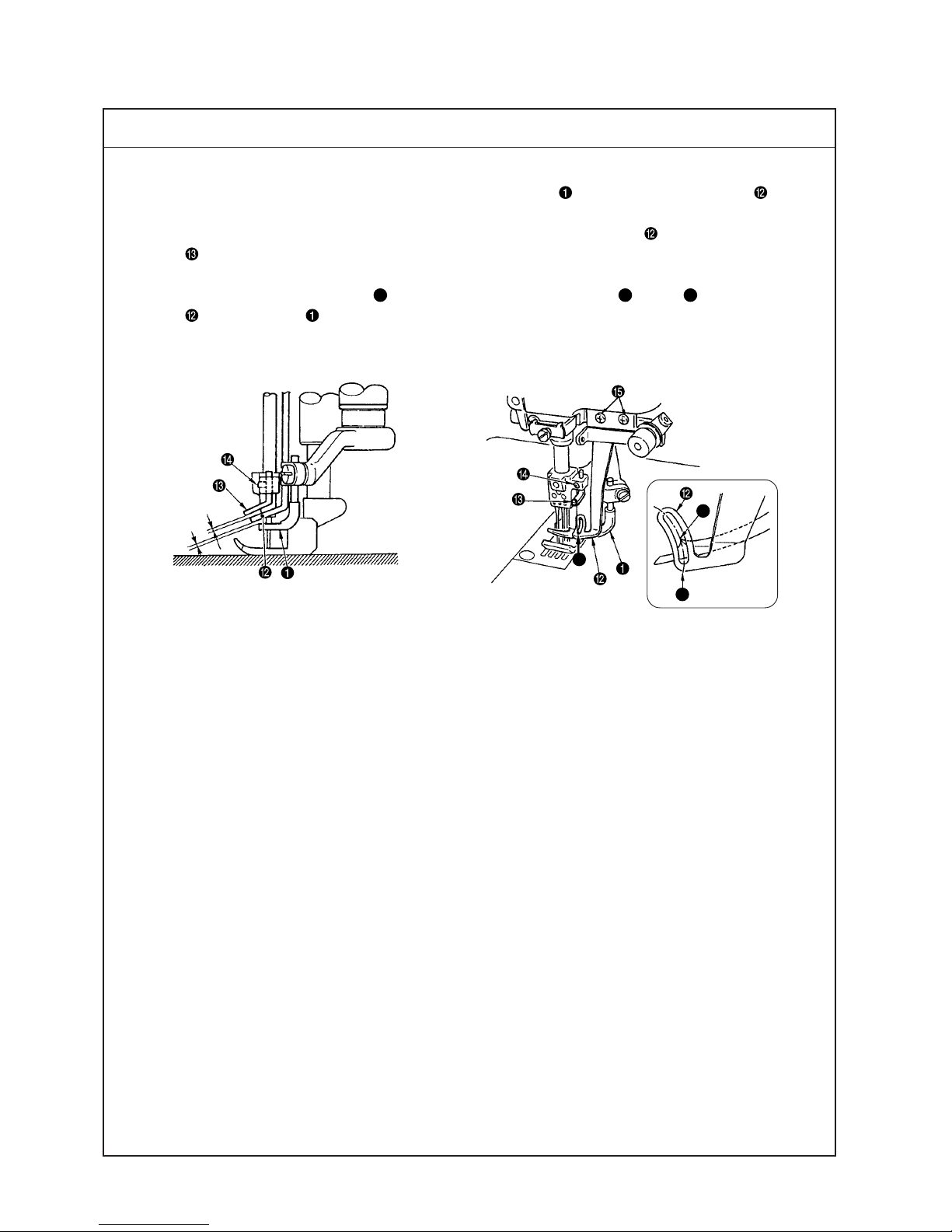
(4) Adjusting the position of the thread receiver
1. Position of the needle bar thread take-up thread receiver (in case of standard seams)
(1) It is the standard that the height of needle bar thread take-up thread receiver is in the position where the
bottom end of thread hole to the center of needle bar thread take-up aligns with the top surface of needle
bar thread take-up thread receiver when the needle bar is in its lowest position.
Standard Adjustment
Thread hole
Center of hole
This range
To align
1. Position of the rocking thread take-up thread receiver (in case of soft seams)
(In case thread is not passed through needle bar thread take-up )
(1) It is the standard that the height of rocking thread take-up receiver is in the position where the top
surface of rocking thread take-up receiver is in the range of the center to the top end of thread hole of
rocking thread take-up when rocking thread take-up is in its lowest position.
(For the details of the position of the illustration below, refer to Rocking thread take-up receiver of 2.
CONFIGURATION OF THE MACHINE COMPONENTS.)
To align

– 13 –
1. Loosen setscrew and move needle bar thread take-up thread
receiver up or down to adjust the height.
2. When desired to make needle bar thread take-up thread receiver
work especially on the right needle where loop is hard to be made,
adjust the height of right needle thread receiver with setscrew .
1. Loosen setscrew and move rocking thread take-up receiver
up or down to adjust the height.
2. When desired to make rocking thread take-up receiver work
especially on the right needle where loop is hard to be made, adjust
the height of the right needle thread receiver with screw .
o When the needle bar thread
take-up thread receiver is
raised, loop becomes large.
o When the needle bar thread
take-up thread receiver is
excessively raised.
Adjustment Procedure
Results of Improper Adjustment
– 14 –
(5) Adjusting the position of the spreader thread guide and spreader thread take-up
1. Relation of the position between spreader thread take-up and spreader thread guide is the standard
when the top end of thread hole of spreader thread guide aligns with the bottom end of slot of
spreader thread take-up when spreader thread take-up is in its highest position.
Adjust the relation of the position so that thread is moderately stretched when spreader thread take-up
is in its highest position in accordance with thread used or conditions.
2. Standard position of the spreader auxiliary thread tension
Standard adjustment figure of the spreader auxiliary thread tension is the standard when the top end of
thread tension rod is flush with knob .
A
Standard Adjustment
Highest position
To align
– 15 –
1. Loosen setscrews in spreader thread guide and adjust the
position of spreader thread guide . (Spreader thread take-up
is fixed to rocking thread take-up and can not be adjusted in the
height direction.)
2. After the adjustment, turn the sewing machine by hand and check
whether spreader thread take-up comes in contact with spreader
thread guide , or section A of clearance is too small.
3. Adjusting procedure of the clearance
(1) Loosen setscrews in spreader thread guide and adjust in the
lateral direction, or loosen setscrews in the rocking thread takeup and move spreader thread take-up to the right or left to adjust
the clearance.
(Caution) When loosening setscrews in the rocking thread take-
up and adjusting the position of spreader thread takeup , adjust so that 95, length of rocking thread takeup does not change.
o When the relation of position
between spreader thread takeup and the spreader thread
guide is not proper, sewing
troubles such as stitch skipping
and the like will be caused.
o If thread is less stretched and
slackness of thread occurs at the
thread take-up section when
spreader thread take-up is in
its highest position, the spreader
fails to pick up thread and stitch
skipping occurs.
o If stretch or feeding of thread is
excessive when spreader thread
take-up is in its highest
position, not only thread on the
seam side is drawn and needle
thread can not be tightened, but
also needle bend or needle
breakage will be caused.
o If stretch or feeding of thread is
excessive when spreader thread
take-up is in its lowest
position, thread slacks when the
spreader moves from left to right
and stitch skipping occurs.
Adjustment Procedure
Results of Improper Adjustment
– 16 –
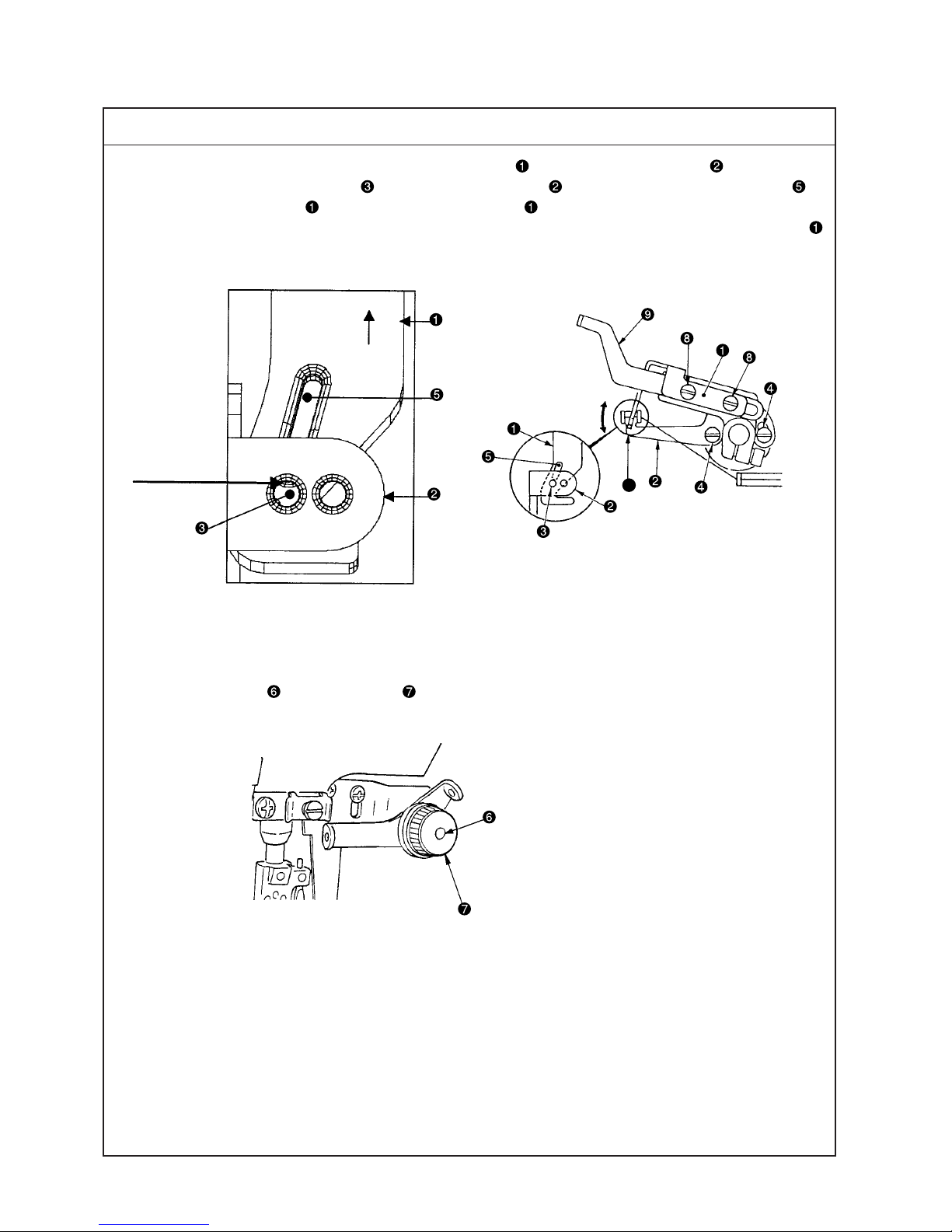
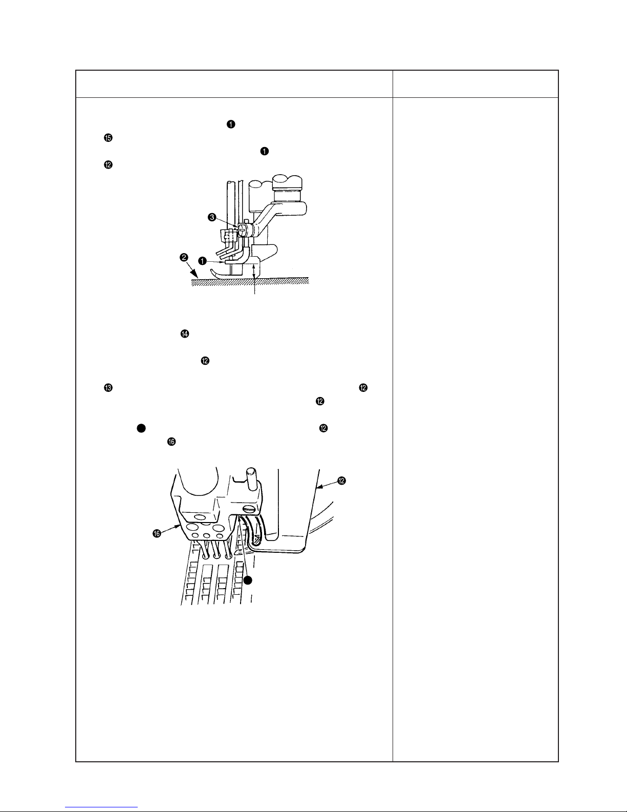
(6) Adjusting the spreader
1. Height of the spreader
It is the standard that the height from the top surface of throat plate to the bottom surface of spreader
is 7.8 to 8.2 mm.
7.8 to 8.2mm
0.1 to 0.3mm
A
Standard Adjustment
2. Longitudinal position of the spreader
It is the standard that when spreader returns from the extreme left position to the right and top end A of
thread hooking section reaches to the front of left needle, the clearance between the spreader and the left
needle is 0.1 to 0.3 mm.
3. Protruding amount
It is the standard that the dimension from the center of left needle to top end A of thread hooking section,
when spreader is in the extreme left position, is 4.5 to 5.5 mm.
4. Spreader stroke
It is the standard that the spreader stroke is 17.0 to 18.0 mm at the stroke of thread hooking section.
5. Timing of the spreader
Standard position is the position where the spreader is in the extreme left position when the needle bar
comes down from the upper dead point by 1.1 ± 0.1 mm.
A
4.5 to 5.5mm
17.0 to 18.0mm
Extreme
left position
– 17 –
1. Adjusting the height of the spreader
2. Adjusting the longitudinal position of the spreader
Loosen setscrew and adjust the height and longitudinal position
of the spreader .
3. Protruding amount of the spreader
Loosen setscrew in the spreader folder and adjust the protruding
amount. Adjust aiming the adjustment figure of 5 mm.
4. Adjusting the spreader stroke
The standard position is located where the notch section of spreader
drive lever aligns with the shaft center of connecting pin . When
desired to increase the stroke, loosen lock nut and move in the
downward direction. When desired to decrease the stroke, loosen
lock nut and move in the upward direction. Adjust aiming the
adjustment figure of 17.5 mm.
5. Adjusting the timing between the needle bar and the spreader.
When changing the timing, loosen two setscrews in spreader
eccentric cam to adjust. Standard position is the position where
notch in the main shaft aligns with notch in spreader eccentric
cam. When changing, turn the upper pulley and change with spreader
eccentric cam fixed.
o Height of the spreader is improper,
stitch skipping of spreader occurs.
o Adjust the height in accordance
with the needle gauge.
o Even when the protruding amount
is excessive or insufficient, stitch
skipping of spreader will be
caused.
o When the protruding amount is
insufficient, it will be the cause for
left needle not to scoop covering
thread at overlapped section.
o When the stroke is increased,
disorder of covering thread
stitching will be caused.
o When the stroke is decreased,
stitch skipping of spreader will be
caused.
o When the timing is excessively
advanced, needle does not take
covering thread when it comes
down and stitch skipping will be
caused.
o When the timing is excessively
retarded, resistance increases
when covering thread slips out
from the spreader and a load is
applied to the right needle. As a
result, needle breakage or stitch
skipping will be caused.
(Caution) When changing,
temporarily tighten No.
2 screw in the rotation
direction of setscrews
and turn the upper
pulley to change.
Adjustment Procedure
Results of Improper Adjustment
Downward
Upward
– 18 –
(6) Adjusting the spreader
6. Adjustment figures of the spreader thread guide
(1) It is the standard that the clearance provided between spreader and spreader thread guide is 0.4 to
1.0 mm.
(2) It is the standard that the clearance provided between spreader thread guide and needle clamp thread
guide is 0.8 to 1.2 mm.
(3) Lateral position of the spreader thread guide
Top end of thread hooking section D of the spreader aligns with center E of slot C in spreader thread
guide when spreader is in the extreme right position.
0.8 to 1.2mm
0.4 to 1.0mm
Standard Adjustment
D
C
E
– 19 –
6. Spreader thread guide
(1) Adjust the height of spreader to 7.8 to 8.2 mm. Loosen setscrews
in the spreader thread guide and adjust the clearance provided
between the top surface of spreader and spreader thread guide
to 0.4 to 1.0 mm.
(2) Needle clamp thread guide
Loosen setscrew in the needle clamp thread guide and adjust
the clearance provided between the needle clamp thread guide and
spreader thread guide to 0.8 to 1.2 mm.
(3) For the lateral direction, align the hole of needle clamp thread guide
to the prolonged line of the slot of spreader thread guide .
(Caution) When adjusting spreader thread guide in the lateral
direction, check whether there is any contact at section
B
(left side of spreader thread guide and needle
clamp )
7.8 to 8.2mm
o When height or position of the
spreader thread guide is improper, stitch skipping of
spreader thread will be caused.
oWhen height or position of the
needle clamp thread guide is
improper, stitch skipping of
spreader thread will be caused.
B
Adjustment Procedure
Results of Improper Adjustment
– 20 –
(7) Adjusting the timing relation between the looper and needle bar
1. Timing relation between the looper and the needle bar (synchronization)
It is the standard that dimension A is the same as dimension B when the needle bar goes up from the
lower dead point, the blade point of looper passes the rear of needle, and the left end of right needle aligns
with the blade point of looper, and when the needle bar comes down from the upper dead point, the blade
point of looper passes the front of needle, and the right end of right needle aligns with the blade point of
looper.
(Looper timing is more advanced by a piece of needle than the needle bar timing.)
Standard Adjustment
Going of looper Returning of looper
B
A
– 21 –
1. To adjust the timing relation between the needle and the looper,
remove the top cover, loosen four setscrews in the sprocket and
turn upper pulley in the state that the sprocket is held.
2. Adjusting procedure
(1) In case dimension A when the looper advances (going) is smaller
than dimension B when the looper retreats (returning), the looper
timing is retarded (needle timing is advanced). In this case, loosen
setscrews in the sprocket and finely turn upper pulley in the
reverse direction.
(2) In case dimension A when the looper advances (going) is larger
than dimension B when the looper retreats (returning), the looper
timing is advanced (needle timing is retarded). In this case, loosen
setscrews in the sprocket and finely turn upper pulley in the
normal direction.
(Caution) Be careful not to excessively turn upper pulley .
3. After the adjustment, fix four setscrews in the sprocket.
oWhen the difference in timing
(going and returning) of looper is
excessively large, stitch skipping
or entangling of needle thread
will be caused.
Adjustment Procedure
Results of Improper Adjustment
– 22 –
(8) Returning amount of the looper
1. It is the standard that returning amount of looper from top end of looper to the center of needle bar is
5.9 mm regardless of the needle gauge when looper is in the extreme right position.
2. Returning amount of looper for each gauge (dimension A)
5.9mm
A
0.05 to 0.1mm
Standard Adjustment
2-needle 3-needle
Needle gauge Returning amount
A
Needle gauge Returning amount
A
4.0 3.9 – –
4.8 3.5 – –
––5.6 3.1
––6.4 2.7
Unit : mm
(Dimension
A
is the dimension from the center of right needle to the top end of looper .)
– 23 –
1. Loosen setscrew in the looper holder and move looper holder
to the right and left to adjust.
2. After the adjustment, tighten setscrew in the looper holder.
(Caution) When adjusting looper holder , check the longitudinal
position of looper after adjusting the lateral position
since looper holder rotates to and fro and moves.
3. Longitudinal position
Adjust so that the clearance provided between blade point of
looper and left needle is 0.05 to 0.1 mm when the top end of
looper comes to the center of left needle from the extreme right
position.
After the adjustment, fix the looper holder with setscrew in the
looper holder.
*Blade point of the looper comes in contact with right needle and
middle needle when rear needle guard fails to work. So, be careful.
o When the returning amount is
large, loop of needle thread becomes large and it is apt to fall.
As a result, stitch skipping or
thread breakage will be caused,
and stitch skipping on the back
is apt to occur.
In addition, thread tangling will be
caused.
o When the returning amount is
small, loop of needle thread is
small and stitch skipping or
thread breakage will be caused.
In addition, thread tangling will be
caused.
Adjustment Procedure
Results of Improper Adjustment
– 24 –
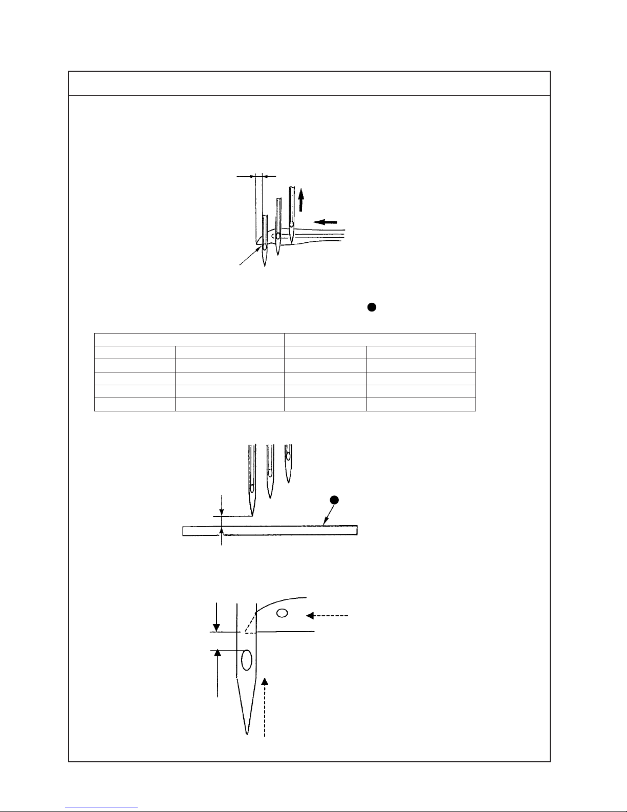
(9) Height of the needle
1. It is the standard that the top end of needle eyelet of left needle aligns with the bottom end of looper when
the top end of looper passes the rear of the needle from the extreme right position and protrudes from the
left end of left needle by approximately 1 mm (Calculated value : 1.1 mm), dimension B. (Dimension B :
standard needle size #10S)
A
C
Reference : Dimension C, height of left needle from top surface A of throat plate
1.2 to 1.4mm
Standard Adjustment
Reference : The scooping height of the looper, the dimension from the top end of the left needle eyelet to
the tip of the looper, is 1.2 to 1.4mm.
Unit : mm
B
To align
2-needle 3-needle
Needle gauge Height of left needle C Needle gauge Height of left needle C
4.0 8.8 – –
4.8 8.3 – –
––5.6 7.8
––6.4 7.5
– 25 –
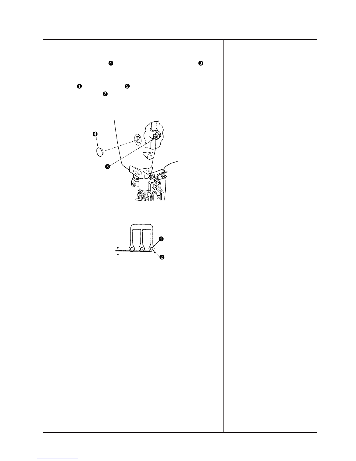
1. Remove rubber cap in the face plate, loosen setscrew in the
needle bar bracket and adjust the height of the needle bar.
2. After adjusting the height, equally adjust the clearance A between
needle and needle hole in the throat plate and fix the needle
bar with setscrew in the needle bar bracket.
o When the height of the needle
is excessively different, stitch
skipping, needle breakage,
thread breakage, etc. will be
caused.
A
Equal
Adjustment Procedure
Results of Improper Adjustment

– 26 –
(10)Locus and longitudinal motion of the looper
1. It is the standard that the top end of left needle touches
the position of 1/4 to 1/3 from the bottom face of the back
of the looper when the looper returns from the extreme
left position in the standard looper motion locus.
2. Longitudinal motion timing of the looper
(1) The standard position of the cam is the position where
the engraved marker line on looper longitudinal motion
eccentric cam is adjusted to the center of notches
on looper driving shaft.
(2) It is the standard motion locus of the looper that the top
end of looper lightly comes in contact with right needle
and middle needle, and passes left needle with a
clearance of 0.05 to 0.1 mm when the rear needle guard
does not work.
0.05 to 0.1mm
1/4/ to 1/3
A
B
C
D
Standard Adjustment
 Loading...