

Page 1
R
ENGINEER’S MANUAL
13371604
No.E361-01
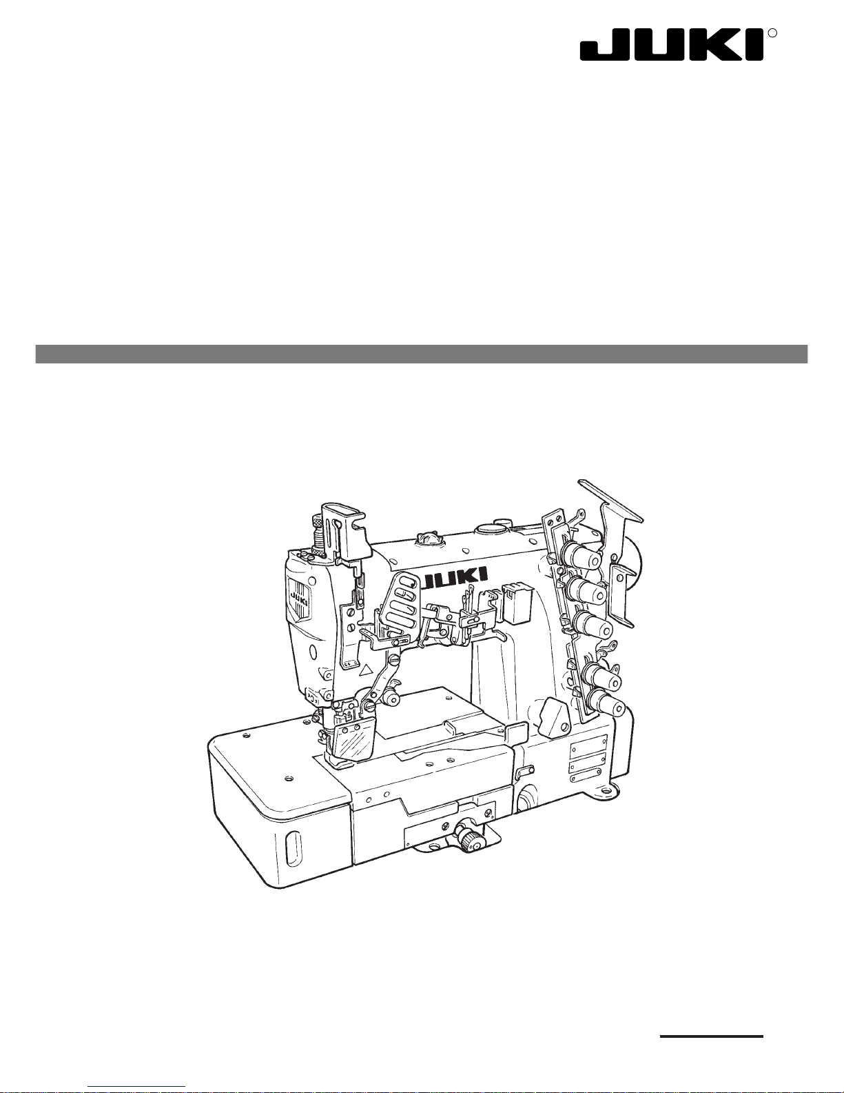
High-speed, Flat-bed Coverstitch Machine
MF-7700 Series
Page 2

PREFACE
This Engineer’s Manual is written for the technical personnel who are responsible for the service and maintenance of
the machine.
The Instruction Manual for these machines intended for the maintenance personnel and operators at an apparel
factory contains operating instructions in detail. And this manual describes “Standard Adjustment”, “Adjustment
Procedures”, “Results of Improper Adjustment”, and other important information which are not covered by the Instruction
Manual.
It is advisable to use the relevant Instruction Manual and Parts List together with this Engineer’s Manual when carrying
out the maintenance of these machines.
In addition, for the motor for the sewing machine with thread trimmer, refer to the separate Instruction Manual or
Engineer’s Manual for the motor. And for the control panel, refer to the Instruction Manual for the control panel.
This manual gives the “Standard Adjustment” on the former page under which the most basic adjustment value is
described, and on the latter page “Results of Improper Adjustment” under which stitching errors and troubles arising
from mechanical failures are described together with the “Adjustment Procedures”.
Page 3

CONTENTS
1. SPECIFICATIONS ............................................................................................. 1
2. CONFIGURATION OF THE MACHINE COMPONENTS .................................. 2
3. MODEL NUMBERING SYSTEM ....................................................................... 3
4. MOTOR PULLEY AND BELT MF-7700 Series ................................................ 4
5. STANDARD ADJUSTMENT ............................................................................. 5
(1) Threading the machine head ........................................................................................... 5
(2) Adjusting the rocking thread take-up............................................................................. 7
(3) Adjusting the position of the needle thread guide rod ................................................. 9
(4) Adjusting the position of the thread receiver .............................................................. 11
(5) Adjusting the position of the spreader thread guide and spreader thread take-up ...... 13
(6) Adjusting the spreader .................................................................................................. 15
(7) Adjusting the timing relation between the looper and needle bar............................. 19
(8) Retuming amount of the looper .................................................................................... 21
(9) Height of the needle ....................................................................................................... 23
(10) Locus and longitudinal motion of the looper ............................................................ 25
(11) Adjusting the needle guard ......................................................................................... 27
(12) Instlling cover of the looper and needle guard after adjusting................................ 31
(13) Adjusting the feed dog................................................................................................. 33
(14) Adjusting the feed relation .......................................................................................... 39
(15) Adjusting the presser foot........................................................................................... 41
(16) Adjusting the micro-lifter............................................................................................. 43
(17) Adjusting the looper thread cam ................................................................................ 45
(18) How to change needle bar stroke ............................................................................... 47
(19) How to change the spreader ....................................................................................... 51
(20) With reagard to lubrication .......................................................................................... 53
(21) Adjusting and setting SC-380...................................................................................... 55
6. TROUBLES AND CORRECTIVE MEASURES............................................... 57
7. DRAWING OF TABLE (SEMI-SUBMERGED TYPE) ..................................... 71
Page 4

–1 –
No. Item Specifications
1 Model name High-speed, flat-bed coverstitch machine
2 Model MF-7700 series
3 Stitch type ISO standard 406, 407, 602, and 605
4 Example of application Hemming and covering for knits and general knitted fabrics
5 Max. sewing speed Max. 6,500 rpm (at the time of intermittent operation)
6 Needle gauge 3-needle ... 4.8 mm, 5.6 mm, and 6.4 mm
2-needle ... 4.0 mm (3.2 mm can be accepted as special order)
7 Differential feed ratio 1 : 0.7 to 1 : 2 (stitch length : less than 2.5 mm)
Micro-differential feed adjustment mechanism is provided. (Micro-adjustment)
8 Stitch length 1.2 mm to 3.6 mm (can be adjusted up to 4.4 mm)
9 Needle UY128GAS ORGAN #9S to #14S (standard #10S)
(SCHMETZ Nm65 to Nm90, standard Nm70)
10 Needle bar stroke 31mm (standard), possible up to 33 mm by adjustment)
11 Dimensions (Height) 451 x (Width) 515 x (Length) 265
12 Weight 46kg
13 Lift of presser foot 8 mm (needle gauge : 5.6 mm without top covering), and 5 mm (with top covering)
Micro-lifter mechanism is provided.
14 Feed adjustment method Main feed ... dial type stitch pitch adjustment method
Differential feed ... lever adjustment method (micro-adjustment mechanism is provided.)
15 Looper mechanism Spherical rod drive method
16 Lubricating system Forced lubrication method by gear pump
17 Lubricating oil JUKI MACHINE OIL 18 (Equivalent to ISO VG18)
18 Oil reservoir capacity Oil gauge lower line : 600 cc to upper line : 900 cc
19 Installation Semi-submerged type
20 Needle tip, needle thread and Provided as standard
silicon oil lubricating unit
21 Noise Workplace-related noise at sewing speed
n= 5000 min-1 : LPA ≦78 dB (A)
Noise measurement according to DIN 45635-48-A-1.
1. SPECIFICATIONS
Page 5
–2 –
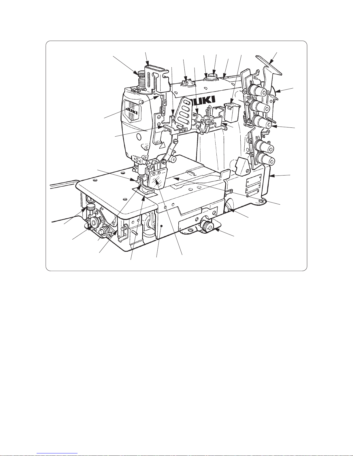
2.CONFIGURATION OF THE MACHINE COMPONENTS
1 Presser spring regulator !0 Thread tension nut !9 Thread trimming knife
2 Needle bar thread take-up cover !1 Oil gauge @0 Rocking thread take-up receiver
3 Oil circulation identification window !2 Feed regulating knob @1 Rocking thread take-up
4 Oil hole cap !3 Eye guard cover @2 Front cover
5 Micro-lifter !4 Throat plate @3 Slide cover
6 "Oil" indication !5 Needle tip silicon oil lubricating unit @4 Needle bar thread take-up thread
7 Needle thread silicon !6 Differential lock nut receiver
oil lubricating unit !7 Micro-adjustment knob @5
Rocking thread take-up thread guide
8 Thread guide No. 1 !8 Finger guard @6 Silicon container thread guide
9 Upper pulley @7 Belt cover
1
2
3
4
5
6
7
8
9
!0
!1
!2
!3
!4
!5
!6
!7
!8
!9
@0
@1
@7
@3
@2
@5
@4
@6
Page 6
–3 –
3.MODEL NUMBERING SYSTEM
High-Speed, Flat-bed Coverstitch Machine
Applicable model : MF-7700 Series
3~6 Model code
7722 2-needle top & bottom covering stitch
7723 3-needle top & bottom covering stitch
Application code
7~9 Application Description
U10 For universal Lapseam, Covering, Hemming
C10 For collarette Collarette
10 Tongue shape of throat plate
B B-type (Standard)
Availabilty
11~12 Needle gauge For 2-needle For 3-needle U10 C10
40 4.0mm Avail – – Avail
48 4.8mm Avail Avail Avail –
56 5.6mm Avail Avail Avail Avail
64 6.4mm Avail Avail Avail Avail
14~22 Device and attachment
(blank) Not provided
24 Destination
A Standard
25 Accessory
A Standard
* When device or attachment is one, delete slash (/) of 13th digit.
1 2 3 4 5 6 7 8 9 10111213141516171819202122232425
MF 7 7 B / / –
Page 7

–4 –
50Hz 60Hz
Pulley size (mm) Belt size (inch) Pulley size (mm) Belt size (inch)
4,500 ø 100 M-35 ø 85 M-35
4,800 ø 105 M-36 ø 90 M-35
5,000 ø 115 M-36 ø 95 M-35
5,500 ø 125 M-37 ø 105 M-36
5,800 ø 130 M-37 ø 110 M-36
6,000 ø 135 M-37 ø 115 M-37
6,200 ø 140 M-38 ø 120 M-38
6,500 ø 150 M-39 ø 125 M-38
4. MOTOR PULLEY AND BELT MF-7700 Series
1 . The table shows the numbers when a 3-phase 2-pole 400 W clutch motor (1 / 2 HP) is used.
2 . The commercially-available motor pulley near to the counted value is designated since the outside diameter of the
commercially-available motor pulley counts by 5 mm.
3 . When you use a new sewing machine, use the machine at a speed of 5,000 rpm or less for the first 200 hours
(approximately one month). A good result can be obtained in terms of the durability.
(Caution) 1. Use a motor pulley which is adaptable to this sewing machine.
2. The sewing speed exceeds the max. sewing speed of this sewing machine and machine trouble will be
caused unless a motor pulley which is adaptable to this sewing machine is used.
Sewing
speed(rpm)
Page 8
–5 –
5. STANDARD ADJUSTMENT
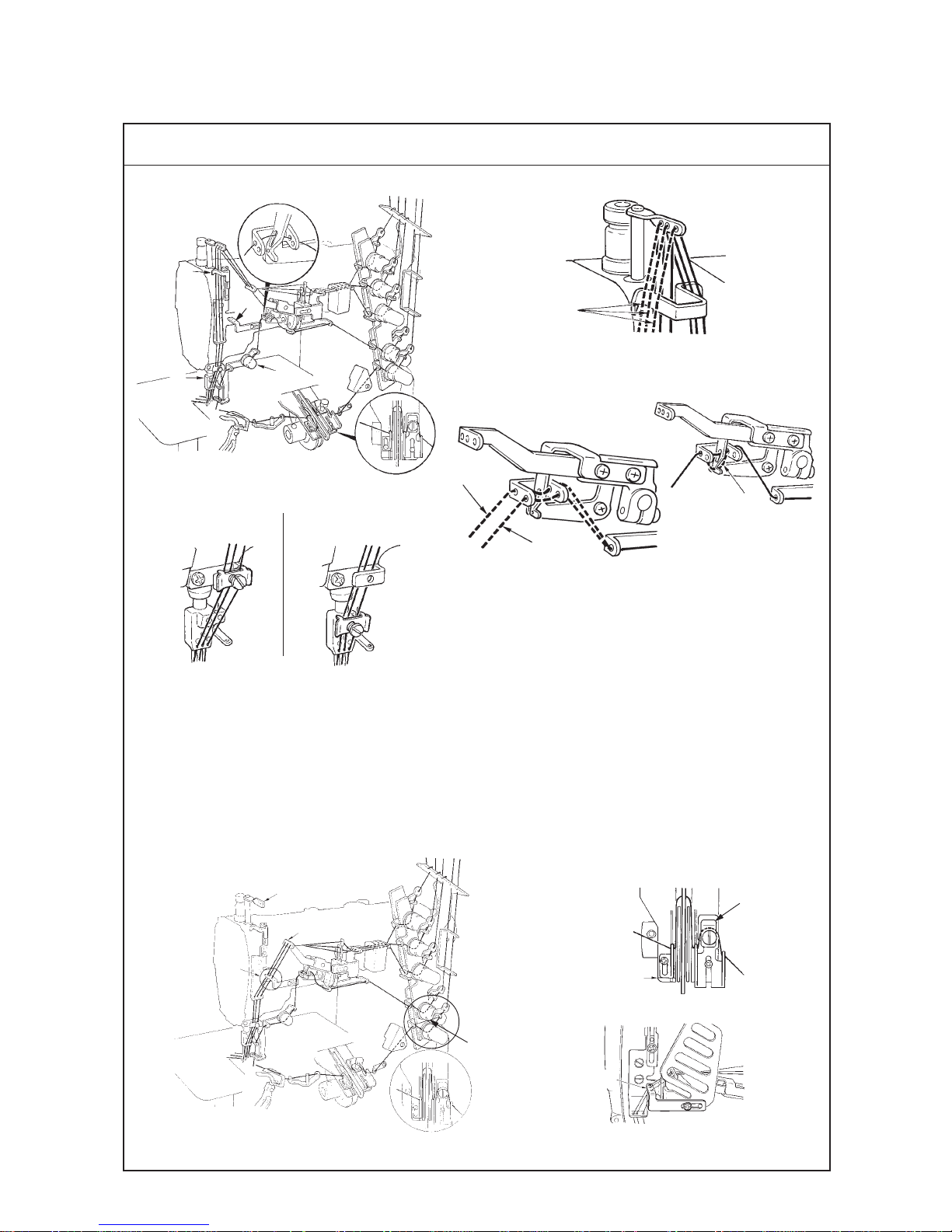
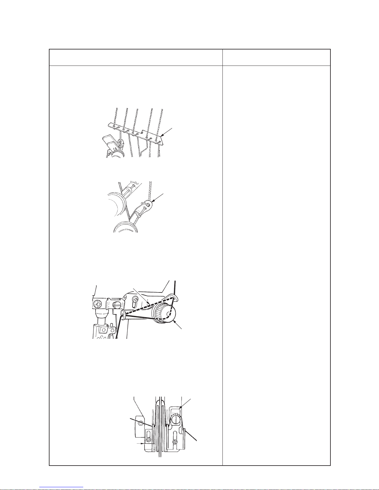
1. Threading for standard seame
(Caution) In case of threading for standard seams, rocking thread take-up thread guide 5 is not used.
(Caution) In case of the soft seams, rocking thread take-up thread guide 5 is used.
2
When covering thread is
excessively tense = D
When covering thread is
excessively loosened = B
When covering thread is
excessively loosened even
after passing B = C
B
C
D
1
Broken lines A when stretcher
thread is used
A
Standard Adjustment
(1) Threading the machine head
2. Threading for soft seams
(1) Do not pass needle thread through needle bar thread take-up 8.
(2) When soft seams are required, change the threading of needle thread and slide the position of looper thread cam
eyelet.
(3) Do not pass needle thread through needle bar thread take-up 8. Pass the thread from rocking thread take-up 9 to
rocking thread take-up thread guide
5.
(4) Other points are same as those of “1. Threading for standard seame”.
In case of soft seams
Engraved marker line
Left
Right
7
5
When using more
stretchable thread
When using less
stretchable thread
3
8
9
5
E
1
2
4
5
3
Page 9
–6 –
1. When motion of thread is very rough, and stable seams can not be
obtained, there are cases where the condition can be improved by
the following threading.
(1) Wind thread around 1st thread guide 6.
(2) Wind thread around the thread tension thread guide !0.
2. When using more stretchable thread (wooly thread or the like), the
threading as given below does not make thread stretch and neat
seams can be obtained.
(1) Do not pass thread through spreader auxiliary thread tension 4.
(2) Do not pass thread through the looper thread tension disk.
Refer to section E.
(Caution) Even when using wooly thread or the like, seams are more
stabilized by passing thread through looper thread
auxiliary thread tension 7.
™ When threading is not properly
performed, not only sewing trouble
occurs, but also needle breakage is
caused. So, be careful.
Engraved marker line
7
Do not pass thread.
4
Standard Adjustment Results of lmproper Adjustment
6
!0
Page 10
–7 –
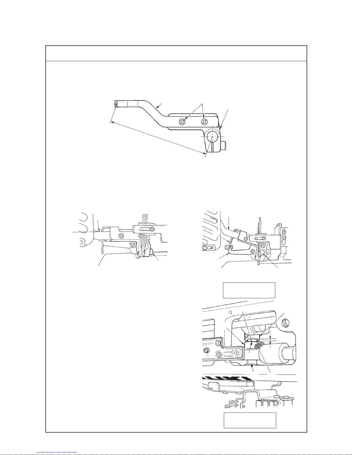
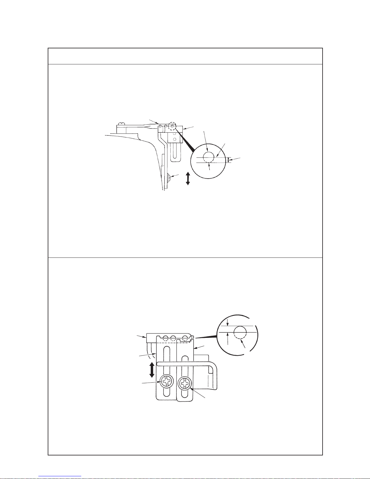
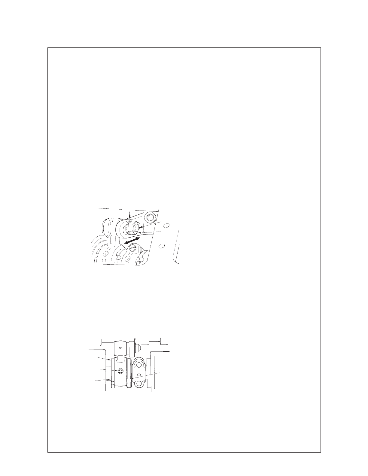
(2) Adjusting the rocking thread take-up
Standard Adjustment
1. Length of the rocking thread take-up
(1) It is the standard that the length of rocking thread take-up 2 from the center of the shaft of rocking thread take-up
support arm 4 to the thread hole face of rocking thread take-up 2 is 95 mm.
2. Position of the rocking thread take-up
(1) Install so that rocking thread take-up 2 is flush with rocking thread take-up 2 when the needle bar is in its lowest
position.
3. Timing of the rocking thread take-up
(1) It is the standard timing that rocking thread take-up 2 is in
its lowest position as well when the needle bar is in its lowest
position.
Timing of rocking thread take-up 2 is performed by adjusting
the position of rocking thread take-up ball arm 8.
4. Relation between the timing of rocking thread take-up and
the needle thread loop
(1) When using the excessively stretchable thread or the hard-
to-stretch thread, the size of needle thread loop can be
changed by by changing the timing of rocking thread takeup 2.
(2) Relation between the timing of the rocking thread take-up
and the size of needle thread loop is as shown in the table
on the next page.
(The relation becomes reverse when using the needle bar
thread take-up = standard seams and when it is not used =
soft seams. So, be careful.)
1
2
4
95 mm
2
7
3
6
2
5
Flush
!1
3
8
4mm
Anti-operator’s side
Operator’s side
9
!2
/
/
!0
Page 11
–8 –
Standard Adjustment Results of lmproper Adjustment
™ When length of rocking thread take-
up 2 is lengthened, needle thread is
tightened.
(Caution) When lengthening rocking
thread take-up 2, check
whether it comes in contact
with the thread take-up cover.
™ When length of rocking thread take-
up 2 is shortened, needle thread is
loosened.
™ When installing position of rocking
thread take-up 2 is raised, needle
thread is loosened when the needle
bar thread take-up is used, and needle
thread is tightened when the needle
bar thread take-up is not used.
1. Length of the rocking thread take-up
(1) Loosen screws 1 and move rocking thread take-up 2 to the right
or left to adjust the length.
2. Position of the rocking thread take-up
(1) Loosen screw 5 and move rocking thread take-up 2 up or down
to adjust the position.
(Caution) When adjusting the position of rocking thread take-up 2,
adjust the rocking thread take-up to the same plane of the
edge of rocking thread take-up shaft 3 and fix it so that
spreader thread take-up 6 and spreader thread guide 7
do not come in contact with each other.
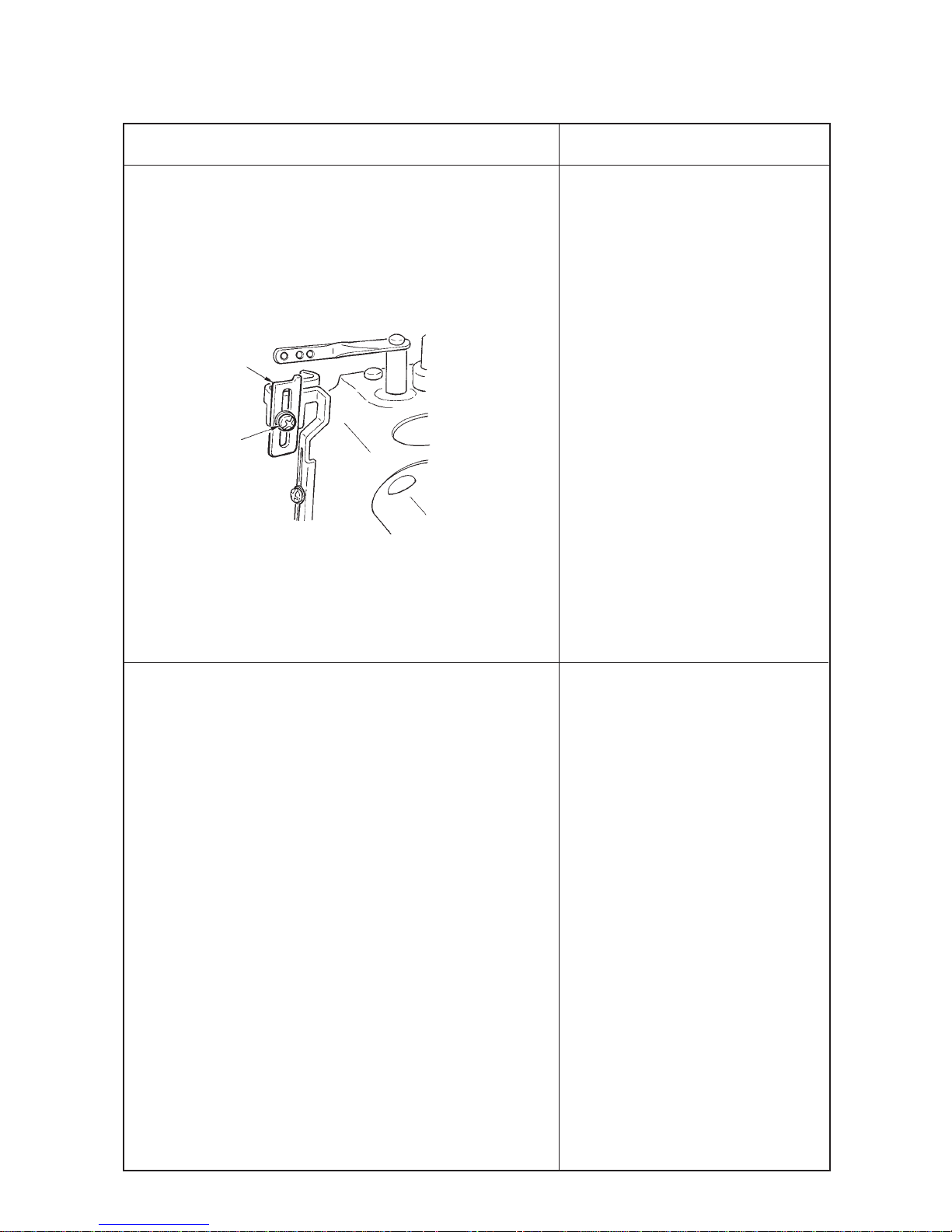
3. To adjust the timing of the rocking thread take-up 2 , remove the top
cover, loosen setscrew 9 in the rocking thread take-up ball arm and
move the position of rocking thread take-up ball arm 8 to and fro.
(1) Standard adjustment figure is the position where the rear end (anti-
operator’s side) of rocking thread take-up ball arm 8 aligns with engraved
marker line !0 on rocking thread take-up shaft 3. (As the standard at this
time, note that the clearance provided between the rear end of rocking
thread take-up ball arm 8 and thrust collar !1 is 4 mm.)
(Caution) 1. When loosening screw 9 in rocking thread take-up
ball arm 8, there is a case where rocking thread take-up
2 rotates by its weight. After the adjustment, be sure to
check the rocking position (flush at the lowest position)
of rocking thread take-up 2.
2. When moving rocking thread take-up ball arm 8 to the
operator’s side, adjust rocking thread take-up ball arm
8 within the range where it does not come in contact
with rocking thread take-up bushing !2 (operator’s side).
4. Relation between timing of rocking thread take-up and needle
thread loop
When needle bar thread take-up is used Loop becomes small. Loop becomes large.
When needle bar thread take-up is not used Loop becomes large. Loop becomes small.
Advance timing
(Move to anti-operator’s side.)
Delay timing
(Move to operator’s side.)
Adjusting procedure is the same as step 3. Loosen setscrew 9 in rocking thread take-up ball arm 8 and adjust
the position of rocking thread take-up ball arm 8.
(Caution) Adjust the timing of rocking thread take-up 2 each time in accordance with thread used or conditions.
Page 12
–9 –
Standard Adjustment
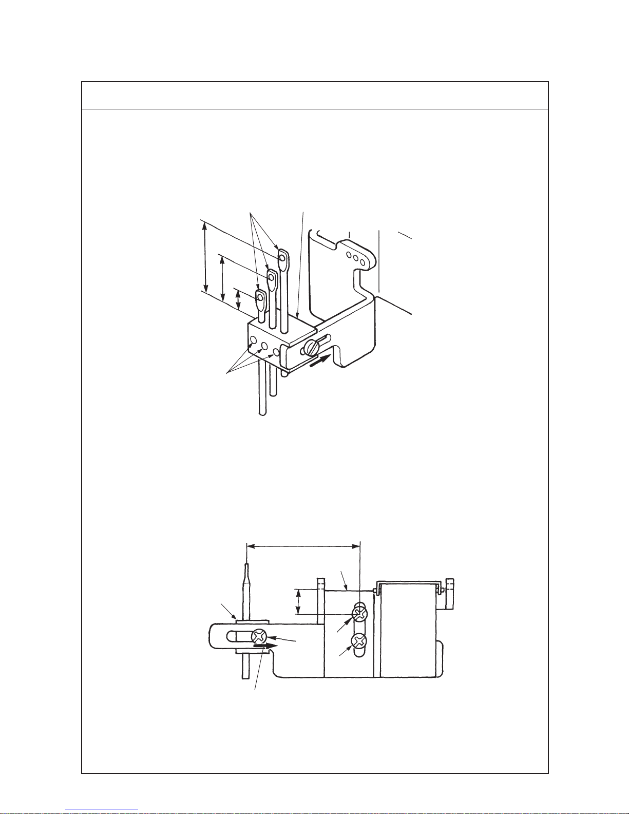
1. Position of the needle thread guide rod
(1) It is the standard that the height of needle thread guide rods 1 is the position where the dimensions from the top
surface of needle thread guide base 2 to the bottom end of the hole are as follows.
Left needle A : 7 mm
Middle needle B : 15 mm
Right needle C : 23 mm
2. Adjusting the position of needle thread guide base and silicon container thread guide
(1) It is the standard that the height of silicon containder thread guide 4 (refer to 2. CONFIGURATION OF THE
MACHINE COMPONENTS) is the position where the height from the center of setscrew 5 to the bottom end of
thread hole is 9 mm.
(2) Move the lateral position of needle thread guide base 2 fully to the right of slot (43 mm).
Extreme right position
C
B
A
A : 7mm B : 15mm C : 23mm
1
2
3
Extreme right position
7
43mm
9mm
5
4
6
2
(3) Adjusting the position of the needle thread guide rod
Page 13

–10 –
Standard Adjustment Results of lmproper Adjustment
1. Loosen setscrews 3, adjust the height of respective needle thread
guide rods 1, and fix the rods with setscrews 3.
(Caution) 1. Move the lateral position of needle thread guide base 2
fully to the right of slot.
2. When adjusting the height of needle thread guide rods
1, install the rods so that the thread holes are parallel to
the thread holes of silicon container thread guide 4 so
that excessive resistance is not applied to threads.
2. Adjusting the position of needle thread guide base and silicon
container thread guide
(1) Loosen setscrews 5 and 6 and move silicon container thread
guide 4 up or down to adjust the height.
(2) Loosen setscrew 7 and adjust the lateral position of needle thread
guide base 2.
™ When needle thread guide rod 1 is
raised, needle thread is loosened.
™ When needle thread guide rod 1 is
lowered, needle thread is tightened.
™ When silicon container thread guide
4 is raised, needle thread is loosened.
™ When silicon container thread guide
4 is lowered, needle thread is
tightened.
™ When needle thread guide base 2 is
moved to the left, needle thread is
loosened.
Page 14
–11 –
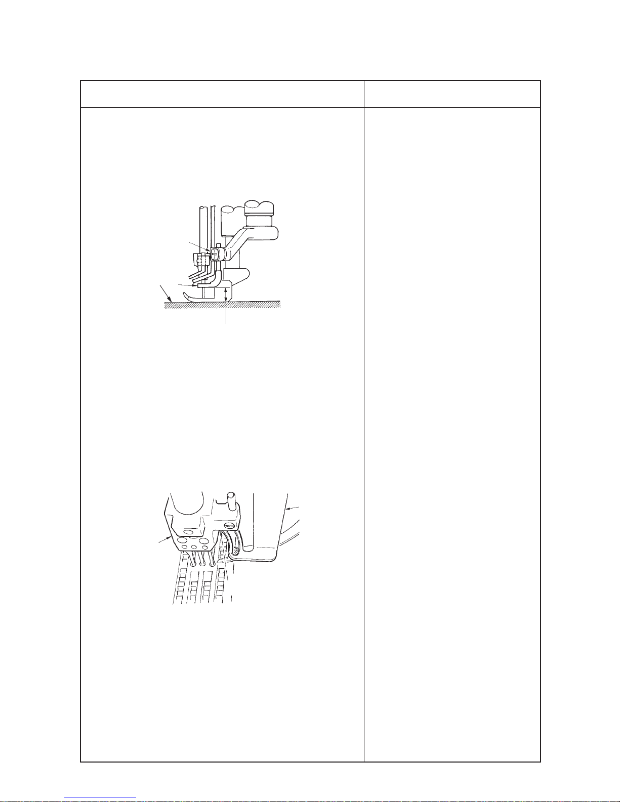
(4) Adjusting the position of the thread receiver
Standard Adjustment
1. Position of the needle bar thread take-up thread receiver (in case of standard seams)
(1) It is the standard that the height of needle bar thread take-up thread receiver 1 is in the position where the bottom
end of thread hole to the center of needle bar thread take-up 2 aligns with the top surface of needle bar thread
take-up thread receiver 1 when the needle bar is in its lowest position.
1. Position of the rocking thread take-up thread receiver (in case of soft seams)
(In case thread is not passed through needle bar thread take-up 2)
(1) It is the standard that the height of rocking thread take-up receiver 7 is in the position where the top surface of
rocking thread take-up receiver 7 is in the range of the center to the top end of thread hole 9 of rocking thread
take-up 8 when rocking thread take-up 8 is in its lowest position.
This range
6
!0
!1
7
8
9
This range
1
2
3
Thread hole
Center of hole
To align
Page 15
–12 –
Standard Adjustment Results of lmproper Adjustment
1. Loosen setscrew 3 and move needle bar thread take-up thread
receiver 1 up or down to adjust the height.
2. When desired to make needle bar thread take-up thread receiver
1 work especially on the right needle where loop is hard to be
made, adjust the height of right needle thread receiver 4 with
setscrew 5.
1. Loosen setscrew !0 and move rocking thread take-up receiver 7 up
or down to adjust the height.
2. When desired to make rocking thread take-up receiver 7 work
especially on the right needle where loop is hard to be made, adjust
the height of the right needle thread receiver 6 with screw !1.
™ When the needle bar thread take-up
thread receiver 1 is raised, loop
becomes large.
™ When the needle bar thread take-up
thread receiver 1 is excessively
raised,
4
5
Page 16
–13 –
Standard Adjustment
(5) Adjusting the position of the spreader thread guide and spreader thread take-up
1. Relation of the position between spreader thread take-up 1 and spreader thread guide 2 is the standard when
the top end of thread hole 3 of spreader thread guide 2 aligns with the bottom end of slot 5 of spreader thread
take-up 1 when spreader thread take-up 1 is in its highest position.
Adjust the relation of the position so that thread is moderately stretched when spreader thread take-up 1 is in its
highest position in accordance with thread used or conditions.
2. Standard position of the spreader auxiliary thread tension
Standard adjustment figure of the spreader auxiliary thread tension is the standard when the top end of thread
tension rod 6 is flush with knob 7.
To align
Highest position
1
5
2
3
4
1
8
A
2
2
4
9
3
5
1
8
7
6
Page 17

–14 –
1. Loosen setscrews 4 in spreader thread guide 2 and adjust the
position of spreader thread guide 2. (Spreader thread take-up 1
is fixed to rocking thread take-up 9 and can not be adjusted in the
height direction.)
2. After the adjustment, turn the sewing machine by hand and check
whether spreader thread take-up 1 comes in contact with spreader
thread guide 2, or section A of clearance is too small.
3. Adjusting procedure of the clearance
(1) Loosen setscrews 4 in spreader thread guide 2 and adjust in the
lateral direction, or loosen setscrews 8 in the rocking thread takeup and move spreader thread take-up 1 to the right or left to adjust
the clearance.
(Caution) When loosening setscrews 8 in the rocking thread take-
up and adjusting the position of spreader thread take-up
1, adjust so that 95, length of rocking thread take-up 9
(95mm) does not change.
Standard Adjustment Results of lmproper Adjustment
™ When the relation of position between
spreader thread take-up 1 and the
spreader thread guide is not proper,
sewing troubles such as stitch skipping
and the like will be caused.
™ If thread is less stretched and
slackness of thread occurs at the
thread take-up section when spreader
thread take-up 1 is in its highest
position, the spreader fails to pick up
thread and stitch skipping occurs.
™ If stretch or feeding of thread is
excessive when spreader thread takeup 1 is in its highest position, not only
thread on the seam side is drawn and
needle thread can not be tightened, but
also needle bend or needle breakage
will be caused.
™ If stretch or feeding of thread is
excessive when spreader thread takeup 1 is in its lowest position, thread
slacks when the spreader moves from
left to right and stitch skipping occurs.
Page 18
–15 –
Standard Adjustment
1. Height of the spreader
It is the standard that the height from the top surface of throat plate 2 to the bottom surface of spreader 1 is 8.3
to 8.7 mm.
2. Longitudinal position of the spreader
It is the standard that when spreader 1 returns from the extreme left position to the right and top end A of thread
hooking section reaches to the front of left needle, the clearance between the spreader and the left needle is 0.1
to 0.3 mm.
3. Protruding amount
It is the standard that the dimension from the center of left needle to top end A of thread hooking section, when
spreader 1 is in the extreme left position, is 4.5 to 5.5 mm.
4. Spreader stroke
It is the standard that the spreader stroke is 16 to 18 mm at the stroke of thread hooking section.
5. Timing of the spreader
Standard position is the position where the spreader 1 is in the extreme left position when the needle bar comes
down from the upper dead point by 1.1±0.1 mm.
(6) Adjusting the spreader
8.3 to 8.7 mm
4
1
2
3
0.1 to 0.3 mm
4.5 to 5.5 mm
16.0 to 18.0 mm
Extreme left position
1
A
A
1
3
Page 19
–16 –
Standard Adjustment Results of lmproper Adjustment
1. Adjusting the height of the spreader
2. Adjusting the longitudinal position of the spreader
Loosen setscrew 3 and adjust the height and longitudinal position
of the spreader 1.
3. Protruding amount of the spreader
Loosen setscrew 4 in the spreader folder and adjust the protruding
amount. Adjust aiming the adjustment figure of 5 mm.
4. Adjusting the spreader stroke
Standard position is the position where the engraved marker line of
spreader drive lever 5 aligns with the center of the shaft of
connecting pin 6. When desired to increase the stroke, loosen
lock nut 7 and move in the right direction. When desired to decrease
the stroke, loosen lock nut 7 and move in the left direction. Adjust
aiming the adjustment figure of 17 mm.
5. Adjusting the timing between the needle bar and the spreader
When changing the timing, loosen two setscrews 9 in spreader
eccentric cam 8 to adjust. Standard position is the position where
notch !0 in the main shaft aligns with notch !1 in spreader eccentric
cam. When changing, turn the upper pulley and change with
spreader eccentric cam 8 fixed.
™ Height of the spreader is improper,
stitch skipping of spreader occurs.
™ Adjust the height in accordance with
the needle gauge.
™ Even when the protruding amount is
excessive or insufficient, stitch
skipping of spreader will be caused.
™ When the protruding amount is
insufficient, it will be the cause for left
needle not to scoop covering thread
at overlapped section.
™ When the stroke is increased, disorder
of covering thread stitching will be
caused.
™ When the stroke is decreased, stitch
skipping of spreader will be caused.
™ When the timing is excessively
advanced, needle does not take
covering thread when it comes down
and stitch skipping will be caused.
™ When the timing is excessively
retarded, resistance increases when
covering thread slips out from the
spreader and a load is applied to the
right needle. As a result, needle
breakage or stitch skipping will be
caused.
(Caution) When changing, temporarily
tighten No. 2 screw in the
rotation direction of setscrews
9 and turn the upper pulley
to change.
8
9
!0
!1
7
6
5
Page 20

–17 –
Standard Adjustment
6. Adjustment figures of the spreader thread guide
(1) It is the standard that the clearance provided between spreader 1 and spreader thread guide !2 is 0.4 to 1.0 mm.
(2) It is the standard that the clearance provided between spreader thread guide !2 and needle clamp thread guide !3
is 0.8 to 1.2 mm.
(3) Lateral position of the spreader thread guide
Top end of thread hooking section D of the spreader aligns with center E of slot C in spreader thread guide !2
when spreader 1 is in the extreme right position.
(6) Adjusting the spreader
0.8 to 1.2 mm
0.4 to 1.0 mm
1
!4
!3
!2
1
C
E
D
!3
!4
!5
!2
!2
Page 21
–18 –
Standard Adjustment Results of lmproper Adjustment
6. Spreader thread guide
(1) Adjust the height of spreader 1 to 8.3 to 8.7 mm. Loosen setscrews
!5 in the spreader thread guide and adjust the clearance provided
between the top surface of spreader 1 and spreader thread guide
!2 to 0.4 to 1.0 mm.
(2) Needle clamp thread guide
Loosen setscrew !4 in the needle clamp thread guide and adjust
the clearance provided between the needle clamp thread guide
and spreader thread guide !2 to 0.8 to 1.2 mm.
(3) For the lateral direction, align the hole of needle clamp thread guide
!3 to the prolonged line of the slot of spreader thread guide.
(Caution) When adjusting spreader thread guide !2 in the lateral
direction, check whether there is any contact at section B
(left side of spreader thread guide !2 and needle clamp !6)
™ When height or position of the
spreader thread guide is improper,
stitch skipping of spreader thread will
be caused.
™ When height or position of the needle
clamp thread guide is improper, stitch
skipping of spreader thread will be
caused.
!2
B
!6
8.3 to 8.7 mm
2
1
3
Page 22
–19 –
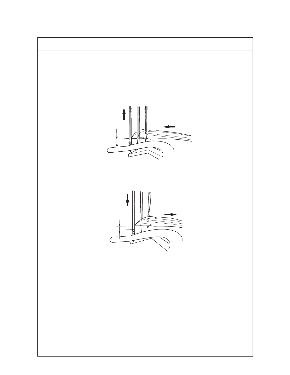
Standard Adjustment
(7) Adjusting the timing relation between the looper and needle bar
1. Timing relation between the looper and the needle bar (synchronization)
It is the standard that dimension A from the top end of needle eyelet to the blade point of looper passes the rear
of the needle and comes to the position of the right end of left needle is the same as dimension B from the top end
of needle eyelet to the blade point of looper when needle bar comes down from the upper dead point, the blade
point of looper passes the front of needle bar and comes to the position of the right end of left needle. (A=B)
Going of looper
A
Returning of looper
B
Page 23
–20 –
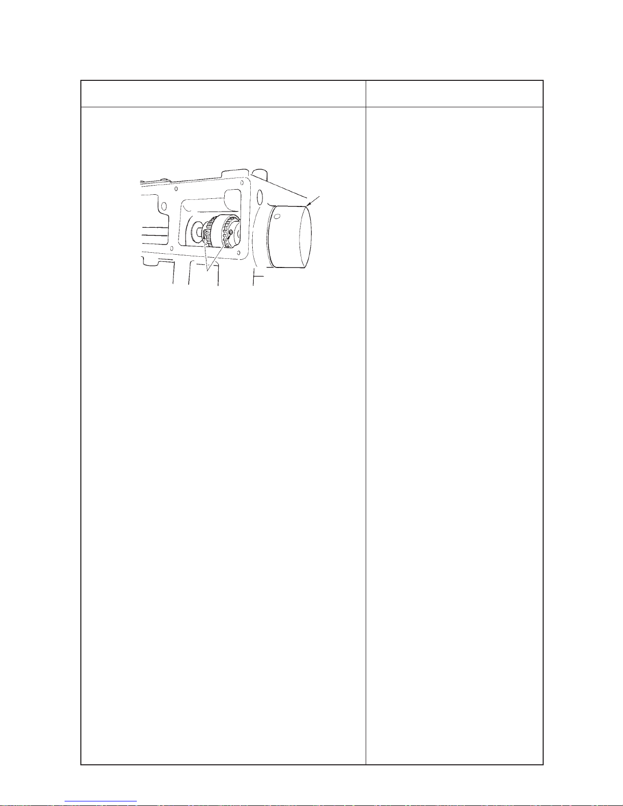
Standard Adjustment
Results of lmproper Adjustment
1. To adjust the timing relation between the needle and the looper,
remove the top cover, loosen four setscrews 1 in the sprocket and
turn upper pulley 2 in the state that the sprocket is held.
2. Adjusting procedure
(1) When adjusting the timing to "0" (zero)
1) In case dimension A when the looper advances is smaller than
dimension B when the looper retreats, the looper timing is retarded
(needle timing is advanced). In this case, loosen setscrews 1 in
the sprocket and finely turn upper pulley 2 in the reverse direction.
2) In case dimension A when the looper advances is larger than
dimension B when the looper retreats, the looper timing is advanced
(needle timing is retarded). In this case, loosen setscrews 1 in the
sprocket and finely turn upper pulley 2 in the normal direction.
(Caution) Be careful not to excessively turn upper pulley 2.
3. After the adjustment, fix four setscrews 1 in the sprocket.
™ When the difference in timing (going
and returning) of looper is excessively
large, stitch skipping or entangling of
needle thread will be caused.
2
1
Page 24

–21 –
Standard Adjustment
(8) Retuming amount of the looper
1. It is the standard that returning amount of looper 1 from top end of looper 1 to the center of needle bar is 6.5 mm
regardless of the needle gauge when looper 1 is in the extreme right position.
2. Returning amount of looper for each gauge (dimension A)
2-needle 3-needle
Needle gauge Returning amount A Needle gauge Returning amount A
3.2 4.9 – –
4 4.5 – –
4.8 4.1 4.8 4.1
5.6 3.7 5.6 3.7
6.4 3.3 6.4 3.3
(Dimension A is the dimension fromthe center of right needle to the top end of looper 1.)
Unit : mm
A
1
5
4
0 to 0.05 mm
1
6.5mm
Page 25

–22 –
Standard Adjustment Results of lmproper Adjustment
1. Loosen setscrew 2 in the looper holder and move looper holder 3
to the right and left to adjust.
2. After the adjustment, tighten setscrew 2 in the looper holder.
(Caution) When adjusting looper holder 3, adjust the lateral
position while being careful that the holder does not move
to and fro.
3. Longitudinal position
Adjust so that the clearance provided between blade point 5 of
looper and middle needle 4 is 0 to 0.05 mm when the top end of
looper comes to the center of middle needle from the extreme right
position.
After the adjustment, fix the looper holder with setscrew 2 in the
looper holder.
* Blade point 5 of the looper comes in contact with the right needle
when rear needle guard 6 fails to work. So, be careful.
™ When the returning amount is large,
loop of needle thread becomes large
and it is apt to fall. As a result, stitch
skipping or thread breakage will be
caused, and stitch skipping on the
back is apt to occur.
In addition, thread tangling will be
caused.
™ When the returning amount is small,
loop of needle thread is small and
stitch skipping or thread breakage will
be caused.
In addition, thread tangling will be
caused.
2
1
3
6
Page 26

–23 –
Standard Adjustment
(9) Height of the needle
1. It is the standard that the top end of needle eyelet of left needle aligns with the bottom end of looper when the top
end of looper passes the rear of the needle from the extreme right position and protrudes from the left end of left
needle by approximately 1 mm (1.1 mm), dimension B.
To align
B
Reference : Dimension C, height of left needle from top surface A of throat plate
Unit : mm
2-needle 3-needle
Needle gauge Height of left needle C Needle gauge Height of left needle C
3.2 9.7 – –
4.0 9.3 – –
4.8 8.8 4.8 8.8
5.6 8.5 5.6 8.5
6.4 8.0 6.4 8.0
A
C
1.2 to 1.4 mm
2. Scooping height of looper, dimension from the top end of needle eyelet to the top end of looper is 1.2 to 1.4 mm.
Page 27

–24 –
Standard Adjustment Results of lmproper Adjustment
1. Remove rubber cap 4 in the face plate, loosen setscrew 3 in the
needle bar bracket and adjust the height of the needle bar.
2. After adjusting the height, equally adjust the clearance A between
needle 1 and needle hole 2 in the throat plate and fix the needle
bar with setscrew 3 in the needle bar bracket.
™ When the height of the needle is
excessively different, stitch skipping,
needle breakage, thread breakage,
etc. will be caused.
Equal
1
2
A
4
3
Page 28

–25 –
Standard Adjustment
(10) Locus and longitudinal motion of the looper
1. Standard longitudinal motion of the looper
(1) It is the standard that the top end of left needle touches the position of 1/4 to 1/3 from the bottom face of the back
of the looper when the looper returns from the extreme left position.
(2) The position where the engraved marker line on looper drive arm 2 aligns with the center of the shaft of pin is the
standard.
2. Locus of the looper
It is the standard locus of the looper that the
clearance between the top end of looper and
middle needle is within 0.05mm (when the rear
needle guard fails to work) and the looper
passes the left needle with a clearance of 0.1
to 0.2 mm.
The standard position of the cam is the position
where the notch of looper longitudinal motion
eccentric cam 4 aligns with notches 5 of
looper driving shaft.
0.1 to 0.2 mm
2.5 to 2.7mm
Lower pulley side
4
5
6
2
3
+
–
1
1/4 to 1/3
Page 29

–26 –
Standard Adjustment Results of lmproper Adjustment
1. Changing the longitudinal motion of the looper
(1) Remove 11 setscrews in bed top cover 1 and remove the cover.
(2) When increasing the longitudinal motion of the looper, loosen nut
3 and lower the arm downward (+). from the engraved marker
line.
(3) When decreasing the longitudinal motion of the looper, loosen nut
3 raise the arm upward (-) from the engraved marker line.
Perform the adjustment in accordance with the needle used.
(Caution) After adjusting the longitudinal motion of the looper, move
the looper holder and re-adjust the longitudinal position
of the needle and the looper. (Refer to "(8) Returning
amount of the looper.)
2. Changing the locus of the looper
(1) Loosen two setscrews 6 in the cam and change the locus of the
looper by turning the upper pulley with the cam fixed.
When it is turned in the direction of rotation, the timing is retarded,
and when turning in the reverse direction of rotation, the timing is
advanced.
(Caution) 1. It i s possible to change the locus of the looper.
However, do not excessively change it from the standard
position.
2. When changing the locus of the looper, be sure to check
whether the top end of left needle touches the position
of 1/4 to 1/3 from the bottom face of the back of the looper.
™ When the longitudinal motion of the
looper is small, the rate that needle
touches the back of the looper is
increased and blunt needle tip will be
caused.
™ When the longitudinal motion of the
looper is large, the clearance provided
between the needle and the back of
the looper is increased and stitch
skipping at the time of returning of the
looper will be caused.
™When the timing is retarded, stitch
skipping is apt to occur at the time of
going of the looper, and especially the
clearance provided between the
looper and the left needle is widened.
Needle strongly touches the back of
the looper and blunt needle tip will be
caused.
™When the timing is advanced, stitch
skipping is apt to occur at the time of
returning of the looper.
Chain-off thread does not come out
smoothly.
™ When removing the top cover for
adjustment or the like, sealant is
peeled off. As a reult, oil leakage will
be caused.
Page 30

–27 –
Standard Adjustment
(11) Adjusting the needle guard
1. Standard position of the rear needle guard
(1) Lateral position of rear needle guard 1
It is the standard that the lateral position of rear needle guard 1 is the position where the rear needle guard
receives the needle in the range of B.
(2) Position of the height of the rear needle guard
It is the standard that ridge line A of rear needle guard 1 enters in the needle eyelet of right needle when the
needle bar is in its lower dead position.
(3) Pressing amount of the rear needle guard
When the top end of looper 3 comes from the extreme right position to the center of right needle, the clearance
provided between the needle and the top end of looper 3 becomes 0 to 0.05 mm. Make rear needle guard 1
lightly touch the right needle and the pressing amount of the top end of needle becomes 0.1 to 0.2 mm.
It is the standard for the middle needle that when the top end of looper 3 comes to the center of middle needle, the
clearance provided between the middle needle and the top end of looper becomes 0 to 0.05 mm and the pressing
amount of the top end of the needle is such an amount that rear needle guard 1 lightly touches the middle needle.
3
1
1
0 to 0.05 mm
0 to
0.05 mm
0.1 to 0.2 mm
1
2
A
B
Details of section A
Ridge line
Needle eyelet
Page 31

–28 –
Standard Adjustment Results of lmproper Adjustment
1. Loosen setscrew 4 in the rear needle guard holder and perform
the adjustment in the lateral direction.
2. Loosen setscrew 2 in the rear needle guard and perform adjustment
in the height direction and the direction of rotation.
3. After the adjustment, tighten setscrews 2 and 4.
(Caution) After the adjustment, check by manual turning whether
the top end of looper 3 does not come in contact with
the needle.
™ When the pressing amount of rear
needle guard 1 is small, needle
deflection increases and stitch
skipping, thread breakage, needle
breakage and worn-out of the top end
of looper 3 will be caused.
4
2
Page 32

–29 –
Standard Adjustment
(4) Timing of the rear needle guard
The standard position of rear needle guard cam 5 is the position where timing mark 7 in rear needle guard cam
5 aligns with the center of the notch of looper longitudinal cam 6.
2. Front needle guard
(1) It is the standard that the clearance provided between front needle guard 9 and the needle is 0.1 to 0.3 mm.
5
7
6
To align
(11) Adjusting the needle guard
0.1 to 0.3 mm
3
9
!0
Page 33

–30 –
Standard Adjustment Results of lmproper Adjustment
4. Remove the bed top cover.
Loosen two setscrews 8 in rear needle guard cam 5 and adjust
the timing.
When moving the cam in + direction, timing is advanced, and when
moving in – direction, it is retarded.
2. Loosen setscrew !0 in the front needle guard and adjust the
clearance.
Adjust so that the clearance provided between the needle and front
needle guard 9 is 0.1 to 0.3 mm when looper 3 moves from the
extreme right position to the left and passes the rear side of the
respective needles and fix the front needle guard with setscrew !0.
* Place front needle guard 9 as near as the needle to such an extent
that needle thread passes smoothly in accordance with kind and
thickness of thread.
Pulley side
™ The cam is excessively changed from
the standard position, needle
breakage or stitch skipping will be
caused.
™ When the front needle guard and the
needle come excessively near, stitch
skipping or needle breakage will be
caused.
8
(Caution) Check by manual turning whether the needle is pinched
with front needle guard 9 and the rear needle guard.
–
+
3
9
!0
Page 34

–31 –
Standard Adjustment
(12) Instlling cover of the looper and needle guard after adjusting
1. Installing bed top cover 1
1
A
Page 35

–32 –
Standard Adjustment Results of lmproper Adjustment
1. When the adjustment of (10) Locus and longitudinal motion of the
looper or (11) Adjusting the needle guard has been performed, apply
sealant to section A and install bed top cover 1
™ When removing bed top cover 1 for
adjustment or the like, sealant is
peeled off and oil leakage will be
caused.
Page 36

–33 –
Standard Adjustment
(13) Adjusting the feed dog
1. Height of the feed dog
It is the standard that the height of feed dogs (main feed dog 2 and differential feed dog 4) is 1 mm from the top
surface of the throat plate 1 when feed dogs 2 and 4 are in the highest position.
2. Tilt of the feed dog
It is the standard that the tilt of feed dogs 2 and 4 is flush with throat plate 1 when feed dogs 2 and 4 are in the
highest position.
7
3
8
9
Flush
1mm
2
56
1
4
Page 37

–34 –
Standard Adjustment Results of lmproper Adjustment
1. Loosen setscrew 7 in the differential feed dog and setscrew 3 in
the main feed dog, and adjust the height.
(1) Adjust the top surface of throat plate 1 and the height of the rear
end of main feed dog 2 to 1 mm when feed dogs 2 and 4 come
to the highest position, and fix the main feed dog with setscrew 3
in the main feed dog.
(2) Fot the height of differential feed dog 4, adjust the height of front
end 5 of main feed dog 2 and rear end 6 of differential feed dog
4, and fix the differential feed dog with setscrew 7 in the differential
feed dog.
2. Adjusting the tilt of the feed dog
(1) Remove rubber plug 8 in the cover located in the rear of the bed
and loosen the setscrew in the feed tilt adjustment shaft located in
the rear with a hexagonal wrench key of 2.5 mm.
(2) When turning feed dog tilt adjustment shaft 9 to the right or left,
the top ends of feed dogs 2 and 4 move up or down and the tilt of
feed dogs 2 and 4 can be adjusted.
(Caution) After the adjustment check the height of feed dogs 2
and 4.
™ When the position of the feed dog is
high, stitch skipping, defective chainoff, return of feed, etc. will be caused.
Throat plate comes in contact with
feed dod and damage of components
or abnormal noise will be caused.
™ When the position of the feed dog is
low, the stitch length becomes short
when the sewing is finished and
performance of getting over the
overlapped section is deteriorated.
™ When the position of the feed dog is
excessively low, looper and feed dog
may come in contact with each other.
™ When the tilt of the feed dog is raised
toward you, performance of catching
material is improved.
™ When the tilt of the feed dog is lowered
toward you, it is effective in irregular
stitches and puckering.
Page 38

–35 –
Standard Adjustment
(13) Adjusting the feed dog
3. Lateral position of the feed dog
It is the standard of the lateral position of the feed dog that the left and right clearances A of the feed dog in terms
of the slots of the throat plate are parallel and equal.
!1
!0
A
A
@1
@0@2@3
!7
!4
!6 !3
!2
!8
!5
!9
@4
@5
@6
Page 39

–36 –
Standard Adjustment Results of lmproper Adjustment
3. Adjusting the lateral position of the feed dog
(1) Remove the bed top cover and remove setscrews !1 in rocking bar
guide 2 !0.
(Caution) When setting the feed motion amount to 3.6 mm (max.)
and the differential feed ratio to 1 : 1 before the
adjustment, the adjustment at the time of assembling can
be performed with ease.
(2) Loosen setscrew !2 in the feed tilt adjustment shaft and setscrew
!3 in the feed tilt eccentric shaft !4. Move feed tilt eccentric shaft by
approximatelt 2mm in the left direction shaft, move feed tilt
adjustment shaft !5 by approximately 2mm in the right direction,
and open a clearance to the right and left of square block !6.
(Caution) When moving feed tilt eccentric shaft !4, lower downward
differential lever pin !7 with differential feed ratio change
lever @6. Edge of feed tilt eccentric shaft !4 comes in contact
with the pin and a clearance can not be made.
(3) When loosening setscrew !8 in the differential feed lever and
setscrew !9 in the main feed lever, adjustment of the rocking bar in
the lateral direction can be performed.
(4) Loosen setscrew @1 in rocking bar guide 1 @0 and adjust main feed
rocking bar @2 and differential feed rocking bar @3 to the right and
left so that the clearances of the feed dog in terms of the slots of
the throat plate are parallel and equal with feed dog and throat
plate attached. When the equal clearances are set, tighten setscrew
@1 to fix rocking bar guide 1 @0, attach rocking bar guide 2 !0 and
guide setscrews !1, and fix the rocking bar so that it is put between
the setscrews.
(5) Bring feed tilt adjustment shaft !5 and feed tilt eccentric shaft !4 to
their home positions to get rid of the right and left clearances of
square block !6.
(6) After adjusting the lateral position of the feed dog, loosen setscrew
@5 in the thrust collar, remove the thrust of the shaft with thrust
collar @4 and fix the thrust collar with the setscrew.
(Caution) 1. After fixing, check the lateral play of the rocking bar
by moving the feed dog to the right or left. At the same
time, move the rocking bar to and fro and check
whether it moves smoothly.
2. For the fixing of setscrew !8 in the differential feed
lever and setscrew !9 in the main feed lever, refer to
the longitudinal adjustment value of the feed dog.
3. When fixing setscrew !2 in the feed tilt adjustment
shaft, check the tilt of the feed dog and when fixing
setscrew !3 in the feed tilt eccentric shaft, there
should be no lateral play of square block !6.
™ When the lateral position of the feed
dog is incorrect, worn-out of throat
plate and feed dog will be caused.
™ Heating or abnormal noise will occur.
™ The feed components will wear out
early, or the looseness will be caused.
Page 40

–37 –
Standard Adjustment
4. Longitudinal position of the feed dog
(1) Position of the main feed dog : it is the standard that the position where the clearance from the edge of the slot of
the throat plate to the front face of the main feed dog is 0.6±0.2 mm at the position where the main feed dog travels
to the extreme front position (operator’s side) when feed momentum is set to 3.6 mm (maximum).
(2) Position of the differential feed dog : it is the standard that the position where the clearance provided between
main feed dog and differential feed dog is 1.6±0.2 mm when the differential feed ratio is set to 1 : 1 after adjusting
the position of the main feed dog.
(13) Adjusting the feed dog
1.6±0.2mm
0.6±0.2mm
!9
!8
Page 41

–38 –
Standard Adjustment Results of lmproper Adjustment
4. Longitudinal position of the feed dog (condition : feed momentum
3.6 mm (maximum))
(1) When fixing setscrew !9 in the main feed lever, adjust the clearance
from the edge of the slot of the throat plate to the front face of the
main feed dog to 0.6±0.2 mm when the feed dog travels to the
extreme front position (operator’s side), press the main feed lever
to the rocking bar side, and fix it with setscrew.
(2) When fixing setscrew !8 in the differential feed lever, set the
differential feed ratio to 1 : 1, adjust the clearance provided between
the main feed dog and the differential feed dog to 1.6±0.2 mm,
press the differential feed lever to the rocing bar side, and fix it with
setscrew.
(Caution) When the adjustment value changes greatly, feed dog or
throat plate will be broken.
™ When the fixing position of the
main feed lever slips greayly out
of position, abnormal noise or
abrasion will be caused.
™ When the fixing position of the
differential feed lever slips greatly
out of position, abnormal noise or
abrasion will be caused.
Page 42

–39 –
Standard Adjustment
(14) Adjusting the feed relation
1. Changing the stitch length
It is possible for the standard stitch length to adjust up to 1.2 to 3.6 mm.
Turning feed adjust knob 1 clockwise increases the stitch length and turning it counterclockwise decreases the
stitch length.
2. Changing the differential feed ratio
Differential feed ratio is 1 : 0.7 to 1 : 2 (stitch length : less than 2.5 mm).
1
2
32
3
1
Gathering
Stretching
6
4
7
5
Page 43

–40 –
Standard Adjustment Results of lmproper Adjustment
1. When making the stitch length more than 3.6 mm, loosen setscrew
2 of the feed adjustment stopper pin, turn feed adjust knob 1
clockwise, and adjust the stitch length. By turning feed adjust knob
1, pin 3 is pushed out. Fix pin 3 with setscrew 2 in the feed
adjustment stopper pin after adjudting the stitch length.
Maximum stitch length is 4.4 mm.
2. Loosen lock nut 4 and raise release lever 5 to increase the
differential feed ratio, and lower it to decrease the differential feed
ration.
Fine adjustment of the differential feed ratio can be performed with
micro-adjust knob 6.
When engraved marker 7 of the differential feed lever is aligned
with the long engraved marker line on the dial plate, the momentum
of the main feed dog and the differential feed dog becomes almost
1 : 1.
™ When the stitch length is set to more
than 3.6 mm, the contact of main feed
dog, differential feed dog and throat
plate occurs due to the adjustment in
case of the standard position of the
feed dog. Additionally machine the
feed dog to satisfy the need.
™ When using the machine with the
stitch length of more than 2.5 mm and
the maximum differential feed ratio,
turn the machine by hand and check
whether there is any contact with feed
dog and throat plate.
In addition, when more gathering is
necessary, grind the differential feed
dog.
Page 44

–41 –
Standard Adjustment
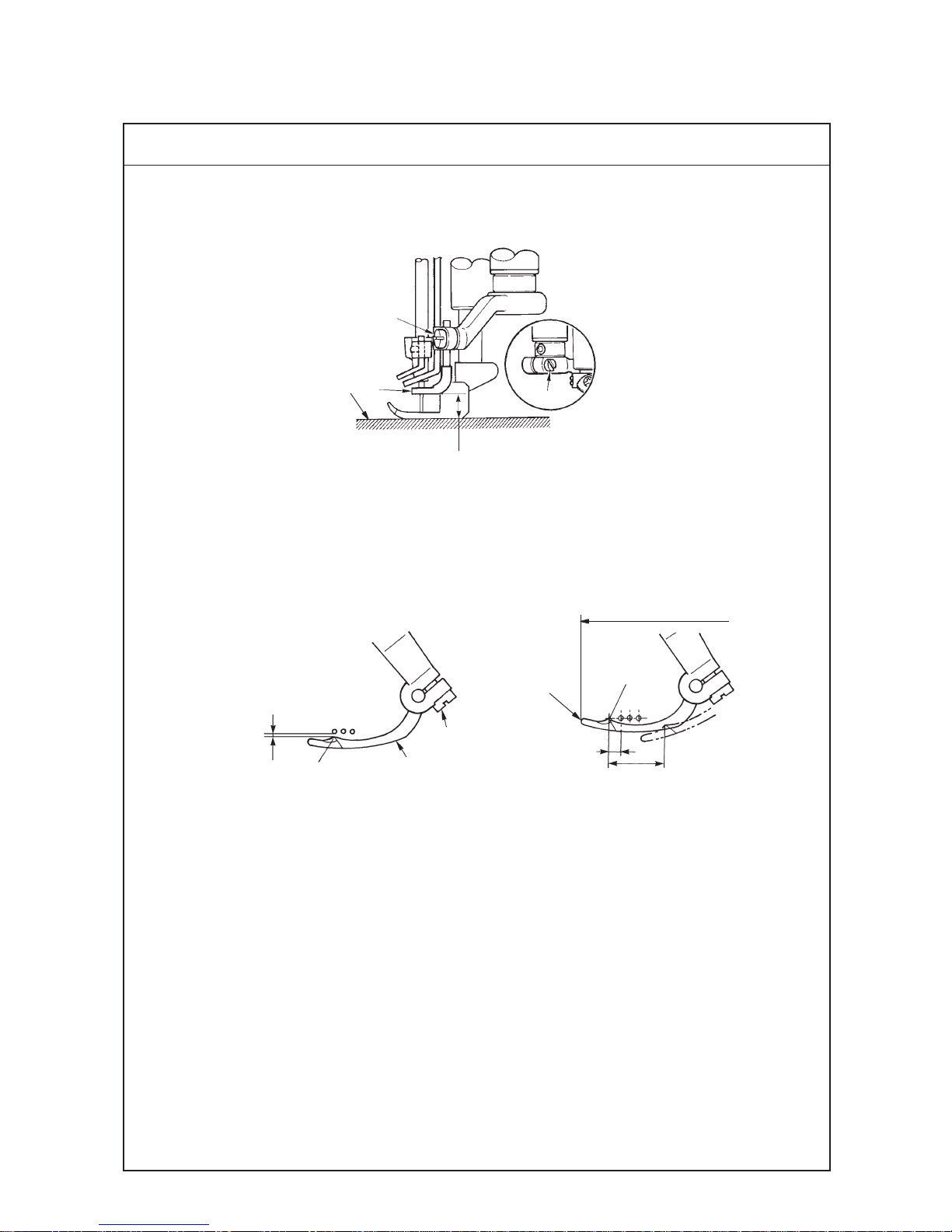
(15) Adjusting the presser foot
1. Height of the presser foot
Height of the presser foot has to be the position the presser foot does not come in contact with other components
at the position where lifter lever 1 is lowered and comes in contact with height adjustment screw 3.
1
2
3
Dimension A
8 mm in case of needle gauge 5.6 mm without top covering
5 mm in case of needle gauge 5.6 mm with top covering
2. Position of the thrust collar
(1) Clearance provided between thrust collar 5 and presser shaft bushing 4 is 0.1 mm at the position where lifter
lever 1 is lowered and comes in contact with height adjustment screw 3.
3. Position of the lifter connecting plate
(1) Adjust the clearance provided between lifter connecting plate 6 and hinge screw 7 to 0.5 mm when the presser
foot is lowered in the state that the feed dog comes down below the throat plate.
(2) Adjust so that the needle enters in the center of needle entry of the presser foot and fix the presser foot with
setscrew 8 in the presser bracket.
7
6
0.5mm
0.1mm
A
4
5
8
9
Throat plate
Center of needle entry
Page 45

–42 –
Standard Adjustment Results of lmproper Adjustment
1. Adjusting the height of the presser foot
Loosen adjustment nut 2. Lower lifter lever 1, adjust height
adjustment screw 3, and fix nut 2 at the position where the presser
foot does not come in contact with other components.
2. Adjusting the thrust collar
Loosen setscrew 9 in the thrust collar and adjust the clearance.
When the height of the presser foot is changed, Be sure to perform
the adjustment of the clearance of thrust collar 5 and check the
clearance.
3. Adjusting the lifter connecting plate
For the adjustment of the clearance provided between lifter
connecting plate 6 and hinge screw 7, loosen setscrew !0 in the
liftrer lever shaft when the feed dog lowers from the top surface of
the throat plate and the bottom face of the presser foot comes in
close contact with the throat plate.
™ When the position of the presser foot
is too high, it comes in contact with
the spreader, and breakage, stitch
skipping, etc. will be caused.
In addition, the needle tip comes out
from the sole of the presser foot. As a
result, sewing material is damaged or
needle breakage will be caused.
™ In case the clearance of thrust collar
5 is large, when the presser foot gets
over the overlapped section, the
presser foot comes in contact with
other components and will cause the
damage.
™ When replacing the presser foot due
to the replacement of the gauge or the
like, check the clearance provided
between thrust collar 5 and lifter
connecting plate 6.
™ When the clearance of lifter
connecting plate 6 does not exist, not
only feed force is reduced but also
components are led to breakage since
the presser foot does not come down
to the top surface of the throat plate
when the feed dog comes down from
the top surface of the throat plate.
™ When adjusting the lever shaft, adjust
the height of lifter lever 1.
!0
Page 46

–43 –
Standard Adjustment
(16) Adjusting the micro-lifter
1. Micro-lifter
Adjust the micro-lifter in accordance with sewing conditions for use.
Major applicable process
1. When twist occurs in the hemming bottom process.
2. When tape is twisted in collarette.
3
2
1
Down
Up
Page 47

–44 –
Standard Adjustment Results of lmproper Adjustment
1. Adjusting the micro-lifter
(1) When micro-lifter knob 1 is turned counterclockwise, micro-lifter
stopper 2 lowere and comes in contact with presser lifting lever 3.
Then the pressr foot goes up.
Adjust the height accordance with the sewing conditions.
(2) When micro-lifter knob 1 is turned clockwise, micro-lifter stopper
2 is raisedand comes in contact with presser lifting lever 3. Then
the presser foot comes down.
(Caution) When the micro-lifter is not used, turn clockwise mocro-
lifter knob 1 and fix micro-lifter stopper 2 at the highest
position.
Page 48

–45 –
Standard Adjustment
(17) Adjusting the looper thread cam
1. Adjust so that thread comes off from the highest place of looper thread cam 2 when needles come down and the
top end of left needle 3 aligns with the bottom surface of looper 4. Then tighten setscrews 1 to fix the looper
thread cam.
2. Preventing thread winding around the looper thread cam
Adjust the clearance provided between the top end of section A of looper thread winding prevention plate 5 and
the edge of looper thread cam 2 to approximately 0 to 0.3 mm (the plate should not come in contact with looper
thread cam 2).
Theread
3
4
2
1
To align
7
6
5
5
2
A
Page 49

–46 –
Standard Adjustment Results of lmproper Adjustment
1. Loosen setscrews 1 in the looper thread cam 2 and adjust while
checking that looper thread comes off from the periphery of the
looper thread cam.
(Caution) When setscrews 1 in the looper thread cam are loosened,
looper thread cam 2 moves in the shaft direction as well.
Assemble so that the clearances provided between the
cam and the thread guide are equal.
2. Adjusting the looper thread winding prevention plate
Adjust the clearance provided between the top end of section A of
looper thread winding prevention plate 5 and the edge of looper
thread cam 2 to approximately 0 to 0.3 mm (looper thread winding
prevention plate 5 has a slot at the section of setscrew 6 and
moves as if it rotates making setscrew 7 as the center), and tighten
setscrews 6 and 7 to fix the looper thread winding prevention
plate.
™ When the position of looper thread
cam 2 slips greatly out of position,
stitch skipping or defect of thread
tightness on the back of the looper 4
is apt to occur.
™ It is effective to adjust as narrow as
possible the clearance provided
between the top end of click section
(section A) of looper thread winding
prevention plate 5 and the edge of
looper thread cam 2. However, when
making them come too near and come
in contact with each other, looper
thread cam 2 is scratched and
winding is caused by this adjustmrent,
instead.
Equal clearances
Page 50

–47 –
Standard Adjustment
1. Changing the needle bar stroke (31 mm 33 mm)
Needle bar stroke is 31 mm in the state that notch mark 4 on the edge of the eccentric pin 5 is located on the side
of the center of main shaft (standard delivery adjustment).
At the time of 31 mm
(18) How to change needle bar stroke
Draw out by more than 1 mm.
7
6
At the time of 31 mm
4
6
5
At the time of 33 mm
5
/
Page 51

–48 –
Standard Adjustment Results of lmproper Adjustment
1. Changing the needle bar stroke
(1) Loosen setscrew 6 (remove the rubber plug) in eccentric pin 5.
(2) Draw out eccentric pin 5 by more than 1 mm, turn eccentric pin 5
by 180fl, position notch mark 4 of the eccentric pin away from the
center of main shaft, push the pin, and fix the pin with setscrew 6.
* Position of the notch mark of eccentric pin
At the time of needle bar stroke 31 mm : notch mark is on the side
of the center of main shaft.
At the time of needle bar stroke 33 mm : notch mark is on the side
away from the center of main shaft.
(Caution) There is a groove to fit, when eccentric pin 5 is turned
by 180˚, at the fitting section of eccentric pin 5 and
counter weight 7. After the change, check that the pin
has completely entered the groove. At the same time,
check whether eccentric pin 5 has completely entered
up to the end.
When the pin is excessively pressed, abnormal noise or
worn-up will be caused.
™ In case of the thick materials, the
stroke is changed. However, basically,
use the machine with the standard
stroke.
™ When the needle bar stroke is
increased, needle heat or sewing
trouble mat occur.
™ When the needle bar stroke is
increased, reduse the sewing speed
for use.
Good result is obtained from the
viewpoint of durability.
6
Page 52

–49 –
Standard Adjustment
(18) How to change Needle bar stroke
2. Adjusting the height of the needle bar
When the needle bar stroke is changed, be sure to adjust the height of the needle bar.
1) Adjust clearances C provided between needles 8 and needle holes 9 in the throat plate to equal.
2) Adjust the height of the needle bar so that the top end of the needle eyelet of left needle aligns with the bottom end
pf the looper when the looper moves from the extreme right position to the left and top end D of looper 3 protrudes
by approximately 1 mm from the left end of left needle, remove rubber cap !1 in the face plate, and tighten the
needle bar with setscrew !0 in the needle bar bracket.
Reference : When the needle is in the highest position, height E from top surface A of the throat plate to the top end
of left needle is as shown in the table below.
3. Adjusting the needle guard
A
E
!0
!1
D
3
9
8
C
Unit : mm
2-needle 3-needle
Needle gauge Height of left needle E Needle gauge Height of left needle E
3.2 11.1 – –
4.0 10.7 – –
4.8 10.2 4.8 10.2
5.6 9.9 5.6 9.9
6.4 8.8 6.4 8.8
3
1
1
0 to
0.05 mm
0.1 to 0.2 mm
0 to
0.05 mm
2
B
A
1
Ridge line
Details of section A
Needle eyelet
Page 53

–50 –
Standard Adjustment Results of lmproper Adjustment
(1) Loosen setscrew !0 in the needle bar bracket and adjust the height
of the needle bar.
(2) After adjusting the height of the needle bar, adjust clearances C
provided between needles 8 and needle holes 9 in the throat
plate to equal and fix the needle bar with setscrew !0.
* Refer to 5.- (9) Height of the needle.
1. Standard position of the rear needle guard
It is the standard that the lateral position of rear needle guard 1 is
the position where the rear needle guard receives the needle in the
range of B in the illustration.
2. It is the standard that the ridge line of rear needle guard 1 enters
in the eyelet of right needle (section A) when the needle bar is in
the lowest position.
3. When the top end of looper 3 comes from the extreme right position
to the center of right needle, the clearance provided between the
right needle and the top end of looper 3 becomes 0 to 0.05 mm
and the pressing amount of the top end of the needle becomes 0.1
to 0.2 mm.
It is the standard for the middle needle that when the top end of
looper 3 comes to the center of middle needle, the clearance
provided between middle needle and the top end of looper 3
becomes 0 to 0.05 mm and the pressing amount of the top end of
needle is such an amount that the rear needle guard touches the
middle needle.
* For the details, refer to the standard adjustment procedure in 5.-
(11) Adjusting the needle guard.
™ When the position of the height of the
needle bar is excessively different,
stitch skipping, needle breakage,
thread breakage, etc. will be caused.
™ When the adjustment value is
excessively different from the specified
value, needle breakage or stitch
skipping will be caused.
Page 54

–51 –
Standard Adjustment
(19) How to change the spreader
1. Changing the spreader
When the needle bar stroke is changed, be sure to perform the adjustment of (6) -1. the height of the spreader.
(1). Height from the top surface of throat plate 2 to spreader 1 is 10.0 to 10.5 mm.
(2). Clearance provided between spreader 1 and spreader thread guide 2 is 0.4 to 1.0 mm.
(3). Clearance provided between spreader thread guide 3 and needle clamp thread guide 4 is 0.8 to 1.2 mm.
0.8 to 1.2 mm
0.4 to 1.0 mm
10.0 to 10.5 mm
4
3
1
2
Page 55

–52 –
Standard Adjustment Results of lmproper Adjustment
1. Refer to (6) Adjusting the spreader.
Page 56

–53 –
Standard Adjustment
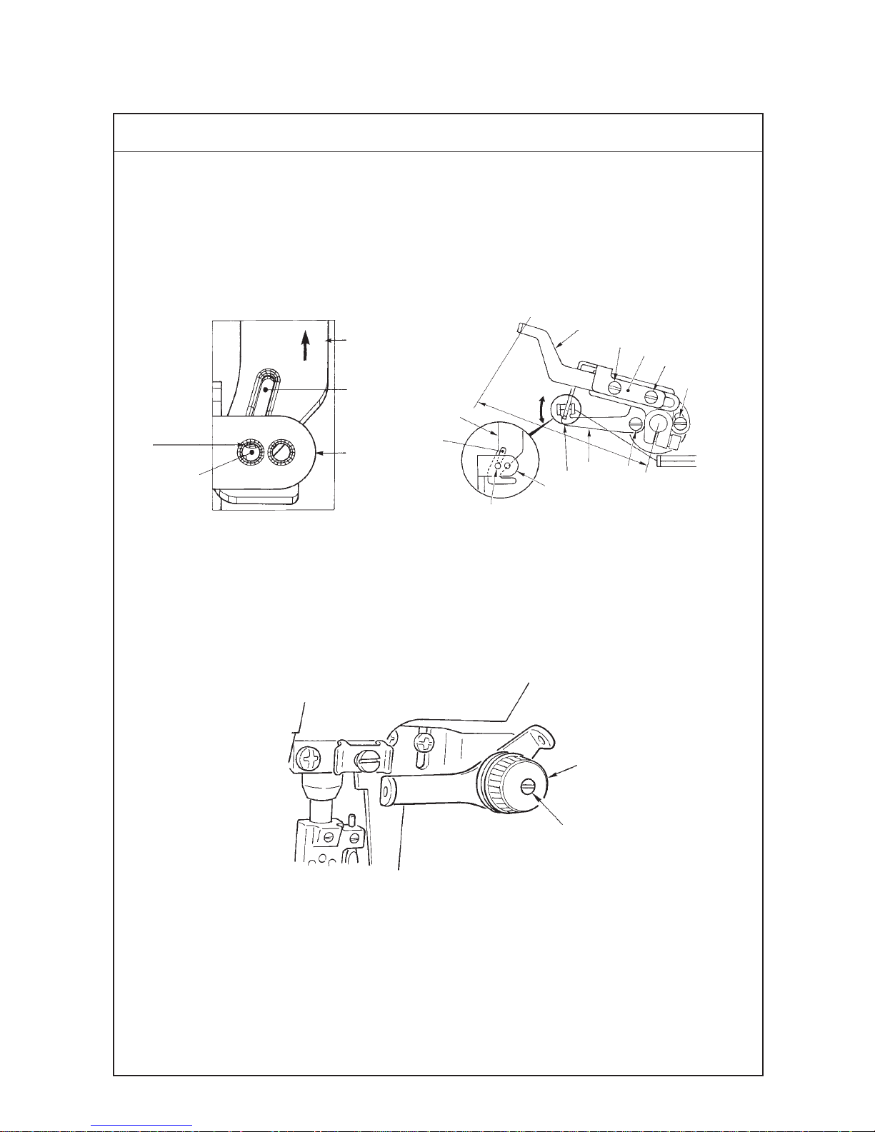
(20) With reagard to lubrication
1. Replacing the oil filter
Normal lubrication cannot be performed if dust collects in
oil filter 1.
Inspect it evry 6 months.
2. Oil circulation identification window
Make sure that lubricating oil rises to oil circulation
identification window 3 during operation.
<When using the sewing machine for the first time>
Lubricating oil has been taken out at the time of delivery.Be
sure to supply lubricating oil before using the sewing machine
for the first time.
• Oil used : JUKI MACHINE OIL 18
(Caution) Do not use oil addition agent sinse deterioration
of lubricating oil or machine trouble will be caused.
Remove oil hole cap !1 on which “OIL” is indicated and fill
the oil reservoir with lubricating oil up to the level between
the upper and lower engraved marker lines of oil gauge !0.
<Checking before using the sewing machine>
1) Check oil gauge !0 and make sure that lubricating oil level
is between the upper and lower two lines. When lubricating
oil level lowers below the lower line, supply lubricating oil.
2) Make sure that lubricating oil comes out from the nozzle of
oil circulation identification window 4 when rotating the
sewing machine. When lubricating oil does not come
out,perform “Inspecting and replacing the oil filter 1”.
6
5
6
2
1
3
!0
!1
4
Lubrication
Page 57

–54 –
Standard Adjustment Results of lmproper Adjustment
1. Inspection and replacement
Loosen setscrews 3 in the oil filter cap and remove oil filter cap 2.
Draw out oil filter 1 to inspect it. When it is clogged with dust,
replace it with a new one.
After the replacement, fix oil filter cap 2 with setscrews 1 in the oil
filter cap.
(Caution) When removing the oil filter cap 2, lubricating oil
collected in oil filter 1 will leak out. So, be careful.
2. Oil circulation identification
(1) In case the oil does not come out from oil circulation identification
window 4 even when oil filter 1 is replaced with a new one, remove
six setscrews 6 in the oil pan, remove oil pan 5, and tilt the machine
head to the rear up to the position where pipe connecting joint screw
9 can be removed.
(2) Oil sucked up from gear pump 7 passes oil pipe 8 and enters oil filter 1
from pipe connecting joint screw 9. When the lubricatin oil does not rise
to oil circulation identifacation window 4, The hole in pipe connecting
joint screw 9 may be clogged with dust. So, check it.
(Caution) When there is any foreign material in oil pan 5, remove it.
™ In case oil cannot be observed from
oil circulation identification window 4
even when the sewing speed is 2,500
rpm or over, the machine will be in
danger of seizure if the operation is
continued.
7
9
8
Page 58

–55 –
1. When SC-380 is used, install the motor referring to the Instruction Manual for SC-380.
2. To use SC-380 with MF-7700, it is necessary to set the followings after set-up of SC-380.
(Caution) When MF is selected in case of machine model selection, change the direction of rotation since the
direction of rotation of MF-7700 becomes reverse. In addition, there is the possibility that the pulley
rotates up to the home position at the time of turning ON the power.
™ Change over the setting of SC-380 to MF-7700
(When changing, refer to the Instruction Manual for SC-380 as well)
1
2
3
4
5
* Program mode (2) Model selection
Select MF with
+ [C] + [D], and keep pressing [D] for more than two
seconds to return to the normal mode. (When the thread trimmer is not
installed, proceed to 2 C mode Thread trimmer safety switch release to
release the safety switch since LED.M does not rotate.)
* C mode Thread trimmer safety switch release
(Setting when thread trimmer is not used)
IA S6 is displayed with
+ [C]. Set IA S6 to IA NO.
Screen returns to the normal mode with
+ .
* Prohibition function of J mode direction of rotation changeover
+ .+ A + B CWC ON / OFF
Screen returns to the normal mode with
+ .
* Change of the direction of rotation
Set the direction of rotation to the clockwise rotation with + [M].
* Operating function of P mode when power is turned ON
When 1-position is set :
+ P1P ON / OFF
When 2-position is set :
+ P2P ON / OFF
Screen returns to the normal mode with
+ .
(21) Adjusting and setting SC-380
Page 59

–56 –
3. Adjusting the position detector of SC-380
1) When using the position detector for MF-7700,
change DOWN position of the needle and adjust
DOWN position of the position detector so that the
needle stops after the top end of looper B has
scooped left needle thread A as shown in the figure.
4. Adjusting procedure
In the state that the position detector is actually
installed on the sewing machine, adjust the stopping
position.
1) Temporarily install detector 1 onto the lower pulley
with setscrews 2.
2) Wind the ground wire (green/yellow) around the cord
of detector 1, connect the ground wire to the ground
mark in the rear of the sewing machine head, and fix
the cord of the detector at the position in the figure
with cord clamp 6 and setscrew 7 supplied with the
machine.
3) Connect the connector of detector 1 to the connector
of detector of SC-380 control box. Turn ON the power,
set the sewing machine controller to 1 position setting
(needle UP position stop) and lightly depress the pedal
to operate the sewing machine by 2 to 3 stitches. Then
turn OFF the power at the position where the sewing
machine has stopped. Loosen setscrews 2 in detector
1, turn the upper pulley with joint 4 fixed, and adjust
the stopping position.
Fix detector 1 with setscrews 2.
4) Remove the cover of detector 1 and adjust the red
mark ▼ 5 on the outside of DOWN position detector
plate 3 to 11 to 12 of the scale (inside DOWN position
detector plate).
5) After adjustment of stopping position, replace the cover
of detector 1.
6) Turn ON the power again, and set the sewing machine
controller to 2 position setting.
B
A
1
2
4
6
7
5
13
Page 60

– 57 –
6. TROUBLES AND CORRECTIVE MEASURES
Troubles Cause (1) Cause (2) Corrective measures
1. Thread breakage
2. Looper thread breakage
Refer to threading diagram.
Remove the flaw, burr etc. and process the thread guide
finish. However, replace such important parts as looper or
throat plate etc. with the new part because their shape is
changed by being processed.
In case needle exchanger, or looper needle guard is worn
out, replace it with the new part.
Replace it with an appropriate needle.
Use thinner needle. Reduce the sewing speed. Use silicon
oil lubricant device.
Replace it with the thread of good quality.
Reduce thread tension. needle thread guide rod is positioned
too high making the thread tension too strong.
Mount it in the correct position.
Remove the flaw, burr etc.
Remove the flaw, burr etc. and process the thread guide
finish. However, replace such parts as looper with the new
part because its shape is changed by being processed.
Refer to the standard adjustment figures.
Reduce the thread tension while checking to see the tension
balance against the needle thread, top covering thread.
1-1) Threading
1-2) Thread path
1-3) Needle guard
1-4) Needle
1-5) Needle heat
1-6) Thread
1-7) Thread tension
1-8) Interference
1-9) Chain-off thread defect
2-1) Thread guide
2-2) Looper thread cam adjustment
2-3) Thread tension
To the next page
1-A) Thread caught in thread guide, Incorrect
threading
2-A) Resistance produced by flaw, burr, rust etc.
around needle entry of throat plate, stitch
tongue, looper, spreader, needle thread takeup auxiliary thread tention adjustment, needle
guide, thread tension disc etc.
3-A) Strong contact of needle against needle
guard produces a sharp edge in needle
guard resulting in thread breakage.
4-A) Too thin needle for the thread used
5-A) Needle is heated depending on fabric
type, number of fabrics, sewing speed
resulting in thread breakage.
6-A) Poor quality and weakness of thread
7-A) Too strong thread tension
8-A) Interference with feed dog, throat plate due
to the incorrect mounting height of looper
9-A) Flaw produced in stitch tongue in throat
plate, feed dog, tongue in presser foot,
underside in presser foot
1-A) Resistance produced by flaw, burr, rust
etc. in stitch tongue in throat plate, looper,
looper thread cam, thread guide, thread
tension disc
2-A) Excessive tension applied due to the
incorrect position of looper thread cam
timing, thread guide
3-A) Too strong tension of looper thread
Page 61

– 58 –
Troubles Cause (1) Cause (2) Corrective measures
From the previous page
3. Needle breakage
4. Worn out needle point
2-4) Thread
2-5) Looper avoid
2-6) Needle heat
3-1) Needle entry
3-2) Spreader
3-3) Interference of looper with
scooping movement of needle
3-4) Needle guard
3-5) Needle thickness No.
3-6) Thread tension
3-7) Feed height, Needle height
4-1) Needle guard
4-2) Interference with looper
4-A) Poor quality and weakness of thread
5-A) Too strong contact of looper back with
needle resulting in thread breakage
6-A) In case needle heat is generated looper
thread’s contact with needle causes
thread breakage, specially at the time
machine is at rest.
1-A) Needle hits the throat plate or presser foot
because the needle entry is not correctly
positioned for the plate or foot.
2-A) Too little clearance between spreader
and needle
3-A) Needle hits looper resulting in needle
breakage.
4-A) Too strong contact against needle guard
or needle point hits needle guard due to
incorrect position.
5-A) Too thin needle for fabric used
6-A) Needle thread tension is too strong.
7-A) Feed dog is too high or needle height is
too low resulting in needle breakage due
to needle swerve.
1-A) Incorrect height or incorrect
position, front and rear
2-A) Moving amount, front and rear is ill
balanced.
Replace it with good quality of thread.
Adjust longitudinal momentum of the looper and make the looper contact
the needle at 1/3 height from the bottom surface of the back of looper.
Refer to needle heat in needle breakage
Align the needle entry to the needle.
Refer to the standard adjustment figures.
Make adjustment so that looper does not hit the looper. For
the correction of the contact at looper’s back, adjust the
moving amount, front and rear.
Refer to the standard adjustment figures.
Use thicker needle.
Reduce the needle thread tension.
Refer to the standard adjustment figures.
Check to see the height of needle guard and clearance
between needle guard and needle.
Adjust moving amount, front and rear and correct the incorrect
position of looper’s back and the contact when it returns.
Page 62

– 59 –
A-1) Incorrect shape of pointed end of
looper disables scooping a loop.
B-1) Needle bend, incorrect needle
mounting direction, wrong needle
C-1) Not used.
D-1) Too high
E-1) Needle bar position is too high.
F-1) Incorrect threading
G-1) Not used.
H-1) Spreader thread tension is too strong.
I-1) Stitch skip occurs before thread
breakage produced by needle heat.
J-1) Incorrect clearance adjustment,
incorrect returning amount adjustment
K-1) Incorrect contact amount, incorrect
height
A-1) Incorrect shape of pointed end of
looper disables scooping a loop.
B-1) Needle bend, incorrect needle
mounting direction, wrong needle
C-1) Being used.
D-1) Height is too low.
E-1) Needle bar height is too low.
F-1) Incorrect threading
Replace it with the genuine part.
Replace the needle with new one, Correct the
mounting direction, Use UY128GAS.
Use nipper.
Correct the height to appropriate height.
Refer to the standard adjustment figures.
Refer to threading diagram.
Use needle guard.
Reduce the tension.
Same described in page “ Thread breakage by
needle heat”
Refer to standard adjustment.
Refer to the standard adjustment figures.
Replace it with the genuine part.
Replace the needle with new one, Correct the
mounting direction, Use UY128GAS.
Do not use nipper.
Correct height position to appropriate height.
Refer to the standard adjustment figures.
Refer to threading diagram.
1-A) Looper
1-B) Needle
1-C)
Auxiliary thread tention adjustment
1-D) Needle thread guide rod
1-E) Needle height
1-F) Threading
1-G) Needle guard
1-H) Spreader
1-I) Needle heat
1-J) Looper adjustment
1-K)
Needle guard, front and rear
2-A) Looper
2-B) Needle
2-C)
Auxiliary thread tention adjustment
2-D) Needle thread guide rod
2-E) Needle height
2-F) Threading
Troubles (1) Troubles (2) Cause (1) Cause (2) Corrective measures
5. Stitch skipping 5-1) Looper does not scoop
the right needle thread.
5-2) Looper does not scoop
the middle needle thread.
To the next pageTo the next page
Left Right Left Right
Left Right Left Right
Page 63

– 60 –
G-1) Being used.
H-1) Spreader thread tension is too strong.
I-1) Stitch skip occurs before thread
breakage produced by needle heat.
J-1) Incorrect clearance adjustment,
incorrect returning amount adjustment
K-1) Incorrect contact amount, incorrect
height
A-1) Incorrect shape of pointed end of
looper disables scooping a loop.
B-1) Needle bend, incorrect needle
mounting direction, wrong needle
C-1) Being used.
D-1) Height is too low.
E-1) Height is too low.
F-1) Incorrect threading
G-1) Being used.
H-1) Too near to the left needle
I-1) Stitch skip occurs before thread
breakage produced by needle heat.
J-1) Incorrect clearance adjustment,
incorrect returning amount
K-1) Incorrect contact amount, incorrect
height
Do not use.
Reduce the tension.
Same described in page “Thread breakage by
needle heat”
Refer to the standard adjustment figures.
Refer to the standard adjustment figures.
Replace it with the genuine part.
Replace the needle with new one, Correct the
mounting direction, Use UY128GAS.
Do not use nipper.
Correct height position to appropriate height.
Refer to standard adjustment.
Refer to threading diagram.
Do not use.
Refer to the standard adjustment figures.
Same described in page “Thread breakage by
needle heat”
Refer to the standard adjustment figures.
Refer to the standard adjustment figures.
2-G) Needle thread guard
2-H) Spreader
2-I) Needle heat
2-J) Looper adjustment
2-K)
Needle guard, front and rear
3-A) Looper
3-B) Needle
3-C)
Auxiliary thread tention adjustment
3-D) Needle thread guide rod
3-E) Needle height
3-F) Threading
3-G) Needle guard
3-H) Spreader
3-I) Needle heat
3-J) Looper adjustment
3-K)
Needle guard, front and rear
Troubles (1) Troubles (2) Cause (1) Cause (2) Corrective measures
From the previous pageFrom the previous page
To the next page
Left Right Left Right
5-3) Looper does not scoop
the left needle thread.
Page 64

– 61 –
A-1) Ventral shape is incorrect.
B-1) Needle bend
C-1) Needle bar position is too high.
D-1) Incorrect threading
E-1) Incorrect clearance adjustment,
incorrect returning amount
F-1) Tension is too weak.
G-1) Looper thread cam timing is too
Replace it with the genuine part.
Replace the needle with the new one.
Refer to the standard adjustment figures.
Refer to threading diagram.
Refer to the standard adjustment figures.
Increase tension.
Refer to the standard adjustment figures.
4-A) Looper
4-B) Needle
4-C) Needle height
4-D) Threading
4-E) Looper adjustment
4-F) Looper thread tension
4-G)
Looper thread cam timing
Troubles (1) Troubles (2) Cause (1) Cause (2) Corrective measures
From the previous page
To the next page
5-4) Needle does not scoop the
looper thread.
(Triangle stitch skip)
Middle needle Left needle
Stitch skip by middle needle
Slack of looper thread
Stitch skip by left needle
Slack of looper thread
Page 65

– 62 –
A-1) Incorrect shape of pointed end of
spreader disables scooping a thread.
B-1) Needle bend, improper needle
attaching and wrong needle
C-1) Incorrect height, protruding amount,
longitudinal position, stroke and timing
D-1) Incorrect height, position
E-1) Needle bar position is too low.
F-1) Incorrect threading
G-1) Incorrect height, position, front and
rear
H-1) Spreader thread tension is too weak.
I-1) Incorrect drawing-in amount of thread
Replace it with the genuine part.
Replace the needle with the new one, Use UY128GAS.
Refer to the standard adjustment figures.
Refer to the standard adjustment figures.
Refer to the standard adjustment figures.
Refer to threading diagram.
Refer to the standard adjustment figures.
Increase tension.
Refer to the standard adjustment figures.
5-A) Spreader
5-B) Needle
5-C) Spreader adjustment
5-D) Spreader thread guide
5-E) Needle height
5-F) Threading
5-G) Needle clamp thread
guide
5-H) Spreader thread tension
5-I) Spreader take-up thread
drawing-in amount
Troubles (1) Troubles (2) Cause (1) Cause (2) Corrective measures
From the previous page
To the next page
5-5) Skipping in top cover
stitch (right)
Correct
Incorrect
Skipping in top covering stitch by right needle
Simultaneous skip by left and middle needle
Failure of
catching thread
Right needle
Right needle
Correct
Incorrect
Skipping in top covering stitch by right needle
Right needle does not stride over the top
covering thread.
MiddleLeft Right
Spreader does not fetch the top covering thread.
Page 66

– 63 –
A-1) Needle bend, improper needle
attaching and wrong needle
B-1)
Incorrect height, protruding amount,
longitudinal position, stroke and timing
C-1) Incorrect needle bar position
D-1) Incorrect threading
E-1)
Spreader thread tension is too weak.
F-1)
Incorrect drawing-in amount of thread
G-1) Incorrect height and position
Replace the needle with the new one, Use UY128GAS.
Refer to the standard adjustment figures.
Refer to the standard adjustment figures.
Refer to threading diagram.
Increase tension.
Refer to the standard adjustment figures.
Refer to the standard adjustment figures.
6-A) Needle
6-B) Spreader adjustment
6-C) Needle height
6-D) Threading
6-E) Spreader thread tension
6-F) Spreader pull-off
6-G) Spreader thread guide
Troubles (1) Troubles (2) Cause (1) Cause (2) Corrective measures
From the previous page
To the next page
5-6) Skipping in top covering
stitch (Middle)
Correct
Middle
needle
Middle
needle
Incorrect
Skipping in top covering stitch by middle needle
Middle needle does not scoop top covering thread.
Left Middle Right
Correct Incorrect
Middle
needle
Middle
needle
Middle needle strides over top covering thread sometimes.
Page 67

– 64 –
A-1) Incorrect shape of pointed end
disables scooping a thread.
B-1) Needle bend, improper needle
attaching and wrong needle
C-1) Incorrect height, protruding
amount, position, front and rear
D-1) Incorrect height and position
E-1) Needle bar position is too low.
F-1) Incorrect threading
G-1) Spreader tension is too weak.
H-1)
Incorrect drawing-in amount of thread
Replace it with the genuine part.
Replace needle with new one, Use UY128GAS.
Refer to the standard adjustment figures.
Refer to the standard adjustment figures.
Refer to the standard adjustment figures.
Refer to threading diagram.
Increase tension.
Refer to the standard adjustment figures.
7-A) Spreader
7-B) Needle
7-C) Spreader adjustment
7-D) Spreader thread guide
7-E) Needle height
7-F) Threading
7-G) Spreader thread tension
7-H)
Spreader pull-off
drawing-in amount of thread
From the previous page
To the next page
5-7) Skipping in top
covering stitch (Left)
Correct
Incorrect
Skipping in top covering stitch by left needle
Left needle does not scoop top covering thread.
Left
needle
Left
needle
Troubles (1) Troubles (2) Cause (1) Cause (2) Corrective measures
Page 68

– 65 –
A-1) Needle bend, improper needle
attaching and wrong needle
B-1) Needle bar position is too high.
C-1) Incorrect threading
D-1) R of stitch tongue in throat plate is
too small.
Incorrect polishing
E-1) R of looper’s ventral section is too
large and ridgeline is not tense, for
which needle thread is likely to slip
from looper.
F-1) Too little contact amount between
looper’s back and needle
G-1) Thread tension is too weak.
H-1) Low position of thread guard
results in too large needle thread loop.
I-1) Thread guard position is too high.
J-1) Use of nipper could easily
generate this trouble.
K-1) Drawing-in amount of looper
thread is too much.
Replace the needle with the new one, Use UY128GAS.
Refer to the standard adjustment figures.
Refer to threading diagram.
Increase R. Polish correctly.
Replace it with the genuine part.
Refer to the standard adjustment figures.
Increase tension.
Lift thread guide position.
Refer to the standard adjustment figures.
Do not use nipper.
Reduce drawing-in amount of thread.
8-A) Needle
8-B) Needle height
8-C) Threading
8-D) Throat plate
8-E) Looper
8-F) Looper adjustment
8-G) Thread tension
8-H) Needle thread guide rod
8-I) Thread guard position
8-J)
Auxiliary thread tention adjustment
8-K) Looper thread cam
thread guide position
Troubles (1) Troubles (2) Cause (1) Cause (2) Corrective measures
From the previous page
To the next page
5-8) Single chain thread cast-
off (Right, Middle, Left)
R
Page 69

– 66 –
One chain stitch by right needle
One chain stitch by middle needle
One chain stitch by left needle
Right needle thread miss
Middle needle thread miss
Page 70

– 67 –
A-1)
R of stitch tongue in throat plate is
too large. Stitch tongue is too short.
B-1) Worn out needle point, needle
bend, wrong needle
C-1) Flaw in looper’s ventral section,
incorrect polishing
D-1) Needle bar position is too low.
E-1) Incorrect threading
F-1) Tension is too weak.
G-1) Substandard lower positioning of
thread guide
H-1) Use of nipper is likely to generate
this trouble.
Replace it with the genuine part.
Replace needle with new one, Use UY128GAS.
Replace the looper when modified or its shape is
changed too much.
Refer to the standard adjustment figures.
Refer to threading diagram.
Increase tension.
Adjust the thread guide position upward.
Do not use nipper.
9-A) Throat plate
9-B) Needle
9-C) Looper
9-D) Needle height
9-E) Threading
9-F) Needle thread tension
9-G) Needle thread guide rod
9-H)
Auxiliary thread tention adjustment
Troubles (1) Troubles (2) Cause (1) Cause (2) Corrective measures
From the previous page
To the next page
5-9) Double bonding stitch
(Middle, Left)
R Length of stitch tongue
Right needle enters middle
needle loop.
Middle needle enters left
needle loop.
Page 71

– 68 –
A-1) Incorrect polishing
B-1) Stroke of spreader is too large.
C-1) Worn out looper’s pointed end
and incorrect polishing
D-1) Drawing-in amount of top
covering thread is too much.
E-1) Needle thread tension is too weak.
F-1) Incorrect threading
G-1) Thread tension is too weak.
H-1) Drawing-in amount of looper
thread is too much.
A-1) Incorrect polishing, Too long
stitch tongue
B-1) Worn out needle point, needle
bend, wrong needle
C-1) Worn out looper’s pointed end,
incorrect polishing
D-1) Needle bar position is too low.
E-1) Incorrect threading
F-1) Tension is too weak.
G-1) Either the position of thread
guide is too low or too high.
H-1) Tension is too strong.
I-1) Drawing-in amount of looper
thread is too little.
Polish correctly.
Refer to the standard adjustment figures.
Replace the looper when modified or its shape is
changed too much.
Refer to the standard adjustment figures.
Increase tension.
Refer to threading diagram.
Increase tension.
Reduce drawing-in amount of thread.
Correct or replace part.
Replace needle with new one, Use UY128GAS.
Replace the looper when modified or its shape is
changed too much.
Refer to the standard adjustment figures.
Refer to threading diagram.
Increase tension.
Refer to the standard adjustment figures.
Reduce tension.
Increase drawing-in amount of thread.
Troubles (1) Troubles (2) Cause (1) Cause (2) Corrective measures
From the previous page
To the next page
5-10) Irregular stitches
(Left, Middle, Right)
5-11) Ill-tensed seam
10-A) Throat plate
10-B) Spreader adjustment
10-C) Looper
10-D)
Top covering thread take-up
10-E) Needle thread tension
10-F) Threading
10-G)
Top covering thread tension
10-H) Looper thread cam
thread guide position
11-A) Throat plate
11-B) Needle
11-C) Looper
11-D) Needle height
11-E) Threading
11-F) Needle thread tension
11-G) Needle thread guide rod
11-H) Looper thread tension
11-I) Looper thread cam
thread guide position
Page 72

– 69 –
A-1) Flaw in pointed end of spreader
obstructs smooth thread threading.
B-1) Spreader stroke is too large.
C-1) Flaw, burr in slot
D-1) Drawing-in amount of top covering
thread is too much or too little.
E-1) Needle thread tension is too weak.
F-1) Incorrect threading
G-1) 1st thread tension is too weak.
H-1) Drawing-in amount of looper
thread is too much.
I-1) Thread threading is not smooth due
to incorrect shape of stitch tongue.
A-1) Stitch tongue is too short.
B-1) Incorrect threading
C-1) Tension is too strong.
D-1) Tension is too strong.
E-1) Drawing-in amount of upper thread
is too little.
Replace when modified or its shape is changed too
much.
Refer to the standard adjustment figures.
Replace when modified or its shape is changed too
much.
Refer to the standard adjustment figures.
Increase tension.
Refer to threading diagram.
Increase tension.
Reduce drawing-in amount of thread.
Replace when modified or its shape is changed too
much.
Use throat plate provided with long stitch tongue.
Refer to threading diagram.
Reduce tension.
Reduce tension.
Increase drawing-in amount.
Troubles (1) Troubles (2) Cause (1) Cause (2) Corrective measures
From the previous page
To the next page
5-12) Irregular stitches in top
covering stitches
5-13) Bulge
12-A) Spreader
12-B) Spreader adjustment
12-C) Thread guide
12-D)
Top covering thread take-up
12-E) Needle thread tension
12-F) Threading
12-G)
Top covering thread tension
12-H) Looper thread cam
thread guide position
12-I)
Stitch tongue of presser foot
13-A) Throat plate
13-B) Threading
13-C) Needle thread tension
13-D) Looper thread tension
13-E) Looper thread cam
thread guide position
Flaw
Page 73

– 70 –
A-1) Thread threading is not smooth due
to incorrect polishing in stitch tongue.
B-1) Stitch skip in top covering stitch
due to incorrect adjustment
C-1) Stitch skip due to incorrect adjustment
D-1) Drawing-in amount of top covering
thread is too much or too little.
E-1) Needle thread tension is too weak.
F-1) Incorrect threading
G-1) 1st thread tension is too weak.
H-1)
Thread threading is not smooth due
to incorrect shape of stitch tongue.
I-1) Worn out needle point, needle
bend, wrong needle
J-1) Flaw on surface in feed dog
Replace when polished or its shape is changed too
much.
Refer to the standard adjustment figures.
Refer to the standard adjustment figures.
Refer to the standard adjustment figures.
Increase tension.
Refer to threading diagram.
Increase tension.
Replace when its shape is modified or changed too
much.
Replace needle with new one, Use UY128GAS.
Modify or replace
Troubles (1) Troubles (2) Cause (1) Cause (2) Corrective measures
From the previous page
5-14) Defective chain-off thread
(with top covering stitch)
14-A) Throat plate
14-B) Spreader adjustment
14-C) Looper adjustment
14-D)
Top covering thread take-up
14-E) Needle thread tension
14-F) Threading
14-G)
Top covering thread tension
14-H)
Stitch tongue of presser foot
14-I) Needle
14-J) Feed dog
Page 74

– 71 –
7.DRAWING OF TABLE (SEMI-SUBMERGED TYPE)
Table Part No. : 13349204
A 4- ø 3.4 on the bottom surface, depth 20
(Drill a hole at the time of set-up.)
B 4-10.5 hole, depth 26, spot facing depth 3.5
C 2- ø 3.4 on the bottom surface, depth 10
(Drill a hole at the time of set-up.)
D Y-Y (3-places) E Z-Z (4-places)
F Drilled hole 17 G JUKI logo type
H Installing position of stopper for drawer
(on the reverse side)
E
130
810
159
77.5
75
R30
248 76.5
46
233.5
506.5
99.5
46
23
326.5
57
251.5
23
23
115
40
10
ø 26
ø 8.5
(ø 26)
(ø 10.5)
30˚
(3.5)
X-X
D
360
570
60
(90)
F
A
C
66
33
Y
Y
3
R10
R10
X
X
57
R21
ø48
439
B
192
120
23
21
11
40
R10
R21
R10
R21
R21
R10
R10
R10
R10
50
ZZ
R21
R21
R10
22
21
40
R30
272
R10
(2)
5
180.5
R10
R10
1
1200
H
R30
100
390
10
R10
R10
15
40
21 50
G
R6
R30
R6
± 1
± 1
± 1
± 1
± 1
± 1
± 1
Page 75

Please do not hesitate to contact our distributors or agents in your area for further information when necessary.
* The description covered in this engineer's manual is subject to change for improvement of the
commodity without notice.
03 · 11 Printed in Japan (E)
R
INTERNATIONAL SALES H.Q.
8-2-1, KOKURYO-CHO,
CHOFU-SHI, TOKYO 182-8655, JAPAN
PHONE : (81)3-3430-4001 to 4005
FAX : (81)3-3430-4909 • 4914 • 4984
TELEX : J22967
Copyright c 2003 JUKI CORPORATION.
All rights reserved throughout the world.
 Loading...