

Page 1
Semi-dry head, Flat-bed Top and Bottom Coverstitch Machine
MF-7700D Series
ENGINEER’S MANUAL
®
40084333
No.E386-00
Page 2

PREFACE
This Engineer’s Manual is written for the technical personnel who are responsible for the service and maintenance
of the machine.
The Instruction Manual for these machines intended for the maintenance personnel and operators at an apparel
factory contains operating instructions in detail. And this manual describes "Standard Adjustment", "Adjustment
Procedures", "Results of Improper Adjustment", and other important information which are not covered by the
Instruction Manual.
It is advisable to use the relevant Instruction Manual and Parts List together with this Engineer’s Manual as well as
the MF-7700, SC-500, and SC-510 Series Manuals when carrying out the maintenance of these machines.
In addition, for the motor for the sewing machine with thread trimmer, refer to the separate Instruction Manual or
Engineer’s Manual for the motor. And for the control panel, refer to the Instruction Manual for the control panel.
This manual gives the "Standard Adjustment" on the former page under which the most basic adjustment value is
described, and on the latter page "Results of Improper Adjustment" under which stitching errors and troubles arising
from mechanical failures are described together with the "Adjustment Procedures".
Page 3

CONTENTS
1. SPECIFICATIONS................................................................................................... 1
2. CONFIGURATION OF THE MACHINE COMPONENTS........................................ 2
3. MODEL NUMBERING SYSTEM ............................................................................ 3
(1) MF-7700D Series . ................................................................................................................... 3
(2) MF-7700D Series Thread trimmer.......................................................................................... 4
4. MOTOR PULLEY AND BELT ................................................................................. 5
5. ST ANDARD ADJUSTMENT ................................................................................... 6
(1) Threading the machine head . ............................................................................................... 6
(2) Adjusting the rocking thread take-up ................................................................................... 8
(3) Adjusting the position of the needle thread guide rod ..................................................... 10
(4) Adjusting the position of the thread receiver .................................................................... 12
(5) Adjusting the position of the spreader thread guide and spreader thread take-up....... 14
(6) Adjusting the spreader......................................................................................................... 16
(7) Adjusting the timing relation between the looper and needle bar................................... 20
(8) Returning amount of the looper .......................................................................................... 22
(9) Height of the needle ............................................................................................................. 24
(10)Locus and longitudinal motion of the looper..................................................................... 26
(11)Adjusting the needle guard ................................................................................................. 28
(12)Installing cover of the looper and needle guard after adjusting ...................................... 32
(13)Adjusting the feed dog ......................................................................................................... 34
(14)Adjusting the feed relation .................................................................................................. 40
(15)Adjusting the presser foot ................................................................................................... 42
(16)Adjusting the micro-lifter ..................................................................................................... 44
(17)Adjusting the looper thread cam......................................................................................... 46
(18)With regard to lubrication .................................................................................................... 48
(19)Setting for functions of SC-500 ........................................................................................... 52
(20)Adjusting and setting SC-510 .............................................................................................. 54
(21) MF-7700D/MF-7800D How to use the timing gauge .......................................................... 58
6. E10/MD10.............................................................................................................. 59
(1) Specifications (E10).............................................................................................................. 59
(2) Specifications (MD10) .......................................................................................................... 59
(3) Adjusting the needle guard ................................................................................................. 60
(4) Adjustment of knife .............................................................................................................. 62
(5) Presser adjustments ............................................................................................................ 66
(6) Method of lubrication ........................................................................................................... 68
(7) Adjustment of the amount of feeding ................................................................................. 70
(8) Adjustments for heavy material sewing ............................................................................. 72
(9) Mounting position of the eccentric cam............................................................................. 74
Page 4

7. MF-7724DU10D60 (4 needles)............................................................................. 77
(1) Specifications . ..................................................................................................................... 77
(2) Needle .................................................................................................................................... 77
(3) Standard adjustments .......................................................................................................... 78
1) Needle mounting.............................................................................................................................78
2) Threading the machine head .........................................................................................................80
3) Adjusting the rocking thread take-up ...........................................................................................82
4) Adjusting the position of the needle thread guide rod ............................................................... 84
5) Adjusting the rocking thread take-up thread receiver ................................................................86
6) Adjusting the looper.......................................................................................................................88
7) Adjusting the height of the needle................................................................................................ 88
8) Adjusting the rear needle guard....................................................................................................90
9) Adjusting the looper thread cam...................................................................................................90
10)Installing position of the spreader ................................................................................................92
8. UT31...................................................................................................................... 94
(1) Installation of SC-500 ........................................................................................................... 94
(2) Change of the setting ........................................................................................................... 96
(3) Adjusting the synchronizer ................................................................................................. 98
(4) Installation of SC-510 ......................................................................................................... 100
(5) Adjusting the looper thread trimmer mechanism............................................................ 106
9. UT33.................................................................................................................... 120
(1) Installation of SC-500 ......................................................................................................... 120
(2) Installation of SC-510 ......................................................................................................... 122
(3) Piping of the thread trimmer device ................................................................................. 124
(4) Adjusting the looper thread trimmer mechanism............................................................ 126
(5) Adjusting the top covering thread trimmer mechanism ................................................. 130
(6) Adjusting the air-blow wiper.............................................................................................. 132
10.TC13 (Tape cutter) ............................................................................................. 134
(1) Specifications ..................................................................................................................... 134
(2) Adjustment of knife ............................................................................................................ 136
(3) TC13C .................................................................................................................................. 140
11. OTHER CAUTIONS ............................................................................................ 146
(1) MF-7700D dry section......................................................................................................... 146
(2) Application of appropriate grease .................................................................................... 146
(3) Adhesives application spots ............................................................................................. 148
12.TROUBLES AND CORRECTIVE MEASURES .................................................. 149
13.DRAWING OF TABLE......................................................................................... 163
(1) Semi-Submerged Type ....................................................................................................... 163
(2) For MF-7700D/E10 (Semi-Submerged Type) .................................................................... 164
Page 5

1. SPECIFICATIONS
No. Item Specifications
1Model name Semi-dry head, flat-bed top and bottom coverstitch machine
2 Model MF-7700D series
3Stitch type ISO standard 406, 407, 602, 605 and 607
4 Example of application
5Max. sewing speed 4,000 sti/min (at the time of intermittent operation)
6Needle gauge
7 Differential feed ratio Micro-differential feed adjustment mechanism is provided.
8 Stitch length 1.2 mm to 3.6 mm (can be adjusted up to 4.4 mm)
9 Needle
10 Needle bar stroke 31mm
11 Dimensions Height: 451 mm, Width: 515 mm, Length: 265 mm
12 Weight 46kg, 49kg (with UT33), 52kg (with UT31)
13 Lift of presser foot
14 Feed adjustment method Differential feed....... lever adjustment method (micro-adjustment
15 Looper mechanism Spherical rod drive method
16 Lubricating system Forced lubrication method by gear pump
17 Lubricating oil JUKI MACHINE OIL 18 (Equivalent to ISO VG18)
18 Oil reservoir capacity Oil gauge lower line : 600 cm3 to upper line : 900 cm
19 Installation Semi-submerged type
20 Micro-lifter Provided as standard
21 Provided as standard
22 Cartridge oil filter Provided as standard
Needle tip, needle thread silicone tank
Hemming, covering, and elastic tape attachment for knits and general knitted fabrics
3-needle...........5.6 mm and 6.4 mm 4-needle .................... 6.0 mm
2-needle...........4.0 mm
1 : 0.7 to 1 : 2 (stitch length : less than 2.5 mm)
(Micro-adjustment)
UY128GAS #9S to #12S (standard #10S)
(Nm65 to Nm80, standard Nm70)
5 mm (with top covering)
8 mm (without top covering)
Main feed ................ dial type stitch pitch adjustment method
mechanism is provided.)
3
– 1 –
Page 6
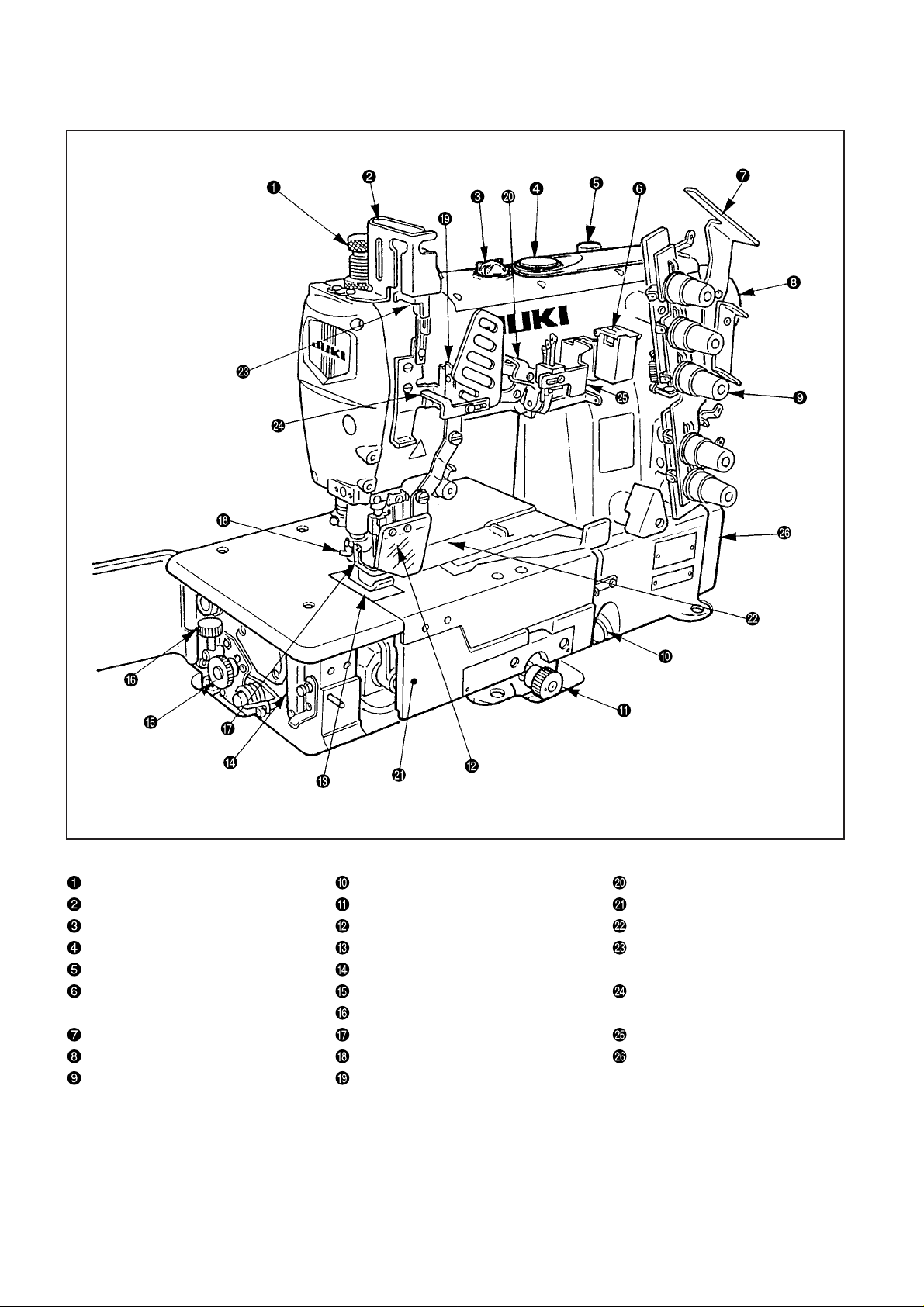
2. CONFIGURATION OF THE MACHINE COMPONENTS
Presser spring regulator Oil gauge Rocking thread take-up
Needle bar thread take-up cover Feed regulating knob Front cover
Oil circulation identification window Eye guard cover Slide cover
Oil hole cap Throat plate Needle bar thread take-up
Micro-lifter Needle tip silicon oil lubricating unit thread receiver
Needle thread silicon Differential lock nut Rocking thread take-up
oil lubricating unit Micro-adjustment knob thread guide
Thread guide No. 1 Finger guard Silicon container thread guide
Upper pulley Thread trimming knife Belt cover
Thread tension nut Rocking thread take-up receiver
– 2 –
Page 7
3. MODEL NUMBERING SYSTEM
(1) MF-7700D Series
Semi-dry head, flat-bed top and bottom coverstitch machine
Applicable model : MF-7700D Series
123456789101112 13 14 15 16 17 18 19 20 21 22 23 24 25 26 27
MF77 D / / –
3 to 6 Model code
7722 2-needle top & bottom covering stitch
7723 3-needle top & bottom covering stitch
7724 4-needle top & bottom covering stitch
11 Tongue shape of throat plate
B Standard
D D-type
15 to 23 Device and attachment
Blank Not provided
TC13 Solenoid type tape cutter
MD10 Mechanical metering device
8 to 10
U10
C10 For collarette For regular binder
E10 Elastic tape attachment With right hook knife
12 to 13 Needle gauge
40 4.0mm
56 5.6mm
60 6.0mm
64 6.4mm
* Selection of 56 and 64 is prohibited for 2-needle type.
* For the triple needle type, the selection of 40 only is possible for the U10.
* Applicable only to 60 for 4-needle type
24 TC control voltage division
A 220 to 440V
B 100 to 240V
C SC-510
Application Description
For universal Lapseam, Covering,
Application code
Hemming
*When device or attachment is one, delete slash
(/) of 14th digit.
26 Specification Code for Destination
A Standard
G For China (domestic China)
H For Turkey
* Selected only for TC unit attachment type
27 Accessory Specification Code
Standard (Foreign language manuals in Japanese, English,
A
Chinese, German, French, Italy, Turkey, and Spanish)
Chinese (available only in China) (2-language manual in
G
English and Chinese)
– 3 –
Page 8

(2) MF-7700D Series Thread trimmer
Semi-dry head, flat-bed top and bottom coverstitch machine
Applicable model : MF-7700D Series Thread trimmer
1 2345678910111213141516171819202122
MF77 D –
3 to 6 Model code
7723 3-needle top & bottom covering stitch
11 Tongue shape of throat plate
B Standard
D D-type
14 to 18 Device and attachment
UT31 Solenoid type vertical thread trimmer unit
UT33 Pneumatic type vertical thread trimmer unit
UT33A Pneumatic type vertical thread trimmer unit (ASTAS)
21 Accessory Specification Code
Standard (Foreign language manuals in Japanese, English,
A
Chinese, German, French, Italy, Turkey, and Spanish)
8 to 10
U10
Application code
Application Description
For universal Lapseam, Covering,
Hemming
12 to 13 Needle gauge
56 5.6mm
64 6.4mm
19 Specification Code for Destination
A Standard
G For China (domestic China)
H For Turkey
22 Control box and motor classification
B SC-500/M50
C SC-510/M51
Chinese (available only in China) (2-language manual in
G
English and Chinese)
– 4 –
Page 9

4. MOTOR PULLEY AND BELT
MF-7700D Series
Sewing speed of the
machine
(sti/min) Pulley size (mm) Belt size (inch) Pulley size (mm) Belt size (inch)
3,500 ø80 M-34 ø65 M-33
4,000 ø90 M-35 ø75 M-34
1 . The table shows the numbers when a 3-phase 2-pole 400 W clutch motor (1/2 HP) is used.
2 . The commercially-available motor pulley near to the counted value is designated since the outside diameter of
the commercially-available motor pulley counts by 5 mm.
3 . When you use a new sewing machine, use the machine at a speed of 4,000 sti/min or less for the first 200 hours
(approximately one month). A good result can be obtained in terms of the durability.
(Caution) 1. Use a motor pulley which is adaptable to this sewing machine.
2. This sewing machine will exceed its max. revolutions and max. sewing speed, finally leading
to the occurrence of malfunction, unless the adaptable motor pulley is used.
50Hz 60Hz
– 5 –
Page 10
5. ST ANDARD ADJUSTMENT
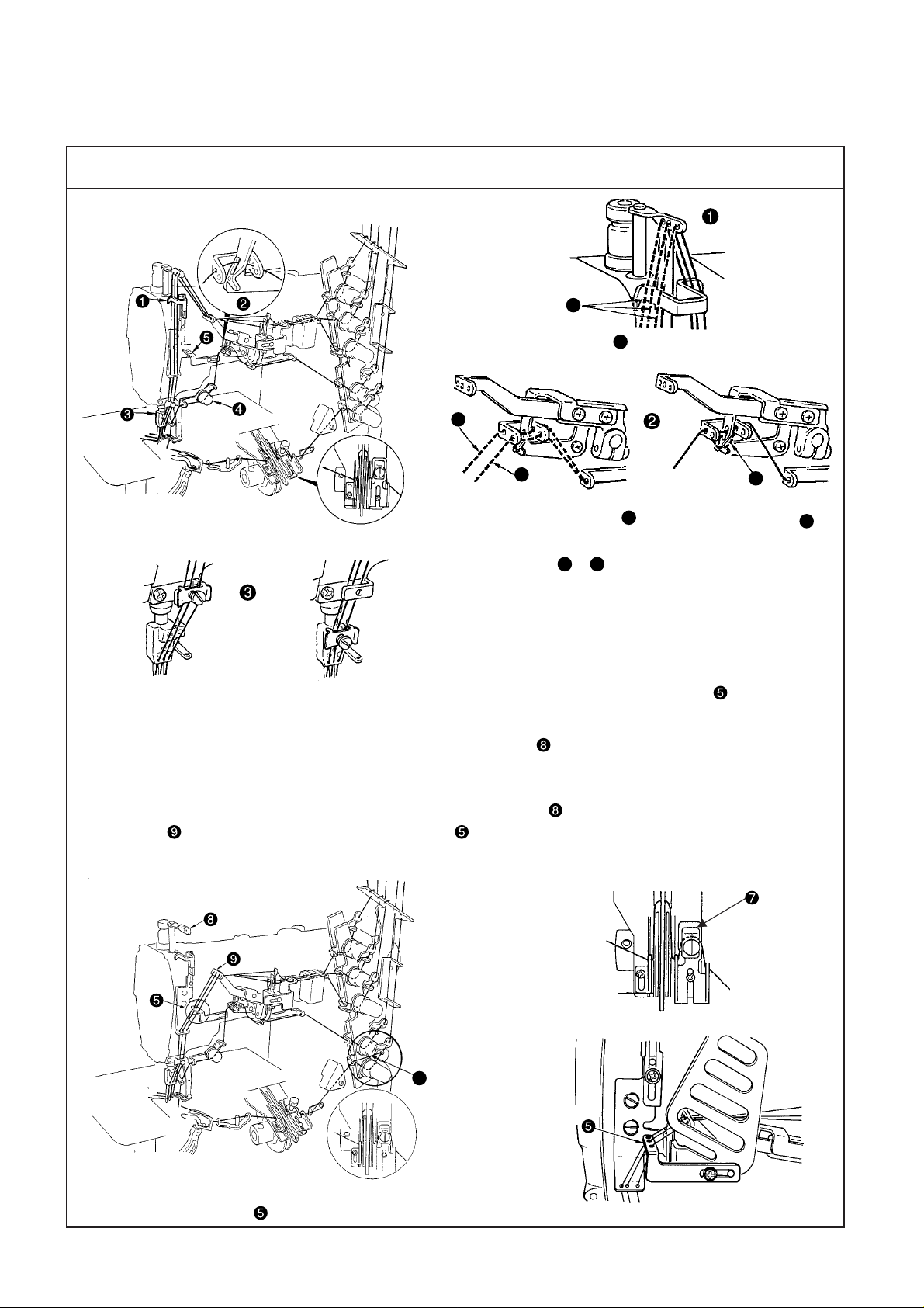
(1) Threading the machine head
Standard Adjustment
1. Threading for standard seam
A
Broken lines A when stretcher thread is used
B
When using more
stretchable thread
When using less
stretchable thread
C
When covering thread is
excessively loosened =
When covering thread is
excessively loosened even
after passing
B
=
B
C
When covering thread is
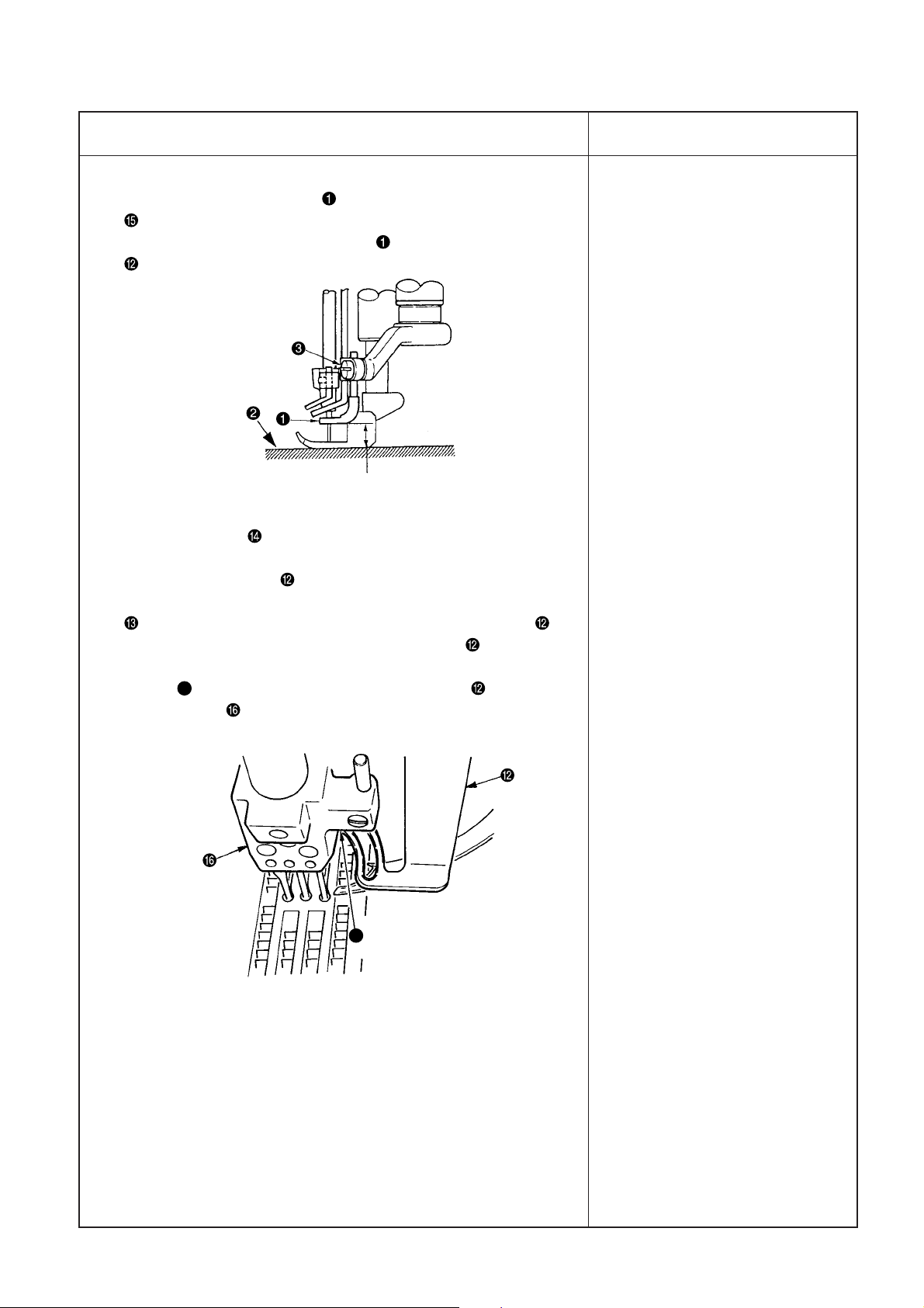
excessively tense =
D
D
(Caution) In case of threading for standard seams, rocking thread take-up thread guide is not used.
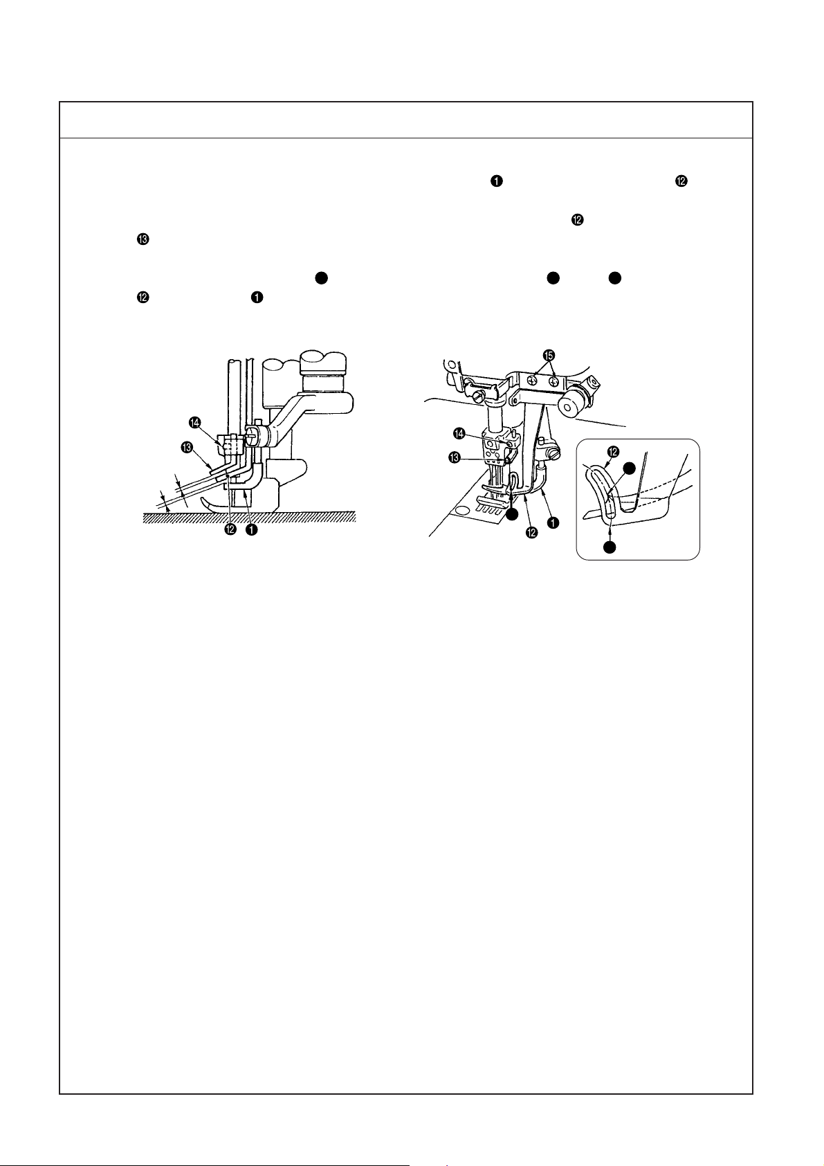
2. Threading for soft seams
(1) Do not pass needle thread through needle bar thread take-up .
(2) When soft seams are required, change the threading of needle thread and slide the position of looper thread
cam eyelet.
(3) Do not pass needle thread through needle bar thread take-up . Pass the thread from rocking thread
take-up to rocking thread take-up thread guide .
(4) Other points are same as those of "1. Threading for standard seam".
In case of soft seams
Engraved marker line
E
(Caution) In case of the soft seams, rocking thread take-up
thread guide is used.
– 6 –
Left
Right
Page 11
Adjustment Procedure
Results of Improper Adjustment
1. When motion of thread is very rough, and stable seams can not be
obtained, there are cases where the condition can be improved by
the following threading.
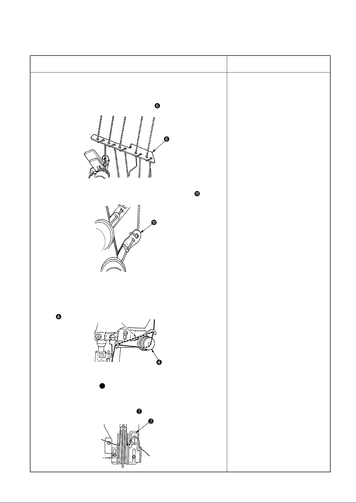
(1) Wind thread around 1st thread guide .
(2) Wind thread around the thread tension thread guide .
o When threading is not properly
performed, not only sewing
trouble occurs, but also needle
breakage is caused. So, be
careful.
2. When using more stretchable thread (wooly thread or the like), the
threading as given below does not make thread stretch and neat
seams can be obtained.
(1) Do not pass thread through spreader auxiliary thread tension
.
Do not pass thread.
(2) Do not pass thread through the looper thread tension disk.
Refer to section E.
(Caution) Even when using wooly thread or the like, seams are
more stabilized by passing thread through looper thread
auxiliary thread tension .
Engraved marker line
– 7 –
Page 12
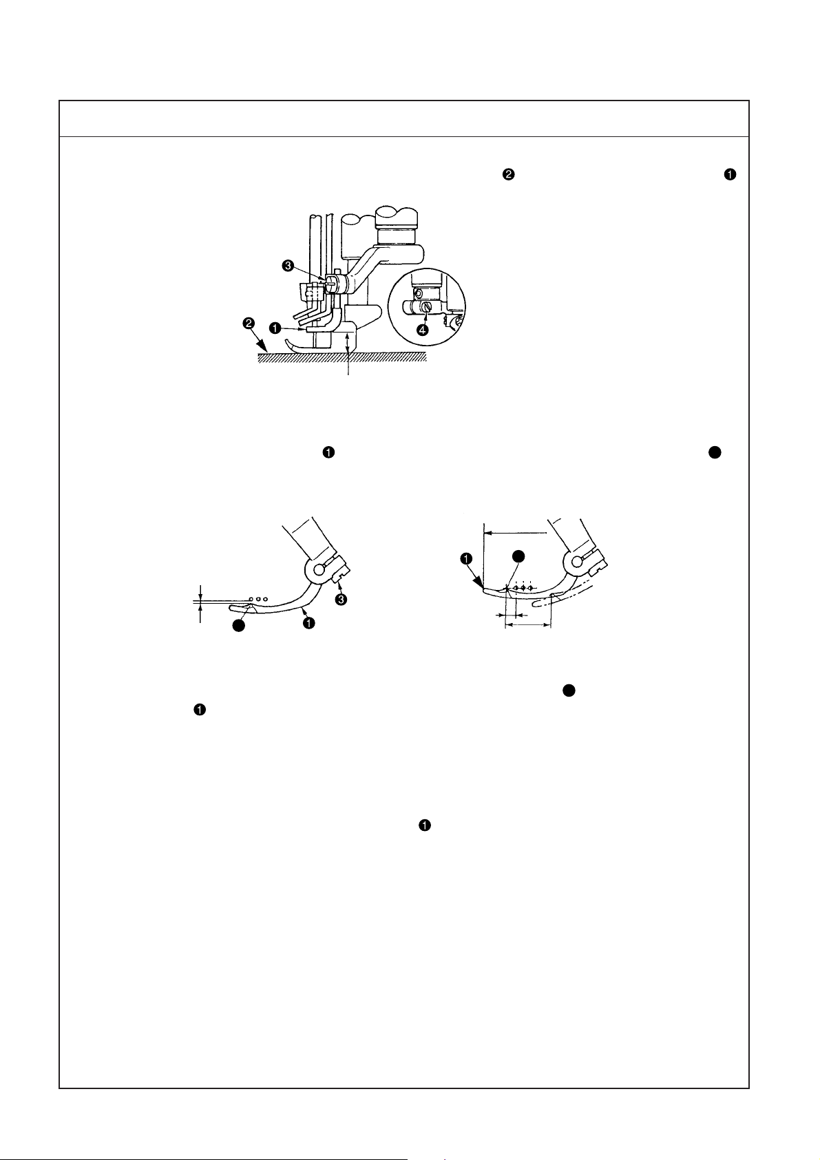
(2) Adjusting the rocking thread take-up
Standard Adjustment
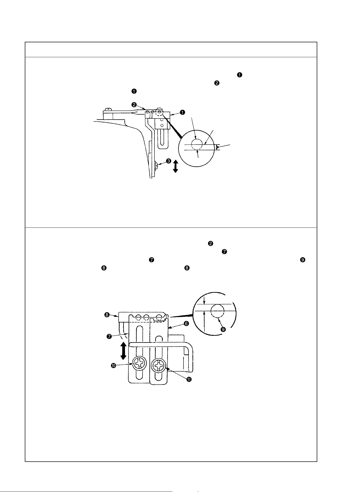
1. Length of the rocking thread take-up
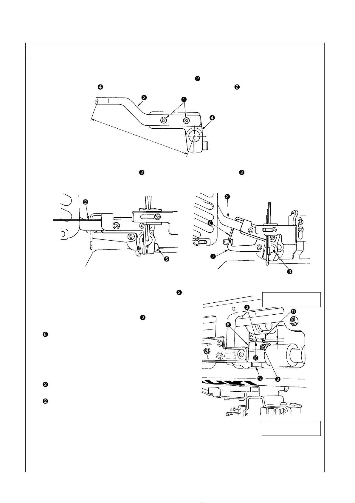
(1) It is the standard that the length of rocking thread take-up from the center of the shaft of rocking thread
take-up support arm to the thread hole face of rocking thread take-up is 95 mm.
95mm
2. Position of the rocking thread take-up
(1) Install so that rocking thread take-up is flush with rocking thread take-up when the needle bar is in its
lowest position.
Flush
3. Timing of the rocking thread take-up
(1) It is the standard timing that rocking thread take-up is in
its lowest position as well when the needle bar is in its lowest
position.
Timing of rocking thread take-up is performed by
adjusting the position of rocking thread take-up ball arm
.
4. Relation between the timing of rocking thread take-up and
the needle thread loop
(1) When using the excessively stretchable thread or the hard-
to-stretch thread, the size of needle thread loop can be
changed by changing the timing of rocking thread take-up
.
(2) Relation between the timing of the rocking thread take-up
and the size of needle thread loop is as shown in the
table on the next page.
(The relation becomes reverse when using the needle bar
thread take-up = standard seams and when it is not used =
soft seams. So, be careful.)
↑
Anti-operatorís side
4mm
Operatorís side
↓
– 8 –
Page 13
Adjustment Procedure
Results of Improper Adjustment
1. Length of the rocking thread take-up
(1) Loosen screws and move rocking thread take-up to the right
or left to adjust the length.
2. Position of the rocking thread take-up
(1) Loosen screw and move rocking thread take-up up or down
to adjust the position.
(Caution) When adjusting the position of rocking thread take-up
, adjust the rocking thread take-up to the same plane
of the edge of rocking thread take-up shaft and fix it
so that spreader thread take-up and spreader thread
guide do not come in contact with each other.
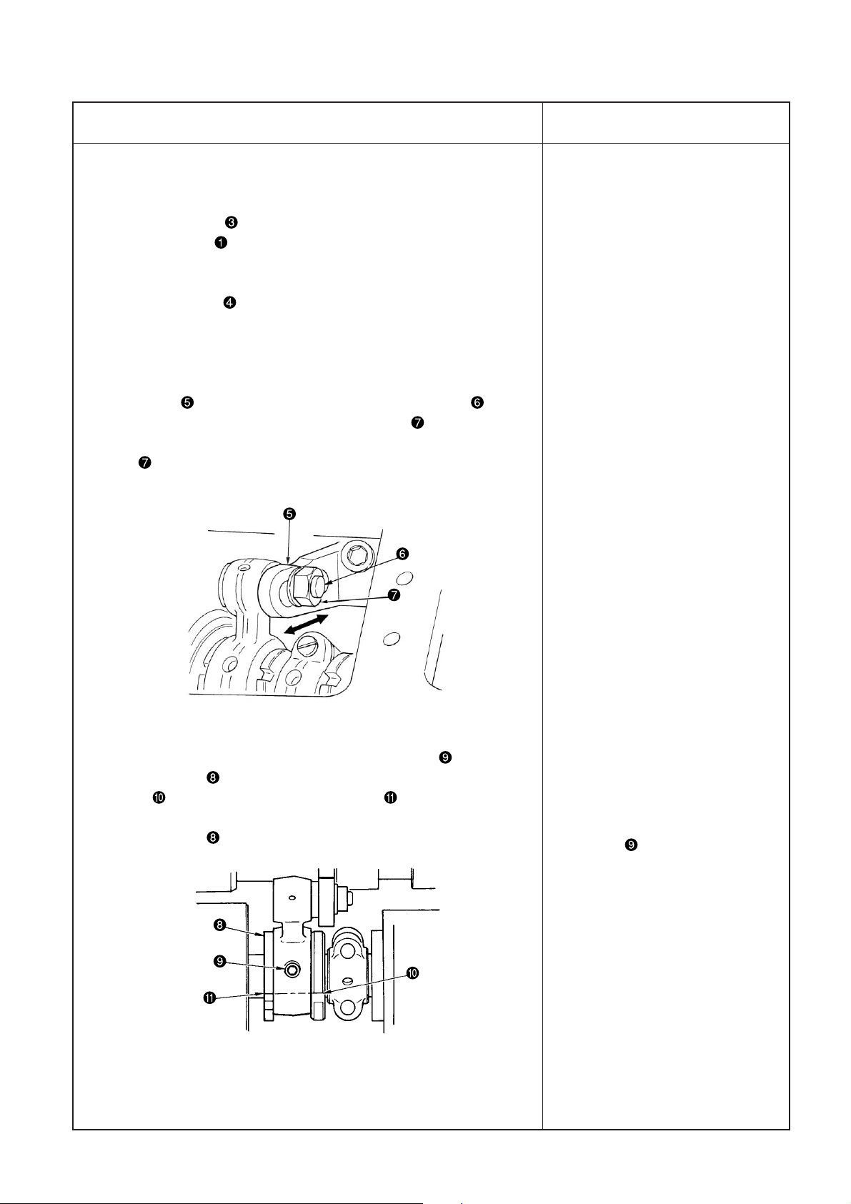
3. To adjust the timing of the rocking thread take-up , remove the
top cover, loosen setscrew in the rocking thread take-up ball arm
and move the position of rocking thread take-up ball arm to and
fro.
(1) Standard adjustment figure is the position where the rear end (anti
operator’s side) of rocking thread take-up ball arm aligns with
engraved marker line on rocking thread take-up shaft . (As the
standard at this time, note that the clearance provided between the
rear end of rocking thread take-up ball arm and thrust collar is
4 mm.)
(Caution) 1. When loosening screw in rocking thread take-up
ball arm , there is a case where rocking thread takeup rotates by its weight. After the adjustment, be
sure to check the rocking position (flush at the lowest
position) of rocking thread take-up .
2. When moving rocking thread take-up ball arm to
the operator’s side, adjust rocking thread take-up ball
arm within the range where it does not come in
contact with rocking thread take-up bushing
(operator’s side).
o When length of rocking thread
take-up is lengthened, needle
thread is tightened.
(Caution) When lengthening
rocking thread take-up
, check whether it
comes in contact with
the thread take-up
cover.
o When length of rocking thread
take-up is shortened, needle
thread is loosened.
o When installing position of
rocking thread take-up is
raised, needle thread is loosened
when the needle bar thread takeup is used, and needle thread is
tightened when the needle bar
thread take-up is not used.
4. Relation between timing of rocking thread take-up and needle thread loop
Delay timing Advance timing
(Move to operator’s side.) (Move to anti-operator’s side.)
When needle bar thread take-up is used Loop becomes small. Loop becomes large.
When needle bar thread take-up is not used Loop becomes large. Loop becomes small.
Adjusting procedure is the same as step 3. Loosen setscrew in rocking thread take-up ball arm and
adjust the position of rocking thread take-up ball arm .
(Caution) Adjust the timing of rocking thread take-up each time in accordance with thread used
or conditions.
– 9 –
Page 14
(3) Adjusting the position of the needle thread guide rod
Standard Adjustment
1. Position of the needle thread guide rod
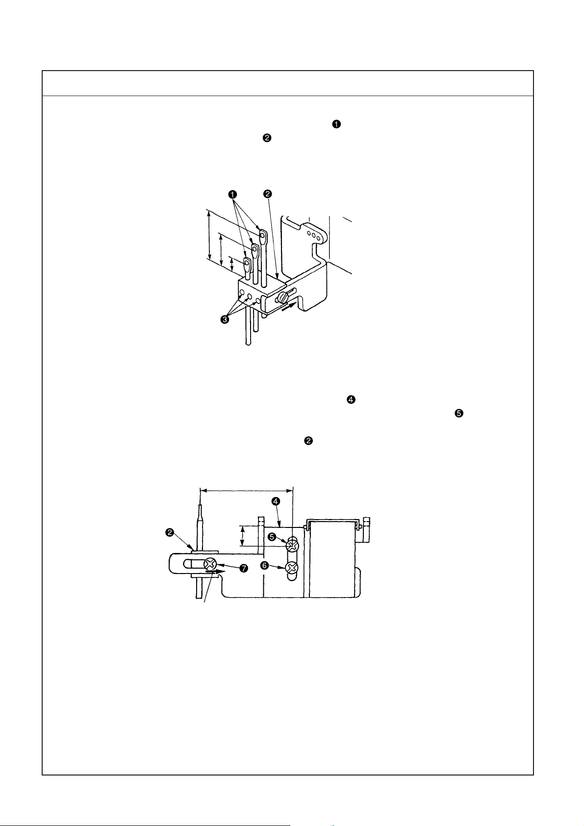
(1) It is the standard that the height of needle thread guide rods is the position where the dimensions from
the top surface of needle thread guide base to the bottom end of the hole are as follows.
Left needle A : 7 mm
Middle needle B : 15 mm
Right needle C : 23 mm
C
B
A
Extreme right position
A : 7mm B : 15mm C : 23mm
2. Adjusting the position of needle thread guide base and silicon container thread guide
(1) It is the standard that the height of silicon container thread guide (refer to 2. CONFIGURATION OF THE
MACHINE COMPONENTS) is the position where the height from the center of setscrew to the bottom
end of thread hole is 9 mm.
(2) Move the lateral position of needle thread guide base fully to the right of slot (43 mm).
43mm
9mm
Extreme right position
– 10 –
Page 15
Adjustment Procedure
Results of Improper Adjustment
1. Loosen setscrews , adjust the height of respective needle thread
guide rods , and fix the rods with setscrews .
(Caution) 1. Move the lateral position of needle thread guide base
fully to the right of slot.
2. When adjusting the height of needle thread guide rods
, install the rods so that the thread holes are parallel
to the thread holes of silicon container thread guide
so that excessive resistance is not applied to
threads.
2. Adjusting the position of needle thread guide base and silicon
container thread guide
(1) Loosen setscrews and and move silicon container thread guide
up or down to adjust the height.
(2) Loosen setscrew and adjust the lateral position of needle thread
guide base .
o When needle thread guide rod
is raised, needle thread is
loosened.
o When needle thread guide rod
is lowered, needle thread is
tightened.
oWhen silicon container thread
guide is raised, needle thread
is loosened.
o When silicon container thread
guide is lowered, needle
thread is tightened.
o When needle thread guide base
is moved to the left, needle
thread is loosened.
– 11 –
Page 16
(4) Adjusting the position of the thread receiver
Standard Adjustment
1. Position of the needle bar thread take-up thread receiver (in case of standard seams)
(1) It is the standard that the height of needle bar thread take-up thread receiver is in the position where the
bottom end of thread hole to the center of needle bar thread take-up aligns with the top surface of needle
bar thread take-up thread receiver when the needle bar is in its lowest position.
Thread hole
Center of hole
This range
To align
2. Position of the rocking thread take-up thread receiver (in case of soft seams)
(In case thread is not passed through needle bar thread take-up )
(1) It is the standard that the height of rocking thread take-up receiver is in the position where the top
surface of rocking thread take-up receiver is in the range of the center to the top end of thread hole of
rocking thread take-up when rocking thread take-up is in its lowest position.
This range
– 12 –
Page 17

Adjustment Procedure
Results of Improper Adjustment
1. Loosen setscrew and move needle bar thread take-up thread
receiver up or down to adjust the height.
2. When desired to make needle bar thread take-up thread receiver
work especially on the right needle where loop is hard to be made,
adjust the height of right needle thread receiver with setscrew .
o When the needle bar thread
take-up thread receiver is
raised, loop becomes large.
o When the needle bar thread
take-up thread receiver is
excessively raised.
1. Loosen setscrew and move rocking thread take-up receiver
up or down to adjust the height.
2. When desired to make rocking thread take-up receiver work
especially on the right needle where loop is hard to be made, adjust
the height of the right needle thread receiver with screw .
– 13 –
Page 18
(5) Adjusting the position of the spreader thread guide and spreader thread take-up
Standard Adjustment
1. Relation of the position between spreader thread take-up and spreader thread guide is the standard
when the top end of thread hole of spreader thread guide aligns with the bottom end of slot of
spreader thread take-up when spreader thread take-up is in its highest position.
Adjust the relation of the position so that thread is moderately stretched when spreader thread take-up
is in its highest position in accordance with thread used or conditions.
Highest position
To align
A
2. Standard position of the spreader auxiliary thread tension
Standard adjustment figure of the spreader auxiliary thread tension is the standard when the top end of
thread tension rod is flush with knob .
– 14 –
Page 19
Adjustment Procedure
Results of Improper Adjustment
1. Loosen setscrews in spreader thread guide and adjust the
position of spreader thread guide . (Spreader thread take-up
is fixed to rocking thread take-up and can not be adjusted in the
height direction.)
2. After the adjustment, turn the sewing machine by hand and check
whether spreader thread take-up comes in contact with spreader
thread guide , or section A of clearance is too small.
3. Adjusting procedure of the clearance
(1) Loosen setscrews in spreader thread guide and adjust in the
lateral direction, or loosen setscrews in the rocking thread takeup and move spreader thread take-up to the right or left to adjust
the clearance.
(Caution) When loosening setscrews in the rocking thread take-
up and adjusting the position of spreader thread takeup , adjust so that 95, length of rocking thread takeup (95mm) does not change.
o When the relation of position
between spreader thread takeup and the spreader thread
guide is not proper, sewing
troubles such as stitch skipping
and the like will be caused.
o If thread is less stretched and
slackness of thread occurs at the
thread take-up section when
spreader thread take-up is in
its highest position, the spreader
fails to pick up thread and stitch
skipping occurs.
o If stretch or feeding of thread is
excessive when spreader thread
take-up is in its highest
position, not only thread on the
seam side is drawn and needle
thread can not be tightened, but
also needle bend or needle
breakage will be caused.
o If stretch or feeding of thread is
excessive when spreader thread
take-up is in its lowest
position, thread slacks when the
spreader moves from left to right
and stitch skipping occurs.
– 15 –
Page 20
(6) Adjusting the spreader
Standard Adjustment
1. Height of the spreader
It is the standard that the height from the top surface of throat plate to the bottom surface of spreader
is 8.3 to 8.7 mm.
8.3 to 8.7mm
2. Longitudinal position of the spreader
It is the standard that when spreader returns from the extreme left position to the right and top end A of
thread hooking section reaches to the front of left needle, the clearance between the spreader and the left
needle is 0.1 to 0.3 mm.
Extreme
left position
A
0.1 to 0.3mm
A
4.5 to 5.5mm
16.0 to 18.0mm
3. Protruding amount
It is the standard that the dimension from the center of left needle to top end A of thread hooking section,
when spreader is in the extreme left position, is 4.5 to 5.5 mm.
4. Spreader stroke
It is the standard that the spreader stroke is 16 to 18 mm at the stroke of thread hooking section.
5. Timing of the spreader
Standard position is the position where the spreader is in the extreme left position when the needle bar
comes down from the upper dead point by 1.1 ± 0.1 mm.
– 16 –
Page 21
Adjustment Procedure
Results of Improper Adjustment
1. Adjusting the height of the spreader
2. Adjusting the longitudinal position of the spreader
Loosen setscrew and adjust the height and longitudinal position
of the spreader .
3. Protruding amount of the spreader
Loosen setscrew in the spreader folder and adjust the protruding
amount. Adjust aiming the adjustment figure of 5 mm.
4. Adjusting the spreader stroke
The standard position is located where the notch section of spreader
drive lever aligns with the shaft center of connecting pin . When
desired to increase the stroke, loosen lock nut and move in the
right direction. When desired to decrease the stroke, loosen lock
nut and move in the left direction. Adjust aiming the adjustment
figure of 17 mm.
5. Adjusting the timing between the needle bar and the spreader.
When changing the timing, loosen two setscrews in spreader
eccentric cam to adjust. Standard position is the position where
notch in the main shaft aligns with notch in spreader eccentric
cam. When changing, turn the upper pulley and change with spreader
eccentric cam fixed.
o Height of the spreader is improper,
stitch skipping of spreader occurs.
o Adjust the height in accordance
with the needle gauge.
o Even when the protruding amount
is excessive or insufficient, stitch
skipping of spreader will be
caused.
o When the protruding amount is
insufficient, it will be the cause for
left needle not to scoop covering
thread at overlapped section.
o When the stroke is increased,
disorder of covering thread
stitching will be caused.
o When the stroke is decreased,
stitch skipping of spreader will be
caused.
o When the timing is excessively
advanced, needle does not take
covering thread when it comes
down and stitch skipping will be
caused.
o When the timing is excessively
retarded, resistance increases
when covering thread slips out
from the spreader and a load is
applied to the right needle. As a
result, needle breakage or stitch
skipping will be caused.
(Caution) When changing,
temporarily tighten No.
2 screw in the rotation
direction of setscrews
and turn the upper
pulley to change.
– 17 –
Page 22
(6) Adjusting the spreader
Standard Adjustment
6. Adjustment figures of the spreader thread guide
(1) It is the standard that the clearance provided between spreader and spreader thread guide is 0.4 to
1.0 mm.
(2) It is the standard that the clearance provided between spreader thread guide and needle clamp thread
guide is 0.8 to 1.2 mm.
(3) Lateral position of the spreader thread guide
Top end of thread hooking section D of the spreader aligns with center E of slot C in spreader thread
guide when spreader is in the extreme right position.
0.8 to 1.2mm
0.4 to 1.0mm
D
C
E
– 18 –
Page 23
Adjustment Procedure
Results of Improper Adjustment
6. Spreader thread guide
(1) Adjust the height of spreader
to 8.3 to 8.7 mm. Loosen setscrews
in the spreader thread guide and adjust the clearance provided
between the top surface of spreader and spreader thread guide
to 0.4 to 1.0 mm.
8.3 to 8.7mm
(2) Needle clamp thread guide
Loosen setscrew in the needle clamp thread guide and adjust
the clearance provided between the needle clamp thread guide and
spreader thread guide to 0.8 to 1.2 mm.
(3) For the lateral direction, align the hole of needle clamp thread guide
to the prolonged line of the slot of spreader thread guide .
(Caution) When adjusting spreader thread guide in the lateral
direction, check whether there is any contact at section
B
(left side of spreader thread guide and needle
clamp )
o When height or position of the
spreader thread guide is improper, stitch skipping of
spreader thread will be caused.
oWhen height or position of the
needle clamp thread guide is
improper, stitch skipping of
spreader thread will be caused.
B
– 19 –
Page 24
(7) Adjusting the timing relation between the looper and needle bar
Standard Adjustment
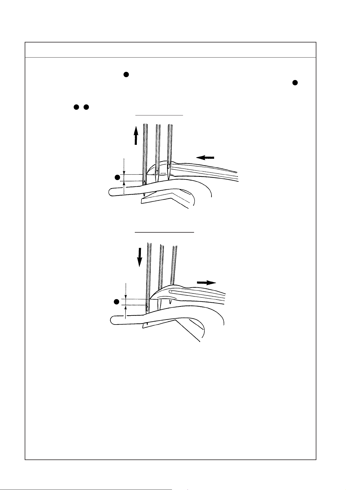
1. Timing relation between the looper and the needle bar (synchronization)
It is the standard that dimension A from the top end of needle eyelet to the blade point of looper passes the
rear of the needle and comes to the position of the right end of left needle is the same as dimension B from
the top end of needle eyelet to the blade point of looper when needle bar comes down from the upper dead
point, the blade point of looper passes the front of needle bar and comes to the position of the right end of
left needle. (A=B)
A
Going of looper
Returning of looper
B
– 20 –
Page 25
Adjustment Procedure
Results of Improper Adjustment
1. To adjust the timing relation between the needle and the looper,
remove the top cover, loosen four setscrews in the sprocket and
turn upper pulley in the state that the sprocket is held.
2. Adjusting procedure
(1) When adjusting the timing to "0" (zero)
1) In case dimension A when the looper advances is smaller than
dimension B when the looper retreats, the looper timing is
retarded (needle timing is advanced). In this case, loosen
setscrews in the sprocket and finely turn upper pulley in
the reverse direction.
2) In case dimension A when the looper advances is larger than
dimension B when the looper retreats, the looper timing is
advanced (needle timing is retarded). In this case, loosen
setscrews in the sprocket and finely turn upper pulley in
the normal direction.
(Caution) Be careful not to excessively turn upper pulley .
oWhen the difference in timing
(going and returning) of looper is
excessively large, stitch skipping
or entangling of needle thread
will be caused.
3. After the adjustment, fix four setscrews in the sprocket.
– 21 –
Page 26
(8) Returning amount of the looper
Standard Adjustment
1. It is the standard that returning amount of looper from top end of looper to the center of needle bar is
6.5 mm regardless of the needle gauge when looper is in the extreme right position.
6.5mm
2. Returning amount of looper for each gauge (dimension A)
2-needle 3-needle
Needle gauge Returning amount
4 4.5 — —
——5.6 3.7
——6.4 3.3
(Dimension
A
is the dimension fromthe center of right needle to the top end of looper .)
A
A
Needle gauge Returning amount
0 to 0.05mm
Unit : mm
A
– 22 –
Page 27
Adjustment Procedure
Results of Improper Adjustment
1. Loosen setscrew in the looper holder and move looper indicator
arm to the right and left for adjust.
2. After the adjustment, tighten setscrew in the looper holder.
Without fine adjustments
With fine adjustments
(Caution) When adjusting looper indicator arm , adjust the lateral
position while being careful that the looper indicator arm
does not move to and fro.
3. Longitudinal position
(1) Without fine adjustments
Adjust so that the clearance provided between blade point of
looper and middle needle is 0 to 0.05 mm when the top end of
looper comes to the center of middle needle from the extreme right
position.
(2) With fine adjustments
Turn adjusting screw to adjust the longitudinal position.
Turn clockwise to move the looper supporting arm to the rear
side and counterclockwise to move it to the front side.
o When the returning amount is
large, loop of needle thread becomes large and it is apt to fall.
As a result, stitch skipping or
thread breakage will be caused,
and stitch skipping on the back
is apt to occur.
In addition, thread tangling will be
caused.
o When the returning amount is
small, loop of needle thread is
small and stitch skipping or
thread breakage will be caused.
In addition, thread tangling will be
caused.
After the adjustment, fix the looper holder with setscrew in the
looper holder.
* Blade point of the looper comes in contact with the right needle
when rear needle guard fails to work. So, be careful.
– 23 –
Page 28
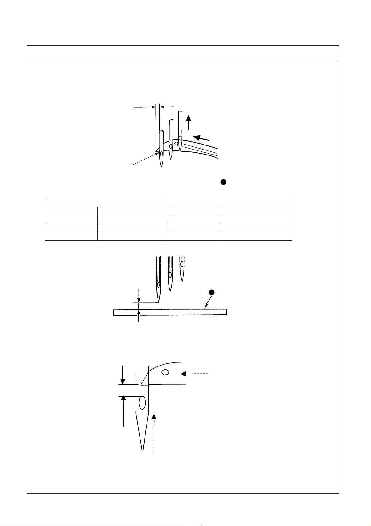
(9) Height of the needle
Standard Adjustment
1. It is the standard that the top end of needle eyelet of left needle aligns with the bottom end of looper when
the top end of looper passes the rear of the needle from the extreme right position and protrudes from the
left end of left needle by approximately 1 mm (1.1 mm), dimension B.
B
To align
Reference : Dimension C, height of left needle from top surface A of throat plate
Unit : mm
2-needle 3-needle
Needle gauge Height of left needle C Needle gauge Height of left needle C
4.0 9.3 — —
——5.6 8.5
——6.4 8.0
A
C
2. Scooping height of looper , dimension from the top end of needle eyelet to the top end of looper is 1.2 to 1.4 mm.
1.2 to 1.4mm
– 24 –
Page 29
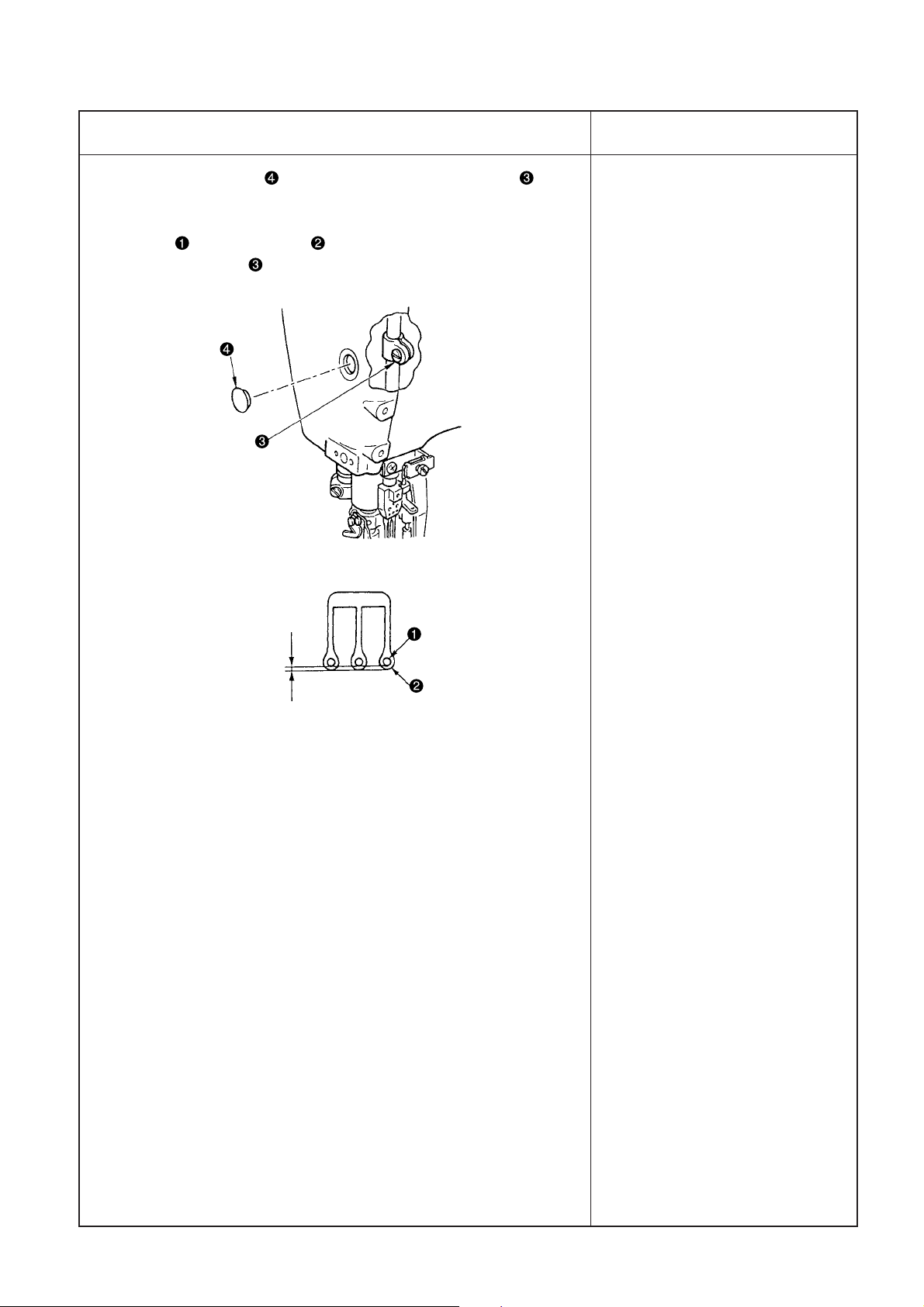
Adjustment Procedure
Results of Improper Adjustment
1. Remove rubber cap in the face plate, loosen setscrew in the
needle bar bracket and adjust the height of the needle bar.
2. After adjusting the height, equally adjust the clearance A between
needle and needle hole in the throat plate and fix the needle
bar with setscrew in the needle bar bracket.
o When the height of the needle
is excessively different, stitch
skipping, needle breakage,
thread breakage, etc. will be
caused.
A
Equal
– 25 –
Page 30
(10)Locus and longitudinal motion of the looper
Standard Adjustment
1. Standard longitudinal motion of the looper
(1) It is the standard that the top end of left needle touches
the position of 1/4 to 1/3 from the bottom face of the
back of the looper when the looper returns from the
extreme left position.
(2) The position where the engraved marker line on looper
drive arm aligns with the center of the shaft of pin
is the standard.
1/4 to 1/3
—
2. Locus of the looper
0.1 to 0.2mm
2.5 to 2.7mm
It is the standard locus of the looper that the
clearance between the top end of looper and middle
needle is within 0.05mm (when the rear needle guard
fails to work) and the looper passes the left needle
with a clearance of 0.1 to 0.2 mm.
+
Lower pulley side
The standard position of the cam is the position
where the notch of looper longitudinal motion
eccentric cam aligns with notches of looper
driving shaft.
– 26 –
Page 31

Adjustment Procedure
Results of Improper Adjustment
1. Changing the longitudinal motion of the looper
(1) Remove 11 setscrews in bed top cover and remove the cover.
(2) When increasing the longitudinal motion of the looper, loosen nut
and lower the arm downward . from the engraved marker line.
(3) When decreasing the longitudinal motion of the looper, loosen nut
raise the arm upward from the engraved marker line.
Perform the adjustment in accordance with the needle used.
(Caution) After adjusting the longitudinal motion of the looper,
move the looper holder and re-adjust the longitudinal
position of the needle and the looper. (Refer to "(8)
Returning amount of the looper.)
2. Changing the locus of the looper
(1) Loosen two setscrews in the cam and change the locus of the
looper by turning the upper pulley with the cam fixed.
When it is turned in the direction of rotation, the timing is retarded,
and when turning in the reverse direction of rotation, the timing is
advanced.
(Caution) 1. It is possible to change the locus of the looper.
However, do not excessively change it from the
standard position.
2. When changing the locus of the looper, be sure to
check whether the top end of left needle touches the
position of 1/4 to 1/3 from the bottom face of the back
of the looper.
—
+
o When the longitudinal motion of
the looper is small, the rate that
needle touches the back of the
looper is increased and blunt
needle tip will be caused.
o When the longitudinal motion of
the looper is large, the clearance
provided between the needle and
the back of the looper is increased
and stitch skipping at the time of
returning of the looper will be
caused.
o When the timing is retarded, stitch
skipping is apt to occur at the time
of going of the looper, and
especially the clearance provided
between the looper and the left
needle is widened.
Needle strongly touches the back
of the looper and blunt needle tip
will be caused.
o When the timing is advanced,
stitch skipping is apt to occur at
the time of returning of the looper.
Chain-off thread does not come
out smoothly.
– 27 –
o When removing the top cover for
adjustment or the like, sealant is
peeled off. As a result, oil leakage
will be caused.
Page 32

(11) Adjusting the needle guard
Standard Adjustment
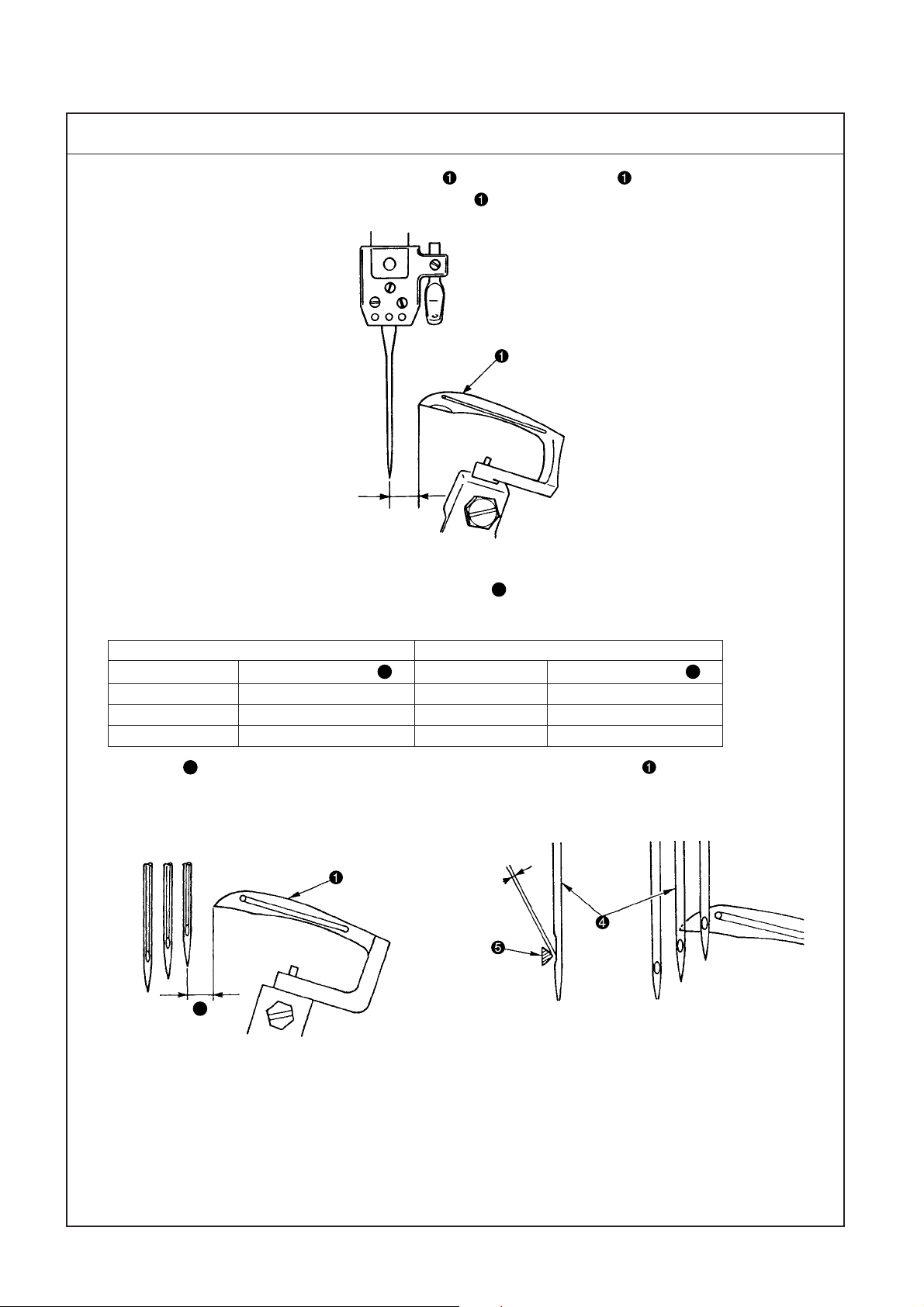
1. Standard position of the rear needle guard
(1) Lateral position of rear needle guard
It is the standard that the lateral position of rear needle guard is the position where the rear needle guard
receives the needle in the range of B.
(2) Position of the height of the rear needle guard
It is the standard that ridge line A of rear needle guard enters in the needle eyelet of right needle when
the needle bar is in its lower dead position.
Details of section A
A
Ridge line
B
Needle eyelet
(3) Pressing amount of the rear needle guard
When the top end of looper comes from the extreme right position to the center of right needle, the
clearance provided between the needle and the top end of looper becomes 0 to 0.05 mm. Make rear
needle guard lightly touch the right needle and the pressing amount of the top end of needle becomes
0.1 to 0.2 mm.
It is the standard for the middle needle that when the top end of looper comes to the center of middle
needle, the clearance provided between the middle needle and the top end of looper becomes 0 to 0.05
mm and the pressing amount of the top end of the needle is such an amount that rear needle guard
lightly touches the middle needle.
0 to
0.05m
m
0 to
0.05m
m
– 28 –
0.1 to 0.2mm
Page 33

Adjustment Procedure
Results of Improper Adjustment
1. Loosen setscrew in the rear needle guard holder and perform
the adjustment in the lateral direction.
2. Loosen setscrew in the rear needle guard and perform adjustment
in the height direction and the direction of rotation.
3. After the adjustment, tighten setscrews and .
(Caution) After the adjustment, check by manual turning whether
the top end of looper does not come in contact with
the needle.
o When the pressing amount of
rear needle guard is small,
needle deflection increases and
stitch skipping, thread breakage,
needle breakage and worn-out of
the top end of looper will be
caused.
– 29 –
Page 34

(11) Adjusting the needle guard
Standard Adjustment
For MF-7700D-U10
(4) Timing of the rear needle guard
The standard position of rear needle guard cam is the position where timing mark in rear needle
guard cam aligns with the center of the notch of looper longitudinal cam .
To align
2. Front needle guard
(1) It is the standard that the clearance provided between front needle guard and the needle is 0.1 to 0.3 mm.
0.1 to 0.3mm
– 30 –
Page 35

Adjustment Procedure
Results of Improper Adjustment
For MF-7700D-U10
4. Remove the bed top cover.
Loosen two setscrews in rear needle guard cam and adjust
the timing.
When moving the cam in direction, timing is advanced, and when
moving in direction, it is retarded.
Pulley side
—
+
—
+
1. Loosen setscrew in the front needle guard and adjust the
clearance.
Adjust so that the clearance provided between the needle and front
needle guard is 0.1 to 0.3 mm when looper moves from the
extreme right position to the left and passes the rear side of the
respective needles and fix the front needle guard with setscrew .
* Place front needle guard as near as the needle to such an extent
that needle thread passes smoothly in accordance with kind and
thickness of thread.
o The cam is excessively changed
from the standard position,
needle breakage or stitch skipping will be caused.
o When the front needle guard and
the needle come excessively
near, stitch skipping or needle
breakage will be caused.
(Caution) Check by manual turning whether the needle is pinched
with front needle guard and the rear needle guard.
– 31 –
Page 36

(12)Installing cover of the looper and needle guard after adjusting
Standard Adjustment
1. Installing bed top cover
A
– 32 –
Page 37

Adjustment Procedure
Results of Improper Adjustment
1. When the adjustment of (10) Locus and longitudinal motion of the
looper or (11) Adjusting the needle guard has been performed, apply
sealant to section A and install bed top cover .
oWhen removing bed top cover
for adjustment or the like, sealant is peeled off and oil leakage
will be caused.
– 33 –
Page 38

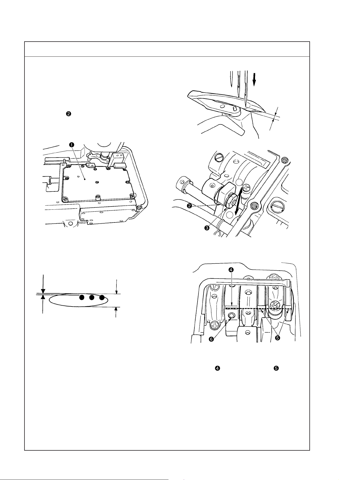
(13)Adjusting the feed dog
Standard Adjustment
1. Height of the feed dog
It is the standard that the height of feed dogs (main feed dog and differential feed dog ) is 1 mm from
the top surface of the throat plate when feed dogs and are in the highest position.
2. Tilt of the feed dog
It is the standard that the tilt of feed dogs and is flush with throat plate when feed dogs and
are in the highest position.
Flush
1mm
– 34 –
Page 39

Adjustment Procedure
Results of Improper Adjustment
1. Loosen setscrew in the differential feed dog and setscrew in
the main feed dog, and adjust the height.
(1) Adjust the top surface of throat plate and the height of the rear
end of main feed dog to 1 mm when feed dogs and come
to the highest position, and fix the main feed dog with setscrew
in the main feed dog.
(2) For the height of differential feed dog , adjust the height of front
end of main feed dog and rear end of differential feed dog
, and fix the differential feed dog with setscrew in the differential
feed dog.
2. Adjusting the tilt of the feed dog
(1) Remove rubber plug in the cover located in the rear of the bed
and loosen the setscrew in the feed tilt adjustment shaft located in
the rear with a hexagonal wrench key of 2.5 mm.
(2) When turning feed dog tilt adjustment shaft to the right or left, the
top ends of feed dogs and move up or down and the tilt of
feed dogs and can be adjusted.
(Caution) After the adjustment check the height of feed dogs
and .
o When the position of the feed
dog is high, stitch skipping, defective chain-off, return of feed,
etc. will be caused.
Throat plate comes in contact
with feed dog and damage of
components or abnormal noise
will be caused.
o When the position of the feed
dog is low, the stitch length
becomes short when the sewing
is finished and performance of
getting over the overlapped
section is deteriorated.
o When the position of the feed
dog is excessively low, looper
and feed dog may come in
contact with each other.
oWhen the tilt of the feed dog is
raised toward you, performance
of catching material is improved.
oWhen the tilt of the feed dog is
lowered toward you, it is effective
in irregular stitches and
puckering.
– 35 –
Page 40

(13)Adjusting the feed dog
Standard Adjustment
3. Lateral position of the feed dog
It is the standard of the lateral position of the feed dog that the left and right clearances A of the feed dog in
terms of the slots of the throat plate are parallel and equal.
A
A
– 36 –
Page 41

Adjustment Procedure
Results of Improper Adjustment
3. Adjusting the lateral position of the feed dog
(1) Remove the bed top cover and remove setscrews in rocking bar
guide 2 .
(Caution) When setting the feed motion amount to 3.6 mm (max.)
and the differential feed ratio to 1 : 1 before the
adjustment, the adjustment at the time of assembling
can be performed with ease.
(2) Loosen setscrew in the feed tilt adjustment shaft and setscrew
in the feed tilt eccentric shaft . Move feed tilt eccentric shaft by
approximately 2mm in the left direction shaft, move feed tilt
Adjustment shaft by approximately 2mm in the right direction,
and open a clearance to the right and left of square block .
(Caution) When moving feed tilt eccentric shaft , lower
downward differential lever pin with differential feed
ratio change lever . Edge of feed tilt eccentric shaft
comes in contact with the pin and a clearance can not
be made.
(3) When loosening setscrew in the differential feed lever and
setscrew in the main feed lever, adjustment of the rocking bar in
the lateral direction can be performed.
(4) Loosen setscrew in rocking bar guide 1 and adjust main feed
rocking bar and differential feed rocking bar to the right and
left so that the clearances of the feed dog in terms of the slots of the
throat plate are parallel and equal with feed dog and throat plate
attached. When the equal clearances are set, tighten setscrew to
fix rocking bar guide 1 , attach rocking bar guide 2 and guide
setscrews , and fix the rocking bar so that it is put between the
setscrews.
(5) Bring feed tilt adjustment shaft and feed tilt eccentric shaft to
their home positions to get rid of the right and left clearances of
square block .
(6) After adjusting the lateral position of the feed dog, loosen setscrew
in the thrust collar , remove the thrust of the shaft with thrust collar
and fix the thrust collar with the setscrew.
(Caution) 1. After fixing, check the lateral play of the rocking bar
by moving the feed dog to the right or left. At the
same time, move the rocking bar to and fro and check
whether it moves smoothly.
2. For the fixing of setscrew in the differential feed
lever and setscrew in the main feed lever, refer to
the longitudinal adjustment value of the feed dog.
3. When fixing setscrew in the feed tilt adjustment
shaft, check the tilt of the feed dog and when fixing
setscrew in the feed tilt eccentric shaft, there
should be no lateral play of square block .
o When the lateral position of the
feed dog is incorrect, worn-out of
throat plate and feed dog will be
caused.
o Heating or abnormal noise will
occur.
o The feed components will wear
out early , or the looseness will be
caused.
– 37 –
Page 42

(13)Adjusting the feed dog
Standard Adjustment
4. Longitudinal position of the feed dog
(1) Position of the main feed dog : it is the standard that the position where the clearance from the edge of the
slot of the throat plate to the front face of the main feed dog is 0.6±0.2 mm at the position where the main
feed dog travels to the extreme front position (operator’s side) when feed momentum is set to 3.6 mm
(maximum).
(2) Position of the differential feed dog : it is the standard that the position where the clearance provided
between main feed dog and differential feed dog is 1.6±0.2 mm when the differential feed ratio is set to 1 :
1 after adjusting the position of the main feed dog.
0.6±0.2mm 1.6±0.2mm
5. For C10
– 38 –
0.6±0.2mm
±0.2mm
1
Page 43

Adjustment Procedure
Results of Improper Adjustment
4. Longitudinal position of the feed dog (condition : feed momentum
3.6 mm (maximum))
(1) When fixing setscrew in the main feed lever , adjust the clearance
from the edge of the slot of the throat plate to the front face of the
main feed dog to 0.6±0.2 mm when the feed dog travels to the
extreme front position (operator’s side), press the main feed lever to
the rocking bar side, and fix it with setscrew.
(2) When fixing setscrew in the differential feed lever, set the
differential feed ratio to 1 : 1, adjust the clearance provided between
the main feed dog and the differential feed dog to 1.6±0.2 mm, press
the differential feed lever to the rocking bar side, and fix it with
setscrew.
(Caution) When the adjustment value changes greatly, feed dog
or throat plate will be broken.
o When the fixing position of the
main feed lever slips greatly out
of position, abnormal noise or
abrasion will be caused.
o When the fixing position of the
differential feed lever slips greatly
out of position, abnormal noise
or abrasion will be caused.
5. For C10
Front and rear positions of the feed dog
(1) When the main feed dog has a pitch of 3.6mm, the clearance
between the most advanced position of feed (worker side) and the
throat plate shall be 0.6 ± 0.2mm.
(2) When the differential feed dog has a pitch of 2.5mm and the
differential feed ratio is 1:1 at that time, the clearance between the
main feed dog and the differential feed dog shall be 1 ± 0.2mm.
– 39 –
Page 44

(14)Adjusting the feed relation
Standard Adjustment
1. Changing the stitch length
It is possible for the standard stitch length to adjust up to 1.2 to 3.6 mm.
Turning feed adjust knob clockwise increases the stitch length and turning it counterclockwise decreases
the stitch length.
2. Changing the differential feed ratio
Differential feed ratio is 1 : 0.7 to 1 : 2 (stitch length : less than 2.5 mm).
Gathering
Stretching
– 40 –
Page 45

Adjustment Procedure
Results of Improper Adjustment
1. When making the stitch length more than 3.6 mm, loosen setscrew
of the feed adjustment stopper pin, turn feed adjust knob
clockwise, and adjust the stitch length. By turning feed adjust knob
, pin is pushed out. Fix pin with setscrew in the feed
adjustment stopper pin after adjusting the stitch length.
Maximum stitch length is 4.4 mm.
o When the stitch length is set to
more than 3.6 mm, the contact
of main feed dog, differential feed
dog and throat plate occurs due
to the adjustment in case of the
standard position of the feed dog.
Additionally machine the feed
dog to satisfy the need.
o When using the machine with the
stitch length of more than 2.5 mm
and the maximum differential
feed ratio, turn the machine by
hand and check whether there is
any contact with feed dog and
throat plate.
In addition, when more gathering
is necessary , grind the differential
feed dog.
2. Loosen differential lock nut and raise lever to increase the
differential feed ratio (shrinkage in stitched material cloth). When
the lever is lowered, the differential feed ratio becomes small
(elongation in stitched material cloth).
Fine adjustment of the differential feed ratio can be performed with
micro-adjust knob .
When engraved marker of the differential feed lever is aligned with
the long engraved marker line on the dial plate, the momentum of the
main feed dog and the differential feed dog becomes almost 1 : 1.
(Caution) For some stitch lengths and differential feed ratios,
improper adjustments may give rise to breakage as a
result of contact between feed dogs or between feed
dog and throat plate.
– 41 –
Page 46

(15)Adjusting the presser foot
Standard Adjustment
1. Height of the presser foot
Height of the presser foot has to be the position the presser foot does not come in contact with other
components at the position where lifter lever is lowered and comes in contact with height adjustment
screw .
Dimension A
8 mm in case of needle gauge 5.6 mm without top covering
5 mm in case of needle gauge 5.6 mm with top covering
2. Position of the thrust collar
(1) Clearance provided between thrust collar and presser shaft bushing is 0.1 mm at the position where
lifter lever is lowered and comes in contact with height adjustment screw .
0.1mm
A
Throat plate
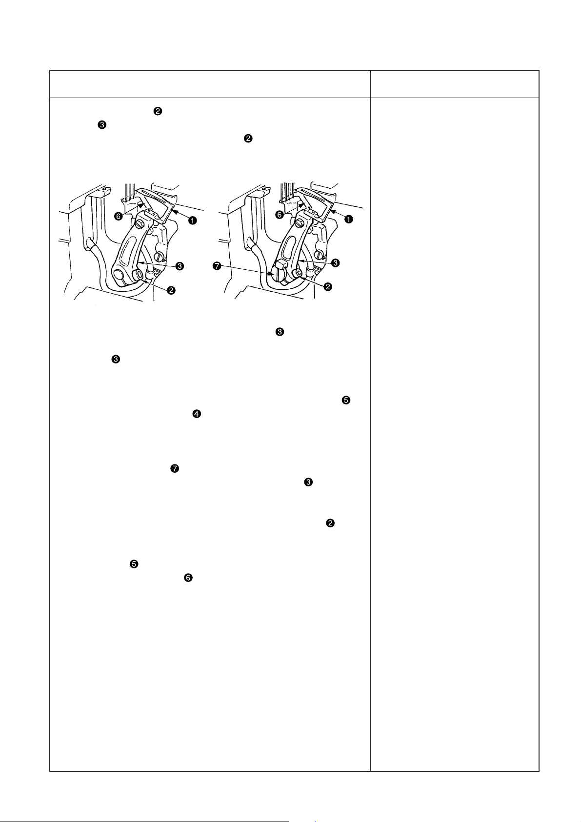
3. Position of the lifter connecting plate
(1) Adjust the clearance provided between lifter connecting plate and hinge screw to 0.5 mm when the
presser foot is lowered in the state that the feed dog comes down below the throat plate.
(2) Adjust so that the needle enters in the center of needle entry of the presser foot and fix the presser foot with
setscrew in the presser bracket.
0.5mm
– 42 –
Center of needle entry
Page 47

Adjustment Procedure
Results of Improper Adjustment
1. Adjusting the height of the presser foot
Loosen adjustment nut . Lower lifter lever , adjust height
adjustment screw , and fix nut at the position where the presser
foot does not come in contact with other components.
2. Adjusting the thrust collar
Loosen setscrew in the thrust collar and adjust the clearance.
When the height of the presser foot is changed, Be sure to perform
the adjustment of the clearance of thrust collar and check the
clearance.
3. Adjusting the lifter connecting plate
For the adjustment of the clearance provided between lifter
connecting plate and hinge screw , loosen setscrew in the
lifter lever shaft when the feed dog lowers from the top surface of
the throat plate and the bottom face of the presser foot comes in
close contact with the throat plate.
o When the position of the presser
foot is too high, it comes in contact with the spreader, and breakage, stitch skipping, etc. will be
caused.
In addition, the needle tip comes
out from the sole of the presser
foot. As a result, sewing material
is damaged or needle breakage
will be caused.
o In case the clearance of thrust
collar is large, when the
presser foot gets over the
overlapped section, the presser
foot comes in contact with other
components and will cause the
damage.
o When replacing the presser foot
due to the replacement of the
gauge or the like, check the
clearance provided between
thrust collar and lifter
connecting plate .
o When the clearance of lifter
connecting plate does not
exist, not only feed force is
reduced but also components
are led to breakage since the
presser foot does not come down
to the top surface of the throat
plate when the feed dog comes
down from the top surface of the
throat plate.
o When adjusting the lever shaft,
adjust the height of lifter lever .
– 43 –
Page 48

(16)Adjusting the micro-lifter
Standard Adjustment
1. Micro-lifter
Adjust the micro-lifter in accordance with sewing conditions for use.
Major applicable process
1. When twist occurs in the hemming bottom process.
2. When tape is twisted in collecting.
Down
Up
– 44 –
Page 49

Adjustment Procedure
1. Adjusting the micro-lifter
(1) When micro-lifter knob is turned counterclockwise, micro-lifter
stopper lower and comes in contact with presser lifting lever .
Then the presser foot goes up.
Adjust the height accordance with the sewing conditions.
(2) When micro-lifter knob is turned clockwise, micro-lifter stopper
is raised and comes in contact with presser lifting lever . Then
the presser foot comes down.
(Caution) When the micro-lifter is not used, turn clockwise micro-
lifter knob and fix micro-lifter stopper at the highest
position.
Results of Improper Adjustment
– 45 –
Page 50

(17)Adjusting the looper thread cam
Standard Adjustment
1. Adjust so that thread comes off from the highest place of looper thread cam when needles come down
and the top end of left needle aligns with the bottom surface of looper . Then tighten setscrews to
fix the looper thread cam.
Theread
To align
2. Preventing thread winding around the looper thread cam
Adjust the clearance provided between the top end of section A of looper thread winding prevention plate
and the edge of looper thread cam to approximately 0 to 0.3 mm (the plate should not come in contact
with looper thread cam ).
A
– 46 –
Page 51

Adjustment Procedure
Results of Improper Adjustment
1. Loosen setscrews in the looper thread cam and adjust while
checking that looper thread comes off from the periphery of the looper
thread cam.
(Caution) When setscrews in the looper thread cam are
loosened, looper thread cam moves in the shaft
direction as well.
Assemble so that the clearances provided between the
cam and the thread guide are equal.
Equal clearances
oWhen the position of looper
thread cam slips greatly out
of position, stitch skipping or defect of thread tightness on the
back of the looper is apt to
occur.
2. Adjusting the looper thread winding prevention plate
Adjust the clearance to approximately 0 to 0.3mm, provided between
the top end of Section A of looper thread winding prevention plate
and the edge of looper thread cam . (Loosen setscrews (2
pcs.) of looper thread cam and move them to the right and left to
adjust the clearance to 0 to 0.3mm. After that, tighten setscrews
(2 pcs.).) Since then, tighten setscrews (2 pcs.) to fix the looper
thread winding prevention plate.
o It is effective to adjust as narrow
as possible the clearance
provided between the top end of
click section (section A) of looper
thread winding prevention plate
and the edge of looper thread cam
. However, when making them
come too near and come in
contact with each other, looper
thread cam is scratched and
winding is caused by this
adjustment, instead.
– 47 –
Page 52

(18)With regard to lubrication
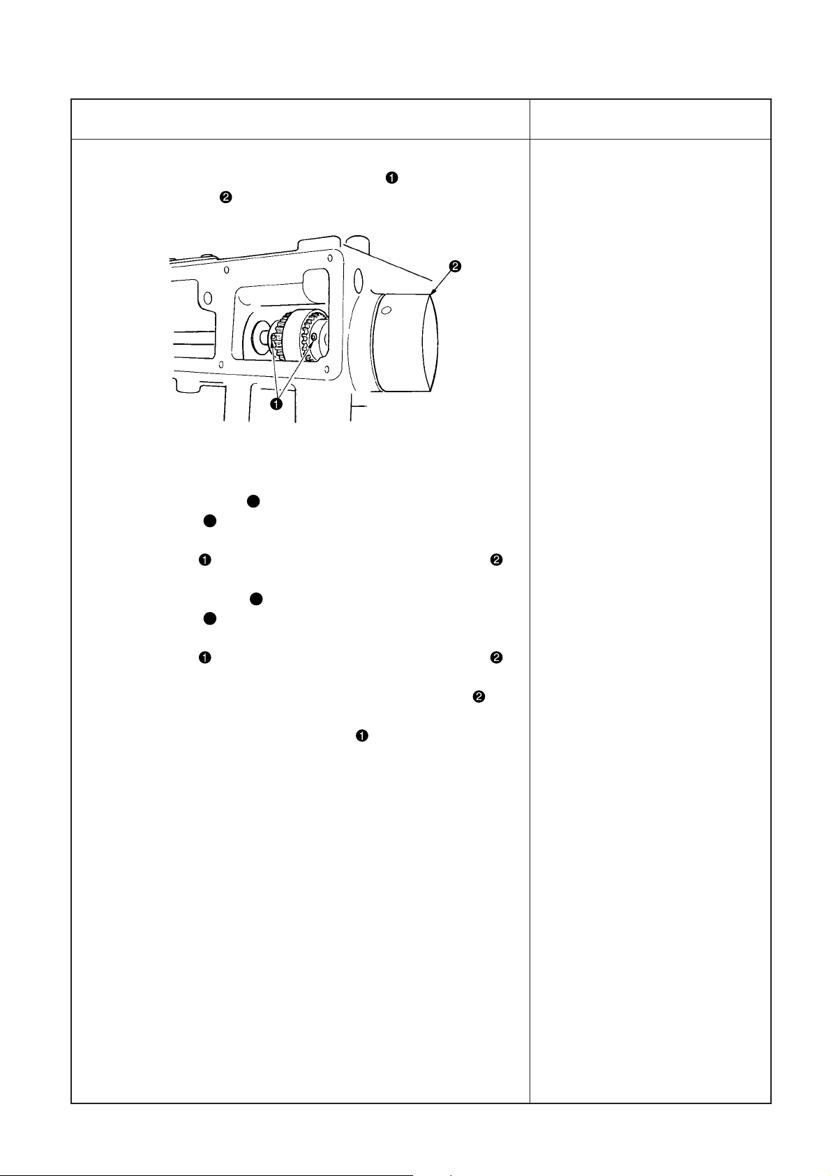
1. Replacing the oil filter
Normal lubrication cannot be performed if dust
collects in oil filter .
Inspect it every 6 months.
Standard Adjustment
2. Oil circulation identification window
Make sure that lubricating oil rises to oil circulation
identification window during operation.
<When using the sewing machine for the first time>
Lubricating oil has been taken out at the time of
delivery. Be sure to supply lubricating oil before
using the sewing machine for the first time.
*Oil used : JUKI MACHINE OIL 18
(Caution) Do not use oil addition agent since
deterioration of lubricating oil or
machine trouble will be caused.
Remove oil hole cap and fill the oil reservoir
with lubricating oil up to the level between the upper
and lower engraved marker lines of oil gauge .
<Checking before using the sewing machine>
1) Check oil gauge and make sure that lubricating
oil level is between the upper and lower two lines.
When lubricating oil level lowers below the lower
line, supply lubricating oil.
2) Make sure that lubricating oil comes out from the
nozzle of oil circulation identification window
when rotating the sewing machine. When
lubricating oil does not come out, perform
"Inspecting and replacing the oil filter ".
Lubrication
– 48 –
Page 53

Adjustment Procedure
Results of Improper Adjustment
1. Inspection and replacement
Loosen setscrews in the oil filter cap and remove oil filter cap .
Draw out oil filter to inspect it. When it is clogged with dust, replace
it with a new one.
After the replacement, fix oil filter cap with setscrews in the oil
filter cap.
(Caution) When removing the oil filter cap , lubricating oil
collected in oil filter will leak out. So, be careful.
2. Oil circulation identification
(1) In case the oil does not come out from oil circulation identification
window even when oil filter is replaced with a new one, remove
six setscrews in the oil pan, remove oil pan , and tilt the machine
head to the rear up to the position where pipe connecting joint screw
can be removed.
(2) Oil sucked up from gear pump passes oil pipe and enters oil
filter from pipe connecting joint screw . When the lubrication oil
does not rise to oil circulation identification window , The hole in
pipe connecting joint screw may be clogged with dust. So, check
it.
(Caution) When there is any foreign material in oil pan , remove
it.
o In case oil cannot be observed
from oil circulation identification
window even when the sewing speed is 2,500 rpm or over,
the machine will be in danger of
seizure if the operation is continued.
– 49 –
Page 54

(18)With regard to lubrication
3. Oiling
Standard Adjustment
No oiling
4. Replacing the lubricating oil
– 50 –
Page 55

Adjustment Procedure
3. Oiling
The mechanisms inside the frame such as the needle bar, presser
lift and spreader components are lubricated with grease. Never add
oil inside the frame.
(Caution) If inside of the frame is oiled, the grease will be expelled,
resulting in mechanical failure.
Results of Improper Adjustment
4. Replacing the lubricating oil
In case of the new sewing machine, replace the lubricating oil (JUKI
MACHINE OIL 18) with new one after using it for approximately one
month. Then replace the lubricating oil every six months.
(1) Set a container to receive the lubricating oil under drain screw
.
(2) Remove drain screw . The lubrication oil is drained.
(3) After the drain, wipe out the oil and attach the drain screw .
– 51 –
Page 56

(19)Setting for functions of SC-500
Functions can be selected and specified by means of the four setting switches and light emitting diode located
inside the front cover of the SC-500.
Specified No. Specified value
Switch for entering specified value changed Down switch (DOWN)
and updating setting No. in DOWN direction Up switch (UP)
Switch for entering specified value changed
and updating setting No. in UP direction
(Caution) 1. Do not perform switch operations other than those described in the following explanations.
2. Be sure to re-turn the power switch ON after one second or more has passed. If the power is
turned ON immediately after turning it OFF, the sewing machine may not work normally.
In this case, turn ON the power again.
How to change over to the function setting mode
(1) Turn OFF the power to the unit.
(2) Pressing switch , turn ON the power to the unit.
(3) Indication , will be shown on the display. (If the
indication fails to change, re-perform the procedure
1) and 2).
– 52 –
Page 57

Specified
No.
(4) When you want to advance the setting No., press
switch to advance the setting No.
When you want to return the setting No., press switch
to return the setting No.
(Caution) 1. When switch (switch ) is held
pressing, the setting No. will return
(will advance) continuously.
2. When the setting No. is advanced (returned), the contents which are before
by one (after by one) will be changing
the contents (up/down switch is
touched).
EXAMPLE) CHANGING THE FLICKER REDUCING
FUNCTION (SETTING No. 5)
Press switch five times to set the setting No. to “5”.
Press switch five times to change the set No. to “5”
since the current set value is displayed on LED .
(Standard : “0”)
(Caution) Keep pressing switch or switch , and
the setting value can be changes continuously.
(5) When the change has been completed, press switch
or to specify the changed value.
(Caution) 1. When turning OFF the power before
performing this work, the contents
which have been changed are not updated.
2. Press switch , and screen display
will change to the contents of thew
setting No. which is before by one.
3. Press switch , and screen display
will change to the contents of next setting No. After completing the operation, turn OFF the power and turn ON
the power again to return to the normal operation.
After completing the operation, turn OFF the power and
turn ON the power again return to the normal operation.
– 53 –
Page 58

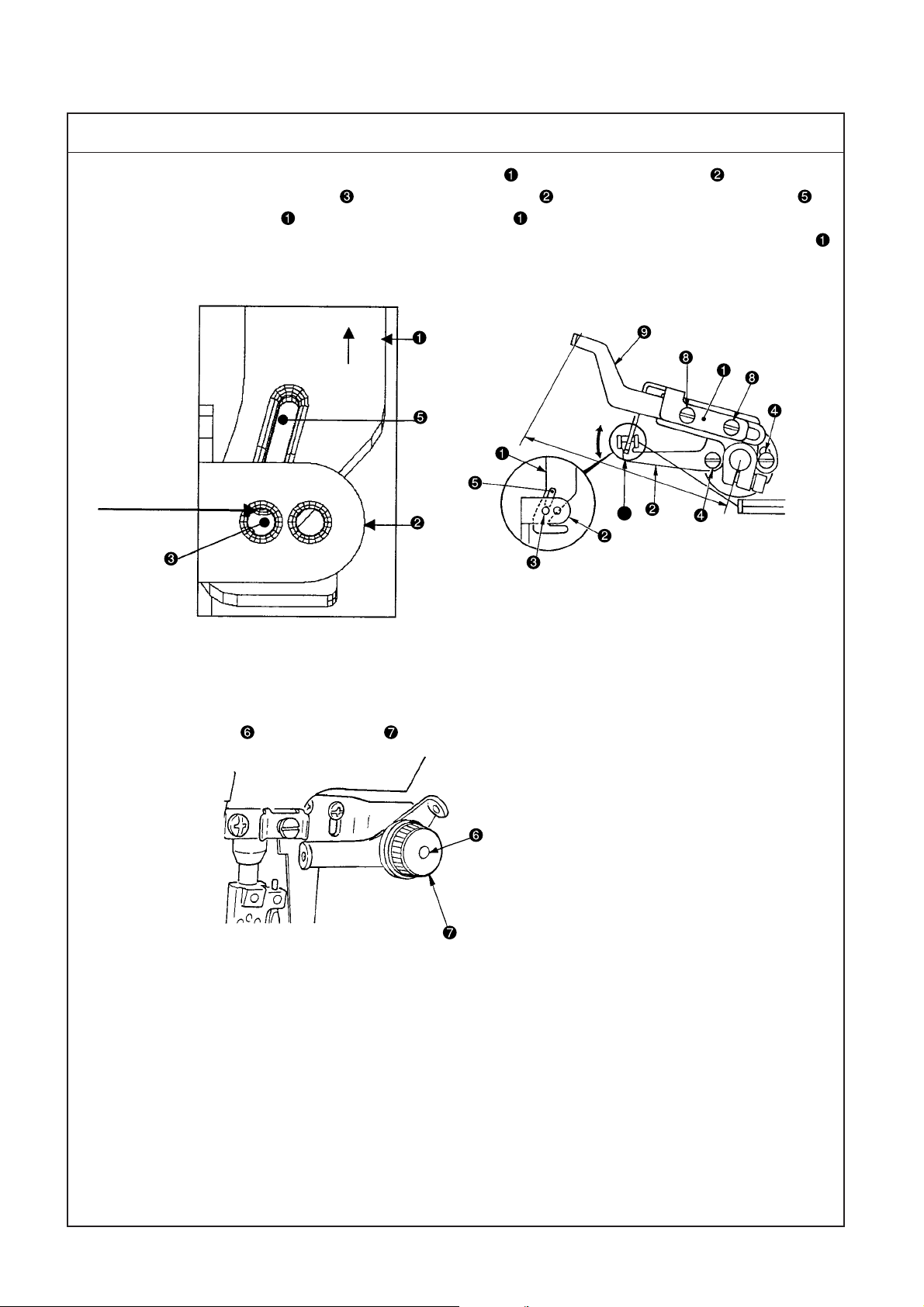
(20) Adjusting and setting SC-510
1. When SC-510 is used, install the motor referring to the Instruction Manual for SC-510.
2. Installation of the synchronizer
1) Synchronizer can be installed by the method below.
2) Using two setscrews , mount synchronizer fixing
plate on the sewing machine. Then, install
synchronizer on it.
3) Fix a cord of synchronizer to synchronizer fixing
plate by means of cable clip band . Fasten the
cord in the illustrated position, using cord clamp
and setscrew .
– 54 –
Page 59

3. Synchronizer adjustments
The synchronizer can be adjusted in the procedures specified below.
WARNING :
To protect against possible injury to hands or fingers due to abrupt start of the machine during performing
adjustment, perform the adjustment of the stop position under the function setting mode.
A
1) Loosen screw and remove cover .
2) Turn disk on this side by hand, and adjust the
adjusting mark “B” of disk in the rear to edge
of disk .
3) Temporarily tighten the synchronizer to the lower
main shaft handwheel with screw .
4) When the power is turned ON, the sewing machine
turns approximately by one half and stops.
5) Turn OFF the power, and loosen screw .
6) Holding section B of the synchronizer so as not to
move, turn the upper main shaft handwheel, and
temporarily tighten screw in the position where
mark of the handwheel is adjusted to mark on
the machine head side.
7) Turn ON the power again and make sure that the
sewing machine stops where mark of the
handwheel is apart from mark on the machine
head side. Then tighten screw .
B
8) After the adjustment, be sure to attach cover and
tighten screw .
9) After the adjustment above has been performed,
when the sewing machine stops at the DOWN position, top end C of the looper is located at the position where it has scooped loop D of left needle
D
thread as shown in the figure.
(Caution) When using the synchronizer as UP/
C
A
DOWN stop position type without using
the thread trimmer device, change the
setting of the function setting No. 74 to
“1 (thread trimming )
→→
→ 0 (UP/DOWN po-
→→
sition)”. (Setting procedure of both SC500 and SC-510 is common.) Thread trimmer safety device error occurs unless the
setting is changed, and it is impossible
to operate the sewing machine. So, be
careful.
– 55 –
Page 60

4. Setting procedure of the machine head
1) Refer to “3-3 Setting for functions of SC-510” in
the INSTRUCTION MANUAL for SC-510, and call
the function setting No. 95.
2) The type of machine head can be selected by pressing switch (switch ).
3) After determining the type of machine head, by
pressing switch (switch ), the step proceeds
to 96 or 94, and the display automatically changes
to the contents of the setting corresponding with
the type of machine head.
(Caution) When the type of machine head is
changed, the contents which have been
changed before return to the standard set
values.
– 56 –
Page 61

5. Machine head list
No. Machine head Type Contents
of display
1MF Semi-dry (MF-7700D/7800D) MF.d 4000 4000
2MF (4 needles) MF.S3 3200 4200
3 MF Roller MF.S1 4000 5000
4 MF Knife MF.S2 4500 5500
5 MF-7823/UT25, MF-77∗∗/UT∗∗ MF 4500 6500
6 16 Class U.16 800 800
7 35800 U.358 4000 4000
8 MS-3580 J.358 4000 4500
9 36200 U.362 3300 3300
10 MO∗∗ MO. 1 4000 5500
11 MO∗∗ MO. 2 7000 8000
12 DU-141H du. 14 2000 2000
13 LU-2210 (VR type) LU. 2v 3500 4000
14 DSU-14∗ dsu 2000 2000
15 DSC-24∗ dsc.0 2200 2200
16 LZH-1290 LZH 2000 2000
17 PLC-1660/1610 PL.66 2000 2000
18 PLC-1710/1760-7 PL.70 2500 2500
19 PLC-1760L PL.7L 1800 1800
20 DNU-1541-7 dnU. 5 3000 3000
21 LS-1342-7 LS.13 2500 2500
22 LU-1510N-7 LU.51 3000 3000
23 LU-1510NA LU.5A 2000 2000
24 LU-1560N-7 LU.56 2500 2500
25 LU-1520N-7 LU.52 3000 3000
26 DLN-6390 DLn 4500 5000
27 MH-48∗ MH.81 5500 5500
28 MH-48∗ MH.82 4500 4500
29 MH-1410 MH.14 4000 5000
30 LU-2216 (VR type) LU.26 3000 3000
31 LU-22∗0 (Special) LU.20 3500 4000
32 LU-2212 LU.12 3500 3500
33 LU-2220 LU.22 3500 3500
34 LT-1040 LT 800 800
35 LH-3500 LH.35 3000 3000
36 DDL-8700 dL.87 4000 5000
37 DDL-8700J dL.8J 4000 4000
38 DDL-5600J dL.6J 4000 4000
39 DDL-5600LUR dL.6L 3000 3000
40 ASN-690 ASn 5500 8000
Sewing speed set at
the
time of delivery speed (sti/min)
from factory (sti/min)
Max. sewing
—
o
+
o Machine head set at the time of delivery
– 57 –
Page 62

(21)MF-7700D/MF-7800D How to use the timing gauge
(Refer to the Engineer’s Manual for the adjustment procedure)
For MF-7700D
4.5
3.7
4.5
(Part No. 40020268)
1.0
5
4.9
3.3
4.1
Unit: mm
4.9
8.5
7.8
For MF-7800D
3.9
3.1
3.9
(Part No. 40020269)
1.0
1. Returning amount of the looper
Move the looper to its back end
(extreme right position), fit the slit
of the gauge to the right needle,
and adjust the returning amount so
Align
that the end of the gauge is aligned
with the blade point of the looper.
– 58 –
7700D and 7800D are different in the returning amount
even when the needle gauge is the same. Use the gauge
on which 7700 is stamped for 7700 or that on which 7800
is stamped for 7800.
MF-7700D
Needle gauge
3.2 4.9
4 4.5
4.8 4.1
5.6 3.7
6.4 3.3
MF-7800D
3.2 4.3
4 3.9
4.8 3.5
5.6 3.1
6.4 2.7
2. Height of the needle bar
Bring the needle bar to the upper
dead point of its stroke, fit the
gauge from the top surface of the
Align
throat plate to the top end of the
left needle, and adjust the height
of the needle bar so that the end
of the gauge is aligned with the tip
of the needle.
7700D and 7800D are different in the height. Use the gauge on which 7700 is stamped for
7700 and that on which 7800 is stamped for 7800. Height of the needle bar varies in accordance with the needle gauges. For the details, refer to the Engineer’s Manual.
MF-7700D Top surface of throat
plate standard
Needle gauge
5.6 8.5
MF-7800D Top surface of throat
plate standard
Needle gauge
5.6 7.8
5
2.7
Unit: mm
Right needle
Returning amount
Right needle
Left needle height
Left needle height
8
4.3
3.5
4.3
standard
standard
3. Spreader
(1) Height of the spreader
Insert the timing gauge between the top surface of the throat plate and the bottom surface of the spreader.
7700D and 7800D are different in the height.
Use the gauge on which 7700 is stamped
for 7700 and that on which 7800 is stamped
for 7800.
Spreader
(3) Clearance between the needle and the
spreader
Insert the gauge between the left needle and
the spreader when the spreader starts to return from the extreme left position to the right
and comes nearest to the left needle, and
adjust the clearance.
mm
(5) Clearance between the fixed thread guide
and the needle clamp thread guide
Bring the needle bar to the lowest position
of its stroke, insert two pieces of the gauge
between the fixed thread guide and the
mm
needle clamp thread guide, and adjust the
height of the needle clamp thread guide.
mm
(2) Protruding amount of the spreader
When the spreader travels to its front end
(extreme left position), fit the left needle to
the slit of the gauge, and adjust the lateral
position so that the top end of the thread
guide of the spreader is aligned with the end
of the gauge.
Aligh
Throat plate
(4) Clearance between the spreader and
the fixed thread guide
Insert the gauge between the spreader and
the fixed thread guide, and adjust the height
of the fixed thread guide.
4. Height of the feed dog
Bring the feed dog to its highest position, put the gauge from the upper part
of the feed dog and adjust the height.
Page 63

6. E10/MD10
(1) Specifications (E10)
Model MF-7700D-E10
Class name Elastic tape attachment with fabric trimmer
Max. sewing speed 4,000sti/min (4,000 sti/min with MD)
Needdle
gauge
Differential feed ratio 1: 0.7 to 1 : 1
Stitch length 0.9 to 3.6mm (Adjustable to 4.5mm)
3-needle 5.6mm, 6.4mm
2-needle 4.0mm
(2) Specifications (MD10)
Model MD10
Class name Mechanical metering device
Max. sewing speed 4,000 sti/min
Needdle
gauge
Tape width 50mm (standard)/80mm *
Amount of tape feeding 0.9 to 3.5mm
*Changeover scheduled
3-needle 5.6mm, 6.4mm
2-needle 4.0mm
– 59 –
Page 64

(3) Adjusting the needle guard
For MF-7700D-E10
1. Most advanced position of the needle guard
E10/MD10
Standard Adjustment
Present status (E10)
195 °
(E10)
180 °
Screw position is used as a mark.
– 60 –
Page 65

E10/MD10
Adjustment Procedure
For MF-7700D-E10
195° Present status (E10)
Position where the root of rod for looper front-rear motion almost
coincides with the center of first screw of the balancer when the rear
needle guard is in the most advanced position.
180° (E10)
Position where the oil hole of rear needle guard rod almost coincides
with the rear end of first screw of the balancer when the rear needle
guard is in the most advanced position.
Results of Improper Adjustment
– 61 –
Page 66

(4) Adjustment of knife
Standard Adjustment
1. Adjustment procedure of the knife pressure
Strong
Weak
E10/MD10
2. Adjustment procedure of knife cutting position
Body part
Left needle
Right needle
Elastic tape
Cutting position
– 62 –
Page 67

E10/MD10
Adjustment Procedure
1. Adjustment procedure of the knife pressure
The fabric trimmer pressure or the pressing force to mesh with the
counter knife should be made as small as possible within the range
where the material cloth can be cut smoothly.
The knife pressure can be made stronger when setscrew of
thrust collar A is loosened and the spring is pressed to the right
and tightened.
Results of Improper Adjustment
o Too weak knife pressure may
cause the knife to be displaced
due to the presence of the step
section or the like, and the cut
section does not become parallel
to the stitches.
oToo strong knife pressure may
cause the fixed knife to be
abraded sooner.
2. Adjustment procedure of knife cutting position
Adjust the distance between the right needle and the cutting position
as described below.
(1) Loosen setscrew and turn adjusting screw to adjust fabric
trimmer and fixed knife to the right and left.
The fabric trimmer and fixed knife move to the left when
adjusting screw is turned clockwise. They move to the right
when the adjusting screw is turned counterclockwise.
(2) Tighten setscrew after adjustments.
(3) After the adjustment, perform the adjustment of the knife
pressure again.
– 63 –
Page 68

Standard Adjustment
3. Adjustment procedure of engagement amount of knives
0.5mm
Lowest knife position
E10/MD10
4. Replacement procedure of fabric trimmer and fixed knife
Processed plane A
– 64 –
Page 69

E10/MD10
Adjustment Procedure
3. Adjustment procedure of engagement amount of knives
(1) Loosen setscrew where fabric trimmer stays in the lowest
position so that fabric trimmer can be moved vertically.
(2) Adjust the amount of fabric trimmer and fixed knife
engagement to about 0.5mm from the tip of the fabric trimmer
and tighten setscrew . At that time, sliding arm should
be positioned somewhat toward the left side so that it does not
come in contact with square block cover .
Results of Improper Adjustment
o If the amount of engagement is
insufficient, the cutting amount
becomes smaller compared with
the feeding amount. As a result,
finished stitches become ugly.
o If the amount of engagement is
excessive, the amount of
abrasion becomes large at the
fixed knife.
4. Replacement procedure of fabric trimmer and fixed knife
To replace fabric trimmer , remove setscrew , guard , and
setscrew . When mounting it again, press it against the processed
plane A and stop it there.
For the replacement of fixed knife , loosen screw and remove
the old fixed knife .
– 65 –
Page 70

(5) Presser adjustments
E10/MD10
Standard Adjustment
– 66 –
Page 71

E10/MD10
Adjustment Procedure
1. Adjustment procedure of front-up amount of the presser foot
When sewing a thick rubber sheet or the like together, fabric can be
smoothly fed by raising the front of presser foot .
Loosen nut , turn setscrews to the right (clockwise), and raise
the front of presser foot for adjustment.
2. Adjustment procedure of the position of the tape guide
Loosen setscrew , and move tape guide base to the right and
left to adjust the position of the tape.
3. Adjustment of tape guide width
According to the tape width, loosen screw and adjust tape guide
to the right and left.
4. Adjustment of fabric presser
According to the knife cutting position, loosen screw for adjustment
so that hook knife can enter knife guide .
Results of Improper Adjustment
– 67 –
Page 72

(6) Method of lubrication
1. Lubrication to bearings
E10/MD10
Standard Adjustment
Left side
2. Lubrication to clutches
Right side
B
A
– 68 –
Page 73

E10/MD10
Adjustment Procedure
1. Lubrication to bearings
• At the time of shipment from the factory, grease is applied to
bearings.
(1) Remove screws and from both end sections of the shaft and
feed the attached grease sufficiently.
(2) After grease replenishment, mount screws and on both end
sections of the shaft.
Results of Improper Adjustment
2. Lubrication to clutches
• At the time of shipment from the factory, grease is applied to
clutches.
(1) Remove the Phillips screw (+) from the clutch A section where
grease is specified.
(2) Replenish the specified grease through the A section.
At that time, keep on feeding the new grease until it comes out of
the B section.
(3) After replenishment, attach the screw (+) to the clutch A section.
(Cautions)1. Greasing to the clutch should be carried out at the
intervals of 100 hours of working based on general
standard practice.
2. At the time of delivery or starting operation after
replenishment, a surplus grease may leak out of the
clutch through of the B section. In such a case, wipe
off the leaking grease.
(Appropriate grease: JUKI Part No. 13525506)
– 69 –
Page 74

(7) Adjustment of the amount of feeding
Standard Adjustment
1. Adjustment of the amount of feeding with a cam
E10/MD10
For tape feeding of 0.6 to 1.5mm
(Shipment from the factory)
For tape feeding of 1.4 to 3.3mm
– 70 –
Page 75

E10/MD10
Adjustment Procedure
By adjusting eccentric cam B , the amount of tape feed, 0.6 to 1.5mm
(at the time of shipment from the factory), can be adjusted within the
range of 1.4 to 3.3mm.
(1) Remove the pulley cover and the pulley.
(2) Loosen two screws at eccentric cam B .
For tape feeding of 0.6 to 1.5mm:
Where the notch of eccentric cam B comes in contact with the right
side of screw , fix eccentric cam B by tightening its screw.
For tape feeding of 1.4 to 3.3mm:
Where the notch of eccentric cam B comes in contact with the left
side of screw , fix eccentric cam B by tightening two screws.
Results of Improper Adjustment
– 71 –
Page 76

(8) Adjustments for heavy material sewing
Standard Adjustment
1. Standard adjustments
E10/MD10
Engraved line B
Engraved marking dot
Standard adjustments (Shipment from the factory)
2. Adjustments for heavy materials (3.5mm or above)
Engraved marking dot
Engraved line A
Adjustments for heavy materials (3.5mm or above)
– 72 –
Page 77

E10/MD10
Adjustment Procedure
1. Standard adjustments
For standard adjustments, the status is that engraved line B meets
the engraved marking dot.
(Shipment from the factory)
Results of Improper Adjustment
2. Adjustments for heavy materials (3.5mm or above)
These adjustments are applicable where heavy materials of 3.5mm
or above are processed by joining fabrics and tapes.
(Standard adjustments have been finished at the time of shipment
from the factory.)
Adjustments are carried out as specified below.
(1) Remove the pulley cover and the pulley.
(2) Loosen two setscrews of eccentric cam A and two
setscrews of eccentric cam B .
(3) Adjust engraved line A of eccentric cam A to the engraved
marking dot that is located on shaft . Then, tighten setscrews
and that have been loosened as per (2) above.
– 73 –
Page 78

(9) Mounting position of the eccentric cam
Standard Adjustment
A
E10/MD10
B
C
– 74 –
Page 79

E10/MD10
Adjustment Procedure
Mounting position of the eccentric cam
(1) Assume the state that eccentric cam B is kept contact with the
A
section of eccentric cam A , as illustrated.
(2) Tighten screws and (2 pcs. each) of eccentric cams A and
B , respectively as illustrated, so that clearances B and C among
washer , pointer , and rod are equally maintained under the
condition that butterfly nut is tightened.
(Caution) Try to turn the pulley by hand after adjustments and
confirm that it can be moved smoothly.
Results of Improper Adjustment
– 75 –
Page 80

MEMO
– 76 –
Page 81

7. MF-7724DU10D60 (4 needles)
(1) Specifications
Model name Semi-dry head, flat-bed top and bottom coverstitch machine
Model MF-7724D
Stitch type ISO standard 607
Example of application Lap seam to knits and jersey products
Max. sewing speed 4,000 sti/min (at the time of intermittent operation)
Needle gauge 4-needle .............6.0 mm
Differential feed ratio
Stitch length 1.2mm to delivery adjustment 2.5 mm (can be adjusted up to 4.4 mm)
Needle SMX1014B #9S to #12S (Standard #10S)
Needle bar stroke 31 mm (Standard)
Dimensions (Height) 451 x (Width) 515 x (Length) 265
Weight 46kg
Lift of presser foot
Feed adjustment method
Looper mechanism Spherical rod drive method
Lubricating system Forced lubrication method by gear pump
Lubricating oil JUKI MACHINE OIL 18 (Equivalent to ISO VG18)
Oil reservoir capacity Oil gauge lower line : 600 cm3 to upper line : 900 cm
Installation Semi-submerged type
1 : 0.7 to 1 : 2 (stitch length : less than 2.5 mm)
Micro-differential feed adjustment mechanism is provided. (Micro-adjustment)
5 mm (with top covering)
Micro-lifter mechanism is provided.
Main feed ................dial type stitch pitch adjustment method
Differential feed .......
lever adjustment method (micro-adjustment mechanism is provided.)
3
(2) Needle
Japan No. 9 10 11 12
German No. 65 70 75 80
The needle used for this sewing machine is SM1014B.
For the needle No., select a proper needle in accordance with the
sewing conditions.
– 77 –
Page 82

(3) Standard adjustments
1) Needle mounting
1. Attaching the needle
MF-7724DU10D60
Standard Adjustment
GOOD
NG
Scart
– 78 –
Page 83

MF-7724DU10D60
Adjustment Procedure
1) Loosen setscrew and needle with a screwdriver.
2) Hold the new needle with its scart made to face the rear and insert
it to the end of the hole of needle clamp .
3) Securely tighten setscrew of the needle .
Results of Improper Adjustment
o If needle is not entered
completely, this can be a cause
of stitch skipping.
– 79 –
Page 84

2) Threading the machine head
MF-7724DU10D60
Standard Adjustment
1
3
2
B
C
When covering thread is excessively
loosened =
When covering thread is excessively
loosened even after passing B =
B
C
1
D
When covering thread is excessively tense =
D
2
E
Broken line E when using more
stretchable thread
3
When using more stretchable thread
– 80 –
Page 85

MF-7724DU10D60
Adjustment Procedure
1. When motion of thread is very rough, and stable seams can not be
obtained, there are cases where the condition can be improved by
the following threading.
(1) Wind thread around 1st thread guide .
(2) Wind thread around the thread tension thread guide .
Results of Improper Adjustment
o When threading is not properly
performed, not only sewing
trouble occurs, but also needle
breakage is caused. So, be
careful.
(Caution) Even when wooly thread or the like is used, stitches
will become more stable when the thread is passed
through bobbin thread minor tension .
Engraved line
– 81 –
Page 86

3) Adjusting the rocking thread take-up
MF-7724DU10D60
Standard Adjustment
1. Length of the rocking thread take-up
(1) It is the standard that the length of rocking thread take-up from the center of the shaft of rocking thread
take-up support arm to the thread hole face of rocking thread take-up is 90 mm.
90mm
2. Position of the rocking thread take-up
– 82 –
Page 87

MF-7724DU10D60
Adjustment Procedure
1. Length of the rocking thread take-up
(1) Loosen setscrews move rocking thread take-up to the right
and left, adjust so that 90 mm is given from the thread hole to the
center of rocking thread take-up shaft , and fix setscrews as
shown in the figure.
2. Position of the rocking thread take-up
(1) Align the center of thread hole of rocking thread take-up with the
upper end plane of cover when the rocking thread take-up is
at its lowest position, and fix the cover with screw .
(Caution) When adjusting the position of rocking thread take-up
, adjust the rocking thread take-up to the same plane
of the edge of rocking thread take-up shaft and fix it
so that spreader thread take-up and spreader thread
guide do not come in contact with each other.
Results of Improper Adjustment
o When length of rocking thread
take-up is lengthened, needle
thread is tightened.
(Caution) When lengthening
rocking thread take-up
, check whether it
comes in contact with
the thread take-up
cover.
o When length of rocking thread
take-up is shortened, needle
thread is loosened.
o When installing position of
rocking thread take-up is
raised, needle thread is loosened
when the needle bar thread takeup is used, and needle thread is
tightened when the needle bar
thread take-up is not used.
– 83 –
Page 88

4) Adjusting the position of the needle thread guide rod
MF-7724DU10D60
Standard Adjustment
1. Position of the needle thread guide rod
(1) It is the standard that the height of needle thread guide rods is the position where the dimensions from
the top surface of needle thread guide base to the bottom end of the hole are as follows.
Needle thread guide rods ABCD
Standard seams 17mm 22mm 28mm 31mm
A
Extreme right position
B
C
D
2. Adjusting the position of needle thread guide base and silicon container thread guide
(1) It is the standard that the height of silicon container thread guide (refer to 2. CONFIGURATION OF THE
MACHINE COMPONENTS) is the position where the height from the center of setscrew to the bottom
end of thread hole is 12 mm.
(2) Move the lateral position of needle thread guide base fully to the right of slot (43 mm).
(43mm)
12mm
Extreme right position
– 84 –
Page 89

MF-7724DU10D60
Adjustment Procedure
1. Position of the needle thread guide rod
(1) Loosen setscrews and adjust so that the heights of the respective
needle thread guide rods are the dimensions as shown in the
illustration. Then tighten screws to fix the thread guide rods.
(Caution) 1. Move the lateral position of needle thread guide base
fully to the right of slot.
2. When adjusting the height of needle thread guide
rods , install the rods so that the thread holes are
parallel to the thread holes of silicon container thread
guide so that excessive resistance is not applied
to threads.
Results of Improper Adjustment
oWhen needle thread guide rod is
raised, needle thread is
loosened.
o When needle thread guide rod is
lowered, needle thread is
tightened.
2. Adjusting the position of needle thread guide base and silicon
container thread guide
(1) Loosen setscrews , adjust so that 12 mm is given from the center
of the upper setscrews to the top surface of thread guide, and
tighten the thread guide with setscrews .
Loosen setscrews and adjust the position from the center of
setscrews to the center of needle thread guide rod to the extreme
right position (43 mm). Then tighten setscrews to fix the thread
guide rod.
o When silicon container thread
guide is raised, needle thread
is loosened.
o When silicon container thread
guide is lowered, needle
thread is tightened.
o When needle thread guide base
is moved to the left, needle
thread is loosened.
– 85 –
Page 90

5) Adjusting the rocking thread take-up thread receiver
Standard Adjustment
1. Position of the needle bar thread take-up thread receiver (in case of standard seams)
5mm
MF-7724DU10D60
Front needle thread
– 86 –
Page 91

MF-7724DU10D60
Adjustment Procedure
(1) Loosen four setscrews in the needle thread receiver plate, and
adjust the height. Adjust the left medium needle only to 5 mm and
securely tighten the setscrews .
Align the height of the other needle thread receiving plates with the
needle thread receiving base and fix.
The size of needle thread loop can be changed by adjusting the
height according to the kinds of needle thread.
Results of Improper Adjustment
o When the needle bar thread take-
up thread receiver is raised,
loop becomes large.
o When the needle bar thread take-
up thread receiver is
excessively raised.
(2) Bring the needle bar to its lowest position, loosen setscrew to
adjust so that the needle thread comes is contact with the thread
receiver of the front needle thread, and fix the thread receiver with
setscrew .
– 87 –
Page 92

6) Adjusting the looper
1. Right and left looper positions
3.5mm
2. Front and rear looper positions
0 to 0.05mm
MF-7724DU10D60
Standard Adjustment
7) Adjusting the height of the needle
Standard Adjustment
1. Equally adjust clearance A between needles and needle holes in the throat plate.
A
2. When the needle is in the highest dead point, the height from
top surface A of the throat plate to the top end of left needle is
8.9 mm.
8.9mm
A
– 88 –
Page 93

MF-7724DU10D60
Adjustment Procedure
1. Right and left looper positions
Clearance between looper and the center of right needle (looper
return amount) is 3.5 mm.
Loosen clamp screw and adjust looper supporting arm to the right
and left.
2. Front and rear looper positions
Adjust so that the clearance between blade point of the looper and
left medium needle is 0 to 0.05 mm when the top end of looper
passes 4 needles from the right extreme point.
Turn adjusting screw to adjust the longitudinal position.
Turn clockwise to move the looper supporting arm to the rear side
and counterclockwise to move it to the front side.
After the adjustment, tighten clamp screw to fix the looper.
* The blade point of the looper comes in contact with the right-
hand needle when rear needle guard does not work. So, be
careful.
Results of Improper Adjustment
o When the returning amount is
large, loop of needle thread becomes large and it is apt to fall.
As a result, stitch skipping or
thread breakage will be caused,
and stitch skipping on the back
is apt to occur.
In addition, thread tangling will be
caused.
o When the returning amount is
small, loop of needle thread is
small and stitch skipping or
thread breakage will be caused.
In addition, thread tangling will be
caused.
Adjustment Procedure
After adjusting the height of needle and the clearance between the needle
and the needle hole of throat plate, tighten needle bar bracket setscrew
and attach rubber cap .
– 89 –
Results of Improper Adjustment
oA large difference in needle bar
height will be a cause of stitch
skipping, needle breakage,
thread breakage, and so on.
Page 94

8) Adjusting the rear needle guard
MF-7724DU10D60
Standard Adjustment
0 to
0.05mm
0 to 0.05mm
B
0.1 to 0.2mm
A (0±0.2mm)
9) Adjusting the looper thread cam
Standard Adjustment
Adjust so that thread comes off from the highest place of looper thread cam when needles come down and
the top end of left needle aligns with the bottom surface of looper . Then tighten screws to fix the looper
thread cam.
Thread
Uniform clearance
– 90 –
Page 95

MF-7724DU10D60
Adjustment Procedure
Adjust the lateral position of rear needle guard so that it receives the
needle within the range of B when the needle is in its lowest position.
(1) When the blade point of looper comes to the right end left needle,
adjust the height with setscrew so that the top end of left needle
aligns 0±0.2 mm with the edge line A.
(2) Make rear needle guard sightly come in contact with the left needle
so that the clearance between left medium needle and top end
of the looper keeps 0 to 0.05 mm when top end of the looper
comes to the center of left medium needle at the time of moving of
top end of the looper to the left from the extreme right position.
Perform the adjustment with setscrews and .
(Caution) After the adjustment, check by manual turning whether
the top end of looper does not come in contact with
the needle.
Results of Improper Adjustment
o When the pressing amount of
rear needle guard is small,
needle deflection increases and
stitch skipping, thread breakage,
needle breakage and worn-out of
the top end of looper will be
caused.
Adjustment Procedure
Loosen setscrews in the looper thread cam and adjust while
checking that looper thread comes off from the periphery of the looper
thread cam.
(Caution) When setscrews in the looper thread cam are
loosened, looper thread cam moves in the shaft
direction as well.
Assemble so that the clearances provided between the
cam and the thread guide are equal.
Results of Improper Adjustment
o When the position of looper
thread cam slips greatly out
of position, stitch skipping or defect of thread tightness on the
back of the looper is apt to
occur.
– 91 –
Page 96

10) Installing position of the spreader
MF-7724DU10D60
Standard Adjustment
1. Height of the spreader
It is the standard that the height from the top surface of throat plate to the bottom surface of spreader
is 7.9 to 8.4 mm.
7.9 to 8.4mm
2. Longitudinal position of the spreader
It is the standard that when spreader returns from the extreme left position to the right and top end A of
thread hooking section reaches to the front of left needle, the clearance between the spreader and the left
needle is 0.1 to 0.3 mm.
0.1 to 0.3mm
A
3. Protruding amount
It is the standard that the dimension from the center of left needle to top end B of thread hooking section,
when spreader is in the extreme left position, is 4.5 to 5.5 mm.
4. Spreader stroke
It is the standard that the spreader stroke is 17 to 19 mm at the stroke of thread hooking section.
B
4.5 to 5.5mm
17 to 19mm
*Except for the adjusting values specified above, refer to the adjusting values for standard adjustments.
– 92 –
Page 97

MF-7724DU10D60
Adjustment Procedure
1. Adjusting the height of the spreader
To adjust the height of spreader , loosen spreader setscrew
for adjustment.
2. Adjusting the longitudinal position of the spreader
Loosen spreader setscrew to adjust the front and rear positions
of spreader .
Results of Improper Adjustment
o Height of the spreader is improper,
stitch skipping of spreader occurs.
o Adjust the height in accordance
with the needle gauge.
3. Protruding amount of the spreader
Loosen setscrew in the spreader folder and adjust the protruding
amount. Adjust aiming the adjustment figure of 5 mm.
4. Adjusting the spreader stroke
The standard position is located where the notch section of spreader
drive lever aligns with the shaft center of connecting pin . When
desired to increase the stroke, loosen lock nut and move in the
right direction. When desired to decrease the stroke, loosen lock
nut and move in the left direction. Adjust aiming the adjustment
figure of 18 mm.
o Even when the protruding amount
is excessive or insufficient, stitch
skipping of spreader will be
caused.
o When the protruding amount is
insufficient, it will be the cause for
left needle not to scoop covering
thread at overlapped section.
o When the stroke is increased,
disorder of covering thread
stitching will be caused.
o When the stroke is decreased,
stitch skipping of spreader will be
caused.
– 93 –
Page 98

8. UT31
(1) Installation of SC-500
1. Installing procedure of the synchronizer
UT31
Standard Adjustment
2. Installing procedure of the resistor pack (asm.)
3. Installing procedure of the exclusive cord for MF
– 94 –
Page 99

UT31
Adjustment Procedure
1. Installing procedure of the synchronizer
(1) Using two setscrews , mount synchronizer fixing plate on the
sewing machine. Then, install synchronizer on it.
(2) Fix a cord of synchronizer to synchronizer fixing plate by
means of cable clip band . Fasten the cord in the illustrated
position, using cord clamp and setscrew .
2. Installing procedure of the resistor pack (asm.)
Install resistor pack (asm.) on cylinder installing base with setscrew .
Results of Improper Adjustment
3. Installing procedure of the exclusive cord for MF
Connect the exclusive cords for MF to the respective designated connectors as follows.
• Synchronizer cord → CN33
• Resistor pack asm. → CN32
• Thread trimmer sensor cord → CN42
• Thread trimmer code → CN36
• Presser lifter cord → CN37
– 95 –
Page 100

(2) Change of the setting
1. Automatic presser lifting
FL ON : Auto-lifter device becomes effective.
FL OFF : Auto-liffter function does not work.
(Standard at the time of delivery)
(Similarly , the presser foot is not automatically lifted when programmed stitching is completed.)
UT31
Standard Adjustment
1. To perform re-turning ON of the power, be sure to perform after the time of one second or more
has passed.
(If ON/OFF operation of the power is performed quickly , setting may be not changed over well.)
2. Auto-lifter is not actuated unless this function is properly selected.
3. When “FL ON” is selected without installing the auto-lifter device, starting is momentarily delayed at the start of sewing. Be sure to select “FL OFF” when the auto-lifter is not installed.
2. Ineffective setting of the automatic reverse feed stitching
– 96 –
 Loading...