

Page 1

MEB-3810N
INSTRUCTION MANUAL
COVERI
Page 2

CONTENTS
1. SPECIFICATIONS .............................................1
2. NAME OF EACH COMPONENT
3. INSTALLATION
3-1. Table ............................................................................. 3
(1) Drawing of the stand ....................................................... 3
(2) Drawing of the table(Table-xed type)
(3) Drawing of the table (Semi-sunken type)
3-2. Installing the control box ........................................... 6
3-3. Installing and connecting the power switch
3-4. Taking out the sewing machine
3-5. Installing the sewing machine
(1) In the case of the table-xed type machine head......... 9
(2) In the case of the semi-sunken type machine head....11
3-6. Raising and returning the sewing machine ............ 16
3-7. Installing the poly oiler
3-8. Installing the operation panel
3-9. Installing the regulator and the manifold
3-10. Connecting the cords
3-11. Handling the cords
3-12. Installing the foot pedal switch (optional)
3-13. Connecting the air supply
(1) Connecting the regulator and the manifold ................ 25
(2) Connecting the air tubes
3-14. Installing the air hose ............................................. 27
3-15.
Cautions for the compressed air supply (source
of supply air) facility
3-16. Installing the thread stand ..................................... 29
3-17. Installing the thread guides
3-18. Installing the eye protection cover and the
nger guard
3-19. Installing the cloth chip bag
3-20. Installing/removing the presser unit
................................................. 3
............................................. 19
............................................. 22
..................................................23
.............................................. 26
................................................. 28
.............................................................31
......................2
.......................... 4
...................... 5
............ 6
................................. 8
................................... 9
.................................. 19
............... 20
............ 24
...................................... 25
................................... 30
..................................32
..................... 33
4. PREPARATION BEFORE OPERATION ......... 34
4-1. Lubrication of the machine and how to lubricate .. 34
(1) Lubricating the arm oil tank ......................................... 34
(2) Lubricating the bed oil tank
(3) Lubricating the looper and spreader components
(4) Lubricating the looper bracket oil tank
(5) Lubricating the needle bar and the gear section
4-2. Attaching the needle ................................................. 37
4-3. Threading the machine head
(1) Threading the upper thread (needle thread) ............... 38
(2) Threading the lower thread (looper thread)
(3) Threading the machine with gimp
4-4. How to set the cloth on the sewing machine ......... 40
......................................... 34
.... 35
....................... 35
....... 36
................................... 38
................ 39
............................... 40
5. STRUCTURE OF THE OPERATION
SWITCH
5-1. Structure of the operation panel .............................41
5-2. Temporary stop switch
5-3. Hand switch
5-4. Foot switch (optional)
..........................................................41
............................................. 43
............................................................... 43
...............................................43
6. HOW TO USE THE OPERATION PANEL ......44
6-1. Basic operation of the sewing machine ................. 44
6-2. Setting the thread tension
6-3. Temporarily stopping the sewing machine
........................................44
............ 45
6-4. Performing re-sewing
6-5. Performing threading
6-6. How to use the counter
6-7. When dropping of the knife is temporarily not
desired
6-8. Changing the operation mode
6-9. Changing procedure of the sewing pattern
6-10. Conrming the pattern shape
.....................................................................48
............................................... 46
...............................................47
............................................ 47
................................. 48
............ 50
................................ 50
7. SETTING PROCEDURE OF THE SEWING
DATA
...............................................................51
7-1. Setting the knife No. ................................................. 52
7-2. Setting the cut length
7-3. Setting the cut-before/cut-after knives
7-4. Setting the number of stitches of the parallel
section
7-5. Setting the number of stitches of the eyelet
7-6. Setting the cut space
7-7. Setting the eyelet space
7-8. Knife position compensation
7-9. Number of stitches of sewing end compensation
7-10. Turning angle compensation
7-11. Turning angle compensation at the parallel sec-
tion
7-12. Compensation of eyelet in lateral direction
7-13. Compensation of eyelet in longitudinal direction
7-14. Compensation of eyelet, left in longitudinal
direction
7-15. Compensation of left parallel section of a but-
tonhole
7-16. Compensation of cutting space, left
7-17.
Setting the needle throwing width of the
right bottom of eyelet
7-18.
Setting the needle throwing width of the left
bottom of eyelet
7-19. Setting the needle throwing width ........................58
7-20. Setting the type of bartack
7-21. Setting the length of taper bar
7-22. Setting the number of stitches of taper bar
7-23. Setting the offset of taper bar
7-24. Setting the number of stitches of slant section
of taper bar
7-25. Compensation of the number of stitches of the
right side taper bar
7-26. Setting the straight bar length
7-27. Setting the number of stitches of straight bar
7-28. Setting the overlapping amount of straight bar
7-29. Setting the needle throwing width of straight bar
7-30. Setting the number of stitches of round bar
7-31. Setting the number of overlapping stitches of
round bar 2
7-32. Setting the needle throwing width of the round
bar
7-33. Setting the needle throwing width at the upper
section of eyelet bar
7-34. Setting the reduced sewing speed for straight/
round bar
7-35. Setting the sewing speed
7-36. Setting the reduction speed of eyelet
......................................................................53
............................................................................55
................................................................... 56
.....................................................................57
..............................................................60
..............................................................62
.............................................................................62
.................................................................63
............................................... 52
................... 53
.......... 53
................................................ 54
........................................... 54
...................................54
. 55
................................. 55
......... 56
56
..................... 57
.........................................57
.................................................58
..................................... 58
............................... 59
......... 59
................................ 59
..................................................60
............................... 60
..... 61
... 61
61
........ 62
...............................................63
....................................... 63
................... 63
i
Page 3

7-37. Setting the soft start ............................................... 64
7-38.
Setting the number of stitches at the beginning of
sewing of thread tension
7-39.
Setting the number of stitches at the end of sewing of thread tension
.................................................. 64
................................................. 64
8. ADJUSTMENT OF EACH PART ....................65
8-1. Adjusting the pressure of the cloth trimming
knife
.......................................................................... 65
8-2. Adjusting the stitch bite width
8-3. Adjusting the presser
8-4. Adjusting the presser opening amount
8-5. Adjusting the needle thread drawing amount
8-6. Adjusting the thread take-up thread guide
8-7. Adjusting the remaining amount of the gimp.........70
8-8. Adjusting the gimp thread tension
8-9. Needle thread clamp unit (optional)
8-10. Adjusting the brightness of the hand lamp
............................................... 67
.................................66
.................. 68
........ 69
............. 69
.......................... 70
........................ 71
.......... 72
9. HOW TO USE THE VARIOUS FUNCTIONS ..73
9-1.
Operating procedure of thread tension compensa-
tion of each section
9-2. Changing the setting position of cloth ................... 76
9-3. Changing over the mode of the start switch
9-4. Changing over the presser movement
9-5. Changing over the counter (DOWN counting)
9-6. Changing over to the mode of the stop before
cloth cut
9-7. Copying the pattern data
9-8. Deleting the pattern data
...................................................................76
................................................... 73
.......... 76
................... 76
....... 76
..........................................77
.......................................... 78
(6) Standard of replacing time of the gas spring
(7) Replacing the gas spring
............................................. 95
............. 94
11. EXCHANGING GAUGE PARTS AND OPTIONAL
11-1. Throat plate ..............................................................96
11-2. Presser set
11-3. Presser holding plate
11-4. Cloth cutting knife
11-5. Hammer
11-6. Others
........................................................... 96
............................................................... 96
..............................................97
...................................................97
.................................................................... 98
.......................................................................98
12. TROUBLES AND CORRECTIVE MEASURES IN SEWING
13. MEMORY SWITCH
13-1. Operating procedure ............................................101
13-2. Memory switch list
........................................ 99
.....................................101
................................................ 102
14. ERROR LIST ............................................... 104
15. STANDARD PATTERN LIST
16. SEWING DATA ENTRY SHEET
......................107
..................108
10. MAINTENANCE ............................................ 79
10-1. Looper thread trimming (overall thread trimmer
type)
..........................................................................79
10-2. Timing between the needle and the looper
10-3. Height of the needle bar
(1) Adjusting the needle bar height ................................... 82
(2) Reference height of the needle bar
10-4. Adjustment to prevent triangular stitch skip-
ping in the case of a narrow needle throwing
width
......................................................................... 83
10-5. Clearance between the needle and the looper
10-6. Adjusting the needle guard
10-7. Clearance between the spreader and looper
and the opening timing of the spreader
10-8. Height of the throat plate
(1) Height of the throat plate .............................................. 87
(2) Adjusting the height of the throat plate
10-9. Position of the presser foot ................................... 88
10-10. Adjusting the knife dropping position
10-11. Installing position of the needle thread trim-
ming knife
10-12. Cleaning
10-13. Draining
10-14. Replacing consuamables
(1) Worn-out of the hammer face ...................................... 91
(2) Replacing the cloth cutting knife and the hammer
(3) Replacing the looper thread trimming knife (overall
thread trimmer type)
(4) Replacing the needle thread trimming knife
(5) Changing the thread trimmer retaining plate (needle
thread trimmer type)
................................................................89
................................................................. 90
.................................................................90
......................................... 82
............................. 82
....................................84
.......................................87
..................................... 91
..................................................... 93
..................................................... 94
.......... 79
..... 84
................ 85
...................... 87
................ 88
.... 92
.............. 94
ii
Page 4
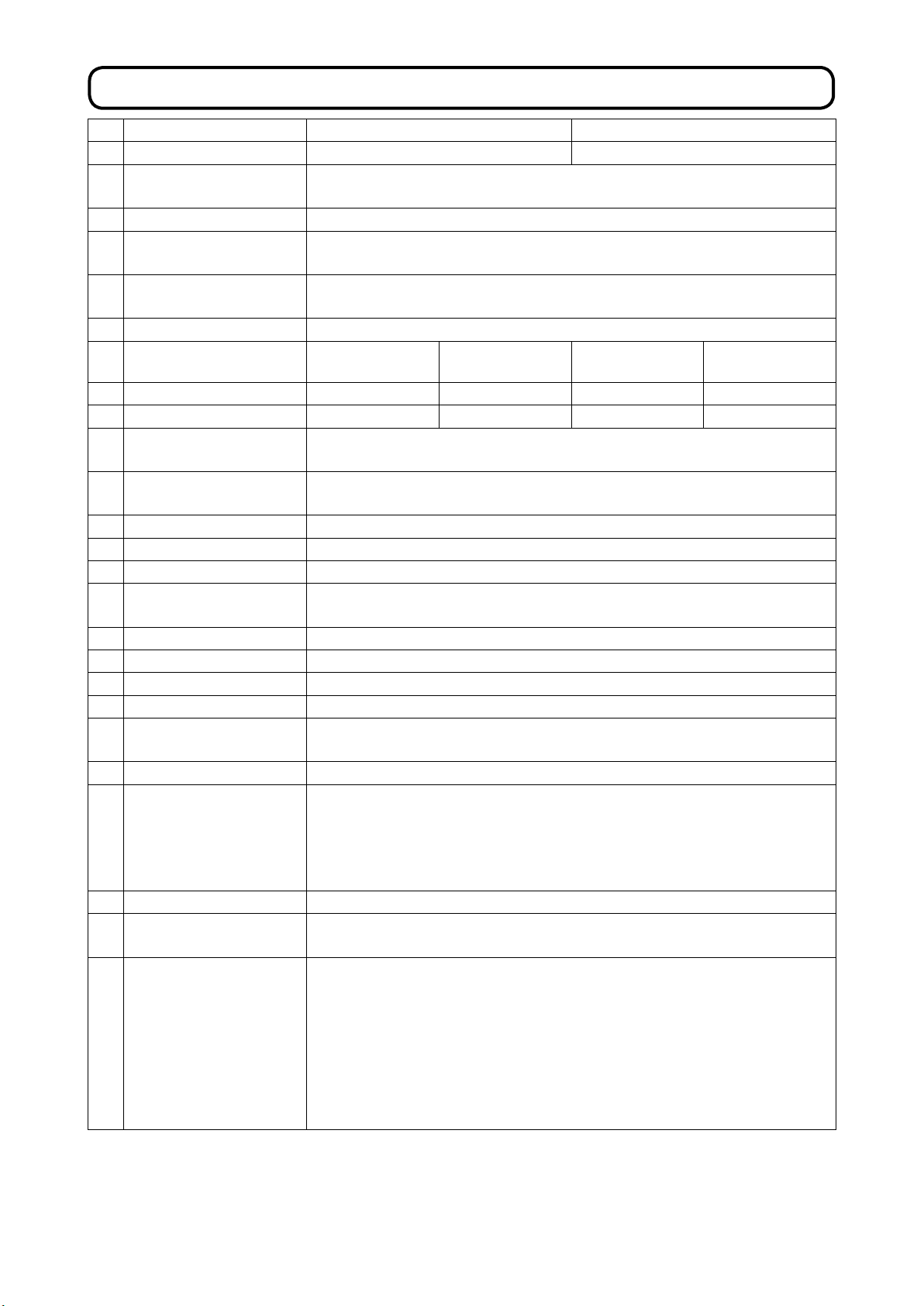
1. SPECIFICATIONS
Specications J type C type
1 Application Jeans Cotton pants, working pants
Operating temperature
2
3 Operating humidity range 35 % to 85 % (with no condensation)
Number of patterns that
4
can be stored in memory
5 Input power
6
7 Thread trimmer type
8 Sewing length 10 to 38 mm 10 to 34 mm 10 to 38 mm 10 to 34 mm
9 Buttonhole length 10 to 38 mm
10 Needle throwing width
Length of buttonhole with
11
12 Lift of presser foot Standard 13 mm
13 Change of stitch shape Selection by program
14 Buttonhole cutting Cut-before knife + Cut-after knife, without knife
Cloth cutting knife drive
15
16 Feed method Intermittent feed by stepping motor
17 Needle used DO x 558 Nm90 to 120 (Needle count attached at the time of delivery: Nm110)
18 Safety device Pause switch & automatic stop function at the time of detection of a trouble
19 Lubricating oil JUKI MACHINE Oil No. 18
20 Air pressure
21 Air consumption
22 Machine dimensions
23 Power consumption 200 VA
24 Mass
25
*1 : For the machine provided with the optional needle thread clamp unit, the buttonhole length is 10 to 28 mm.
*2 : Parallel section: Taper length can be set to such a value that does not exceed the total of the eyelet section and the
bartacking section.
*3 : The height of the completed unit differs with the height of the table stand.
range
Sewing speed
taper bar
method
Noise
99 (1 to 99) (standard patterns have been factory-numbered 90 to 99)
Single-/3-phase 200 to 240 V 50/60 Hz
Supply voltage uctuation: Rating ± 10 %
400 to 2,500 sti/min (in 100 sti/min steps)
Needle thread
trimmer type (00)
*1
2.0 to 4.0 mm (factory-setting at the time of delivery: 2.5 mm)
Hammer pressure regulator: Standard 0.35 MPa (max. 0.4 MPa)
Machine head: 382 mm (width) x 656 mm (length) x 584 mm (height)
: 1050 mm (width) x 700 mm (length) x 1248 mm (height) *3 (excluding the thread stand)
: 1060 mm (width) x 790 mm (length) x 1096 mm (height) *3 (excluding the thread stand)
Machine head: Approx. 110 kg; Operation panel: Approx. 0.3 kg
-
Equivalent continuous emission sound pressure level (LpA) at the workstation :
A-weighted value of 82.0 dB; (Includes KpA = 2.5 dB); according to ISO 10821-
C.6.3 -ISO 11204 GR2 at 2,500 sti/min for the sewing cycle, 3.8 sec. (Pattern :
No.90).
-
Sound power level (LWA) ;
A-weighted value of 92.5 dB; (Includes KWA = 2.5 dB); according to ISO 10821-
C.6.3 -ISO 3744 GR2 at 2,500 sti/min for the sewing cycle, 3.8 sec. (Pattern :
No.90).
Overall thread
trimmer type (01)
10 to 28 mm 10 to 38 mm
[1.5 to 5.0 mm by compensation on the feed panel]
49.5 ℓ /min (11.6 cycles/min)
Complete unit (Table-xed type)
Complete unit (Semi-sunken type)
Control box: Approx. 4.5 kg
5°C to 35°C
Needle thread
trimmer type (00)
3 to 15 mm *2
Driven by air cylinder
Main regulator: 0.5 MPa
trimmer type (01)
*1
Overall thread
10 to 28 mm
– 1 –
Page 5
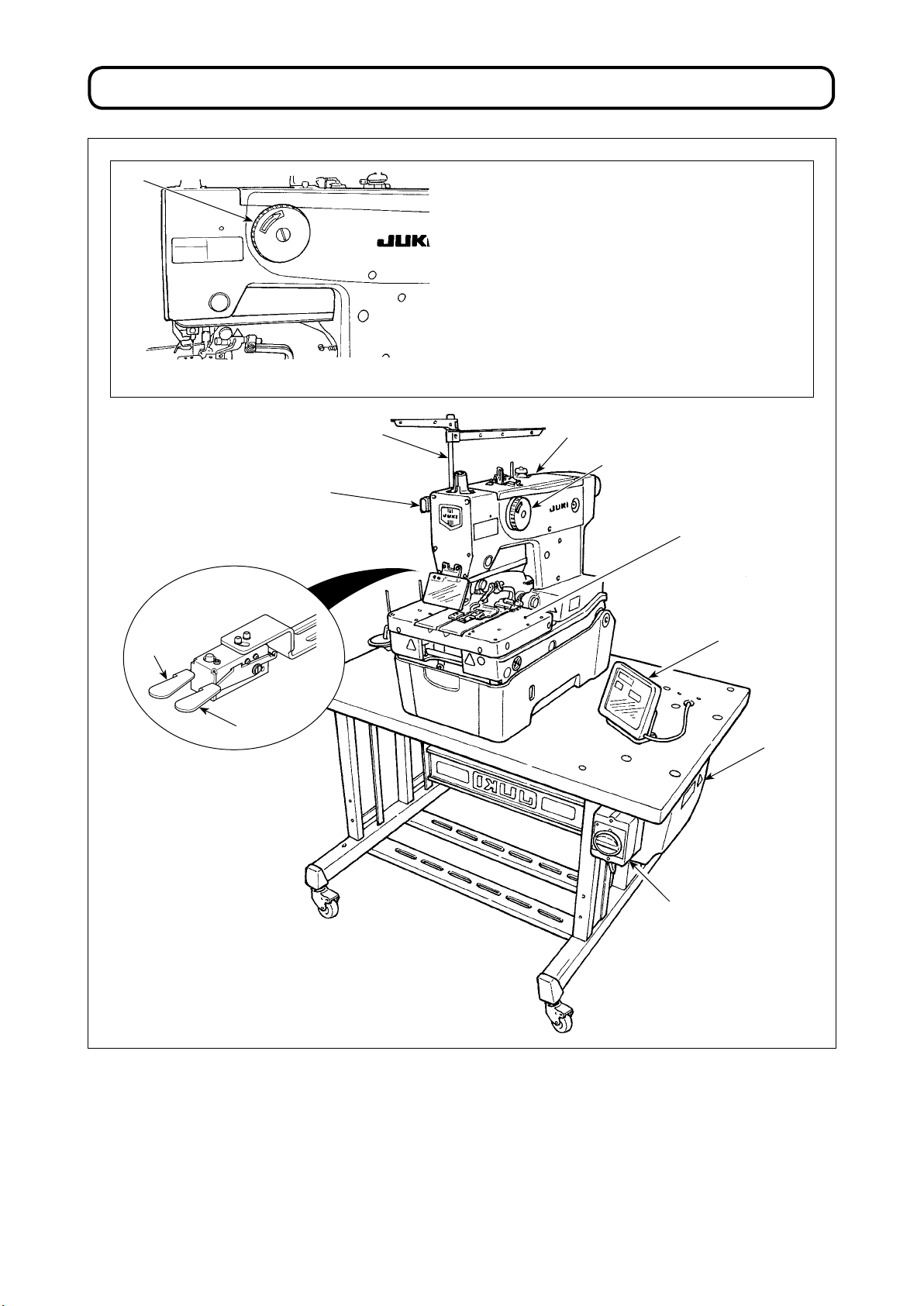
2. NAME OF EACH COMPONENT
❼
❶
❾
• Hand pulley ❼
The needle bar can be lifted or lowered by hand
with the hand pulley.
❽
❼
❸
❷
❶ Temporary stop switch
❷ Presser switch
❸ Start switch
❹ Operation panel
❺ Control box
❻ Power switch
❼ Hand pulley
❽ Machine head
❹
❺
❻
❾ Thread stand
Feed base
– 2 –
Page 6
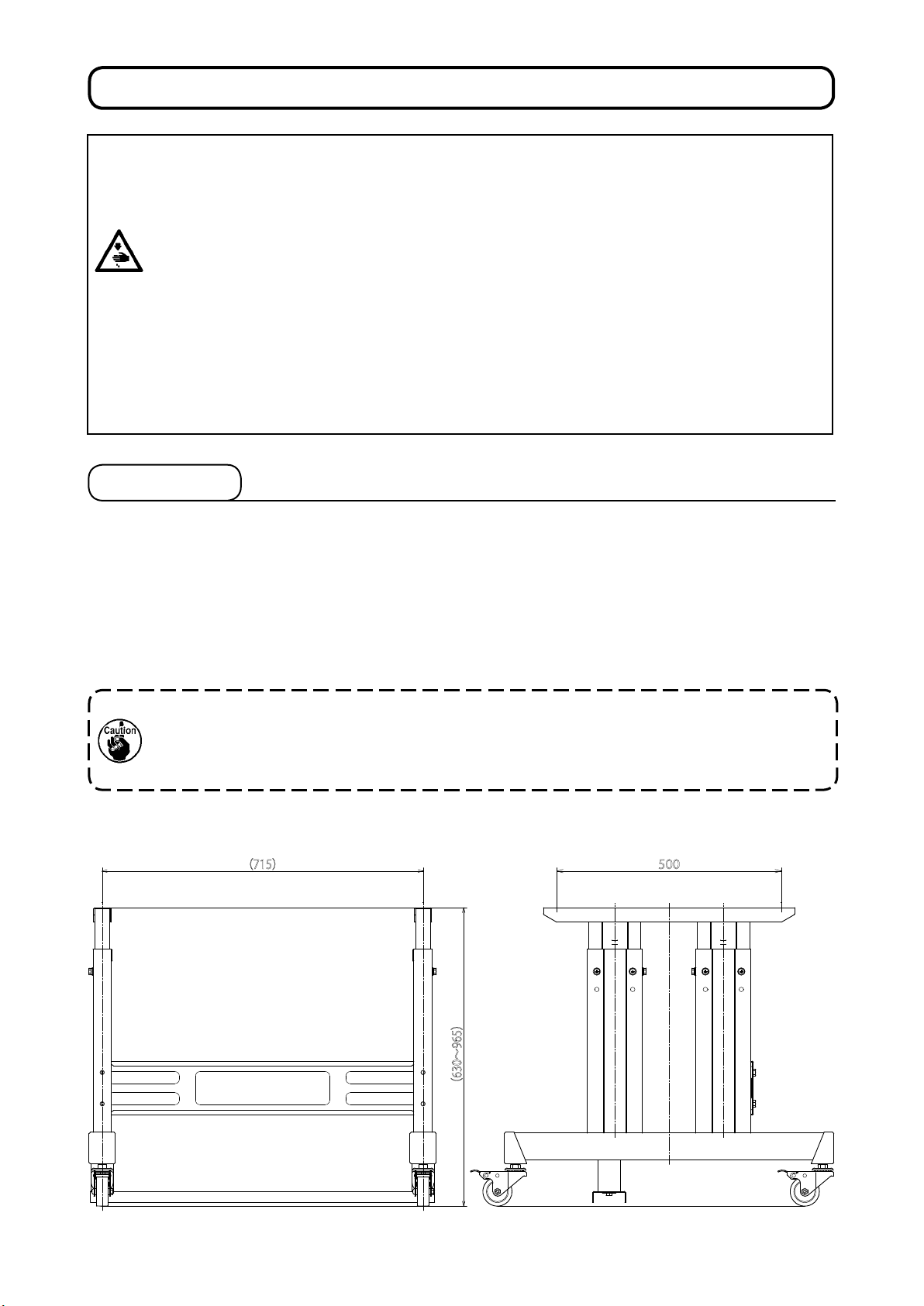
3. INSTALLATION
DANGER :
1. The sewing machine should be installed by a trained technician.
2. Contact the distributor or a professional electrician to ask him/her to carry out electric wiring.
3. The sewing machine has a mass of approximately 110 kg. Four or more workers are required
to carry out the installation of the sewing machine and adjustment of the table height.
4. Never connect the power plug until the installation of the sewing machine is completed in order
to protect against an accident due to an abrupt startup of the sewing machine.
6. Be sure to raise/return the sewing machine from/to its home position by holding it with both
7. Do not apply an unreasonable force to the sewing machine when it is in the raised position. If
• Use the table and stand which are able to withstand the sewing machine mass (110 kg) and vibration. The
• Use the table stand which has an appropriate height for the sake of the operator's ease of use.
• The xing bolt for xing the table and the stand should be of the length which matches the thickness of the
• The table differs between the table-xed type and the semi-sunken type machine heads. Appropriately
5.
Be sure to ground the earthing wire in order to protect against an accident due to electrical
leakage.
hands.
such a force is applied, the sewing machine can lose its balance to fall alone or fall together
with the table, resulting in personal injury or sewing-machine breakage.
3-1. Table
table thickness of which is 40 - 60 mm should be used.
table.
machine the table referring to the table drawing corresponding to the type of the machine head.
1. In the case the table thickness exceeds 60 mm, the length of the bolts supplied with the unit as
accessories is adequate.
2. In the case the xing bolt for xing the table and the stand is too long for the table thickness,
unexpected injury to hands or head can occur.
(1) Drawing of the stand
(715)
(630~965)
500
– 3 –
Page 7
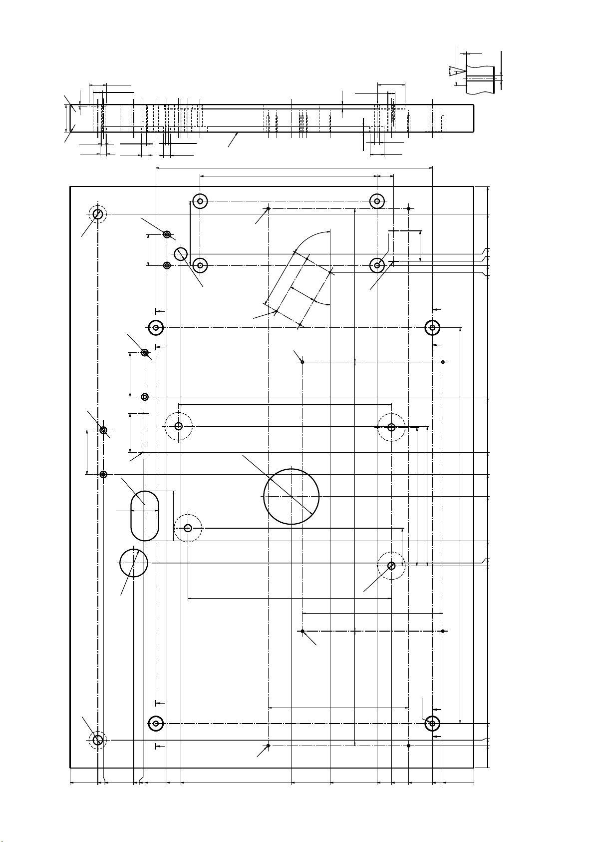
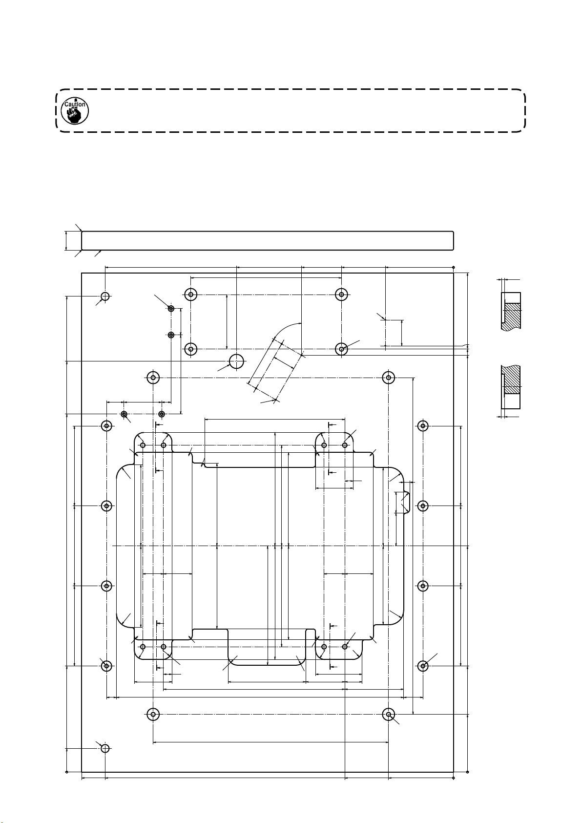
(2) Drawing of the table(Table-xed type)
2X
Ø32
2X(
Ø12
Ø17)
2X(
2X(
2X
Ø6)
Ø12
2X
Ø6
2X
56±1
Ø6)
Ø12
2X(
2X
116±4
-1
+2
23
I
F
Ø
109±1
ZZ
D
H
±1
50
H
3±1
Ø
Ø6)
+2
-1
17
500±1.5
320±1
60°±5°
48.5±1
0
+0.1
0
1
4X
26
+0.1
Ø
4X
30°
Z-Z
4X
55±1
(4箇所)
Z-Z
(4 locations)
ZZ
4X
Ø50
4X(
Ø13)
8±1
4X(
G
Ø9
4X
Ø9)
Ø26
30±2
4X
10±1
277±3.5
(30°)
Ø9)
(4X
1050
1000
928
915
907.5
895
Ø6
80±1
2X
50±4
Ø
80±1
70±1
C
X(R)
2
50±4
Ø6
2X
90±4
±5
100
Ø
±1
±1
368
385
E
486±3.5207±3.5
X
4
Ø13
254±3.5
68±1
250±1
252±1
715±3
670
G 2×ø3.5±0.5 depth 30 (on the bottom surface)
H R2 (all corners)
I Right side
570
530
490
410
370
365
D 4×ø2.5±0.5 depth 30
E 2×ø4.5±0.5 depth 30
F 2×ø4.5±0.5 depth 30
730
B
254±3.5
-1
+2
17
Ø
Z Z
ZZ
Ø9
X
4
80
50
40
A
680
670
615
598
595
555
530
330
260
175
149
118
75
A 2×ø4.5±0.5 depth 30
B 2×ø4.5±0.5 depth 30
C 2×ø3.5±0.5 depth 30 (on the bottom surface)
56
– 4 –
Page 8
(3) Drawing of the table (Semi-sunken type)
In the case the semi-sunken type machine head is used, the kit for semi-sunken type (part number : 40157881)
is required. Prepare the kit simultaneously with the table.
In the case the semi-sunken type machine head is used, the table reinforcing plate (part number:
32080707)(supplied with the kit (part number: 40157881)) has to be installed without exceptions.
(Refer to "3-5.(2) ① Installing the table reinforcing plate" p. 11.)
40±1
1010
872
760
Note) When no
H
H
instruction is given,
740
I
K
±1
170
0
+ 1
1
26 Depth of coun-
terbore
the corner radius
A 4×9 drilled hole
shall be R5.
B 4×8 drilled hole 22
N
±1
56
±1
168
80
±1
37±2
20
±1
F
20
20
R
R
8
R
30
R
±2
173
Y Y
Depth of counter-
8
R
0
+ 1
1
bore
0
+ 1
1
26 Depth of coun-
terbore
hole,depth 20±3
C 4×9 drilled hole
D 4×2.5±0.5 drilled
461
±4
116
M
8
R
±2
176
4×8 drilled hole
E
109±1
D
320
±1
0
+ 1
1
22 Depth of coun-
terbore
60°±5°
297±3
±2
241
±1
214
48.5±1
±2
199
F 2×6 drilled hole
+ 1
12 Depth of coun-
323
8
R
0
1
terbore
G 2×3.5±0.5 drilled
20
R
±1
0
+ 1
1
12 Depth of coun-
N 2×6 drilled hole
terbore
1060
Z-Z
(2カ所)
Z-Z
7
±0.5
hole,depth 20±3
(on the bottom
surface)
R2 (all corners)I Right side
17 drilled hole
H
238
J
145±3
K 17 drilled hole
L 8×10 drilled hole
M 30 drilled hole
G
(2 locations)
C
55±1
YY
20
R
8
R
30
18
±1
80
R
13
8
R
45
8
±2
R
167
905
898
885
Y-Y
(2カ所)
Y-Y
(2 locations)
7
±0.5
±1
170
70
±1
170
61
61
±2
44±144±1
±2
173
30
E
R
8
R
R
21
±1
±1
170
225
ZZ
20
20
R
18
80
±1
±1
±2
176
8
R
20
R
385
±1.5
±2
±1
199
214
±2
±2
241
253
8
R
20
R
20
R
165
±2
610
±2
83
±2
±2
±2
167
ZZ
L
8
R
20
R
99
±1
37
±1
125
±2
±3
715
30
R
B
41
±1
480
±1
170
±1
170
225
122.5
A
500
50
J
740
790
±1.5
231
138
– 5 –
Page 9
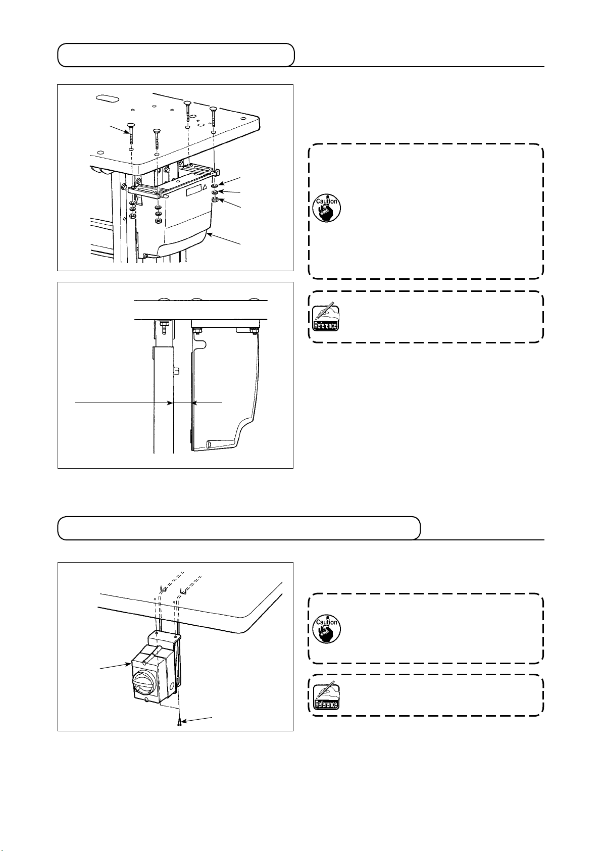
3-2. Installing the control box
❷
❸
❹
❺
❶
Install control box ❶ to the location illustrated in the
gure using four bolts ❷, four plain washers ❸ and
four spring washers ❹ and four hexagonal nuts ❺
supplied with the unit.
1. Install control box ❶ 30 mm or more
away from the stand. If control box ❶ is
located too close to the stand, the for-
mer can get hot or the sewing machine
can malfunction.
2. In the case the semi-sunken type machine head used, install the control box
after carrying out the procedure written
in "3-9. Installing the regulator and the
manifold" p. 20.
Bolt ❷ is a cup head square neck bolt (M8;
Length: 70 mm) and nut ❺ is a hexagonal
nut (M8).
30 mm or more
3-3. Installing and connecting the power switch
1) Installing the power switch
Fix power switch ❶ on the underside of the table with
two wood screws ❷.
In the case the semi-sunken type machine
head used, install the control box after
carrying out the procedure written in "3-9.
Installing the regulator and the manifold"
p. 20.
❶
❷
Wood screw ❷ has the nominal diameter of
5.1 mm and a length of 20 mm.
– 6 –
Page 10
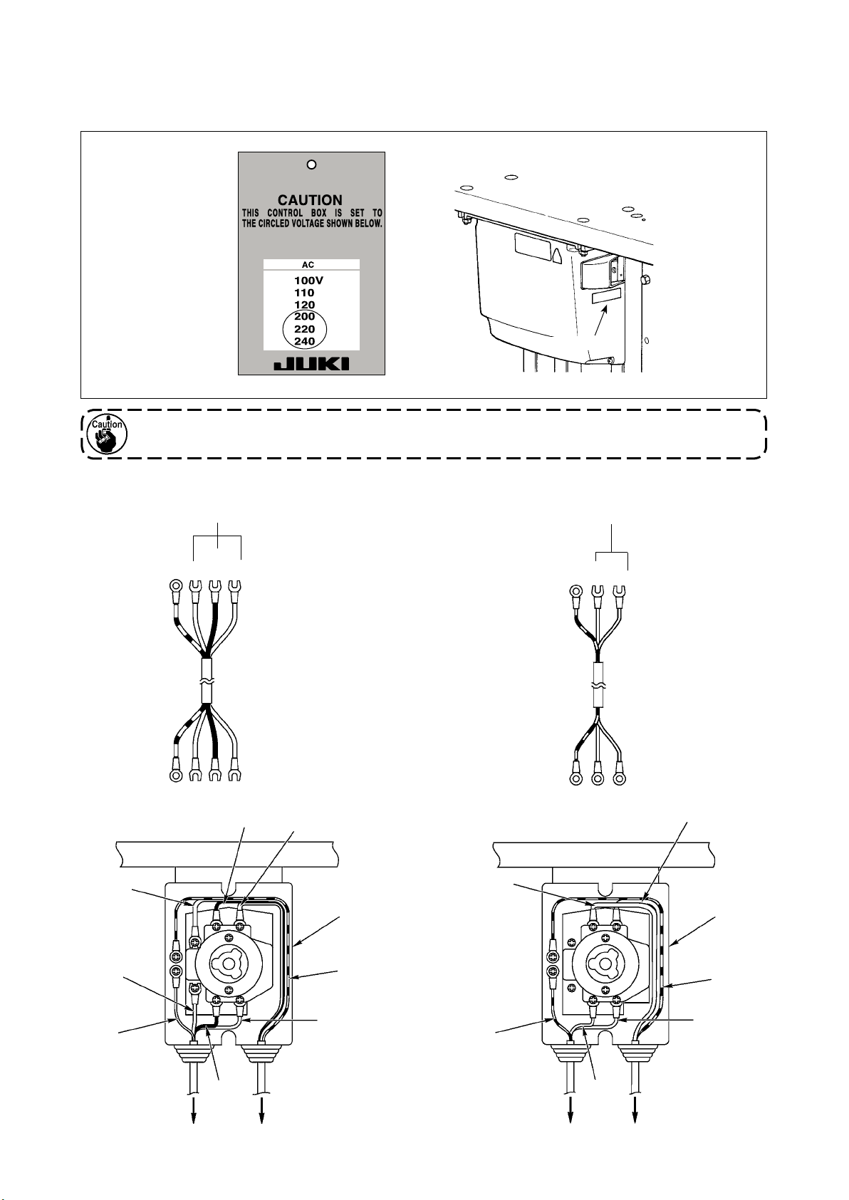
2) Connecting the power cable
Voltage specications are shown on the power indication tag attached on the power cable and on the rating
plate adhered on the power box. Connect the cable which matches the specications.
Power indication tag
Rating plate
(For example: In the case of 200V)
Never use the machine unless the voltage specications described on the power indicator label
are satised.
• Connecting three phase 200V to 240V
AC200 to AC240 V
Green/Yellow
– GND
Table
Red
Black
Red White
Power source cord
Black
Power switch side
Plug side
White
Power switch
• Connecting single phase 200V to 240V
AC200 to AC240 V
Green/Yellow
– GND
Table
Brown
Brown
Light blue
Power source cord
Power switch side
Plug side
Light blue
Power switch
Red
Green
Black
Green/
Yellow
White
PlugControl box
Green/
Yellow
Brown
Control box
Plug
Green/
Yellow
Light blue
– 7 –
Page 11
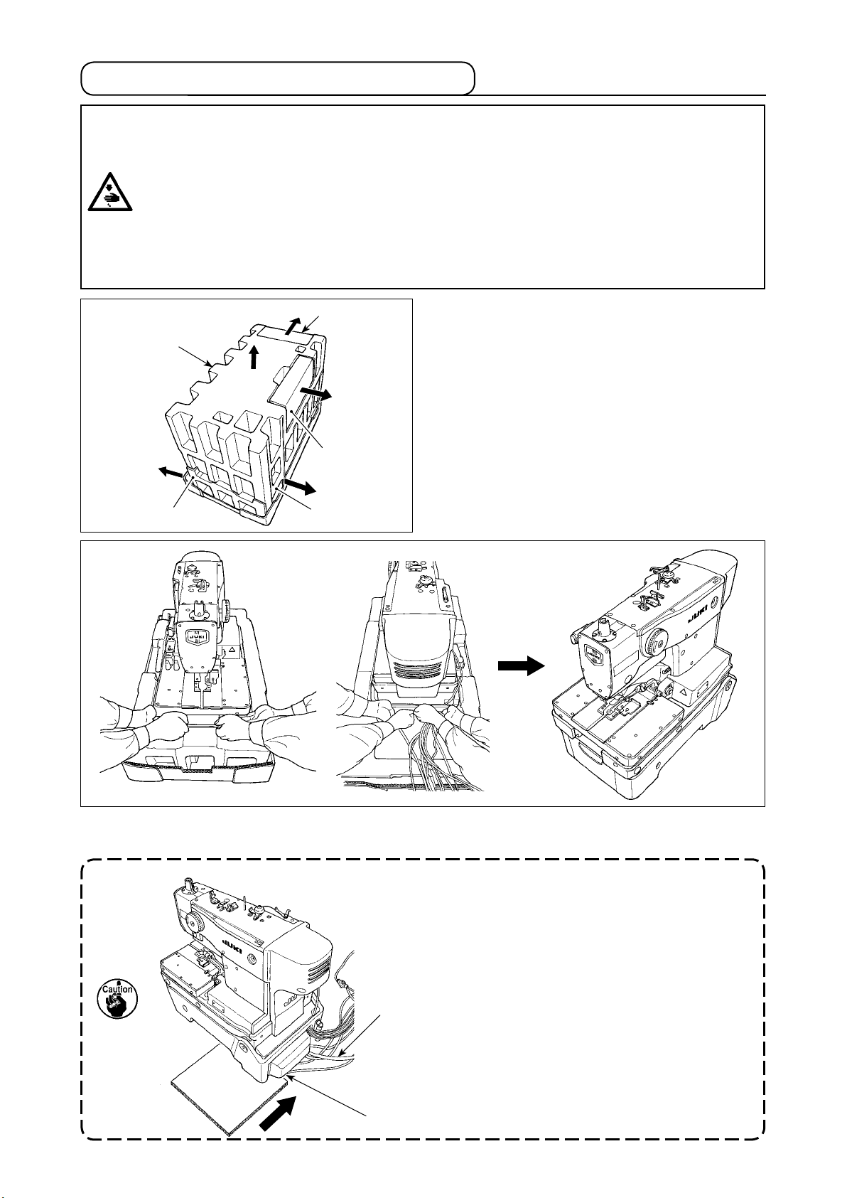
3-4. Taking out the sewing machine
DANGER :
1. The sewing machine should be taken out by a trained technician(s).
2. The sewing machine has a mass of approximately 110 kg. Four or more workers are required
to take out the sewing machine.
4. Never connect the power plug until the installation of the sewing machine is completed in order
3. Do not apply an unreasonable force to the sewing machine until the installation of the sewing machine is completed. If such a force is applied, the sewing machine can lose its balance and can fall
alone or together with the table, resulting in personal injury or sewing-machine breakage.
to protect against an accident due to an abrupt startup of the sewing machine.
❹
❸
❺
❷
1) Remove accessory boxes ❶ and ❷ in the direction
of the arrow.
2) Remove upper foam polystyrene ❸ in the direction
of the arrow.
3) Remove the right and left intermediate foam poly-
styrene ❹ and ❺ in the direction of the arrow.
❶
4) Take out the sewing machine from the package, by four workers, holding the portions illustrated in the gure.
Place it on the oor.
Place a cardboard sheet or packing material between
the oor and the sewing machine in order to avoid
damaging the oor and to prevent the cords from
being pinched between the INT cover and the oor.
Cord
INT cover
– 8 –
Page 12
3-5. Installing the sewing machine
WARNING :
The sewing machine has to be carried by four or more workers.
Carry out the installation work on a level place.
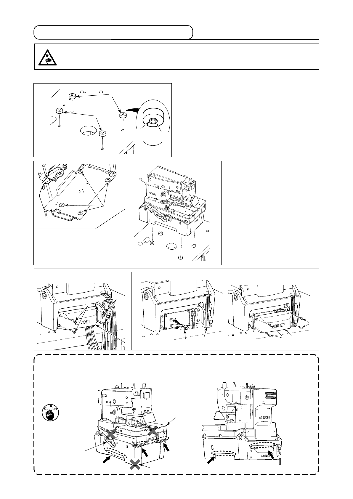
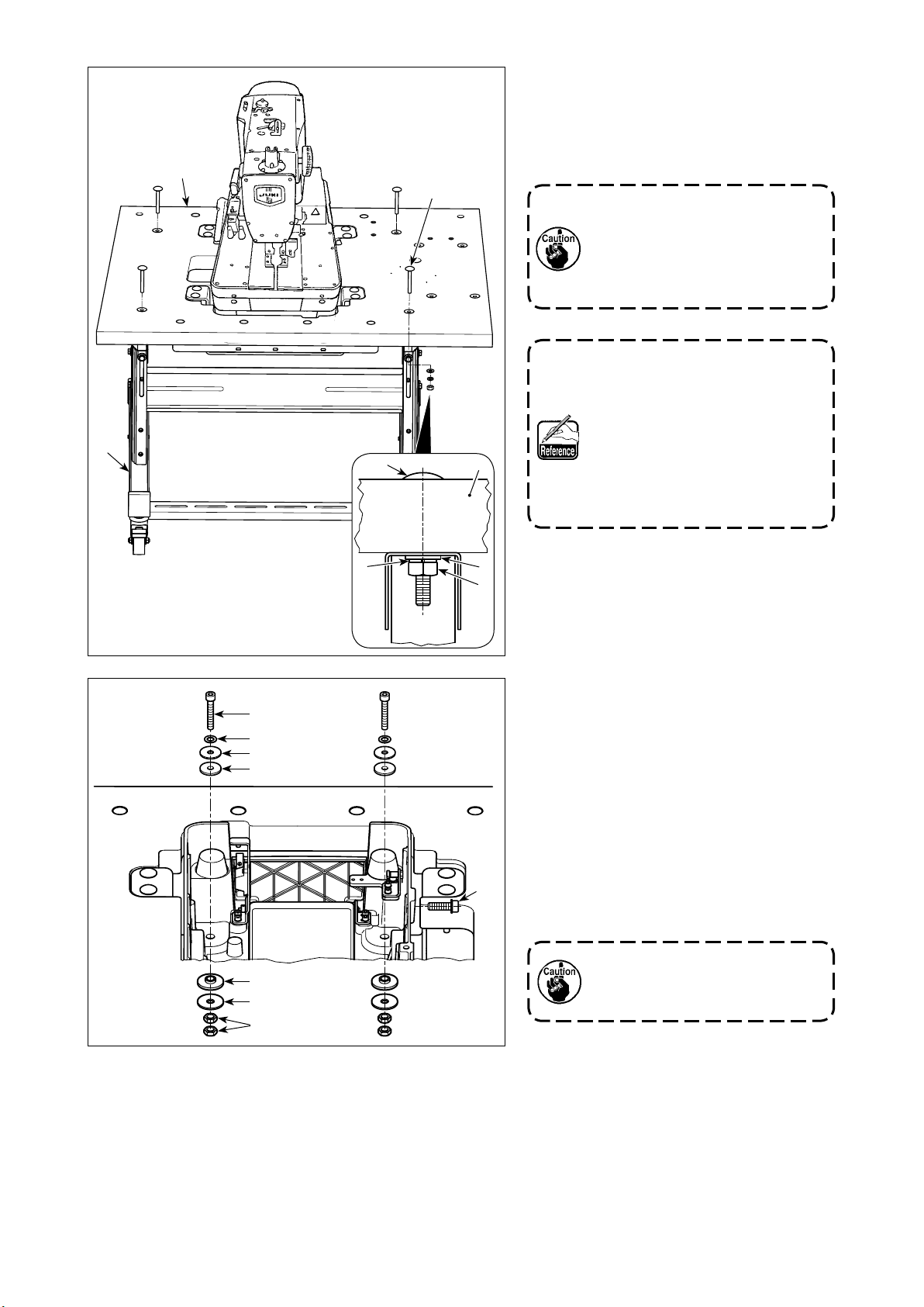
(1) In the case of the table-xed type machine head
1) Remove the paper liners from four bolt rubbers B
❶
❶
❶. Place and adhere the liners over the holes in
the table. (Place the bolt rubber B with its convex
side faced downward.)
1)
2)
3)
❾
Under-
side
Paper
liner
2) Place the sewing machine on
the top surface of the table in
such a way that the concave
sections A of the bottom cover
t on bolt rubbers B ❶.
A
3) Remove four setscrews ❾.
Remove INT cover .
4)
Put air tubes and cords coming
from the sewing machine head
into the hole in the table.
5) Install INT cover with four
setscrews ❾.
4) 5)
❾
❾
Air tube
1. Lift the sewing machine head with four or more people by holding the sections marked with
dotted circle as shown in the gure.
2. Do not hold the underside of hinge stopper, bottom cover, and feed base.
Hinge stopper
Bottom cover
Cord
Feed base
❾
– 9 –
Page 13
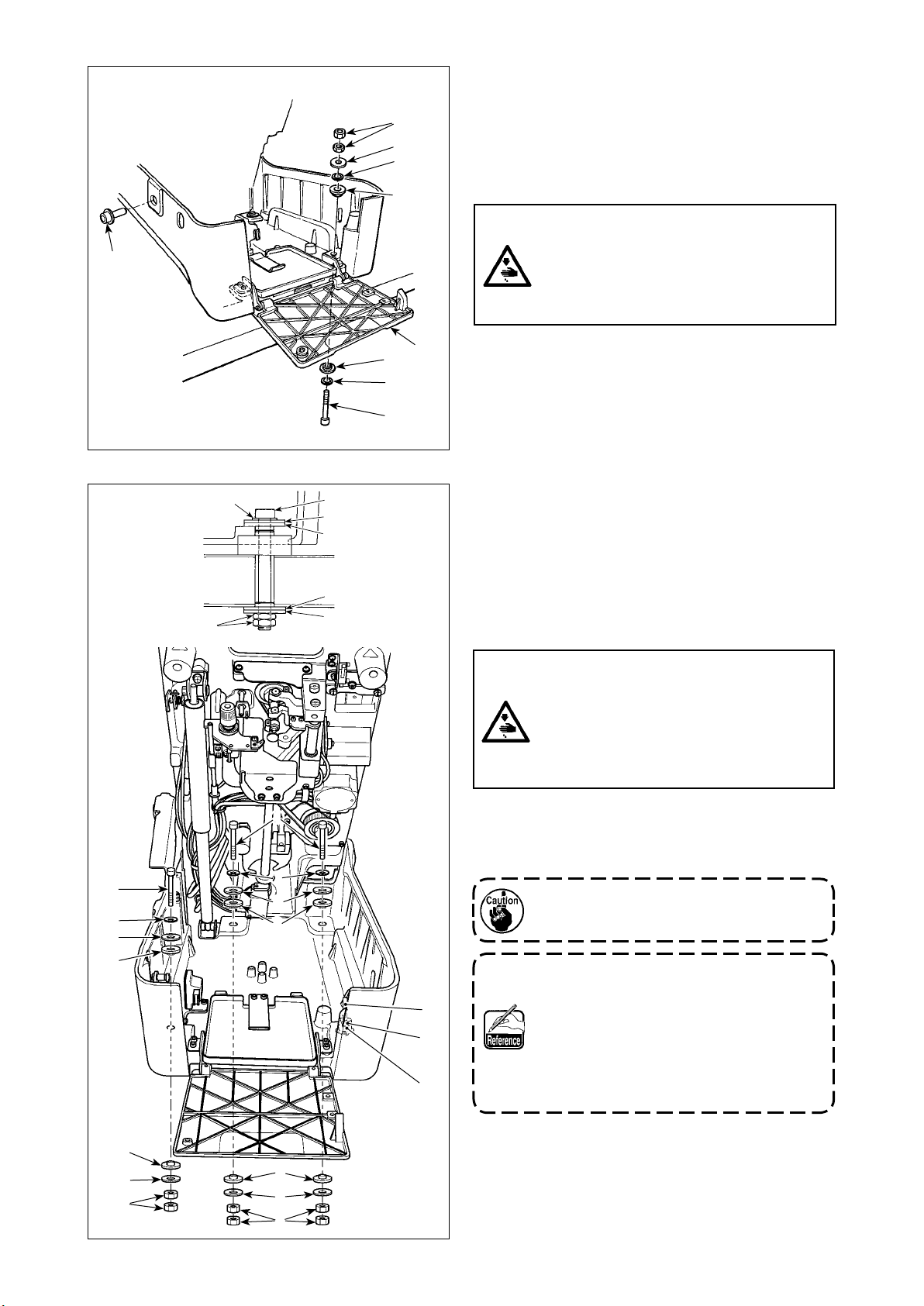
6), 7)
❽
❻
❺
❼
❹
6) Remove machine head xing bolts ❽. Raise the
sewing machine to the 1st step of the hinge stop-
per.
When raising the sewing machine, refer to "3-6.
Raising and returning the sewing machine" p.
16.
WARNING :
Do not raise the sewing machine above
the 1st step of the hinge stopper.
If it is raised above the 1st step, the sewing machine can fall, resulting in personal
injury or sewing machine breakage.
8) to 10)
❻
❼
❺
❹
❸
❹
❺
❺
❹
❸
❷
7) Open front cover ❷. Insert a bolt ❸, a washer ❹
and a bolt rubber ❺ from the right front side of the
sewing machine, and temporarily x them with a
bolt rubber ❺ a washer ❹, a packing ❼ and two
nuts ❻.
8) Be sure to raise the sewing machine to the fourth
step of the hinge stopper.
Fix the sewing machine with remaining three bolts
❸, six washers ❹, six bolt rubbers ❺, three packings ❼ and six nuts ❻.
9) Remove bolt ❸ and two nuts ❻ which have been
used for temporarily xing.
WARNING :
If your body comes in contact with the
corner section of connector cover ❾ of
the lateral-direction motor during work,
unexpected injury can be caused. Be sure
to keep away from the corner section of
the connector cover.
❸
❼
❹
❺
❺
❹
❻
❸
❼
❹
❺
❺
❹
❻
❻
❸
❻
10) Attach bolt ❸ and two nuts ❻ removed in the
above step of procedure in the reverse direction
and x them.
Fix bolt ❸ and nuts ❻ in such a state that
bolt rubber ❺ is slightly squeezed.
1. Keep machine head xing bolt ❽ since
it is necessary when moving the sewing
machine. Whenever you move the sew-
ing machine, be sure to install the head
xing bolt in place.
2. Bolt ❸ is an M8 hexagon socket head
bolt (length: 85 mm). Nut ❻ is an M8 one.
– 10 –
Page 14
(2) In the case of the semi-sunken type machine head
❸
❸
❶
❹
❺
❻
❸
❷
❷
❶
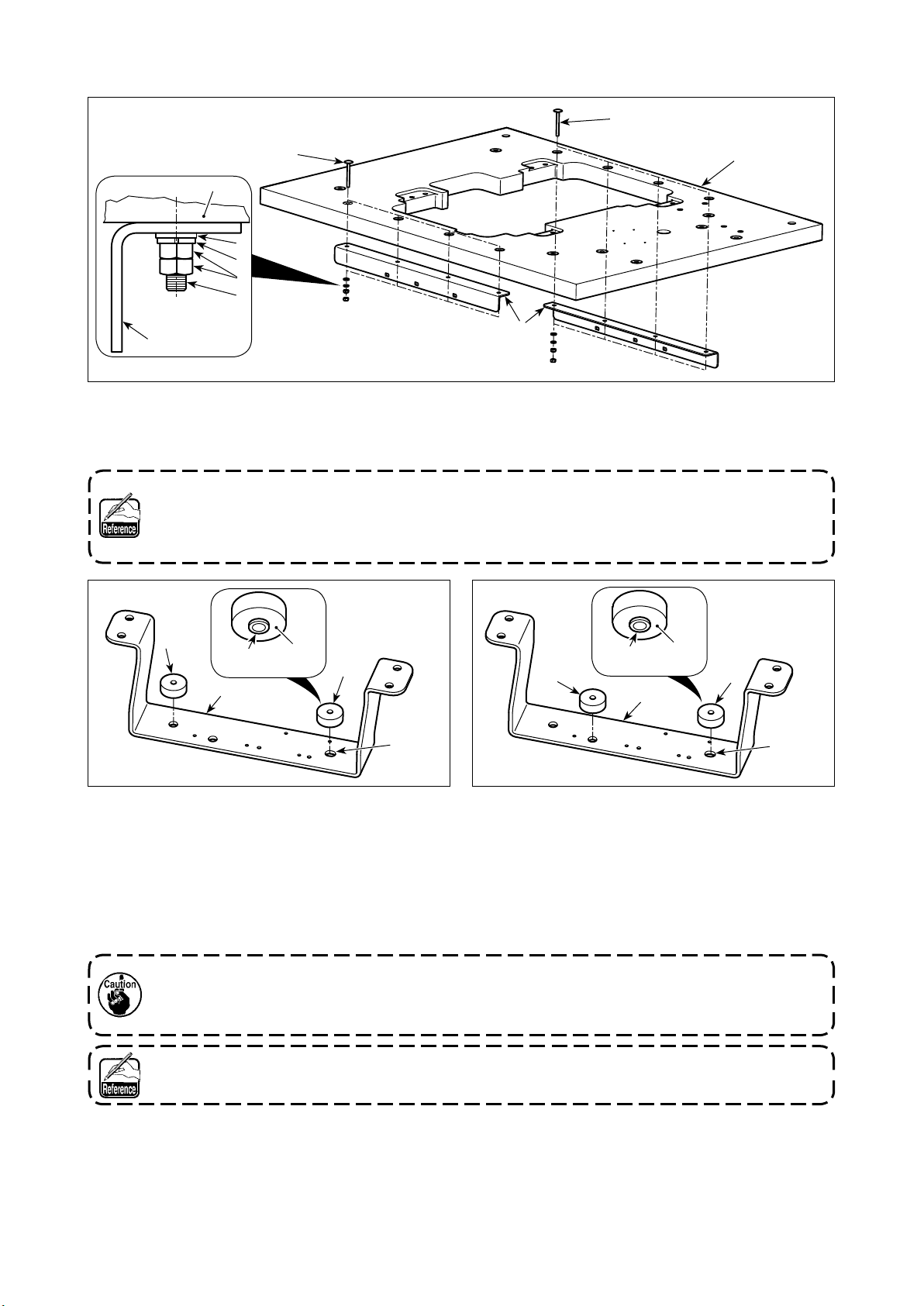
① Installing the table reinforcing plate
1) Fix two table reinforcing plates ❷ on the table ❶ with eight bolts ❸ , eight plain washers ❹ , eight spring
washers ❺ and 16 nuts ❻.
The bolt ❸ is M6 carriage bolt length of which is 60 mm. The dimensions of the plain washer ❹ are
"φ12.5 xφ6.4 x t1.6". Spring washer ❺ is for M6 and nut ❻ is M6 (class 1).
Bolts ❸, plain washers ❹, spring washers ❺ and nuts ❻ are supplied with the kit for semi-sunken
type machine head (part number: 40157881).
❶
Under-
side
❷
Paper
liner
❶
⇦
A
② Assembling the bottom cover stay (front)
1) Remove paper liners ❸ from two bottom rubbers
B ❶ and afx them on bottom cover stay ❷.
* Afx two right-side bottom rubbers B ❶ with shifted
to the left side (in the direction of the arrow) with
respect to slot A in bottom cover stay ❷.
Under-
side
③ Assembling the bottom cover stay (rear)
1) Remove paper liners ❸ from two bottom rubbers
B ❶ and afx them on bottom cover stay ❷.
* Afx two right-side bottom rubbers B ❶ with shifted
to the right side (in the direction of the arrow) with
respect to slot A in bottom cover stay ❷.
❷
Paper
liner
❶❶
⇦
A
1. Insert bottom rubbers B ❶ into the respective holes in bottom cover stay ❷ while holding them
so that their projecting side is faced downward.
2. Carefully check the location of mounting holes in left-side bottom rubbers B ❶.
Bolt rubber B ❶ is the head accessories. In addition, bottom cover stay ❷ are supplied with the kit
for semi-sunken type machine head (part number: 40157881).
– 11 –
Page 15

A
B
❷
❷
❸
❶
❸
❶
④ INSTALLATION
1) Place table ❶, bottom cover stay (front)
❷ and bottom cover stay (rear) ❸ on the
oor.
2) Align bottom cover stay mounting hole A
in table ❶ with mounting holes B for the
respective bottom cover stays.
At this time, the distance between
the respective bottom cover stays
must be 309 mm, and the distance
between bottom cover stay (rear) ❸
and table ❶ must is 81 mm.
❺
309mm
81mm
3) Put the machine head on the bottom cover
stays.
At this time, put the machine head in such
a way that bottom rubber B ❹ ts in de-
pressed portions C in bottom cover ❺.
C
❺
❹
– 12 –
Page 16
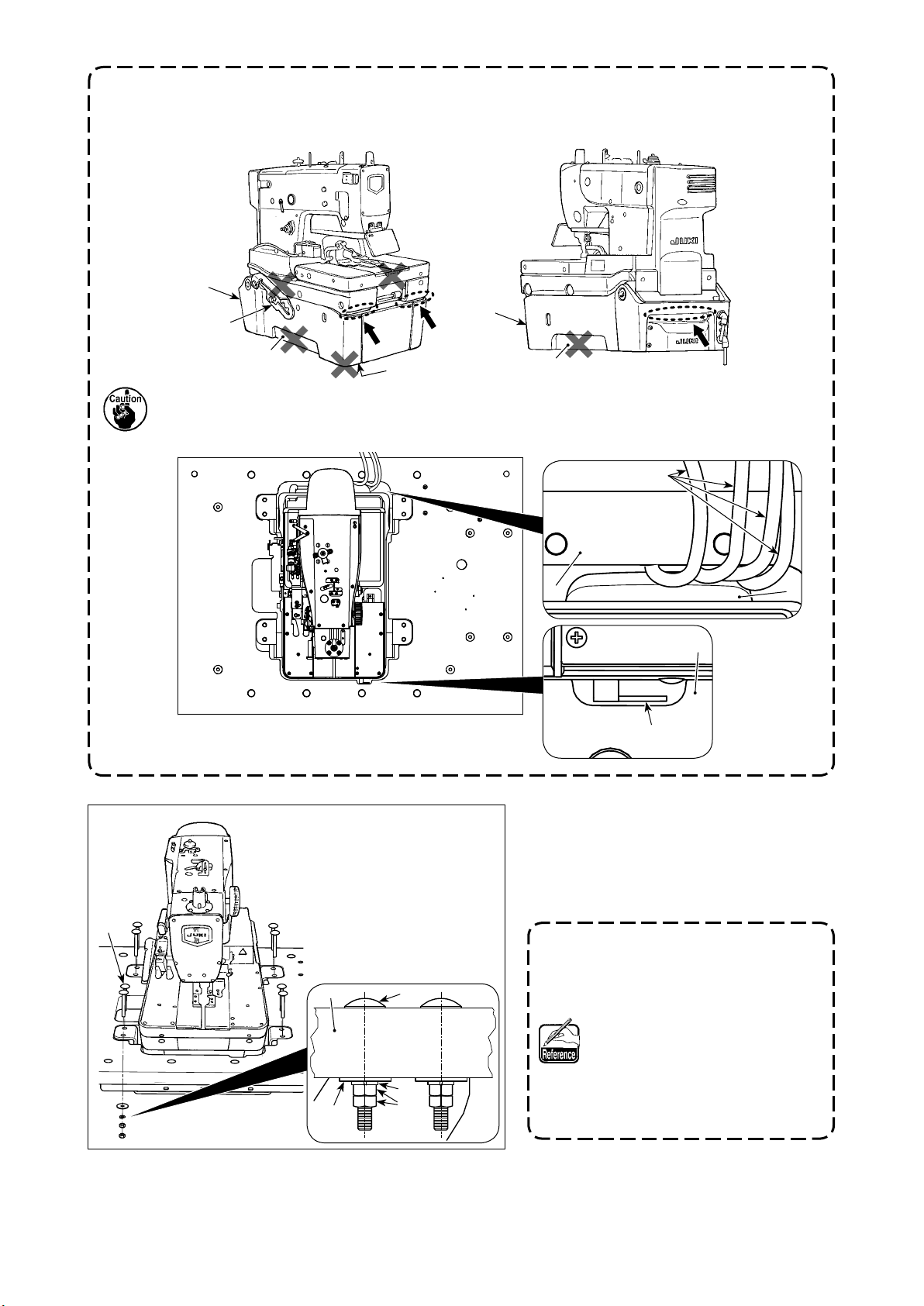
1. Lift the sewing machine head with four or more people by holding the sections marked with
dotted circle as shown in the gure.
2. Do not hold hinge stopper ❻, bottom ❺ of bottom cover D and depressed portion E on the
side face.
❺
❻
❺
E
D
E
3. When putting the machine head on the bottom cover stays, carefully prevent handle ❼ and INT
cover ❽ from coming in contact with table ❶. In addition, do not place the wiring and piping
between INT cover ❽ and table ❶.
Wiring, piping
❶
❶
❼
❽
❾
❾❶
4) Lifting table ❶, join table ❶, bottom cover
stay (front) ❷ and bottom cover stay (rear)
❸ with eight bolts ❾, eight plain washers
, eight spring washers and 16 nuts
.
The bolt ❾ is M8 carriage bolt length
of which is 70 mm. The dimensions
of the plain washer are "φ30
xφ8.5 x t2". Spring washer is for
M8 and nut is M8 (class 1).
Bolts ❾, plain washers , spring
washers and nuts are sup-
plied with the kit for semi-sunken
type machine head (part number:
40157881).
– 13 –
Page 17
❶
❶
5) Holding table ❶ at its four corners with
four or more workers, place it on assembled table stand and x with four bolts
, four plain washers , four spring
washers and four nuts .
1. Lift the table ❶ has to be carried
by four or more workers.
2. Lift the table ❶ while keeping it
in a horizontal position without
tilting.
Bolt is carriage bolt with 18 5/16
threads and is 70 mm long. Plain
washer is of "φ18 xφ8.5 x t1.6".
Spring washer is of "φ15 x φ9 x
t2". Nut has 18 5/16 threads.
Bolt , plain washer , spring
washer , nut is the head acces-
sories.
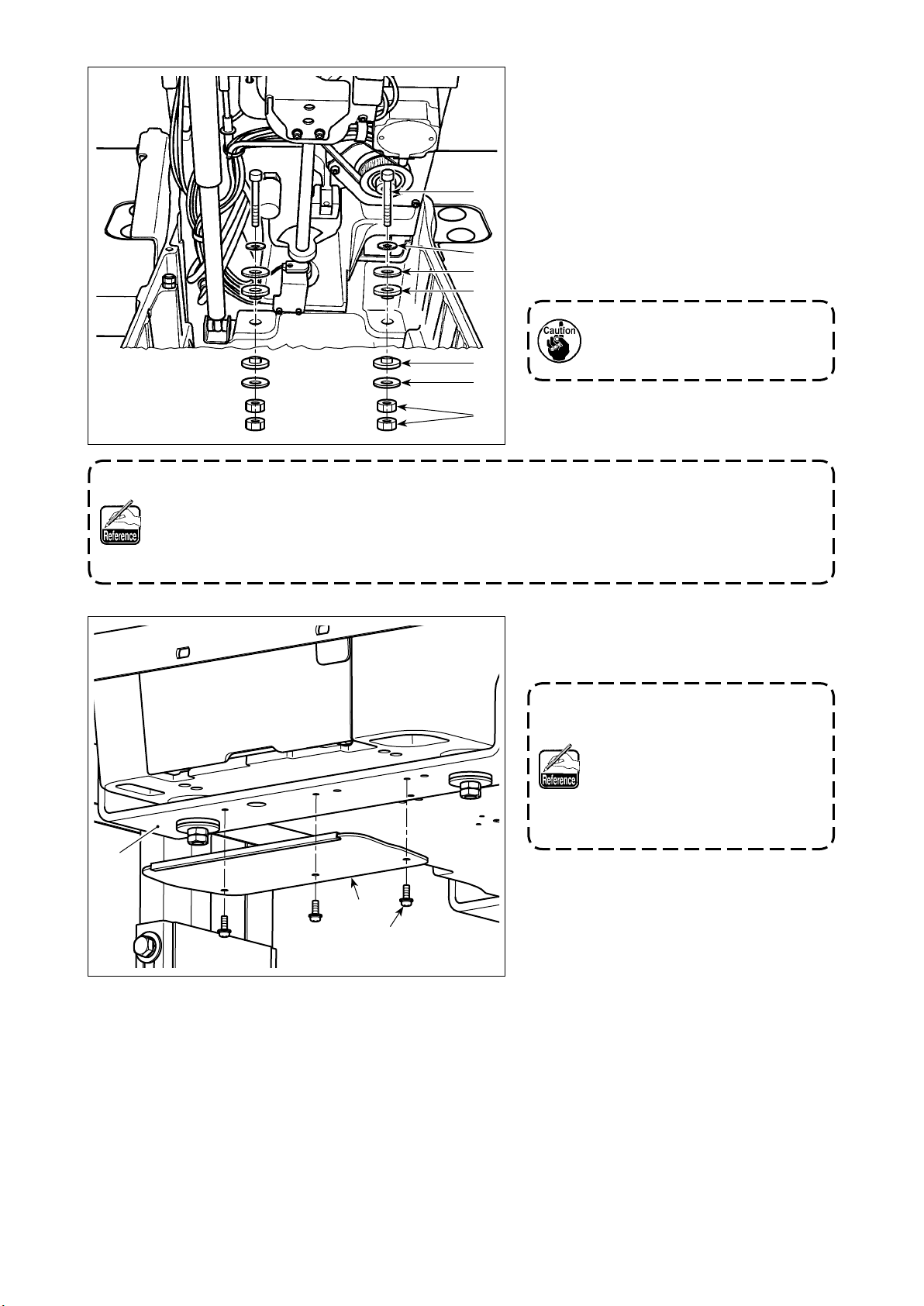
6) Remove machine head xing bolts .
Raise the sewing machine to the 3rd step
of the hinge stopper.
When raising the sewing machine, refer to
"3-6. Raising and returning the sewing
machine" p. 16.
7) Secure the machine head by xing two
bolts , two packings , four plain wash-
ers , four bolt rubbers and four nuts
at two locations on this side of the sewing
machine.
Fix bolt and nuts in such a
state that bolt rubber is slightly
squeezed.
– 14 –
Page 18
8) Raise the sewing machine to the 4th step
of the hinge stopper.
When raising the sewing machine, refer to
"3-6. Raising and returning the sewing
machine" p. 16.
9) Secure the machine head by xing two
bolts , two packings , four plain wash-
ers , four bolt rubbers and four nuts
1. Keep machine head xing bolt since it is necessary when moving the sewing machine. When-
ever you move the sewing machine, be sure to install the head xing bolt in place.
2. The bolt is M8 hexagon socket head screws of which is 50 mm. The dimensions of the plain
washer are "φ30 xφ8.5 x t2" and nut is M8 (class 3).
Bolt , packing plain washer , bolt rubber , nut is the head accessories.
at two locations on far side of the sewing
machine.
Fix bolt and nuts in such a
state that bolt rubber is slightly
squeezed.
❷
10) Secure tray on bottom cover stay (front)
❷ with three setscrews .
Setscrew is an M4 round head
screw with washer and has a length
of 12 mm.
Tray and setscrews are sup-
plied with the kit for semi-sunken
type machine head (part number:
40157881).
– 15 –
Page 19
3-6. Raising and returning the sewing machine
DANGER :
1. Do not lift the sewing machine for any purpose other than for installation, repair or adjustment
in order to prevent accidents resulting in personal injuries due to pinching. In addition, the
sewing machine has to be lifted for repair or adjustment only by a maintenance technician
who is familiar with the machine.
2. If you nd the sewing machine is too heavy to lift, the gas spring may have malfunctioned
due to outgassing.
Never lift the sewing machine in such a state since the machine can drop to pinch hands,
ngers and arms resulting in serious injury.
* Carefully read the description given in "10-14. (6) Standard of replacing time of the gas spring"
p.94 and "10-14. (7) Replacing the gas spring" p.95.
3. Be sure to carry out the work while strictly observing the following in order to protect against
serious injury to hands, ngers and/or arms due to pinching in the relevant parts of the sewing
machine.
• Be sure to hold the sewing machine by the ribs located on the front side of the bed.
•
Be sure to securely x the sewing machine in the raised position by locking the hinge stopper.
4. Do hole hold any part other than the ribs located on the front side of the bed.
5. If you raise the sewing machine with the feed base remained this side, the feed base can move
to pinch hands and ngers resulting in an unexpected injury.
WARNING :
When raising/returning the sewing machine from/to its home position, check to be sure that the
sewing machine is locked by the support shaft in the stop position of each step of the hinge stopper.
The sewing machine can be raised/returned to/from four different heights.
1st step 2nd step
3rd step
4th step
– 16 –
Page 20
❹
❼
❻
❷
❺
❽
❸
❶
❷
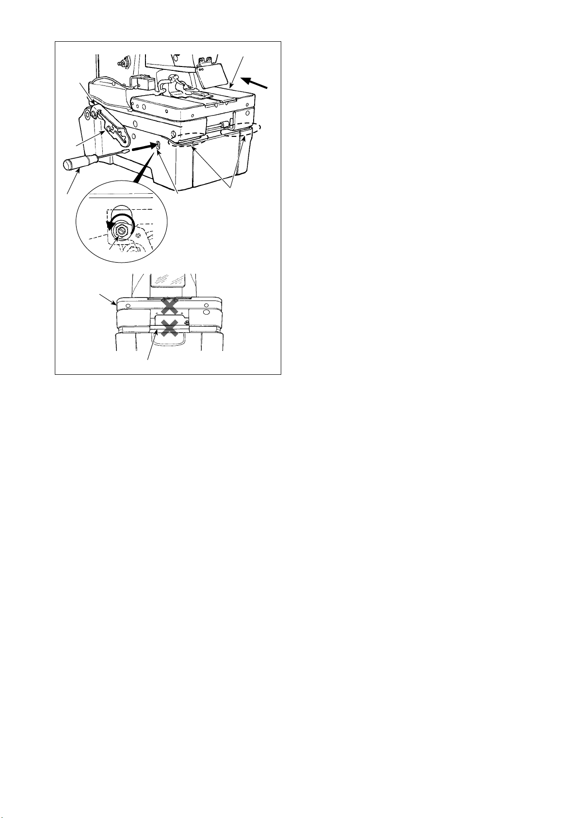
1) To raise the sewing machine, rstly push feed
base ❷ away from you (in the direction of the
arrow), then insert at-blade screwdriver ❹ into
bottom-cover opening tool slot ❸, turn it counter-
clockwise to release the sewing machine up/down
lock ❺.
2) Turn at-blade screwdriver ❹ to keep the lock
in the released state, and slightly lift the sewing
machine by holding it by rib ❶ located on the front
side of the bed.
3) Carefully remove at-blade screwdriver ❹. Hold
ribs ❶ located on the front side of the bed with
your both hands to slowly lift the sewing machine
to the 1st step of hinge stopper ❻.
At this time, do not hold feed base ❷ and feed
guide shaft ❽.
4) Check to be sure that hinge stopper ❻ is locked
by support shaft ❼. Then, take hands off the ribs.
5) To raise the sewing machine to the 1st to 3rd steps
of the hinge stopper, hold ribs ❶ located on the
front side of the bed with your both hands to slowly
lift it to the required step of the hinge stopper.
– 17 –
Page 21

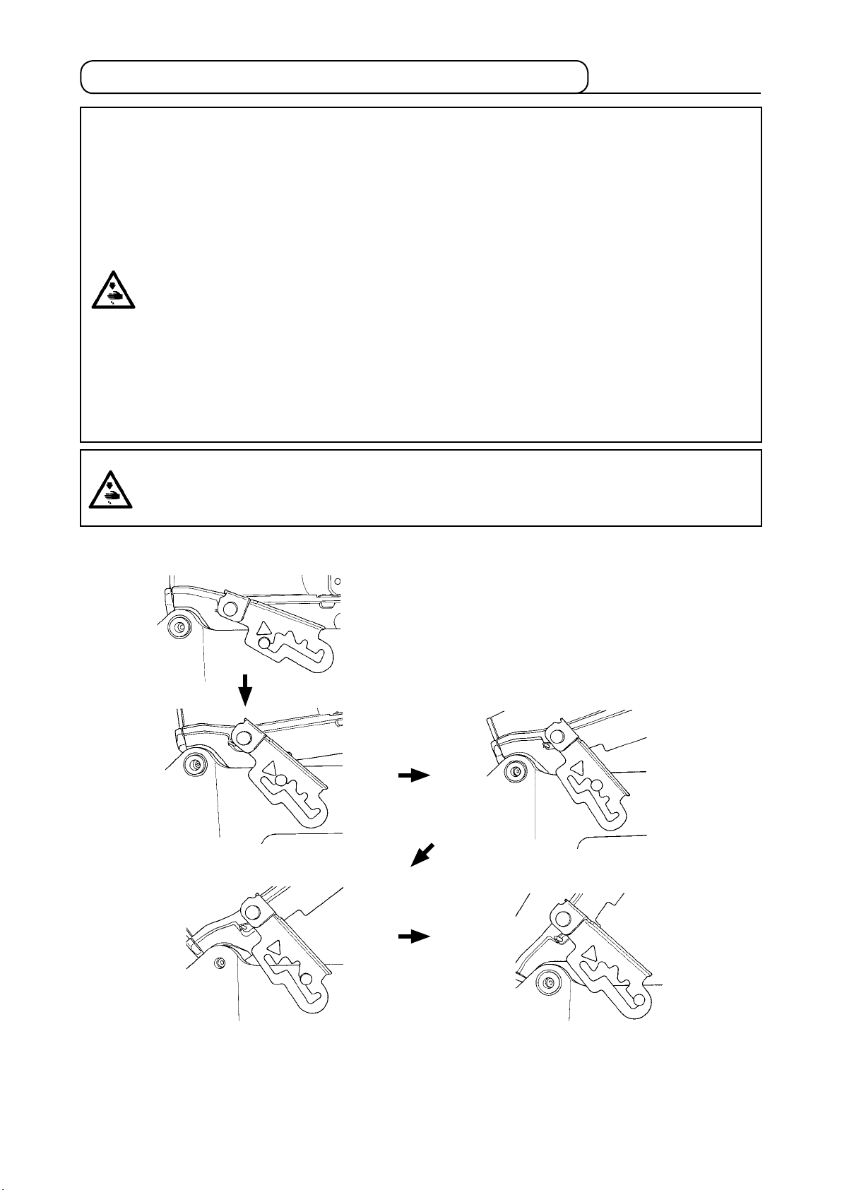
[To lift the sewing machine from the 3rd to 4th step of the hinge stopper]
6) Hold rib ❶ located on the front side of the bed with your right hand to draw hinge stopper ❻ in direction of
arrow A until the lock is released. Then, slowly lift the sewing machine.
7) Hold ribs ❶ located on the front side of the bed with your both hands to slowly lift the sewing machine to
the 4th step of hinge stopper ❻.
❶
❶
❻
A
❷
❽
❶
8) To return the sewing machine to its home position, rstly check to be sure that there is no tool such as a
screwdriver inside the bottom cover.
9) Hold rib ❶ located on the front side of the bed with your right hand to slightly lift the sewing machine. Then,
hold handle ❻ of the hinge stopper with your left hand and pull it toward you (in direction A) until the lock
is released, then slowly lower the sewing machine.
10) Take your left hand off the stopper section. While supporting ribs ❶ located on the front side of the bed
with your both hands, lower the sewing machine further.
DANGER :
1. Do not lower the sewing machine while keeping pulling the hinge stopper in direction A, in
order to prevent pining of ngers, hands and arms under the sewing machine leading to a
serious injury. (Be sure to take your hands off the hinge stopper.)
2. Do not hold feed base ❷ and feed guide shaft ❽.
11) At its each step, the hinge stopper is locked to secure the sewing machine at the corresponding height.
Following the procedure described in 9), hold rib ❶ on the front side of the bed with your right hand to
slightly lift the sewing machine. Then, hold the handle of the hinge stopper with your left hand to release
the lock and slowly lower the sewing machine.
12) The sewing machine is stopped again at the nal step of its lowering for the sake of safety. Following the
procedure described in 9), hold rib ❶ on the front side of the bed with your right hand to slightly lift the
sewing machine. Then, hold the handle of the hinge stopper with your left hand to release the lock and
slowly lower the sewing machine.
DANGER :
Take care to prevent pinching of hands and ngers between the sewing machine and the bottom
cover. It should be strictly prohibited to lower the sewing machine by two or more workers while
holding it by any section other than the ribs located on the front side of the bed since it can cause
a pinching accident resulting in a serious injury to hands, ngers and/or arms.
– 18 –
Page 22
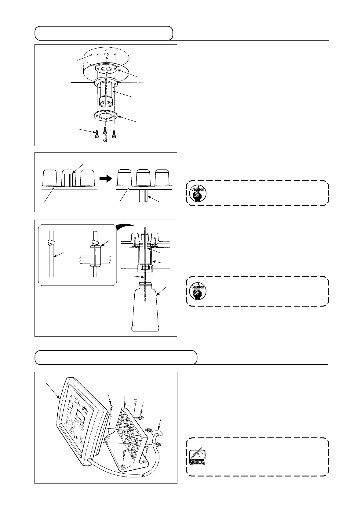
3-7. Installing the poly oiler
❺
❷
❶
❸
❹
❼
❺
❺
1) Place the sewing machine in its home position.
2) nstall oil drain cock ❶, oil seal ❷ and washer ❸
on bottom cover ❺ with four setscrews ❹.
3) Raise the sewing machine.
4) Drive spring pin ❼ of bottom cover ❺ into bottom
cover ❺ until it is almost ush with bottom cover
❺.
Take care not to crack bottom cover ❺ when
driving in spring pin ❼.
❼
❼
❻
❻
❼
❶
❽
3-8. Installing the operation panel
❺
❷
❶
❸
❹
5)
Make a knot in the oil wick ❻ (ø2.5 mm). Insert oil
wick ❻ (ø2.5 mm) into spring pin ❼ of bottom cover
❺ until its end comes from oil drain cock ❶.
At this time, insert oil wick ❻ (ø2.5 mm) supplied
as accessories into the slit in spring pin ❼.
6) Install poly oiler ❽ on oil drain cock ❶.
Refer to "3-6. Raising and returning the
sewing machine" p. 16 when you raise or
return the sewing machine.
1) Fix operation panel installing plate ❶ on the table
at a desired location near its right end with four
wood screws ❷.
2) Put the cable of operation panel ❺ through hole
❹ in the table.
3) Fix operation panel ❺ on operating panel mounting
plate ❶ with three setscrews ❸.
Wood screw ❷ has the nominal diameter
of 3.8 mm and a length of 20 mm. Setscrew
❸ is an M4 round head screw with washer
and has a length of 16 mm.
– 19 –
Page 23
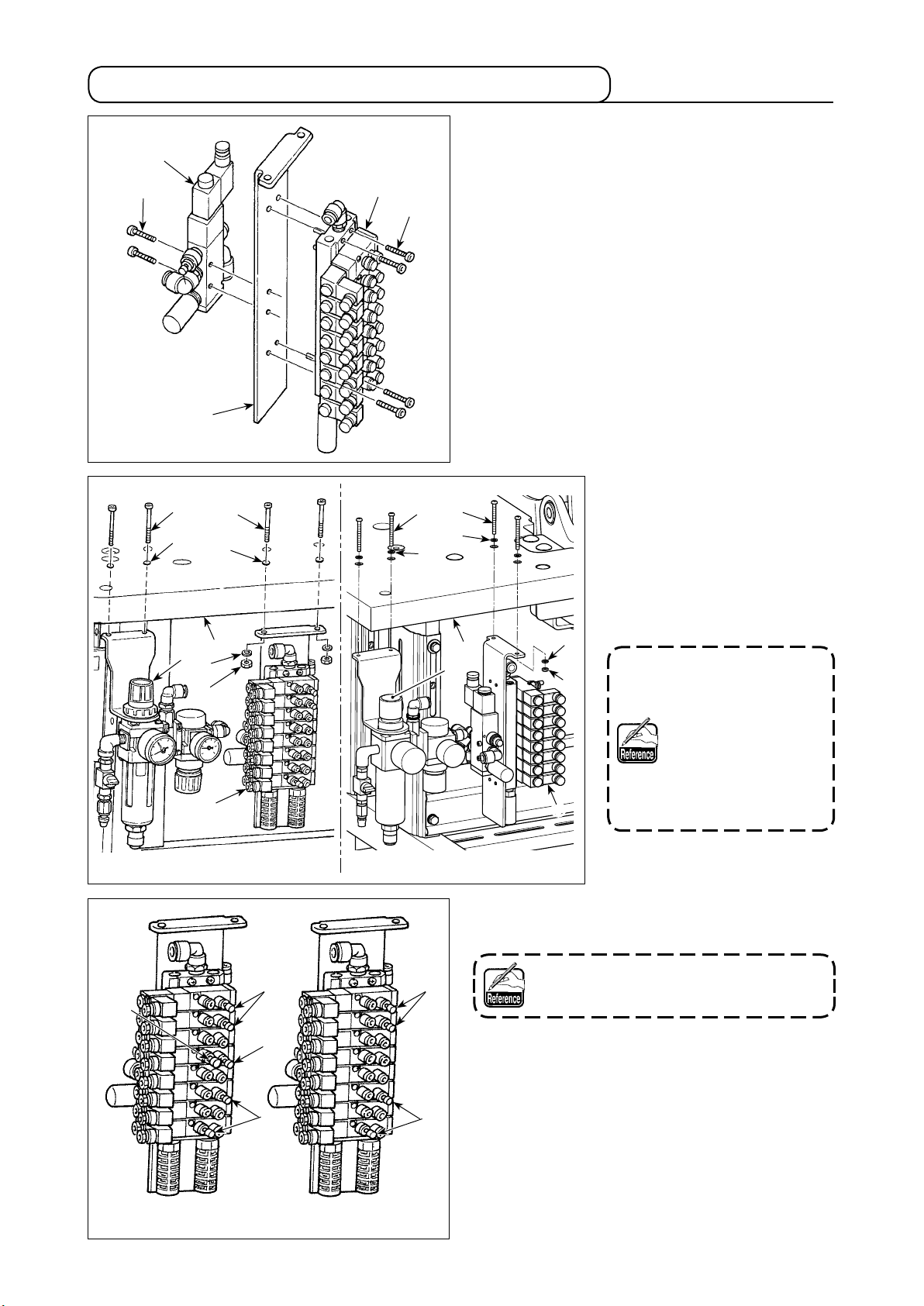
3-9. Installing the regulator and the manifold
1) Install manifold asm. on manifold mounting plate
❾ with four setscrews .
2) Install solenoid valve on manifold mounting
plate ❾ with two setscrews .
❸
❹
❾
❼
❻
❸
❹
❻
❼
3) Install regulator asm. ❶ on
table ❷ with two setscrews
❸ and two washers ❹.
4) Install manifold ❺ on table ❷
with two setscrews ❻, four
washers ❼ and two nuts ❽.
❷
❶
❼
❽
❺
Table-xed type Semi-sunken type
❷
❶
5) Attach plugs and to manifold asm. at the
locations shown in the gure at left.
Plug is for ø4 hole and plug is for ø6
❺
hole.
❼
❽
Setscrews ❸ and ❻
are pan head screws
M5 of length 50 (mm).
Setscrews and are
hexagon socket head
screws M4 of length
30. Nuts ❽ are hexagon
nuts M5.
00 type 01 type
– 20 –
Page 24
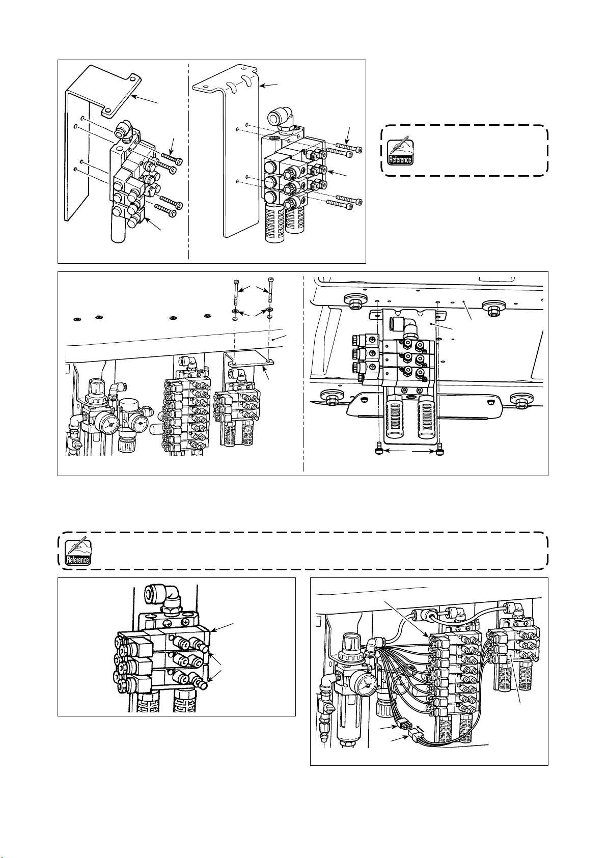
[For the needle thread clamp unit]
❷
❸
❶
❷
1) Install manifold asm. ❶ for the
needle thread clamp on manifold
mounting plate ❷ with four setscrews ❸.
❸
Setscrew ❸ is M4 hexa-
gon socket head screws of
which is 30 mm.
❶
Table-xed type
Table-xed type
Semi-sunken type
❺
❽
❹
❷
❷
❼
Semi-sunken type
❻
2) For the table-xed type machine head, install manifold mounting plate ❷ which has been assembled in 1)
on table ❹ with two setscrews ❺ and two washers ❽. For the semi-sunken type machine head, install it
on bottom cover stay (rear) ❻ with two setscrews ❼.
Setscrew ❺ is M5 50-mm long pan head screw. Setscrew ❼ is M5 12 mm long pan head screw with
washer.
❶
❾
3) Attach plug ❾ to manifold asm. ❶ for the needle
thread clamp at the locations shown in the gure
at left.
For one of plugs ❾, remove No. 39 of the manifold
asm. and attach the plug instead. (Pipe is connect-
ed to No.39.)
– 21 –
❶
A
B
4) Connect connector A of standard manifold and
connector B of manifold asm. ❶ for the needle
thread clamp.
Page 25
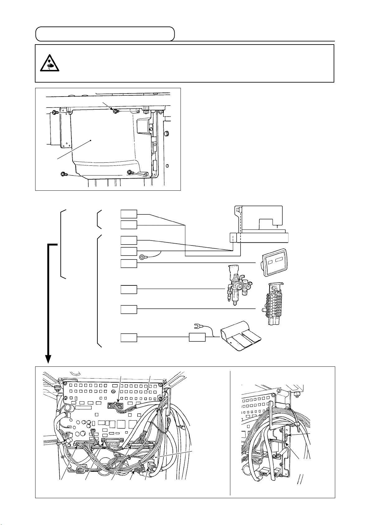
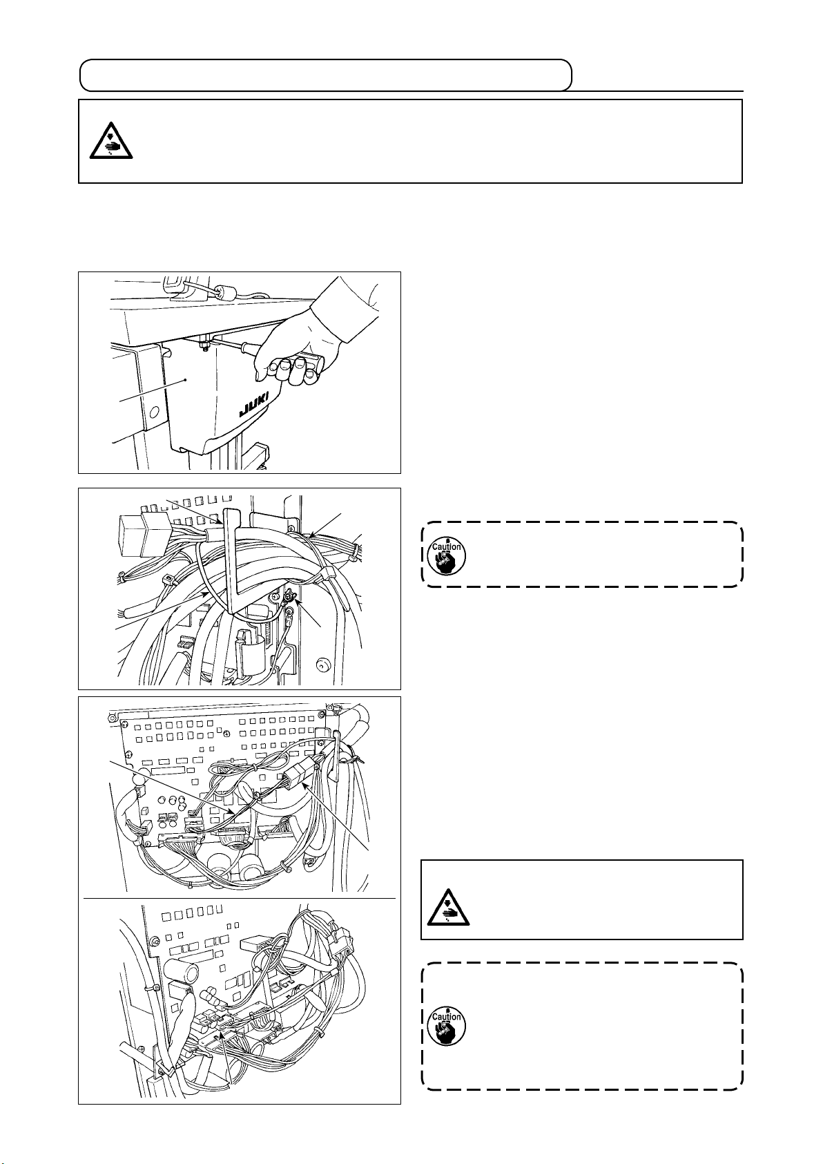
3-10. Connecting the cords
DANGER :
To prevent personal injuries caused by electric shock hazards or abrupt start of the sewing
machine, carry out the work after turning OFF the power switch and a lapse of 5 minutes or more.
To prevent accidents caused by unaccustomed work or electric shock, request the electric expert
or engineer of our dealers when adjusting the electrical components.
❷
❶
1) Loosen four setscrews ❷ of control box cover ❶.
Remove control box cover ❶.
2) Connect the cords to the respective connectors
on MAIN PWB, SDC PWB. (Fig. 1)
3) Fix the shielded ground wire of the INT PCB signal
cord at location A of the control box with a screw.
(Fig. 2)
SDC PWB
MAIN PWB
CN15
CN17
CN30
CN45
CN34
CN35
CN44
CN43 9P
CN30 White
9P
4P
16P
50P
26P
3P
30P
White
White
White
Brown
Gray
White
Blue
Red
MAIN PWB
Sewing
machine head
Operation
panel
Air
switch
Solenoid
valve
10P
Foot pedal switch
(Option)
CN44
Blue
CN34
Gray
CN45
Brown
CN17
White
CN15
White
(Fig. 1)
– 22 –
A
SDC PWB
Shielded
ground wire
(Fig. 2)
Page 26

3-11. Handling the cords
DANGER :
To prevent personal injuries caused by electric shock hazards or abrupt start of the sewing
machine, carry out the work after turning OFF the power switch and a lapse of 5 minutes or more.
To prevent accidents caused by unaccustomed work or electric shock, request the electric expert
or engineer of our dealers when adjusting the electrical components.
❶
❷
1) Bring the cords under the table into the control box.
2) Put the cord brought into the control box through
cord exit plate ❶ and x cable clip band ❷.
❸
3) Install control box lid ❸ with four setscrews ❹.
❹
– 23 –
Page 27
3-12. Installing the foot pedal switch (optional)
DANGER :
To prevent personal injuries caused by electric shock hazards or abrupt start of the sewing
machine, carry out the work after turning OFF the power switch and a lapse of 5 minutes or more.
To prevent accidents caused by unaccustomed work or electric shock, request the electric expert
or engineer of our dealers when adjusting the electrical components.
The hand switch is provided on the standard type machine.
To use the optional foot pedal switch (part number: 40033831), connect it in the procedure described below.
When installing the foot pedal switch, the foot pedal switch junction cable asm. (part number: 40114433) is
also required. Refer to "11-6. Others" p. 98.
1) Loosen the four setscrews in the control box to
remove cover ❶.
❶
❹
❷
❸
2) Fix earthing wire ❷ of the foot pedal switch at
❺
A
location A of the control box.
Pass the earthing wire through cord exit
plate ❸. If not, it can be caught under the
cover when closing it.
3) Connect foot pedal switch junction cable ❹ to the
foot pedal switch cable (B) and connect the oppo-
site side of the junction cable to CN43 connector
on the PWB (C).
4) Fix the cable.
Loosen cable clip band ❺. Fix the foot pedal switch
cables (excluding earthing wire ❷) by means of
cable clip band ❺ together with other related ca-
B
bles.
DANGER :
It is very important to carefully connect the
cables to the correct connectors on the
PWB. Wrong connection poses a great risk.
Even in the case the optional foot pedal
switch is installed on the sewing machine,
the hand switch is still enabled. Carefully
operate the switches since the sewing
machine is activated by operating either
switch.
C
– 24 –
Page 28
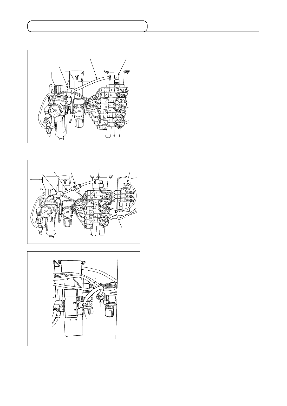
3-13. Connecting the air supply
(1) Connecting the regulator and the manifold
❸
❶
[For the needle thread clamp]
❶
❸
❹
❷
❷
❻
1) Connect joint ❶ of the regulator and joint ❷ of the
manifold by means of the air tube ø10 ❸.
1)-1. Connect air tube ø10 ❸ and joint ❷ of the manifold by means of T-joint ❹ which has a short air
tube.
1)-2. Connect T-joint ❹ and joint ❻ of the manifold
for the needle thread clamp by means of air tube
ø10 ❼.
❾
❼
2) Connect joint ❽ of the cloth trimming regulator
and joint ❾ of the cloth trimming solenoid valve
by means of the air tube ø10 ❺.
❺
❽
– 25 –
Page 29
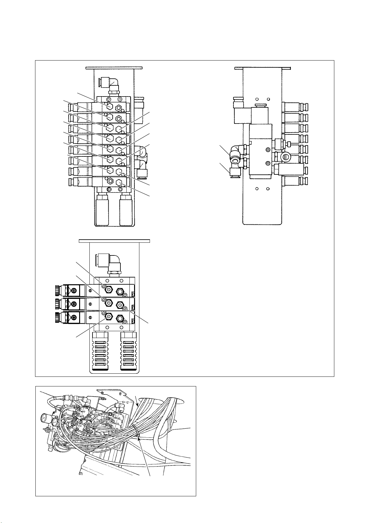
(2) Connecting the air tubes
Connect the respective air tubes coming from the sewing machine head to the respective solenoid valves
matching their numbers correspondingly.
No.1
No.2
No.3
No.5
No.7
No.9
No.10
No.4
No.6
No.8
No.39
(In the case of the
needle thread clamp)
No.11
No.12
[In the case of the needle thread clamp unit]
No.35
No.36
No.15
No.16
No.38
No.37
Cable
Cable clip band (L150) supplied
with the unit as an accessory
After the connection of the respective air tubes,
neatly bundle the cables etc. coming from the
sewing machine with the cable clip band sup-
plied with the unit as an accessory.
– 26 –
Page 30
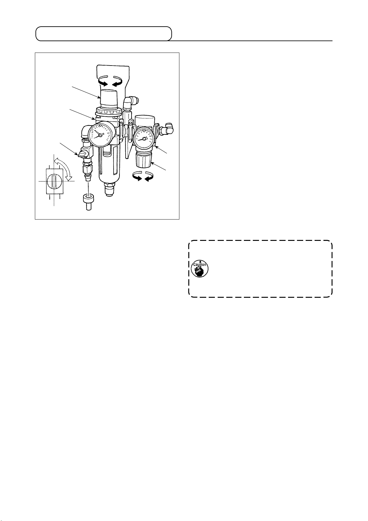
3-14. Installing the air hose
❸
❷
❶
Open
Close
❺
❹
■ Connecting the air hose
Connect the air hose to the regulator using the
hose band and quick-coupling socket joint supplied
with the unit.
■ Adjusting the air pressure
Open air cock ❶.
[Main regulator]
Pull up and turn air pressure regulating knob ❸ of
main regulator ❷ to adjust the pneumatic pressure
to 0.5 MPa. Then, push down the knob to x it.
[Regulator for cloth trimming knife pressure]
Pull down air pressure regulating knob ❺ of reg-
ulator ❹ for the cloth trimming knife pressure and
turn it to adjust the air pressure to 0.35 MPa. Then,
push up the knob to x it.
(The air pressure of the cloth trimming knife can be
adjusted in the range of 0.2 to 0.4 MPa by means
of regulator ❹.)
Regulator ❹ for the cloth trimming knife has
been factory-adjusted to 0.35 MPa. Do not
increase the air pressure unless it is really
necessary. Increased air pressure can cause
a decrease in sharpness of the knife and/or
knife breakage.
After the completion of the respective air pressures
adjustment, close air cock ❶ to remove air. Then,
re-open the air cock to adjust the respective air
pressures.
* The air is removed by closing air cock ❶.
– 27 –
Page 31

3-15.
Cautions for the compressed air supply (source of supply air) facility
As large as 90 % of failures in pneumatic equipment (air cylinders, air solenoid valves) are caused by "con-
taminated air."
Compressed air contains lots of impurities such as moisture, dust, deteriorated oil and carbon particles. If
such "contaminated air" is used without taking any measures, it can a cause of troubles, inviting reduction in
productivity due to mechanical failures and reduced availability.
Be sure to install the standard air supply facility shown below whenever the machine provided with pneumat-
ic equipment is used.
Standard air supply facility to be prepared by the user
Air compressor
After cooler
Auto-drain
Air tank
Main line lter
Auto-drain
Air dryer
Mist separator
Filter regulator
Air solenoid valve
Quality of the air supply
When the supply air contains a considerable amount of moisture
Ambient environment
When our machine is installed at a place where the temperature greatly
changes in the morning and in the evening from that in the daytime or
freeze is like to occur
In the aforementioned cases, be sure to install an air dryer.
When the supply air contains a considerable amount of carbon and dust
(Most troubles in the air solenoid valves are caused by carbon.)
Be sure to install a mist separator.
Standard equipment supplied by JUKI
Air cylinder
Cautions for main piping
• Be sure to slope main piping by a falling gradient of 1 cm per 1 m in the direction of air ow.
• If the main piping is branched off, the outlet port of the compressed air should be provided at the
top part of the piping using a tee in order to prevent drain settling inside the piping from owing
out.
• Auto drains should be provided at all lower points or dead ends in order to prevent the drain from
settling in those parts.
– 28 –
Page 32

3-16. Installing the thread stand
1) Assemble the thread stand asm. and install it in the hole in the rear left part of the table.
2) Tighten locknut ❶ so that the thread stand is xed.
❶
– 29 –
Page 33

3-17. Installing the thread guides
❷
❶
❶
1) Remove two thread guide plates ❶ and setscrew
❷.
2) Reverse one of thread guide plates ❶. Install the
thread guides so that they turn by approximately
40° to allow the thread to pass smoothly.
40° 40°
❹
❸
❺
3) Install thread guide bar ❸.
At this time, install thread
guide bar ❸ so that hole
❹ in thread guide bar ❸
is oriented to hole ❺ in the
AT thread guide.
❹
– 30 –
Page 34

3-18. Installing the eye protection cover and the nger guard
DANGER :
The eye protection cover and the nger guard are used to protect eyes against ying broken needle.
Be sure to use the sewing machine with them installed without exceptions.
1) Assemble nger guard ❶ to safety plate bracket
❷
❶
❺
❻
❹
❸
❷ with two setscrews ❸.
Assemble nger guard ❶ equally with respect to
safety plate bracket ❷.
2) Assemble eye protection cover ❹ to safety plate
bracket ❷ with two setscrews ❺ and two washers
❻.
3) Install the assembled eye protection cover and
nger guard asm. ❼ on face plate ❾ with screws
❽.
Setscrew ❸ is an M4 hexagon socket head
cap screw and has a length of 8 mm. Set-
screw ❺ is an M4 round head screw and
has a length of 6 mm. Setscrew ❽ is an M4
round head screw and has a length of 6 mm.
❼
❾
❽
– 31 –
Page 35

3-19. Installing the cloth chip bag
❶
1) Connect cloth chip suction device ❶ and cloth chip
tube ❷. Fix them with hose band ❻.
❷
❶
❻
❸
2) Install suspension hook ❸ to an easy-to-access
location on the underside of the table.
3) Suspend cloth chip bag ❹ on suspension hook
❸.
❹
❹
❶
❷
❺
4) Open the zipper of cloth chip bag ❹ to put cloth
chip suction device ❶ in it.
5) Place cloth chip suction device ❶ in the top part
of cloth chip bag ❹ and close the zipper.
Adjust the length of cloth chip tube ❷ by cutting it
short at the point immediately below the table.
Be sure to empty the cloth chip bag before
If cloth chip tube ❷ is excessively long, cloth
chip tube ❷ can be clogged with cloth chips
since cloth chips can interrupt the air ow
from cloth chip suction device ❶.
cloth chips in the bag reach the top of cloth
chip suction device ❶.
– 32 –
Page 36

3-20. Installing/removing the presser unit
Carefully prevent contact between the cloth trimming knife and the work clamp plate when moving
the feed base by hand or installing/removing the work clamp unit.
❹
❺
❹
❸
❹
❷
❻
❹
❷
❶
■How to install
1) Install the presser unit so that presser lever ❸ ts
in the letter “U” of presser base ❷.
2) Adjust the hole of presser plate ❺ to cloth open
pin ❹.
3)
Turn clamp holding plate ❶ to hold presser plate ❺.
■How to remove
1) Turn clamp holding plate ❶ to remove from presser plate ❺.
2) Lifting presser plate ❺, remove it so as to draw it.
❶
❺
It is comparatively easy to install or remove the presser unit by moving feed base ❻ to the cloth
cutting position.
When moving feed base ❻ by hand, follow the aforementioned caution.
❻
– 33 –
Page 37

4. PREPARATION BEFORE OPERATION
4-1. Lubrication of the machine and how to lubricate
WARNING :
Turn OFF the power before starting the work so as to prevent accidents caused by abrupt start
of the sewing machine.
* Use JUKI MACHINE OIL No. 18 as the machine oil.
(1) Lubricating the arm oil tank
Lubricate arm tank ❶ to such an extent of approxi-
mately 80 %.
In addition, add oil in the case the oil level has de-
❶
creased below the red marker dot during the daily use
of the sewing machine.
(2) Lubricating the bed oil tank
[ In the case of the table-xed type machine head ]
A
❷
❷
[ In the case of the semi-sunken type machine head ]
A
❷
B
B
Lubricate bed oil tank ❷ up to the MAX. line A.
In addition, when the oil surface falls below the MIN line
B during daily use, add an adequate quantity of oil.
If oil is added so that the oil level exceeds
the MAX line A, the oil will spill out of the
oil hole when the machine head is tilted
until it will go no further. Be careful when
replenishing the oil tank with oil.
Raise the sewing machine to the 2nd step of the hinge.
Add oil in bed oil tank ❷ until the oil surface reaches
the underside of MAX line A.
In addition, when the oil surface falls below the MIN line
B during daily use, add an adequate quantity of oil.
Be aware that oil will spill out from the oil
hole when tilting the machine head if the
added oil surface exceeds the underside
of MAX line A.
– 34 –
Page 38

(3) Lubricating the looper and spreader components
1) Remove the presser plates, right and left.
2) Apply two to three drops of oil to looper link ❶,
spreader link ❷, spreader, right ❸, spreader, left
❹
❺
❸
❹ and spreader actuating cam ❺.
❶
❷
Be sure to lubricate the components once
a day. If the frequency of lubrication is
small, especially, worn-out of ❸, ❹ and
❺ is caused and stitch skipping or needle
breakage will occur.
(4) Lubricating the looper bracket oil tank
❻
Put oil in looper bracket oil tank ❻ until its MAX
line is reached.
In addition, when the oil surface falls below the MIN
line during daily use, add an adequate quantity of
oil.
Put oil in the looper bracket oil tank using
the oiler (smaller one) supplied with the unit
while taking care not to spilling oil around
the tank.
Oil spilled around tank can y toward the
operator by the looper bracket operation
when the machine is running. Be sure to
wipe up the spilled oil to prevent the above.
– 35 –
Page 39

(5) Lubricating the needle bar and the gear section
Lubricate the components at the time of delivery or after an extended period of disuse.
❸
❹
❾
❽
❶
❶
❶
❶
❷
1) Loosen setscrews ❶ and remove face plate ❷.
2) Apply one or two drops of oil to needle bar bushing
❸, needle bar ❹ and felt ❽.
❶
❶
3) Loosen setscrew ❾. Remove rear cover .
❻
❾
❺
❼
❺
4) Loosen setscrew ❺ and remove the upper face
cover ❻.
❺
Remove the cover with care since the air
tube is connected with the cord.
5) Apply oil to gear lubricating felt ❼ in the sewing
machine arm.
6) After lubrication, install face plate ❷ and upper face
cover ❻.
Be careful not to allow the cords to be
caught in the machine.
– 36 –
Page 40

4-2. Attaching the needle
WARNING :
Turn OFF the power before starting the work so as to prevent accidents caused by abrupt start of
the sewing machine.
❶
Insert the needle
until it will go no
further.
Groove of the needle
The correct direction of the needle is that needle
thread guide ❶ faces the opposite side of groove of
the needle.
1. Use the most suitable size of needle in
accordance with the kind and thickness
of thread and kind of material to be used.
2. When changing the size of needle, be
sure to adjust the clearance between the
needle and the looper. (Refer to "10-5.
Clearance between the needle and the
looper" p. 84.)
– 37 –
Page 41

4-3. Threading the machine head
WARNING :
Turn OFF the power before starting the work so as to prevent accidents caused by abrupt start of
the sewing machine.
(1) Threading the upper thread (needle thread)
Ⓑ
Ⓐ
Ⓑ
Ⓐ
Ⓒ
Ⓒ
– 38 –
Page 42

(2) Threading the lower thread (looper thread)
For the model provided with the
needle thread clamp unit
Needle thread trimmer type
Gimp
Looper thread
Thread trimmer retaining plate
2. In the case of the overall thread trimmer type machine, pass the looper thread through the needle
In the case of the needle thread trimmer type machine, allow the thread trimmer retaining plate
If thread waste is clamped by the looper thread clamp or the thread trimmer retaining plate, remove
1. When passing the looper thread, turn looper bracket by 180 degrees of an angle in advance.
hole in the throat plate and allow the looper thread clamp to clamp it. Then, start sewing.
to clamp the looper thread and gimp. Then, start sewing.
it. If sewing is carried out when the thread waste remains clamped by either of them, the looper
thread cannot be clamped properly, resulting in stitch skipping at the beginning of sewing.
– 39 –
Page 43

(3) Threading the machine with gimp
In case of thin thread, insert gimp
in the gimp presser plate.
4-4. How to set the cloth on the sewing machine
❶
❶
❷
❷
❷
1) Enter the sewing material until it comes in contact with cloth patches ❶, right and left.
2) Loosen setscrews ❷, right and left and adjust the sewing position by moving the cloth patches to and fro.
– 40 –
Page 44

5. STRUCTURE OF THE OPERATION SWITCH
5-1. Structure of the operation panel
❺
❽
❼
❶
❷
❹❸
❻
❾
[Table of functions of the operation panel]
No. Name
Sewing LED
❶
READY key
❷
RESET key
❸
MODE key
❹
2-digit LED
❺
4-digit LED
❻
– key
❼
+ key
❽
❾ –/BACKWARD
key
Description
This LED goes out when the sewing machine is in data setting state
and lights up when the sewing machine is in sewing state. The status
of the LED is changed over by the Ready key.
This key is used to change over the status between the setting state
and the sewing state.
This key is used to release the error, reset the counter or release the
threading mode.
This key is used to activate the auxiliary function mode under which
the sewing mode, operation mode, pattern copy/deletion and memory
switch are set.
This LED displays pattern No. in the normal state and displays data
number when setting the data.
This LED displays cut length in the normal state and displays content
of data when setting the data. It also displays the count value on the
counter and error number etc.
This key is used to decrement the pattern No. in the normal state and
to decrement the data number when setting the data.
This key is used to increment the pattern No. in the normal state and to
increment the data number when setting the data.
This key is used to decrement the set value of data or the count value
on the counter when setting data. It is used to move the feed backward
by one stitch in the pause state.
– 41 –
Page 45

No. Name
+ / FORWARD
key
THREAD
TENSION
LED
THREAD
TENSION key
Description
This key is used to increment the set value of data or the count value on
the counter when setting the data. It is used to move the feed forward by
one stitch in the pause state.
This LED lights up when displaying/setting the needle thread tension.
This key is used to display/set the needle thread tension.
COUNTER
LED
COUNTER
key
THREADING
key
KNIFE ON/
OFF key
BEFORE-CUT
KNIFE LED
AFTER-CUT
KNIFE LED
DATA LED
DATA key
This LED lights up when displaying/setting the counter.
This key is used to display/set the set value of the counter.
This key is used to place the machine in the threading mode. (Note 1)
This key is used to change over the operation status of the cloth cutting
knife between enable/disable. The before-cut knife /after-cut knife LED
lights up/goes out. (Note 2)
This LED lights up when the cloth cutting knife operates as before-cut
knife.
This LED lights up when the cloth cutting knife operates as after-cut knife.
This LED lights up when displaying/setting the data. (Note 3)
This key is used to display/set the pattern data. (Note 3)
Note 1 : The key is disabled immediately after the power-on. It is enabled after the completion of feed-base
origin retrieval by pressing the ready key once.
Note 2 : In the case Data No. 3 of the pattern data (before-cut knife/after-cut knife) is set to "without knife",
the Before-cut knife/After-cut knife LEDs stays off.
Note 3 : These keys are enabled only in the setting state where the sewing LED goes out.
(Reference) The 2-digit LED and 4-digit LED display data as shown below.
Numeric values 0 1 2 3 4 5 6 7 8 9
Digital display
Characters A B C D E F G H I J K L M
Digital display
Characters N O P Q R S T U V W X Y Z
Digital display
– 42 –
Page 46

5-2. Temporary stop switch
Temporary stop switch
5-3. Hand switch
Start switch lamp
This switch stops the operation of the sewing machine.
[Presser switch (right) ❶]
This switch performs up/down of the presser.
❷
❶
5-4. Foot switch (optional)
❷
[Start switch (left) ❷]
This switch performs the start of sewing.
When the start switch is effective, the start
switch lamp ashes on and off.
Before starting the sewing machine, close
the front cover.
[Presser switch ❶]
This switch performs up/down of the presser.
[Start switch ❷]
This switch performs the start of sewing.
Before starting the sewing machine, close
the front cover.
❶
– 43 –
Page 47

6. HOW TO USE THE OPERATION PANEL
In the case the sewing machine stops with its needle-bar rested in any position other than the upper
end when the READY key is pressed, Error (E030) will occur to stop the sewing machine.
In this case, turn the hand pulley to move the needle bar to its upper stop position. Error (E030)
will disappear when the upper stop position is reached. In this state, press the READY key
again to light up sewing LED A .
Standard patterns of pattern numbers 90 to 99 have been factory-set at the time of shipment. Refer
In addition, the needle bar will automatically return to the upper stop position when you press the READY
key
bar rests at any position between the upper stop position and a point short of the lower dead point.
even in the case the needle bar is not brought to its upper stop position as long as the needle
6-1. Basic operation of the sewing machine
to "15. STANDARD PATTERN LIST" p. 107 for pattern shapes.
A
1) Press – key ❹ or + key ❺ to select the
target pattern number B you want to sew.
❶
2) Press Ready key ❶ to light up Sewing LED
A to enable sewing. At this time, the presser foot
B
comes down and the feed bar and needle retrieve
the respective origins.
❹
❺
The presser and the feed base operate.
Be careful that hands or ngers are not
being caught in them.
3) Place the sewing material under the presser foot.
Press the Presser foot switch to lower the presser
foot. Press the Start switch to start sewing.
Before starting the sewing machine, close
the front cover.
6-2. Setting the thread tension
The actual thread tension varies in accordance with the kind or thickness of thread used even when
the set value is the same. Adjust the thread tension value to the thread used. If the thread tension
set value is high, stitch skipping may be caused.
❶
C
D
❽
Thread tension to be applied to the respec-
tive sections of the sewing pattern can be
changed separately. Refer to "9-1. Operating
procedure of thread tension compensation
of each section" p. 73.
❼
❻
1) Press Thread tension key ❽ to light up
Thread tension LED D. The LED displays the set
value of the thread tension.
2) Set the value of the thread tension C by pressing
–/BACKWARD key ❻ or +/FORWARD key
❼.
3) The set value is stored in memory when you press
Ready key ❶ or press the Start switch to
start sewing.
4) When you press Thread tension key ❽ while
Thread tension LED D stays on, the screen returns
to the normal display.
If the pattern number is changed or the power
is turned off without taking the procedure 3),
the set value will not be stored in memory.
– 44 –
Page 48

6-3. Temporarily stopping the sewing machine
■ How to stop the sewing machine
1) Press temporary stop switch ❶.
2)
The sewing machine stops and “E050” is displayed.
■ How to re-start
1) While "E050" is shown on the screen, press RESET
key ❷ to release the error and to restore the
screen to the display before the occurrence of the
❶
❷
❼
❻
error.
2) Re-start the sewing machine using the start switch,
or press –/BACKWARD key ❻ or +/FOR-
WARD key
travels forward/backward stitch by stitch.
Further, press RESET key ❷ to return the
sewing machine to the sewing start position.
1. Operation of –/BACKWARD ❻
key, +/FORWARD
SET key
trimming.
2. When temporarily stopping the sewing
machine during sewing and returning
the sewing machine to the start position
with RESET key
thread, cut the thread with scissors or
the like and perform the work. The work
can be performed without applying a
forced load to needle or sewing product.
❼ and the feed mechanism
❼ key or RE-
❷ cannot perform thread
❷, draw out needle
Before starting the sewing machine, close
the front cover.
– 45 –
Page 49

6-4. Performing re-sewing
Sewing can be performed without cloth-opening operation of the presser foot.
❶
<Mode setting screen>
❶
<Sewing mode setting screen>
❸
Step of operation
described in 2)
❸
❻
❻
❼
❼
If the Sewing LED stays ON, press the
Ready key ❶ to turn it OFF.
1) Press Mode key ❸ to display the mode setting
screen. Press –/BACKWARD key ❻ or +/
FORWARD key ❼ to display "oPEn".
2) Press Ready key ❶ to display the sewing
mode setting screen.
3) Set the sewing mode to "0", "1" or "2" by pressing
–/BACKWARD key ❻ or +/FORWARD key
❼.
4) Press Ready key ❶ to nish setting. If you
press Mode key ❸, the data you have set will
be cancelled.
5) While "oPEn" is shown on the screen, press Mode
key ❸ to return to the normal display.
Sewing machine operation under each sewing mode
(1) Normal mode (the sewing mode is set to "0",
i.e., the power-on state)
①
Press the Ready key ❶ to retrieve the origin
of the feed bar/needle bar. In the case memory switch
No. 12 "Cloth set position selection" is set to "front", the
feed bar travels to the near set position (memory switch
No. 23). The cloth open mechanism is closed.
② Carry out sewing with the Presser foot switch and the Start switch. When the before-cut knife operates, the
cloth open mechanism opens after the completion of the operation of the cloth cutting knife. In the case of
the after-cut knife/without knife, the cloth open mechanism opens simultaneously with the start of sewing.
The cloth open mechanism closes upon the completion of sewing.
(2) Re-sewing mode (when the Sewing mode is set to "1")
Press the Ready key ❶ to retrieve the origin of the feed bar/needle bar. Even in the case "cloth set
①
position selection" is set to "front", the feed bar keeps resting at the origin of the cloth cutting knife operating
position. The cloth open mechanism remains open.
② The cloth open mechanism remains open even when sewing is performed with the Presser foot switch and
the Start switch.
(3) Cloth open mode (when the Sewing mode is set to "2")
①
Press the Ready key ❶ to retrieve the origin of the feed bar/needle bar. In the case "cloth set position
selection" is set to "front", the feed bar travels to the near set position. The cloth open mechanism remains open.
② The cloth open mechanism remains open even when sewing is performed with the Presser foot switch and
the Start switch.
1. In the case the cloth cutting knife is not operated, knife operation should be prohibited by means
of the Knife ON/OFF key
desired" p. 48 for the procedure.
2. To set the material setting position to the front side, refer to "9-2. Changing the setting position
of cloth" p. 76.
. Refer to "6-7. When dropping of the knife is temporarily not
Before starting the sewing machine, close the front cover.
– 46 –
Page 50

6-5. Performing threading
WARNING :
Turn OFF the power after operation of steps 1) and 2), and replace needle, thread, cloth cutting
knife or hammer.
This operation cannot be carried out immediately after power-on. Carry out the following operation
after the origin retrieval of the feed bar/needle bar by pressing once the Ready key ❶.
❷
❶
It is recommended to perform installing/
removing the presser unit after operating
the aforementioned step 1) and turning OFF
the power.
1) Press Threading key
The presser foot comes down.
①
.
② In the case memory switch No. 12 “material setting
position selection” is set to the front side, the feed
base travels backward (to origin position).
③ The needle bar turns by 180 degrees of an angle
to allow threading of the needle bar from the front
of the machine head.
2) Press Threading key
again. Then, only
the needle bar returns to its origin.
3) The parts described in the aforementioned steps
① to ③ described above are returned to the home
position by pressing Reset key
The presser and the feed base operate.
Be careful that hands or ngers are not being
caught in them.
❷.
6-6. How to use the counter
❷
C
E
❾
The counter can be used as DOWN counter as well. Refer to "9-5. Changing over the counter (DOWN
counting)" p. 76 for the procedure.
❼
❻
The counter has been set to UP counter in
the state of delivery.
1) Press Counter key ❾ to light up Counter
LED E. The count value C is displayed on the LED.
2) Every time the sewing machine completes one
cycle stitching, the value increases by 1 count.
3) The counter value C can be changed with BACK-
WARD key
❻ or +/FORWARD key
❼.
4) Press RESET key ❷ to return the counter
value to “0”.
5) When you press Counter key ❾ while
Counter LED E stays on, the display on the LED is
restored to the normal display.
– 47 –
Page 51

6-7. When dropping of the knife is temporarily not desired
1) Press Knife ON/OFF key to make Be-
fore-cut knife LED F and After-cut knife LED G go
out.
2) Press Knife ON/OFF key again to light
up Before-cut knife LED
F or After-cut knife LED
G to enable the operation of the knife.
F
Before-cut knife
operates
G
After-cut knife
operates
2. In the case the data No. 3 "Before-cut
1. Set enable/disable of the before-cut
knife/after-cut knife using data No. 3
"Before-cut knife/after-cut knife" of the
pattern data.
knife/after-cut knife" of the pattern data
is set to "disable", the Before-cut knife
LED and After-cut knife do not light up.
6-8. Changing the operation mode
The sewing operation of the sewing machine can be carried out by manual operation/step operation.
❸
❶
If the Sewing LED stays ON, press the
Ready key
❶ to turn it OFF.
<Mode setting screen>
❷
❸
❶
<Operation mode setting screen>
❼
❻
Step of operation
described in 2)
❼
❻
1) Press Mode key ❸ to display the mode setting
screen. Press –/BACKWARD key
❻ or +/
FORWARD key ❼ to display "STEP".
2) Press Ready key ❶ to call the operation
mode setting screen.
3) Press –/BACKWARD key ❻ or +/FORWARD
key
❼ to set the operation mode to "0", "1"
or "2".
4) Press Ready key ❶ to nish setting. If you
press Mode key ❸, the data you have set will
be canceled.
5) Press Mode key ❸ when "STEP" is displayed
on the screen to return to the normal display.
– 48 –
Page 52

Sewing machine operation under each operation mode
(1) NORMAL mode (when the operation mode is set to "0" and the power is ON)
Operation is carried out under the normal operation mode where the cloth cutting knife is activated and a
sewing sequence such as sewing and thread trimming is carried out by operating the Presser foot switch
and the Start switch.
Before starting the sewing machine, close the front cover.
(2) MANUAL mode (when the operation mode is set to "1")
Operate the Presser foot switch to lower the presser foot. Then, the operation is carried out as described
below.
① In the case of the before-cut knife is selected, the feed base is brought to its origin, when it is not there
by operating the Start switch.
② In the case of the before-cut knife is selected, the cloth cutting knife is activated by operating the Start
switch.
③
The cloth open mechanism is opened by operating the Start switch.
④ The feed base is brought to the sewing starting position by operating the Start switch. Then, the buzzer
sounds.
⑤ Turn the pulley in the direction of the arrow. The feed base is travels stitch by stitch in conjunction with
the needle position. Keep the pulley turning until the sewing end position is reached. Then, the buzzer
sounds.It is also possible to move only the feed base by means of –/BACKWARD key
FORWARD key
❼.
❻ or +/
Be sure to turn the handwheel in the normal direction since the feed mechanism does not perform
the receding operation even when the handwheel is turned in the reverse direction.
⑥
The feed base is brought to its origin and the needle thread trimming operation is carried out by operating
the Start switch.
⑦ When the after-cut knife is selected, the cloth cutting knife is activated by operating the Start switch.
⑧ For the general thread trimming type machine, the bobbin thread trimming operation is carried out by
operating the Start switch.
The needle bar is brought to its origin and the cloth open mechanism is closed by operating the Start
⑨
switch.
To terminate sewing before it is completed, press Reset key ❷ to bring the feed base to the set
⑩
position.
Before starting the sewing machine, close the front cover.
(3) STEP mode (when the operation mode is set to "2")
After you have lowered the presser foot by operating the Presser foot switch, the sewing machine operates in
the same way as described in steps ① to ④ and ⑥ to ⑩ under (2) MANUAL mode. Only step ⑤ is different
from the MANUAL mode. In the MANUAL mode, the feed base travels stitch by stitch by turning the pulley
by hand. On the other hand, in the STEP mode, the following operation is carried out by operating the Start
switch.
⑤ The sewing machine carries out the normal sewing operation and stops at the sewing end.
Before starting the sewing machine, close the front cover.
– 49 –
Page 53

6-9. Changing procedure of the sewing pattern
A
❶
B
❹
❺
6-10. Conrming the pattern shape
If the Sewing LED stays ON, press the
Ready key ❶ to turn it OFF.
1) Press – key ❹ or + key ❺ to select the
pattern number B you want to sew. (The number
of pattern which is not registered is not displayed.)
2) Press READY key ❶ to light up sewing LED
A and to make it possible to sew. At this time, the
presser foot comes down and the feed base and
needle bar retrieve the respective origins.
The presser and the feed base operate.
Be careful that hands or ngers are not being
caught in them.
A
❷
1) Press READY key ❶ to light up sewing LED
A and to make it possible to sew. At this time, the
❶
presser foot comes down and the feed base and
needle bar retrieve the respective origins.
The presser and the feed base operate.
Be careful that hands or ngers are not being
❼
2) Operate the Presser foot switch to lower the presser
❻
caught in them.
foot.
3) When you press –/BACKWARD key ❻ or +/FORWARD key ❼, the feed travels stitch by stitch
until the sewing end is reached. When you keep the key held pressed, the feed continuously travels.
4) After you have conrmed the pattern shape, press Reset key
❷
to bring the feed to the material setting
position.
If the START switch is pressed during conrmation of the pattern shape, sewing starts from the
position where the switch is pressed. So, be careful.
Before starting the sewing machine, close the front cover.
– 50 –
Page 54

7. SETTING PROCEDURE OF THE SEWING DATA
In the case the sewing machine stops with its needle-bar rested in any position other than the upper
end when the READY key is pressed, Error (E030) will occur to stop the sewing machine.
In this case, turn the hand pulley to move the needle bar to its upper stop position. Error (E030)
will disappear when the upper stop position is reached. In this state, press the READY key
again to light up sewing LED A .
In addition, the needle bar will automatically return to the upper stop position when you press the
READY key even in the case the needle bar is not brought to its upper stop position as long
as the needle bar rests at any position between the upper stop position and a point short of the
lower dead point.
For the standard sewing patterns No. 90 to No. 99, the sewing speed and the thread tension can be
changed. However, the pattern shape cannot be changed. To change the pattern shape, you have
to copy the pattern to a different pattern number.
Refer to "9-7. Copying the pattern data" p. 77 for the procedure.
If the Sewing LED stays ON, press the
❶
Ready key ❶ to turn it OFF.
B
❹
❺
❶
❹
❺
1) Press – key ❹ or + key ❺ to select the
pattern number B sewing data of which you want
to change. (Any number to which the pattern data
H
is not registered is not displayed.)
2) Press Data key to light up Data LED H.
The LED displays the set value of data.
3) Press – key ❹ or + key ❺ to select the
data number B to display the set value C of data.
4) Press –/BACKWARD key ❻ or +/FORWARD
A
key ❼ to set a new set value C of data.
5) Press Ready key ❶ to light up Sewing LED
A. At this time, the sewing data is stored in memory.
At the same time, the presser foot comes down and
B
C
the feed base and needle bar retrieve the respective
origins.
❼
H
❻
1. If you change the pattern number with-
out pressing Ready key
the aforementioned step 5), or turn the
power off, the set value you have input
will not be stored in memory.
2. The presser and the feed base operate.
Be careful that hands or ngers are not
being caught in them.
❶ in
6) Press Data key while Data LED H stays ON to return the screen to the normal display.
It is possible to prohibit the data setting from being changed in the aforementioned step 4) by setting
memory switch No. 16 "Data setting prohibition" to "1". Refer to "13. MEMORY SWITCH" p. 101 for
the procedure.
− 51 −
Page 55

* The data No. is stated in 2-digit LED B and the example of the set value is stated in 4-digit LED C as
shown below.
●
The setting range is stated in the respective sentences.
● Corrected stitches are represented by the stitch shape as observed from the right side of the material.
Wrong side
of stitching
7-1. Setting the knife No.
a
b
0 ... Decorative
buttonhole
1 to 6 ... Eyelet
buttonhole
No. a×b
1 2.1 × 3.2
2 2.5 × 3.8
3 2.9 × 4.4
4 3.0 × 4.6
5 3.2 × 5.4
6 2.7 × 5.1
❼
❻
Right side
of stitching
Set the knife No. of the same shape as that of the knife
mounted on the sewing machine.
Set the knife number by means of –/BACKWARD key
❻ or +/FORWARD key ❼.
The No. can be set 0 to 6.
The number of the cloth cutting knife which
is provided as standard is "3". For optional
knives, refer to "11-4. Cloth cutting knife" p.
97.
7-2. Setting the cut length
Set the length to be cut with the knife.
Set the knife number by means of –/BACKWARD key
❻ or +/FORWARD key ❼.
❼
❻
Length
1. When the cut length is changed, the number of stitches of the parallel section will automatically
change.
2. When you set the cloth cutting length, it is necessary to set a value obtained by adding a sewing
length to be extended to the length of the hammer used.
3. When sewing length is lengthened in case of taper bar length, compensation at the sewing end,
etc., the setting range of the cut length is decreased as much as the length.
Example) Cut length + (plus) taper bar length ≦ 38 mm (long thread trimming)
The cloth cutting length can be set in increments of 1
mm within the range given in the table below according
to the type of sewing machine.
Type of sew-
ing machine
J type
C type
Type of thread
trimmer
Needle thread
trimming type
General
thread trim-
ming type
Needle thread
trimming type
General
thread trim-
ming type
Eyelet button
hole setting
range
10 to 38mm 5 to 38mm
10 to 34mm 5 to 34mm
10 to 38mm 5 to 38mm
10 to 34mm 5 to 34mm
Lockstitch buttonhole setting
range
− 52 −
Page 56

7-3. Setting the cut-before/cut-after knives
Set whether the cut-before knife or the cut-after knife.
Set the knife number by means of –/BACKWARD key
❻ or +/FORWARD key ❼.
❼
The knife can be set within the range given in the
table below.
Set value Cloth cutting knife operation
0 Without knife
1 Before-cut knife
2
After-cut knife
Disable
Before-cut
knife operates
❻
After-cut
knife operates
7-4. Setting the number of stitches of the parallel section
Set the number of stitches from the parallel section to
the bottom section of eyelet.
Set the knife number by means of –/BACKWARD key
❼
❻
Number of stitches
❻ or +/FORWARD key ❼.
The number of stitches can be set, according to the
cutting length, using any of the stitch lengths within the
range from 0.5 to 4 mm.
Example) In the case the cutting length is 21 mm, the
number of stitches that can be set is 5 to 39.
When the number of stitches is small, the
sewing speed is automatically reduced.
7-5. Setting the number of stitches of the eyelet
Set the number of stitches of the top section of eyelet.
Set the knife number by means of –/BACKWARD key
❻ or +/FORWARD key ❼.
Number of stitches
❼
❻
The number of stitches can be set 3 to 20 stitches.
When the number of stitches is small, the
sewing speed is automatically reduced.
− 53 −
Page 57

7-6. Setting the cut space
Set the clearance where the knife drops in the parallel
section.
Set the knife number by means of –/BACKWARD key
Clearance
Clearance
7-7. Setting the eyelet space
❻
❼
❼
❻
❻ or +/FORWARD key ❼.
The space can be set –1.2 to 1.2 mm in the increments
of 0.1 mm.
Set the clearance where the knife drops in the eyelet
section.
Set the knife number by means of –/BACKWARD key
❻ or +/FORWARD key ❼.The space
can be set –1.2 to 1.2 mm in the increments of 0.1 mm.
Clearance
7-8. Knife position compensation
❼
+
–
–
❻
Correct the slip between the position of knife and
sewing position.
Set the knife number by means of –/BACKWARD key
❻ or +/FORWARD key ❼.
Setting can be performed – 0.7 to 0.7 mm in the increments of 0.1 mm.
When the knife position in terms of the stitches is desired to be placed in the rear side, set “+” (plus) value,
and in the front side, set “-” (minus) value.
− 54 −
Page 58

7-9. Number of stitches of sewing end compensation
Number of stitches of sewing end can be increased at
the same sewing pitch.
Set the knife number by means of –/BACKWARD key
❼
❻
−
+
7-10. Turning angle compensation
❼
❻ or +/FORWARD key ❼.
Without bartack .......–1 to 6 stitches
Taper bar
Straight bar
Round bar
Round bar 2
.................–1 to 6 stitches
.............. –1 to 3 stitches
................–1 to the number of stitches of
round bar on the right side at the
beginning of sewing
.............0 stitch
Turning angle of the eyelet section and of the parallel
section can be adjusted.
Set the knife number by means of –/BACKWARD key
❻ or +/FORWARD key ❼.
Setting can be performed –14˚ to 14˚.
❻
+
−
7-11. Turning angle compensation at the parallel section
Turning angle of parallel section and bottom of eyelet
can be adjusted.
Set the knife number by means of –/BACKWARD key
❼
❻
+
−
❻ or +/FORWARD key ❼.
If the turning angle compensation is carried out the as
described in "7-10. Turning angle compensation", the
turning angle at the parallel section of a buttonhole will
be adjusted in such a way as to add this set value to
the compensation set in 7-10.
It is possible to set the angle compensation in the range
of "–14˚ ≤ turning angle compensation + turning angle
compensation at the parallel section ≤ 14˚".
− 55 −
Page 59

7-12. Compensation of eyelet in lateral direction
Position on the top of eyelet can be moved to the
right- or left-hand.
Set the knife number by means of –/BACKWARD key
❼
–
+
❻
❻ or +/FORWARD key ❼.
Setting can be performed –0.6 to 0.6 mm in the incre-
ments of 0.1 mm.
7-13. Compensation of eyelet in longitudinal direction
Shape on the top of eyelet can be expanded or con-
tracted in the longitudinal direction.
Set the knife number by means of –/BACKWARD key
❼
+
❻
❻ or +/FORWARD key ❼.
Setting can be performed –0.2 to 0.6 mm in the incre-
ments of 0.1 mm.
–
7-14. Compensation of eyelet, left in longitudinal direction
Length of the left side on the top of eyelet can be
adjusted.
Set the knife number by means of –/BACKWARD key
❼
❻
–
+
❻ or +/FORWARD key ❼.
Setting can be performed –0.2 to 0.6 mm in the incre-
ments of 0.1 mm.
− 56 −
Page 60

7-15. Compensation of left parallel section of a buttonhole
Length from the bottom of eyelet to the left side of
parallel section can be adjusted.
Set the knife number by means of –/BACKWARD key
Length
–
+
❼
❻
❻ or +/FORWARD key ❼.
Setting can be performed -0.6 to 0.6 mm in the in-
crements of 0.1 mm.
7-16. Compensation of cutting space, left
The clearance where the knife drops in the left side of
the parallel section can be compensated.
Set the knife number by means of –/BACKWARD key
❼
❻
Clearance
+
–
❻ or +/FORWARD key ❼.
Compensation is carried out in such a way as to add
this set value to the value of Data No.6 ”Cutting space
setting".
If the setting is “+”, the clearance becomes larger than
that on the right side, and if it is “-”, the clearance
becomes smaller.
The cutting space, left can be set in increments of 0.1
mm within the range of "–1.2 ≤ cutting space + cutting
space left, compensation ≤ 1.2 mm".
7-17.
Setting the needle throwing width of the right bottom of eyelet
Needle throwing width of the right side of the bottom
of eyelet can be set.
Feed base is actuated with the needle throwing to
❼
❻
width
change the sewing width.
Set the knife number by means of –/BACKWARD key
❻ or +/FORWARD key ❼.
It can be set in increments of 0.1 mm within the range
of 2.5 mm ± 1.0 mm.
− 57 −
Page 61

7-18.
Setting the needle throwing width of the left bottom of eyelet
Needle throwing width of the left side of the bottom of
eyelet can be set.
Feed base is actuated with the needle throwing to
❼
change the sewing width.
Set the knife number by means of –/BACKWARD key
❻
It can be set in increments of 0.1 mm within the range
of 2.5 mm ± 1.0 mm.
width
7-19. Setting the needle throwing width
Needle throwing widths at the parallel section and at
taper section of a buttonhole are set.
Feed base is actuated with the needle throwing to
❼
change the sewing width.
Set the knife number by means of –/BACKWARD key
❻ or +/FORWARD key ❼.
width
7-20. Setting the type of bartack
0 1 2 3 4
Type
Shape
With-
bartack
out
Taper
bar
Straight
bar
Round
bar
Round
bar 2
❻
❻
❼
❻ or +/FORWARD key ❼.
It can be set in increments of 0.1 mm within the range
of 2.5 mm ± 1.0 mm.
To change the stitch bite width for the nor-
mal use of the sewing machine, adjust the
sewing machine referring to "8-2. Adjusting
the stitch bite width" p. 66. To change the
stitch bite width temporarily, change the set
value.
In this step of procedure, the type of bartack is to be set.
Set the knife number by means of –/BACKWARD key
❻ or +/FORWARD key ❼.
The type of bartack can be set within the range from
0 to 4 as shown in the table below.
Set value Type of bartack
0 Without bartack
1 Taper bar
2 Straight bar
3 Round bar
4 Round bar 2
S
S : Starting position of sewing
S
− 58 −
Page 62

7-21. Setting the length of taper bar
Set the length of taper bar.
Set the knife number by means of –/BACKWARD key
❻ or +/FORWARD key ❼.
❼
❻
Length
The taper bar length can be set in increments of 1 mm
in the range from 3 to 15 mm.
7-22. Setting the number of stitches of taper bar
Set the number of stitches of taper bar.
Set the knife number by means of –/BACKWARD key
❼
❻
Number of stitches
7-23. Setting the offset of taper bar
❼
❻ or +/FORWARD key ❼.
The number of stitches can be set according to the
taper bar length using the range of stitch length from
0.5 to 4 mm.
Example) When the taper bar length is 6 mm, the
number of stitches can be set in the range
from two to 12.
When the number of stitches is small, the
sewing speed is automatically reduced.
Set the offset amount from the center of taper bar.
Set the knife number by means of –/BACKWARD key
❻ or +/FORWARD key ❼.
The offset amount can be set 0.5 mm to 2.0 mm in the
increments of 0.1 mm.
Offset amount
❻
− 59 −
Page 63

7-24. Setting the number of stitches of slant section of taper bar
Number of stitches of the slant section from the taper bar
to the parallel section can be set.
Set the knife number by means of –/BACKWARD key
❼
❻
Number of stitches
❻ or +/FORWARD key ❼.
The number of stitches can be set in the range from
two to (the number of stitches of taper bar).
7-25. Compensation of the number of stitches of the right side taper bar
Number of stitches of the right side taper bar can be
decreased and the overlapping section can be made
less.
❼
❻
Set the knife number by means of –/BACKWARD key
❻ or +/FORWARD key ❼.
The number of stitches can be set in the range from –
(the number of stitches of taper bar) to 0 (zero).
Number of stitches
7-26. Setting the straight bar length
In this step of procedure, the length of straight bar is
to be set.
Set the knife number by means of –/BACKWARD key
❼
The straight bar length can be set in increments of 0.1
❻
Length
mm in the range from 2.0 to 10.0 mm.
The straight bar length should be set so that
❻ or +/FORWARD key ❼.
the throat plate and the eyelet presser sup-
port plate do not interfere with each other, in
consideration of the position of the presser
plate when the cloth opening mechanism is
opened.
− 60 −
Page 64

7-27. Setting the number of stitches of straight bar
In this step of procedure, the number of stitches of
straight bar is to be set.
Set the knife number by means of –/BACKWARD key
❼
❻ or +/FORWARD key ❼.
The number of stitches can be set according to the
❻
straight bar length using the stitch length within the
range from 0.5 to 4 mm.
Example) When the straight bar length is 5 mm, the
number of stitches can be set in the range
from three to 11 stitches.
When the number of stitches is small, the
sewing speed is automatically reduced.
Number of stitches
7-28. Setting the overlapping amount of straight bar
In this step of procedure, the overlapping amount be-
tween the straight bar and parallel section is to be set.
Set the knife number by means of –/BACKWARD key
❼
❻ or +/FORWARD key ❼.
The straight bar length can be set in increments of 0.1
❻
Overlapping
amount
mm in the range from 0.0 to 2.0 mm.
The cutting length should be set to a value
which is equal to or more than the length
that is obtained by adding the overlapping
length to the length of the hammer used.
7-29. Setting the needle throwing width of straight bar
In this step of procedure, the needle throwing width of
the straight bar is to be set.
Change the stitch width by operating the feed base
❼
❻
along with the needle throwing operation.
Set the knife number by means of –/BACKWARD key
❻ or +/FORWARD key ❼.
The needle throwing width can be set in increments of
0.1 mm within the range of 2.5 ± 1.0 mm.
Needle throwing
width
− 61 −
Page 65

7-30. Setting the number of stitches of round bar
The number of stitches of the round bar is set.
Set the knife number by means of –/BACKWARD key
❻ or +/FORWARD key ❼.
❼
❻
The number of stitches can be set 4 to 20 stitches.
In the case the round bar is selected for the
type of bartack, the number of overlapping
stitches at the beginning and end of sewing
can be set using Data No. 9 "Compensation
of the number of stitches at the end of sew-
ing."
Number of stitches
When the number of stitches is small, the
sewing speed is automatically reduced.
7-31. Setting the number of overlapping stitches of round bar 2
In this step of procedure, the number of overlapping
stitches of the round bar 2 at the beginning and end
of sewing is to be set.
❼
❻
Number of stitches
Set the knife number by means of –/BACKWARD key
❻ or +/FORWARD key ❼.
The number of stitches can be set 1 to 10 stitches.
7-32. Setting the needle throwing width of the round bar
The needle throwing width of the round bar is set.
Change the stitch width by operating the feed base
along with the needle throwing operation.
❼
❻
Needle throwing
width
Set the knife number by means of –/BACKWARD key
❻ or +/FORWARD key ❼.
The needle throwing width can be set in the range of
2.5 ± 1.0 mm in increments of 0.1 mm.
− 62 −
Page 66

7-33. Setting the needle throwing width at the upper section of
eyelet bar
The needle throwing width at the upper section of
eyelet bar is set.
Change the stitch width by operating the feed base
along with the needle throwing operation.
Set the knife number by means of –/BACKWARD key
❻ or +/FORWARD key ❼.
The needle throwing width can be set in the range of
2.5 ± 1.0 mm in increments of 0.1 mm.
width
❼
❻
7-34. Setting the reduced sewing speed for straight/round bar
The reduced sewing speed is set, which is used as
a target of speed reduction when you want to reduce
the sewing speed for straight/round bar.
❼
Set the knife number by means of –/BACKWARD key
❻ or +/FORWARD key ❼.
❻
The speed reduction can be set in increments of 100
sti/min within the range from –600 to 0 sti/min.
7-35. Setting the sewing speed
Set the sewing speed of the whole sewing.
Set the knife number by means of –/BACKWARD key
❻ or +/FORWARD key ❼.
❼
❻
The sewing speed can be set 400 sti/min to 2,500 sti/
min in the increments of 100 sti/min.
7-36. Setting the reduction speed of eyelet
Set the reduction speed when the sewing speed of eyelet
section is desired to be reduced.
Set the knife number by means of –/BACKWARD key
❼
❻
❻ or +/FORWARD key ❼.
The speed can be set –600 sti/min to 0 sti/min in the
increments of 100 sti/min.
− 63 −
Page 67

7-37. Setting the soft start
Sewing speed at the sewing start can be limited.
Set the knife number by means of –/BACKWARD key
❻ or +/FORWARD key ❼.
❼
❻
Sewing speed per rotation can be set with memory switches Nos. 02 to 07. Refer to "13. MEMORY
SWITCH" p. 101 for the procedure.
All machines have been delivered with the speed set to 600 sti/min.
The soft start can be set in the range from 0 (zero) to
six revolutions.
* Two rotations of the inner needle and outer needle
correspond to one stitch.
7-38.
7-39.
Setting the number of stitches at the beginning of sewing of thread tension
It is possible to set the number of stitches at the
beginning of sewing at the time of setting the needle
thread tension.
❼
❻
Set the knife number by means of –/BACKWARD key
❻ or +/FORWARD key ❼.
The number of stitches can be set in the range from 0
(zero) to three stitches.
Setting the number of stitches at the end of sewing of thread tension
It is possible to set the number of stitches at the end of
sewing at the time of setting the needle thread tension.
Set the knife number by means of –/BACKWARD key
❼
❻
❻ or +/FORWARD key ❼.
The number of stitches can be set in the range from 0
(zero) to three stitches.
− 64 −
Page 68

8. ADJUSTMENT OF EACH PART
8-1. Adjusting the pressure of the cloth trimming knife
WARNING :
1. Turn OFF the power before starting the work so as to prevent accidents caused by abrupt start
of the sewing machine.
2. To avoid unexpected personal injuries, keep away from the looper thread trimming knife and
cloth trimming knife during the adjustment procedure.
* The pressure of the cloth trimming knife can be changed.
* Normally, the cloth trimming knife is able to cut the material with its standard pressure. However,
the pressure may be inadequate for some sewing materials and sewing conditions. In this case,
the air pressure can be set to 0.4 MPa at the maximum. Adjust the pressure to any value below
the maximum pressure.
* Air pressure has to be changed after the hammer surface and condition and mating surface of
the knife blades have been properly adjusted and carefully checked.
* The pressure value should be gradually increased from the lower value while checking whether
the knife cuts the material with each pressure value.
■ Adjusting the knife pressure
The pressure of the cloth trimming knife is adjusted
by the air pressure of the regulator for adjusting the
cloth cutting knife pressure.
The standard pressure has been factory-set at 0.35
MPa.
Set the knife pressure as low as possible
in order to maintain durability of the knife
blades and the hammer.
Excessively high pressure can cause a
chipped or nicked edge of the knife blade.
Adjust the pressure to any value below the
maximum pressure (0.4 MPa).
− 65 −
Page 69

8-2. Adjusting the stitch bite width
WARNING :
Turn OFF the power before starting the work so as to prevent accidents caused by abrupt start
of the sewing machine.
❶
Standard of stitch bite amount (mm)
Needle rocking width
2.0 to 4.0 mm
❷
Center of rod
❷
To aligned
Lowest
position
Rocking amount
small
B
2
2.5
3
3.5
4
A
Rocking amount
large
1) Open needle rocking adjustment cover ❶.
2) Turn the handwheel to bring the needle bar to its
lowest position.
3) Loosen fulcrum shaft ❷ of rocking link B.
• Moving the rocking link B in the direction A increas-
es the stitch bite width.
• Moving the rocking link B in the direction B decreas-
es the stitch bite width.
4) When the stitch bite width is determined, x fulcrum
shaft ❷ of rocking link B and close the needle
rocking adjustment cover.
5) After adjusting the stitch bite width in the aforemen-
tioned steps, check the respective items of "10-2.
Timing between the needle and the looper" p.
79, "10-5. Clearance between the needle and
the looper" p. 84 and "10-7. Clearance between
the spreader and looper and the opening timing
of the spreader" p. 85.
The engraved marker dot is a standard. Make
sure of the amount by putting the needle tip
marks on a sheet of paper or the like for the
precise measurement.
− 66 −
Page 70

8-3. Adjusting the presser
WARNING :
Turn OFF the power before starting the work so as to prevent accidents caused by abrupt start
of the sewing machine.
❶
■ Adjusting the height of the presser
1) Remove auxiliary presser plate cover ❶.
2) Loosen screw ❷ and adjust the height of the press-
er.
❷
The standard presser foot height A is 13 mm.
A
− 67 −
Page 71

8-4. Adjusting the presser opening amount
■ How to check the cloth opening amount
1) Turn the power ON. Press the READY key
to light up the sewing LED.
2) Press the knife ON/OFF key
LED to disable the cloth trimming knife.
3) Press the presser switch and press the +/FORWARD
key
the feed base moves to the sewing start position
and stops there.
❹
❸
❶
❶
to turn off the
. Then, the cloth opener is opened and
❷
❷
❹
The standard adjustment value when the
cloth opener is opened is "A = 2.3 mm".
4) Press the RESET key . Then, the presser foot
goes up and the cloth opener is closed to return
to its origin.
1. The standard adjustment value of the
cloth opening amount when the cloth
opener is closed is "B = 3 mm". As a result, the standard cloth opening amount
is obtained by the formula shown below:
B - A = 0.7 mm
A
B
A
B
2. In the case the cut-before knife is used
for sewing, in particular, the cloth opening amount should be adjusted accord-
ing to the material to be sewn.
■ Adjustment procedure
[Adjustment of dimension A]
Insert a screwdriver from ❶ to loosen the screw. Dimension A can be adjusted by inserting the screwdriver
into hole ❷ and turning the screw placed at the bottom of the hole. Turning the screwdriver clockwise will
decrease dimension A, or counterclockwise will increase it.
[Adjustment of dimension B]
Insert a screwdriver from ❸ to loosen the screw. Dimension B can be adjusted by inserting the screwdriver
into hole ❹ and turning the screw placed at the bottom of the hole.
Turning the screwdriver clockwise will decrease dimension B, or counterclockwise will increase it.
WARNING :
The conrmation of cloth open amount can be performed by actually cutting cloth in the manual
mode. However, the cloth cutting knife works. So, be careful.
1. In the following cases, set the adjustment value A of the cloth opening amount when the cloth
opener is opened to the standard value or less. At this time, take care to prevent interference
between the related parts.
* In the case the straight bartacking length is set to more than 6 mm;
* In the case the throat plate is lifted above the standard position and the straight bartacking
length is set to longer than 5.5 mm;
* In the case the total of the cloth cutting space, correction value of cutting space, left, and
correction value of needle throwing width exceeds 1.1 mm;
* In the case the throat plate is lifted above the standard position and the total of the cloth
cutting space, correction value of cutting space, left, and correction value of needle throwing
width exceeds 0.9 mm.
2. When sewing is performed using the cut-before knife, the standard cloth opening amount may
be insufcient. Adjust the cloth opening amount according to the material to be sewn so that it
is opened sufciently.
− 68 −
Page 72

8-5. Adjusting the needle thread drawing amount
WARNING :
Turn OFF the power before starting the work so as to prevent accidents caused by abrupt start
of the sewing machine.
■ Adjusting the drawing amount of the needle
thread at the sewing start
Carry out the adjustment with the air supplied.
Loosen screw ❷ and move thread drawing arm ❶
B
A
❶
❷
C
in direction A or B to adjust the drawing amount of
the needle thread.
For the standard adjustment value, dimension C is
18 mm (or 23 mm if the machine is provided with
the needle thread clamp unit).
8-6. Adjusting the thread take-up thread guide
WARNING :
Turn OFF the power before starting the work so as to prevent accidents caused by abrupt start
of the sewing machine.
❸
A
❶
❷
Loosen screw ❷. Move thread take-up thread guide
❸ mounted on thread take-up thread guide mounting
base ❶ up and down to adjust its installing position.
For the standard adjustment, dimension A is 15.5 mm.
− 69 −
Page 73

8-7. Adjusting the remaining amount of the gimp
WARNING :
1. Turn OFF the power before starting the work so as to prevent accidents caused by abrupt start
of the sewing machine.
2. To avoid unexpected personal injuries, keep away from the looper thread trimming knife and
cloth trimming knife during the adjustment procedure
❷
❶
A
❸
1) Loosen setscrew ❶. Move gimp thread guide ❷ to and fro to adjust remaining amount A of the gimp at the
end of sewing.
2) Adjust the remaining amount of the gimp, while actually sew the remainder of the material to check the
adjustment result.
There is a case where the remaining amount of gimp is not stable when sewing thread or the like
is used for the gimp. In this case, insert the gimp in the gimp presser plate ❸.
8-8. Adjusting the gimp thread tension
Loosen nut ❶ and carry out adjustment.
The standard adjustment value is 11.5 mm.
When double nut ❶ is tightened, the gimp tension
becomes higher and the length of remaining thread at
the time of looper thread trimming becomes shorter.
1. For a light-weight material or elastic
material, lower the gimp tension than
11.5 mm
❶
the standard adjustment.
2. When gimp thread tension is excessively
low or high, there is a case where the
length of remaining gimp becomes un-
stable. The standard adjustment value is
11.5 mm.
− 70 −
Page 74

8-9. Needle thread clamp unit (optional)
WARNING :
Turn OFF the power before starting the work so as to prevent accidents caused by abrupt start
of the sewing machine.
When the clamp of the needle thread clamp unit is in
❶
D
A
❷
the lower position, standard height A of the underside
of the clamp from the top surface of presser support
plate ❷ is 6 mm.
When using a heavy-weight material or the like, the
clamp may come in contact with the material. In this
case, loosen screw ❶ and adjust the clearance between the underside of the clamp in its lower position
and the material to 2 to 3 mm.
When you have adjusted the height, check
In the case the sewing machine is installed with the
needle thread clamp unit, the position of the needle
thread drawing arm will be different from its position
without the unit.
Dimension C described in "8-5. Adjusting the needle
thread drawing amount" p. 69 is 23 mm.
(Standard dimension C is 18 mm for the sewing machine which is not provided with the needle thread
clamp unit.)
The length of the needle thread remaining on the needle can be adjusted by setting it on the operation panel.
It is adjusted by setting the needle thread tension.
Referring to "9-1. Operating procedure of thread
tension compensation of each section" p. 73 for
the setting procedure, call Compensation Position No.
54 on the display.
When the set value (initial value: 0) is increased to a
positive value, the more the number is increased, the
shorter the remaining thread will become.
When the set value is decreased to a negative value,
on the contrary, the length of thread remaining on the
needle is increased.
The setting can be separately done on a pattern-by-pattern basis.
to make sure that the clearance D provided
between the top end of the clamp and the
screw of the needle bar thread guide is 1.5
to 2 mm.
The thread tension controller for the needle thread
clamp unit works to prevent the thread from loosening
at the end of sewing.
Turn the tension regulating knob to adjust distance B
to 15 to 16 mm.
B
− 71 −
Page 75

8-10. Adjusting the brightness of the hand lamp
The brightness of the hand lamp can be adjusted on
the operation panel.
1) Select the memory switch operation mode.
Refer to "13. MEMORY SWITCH" p. 101 for how
to operate the memory switch operation mode.
2) Press – key ❹ or + key ❺ to display mem-
ory switch No. 30.
3) Press BACK key ❻ or FORWARD key
❼ to change the set value.
Hand lamp
❶
❺
❹
The brightness can be set to one of 20 steps from 0
(total extinction) to 100 (maximum). The brightness
has been factory-set to 100 (maximum) at the time
of shipment.
After the completion of the adjustment of brightness
to an appropriate value, press READY key
❶ to conrm the setting. Then, exit the memory
❼
switch operation mode.
❻
− 72 −
Page 76

9. HOW TO USE THE VARIOUS FUNCTIONS
Refer to "13. MEMORY SWITCH" p. 101 for how to set the memory switches described below.
9-1.
Operating procedure of thread tension compensation of each section
Thread tension of each section of the sewing shape can be individually changed.
The thread tension applied to each section of a buttonhole is the value obtained by adding the respective compensated values to the needle thread tension set value (No. 40).
1) Press Thread tension key ❽ to light up
❶
B
❺
❹
❽
C
❼
D
❻
Thread tension LED D. The LED displays the thread
tension set value.
2) Press – key ❹ or + key ❺ to select the
compensation position number B of each tension.
(Refer to Appendixes 1 and 2 for the compensation
position numbers.)
3) After the selection of the compensation position
number B, press –/BACKWARD key ❻ or
FORWARD key
❼ to input a thread tension
compensation value C.
4) The compensation value you have input is stored in memory by pressing Ready key ❶ or by oper-
ating the Start switch to start sewing.
5) When you press Thread tension key ❽ while Thread tension LED D stays ON, the screen returns to
the normal display.
When you change the pattern number or turn the power OFF without carrying out the operation
described in 4), the set value will not be stored in memory.
For the compensation position No., refer to tables 1 and 2 and Figs. 1 and 4.
[ Setting of needle thread tension ]
Compensation
position No.
40 Needle thread tension Needle thread tension value
41 Compensation of needle thread tension of right parallel
section
42 Compensation of needle thread tension of left parallel
section
43 Compensation of needle thread tension of top eyelet Compensation value of thread tension of top eyelet
44 Compensation of needle thread tension of right bottom
of eyelet
45 Compensation of needle thread tension of left bottom
of eyelet
46 Compensation of needle thread tension at bartack, right Refer to Table 2 "Correspondence of needle thread
47 Compensation of needle thread tension at bartack, left Refer to Table 2 "Correspondence of needle thread
48 Compensation of needle thread tension at bartack, right 2 Refer to Table 2 "Correspondence of needle thread
49 Compensation of needle thread tension at bartack, left 2 Refer to Table 2 "Correspondence of needle thread
Setting item Description
Compensation value of needle thread tension of
right side of parallel section
Compensation value of needle thread tension of left
side of parallel section
Compensation value of needle thread tension of
right bottom of eyelet
Compensation value of needle thread tension of left
bottom of eyelet
tension to each type of bartack"
tension to each type of bartack"
tension to each type of bartack"
tension to each type of bartack"
Table1
− 73 −
Page 77

Compensation
position No.
50
51
52 Compensation of needle thread tension at the time of
53 Compensation of needle thread tension at the time of stop Compensation value of needle thread tension at the
54 (When the needle thread clamp unit is selected as an
Compensation of needle thread tension of sewing start
Compensation of needle thread tension of sewing end
thread trimming
option)
Compensation of needle thread tension for drawing
needle thread clamped by the needle thread clamp unit.
Setting item Description
Compensation value of needle thread tension of
sewing start
Compensation value of needle thread tension of
sewing end
Compensation value of needle thread tension at
the time of thread trimming of sewing machine *1
time of stop of sewing machine *2
Compensation value of the needle thread tension for
drawing the needle thread after the needle thread
clamp unit has clamped the needle thread *3
*1 : Compensation value as against memory switch No. 8 (needle thread tension at the time of thread trimming)
(When the needle thread clamp unit is selected as an option)
Compensation value for memory switch No. 33 (needle thread tension for trimming clamped needle thread)
*2 : Compensation value as against memory switch No. 10 (needle thread tension at the time of stop)
*3 : Compensation value for memory switch No. 34 (needle thread tension for drawing clamped needle thread)
[Correspondence of needle thread tension to each type of bartack]
Type of bartack
Compensating position
Compensation of needle thread
46
tension at bartack, right
Compensation of needle thread
47
tension at bartack, left
Compensation of needle thread
48
tension at bartack, right 2
Compensation of needle thread
49
tension at bartack, left 2
Taper bar Straight bar Round bar Round bar 2
Right side of parallel
section
Left side of parallel
section
Right side of linear
slant section
Left
side of linear
slant section
Whole
-
Parallel section
→ Straight bar
- - -
1. The actual thread tension varies in accordance with the kind or thickness of thread used
even when the set value of thread tension is the same. Especially, in case of thread of which
the surface is hard to slide, the thread tension becomes higher, and even when the set value
is as low as 60 to 70, the loop becomes smaller. As a result, stitch skipping may be caused.
When using plural threads, it is recommended to make a sewing pattern to which set values
of thread tension suitable for the respective threads have been inputted.
2. When the needle thread tension (No. 52) at the end of sewing is set to a high value, stitch
skipping at the end of sewing or failure of needle thread take-up may occur.
[Compensation position of taper bar]
At the beginning
of sewing
At the end of
sewing
- -
Table2
Overlapping section at the
beginning of sewing
Whole
Fig. 1
Data No. 45 Compensation of needle thread
tension of left bottom of eyelet
Data No. 42 Compensation of needle thread
tension of left parallel section
Data No. 49
Data No. 47
Compensation of needle thread
tension at bartack, left 2
Compensation of needle thread
tension at bartack, left
− 74 −
Data No. 43 Compensation of needle
thread tension of top eyelet
Data No. 44 Compensation of needle thread
tension of right bottom of eyelet
Data No. 41 Compensation of needle thread
tension of right parallel section
Data No. 48
Data No. 46
Compensation of needle thread
tension at bartack, right 2
Compensation of needle thread
tension at bartack, right
Page 78

[Compensation position of straight bar]
Fig. 2
Data No. 43 Compensation of needle
thread tension of top eyelet
Data No. 45 Compensation of needle thread
tension of left bottom of eyelet
Data No. 42 Compensation of needle thread
tension of left parallel section
Data No. 48
(One stitch from the parallel section to the
linear bartack section))
Compensation of needle thread
tension at bartack, right 2
[Compensation position of round bar]
Data No. 45 Compensation of needle thread
tension of left bottom of eyelet
Data No. 44 Compensation of needle thread
tension of right bottom of eyelet
Data No. 41 Compensation of needle thread
tension of right parallel section
Data No. 46
Compensation of needle thread
tension at bartack, right
Data No. 43 Compensation of needle
thread tension of top eyelet
Data No. 44 Compensation of needle thread
tension of right bottom of eyelet
Fig. 3
Data No. 42 Compensation of needle thread
tension of left parallel section
Data No. 47
Compensation of needle thread
tension at bartack, left
[Compensation position of round bar 2]
Data No. 45 Compensation of needle thread
tension of left bottom of eyelet
Data No. 42 Compensation of needle
thread tension of left parallel
section
Data No. 41 Compensation of needle thread
tension of right parallel section
Data No. 46
Compensation of needle thread
tension at bartack, right
Data No. 43 Compensation of needle
thread tension of top eyelet
Data No. 44 Compensation of needle thread
tension of right bottom of eyelet
Data No. 41 Compensation of needle thread
tension of right parallel section
Data No. 46
Compensation of needle
thread tension at bartack,
right
Fig. 4
Data No. 47
Compensation of needle thread
tension at bartack, left
− 75 −
Page 79

9-2. Changing the setting position of cloth
The setting position of the material can be changed to the front side or the sewing start position in the case of
cut-after knife/without knife.
(1) To set the material setting position at the front side for every type of knife setting, i.e., cut-before knife/
cut-after knife/without knife.
1) Set memory switch No. 12 to “1”.
2)
Set the travel amount to this side using Memory switch No. 23. (Factory-set to 22 mm as standard at the time of shipment)
(2) To set the material setting position at the origin in the case of the cut-before knife, and at the sewing start
position in the case of the cut-after knife/without knife.
1) Set memory switch No. 12 to “2”.
(3) To set the material setting position at the front side in the case of the cut-before knife, and at the sewing
start position in the case of the cut-after knife/without knife.
1) Set memory switch No. 12 to “3”.
2)
Set the travel amount to this side using Memory switch No. 23. (Factory-set to 22 mm as standard at the time of shipment)
9-3. Changing over the mode of the start switch
The presser comes down by the operation of the start switch only, and the sewing is continually performed.
Set memory switch No. 15 to “1”.
It is also possible to perform the normal use by lowering the presser with the presser switch and
performing sewing with the start switch. However, the presser LED of the hand switch is always
put in the state of ashing on and off.
9-4. Changing over the presser movement
It is possible that the presser returns to the set position while it is held lowered after completion of sewing.
(The presser returns to the set position while it is raised after completion of sewing in the standard state of delivery.)
1) Set Memory switch No. 20 to "1" or "2".
❶ The presser foot goes up after the feed base returns to the material setting position when Memory switch
No. 20 is set to "1".
❷ The presser foot is lifted by means of the Presser foot switch after the feed base returns to the material
setting position when Memory switch No. 20 is set to "2".
2) The presser foot is kept lowered also when the feed base is brought back to the material setting position
by means of the Reset key in such a case sewing is stopped before the end of sewing is reached by
means of the Temporary stop switch.
9-5. Changing over the counter (DOWN counting)
Set the count value and perform DOWN counting. It is possible to prohibit the start at the count value “0”.
■ Change-over to DOWN counter
1) Set memory switch No. 13 to 2.
2) When the count value reaches "0", the display ashes on and off and the Presser foot switch and the Start
switch are disabled.
3) Press RESET key and the count value returns to the initial value.
(State of standard delivery : initial value = 100)
In order to perform the start even when the count value becomes “0”, set memory switch No. 14 to “0”.
■ Setting the initial value of DOWN counter
It is necessary to set the initial value starting “Count DOWN” when using DOWN counter.
1) Press COUNTER key
to display the counter.
2) Press RESET key to return the count value to the initial value.The initial value has been set to 100 in
the state of standard delivery.
3) Set the count value by means of the –/BACKWARD key or +/FORWARD key .
9-6. Changing over to the mode of the stop before cloth cut
The sewing can be temporarily stopped before performing the cloth cutting operation at the time of the pattern
sewing of cut-after knife data.
1) Set memory switch No. 21 to “1”. The sewing machine once stops after sewing and cloth cutting operation
is performed by again pressing the start switch.
It is also possible to return the sewing machine to the cloth set position without performing cloth cutting
operation by pressing RESET key .
− 76 −
Page 80

9-7. Copying the pattern data
In this step of procedure, the pattern data is to be copied.
❶
❶
B
❺
❹
❸
Step of operation
described in 2)
❸
❼
❻
❼
❻
If the Sewing LED stays ON, press the
Ready key ❶ to turn it OFF.
1) Press Mode key ❸ to display the mode setting
screen.
Press –/BACKWARD key ❻ or +/FOR-
WARD key
❼ to display "CoPy".
2) Press Ready key ❶ to display the pattern
data copying screen.
3) Press – key ❹ or + key ❺ to select the
source pattern number to be copied which is dis-
played on the 2-digit LED B.
(The number for which no pattern is registered is
not displayed.)
C
4) Press –/BACKWARD key ❻ or +/FORWARD key ❼ to select the destination
pattern number of copying which is displayed on
the 4-digit LED C.
Indication ① is displayed when the destination pat-
tern data is not registered, or ② is displayed when
it is registered. Pattern number can be set at "1" to
"89".
In the case the destination pattern data is
②
registered
At the time of conrming the overwrite
③
❷
❶
5) Press Ready key ❶ to copy the pattern data
from the source to the destination.
If you press Mode key ❸, the pattern data
copying is cancelled.
6) When you press Ready key ❶ when the
destination pattern number is present, conrmation
screen ③ is displayed. When you press Ready key
❶, the present data is overwritten. If you
press Reset key
❷, the overwrite is cancelled.
7) Press Mode key ❸ while "CoPy" is displayed
to return the screen to the normal display.
Pattern numbers 90 to 99 cannot be over-
written since they are standard patterns.
− 77 −
Page 81

9-8. Deleting the pattern data
In this step of procedure, the pattern data is to be deleted.
❶
❶
❸
Step of operation
described in 2)
❸
❼
❻
❼
❻
If the Sewing LED stays ON, press the
Ready key ❶ to turn it OFF.
1) Press Mode key ❸ to display the mode setting
screen. Press –/BACKWARD key
FORWARD key
❼ to display "dEL".
❻ or +/
2) Press Ready key ❶ to display the pattern
data deletion screen.
3) Press –/BACKWARD key ❻ or +/FOR-
WARD key
❼ to select the pattern number
to be deleted which is displayed on the 4-digit LED
C
C. (The number for which no pattern is registered
is not displayed.)
4) When you press Ready key ❶, the conrmation screen ① is displayed.
If you press Mode key ❸, the pattern data
deletion is cancelled.
5) When you press Ready key ❶, the pattern
At the time of conrming the deletion
①
❷
❶
data is deleted. If you press Reset key
❷, the
pattern data deletion is cancelled.
6) Press Mode key ❸ while "dEL" is displayed
to return the screen to the normal display.
Pattern numbers 90 to 99 cannot be over-
written since they are standard patterns.
− 78 −
Page 82

10. MAINTENANCE
10-1. Looper thread trimming (overall thread trimmer type)
WARNING :
1. Turn OFF the power before starting the work so as to prevent accidents caused by abrupt start
of the sewing machine.
2. To avoid unexpected personal injuries, be sure to keep away from the looper thread trimming
knife during work.
The looper trimming knife does not require re-adjust-
ment when the sewing specications are changed.
However, the height of the looper trimming knife
position has to be adjusted in the case the knife fails
to catch and trim the looper thread after replacement
of the knife.
1) To adjust the knife height, loosen screw ❶ and
the nut located on the underside of the screw and
A
B
❶
2) Once the knife is positioned correctly, x the knife by tightening screw ❶ and nut.
change the height of screw ❶ and nut appropriately.
* If the knife trims the gimp but fails to trim the looper
thread, the knife position is too high. Move screw ❶
and nut in direction A to decrease the knife height.
* If the knife trims the looper thread but fails to trim
the gimp, the knife position is too low. Move screw
❶ and nut in direction B to increase the knife height.
Whenever the knife height is changed, check to be sure that it does not interfere with other com-
ponents such as the presser plate while the sewing machine is in operation.
10-2. Timing between the needle and the looper
DANGER :
Be sure carry out the work while observing the following in order to protect against pinching of
hands, ngers and arms between the sewing machine and the bottom cover, which can result in
serious injury, when you raise the sewing machine from its home position.
• Be sure to lock the hinge stopper to rmly secure the sewing machine in its raised position.
* Read and check "3-6. Raising and returning the sewing machine" p. 16.
WARNING :
1. Turn OFF the power before starting the work so as to prevent accidents caused by abrupt start
of the sewing machine.
2. To avoid unexpected personal injuries, be sure to keep away from the looper thread trimming
knife during work.
To adjust the looper cam, raise the machine head.
(Refer to "3-6. Raising and returning the sewing
machine" p. 16 for how to raise the machine head.)
Remove screws ❶ to remove looper cover ❷. Then,
carry out the adjustment.
After the completion of the work, attach the looper
cover.
❷
❶
− 79 −
Page 83

To adjust the timing between the needle and the looper, adjust the needle throwing width and check
the needle bar height in advance.
The inside needle means the innermost needle entry and the outside needle means the outermost
needle entry of the needle throwing width employed for sewing an eyelet buttonhole.
1) Loosen two setscrew ❻ in the looper driving cam.
1)
❸
❸
Bring the needle bar to the lower dead point of the
inside needle. Turn looper driving cam ❸ by hand
so that the at plane of looper driving cam ❸ faces
to the lower left at 45° to horizontal, and temporarily
2)
45°
❻
A
tighten looper driving cam setscrew ❻.
When turning looper driving cam ❸, take
care not to allow the hook driving shaft to
turn together.
2) Loosen setscrew ❺ in the looper driving shaft guide.
Move looper driving shaft guide ❹ up and down to
adjust so that clearance B provided between the
Needle (lower dead point of inside needle)
B
needle and the right looper and clearance A be-
tween the needle and the left looper are made to be
equal in both cases when the needle bar is brought
A=B
to the lower dead point of the outside needle and
when the needle bar is brought to the lower dead
point of the inside needle. Then, tighten setscrew
❺.
Needle (lower dead point of outside needle)
❹
Take care not to damage or deform needle
thread trimming spring ❻.
❺
❻
− 80 −
Page 84

3)
Direction A :
Timing advances.
Direction B :
Timing retards.
No clearance is
provided
4)
Needle outside
Stitch bite
width : small
3 mm
Needle inside
Rear
❻
3 mm
❸
A
B
Pressed against the
part located behind
Front
Stitch
bite width
: large
3) Adjust with looper driving cam ❸, so that the blade
point of the left looper is aligned with the center of
the needle when the needle bar goes up 3 mm from
the lower dead point of the inside needle. Then, x
the looper driving cam by tightening two setscrews
❻ with driving cam ❸ pressed against the part
located behind it.
If stitch skipping due to the loop bending
caused by faulty scooping of thread by the
looper occurs when the needle throwing
width is 2 mm or less, shift the looper driv-
ing cam in direction A to change the looper
timing so that the left looper blade point is
located at the center of the needle when the
needle bar goes up from the inside lower
dead point by 2.7 to 2.8 mm.
4) Similarly, check the position of the needle and that
of the blade point of the looper when the needle
bar goes up 3 mm from the lower dead point of
the outside needle. The blade point is positioned
approximately in the range of the left side of the
needle. When it is outside the range, check again
steps 2) and 3).
After performing the looper timing adjust-
ment, when the stitch bite width is changed
in case of ① to ③ described below, perform
steps 1) to 4) whenever the case occurs.
① When the stitch bite width in terms of
that at the time of looper timing adjust-
ment is changed more than ±0.3 mm.
Even when the change of the stitch bite
width is within ±0.3 mm :
② When the stitch bite width is more than
3.4 mm.
③ When sewing heavy-weight materials or
overlapped section where needle is apt
to be bent.
− 81 −
Page 85

10-3. Height of the needle bar
(1) Adjusting the needle bar height
WARNING :
1. Turn OFF the power before starting the work so as to prevent accidents caused by abrupt start
of the sewing machine.
2. To avoid unexpected personal injuries, be sure to keep away from the looper thread trimming
knife during work.
❶
❶
2.5 mm
Loosen screw ❶ and adjust the height of the needle bar so that the top of the needle eyelet is spaced 2.5 mm
from the blade point of the looper when the needle bar ascends 3 mm from its inside lower dead point and the
needle and left looper are positioned at the inside needle scooping position.
(2) Reference height of the needle bar
For the needle bar height, take dimension A from the
❷
❶
A
top end of the needle bar ❷ to the top surface of needle bar cover ❶ shown in the left gure as reference.
Dimension A at each point
Lower dead point of needle bar... 42.5 mm
(when the looper timing is 3 mm)
Looper scooping timing ... 39.5 mm
(when the looper timing is 3 mm)
Carry out the adjustment after the com-
pletion of adjustment described in "10-2.
Timing between the needle and the looper"
p. 79.
− 82 −
Page 86

10-4. Adjustment to prevent triangular stitch skipping in the
case of a narrow needle throwing width
For sewing with the narrow needle throwing width of
Spreader, left
Outer needle
Stitch skips when the
thread enters here
Needle thread
Throat plate
Looper thread
triangle (C)
Looper thread
d
2 mm or less, the outer needle enters the left side of
the looper thread triangle (C section) when the outer
needle comes down during sewing in the standard
adjustment state. This can cause stitch skipping.
In this case, carry out the following adjustment after
the completion of the adjustment described in "10-2.
Timing between the needle and the looper" p. 79
and "10-3. (1) Adjusting the needle bar height" p.
82 completed.
Inner needle
(lower dead point of inside needle)
>
A
B
(lower dead point of outside needle)
Looper, left
A
Needle
B
Needle
1) Turn the hand pulley by hand when the looper
thread is hooked on the looper to lower the outer
needle.
2) Loosen setscrew ❶ in the looper driving shaft guide.
Move looper driving shaft guide ❷ upward to adjust
so that the outer needle enters the looper thread
triangle (C section) when the needle intersects the
looper, left; i.e., A is larger than B (A > B).
A guide of adjustment
When the looper timing is 2.7 mm:
Values A and B
A = Approx. 4 mm
B = Approx. 3 mm
3) Determine the position of looper driving shaft guide
❷ so that clearance d provided between the outer
needle and the looper thread is minimized. Then,
x the looper driving shaft guide with setscrew ❶.
❷
❶
❸
Take care not to damage or deform needle
thread trimming spring ❸.
Even when the outer needle enters the loop-
er thread triangle (C section) by turning the
hand pulley by hand, the needle sometimes
enters outside the C section resulting in
stitch skipping during sewing. If stitch skip-
ping occurs, adjust dimension d as small as
possible so that the outer thread enters C
section during sewing.
− 83 −
Page 87

10-5. Clearance between the needle and the looper
WARNING :
1. Turn OFF the power before starting the work so as to prevent accidents caused by abrupt start
of the sewing machine.
2. To avoid unexpected personal injuries, be sure to keep away from the looper thread trimming
knife during work.
The standard adjustment value of the clearance be-
❶
❶
❷
0.03 to 0.05 mm
tween the needle and the looper is 0.03 to 0.05 mm.
Loosen looper setscrew ❶ and adjust the clearance
between needle ❷ and left looper ❸, and between
the needle and right looper ❹. Then x the loopers
in place.
1. When the clearance between the needle
and the looper is adjusted, the spreader
height has also to be adjusted simulta-
neously as described in "10-7. Clear-
ance between the spreader and looper
and the opening timing of the spreader"
p. 85.
2. Be sure to adjust the clearance when-
ever the needle size is changed.
❸
❹
10-6. Adjusting the needle guard
WARNING :
1. Turn OFF the power before starting the work so as to prevent accidents caused by abrupt start
of the sewing machine.
2. To avoid unexpected personal injuries, be sure to keep away from the looper thread trimming
knife during work.
❸
❷
❸
❶
❶
−0.03 to
0.05 mm
❷
1) Loosen setscrew ❶.
2) Set the clearance between needle ❷ and
needle guard ❸ to –0.03 to 0.05 mm. However, the clearance should be adjusted to
smaller than the clearance provided between
the needle and the looper.
3) Tighten setscrew ❶.
4) Check the position both at the time of needle
inside and of needle outside.
Be sure to adjust the needle guard when
the needle size is changed or when
the adjustment of needle and looper is
performed.
Adjust the clearance when needle
aligns with the looper balde point at
the inside and outside respectively.
Needle
inside
Needle
outside
− 84 −
In the case of sewing a heavy-weight
material, adjust the clearance provid-
ed between the needle ❷ and needle
guard ❸ to 0 (zero).
Page 88

10-7. Clearance between the spreader and looper
and the opening timing of the spreader
WARNING :
1. Turn OFF the power before starting the work so as to prevent accidents caused by abrupt start
of the sewing machine.
2. To avoid unexpected personal injuries, be sure to keep away from the looper thread trimming
knife during work.
❶
A
Left
looper
B
Right
looper
❸ ❸
❷
Loosen setscrew ❸ which xed the looper. Then, adjust the clearance by changing the vertical position of the
looper.
● Clearance of left spreader ❶
Adjust so that clearance A of 0.1 to 0.2 mm is provided between the under surface of the top end of left
spreader ❶ and the top surface of the left looper and so that a resistance is applied to one thread when it
passes between them.
● Clearance of right spreader ❷
The allowable range of clearance B provided between the under surface of right spreader ❷ and the top
surface of right looper is 0 to 0.05 mm.
1. When the vertical position of the looper is adjusted, the clearance between the needle and the
looper has also to be adjusted simultaneously as described in "10-5. Clearance between the
needle and the looper" p. 84.
2. If the clearance provided between the spreader and the looper is outside the adjustable range,
stitch skipping and needle breakage can occur.
Top end of the left
spreader juts out
❶
the left looper
Left looper
0 to 0.1mm
Center of hole in the
spreader and that of
the hole in the looper
are aligned.
Right looper
− 85 −
❷
Installation position of the left spreader
●
The center of the forked section at the top
of left spreader ❶ is aligned with the center
of the looper thread hole in the left looper.
When the top end of the left spread-
er in terms of the left looper pro-
trudes, stitch skipping will result.
●
Installation position of the right spreader
The internal surface of the right spreader
❷ is designed to be aligned with the inter-
nal surface of the spreader. Adjust the top
end of the spreader so that it retracts 0 to
0.1 mm from the inside of the right looper.
Page 89

❻
❶
❷
❻
Loosen setscrew ❺ in the spreader stopper and
adjust the position of spreader stopper ❻. Then x
the spreader in place. (Make the same adjustment
for both left/right spreaders.)
❺
❽
❺
To
aligned
Needle
Timing to open/close the spreaders
●
In the case of the outer needle, the correct timing
is such that the left spreader completely closes at
the moment when the end face (side face) of the
needle is aligned with the top end of the left looper
while the needle bar comes down and the left looper
travels backward.
When the inner needle rests at its lower dead point,
the right spreader is in the closed state.
Make sure of the width or the timing when
the stitch bite width is changed or after
performing the looper timing adjustment.
❼
❾
Loosen setscrew ❽ of spreader driving shaft guide
❼. Adjust the timing by moving the guide up and
down. Then, x the spreader driving shaft guide by
tightening the setscrew.
Take care not to damage or deform needle
thread trimming spring ❾.
− 86 −
Page 90

10-8. Height of the throat plate
(1) Height of the throat plate
Install the throat plate at the position where top surface
❶
❷
0.4 mm
(2) Adjusting the height of the throat plate
The height of the throat plate should be adjusted in the following procedure.
❹
❸
❷
❷ of the throat plate is 0.4 mm below top surface ❶
of the support plate.
1) Loosen screw ❸ and
shift gimp guide ❹.
2) Loosen throat plate
setscrew ❺ to remove
throat plate ❷.
❻
❺
❷
❻
) Adjust the height of the
3
throat plate by turning screw ❻ located
under the throat plate
to change the screw
height.
4) Adjust the screw height
so that the height of the
throat plate and that
of work clamp support
plate ❶ are adjusted
to 0.4 mm and x the
throat plate ❷ with
its underside pressed
against screw ❻.
5) After the completion of the throat plate height, return gimp guide ❹ to its home position and tighten screw
❸.
− 87 −
Page 91

10-9. Position of the presser foot
WARNING :
1. Turn OFF the power before starting the work so as to prevent accidents caused by abrupt start
of the sewing machine.
2. To avoid unexpected personal injuries, be sure to keep away from the looper thread trimming
knife during work.
A
❷
❺
B
❶
❸
Adjust the protruding amount of presser foot, right ❹
from support plate, right ❺ to 0 to 0.5 mm.
Loosen two setscrews ❶ in the presser arm base and
adjust the protruding amount by moving the base in
direction A or B. After the adjustment, x the presser
arm base by tightening the setscrews.
* Adjust the presser foot, left in the manner as de-
scribed above.
* The front or rear inclination can be adjusted with
presser arm setscrew ❸.
❹
0 to 0.5 mm
10-10. Adjusting the knife dropping position
WARNING :
1. Turn OFF the power before starting the work so as to prevent accidents caused by abrupt start
of the sewing machine.
2. To avoid unexpected personal injuries, be sure to keep away from the looper thread trimming
knife during work.
❷
If the cloth trimming position deviates from the center,
loosen setscrew ❶ in the knife base and adjust knife
base ❷ to the right or left.
After the adjustment, x the knife base by tightening
setscrew ❶.
If the cloth trimming position deviates from
the center, troubles such that the nished
seam is cut at the time of trimming the cloth.
❶
❶
− 88 −
Page 92

10-11. Installing position of the needle thread trimming knife
WARNING :
1. Turn OFF the power before starting the work so as to prevent accidents caused by abrupt start
of the sewing machine.
2. To avoid unexpected personal injuries, be sure to keep away from the looper thread trimming
knife during work.
1) The clearance between needle thread trimming
knife ❷ and the needle is approximately 0.6 to 0.75
0.6 to 0.75 mm
❶
A
❷
❸
0 to 0.2 mm
❽❺
0.1 to 0.15 mm
mm.
Loosen setscrew ❶ and move needle thread triming
knife ❷ to adjust the clearance.
2) To adjust the height of needle thread trimming knife
❷, loosen setscrew ❼ and move needle thread
trimming knife adjusting base ❸ up or down to
adjust the clearance between the needle thread
trimming knife and spreader, right ❺ to 0.1 to 0.15
mm.
At this time, make sure that clearance A is provided
between the needle thread trimming knife and the
throat plate.
❷
0.6 to 0.75 mm
1.2 to 1.5 mm
❽
When needle thread trimming knife ❷ comes
in contact with spreader, right ❺, breakage
of components will be caused.
3) The operating position of needle thread trimming
knife ❷ is the position where needle thread trimming knife ❷ juts out from throat plate ❽ by 1.2
to 1.5 mm when needle thread trimming actuating
arm ❻ is moved counterclockwise until stopper
B ❾ of the needle thread trimming actuating arm
comes in contact with the needle thread trimming
knife actuating arm ❻.
In the case adjustment is required, loosen needle
thread trimming knife actuating arm stopper B ❾,
and then adjust the screw jutting amount.
4) Adjust the overlapping amount between the bobbin
thread presser and the front end section of the
throat plate to 0 to 0.2 mm.
Adjust the overlapping amount by loosening nut ❹
and changing the jutting amount of the screw.
❸
❾
❹
❼
❻
− 89 −
Page 93

10-12. Cleaning
WARNING :
1. Turn OFF the power before starting the work so as to prevent accidents caused by abrupt start
of the sewing machine.
2. To avoid unexpected personal injuries, be sure to keep away from the looper thread trimming
knife during work.
Thread waste may be sewn in the
seam. To prevent this, remove
thread waste and dust from the
throat plate and the thread guide if
accumulated.
❶
10-13. Draining
WARNING :
Turn OFF the power before starting the work so as to prevent accidents caused by abrupt start
of the sewing machine.
Draw out
❷
When thread waste has accumulated in the dust tray,
open front cover ❶, draw dust tray ❷ and remove the
accumulated thread waste.
After the removal of thread waste, set dust tray ❷ in
its home position and close the front cover.
❶
When oil has accumulated in poly oiler ❶ installed
under the bottom cover, remove poly oiler ❶ to dis-
card the oil.
− 90 −
Page 94

10-14. Replacing consuamables
(1) Worn-out of the hammer face
WARNING :
1. Turn OFF the power before starting the work so as to prevent accidents caused by abrupt start
of the sewing machine.
2. To avoid unexpected personal injuries, be sure to keep away from the looper thread trimming
knife during work.
Contact face of the hammer with the cloth
cutting knife.
A
B
C
1) Remove the hammer and check the condition of the
hammer surface. (Refer to "10-14. (2) Replacing
the cloth cutting knife and the hammer" p.92.)
2) When the knife mark is too deep, the knife mark is
duplicate (A of Fig. on the left side) by using another
knife or the knife mark is partially formed and not
formed on the whole surface (B of Fig. on the left
side), grind the face with an oil stone or the like so
Spacer
22 mm
Whenever the hammer is adjusted, a 0.1 to 0.3 mm spacer has to be adhered on the top surface
according to the grinding amount to adjust the height to check the sharpness of the knife blades.
If the sharpness checking proves poor sharpness, select a 0.1 to 0.3 mm spacer and place it between
the hammer and the cloth trimming arm.
The 0.1 to 0.3 mm spacer has to be purchased separately.
Part number: 40115638 SPECER_01 (Thickness: 0.1 mm)
40115639 SPECER_02 (Thickness: 0.2 mm)
40115640 SPECER_03 (Thickness: 0.3 mm)
Can be corrected
up to 0.3 mm.
that the knife mark becomes uniform.
3) When the cloth cannot be precisely cut although the hammer is properly corrected, check the state of worn-
out of the blade tip of the cloth cutting knife.
1. When replacing the knife, use a new hammer or a corrected hammer.
Breakage of the blade tip of the cloth cutting knife may occur.
2. The grinding amount of the hammer should not exceed 0.3 mm. If the knife sharpness cannot
be re-obtained by grinding it to the limit, replace the hammer with a new one.
− 91 −
Page 95

(2) Replacing the cloth cutting knife and the hammer
WARNING :
1. Turn OFF the power before starting the work so as to prevent accidents caused by abrupt start
of the sewing machine.
2. To avoid unexpected personal injuries, be sure to keep away from the looper thread trimming
knife during work.
■ Replacing the hammer
❹
❺
❶
❸
❷
Knife spacer ❺ is placed between the hammer and the knife arm for adjusting the knife height.
Three different kinds of spacers are supplied with the unit; i.e., 0.1 mm, 0.2 mm and 0.3 mm in
thickness.
* 0.1 mm thick spacer: Part number 40115638
* 0.2 mm thick spacer: Part number 40115639
* 0.3 mm thick spacer: Part number 40115640
If the knife blade and the hammer fail to engage properly with the factory-placed spacer after the
replacement of the knife or the hammer, replace the spacer with another spacer of appropriate
thickness.
Reference for the adjustment of the knife spacer height
• The top point side of eyelet buttonhole cannot be trimmed.
→ Replace the spacer with a thicker one.
• The end point side of eyelet buttonhole cannot be trimmed.
→ Replace the spacer with a thinner one.
1) Loosen thumbscrew ❶ and remove hammer ❷.
2) Tighten thumbscrew ❶ with the new hammer
pressed against stopper ❸.
1. Stopper ❸ is for positioning. Do not
move it.
2. Knife spacer ❺ for adjusting the knife
height has been factory-placed between
hammer ❷ and knife arm ❹ at the time
of shipment. When replacing the hammer, be sure to place female spacer ❺
between the hammer and the knife arm
without exception.
❼
❻
■ Replacing the cloth trimming knife
1) Loosen setscrew ❽ and remove cloth trimming
knife ❼.
2) Tighten setscrew ❽ with the new knife pressed
against stopper ❻.
Do not loosen screw ❾ of stopper ❻ since
the distance from the center of needle to the
❾
❽
1. After you have changed the cloth trimming knife, match the knife size and the knife number
displayed on the operation panel.
Refer to "7-1. Setting the knife No." p. 52 and "11-4. Cloth cutting knife" p. 97 for details.
2. Use the cloth cutting knife and the hammer as a set. If the cloth trimming knife and the hammer
are not used as a set, two different blade marks will be made on the material. This means that
the material cannot be cut with accuracy. As a result, breakage of the cloth trimming knife can
be caused.
crest of the cloth trimming knife eyelet has
been factory-adjusted to 54 mm.
− 92 −
Page 96

(3) Replacing the looper thread trimming knife (overall thread trimmer type)
WARNING :
1. Turn OFF the power before starting the work so as to prevent accidents caused by abrupt start
of the sewing machine.
2. To avoid unexpected personal injuries, be sure to keep away from the looper thread trimming
knife during work.
When the looper thread is not cut sharply, replace
the looper thread trimming knife with a new one. The
Looper thread trimming knife unit
[Replacement procedure]
part number of the looper thread trimming knife is
40115260.
❶
❷
❸
❽
❹
❼
1) Close the air cock (refer to "3-14. Installing the air
hose" p. 27) to remove air.
2) Remove screw ❶, washer ❷ and square die ❸.
3) Loosen the setscrew ❽ to remove collar ❹.
4) Remove screw ❻ and washer ❺.
❺
❻
5) Remove knife unit ❼. Assemble a new knife unit
(part number: 40115260) and x it by tightening the
screw.
6) Open the air cock (refer to "3-14. Installing the air
hose" p. 27) to supply air.
− 93 −
Page 97

(4) Replacing the needle thread trimming knife
WARNING :
1. Turn OFF the power before starting the work so as to prevent accidents caused by abrupt start
of the sewing machine.
2. To avoid unexpected personal injuries, be sure to keep away from the bobbin thread trimming
knife and needle thread trimming knife during the adjustment procedure.
When the needle thread is not cut sharply, replace
the needle thread trimming knife with a new one. The
part number of the needle thread trimming knife is
40115277.
Refer to "10-11. Installing position of the needle
thread trimming knife" p. 89 for how to install the
knife.
(5) Changing the thread trimmer retaining plate (needle thread trimmer type)
WARNING :
1. Turn OFF the power before starting the work so as to prevent accidents caused by abrupt start
of the sewing machine.
2. To avoid unexpected personal injuries, be sure to keep away from the looper thread trimming
knife during work.
When the looper thread and the gimp are not smoothly
❷
trimmed, replace thread trimmer retaining plate ❶ with
a new one.
Remove screws ❷ and replace the thread trimmer
retaining plate with a new one. Fix the new thread
trimmer retaining plate with two screws ❷.
❶
(6) Standard of replacing time of the gas spring
DANGER :
There is a risk of pinching of hand, ngers and arms to cause a serious injury if you raise it
when the gas spring does not function, since the sewing machine is very heavy in weight. In
order to prevent an accident, be sure to replace the gas spring with a new one before it is too
late according to the standard of replacing time (as described below).
WARNING :
1. Turn OFF the power before starting the work so as to prevent accidents caused by abrupt start
of the sewing machine.
2. To avoid unexpected personal injuries, be sure to keep away from the looper thread trimming
knife during work.
Gas spring is one of the consumables. Gas inside the gas spring
will be gone naturally even when the frequency of use is low and
the spring cannot display the thrust to secure the safety.
If a load equal to or larger than 156N is required when the sewing machine is lifted by strapping front foot section ❶ of the bed with a piece
of string as shown in the gure at the left, immediately change the
gas spring with JUKI's genuine gas spring (part number: 40100390).
1. Do not strap any section of the machine other than
front foot section ❶.
2. The gas spring has a part which is sensitive to the
lateral load when the rod section has aws or the
gas spring has fully stretched. Carefully avoid the
gas spring being damaged and applied with excessive forces during maintenance and cleaning of the
❶
sewing machine.
− 94 −
Page 98

(7) Replacing the gas spring
DANGER :
Replacement work has to be carried out within the dened range by a service technician who
has full knowledge of the machine.
❶
❹
❺
❻
1) Lift the sewing machine until the hinge stopper
reaches its 4th step and let the hinge stopper lock
the sewing machine. Refer to "3-6. Raising and
returning the sewing machine" p. 16 for how
to lift the sewing machine.
DANGER :
If the hinge stopper is not locked, the
sewing machine can drop to pinch hands,
ngers and arms leading to a serious injury.
Make sure that the hinge stopper is locked
with support shaft ❶.
Never release the lock of the hinge stopper
until the gas spring replacement procedure
is completed.
2) Check to be sure that gas spring ❷ does not apply
force to the sewing machine. Then, remove nut ❹
from fulcrum shaft ❸. Remove fulcrum shaft ❸,
washer ❺ and thrust collar ❻.
❷
❼
❺
❸
❷
3) Loosen four screws ❽ which are used to x fulcrum
shaft ❼ located below gas spring ❷. Remove fulcrum shaft ❼.
4) Install new gas spring in the same manner as the
previous one. Reverse the removal procedure,
assemble the new gas spring.
Check to be sure that the assembled screws
and nut are rmly tightened.
5) After the completion of assembly, return the sewing
machine to its home position.
Refer to "3-6. Raising and returning the sewing
machine" p. 16 for how to return the sewing
machine to its home position.
❽
− 95 −
Page 99

11. EXCHANGING GAUGE PARTS AND OPTIONAL
11-1. Throat plate
A01
Name of part
Applicable needle
throwing width
Needle size #90 to #110
Gimp position W 1.8
Shape
Part No. 40115404 40115406 40115403 40115405
Type
* Throat plate for narrow needle throwing width
Provided that the applicable needle throwing width does not exceed the maximum of 3.2 mm, it is possible to shift the
presser foot inward by 0.8 mm with respect to the standard throat plate. As a result, sewing troubles such as a stitch skipping
on the machine with a cut-before knife and seam grinning on denim can be prevented effectively.
* (for narrow needle
throwing width)
2.0 to 3.2mm 2.0 to 4.0mm 2.0 to 3.2mm 2.0 to 4.0mm
For J01 and C01 types
Option
(for wide needle throw-
For J01 and C01 types
W
B01
ing width)
Standard
A00
* (for narrow needle
throwing width)
For J00 and C00 types
Option
B00
(for wide needle throw-
ing width)
W
For J00 and C00 types
Standard
11-2. Presser set
* The mark in [ ] parentheses shows the standard equipment for each type.
Name of
part
Press-
er set
Shape
(left)
Part No. 40115325 40115309 40115241 40115239
Press-
(right)
Press-
Shape
er set
Part No. 40115324 40115316 40115240 40115238
Name of
part
er set
Shape
(left)
Part No. 40035239 40039844 14059604 14059802
Compensating foot for
eyelet buttonhole
34mm
[C01] [C00] [J01] [J00]
[C01] [C00] [J01] [J00]
Edge presser for eyelet hole
32mm
Compensating foot for
eyelet buttonhole
38mm
Edge presser for eyelet hole
22mm
Edge presser for eyelet hole
34mm
For eyelet buttonhole
32mm
Edge presser for eyelet hole
38mm
For eyelet buttonhole
22mm
Press-
(right)
Shape
er set
Part No. 40035238 40039843 14059505 14059703
– 96 –
Page 100

11-3. Presser holding plate
Name of part
Shape of hole Eyelet buttonhole Eyelet buttonhole
Stitch length 10 to 34 10 to 38
Shape
Part No.
Type For J01 and C01 types For J00 and C00 types
Eyelet buttonhole presser
holding plate, left
40115322 40115323 32027104 32027005
Eyelet buttonhole presser
holding plate, right
Eyelet buttonhole presser
holding plate, left
Eyelet buttonhole presser
holding plate, right
11-4. Cloth cutting knife
Name of part For eyelet buttonhole For decorative buttonhole
Shape
Part No. X Y L Remarks
Provided as standard 40115664 2.8 4.3 26
Eyelet
buttonhole
Decorative
buttonhole
Only for the sewing machine provided
with the needle thread trimmer
Only for the sewing machine provided
with the needle thread trimmer
Only for the sewing machine provided
with the needle thread trimmer
40115665 2.8 4.3 38
32063604 2.9 4.4 24
32063703 2.9 4.4 32
32063802 2.1 3.2 38
32063901 2.1 3.2 24
32064008 2.1 3.2 32
32064107 3.2 5.4 38
32064206 3.2 5.4 24
32064305 3.2 5.4 32
32066904 2.7 5.1 38
14041404 0 0 38
32065302 0 0 24
32065401 0 0 32
*1 Part number of the optional spacer is 40115728.
Adhere the optional spacer and the cloth trimming knife
with each other with their holes aligned so as to prevent
the holes are covered.
X
Y
L
Optional
spacer is
used *1
Optional spacer
– 97 –
Holes are
aligned
Cloth trimming knife
 Loading...