

Page 1

MD11
INSTRUCTION MANUAL
Page 2

CONTENTS
1. MD11 (TAPE FEED DEVICE) ........................................................................................1
2. SAFETY DEVICE ...........................................................................................................1
3. SPECIFICATIONS ..........................................................................................................1
4. INSTALLING PROCEDURE OF THE ACCESSORIES .................................................2
5. LUBRICATING PROCEDURE .......................................................................................3
6. ADJUSTMENT OF THE ROUTE OF ELASTIC TAPE ...................................................4
7. ADJUSTING PROCEDURE OF THE TAPE FEED AMOUNT .......................................5
8. INSTALLING POSITION OF THE ECCENTRIC CAM ................................................... 6
9. FOLLOWER ROLLER RELEASE LOCK ......................................................................7
10. REMOVING THE TAPE GUIDE SECTION ....................................................................8
i
Page 3
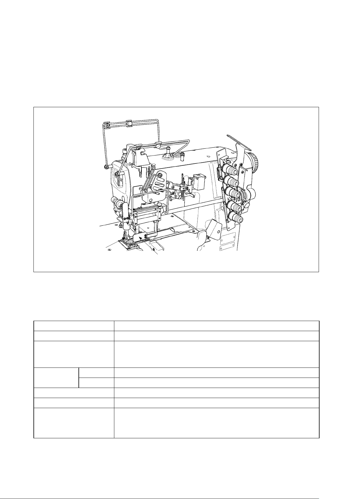
1. MD11 (TAPE FEED DEVICE)
This device is the device that is used for attaching elastic tape (elastic lace). This device supplies the ma-
chine with tapes of equal length, synchronizing the feed, and provides the sewing products of a ne nish.
Elastic tape (elastic lace) up to max. 45 mm in width can be used, and be supplied within the range of 0.9
to 3.5 mm per stitch.
2. SAFETY DEVICE
B
A
Eye protection cover : Cover to protect eyes from being injured by needle breakage
A
Finger guard : Cover to protect ngers from coming in contact with needles
B
3. SPECIFICATIONS
Model MD11
Class name Mechanical metering device
Sewing speed
3-needle 5.6 mm, 6.4 mm
Needle gauge
2-needle 4.0 mm
Tape width 45 mm
Tape feed amount 0.9 to 3.5 mm
Noise
Max. 5,000 sti/min (at the time of intermittent operation)
Speed of stitch at the delivery. 4,000 sti/min (at the time of intermittent operation)
-
Equivalent continuous emission sound pressure level (LpA) at the workstation :
A-weighted value of 76.5 dB; (Includes KpA = 2.5 dB); according to ISO
10821- C.6.2 -ISO 11204 GR2 at 4,000 sti/min.
– 1 –
Page 4

4. INSTALLING PROCEDURE OF THE ACCESSORIES
(1) Installing the pulley cover
Install pulley cover ❶ on the frame at three places
❶
❷
with screws ❷ with pulley cover ❶ opened.
After installing the pulley cover, conrm
that it does not interfere with other com-
ponents.
❶
❺
❺
❸
❹
❷
❷
❸
❶
❶
❹
❺
(2) Installing the support guide
1) Remove four screws ❶.
2) Attach studs ❹ to the place where screws ❶
have been removed.
3) Put support guide ❷ between washers ❺ and x
it to stud ❹ with screw ❶.
4) Fix support guide ❸ with the same procedure as
above 3).
(3) Installing the side guide
Attach two side guides ❶ respectively to two sup-
port guides which have been attached in step
Installing the support guide" p.2
.
"4-(2)
Fix the side guide on the left-hand side with screws
and the side guide on the right-hand side with
❷
thumbscrews ❸ respectively.
– 2 –
For adjusting the installing position
of the side guide width, refer to "6-(2)
Adjusting the side guide according to
the elastic tape width" p.4.
Page 5

5. LUBRICATING PROCEDURE
(1) Lubrication to the bearing
Grease has been applied to the bearing at the
•
time of delivery from the factory.
1) Remove screws ❶ and ❷ from the both ends of
the shaft and fully apply grease supplied as ac-
cessories.
2) After applying grease, attach screws ❶ and ❷ to
the both ends of the shaft.
❶
A
B
Left side face
❷
Right side face
(2) Lubrication to the clutch
• Grease has been applied to the clutch at the
time of delivery from the factory.
1) Remove the screw from section A of the clutch.
2) Apply grease supplied as accessories from sec-
tion A. At this time, apply grease until new grease
comes out from sections B.
3) After lling the grease, put the screw back in sec-
tion A and tighten it.
– 3 –
For the lubrication to the clutch, apply
grease at 100 hours of the operation as
a standard. There is the possibility that
excessive grease leaks from sections
of the clutch at the time of delivery or
B
of using after lubrication. When grease
leaks out, wipe it.
JUKI Part No. of exclusive grease :
13525506
Page 6

6. ADJUSTMENT OF THE ROUTE OF ELASTIC TAPE
❻
❶
❶
❶
(1) Supply route of the elastic tape
Pass elastic tape ❶ through the route after releas-
ing the follower roller.
(Refer to
LOCK" p.7
"9. FOLLOWER ROLLER RELEASE
.)
(2) Adjusting the side guide according to the
elastic tape width
Adjust the positions of side guides A ❶ at sections
A
(three places), side guide B ❷ at section B and
guide width ❺ of the presser at section B according
to the width of elastic tape to be used. For guide
width ❺ of the presser at section B, loosen screws
and ❹ and carry out adjustment.
❸
A
❶
B
❷
❼
❺
❸
❹
(3)
Removing /Attaching procedure of the presser
To remove or attach the presser, loosen presser
spring regulator ❻ and lower collar ❼.
(4) Adjusting the position of the tape guide
For the adjustment between tape guide ❶ and the
❷
presser, loosen screw ❸, and turn stopper ❷ to ad-
just. After the adjustment, x it with screw ❸.
❶
❸
– 4 –
Page 7

7. ADJUSTING PROCEDURE OF THE TAPE FEED AMOUNT
WARNING :
To protect against possible personal injury due to abrupt start of the machine, be sure to start the following work after turning the power off and ascertaining that the motor is at rest.
(1) Adjusting the feed amount with the thumbscrew
Tape feed amount can be adjusted by adjusting the
thumbscrew. Fine adjustment is performed in step
(2) Adjusting the spring pressure" p.5
amount can be adjusted within the range of 0.9 to 2.2
mm with this adjustment.
* When using the tape feed amount between 1.4 to
3.5 mm, refer to step (3).
1) Open pulley cover ❶, and loosen buttery nut ❷.
2) Turn knob ❸, and adjust the feed amount.
* Turn knob ❸ clockwise (+ direction) to in crease
the feed amount. Turn it counterclockwise (– di-
rection) to decrease the feed amount.
3) After tightening buttery nut ❷, close pulley cover ❶.
A : Increase
B : Decrease
❷
❶
❸
–
B
+
A
"7-
. Tape feed
A : Increase
B : Decrease
Fig. 1
(2) Adjusting the spring pressure
❶
❷
A
Fine adjustment of the feed amount can be performed
by adjusting the spring pressure.
1) Loosen nut ❶.
2)
Turn adjustment screw ❷ to adjust the spring pressure.
B
* When the spring pressure is increased, the tape
feed amount is decreased.
When the spring pressure is decreased, the tape
feed amount is increased.
3) Tighten nut ❶.
(3) Adjusting the feed amount with the cam
Tape feed amount can be changed from 0.9 to 2.2 mm
❷
❶
❶
(at the time of delivery from the factory) to the range of
1.4 to 3.5 mm by adjusting eccentric cam B ❶.
1) Remove the pulley cover and the pulley.
(Refer to Fig. 1.)
2) Loosen two screws in eccentric cam B ❶.
Fig. 2
3)
[When the tape feed amount is 0.9 to 2.2]
(Refer to Fig. 2.)
Tighten and x two screws in eccentric cam B ❶ at
❷
❶
the position where the notch of eccentric cam B ❶
comes in contact with the left-hand side of screw ❷.
[When the tape feed amount is 1.4 to 3.5]
(Refer to Fig. 3.)
Tighten and x the screw in eccentric cam B ❶ at the
Fig. 3
position where the notch of eccentric cam B ❶ comes
in contact with the right-hand side of screw ❷.
– 5 –
For the matters that demand special atten-
tion to the xed position of the eccentric
cam, refer to "8. INSTALLING POSITION
OF THE ECCENTRIC CAM" p.6.
Page 8

8. INSTALLING POSITION OF THE ECCENTRIC CAM
WARNING :
To protect against possible personal injury due to abrupt start of the machine, be sure to start the following work after turning the power off and ascertaining that the motor is at rest.
(2) Installing position of the eccentric cam
When performing adjustment of
the feed amount with the cam" p.5
Fig. 4
Fig. 3
❷
❶
of the points below for the installing position of ec-
centric cam B ❷.
1) Press eccentric cam B ❷ against screw ❶ of ec-
centric cam A as illustrated in Fig. 4.
2) Tighten two screws each ❼ and ❽ of eccentric
cams A ❶ and B ❷ so that clearances B and C
between washer ❺, pointer ❻ and rod ❸ are
equal in the state that buttery nut ❹ is tightened
as shown in Fig. 5.
"7-(3) Adjusting
, be careful
After the adjustment, turn the pulley by
hand to check that the cams move with-
out interference.
Fig. 5
❻
B
C
❺
❸
❹
– 6 –
Page 9

9. FOLLOWER ROLLER RELEASE LOCK
WARNING :
To protect against possible personal injury due to abrupt start of the machine, be sure to start the following work after turning the power off and ascertaining that the motor is at rest.
❷
❶
When operating the sewing machine with elastic
tape unused, the roller is maintained in the release
state by using the stopper.
1) Pressing the upper part of presser plate ❶ with n-
gers, turn stopper ❷ in the direction of the arrow.
2) When stopper ❷ is turned up to the position A,
roller ❸ is held at the release position.
A
❸
Release
– 7 –
Page 10

10. REMOVING THE TAPE GUIDE SECTION
WARNING :
To protect against possible personal injury due to abrupt start of the machine, be sure to start the following work after turning the power off and ascertaining that the motor is at rest.
❶
Remove mounting screw ❶. Then, the tape guide
section can be removed in the assembled state.
– 8 –
 Loading...