

Page 1
I.L^.
MODEL
HIGH
SINGLE
BUTTON-SEWING
MB-372
SPEED
THREAD
CHAINSTITCH
MACHINE
Instruction
Book
TOKYO
JUKI
INDUSTRIAL
CO..LTD.
Page 2
CONTENTS
1.
GENERAL
2.
SPECIFICATIONS
3.
NAMES
4.
CAUTIONS
5.
LUBRICATION
MOTOR
6.
NEEDLES
7.
8.
INSERTING
9.
THREADING
10.
THE
11.
FUNCTIONS
12.
THE
13.
ADJUSTING
14.
TO
PRODUCE
15.
POSITION
16.
TIMING
TENSION
17.
CHANGING
18.
STITCH
19.
HEIGHT
20.
ADJUSTING
21.
ADJUSTING
22. ADJUSTING
23.
CHANGING
ADJUSTING ITS HEIGHT
24.
CAUSES
25.
ATTACHMENTS
MACHINE
( i ) How to install the snap fastener attachment 22
(ii)
(iii)
{iv)
DESCRIPTION
OF
PARTS
PULLEY
THREAD
THREAD
THE
BEFORE
THE
THE
TENSION
OF
NIPPER
THE
OPTIMAL
OF
THE
NIPPER
DISC
THE
OPERATION
AND
BELT
NEEDLE
MACHINE
THE
THREAD
PULL-OFF
LEVER
NEEDLE BAR 10
STITCHING
NEEDLE
RELEASING
NO.
2 14
POSITION
GUARD
OF
PLUNGER
THE
CONDITION
BUTTON
OF
TRAY
SELECTING
OF
BUTTON
THE
THE
FOR
THE
OF
MALFUNCTIONS
TO
CLAMP
BUTTON CLAMP PRESSURE
BUTTON CLAMP STOP LEVER 18
2-HOLES AND 4-HOLES 18
BUTTON
MB-372
HOLDING
AND
BUTTON
CLAMP
REPAIRING
ATTACHING
AND
How to install the wrapped-around button clamp attachment 23
How to insall
How to
install
the
the
shank
button clamp attachment 25
metal
shank
button clamp attachment
•••
-15
•••
Page
1
2
3
4
4
5
6
6
7
8
8
9
12
14
15
17
17
19
21
21
27
Page 3
1.
GENERAL
DESCRIPTION
JUKI
machine.
as well as snap fasteners, shank
Model
It
MB-372
is widely used to
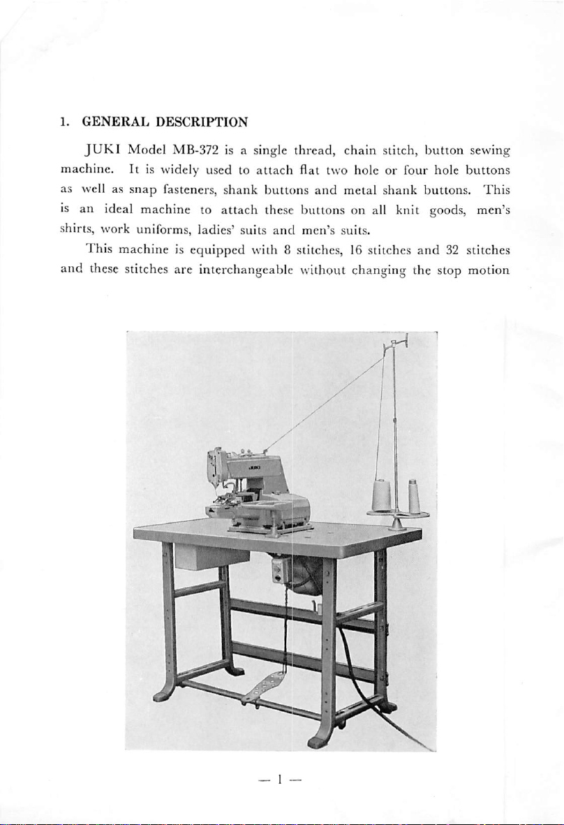
is a single thread, chain stitch, button sewing
attach
flat two hole or four hole
buttons
and
metal shank buttons.
is an ideal machine to attach these buttons on all knit
shirts, work uniforms, ladies' suits
This machine is equipped with 8 stitches, 16 stitches
and
these
stitches are interchangeable without changing the stop motion
and
men's suits.
goods,
and
buttons
This
men's
32 stitches
Page 4
cams. A speed slowing device, an exclusive
incorporated into this machine
and
consequently loosening of screws or
JUKI
attachment, is
malalignment of stitches which sometimes characterize a machine with
a stop motion mechanism is completely eliminated and assures a safe
and
stable stitching condition.
2.
SPECIFICATIONS
Model
Sewing type
Sewing fabric
Sewing speed
Button-sewiniar
Needle
Needle
Stitch
Feed
Button
Presser
Button
Thread
bar
number
length
size
bar
clamp
nipper
Stop motion
Lubrication
Power
required
Lubricating
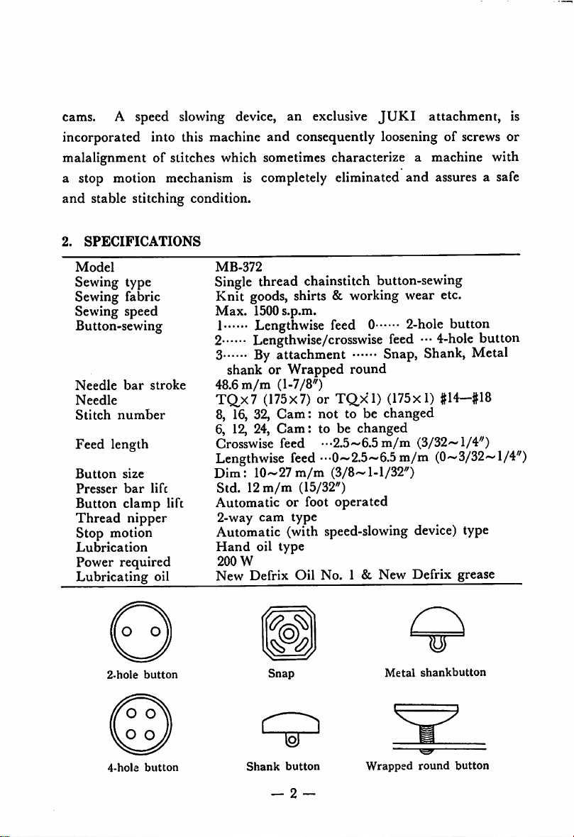
2.hole
button
stroke
life
lift
oil
MB-372
Single
thread chainstitch button-sewing
Knit goods, shirts & working wear etc.
Max.
1500s.p.m.
1 Lengthwise feed 0 2-hole button
2 Lengthwise/crosswise feed
•••
4-hole
button
3 By attachment Snap, Shank, Metal
shank or
48.6
m/m
TQx7
8,
16,
6, 12, 24,
Crosswise feed •••2.5~6.5
Lengthwise
Dim:
Std.12m/m
Automatic or foot operated
2-way
Wrapped
(1-7/8")
(175x7) or
32,
Gam:
Cam:
feed
10-27
m/m
cam
type
round
TQxl)
(175x1) #14-#18
not to be changed
to be
changed
m/m
(3/32~l/4")
••-0^2.5^6.5m/m (0~3/32~l/4")
(3/8-1-1/32")
(15/32")
Automatic (with speed-slowing device) type
Hand
oil
type
200
W
New
Defrix
Oil
No.
1 &
New
Defrix
grease
W
Metal
Snap
sbankbutton
4-hola
button
Shank
button
Wrapped
round
button
Page 5
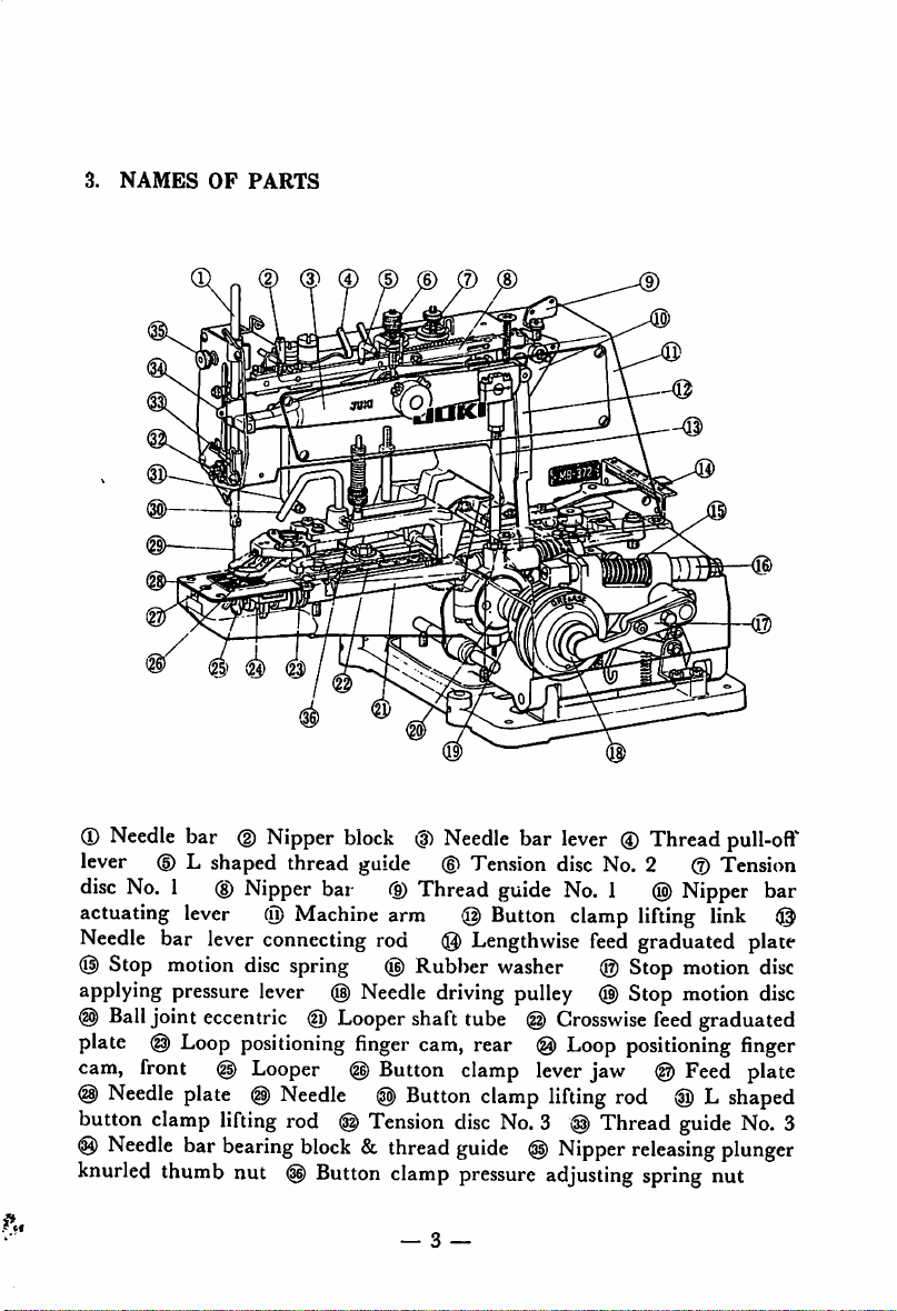
3.
NAMES
m
OF
PARTS
®
Needle
lever
disc
actuating lever @ Machine arm @ Button clamp lifting link
Needle
(!|)
Stop
applying pressure lever @
@>
Ball
plate @ Loop
cam, front @ Looper @ Button clamp lever jaw @ Feed plate
@
Needle
button
@
Needle
knurled
bar
(§)
Nipper
(D
L shaped thread guide ® Tension disc No. 2 0 Tension
No.
1
(D
Nipper
bar lever connecting rod
motion
joint eccentric @ Loopershaft tube
disc
positioning
plate
clamp
bar
thumb
@)
lifting
bearing
nut
block
bar 0 Thread
spring
(g)
Needle
finger
Needle
rod @
block
(g)
& thread
Button
@)
Tension
clamp
(|i)
Needle
(Q)
Rubber washer ® Stop motion
driving pulley @ Stop motion disc
cam,
Button
— 3 —
bar
guide
Lengthwise
(§)
rear @
clamp
disc
No.
guide
@
pressure
lever
® Thread
No.
1 @
feed
graduated plate
Crosswise
Loop
lifting
feed
positioning
rod
3 @ Thread
Nipper
adjusting
releasing
spring
pull-oft^
Nipper
bar
disc
graduated
finger
(0)Lshaped
guide
No.
plunger
nut
3
Page 6
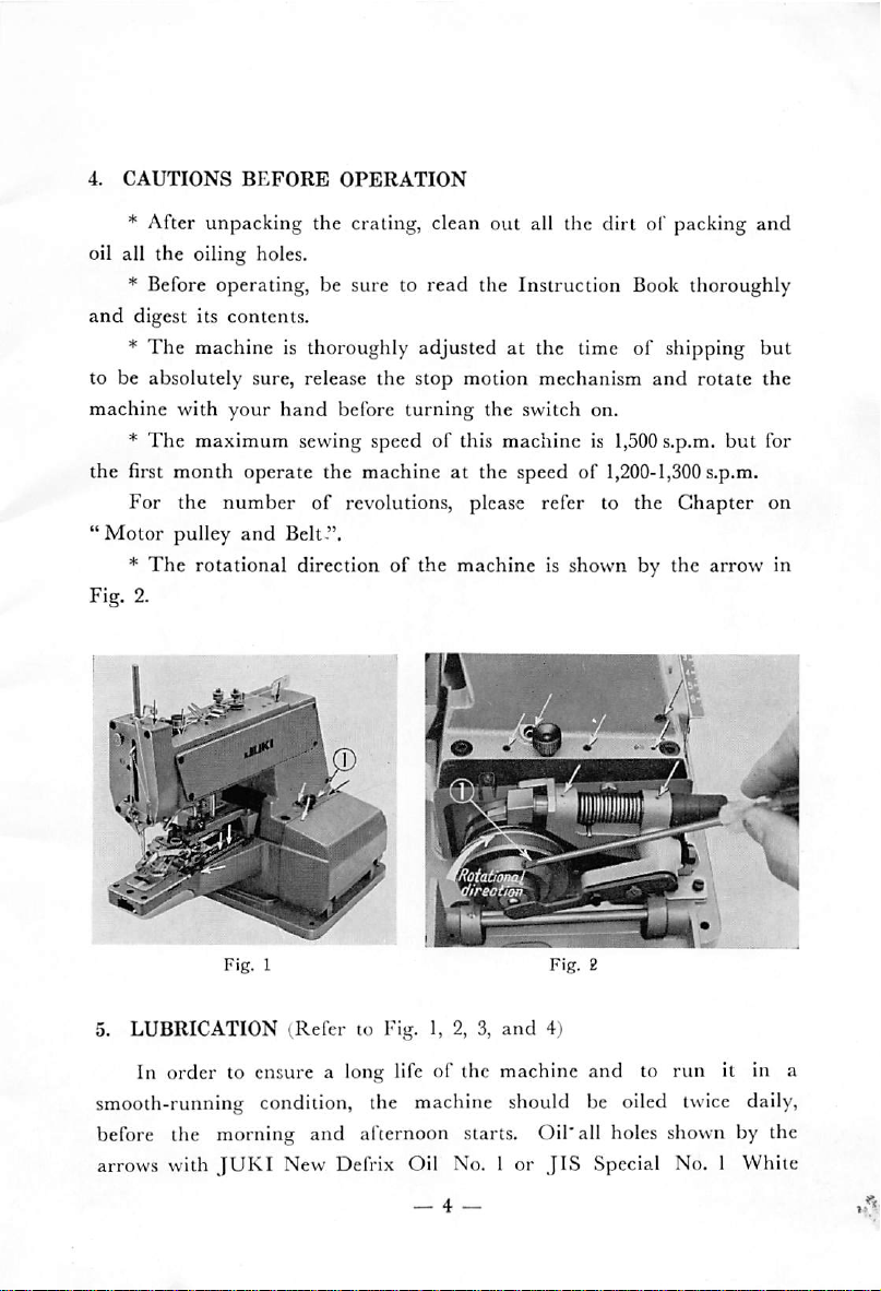
4.
CAUTIONS
BEFORE
OPERATION
* After unpacking the crating, clean out all the dirt of packing
oil all the oiling holes.
* Before operating, be sure to
and
digest its
*
The
to be absolutely sure, release
machine with your
*
The
contents.
machine is thoroughly adjusted at the time of shipping but
hand
before
maximum
sewing speedofthis
the first month operate the machine at the speed of
For
the
"Motor
*
number
pulley
The
It
and
rotational direction of
of
revolutions, please refer to the
Belt".
the
read
the Instruction Book thoroughly
stop
motion
turning
the
machine is shown by the
mechanism
the switch on.
machine
is 1,500s.p.m.
1,200-1,300
and
Chapter
rotate
but
s.p.m.
arrow
and
the
for
on
in
oia
'ireotiM
5. LUBRICATION
In order to ensure a long life of the machine
(Refer
to Fig. 1, 2, 3,
and
4)
and
to run it in a
smooth-running condition, the machine should be oiled twice daily,
before the morning
arrows with
JUKI
and
afternoon starts. Oil*all holes shown by the
New Defrix Oil No. I or
— 4 —
JIS
Special No. 1 White
Page 7
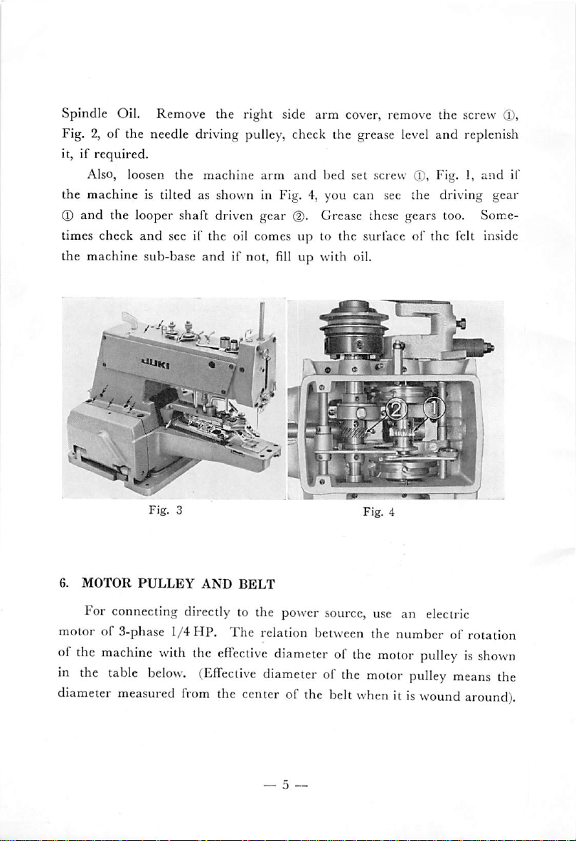
Spindle Oil. Remove the right side arm cover, remove the screw d),
Fig. 2, of the needle driving pulley, check the grease level and replenish
it, if required.
Also, loosen the machine
the
machine is tilted as shown in Fig. 4, you can sec the driving
(T)
and
the looper shaft driven
and
times check
the machine sub-base and if not, fill up with oil.
see if the oil comes up to the surface of the felt inside
arm
gear
and
bed set screw ®, Fig. 1,
(2).
Grease these gears too. Some
and
gear
=
il"
6.
MOTOR
For connecting directly to the power source, use an electric
motor of 3-phase 1/4
of the
in the
diameter
PULLEY
machine
table
measured
with
below.
AND
HP.
the
(Effective
from
BELT
The
relation between the
effective
diameterofthe
the
centerofthe
diameter
— 5 —
of the
belt
numberofrotation
motor
motor
whenitis
pulleyisshown
pulley
wound
means
around).
the
Page 8
Cycles
Rotation
Part
motor
No.
pulley
of
Effective
motor
diamater
pulley
of
1,500
50
r.p.m.
1,200r.p.m.
1,500r.p.m.
7.
60
NEEDLES
1,300
r.p.m.
At the time of shipping, the needle No.
to the machine
needle is shorther
but
needle No.
than
B710137200H
B710237200H
B710237200H
B710337200H
TQx7,
70
m/m(23/4")
58.2
m/m(21/4")
58.2
m/m
(21/4")
50.3
m/m(115/is")
TQx7
TQx
1 (175x1) can also be used.
(175x7) is attached
TQx
so when attaching buttons, take in the
height of the button, thickness of the sewing material into consideration
and
when the needle comes down to the lowest point, be careful to see
that
the
shank
of
the
needle
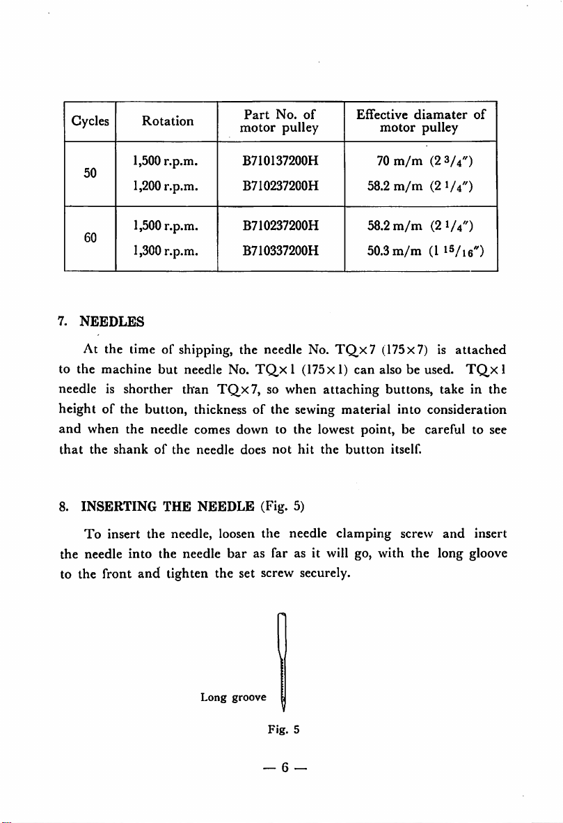
8.
INSERTING
To
insert the needle, loosen
THE
NEEDLE
the needle into the needle
does
not
hit
the
button
itself.
(Fig. 5)
the
needle
bar
as far as it will go, with the long gloove
clamping
screw
and
insert
to the front and tighten the set screw securely.
1
Long
groove
V
Fig.
5
— 6 —
Page 9

To
thread
motion
the
thread
No. I
No. 2
position,
diagram
spool
♦
(g)—»
thread guide No. 2
plate—»thread guide No. 3
ing block
disc No. 3
» to
the
and
draw
1/4").
the machine,
and
threadinaccordance
as shown in Fig. 6, 7.
stand—»
tension disc No. I
needle
put
thread
d)—»
it in stop
Start
guide pin
tension disc
thread puIl-ofTlever »nipper
(6)—♦
upper eyelet of (ace
(2)—*
and
thread
thread
needle eye from front
the
thread
guide
out
guide
(9)-^
about
needle
(§)—*
tension disc No. 3
6-^7
bar
thread
toward
m/m
with
from
(§)—•
bear
tension
rear
(about
To draw out the thread, push the nipper
releasing plunger knurled nut, @ the nipper will
be
released
and
the
thread
can
be
drawn
out.
ThreadX
int
u
IJ
Page 10
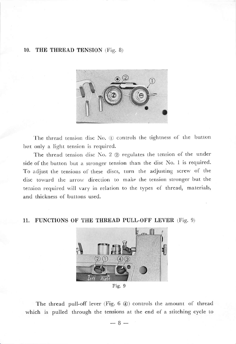
10.
THE
THREAD
TENSION
(Fig. 8)
The thread tension disc No.
Ci)
controls the tightness of the button
but only a light tension is required.
The
thread tension disc No. 2(Dregulates the tension of the under
sideofthe button but a stronger
To adjust the
disc toward the arrow direction to make the tension stronger
tensionsofthese
tension
discs,
than the
disc
No.
turn the adjusting screw of the
1 is required.
but
the
tension required will vary in relation to the types of thread, materials,
and
thickness
11.
FUNCTIONS
The
of
buttons
OF
THE
used.
THREAD
@0)
PULL-OFF
LEVER
(Fig. 9)
thread pull-off lever (Fig. 6 ®) controls the amount of thread
which is pulled through the tensions at the end of a stitching cycle to
Page 11

provide sufficient thread for the first stitch of the following cycle.
should be adjusted according to the size
fiat
button,
This
rear
side front cover
shank
adjustmentismade
block
(D
button,
by inserting a screw driver through the hole of the left
and
etc.
by loosening screw ®
move the block to
right, the sagging of the thread is increased
the sagging decreases.
When,atthe
end
of a sewing cycle,ifthe tail of the
through the button hole (Fig. 10 arrow A), move it to left
appears toward the arrow B (Fig.
tail
of
the
thread
will
not
come
10),
out.
and
kinds of buttons such as
of
the
right
and
left.
If
it's moved to
and
if it's moved to left,
thread
but
move it toward right so
nipper
appears
if the tail
that
It
bar
the
12. THE THREAD
o
NIPPER
oo.
(Fig. 11)
•i®]
0.8-1.2%
nipper
B
Fig.
The
function of the thread
o'
o
o.
10
drawing out when, at the conclusion of a sewing cycle, the button clamp
ing device goes up and cuts the thread.
hold
the
thread
until
it's
cut.
However, during the sewing operation, adjust the nipper so
will not hold the thread. As shown in Fig.
loosening the nipper bar block set screw(DFig. 9, so that during the
running, the clearance between the nipper block and the nipper becomes
— 9 ~
.
'a:6
J
is to prevent the
The
nipper will pinch
11,
make this adjustment by
thread
from
and
that
it
Page 12

0.8~1.2m/m (about
and
lefttoattain
this
3/64")
clearance.
and by
moving
the nipper bar
block
to right
13. ADJUSTING
There are two timing lines at the top of the needle
liming lines at the bottom, a total of 4 timing lines
adjusting the height of the
lines when using short needles (TQ,Xl); for using long needles (TQ,x7)
use the lower
Step on the pedal
THE
NEEDLE
Fig.
12
pairoftiming
fully
BAR
(Fig. 12, 13)
Fig.
13
bar
and
two
(Fig.
12).
For
needle
lines.
bar,
use
the upper pair of timing
to release the stop motion trip lever and in
that position rotate the motor pulley toward the operating direction
with your right hand
lowest
A),
position,
depending
upon
(Fig.2)and when the needle bar has reached the
the upper line of the each pair of liming
the
lengthofneedle
used,
shouldbeeven
lines
(Fig.
with the
14
Page 13

lower edge of the needle bar bushing
If it's not
guide cjamp
tion and
the needle bar lower bushing.
make
even,
loosen
screw®(Fig.
the upper
the needle bar bearing block and thread
13)
when the
timing
At this point, bear in mind the
(i)
When the needle
screw (Fig. 13 ®) goes into the slot of the needle bar lower bushing.
(ii) Lightly tighten the needle
screw,
and
slot (Fig. 7)
(iii)
and
after installing the face plate,
thread
Timing
As per Chapter
guide comes to the center of the machine
and
the needle
bar
has risen, be sure that the needle clamping
bar
then tighten the set screw.
and
the looper
13,
the upper liming line of the pair of timing lines
(T).
line
even
following
Fig.
14
bearing block
needle
bar is at its
with the
lower
important points:
and
adjustsothat
lowest
posi
timing line of
thread guide clamp
the
bearing block
arm
front cover
became even with the lower edge of the needle bar lower bushing at the
lowest point of the needle bar, so rotate the pulley toward the operating
direction and adjust so that the lower timing line comes even with the
needle bar lower bushing. At this position, (Fig.14B) match the point
of the looper (Fig. 15 @) with the center of the needle
and
the
point
at
clearance between the needle
tighten the looper set screw (Fig. 15
(D)
securely.
0.05—0.1
and
m/m
make the
and
then
Page 14

Fig.
16
14. TO
is by a
timing of the
cam (front). The latter should be applied when disassembling the
machine and
adjusting the
There
simple
PRODUCE
arc two methods to produce an ideal slilching condition: one
OPTIMAL
STITCHING
CONDITION
{Vig. 15, 16)
adjustment of the looper and the other is to match the
looper
for
looper,
positioning
finger
with the
any other purposes, do not
refer
to the chapter on "Timing
loop
positioning
move
the machine. For
the
needle
finger
and
Page 15

the
looper"
(i)
Adjusting the
(Chapter 13 (iii)).
loop
positioning finger lever (Fig.
15,
16)
Release the stop motion and rotate the machine toward the operat
ing direction twice. (To release the stop motion, the machine must be
rotated
cam
more
than
twice).
At the lowest position of the needle bar, loosen the screw
and
looper sleeve(Dby locking from under the bed, slide the cam
(g)
of the
and looper sleeve toward the front and create a clearance with the loop
positioning finger cam (rear). To prevent the machine from moving
during the adjustment, lightly tighten one side of the cam and looper
sleeve screw
rotate
position of the loop positioning finger (Fig. 16 ®), make a clearance of
0.5~1.0m/m between the needle and the loop positioning finger edge as
showninFig.
(ii) Timing the loop positioning finger cam {front) (Fig. 15)
In
carved line of the loop positioning finger cam (rear) (I) with the cam
and
looper sleeve
(g).
Loosen the loop positioning finger
the
loop positioning finger
16.
order
to time the loop positioning finger
(D
carved line
cam
(rear) screw
cam
and
at
the
fartherest
cam
(front), match the
and
also with the carved line of the
(S),
advanced
loop positioning finger cam (front) © all on a straight line and then
tighten screws(D@. At this position, contact the
and looper
tighten
the
sleeve
(§)
set screw.
with the loop positioning
rear
end
finger
cam (rear) ®, then
of the
cam
(iii)
Verification
cams
offront and rear
Make sure that the height of the
at the
machine)
the needle
this height is
position
where
it
is within 55-^58mm
bar
upper bushing to the upper point of the needle bar.
less
than this, it might invite needle breakage.
positions
loop
beginstomove
(2-5/64"--2-1/4")
—13—
of the
loop
positioning
from
right to left
from
positioning
finger
finger
(Fig.16(D)
(facing
the
the upper point of
If
Page 16

15.
POSITION
OF
THE
NEEDLE
GUARD
(Fig. 16)
Adjustment should be made so
that
when the needle
barisat
the
lowest position, the clearance between the needle and the needle guard
@ comes to 0.05~0.1 mm by looseming the screw
guard
(g) to
rightorleft.
16.
TIMING
THE
NIPPER
RELEASING
DISC NO. 2 (Fig. 17)
Screw
Fig.
17
(Note:
The
This
is a very delicate technical adjustment, so be extremely
careful)
standard
motion is, as shown in Fig. 17, to
driving pulley toward the arrow direction as you pull the thread
the tension disc No. 2 will float up
and
quickly.
At this instant, the
height
to the top edge of the needle bar is
When
defective signs, as shown below, occur too frequently, try the
following
17, loosen
Insert
adjustments:
a screw
nut(Dand
driver
rotate the tension post toward the arrow direction.
from the needle
54'>'57
into
the
tension
(u)
and moving the needle
PLUNGER
Driver
OF
rotate
TENSION
the needle
the thread will be slipped
bar
upper
bushing surface
m/m (2-7/64'-2-3/16").
post
No. 2, as
shown
and
out
in Fig.
—
14
—
Page 17

When
this nut is tightened, the distance
bushing surface and the top edge of the needle bar becomes
standard distance and if this
direction of the arrow, this distance will become greater than standard.
tension
between
post is rotated in the
the
needle
bar upper
less
than
opposite
Defective
(i)
When
of
fabric
(ii)
When
instant
(iii) Too frequent thread breakage
17.
CHANGING
Normally, the button tray is attached to the right side of the
machine.
of
operation,
into the
18. STITCH SELECTING
But if
hole
signs
thread
tighteningofback
bad
the
th'-eadatstop
breaks
enroute
THE
this
loosen
the
which
I
Rotate
motion^t^pposite
Rotate
arrow
POSITION
OF
BUTTON
positionisinconvenient
button
is on the
{Vig.
left
tray
18)
side
leg
of the
set
Adjustment
tension
direction
tension
direction.
TRAY
depending
screw
front
post
no.2in
post
no. 2
upon
and
insert
part of the
toward
the
the
thenature
the
tray
table.
To
select
the
numberofstitches,
the
selectionbymeansofthe
latch
adjusting
screw©and
Fig.
stop
the
18
first
open
motion
cam
tightening
the
left
side
knob®,stitch
screw
©.
cover
do
selecting
Page 18

The
illustration which shows the selectionofstitches with the speed
slowing device in a released condition is shown in the figure, hut the
selection
( i ) S-s/i7c^ selecting (Fig. 19, 20)
cam knob
position
shown by ® Fig.
and
(ii)
car
The
Figure
This
8-stitch selecting
(D
.shown
becomes
16-slitch
be
made
without
20 shows the 8-stitch selecting.
toward the operator (Fig.
releasing the speed slowing device.
canbearranged
by pulling the stop motion
19)
and if this is moved to the
by the direction of the arrow, and set at the position
20,
an
8-stitch
selecting
Fig.
the stop motion cam
selection.
19
(T)
will stop half revolution
Fig.
20
With
the
8-slilch selected position, move the stop
(2).
The
stop motion
rotate
stitch
(iii) 32-stitch selecting (Fig. 20)
stitch selecting lever (D
one complete revolution at one sewing cycle
selecting.
With
the
16-stitch selected position, loosen screw
cam
with
the stitch selecting lever roll
0,
at the position shown in Fig. 19, will
your
hand
and
(J)
has gone up as shown in the Fig. 20, it
and
tighten
motion
cam
becomes a 16-
(a),
push down
screw
0.
knob
the
When
will push up the lever and with this action it will hold up the stop
motion
rotations)
tripping
and
lever ®. Thus, the cam will revolve once more (2
becomesa32-stitch
selecting.
Page 19

4'^5'ym
® ©
Fig.
21
If
the 32 stitch selecting cannot be obtained even, after all above
manipulations,
(D
toward
loosen
the
clamping
screw
rotate the adjusting
the arrow direction and re-tighten the clamp
screw
screw
(3).
19. HEIGHT OF
The
standard
clamp
foot
motion position is 12
the set
screw
BUTTON
distance
(D
and the upper
m/m
(g)
of the button clamp lifting rod and
CLAMP (Fig. 21)
between
the
surface
bottom
of the
(15/32"). To adjust to this distance, loosen
surface
feed
of
plate @ at the stop
move
it up or
the
20. ADJUSTING THE BUTTON CLAMP PRESSURE (Fig.
To adjust the button clamp pressure, rotate the button clamp pres
sure adjusting spring
surface of the button clamp pressure adjusting spring
screwed top
comestoabout
part
4~5m/m
nut
(Dsothat
the clearance between the
nut®and
of the button clamp pressure adjusting screw stud ®
(5/32*'-^3/16").
—
17
—
button
down.
21)
bottom
the
Page 20

21.
ADJUSTING
THE
BUTTON
CLAMP
Fig.
22
STOP
LEVER
(Fig. 22)
With the machine at stop motion
stop
lever
set
screw
(T)
and as the button
closebythe
showninFig.22and
or taken out, tighten the clamp screw
22.
ADJUSTING
First,
inches).
holes at the corners of the 4-hole square, match one side as the length
wise scale
(i)
Lengthwise scale (Fig. 23)
By
actionofbutton
measure
In the
pushing
and
case
the
down
after
FOR
2-HOLES
the distance
of 4 button
otherasthe
the
handle
clamp
makingiteasy
position,
clamp
lever
(2),
for
(1).
AND
4-HOLES
between
holes,
crosswise scale.
and indicator
the button
as all standard button
loosen
foot
set
the
the
buttontobe
spring
the button clamp
will
either open or
button
correctly
inserted
holes
(in mm or
holes
have
(Fig.23(D),
the indicator at the arrow position (0 position) for 2 holes and for 4
holes set it to the previously measured scale.
—
18
—
as
set
Page 21

Fig.
23
(ii)
Crosswise
After the lengthwise scale is set, next, set the crosswise scale. Loosen
the
crosswise
indicatortothe
releasing
the
needle
needle falls
center of the hole, loosen the nut
indicator,
fall in
the
the
stop
driving
tighten
center
scale (Fig.
feed
previously
motion
right
in
the
of
24)
indicator pin nut
measured
pulley
the
nut
the
hole.
plunger
(2)
from
toward
centerofeach
andbyrotating
(Fig.24(D),
position,
the
the operating
hole.
(g)
again, move the
stop
Fig.
tighten
motion
If
the
pulley,
21
set the
the nut
disc
direction,
it does
make
crosswise
and rotating
verify
not
crosswise
(2),
and
fall in
the
needle
feed
by
if the
the
feed
23. CHANGING
ITS HEIGHT (Fig. 25,
With
the
attachment
the
pedal,
the
the engaging button clamp lifting link lever hinge
hole d) in its front
Thenifthe
installed
button
pedal,
holding
systemistobeemployed,
Model
is to
clamp
S-shaped
clamp
THE
BUTTON HOLDING CLAMP AND ADJUSTING
26)
MB-372
be
usedorwhen
holding
and
is
hung
will
tighten the screw.
Machine,
the
deviceisattached.
chain
hook,
on the
button
movebythe
please
order
—
19
—
when
clampingofbuttonsisdone
whichisconnectedtothe
clamp
actionofthe
the
pedal
the
For
screw
lifting
and
shank
this
link
pedal.
chain
button
purpose,
(T),
move
hole
When
separately.
clamp
by
loosen
it the
newly
d), the
pedal
Page 22

The
clamp holding range is measured by moving the button clamp
and
down
but
lifting lever stop up
when changing to automatic system
from pedal system, make absolutely certain that the button clamp lifting
lever stop
(J)
is pulled way up from the contacting surface of the machine
Fig.
25
When
convertingtoautomatic
open
this
space
wide
Fig.
26
—20—
system,
Page 23

24.
Nature
CAUSES
of
malfunctions
OF
MALFUNCTIONS
Reasons
AND
REPAIRING
Repairing
Thread
Thread
inadequate
First
stitching
comes
button
Thread
at
stop
breakage
tightening
thread
outontop
excessively
cutting
motion
bad
Loop
bad
Nipperisholding
thread
Needle
the
Inadequate
ing
Timingoftension
No.2bad
Tension
No.2bad
Needle
the
Button
bad
Inadequate
of
of
tension
Bad
disc
Needle
hole
Inadequate
of
button
Nipper
bad
Button
too
strong
positioning
does
centerofhole
not
motion
fall
loop position
of
tension
does
not
center
clamp
fall
of
hole
pressure
adjustment
lever
timingoftension
No.
2
hitting
the
rising
clamp
thread
clamp
range
holding
pressure
the
in
disc
disc
in
button
Quicken
timingofthe
Adjust
Adjust
lever
Adjust
of
Retard
tension
Adjust
disc
Adjust
ing
Adjust
pressure
Adjust
rear
Rotard
tension
thread
Reset
Make
jaw
from
Adjust
Adjust
pressure
the
lever
about
jaw
loop
No.
tension
the
the
lower
with
with
the
with
with
holder
right
the
disc
the
2
with
jaw
the
the
the
disc
needle
button
adjusting
right
and
positioner
bar
clamping
left
timing
2
button
clamping
bar
timing
adjust
fall
clamp
(15/32")
bar
clamp
nut
left
block
timing
of
clamp
block,
of
the
lever
block
loop
nipper
button
and
positioner
float
no.
tensionoftension
the
holder
button
nipper
float
and
12m/m
plate
nipper
button
21 —
Page 24

25.
ATTACHMENTS
TO
MB-372
BUTTON
ATTACHING
MACHINE
As shown In Fig. 27, by
button
clamp
components
in case of snap attaching, thread guide No. 3 ® (Fig.
kinds
of
buttons
can
be
changing
(T),
attached:
button
the various
clamp
work support plate or
attachments
29).
the following
such as
(Note: Please order corresponding attachments for different kinds
of
buttons)
(i)
Snap
fastener
(ii)
Wrapped-around
(iii)
Shank
(iv)
Metal
(i)
How to
First, remove the button clamp components
button clamp work support plate
fastener attachment. Then, after setting the cross-wise feed
length-wise feed at 4 m/m
supportplate®
button
shank
install
Fig.28in
button
snap
fastener
attachment
(g)
(5/32")
each, install the button clamp work
suchaway
(1)
Fig. 27, also the
and in their place, install the snap
and
the
for
the
needletofall
evenly
on the
four cornersof the square hole. Next, install the snap fastener clamp. Fig.
28(Dwhile it is holding the snap to the snap fastener clamp jaw lever
and
lower the needle
If
the needle does not fall correctly, loosen the hexagonal screws ©
and
the see
that
it falls into the
snap
hole correctly.
—22—
Page 25

and
correct it. Finally verify if the
support
plate (D
and
the
DH
shape
[Ih
shape of the button clamp work
at
the lower surface
of
the
snap
fastener clamp slide are in perfect unison or not. Next, exchange the
thread guide No. 3 ® to that of snap fastener as shown in Fig. 29.
The
thread guide No. 3 should be installed vertically.
Fig.
28
(ii)
How to install the wrapped-around button clamp (Fig. 30, 31, 32)
A.
Sewing
flow of
work
Fig.
29
In sewing in the wrapped-around button, there are 2 stages of work
flow:
around
the
so-called
" process.
"button attaching"
process
and the "wrapping
The button attaching process is a preliminary process before the
wrapping
around
process
and
the
distance
between
the
button
and
the
cloth is lengthened beforehand and the button is sewn on and finally
the warpped around process is done with the wrapped around attachment.
Page 26

B.
Installing
Fig.
the
rr
.
30
attachment
Fig.
31
a. Attaching the
button
attaching
attachment
(Fig. 30)
For the button attaching process, securely fix in the wrapped-around
button clamp snaking foot
wrapped around installing
to see that both button clamp jaw lever
(T)
to the button clamp jaw lever with the
screw(Dand guide pin screw
(2)
and
the clamp snaking foot
(§)•
Be
careful
(i) are placed equi-distant from the center of the button to the right
and
left
and
also
not
b.
Attaching
touch the
evenifthe
button
the
clamp
wrapped-around
needle
snaking foot
attachment
falls
(J).
into
the
button
hole,itwill
After the button attaching process is conpleted, remove the button
clamp component ® and button clamp work support plate(DFig.
and in the place of support plate
ment (Fig.31^).
This attachment should be adjusted by looseniug the
button necking attachment set screw Fig.
position
as the
central
pivot,
right and left should be all equi-distant.
the
(2),
install the wrapped-around attach
31
(g)
and with the needle fall
clearance
between
Also,
front
and rear and
the length of the wrap-
27,
Page 27

ping can be adjusted by the clearance between the button necking large
guide
(2),
Fig. 31
and
the small guide
(D,
Fig. 31.
C. Sewing process
a)
Howtoattach
buttons
When the button attaching attachment is installed, the sewing pro
cess can be done in the same manner as an ordinary flat button,
but
the distance from the button to the cloth is long, it is necessary to adjust
the thread adjusting lever beforehand to make the drawing
thread
longer.
outofthe
as
b) How to
Insert the button, which is already attached by the
wrap
the
button
button
attaching
process, into the position shown by the arrow (Fig. 31) by twisting it
somewhat as shown in Fig. 32.
The
graduation
should be so set
that
the
length-wise feed should be in the same position as in the case of 2-hole
buttons.
(iii) How to install
the
shank
button clamp attachment
A. Remove the button clamp component. Fig. 27 (i) and the button
clamp work support plate(Dand
(Fig. 33
fall in
(D).
Adjust the
the
middleofthe
button
needle groove
install the shank button clamp bracket
clamp bracket ® so
and
tighten
that
the needle will
the
screw d).
The shank button adapter ® is a part of a set with the button clamp
(§),
holder
shown in Fig. 34. Also, plug in the button clamp stud
(2)
of the
so install this adapter on the built-in button clamp position as
(g)
jaw
of the
arm
and
tighten the screw ©.
The button clamp block
(g)
should be fixed in such a position as to
into the hole
make it easier to handle depending on the size of the button or sewing
condition. Then, exchange the button holding clamp in accordance with
the method described in
Chapter
23.
—
25
—
Page 28

0.5-1.0
Fig.
34
B Adjusting the attachment
Make
sure
that
the needle grooveofthe
fits into the needle groove (D of the
If
it doesn't fit, then
screw
that
Rotate
it falls equi-distant, right
adjust
by loosening the
the pulley with
and
button
your
left, with the shankofthe shank
hand
adapter
clamp
and
(§)
Fig. 33 perfectly
work
support
button
clamp
drop the needle to see
plate
holder set
button
as the central pivot. When this is verified, tighten the button holder
set screw @. Also,
0.5-'1.0mm
surface
and
between
the
sewing cloth from pushing
left
make
the
end
sure
button
surface
out
that
thereisjust
clamp
of
the
the button.
—26—
work
adapter
sufficient
support
Then,
spaceofabout
plate
@ left
(8)
as to
prevent
tighten the screw
end
the
(§).
Page 29

Next,
loosen
shank button holding clamp © holds the exact center of the button.
To
adjust
®, loosen the thrust collar set screw ®, Fig. 35, and if the thrust collar
® Fig. 35 is rotated, the
an optimal pressure.
When you do
® Fig. 35 will not develop any rattling along the shaft direction.
G.
In order to attach the shank button
the
cross-wise
the
screw
® @ Fig.35 and makeadjustment so that the
the
holding
this,
feed as much as possible.
pressure
pressure
of the
of the spring will change, so set it at
be sure that the button clamp lever holding
shank
securely,
button
holding
try to minimize
clamp
To maintain a stable stitching condition, make doubly sure that the
needle is not contacting the needle
clamp work support plate, then start the button attaching task.
groove
of the adapter or the button
The holding pressure of the button holding clamp ® Fig. 35 should
be sufficiently strong enough so that the button does not move during
the stitching operation.
(iv)
How
to install the metal shank
A. To install the metal shank button clamp attachment, remove the
button clamp holder
Fig.
27
and, as
plate @ to the installing part of screw ©. At the same time, adjust the
(T)
and the button clamp
showninFig.
button
clamp
attachment
feed
plate(Das shownin
36,
attach the shank button clamp
(Fig.
36,
37)
feed
Fig.
35
—
27
Fig.
33
Page 30

Fig.
17
Fig.
37
38
@ so
shank button work support plate(Dand
that
the needle falls between the needle groove ©ofthe metal
then tighten the screw ©.
As the metal shank bvitton adapter ® is a part of the set of the
button clamp holder ©, attach it to the built-in clamp holder spot, as
showninFig.
B. To adjust this attachment,
to the footofthe
If
the metal shank
It
would be better at this time to raise up the right shoulder of the
button guard ®
shoulder.
Next, loosen the
that
the circular groove surface of the lower part of the adapter ®
37.
first,
insert the metal button to be attached
adapter
and
®.
button
guard
®, is too loose, tighten it, somewhat.
set the foot of the metal button solely by the left
button
clamp bracket set screw ©
and
adjust so
exactly meets the grooved surface of the work support plate ®.
After adjusting, drop the
right and left with the base of the metal button as the central pivot
when
this is verified,
be sure to
createadistance
tighten
needletosee
the
adapter
" a "
between
—
28
that
needle
falls
evenly
and
set
screw ®.
the
left
endofthe
—
And
here also,
work
sup-
to
Page 31

port plate
(§)
and the left end of the adapter ® just sufficient to prevent
the sewing cloth from pushing out the button, then tighten the set screw
Normally, this distance
C.
a) In
Cautions
ordertoattach
on sewing operation
"a"
is
l-'1.5m/m.
the metal shank buttons securely, try to make
the crosswise feed as little as possible.
b)
To
maintain
a stable stitching condition, be sure to verify
needle is not touching cither the adapter or the needle groove of
the work
support
plate
or the baseofthe metal
button.
that
the
Page 32

SUBCLASS
SINGLE
MACHINES
THREAD
INDUSTRIAL
OF
CHAIN
MODEL
STITCH
SEWING
MB-372
BUTTON
MACHINE
HIGH
SEWING
SPEED
SUBCLASS 1
Diameterofbutton
Distance
circumferenceofbuttons
Button
Button clamp lever
Button clamp lever jaw, left
Button clamp lever
Material
SUBCLASS
Diameterofbutton
Distance
FOR
between
clamp
lever
presser lower
2
FOR
between
SMALL
outer
jaw,
jaw
jaw
MEDIUM
outer
BUTTONS
10~20mm
(STANDARD
(3/8"~25/32")
Under
right
B-2555-372-000
holding spring right
B-2557-372-000
holding spring, left B-2558-372-000
plate
SIZE
12~20mm
diameter
B-2529-372-000
BUTTONS
(15/32"--'25/32")
of
buttons
Material presser lower plate for medium size buttons
(Note) All
SUBCLASS
Diameter
Distance
3
other
FOR
of
button
between
specifications
LARGE
outer
circumserence
SIZE
15—25mm
are
same as SUBCLASS 1
BUTTONS
(9/16"
of
5-7.5mm
Button clamp lever jaw, right
for large size
buttons
for large size buttons holding spring D-2555-372-C00
Button clamp lever jaw, left,
for large size buttons D-2557-372-C00
for large size
buttons
holding
spring
Material presser lower pleat D-2529-372-C00
4.8mm
4~6mm
—31/32")
buttons
MACHINE)
(5/32")
B-2556-372-000
(5/32"-1/4")
D-2529-372-B00
(3/16"-9/32")
D-2555-372-C00
D-2558-372-C00
SUBCL.\SS
Numberofstitches
(Note) All
4
6, 12, 24
other
specifications are same as
other
subclasses
Page 33

CONVERSION
TABLE
1
mm
1.5mm
2
mm
2.5mm
3
mm
3.5mm
4
mm
4.5mm
5
mm
5.5mm
6
mm
6.5mm
7
mm
7.5mm
8
mm
8.5mm
9
mm
9.5mm
10
mm
11
mm
12
mm--
13
mm-
14
mm--
15
mm--
16
mm--
17
mm-
18
mm-
19
mm--
20
mm-
Milli
Meter
5/128"
1/16"
1/16"
3/32"
1/8'
1/8"
5/32"
5/32"
3/16"
7/32"
1/4"
1/4"
1/4"
9/32"
5/16"
5/16"
3/8"
3/8"
3/8"
7/16"
15/32"
33/64"
35/64"
9/16"
5/8"
43/64"
11/16"
3/4"
25/32"
to
less
plus
plus
less
plus
plus
plus
less
less
plus
plus
plus
plus
less
less
plus
less
plus
less
plus
plus
plus
less
plus
plus
Inch
1/256"
1/64"
1/256'
1/128'
3/256"
5/256"
1/128'
1/256"
1/64"
i/256"
3/128"
3/256"
5/256"
3/128"
1/256"
1/64"
1/128'
1/256"
1/256"
3/640"
3/128"
3/640"
1/256"
1/64"
3/128"
InchtoMilli
1"
1/2"
1/4"
3/4'
1/8"
3/8"
5/8"
7/8"
1/16"
3/16"
5/16"
7/16"
9/16"
11/16"
13/16"
15/16"
1/32"
1/64"
1/128"
Meter
25.4
12.7
6.35
19.05
3.175
9.525
15.875mm
22.225mm
1.5785mm
4.7625mm
7.9375mm
11.1125mm
14.2875mm
17.4625mm
20.6375mm
23.8125mm
0.79375mm
0
396875mm
0.19844mm
'
m|n
mm
mm
mm
mm
mm
 Loading...