

Page 1

MB-1800 Series
INSTRUCTION MANUAL
Page 2

CONTENTS
!. SPECIFICATIONS .............................................................................................1
@. NAME OF EACH COMPONENT ....................................................................... 2
1. Name of the main unit ....................................................................................................................... 2
#. INSTALLATION .................................................................................................3
$. PREPARATION OF THE SEWING MACHINE ..................................................7
1. Attaching the needle .........................................................................................................................7
2. Threading the machine ..................................................................................................................... 7
%. OPERATION OF THE SEWING MACHINE....................................................... 8
1. Names of the operation panel switches .......................................................................................... 8
2. Pattern table....................................................................................................................................... 9
3. Operating procedure of the operation panel (basic volume) ......................................................10
4. Stitching without the crossover thread ......................................................................................... 11
5. Operating procedure of the operation panel (applied volume) ................................................... 11
6. How to use the memory switch...................................................................................................... 13
^. ADJUSTMENT OF THE SEWING MACHINE ................................................. 14
1. Thread tension adjustment ............................................................................................................ 14
2. Adjustment of thread hauling amount .......................................................................................... 14
3. Timing of thread tension release ...................................................................................................14
4. Adjustment of the thread tension guide on the face plate ..........................................................15
5. Adjustment of needle-to-looper relation .......................................................................................15
6. Adjustment of the needle guide .....................................................................................................16
7. Adjustment of the thread trimming mechanism........................................................................... 16
8. Adjusting the height of the button clamp unit .............................................................................. 17
9. Adjusting the work pressing force ................................................................................................ 17
10. Adjustment of the button clamp stop lever .................................................................................. 17
11. How to adjust the position of the feed origin ............................................................................... 18
12. Installing the save button bar (accessory part) (MB-1800, MB-1800B) ......................................19
13. Adjusting the wiper (Optional for MB-1800) ................................................................................. 19
&. ATTACHMENTS ..............................................................................................20
1. Attachment for shank buttons (pearl buttons) (14617658, 14617757) ........................................ 21
2. Attachment for the first process of wrapped-around buttons (B24473720A0) ......................... 21
3. Attachment for the second process of wrapped-around buttons (MAZ046010A0) .................. 22
4. Attachment for snap (14617955) .................................................................................................... 22
5. Attachment for metal buttons (14618052) ..................................................................................... 23
*. ERROR LIST .................................................................................................... 24
(. TROUBLES AND CORRECTIVE MEASURES ............................................... 25
). OPTIONAL .......................................................................................................26
1. Installing the without-crossover-thread device (Part No. : M85126300A0)................................ 26
_. DRAWING OF THE TABLE ............................................................................. 27
Page 3

!. SPECIFICATIONS
1) Sewing area : X (lateral) direction 10 mm
Y (longitudinal) direction 6.5 mm (0.2 mm pitch)
2) Max. sewing speed : 1,800 sti/min
3) Feed motion of button clamp : Intermittent feed (2-shaft drive by stepping motor)
4) Needle bar stroke : 48.6 mm
5) Needle : TQx7, TQx1 (TQx7 #16 at the time of delivery)
6) Button size : 10 to 28 mm
7) Lift of button clamp : Standard 10 mm Max. 14 mm
8) Memory of pattern data : EEP-ROM (32K byte)
9) Enlargement/reduction system : Increase/decrease of stitch length system
10) Limitation of sewing speed : Sewing speed can be optionally limited to 400 to 1,800 sti/min
with the up/down key. (Adjustable in 100 sti/min unit)
11) Pattern selection function : 1 to 99 patterns can be specified by selecting the pattern Nos.
12) Memory back-up : In case of a power interruption, the pattern being used will be
automatically stored in memory.
13) Sewing machine motor : 100W servo motor (direct-drive)
14) Dimensions of machine head : W : 240 mm L : 550 mm H : 360 mm
15) Mass : 25 kg
16) Power consumption : 150 W
17) Operating temperature range : 5 to 35˚C
18) Operating humidity range : 35 to 85% (no dew condensation)
19) Line voltage : Rated voltage ± 10% 50/60 Hz
20) Noise : - Equivalent continuous emission sound pressure level (LpA) at
the workstation :A-weighted value of 79.5 dB; (Includes KpA =
2.5 dB); according to ISO 10821- C.6.3 -ISO 11204 GR2 at
1,800 sti/min.
* Reduce the max. sewing speed in accordance with the sewing conditions.
SPECIFICATIONS
1
Page 4
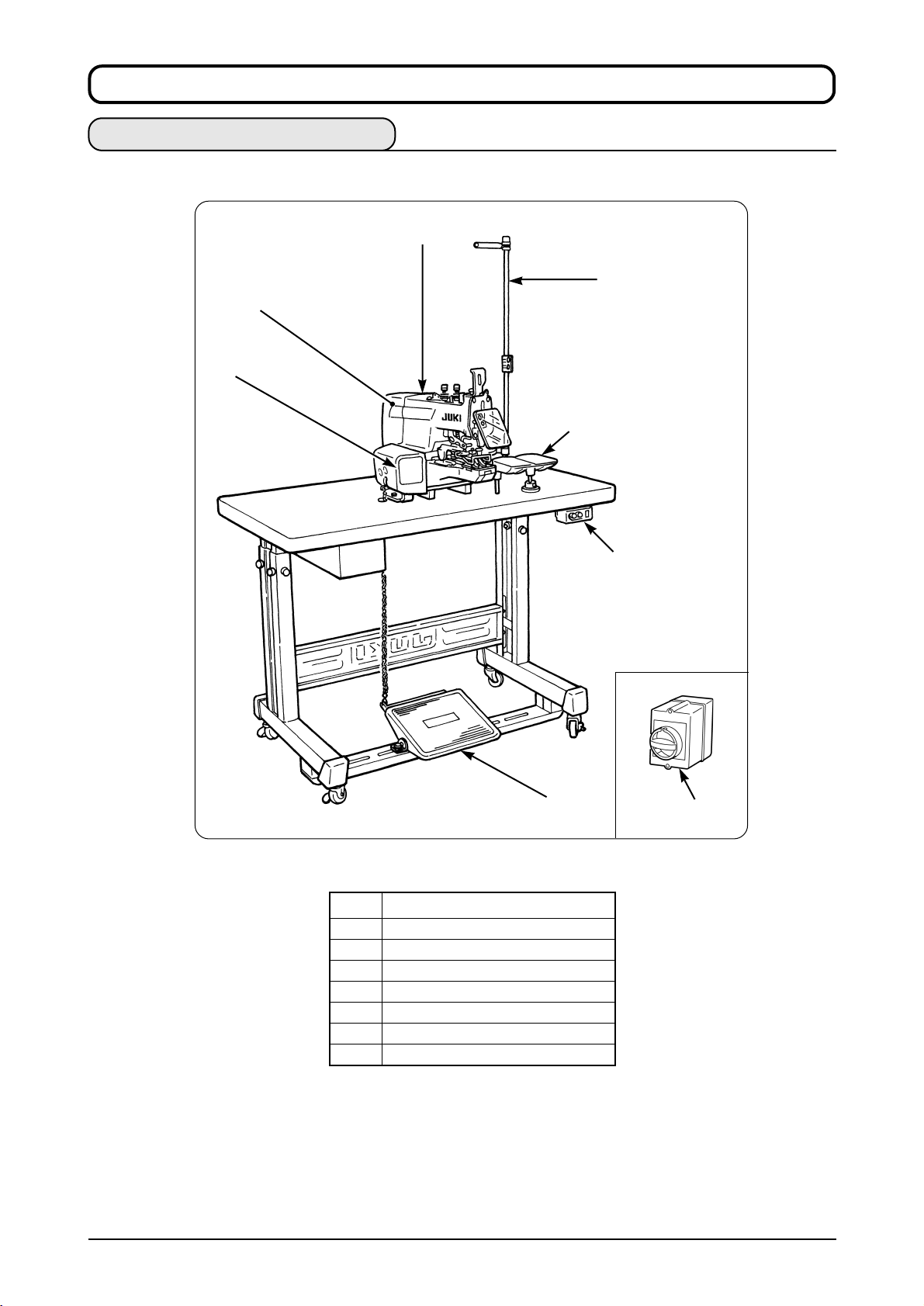
@. NAME OF EACH COMPONENT
1. Name of the main unit
1
2
3
4
5
6
8
7
The MB-1800 type machine consists of the sections listed in the following table.
1 Machine head
2 Electrical components
3 Operation panel switch
4 Thread stand
5 Button tray
6 Power switch
7 Power switch ( EU type)
8 Starting pedal
2
NAME OF EACH COMPONENT
Page 5
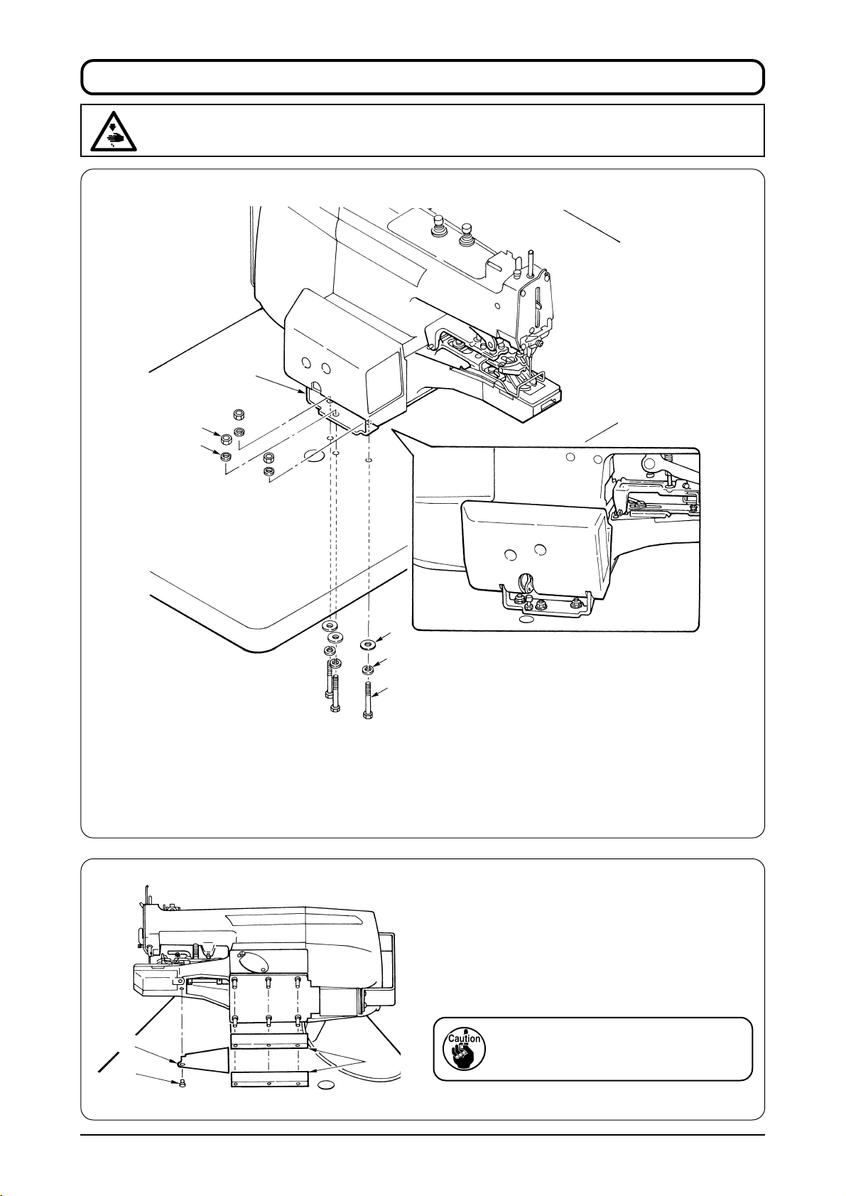
#. INSTALLATION
WARNING :
Be sure to perform the work with both hands when transporting the sewing machine.
(1) Installation of machine head
4
6
5
3
2
1
1) Place the machine head on the table and adjust the hole position of the table to the hole position
of bed installing base 4. Pass spring washer 2 , and large washer 3 to bolt 1 supplied with the
machine from the installing hole located at the bottom face of the table and set the bolt so that
it comes out from the hole of bed installing base 4.
2) Put small washer 5 and nut 6 in order and tighten bolt 1 and nut 6.
(2) Attaching the bed cover and the
rubber base
Tilt the machine head and fix bed cover 1 with
screw 2. Next, insert rubber bases 3 into the
pin protruding from the bottom face of the
machine bed.
When tilting/raising the sewing machine
1
3
2
head, hold the machine arm section by
hand and slowly tilt it until it stops.
INSTALLATION
3
Page 6
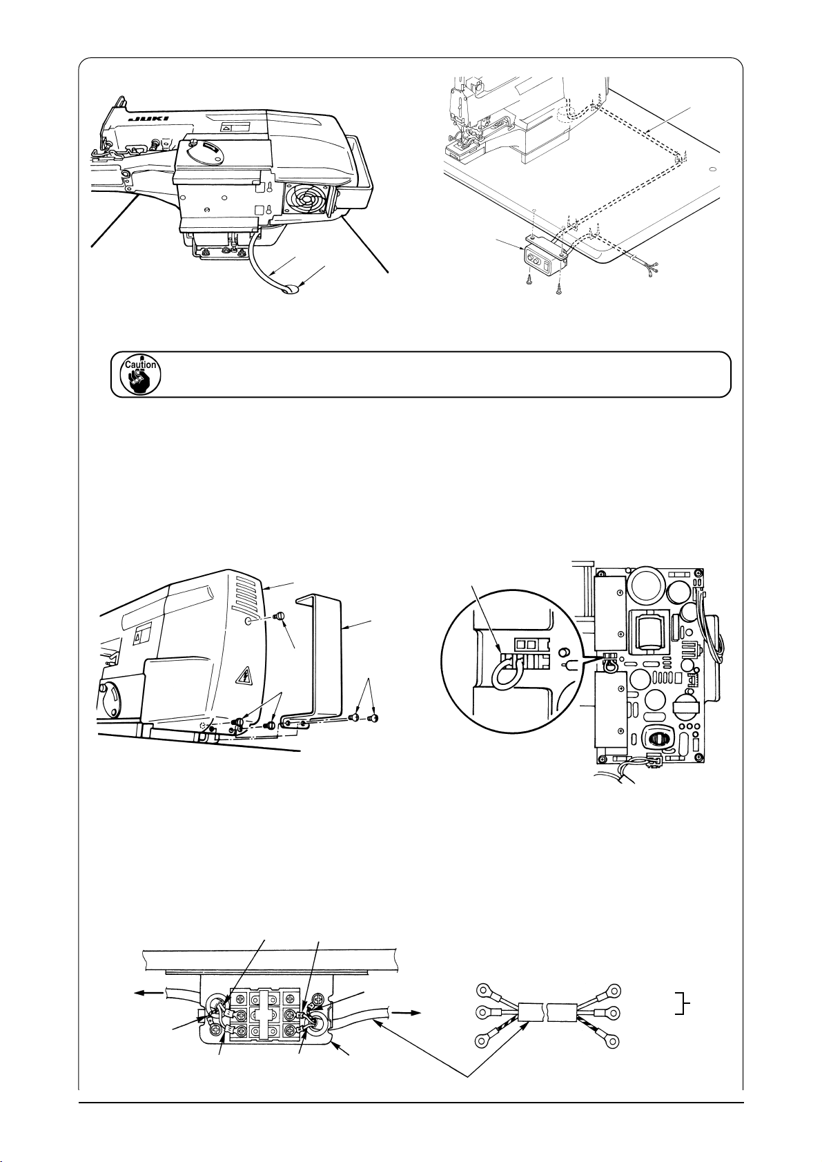
(3) Connection of power cord
1
2
1
A
1) Tilt the sewing machine and put out cord 1 coming out from the sewing machine to the lower
side from hole A in the table.
When tilting/raising the sewing machine head, hold the machine arm section by hand and slowly
tilt it until it stops.
2) Install power switch box 2 on the bottom face of the table and fix cord 1 on the bottom face of
the table with the staple supplied with the machine so that the cord can be connected to power
switch box 2.
3) When using the sewing machine with the single phase 100 to 120V.
(200 to 240V at the time of delivery)
It is necessary to change over the connector on the circuit board mounted on the sewing machine.
3
1
4
2
4
5
200V
100V
1 Remove electrical components cover guide 1 using setscrew 2.
(This cover is required only for transportation or the like. It is not necessary to install it again.)
Next, remove electrical component cover 3 using setscrew 4.
2 Change over connector 5 located on PWR circuit board to the side of 100V.
• Connection of single phase 100 to 120V
Sewing
machine
head
Green/yellow
4
INSTALLATION
Table
Light blue Light blue
Brown
Brown
Green/yellow
Power switch
Plug
Power cable
Brown
Light blue
Green/yellow – GND
AC 100V
to
AC 120V
Page 7
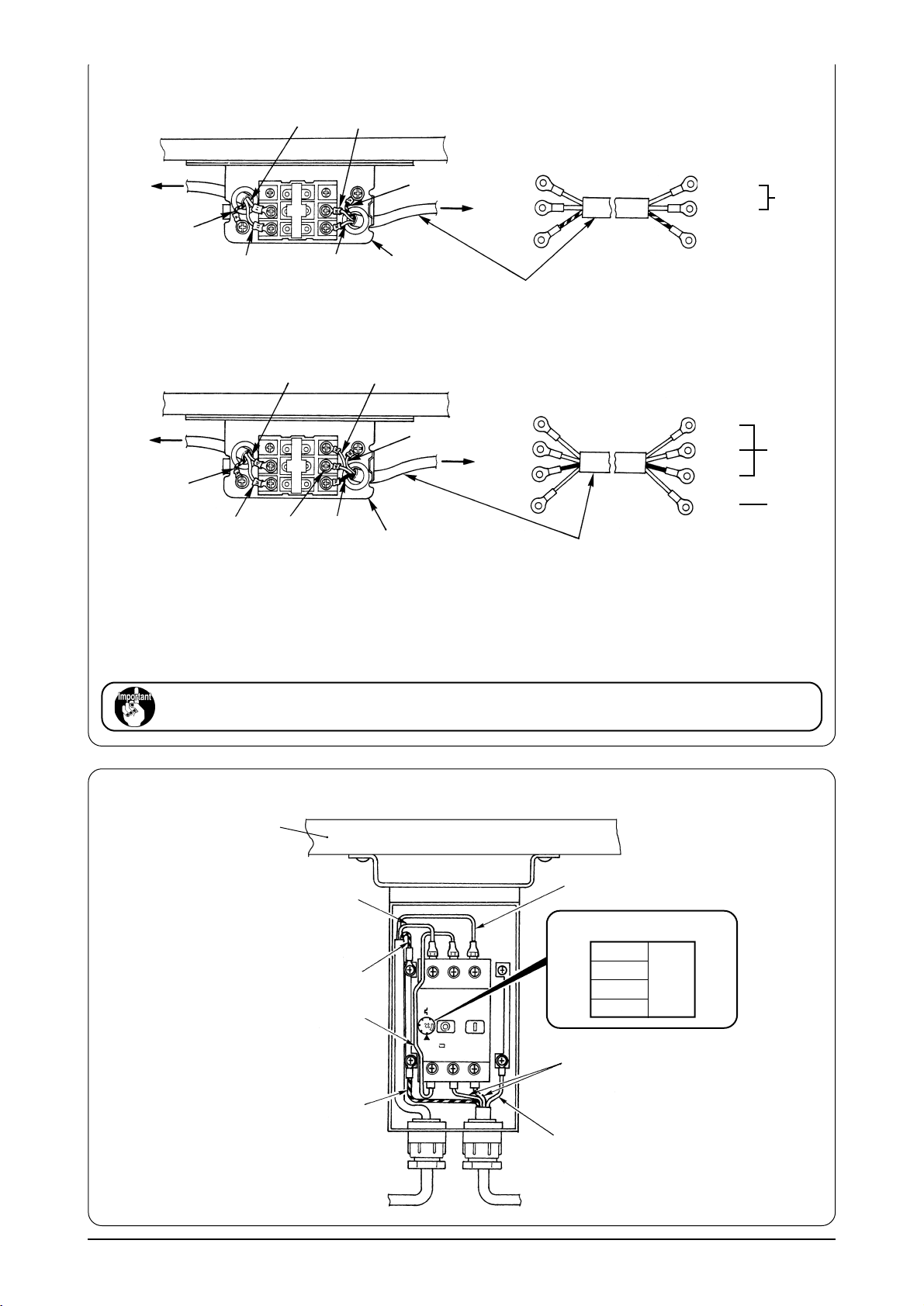
• Connection of single phase 200 to 240V
Brown
Light blue
Power switch
Light blue
Table
Sewing
machine
head
Green/yellow
Brown
• Connection of 3-phase 200 to 240V
Light blue Red
Table
Sewing
machine
head
Green/yellow
Brown
White
Black
Power switch
Green/yellow
Plug
Green
Plug
Power cable
Power cable
Brown
Light blue
Green/yellow - GND
Red
White
Black
Green GND
AC 200V
to
AC240V
AC 200V
to
AC 240V
When voltage of 100 to 120V is used, connect the input change-over connector of CN32 mounted on
the PWR circuit board to 100V side.
When voltage of 200 to 240V is used, connect the input change-over connector to 200V side.
If the setting of CN32 connector is mistaken, the control box is likely to be broken.
Never use under the wrong voltage and phase.
(4) Power switch
Table
Brown
Light blue
Ampere set value
200 V
Green/Yellow
Black
220 V
230 V
240 V
2.0 A
Green/Yellow
Sewing machine head
Black
Light blue
Plug
INSTALLATION
5
Page 8
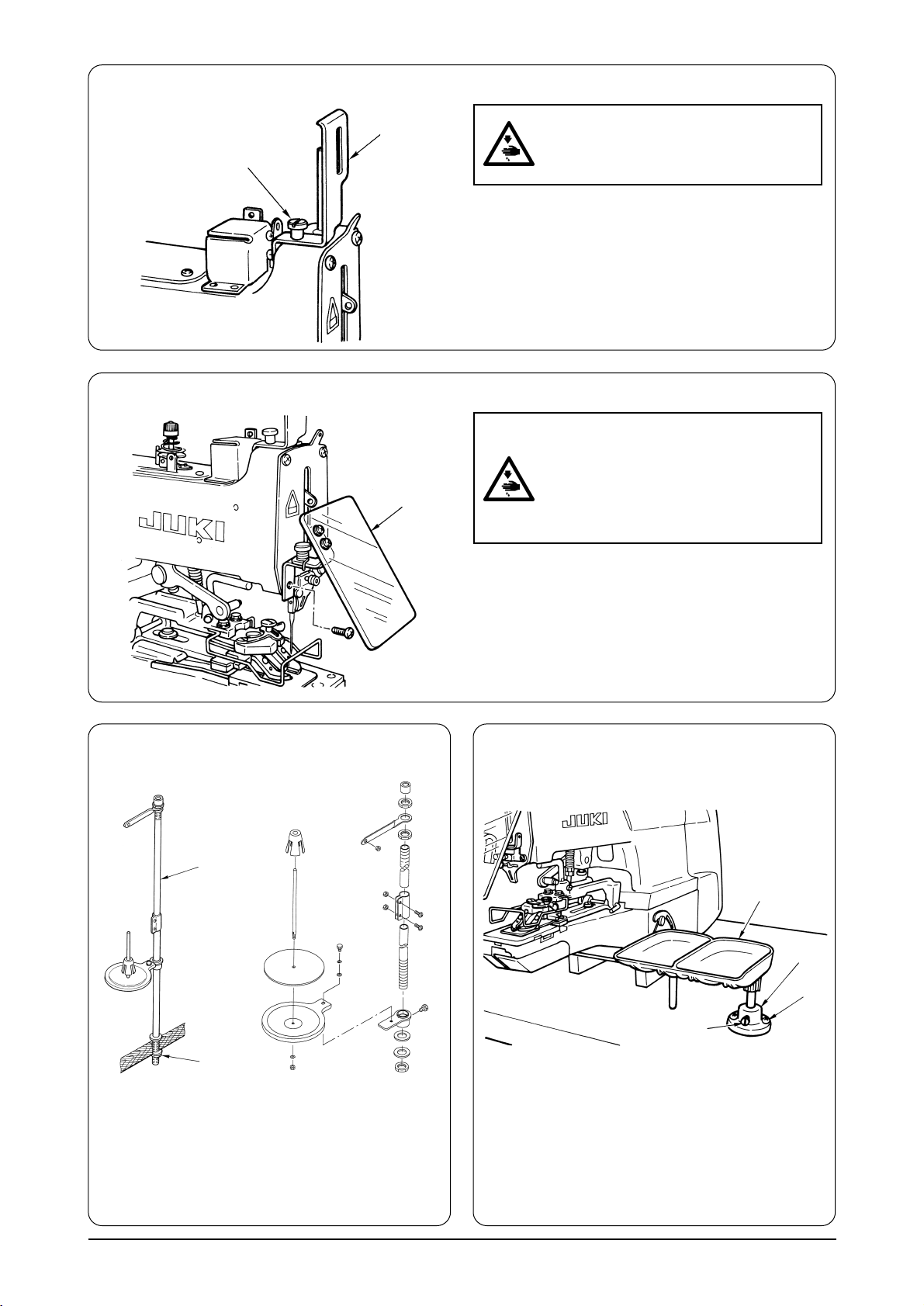
(5) Attaching the needle bar cover
1
2
(6) Installing the eye protection cover
1
WARNING :
Turn OFF the power before starting the
work so as to prevent accidents caused
by abrupt start of the sewing machine.
Loosen setscrew 2 and fix needle bar cover 1
supplied with the machine as shown in the figure.
WARNING :
Be sure to attach this cover to protect
the eyes from the dispersion of needle
breakage.
Turn OFF the power before starting the
work so as to prevent accidents caused
by abrupt start of the sewing machine.
Be sure to install eye protection cover 1 and
use the sewing machine.
(7) Installing the thread stand
2
1
1) Assemble the thread stand unit, and set it in
the hole located at the upper right of the table.
2) Tighten locknut 1 to fix the thread stand.
3) For ceiling wiring, pass the power cord
through spool rest rod 2.
(8) Attaching the button tray
4
1
2
3
1) Fix base 1 on the table with wood screw 2.
2) Insert the button tray 4 in the hole of base 1
and fix with setscrew 3.
6
INSTALLATION
Page 9
$. PREPARATION OF THE SEWING MACHINE
1. Attaching the needle
WARNING :
Turn OFF the power before starting the work so as to prevent accidents caused by abrupt start of the
sewing machine.
☆ The needle of TQx7 #16 is attached to the sewing
machine.
1
2
Loosen setscrew 1 and hold needle 2 with its
long groove facing to this side. Insert needle 2 up
into the needle hole in the needle bar until it comes
in contact with the deepest end of the needle hole
and tighten setscrew 1.
2. Threading the machine
WARNING :
Turn OFF the power before starting the work so as to prevent accidente caused by adrupt start of the
sewing machine.
Thread the machine in the order as illustrated.
Finally, pass the thread through the needle eye by approximately 60 to 70 mm.
5
3
9
!1
!3
!2
!0
8
7
6
4
2
2
1
1
!6
!5
!4
5
6
7
PREPARATION OF THE SEWING MACHINE
4
3
7
Page 10

%. OPERATION OF THE SEWING MACHINE
1. Names of the operation panel switches
1 Set ready switch
This switch is used when making the sewing
machine from setting status to sewing possible
status.
2 Button clamp lifting switch
This switch performs up/down of the button
clamp.
3 Stitch shape selection LED
4 Stitch shape selection switch
This switch is used when changing the stitch
shape.
5 + / Forward switch
This switch increases the set value or performs
traveling forward when confirming the feed.
6 − / Backward switch
This switch decreases the set value or performs
traveling backward when confirming the feed.
7 Item selection switch
This switch is used when selecting the item
desired to be changed.
8 Item selection LED
9 Reset switch
This switch returns the various set values to
the original status or performs release when
an error occurs.
!0 Display section A
8
OPERATION OF THE SEWING MACHINE
Page 11

2. Pattern table
Three same sewing sizes and numbers of stitches for each stitch shape have been stored in pattern Nos. 1 to 51
at the time of delivery. By selecting sewing size and number of stitches from the table below, the stitch shape
can be changed to the three different kinds of patterns of the same stitch shape and be stored in memory.
Pattern No.
1
2
3
4
5
6
7
8
9
10
11
12
13
14
15
16
17
18
19
20
21
22
23
24
25
26
27
28
29
30
31
32
33
34
35
36
37
38
39
40
41
42
43
44
45
46
47
48
49
50
51
Stich shape
4-holed
( , crossover stitch : with)
4-holed
( , crossover stitch : without)
4-holed
( X, crossover stitch : with)
4-holed
( X, crossover stitch : without)
4-holed
( Z, crossover stitch : with)
2-holed (crosswise)
2-holed (lengthwise)
4-holed
( , crossover stitch : with)
4-holed
( , crossover stitch : without)
3-holed ( )
3-holed ( )
3-holed ( )
3-holed ( )
2-holed
(crosswise) label attaching
Wrapped-around
(crosswize size : 4 mm)
Wrapped-around
(crosswise size : 5 mm)
Wrapped-around
(crosswise size : 6 mm)
Stich size (mm) Number of stitches
Initial value
2.6
2.6
2.6
2.6
2.6
2.6
2.6
2.6
2.6
2.6
2.6
2.6
2.6
10.0
2.6
2.6
2.6
Range
2.0 to 6.5
2.0 to 6.5
2.0 to 6.5
2.0 to 6.5
2.0 to 6.5
2.0 to 6.5
2.0 to 6.5
2.0 to 6.5
2.0 to 6.5
2.6, 2.8, 3.0
2.6, 2.8, 3.0
2.6, 2.8, 3.0
2.6, 2.8, 3.0
6.0, 8.0, 10.0
0.0 to 6.5
0.0 to 6.5
0.0 to 6.5
Unit
0.2
0.2
0.2
0.2
0.2
0.2
0.2
0.2
0.2
0.2
0.2
0.2
0.2
2.0
0.2
0.2
0.2
Initial value
15
16
15
16
15
8
8
15
16
17
17
17
17
5
16
16
16
Range
15, 19, 23, 27
16, 20, 24, 28
15, 19, 23, 27
16, 20, 24, 28
15, 19, 23, 27
8, 10, 12, 14
8, 10, 12, 14
15, 19, 23, 27
16, 20, 24, 28
17, 23
17, 23
17, 23
17, 23
5, 7
6, 10, 16
6, 10, 16
6, 10, 16
OPERATION OF THE SEWING MACHINE
9
Page 12

3. Operating procedure of the operation panel (basic volume)
6
1
2
4
7
5
3
(1) Turn ON the power switch.
(2) Select the stitch shape.
Press stitch shape selection switch 1 and LED moves.
Stop the representative stitch shape at the position where the LED lights up, and place the other stitch
shapes at the position of .
(3) Determine the pattern.
Press +/− switches 2 at the position where the LED lights up, and the pattern No. will be displayed
at display section A 3.
For the pattern No. and the stitch shape, refer to the table on P.9.
(4) Select the number of stitches.
Press item selection switch 4 so that the LED comes to the position of .
The number of stitches set in advance with the pattern No. will be displayed at display section A 3.
Here, press + / − switches 2 to change the number of stitches.
Number of stitches cannot select the combination other than that set in advance.
(5) Determine the sewing pitch.
Press item selection switch 4 so that the LED comes to the position of .
The sewing pitch set in advance with the pattern No. will be displayed at display section A 3.
Here, press + / − switches 2 to change the the sewing pitch.
Sewing pitch can be changed 2 to 6.5 mm in increments of 0.2 mm.
(6) Determine the number of revolution
Press item selection switch 4 so that the LED comes to the position of and “ ” will be
displayed at display section A 3. This means 18 x 100 = 1,800 sti/min. The digits less than 100 sti/min
are omitted and displayed in case of this machine.
Here, press + / − switches 2 to change the number of revolution.
10
OPERATION OF THE SEWING MACHINE
Page 13

(7) Check the needle entry point.
Press set ready switch 5, the machine confirms the position of the origin and the button clamp
is in the state of being lifted. At this time, insert the button.
Press button clamp lifting switch 6 to lower the button clamp.
Press +/− switches 2 and the feed moves forward/backward. Then check the needle entry point.
At this time, “ ” is displayed at display section A 3.
When lowering needle, turn the hand pulley referring to P.15.
(8) Perform sewing.
When checking of the needle entry point is completed, press reset switch 7.
The button clamp goes up in this state. It is in the sewing possible state.
Set a button and the cloth to the machine and depress the starting pedal.
4. Stitching without the crossover thread
When the optional without-crossover-thread device is installed, it is possible to perform stitching without
crossover thread in case of stitch shapes of , X and . Even when the device is not installed, thread
trimming is performed during sewing if a pattern No. without crossover thread is selected.
The selection LED corresponding to the stitch shape flashes on and off, and the stitch shape without crossover
thread can be discriminated.
5. Operating procedure of the operation panel (applied volume)
6
1
2
4
7
(1) Cycle stitching
The button can be sewn in the predetermined order with the max. 15 different kinds of sewing methods.
For example, the button can be repeatedly sewn in the order of , X and Z.
To call the cycle stitching can be performed by lighting up the LED of pattern No. with item selection
switch 4 and pressing + switch 8. The cycle stitching is arranged at the last of pattern No., is
arranged the next pattern of No. 51 unless the external ROM is provided, and “ ” is displayed at display
section A 3.
In this state, press set ready switch 5, and “ ” will be displayed at display section A 3.
Then sewing is performed in the order of the max. 15 kinds of sewing conditions (P1 to PF) that have been
programmed in advance.
5
8
3
OPERATION OF THE SEWING MACHINE
11
Page 14

6
5
1
2
4
7
8
3
(2) Registration of the pattern of the cycle stitching
1) To register the pattern, press item selection switch 4 for two seconds to flash the item selection
LED located at . “ ” is displayed at display section A 3.
In this state, press again item selection switch 4 and “ ” will be displayed at display section A 3.
Press once more item selection switch 4 to light up the item selection LED of the pattern No.
and display the pattern No. you desire to register at display section A 3 using + / − switches 2.
In this state, the pattern No. is recorded to P1. Press again item selection switch 4 to display
“ ” at display section A 3 and press + switch 8, then display will be changed to “ ”.
2) Press again item selection switch 4 to light up the LED of pattern No. and display the pattern
No. you desire to register in the second place at display section A 3 using + / − switches 2.
If “ ” is displayed at display section A 3 when the item selection LED of the pattern No. lights up,
the pattern is in the state of not being inputted. When the item selection switch 4 is pressed, P
number and pattern No. are alternately displayed at display section A 3.
3) It is not possible to advance to the input of the next P2 unless pattern No. is inputted to P1.
Register the patterns after P3 by the same operation. It is possible to register up to PF maximumly.
When the registration of the pattern is completed, press item selection switch 4 for two seconds to
return to the normal setting state. At this time, “ ” is displayed at display section A 3 and the cycle
stitching has been selected.
In addition, for the sewing of cycle stitching, P1 to PF can be changed in the set ready state using +/−
switches 2. In this state, when item selection switch 4 is pressed, the item selection LED of pattern
No. lights up and pattern No. is displayed at display section A 3.
4) To delete the registered pattern, set the display of the pattern No. to “ ”.
(3) Sewing of button of stitch shapes other than the representative stitch shapes and
that of stitch shapes by ROM data created by PGM-20
Make the LED of light up with stitch shape selection switch 1 and select the stitch shapes after
pattern No. 52. When the pattern of the external ROM is selected, all the LEDs which display the stitch
shape light up.
The shape data has been stored in the pattern Nos. 1 to 51 beforehand. However, if the same number
exists in the pattern Nos. of the external ROM, the shape of the external ROM is selected.
12
OPERATION OF THE SEWING MACHINE
Page 15

6. How to use the memory switch
1) The speed up to 3rd stitch can be set so that the sewing speed at the start of sewing is controlled and the
stitch is stabilized.
2) Effective/ineffective of the knot-tying functon can be selected.
3) Operating/non operating of the wiper can be selected.
In case the wiper is installed and set to the non-operating setting, when the pattern without crossover
thread is selected, the wiper works only when the crossover thread is trimmed, and it does not work after
thread trimming at the time of completion of sewing.
In case of the pattern with crossover thread as well, the wiper does not work after thread trimming at the
time of completion of sewing with this setting.
In case of the setting of operating the wiper, the wiper always works at the time of thread trimming.
(1) Starting of the memory switches
In the state that +/− switches 2 are simultaneously
pressed, turn ON the power, and the memory switches
5
are in the state of setting.
At this time, “ ” is displayed in display section A 3.
Press set ready switch 5 and all 5 stitch shape
selection LEDs 9 flash on and off. This state means
that the memory switches are being inputted.
!0
1
2
6
9
8
3
4
7
(2) Setting procedure of the memory switches
There are the memory switches 1 to 8.
Switch No. “ ” is displayed in the display section A 3 and item selection LED !0 of the pattern No.
lights up. In this state, press item selection switch 4, and the memory switch No. and the description
are alternately displayed in display section A 3.
In the state that the memory switch No. is displayed, press the + switch 8 and the memory switch No.
increases by one.
When the description of the memory switch is displayed, item selection LED !0 of the pattern No.
goes off.
Switch No.
1
2
3
4
Speed of 1st stitch of soft start
Speed of 2nd stitch of soft start
Speed of 3rd stitch of soft start
Speed of 1st stitch after trimming crossover thread
Description
Initial setting
18 *100 [sti/min]
18 *100 [sti/min]
18 *100 [sti/min]
18 *100 [sti/min]
Setting range
4 to 18
4 to 18
4 to 18
4 to 18
400 to 1,800 sti/min
400 to 1,800 sti/min
400 to 1,800 sti/min
400 to 1,800 sti/min
Remarks
5
6
7
8
Speed of 2nd stitch after trimming crossover thread
Speed of 3rd stitch after trimming crossover thread
Knot-tying function 0 : Ineffective 1 : Effective
Wiper operation 0 : Non operating 1 : Operating
18 *100 [sti/min]
18 *100 [sti/min]
1 (Operating)
0 (Non operating)
4 to 18
4 to 18
0.1
0.1
400 to 1,800 sti/min
400 to 1,800 sti/min
When setting is completed, turn OFF the power. Return ON the power to return to the normal setting state.
OPERATION OF THE SEWING MACHINE
13
Page 16

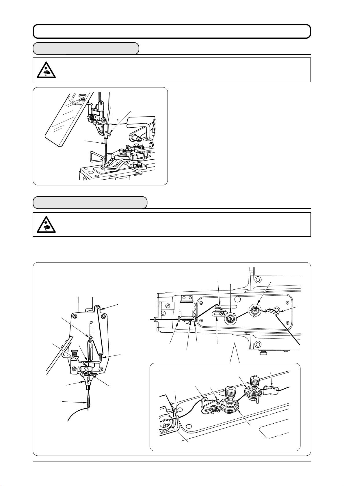
. ADJUSTMENT OF THE SEWING MACHINE
Ⅵ
1. Thread tension adjustment
Tension post No.1 ❶ is used to adjust the thread
tension to sew on the button and a relatively low
tension will be enough.
Tension post No.2 ❷ is used to adjust the thread
tension applied to the root of the button sewing
stitches. This tension must be higher than that of the
tension post No.1 and be adjusted according to the
sewing conditions.
Turn the respective nuts clockwise to increase
the thread tension.
Decrease
❷
Decrease
Increase
Increase
❶
2. Adjustment of thread hauling amount
Adjustment of thread hauling amount is performed
by loosening setscrew ❶ and move the position of
B
❶
❷
A
A
thread guide ❷.
When the end of thread is drawn from arrow hole A
in the button after sewing, move the thread guide in
the direction of A in the gure, and the end of thread
is drawn from arrow hole B in the button, move it
in the direction of B in the gure so that the end of
thread is not drawn.
B
3. Timing of thread tension release
Turn the hand pulley as you draw the thread in the
direction of the arrow as illustrated and you will nd a
point at which the tension disk on tension post No.2
releases the thread. At this moment, the standard
distance from the top end of the needle bar bushing
(upper) to the top end of the needle bar is 54 to 56
mm. Perform the following adjustments especially
when the undermentioned troubles occur frequently.
Loosen nut ❶, insert the blade of a screwdriver
to the top slot of tension post No.2, and turn it in
❶
Phenomenon Height of needle bar
1. When the stitch made on the wrong side of the work-piece is too loose ; Make the needle bar slightly higher.
2. When the thread is broken during sewing ; Make the needle bar slightly higher.
3. When the thread is broken frequently ; Make the needle bar slightly lower.
the direction of the arrow to decrease the height
of the needle bar, or in the reverse direction of
the arrow to increase it.
14
ADJUSTMENT OF THE SEWING MACHINE
Page 17

4. Adjustment of the thread tension guide on the face plate
When the machine fails to form a seam at the start
of sewing and starts to form it after it has run a while,
❶
adjust the thread tension guide on the face plate if
the aforementioned trouble cannot be corrected by
adjusting the thread pull-off lever.
1) If the machine fails to form a seam at the
start of sewing, reduce the thread tension by
turning thumb nut ❶ (double nut).
5. Adjustment of needle-to-looper relation
WARNING :
Turn OFF the power before starting the work so as to prevent accidents caused by abrupt start of
the sewing machine.
Slightly loosen knob ❶ located on the right side of
❷
❶
the sewing machine, turn cover ❷ in the direction of
the arrow, and you will nd hand pulley ❸ inside it.
The rotating direction of this pulley is in the direction
of the arrow.
❸
1) Turn hand pulley
to the lowest point of its stroke and loosen
❺
setscrew ❹.
to bring down needle bar
❸
2) Adjust the height of the needle bar using top two lines engraved on the needle bar for the TQx1
needle and using bottom two lines for the TQx7 needle. Align the upper engraved line A with
the bottom end face of needle bar bushing (lower) ❻ and tighten setscrew ❹.
3) Loosen setscrew
and turn the pulley ❸ in the normal sewing directionuntil lower engraved
❼
line B aligns with the bottom end face of needle bar bushing (lower) ❻.
4) By keeping the machine in this state, align looper blade
with the center of the needle and
❽
tighten setscrew ❼.
5) Loosen setscrew
6) When the adjustment is completed, return cover
❹
❺
❻
TQx1 needle {
TQx7 needle {
and provide a 0.05 to 0.1 mm clearance between the needle and looper.
❾
to the home place and tighten knob ❶.
❷
❻
❽
A
❺
B
❾
❼
ADJUSTMENT OF THE SEWING MACHINE
15
Page 18

6. Adjustment of the needle guide
WARNING :
Turn OFF the power before starting the work so as to prevent accidents caused by abrupt start of the
sewing machine.
Loosen screw 2 and provide a 0.05 to 0.1 mm
2
1
0.05 to 0.1 mm
clearance between the needle and needle guide 1 by
moving needle guide 1 to the left or the right when
the needle bar is in the lowest position of its stroke.
7. Adjustment of the thread trimming mechanism
WARNING :
Turn OFF the power before starting the work so as to prevent accidents caused by abrupt start of the
sewing machine.
(1) Adjusting the position of the moving
2
knife
1
6
3
8
9
Top end of thread separation nail
1
5
4
0.5 to 0.7 mm
1) Remove cover 1 using setscrew 2.
2) Lift the presser lifting lever to such an extent
that roller 4 and hook 5 of presser lifting lever
3 come in contact with each other to move
thread trimming connecting plate A 9 to its
most advanced position, and insert spanner 6
as illustrated.
3) Insert gauge 7 into the end face of the slit in
throat plate, loosen screw 8, press the top end
of thread triming connecting plate A 9 to gauge
7, and tighten screw 8.
7
(2) Adjusting the moving knife thread
separation nail
Bend thread separation nail 1 using a screwdriver
or the like and adjust so that a clearance of 0.5 to
0.7 mm should be provided between thread
separation nail 1 and looper 2.
16
2
ADJUSTMENT OF THE SEWING MACHINE
Page 19

8. Adjusting the height of the button clamp unit
WARNING :
Turn OFF the power before starting the work so as to prevent accidents caused by abrupt start of the
sewing machine.
1) Insert a thing of 10 mm thick into A and make
3
A
button clamp jaw lever 1 in the state of being
lifted.
2) Loosen screw 2 and tighten it to fix button
clamp lifting hook 3 in the state that button
clamp lifting hook 3 is pressed to the lower
side.
2
1
9. Adjusting the work pressing force
WARNING :
Turn OFF the power before starting the work so as to prevent accidents caused by abrupt start of the
sewing machine.
1
4 to 5 mm
2
For the optional label attaching type, the
button clamp jaw lever can be lifted up to 14
参考
mm for use.
The standard work pressing force is obtained by turning
nuts 1 and providing a 4 to 5 mm clearance between
the bottom face of two nuts 1 and the bottom end of
the screw of pressure adjusting bar 2.
10. Adjustment of the button clamp stop lever
WARNING :
Turn OFF the power before starting the work so as to prevent accidents caused by abrupt start of the
sewing machine.
1)
Loosen clamp screw 1, place a button correctly
1
2
3
in the sewing position and adjust button clamp
stop lever 2 to permit the button properly to
rest on button clamp jaw levers 3.
2) Next, tighten clamp screw 1 after determining
the distance between the left and right jaw
levers.
ADJUSTMENT OF THE SEWING MACHINE
17
Page 20

11. How to adjust the position of the feed origin
WARNING :
Turn OFF the power before starting the work so as to prevent accidents caused by abrupt start of the
sewing machine.
In case you desire to adjust the position of the feed when replacing the attachment, it is possible to fix feed
plate 1 to the position of the origin.
2
2
1
1) First, remove hinge screw 2 fixing the needle bar cover.
2) Next, align the hole of feed plate 1 with the hole of the top surface of the machine bed.
3) When hinge screw 2 is entered and fixed here, the place becomes the position of the feed origin.
By fixing the various attachments at the center position, the attachments can be used only by
confirming the needle entry point under the feed mode (see P.11) when turning ON the power.
4) After the adjustment, remove and return hinge screw 2 to the home place, and fix the needle bar
cover.
Be sure not to forget removing hinge screw 2 after the adjustment. If not, an error will be displayed
when pressing the set ready switch at the time of turning ON the power.
In addition, be sure to fix the needle bar cover.
18
ADJUSTMENT OF THE SEWING MACHINE
Page 21

12.
Installing the save button bar (accessory part) (MB-1800, MB-1800B)
WARNING :
Turn OFF the power before starting the work so as to prevent accidents caused by abrupt start of the
sewing machine.
1) Install save button bar mounting plate 3 on button
clamp base 1 with screw 2.
2) Adjust so that a clearance of 3.5 to 4 mm is
provided between the center of the button and the
top end of the save buton bar.
3) To adjust the raising amount of the save button
bar, loosen screw 4, and move the save button
bar up or down.
3
4
2
1
3.5 to 4 mm
13. Adjusting the wiper (Optional for MB-1800)
WARNING :
Turn OFF the power before starting the work so as to prevent accidents caused by abrupt start of the
sewing machine.
The standard thread catching point at the top end of
the wiper should be 3 to 4 mm away from the tip of the
needle and 18 to 20 mm away from the center of the
needle at the stop position of the sewing end.
1
2
3 to 4 mm
Make the adjustment using four screws 1 which fix
the wiper magnet in place and screw 2 which fixes
the wiper mounting base.
18 to 20 mm
ADJUSTMENT OF THE SEWING MACHINE
19
Page 22

&. ATTACHMENTS
Use
MB-1800
Schematic
drawing
Remarks
Use
MB-1800
Schematic
drawing
Remarks
Large-size
14617559
A
B
Button size :
A : 0 to 6.5 mm
B : φ20 to φ 28 mm
Snaps
14617955
A
Snap size :
A : 8 mm
Flat buttons
Medium-size
D2529373B00A
A
B
Button size :
A : 0 to 4.5 mm
B : φ12 to φ 20 mm
Wrapped-around buttons
First process
B24473720A0
A
Thread shank height :
A : 5.5 mm
Small-size
B2529373000
A
B
Button size :
A : 0 to 3.5 mm
B : φ10 to φ 12 mm
Second process
MAZ046010A0
Shank buttons
General
14617658
Button diameter :
Less than 16 mm
Shank size :
Thickness : 5 to 6 mm
Width : 2.5 to 3 mm
Metal buttons
General
14618052
Luis type
14617757
Button size :
Same as 14617658,
but possible to sew
buttons having
some variations of
shank in shape.
Stay button
MAZ039010A0
Use
MB-1800
Schematic
drawing
Remarks
Labels
14618151
Stitch width :
Max. 10 mm
WARNING :
Turn OFF the power before starting the work so as to prevent accidents caused by abrupt start of the
sewing machine.
1
In order to install the attachmenton the machine, you
may have to remove the button clamp mechanism 1
or feed plate 2. Dislocate a snap ring from button
clamp installing stud 3, and you will be able to remove
button clamp mechanism assembly 1. Remove
setscrews 4, and you can remove feed plate 2.
2
20 ATTACHMENTS
3
4
Page 23

1. Attachment for shank buttons (pearl buttons) (14617658, 14617757)
WARNING :
Turn OFF the power before starting the work so as to prevent accidents caused by abrupt start of
the sewing machine.
(INSTALLATION)
!1
4
@0
5
!0
1
3
7
!4
2
!5
!3
!8
6
!6
8
9
!2
!9
!7
(ADJUSTMENT AND OPERATION)
1) Loosen screw !2, let feed plate 6 recede 0.5 to 1.0 mm from the left end of button clamp jaw
lever 2 and retighten screw !2.
2) Set a button in place, loosen screws !3 and !4, and align shank button holding clamp !5 with
the center of the button.
3) Shank button holding clamp !5 must give proper pressure to the button so that the button stays
steadily in position while being sewn. Loosen a setscrew in thrust collar !6 and rotate the thrust
collar until shank button holding clamp !5 provides proper pressure.
4) Youmayxbuttonclampblock!7 in a convenient position for operation.
Rem ove bot h th e but ton cla mp mech anism
assembly and the feed plate from the machine
and install attachment 1 for pearl button in place.
Loosen screws 3 and adjust button clamp bracket
to permit the needle to come down in the middle
4
of the needle slot in shank button adaptor 2.
Attach button clamp feed plate 5 using screws 7
in the way that it permits the needle to come down
in the middle of the needle slot in feed plate 6.
Insert the top end of button clamp stud 8 into an
opening in the jaw of the machine arm and fasten
it by screw 9.
(When attaching 14617757, you must change also
button clamp pressure adjusting bar !0 and button
clamp stopper pin !1 at the same time.)
1. Whenyouxthethrustcollar,ensurethatbuttonclamprotatingshaft!8doesnotplayaxially
in its bracket.
2. Adjust lifting hook @0 and stopper pin !1 so that L-shaped lifting rod roller !9 does not come in
contact with button clamp bracket 4.
2.
Attachmentfortherstprocessofwrapped-aroundbuttons(B24473720A0)
WARNING :
Turn OFF the power before starting the work so as to prevent accidents caused by abrupt start of
the sewing machine.
(INSTALLATION)
2
3
1
Attach wrapped-around button foot 1 to the
ordinary button clamp jaw levers using screw 2
and guide pin screw 3.
At this time, align foot 1 with the jaw levers so that
they permit a button to rest in the middle.
(ADJUSTMENT AND OPERATION)
Adjustment and operation are almost same as those
for the at buttons, but you must adjust the thread
guide to provide more hauling amount of thread in
order to make the thread loose below the button for
thread shank formation.
(See
“ ^-2. Adjusting the hauling amount of thread ”
.)
ATTACHMENTS
21
Page 24

3.
Attachment for the second process of wrapped-around buttons (MAZ046010A0)
WARNING :
Turn OFF the power before starting the work so as to prevent accidents caused by abrupt start of the
sewing machine.
3
2
1
Remove the button clamp mechanism assembly,
button clamp pressure adjusting bar and feed plate
from the machine, and install attachment for the
second process of wrapped-around buttons 1.
4
(ADJUSTMENT AND OPERATION)
(INSTALLATION)
1) Loosen screw 2 and adjust the thread shank length by moving guide (large) 3 and guide (small)
4 in line with the point of of needle entry.
2) Set a button (tilt it slightly for easy insertion) and the thread as the arrow shows.
4. Attachment for snap (14617955)
WARNING :
Turn OFF the power before starting the work so as to prevent accidents caused by abrupt start of the
sewing machine.
(INSTALLATION)
Remove the button clamp mechanism assembly
and the feed plate. Set the stitch length to 4 mm
by means of the panel operation. Install snap clamp
feed plate 1 in the way that the needle drops
evenly at four corners of its square opening.
Install snap attachment assembly 2 on the
machine, place a snap on the snap clamp jaw
levers and make sure that the needle drps
accurately in each hole in the snap. If necessary,
loosen hex head screws 3 and adjust the position
accurately.
Lastly, make sure that the concave section on the
bottom face of snap clamp slide guide 4 accuratly
matches the convex section of snap clamp feed plate
1.
4
2
3
1
22 ATTACHMENTS
Page 25

5. Attachment for metal buttons (14618052)
WARNING :
Turn OFF the power before starting the work so as to prevent accidents caused by abrupt start of the
sewing machine.
(INSTALLATION)
9
4
5
!9
!8
1
3
7
!2
2
!3
!1
6
!4
!6
8
!0
!7
!5
(ADJUSTMENT AND OPERATION)
1) Loosen screw !0, let feed plate 6 recede 1.0 to 1.5 mm from the left end of button clamp jaw lever
2 and retighten screw !0.
2) Set a button in place, loosen screws !1 and !2 and align metal button holding clamp !3 with the
center of the button.
3) Metal button holding clamp !3 must give proper pressure to the button so that the button stays
steadily in position while being sewn. Loosen a setscrew in thrust collar !4 and rotate the thrust
collar until metal button holding clamp !3 provides proper pressure.
4) You may fix button clamp block !5 in a convenient position for operation.
Remove both the button clamp mechanism
assembly and the feed plate from the machine, and
install attachment 1 in place. Loosen screws 3
and adjust button clamp bracket 4 to permit the
needle to come down in the middle of the needle
slot in metal button adaptor 2.
Attach button clamp feed plate 5 using screws 7
in the way that it permits the needle to come down
in the middle of the needle slot in feed plate 6.
Insert the top end of button clamp stud 8 into an
opening in the jaw of the machine arm and fasten
it by screw 9.
1. When you fix the thrust collar, ensure that button clamp rotating shaft !6 does not pay axially in
its bracket.
2. Adjust lifting hook !9 and stopper pin !8 so that L-shaped lifting rod roller !7 does not come in
contact with button clamp bracket 4.
ATTACHMENTS
23
Page 26

*. ERROR LIST
Error LED located on the left side of the reset switch flashes on and off or lights up when an error
occurs. When the LED lights up, the setting state will be made by pressing the reset switch and the
error will be released. Error No. will be displayed in the display section A.
Error No.
01
02
03
04
05
06
07
09
10
11
12
Item
Trouble of sewing data
Trouble of 24V voltage
Dislocation of needle up-position
Dislocation of presser down detection
Trouble of presser solenoid
Trouble of servo encoder
Servo motor lock
System trouble
Trouble of stepping motor origin 1
Trouble of stepping motor origin 2
Overload of servo motor
Description
Pattern has not been inputted in the program of cycle stitching.
Trouble of power voltage, trouble of load on main shaft of machine head, trouble of
PWR circuit board
Trouble of load on main shaft of machine head, trouble of encoder,or loosenes of
encoder fixing screw
Foreign materials under presser, dislocation of presser down sensor, or defective
down sensor
Defective solenoid, dislocation of presser up sensor, or defective up sensor
Defective encoder or improper fixing of encoder
Trouble of load on main shaft of machine head, or defective servo motor
Defective control circuit board or defective program ROM
Trouble of origin sensor 1, dislocation of sensor, or trouble of load on stepping
motor 1 (left side of operator)
Trouble of origin sensor 2, dislocation of sensor, or trouble of load on stepping
motor 2 (right side of operator)
Trouble of load on main shaft of machine head (short time), or defective servo
motor
13
16
17
18
19
30
31
32
33
EE
Overload of servo motor
Trouble of nember of revolution
Trouble of servo voltage
Trouble of temperature
Overcurrent of servo motor
Trouble of external ROM
Trouble of external ROM
Trouble of external ROM
Trouble of external ROM
Temperature rise
H
Trouble of memory
Trouble of load on main shaft of machine head (long time), or defective servo
motor
Defective control circuit board, defective encoder, or defective servo motor
Defective PWR circuit board
Cleaning of fan filter, excessive load on main shaft, or trouble of control circuit
board (high temperature of pre-driver)
Defective servo motor, or improper timing of encoder
ROM formatting error
Number of stitches (99) is over.
Moving amount of one stitch (lengthwise : 6.5 mm, crosswise : 10 mm) is over.
Outside of sewing possible area
Cleaning of fan filter, defective fan operation, or defective control circuit board
(temperature detection)
Defective control circuit board (EEPROM)
(Note) Error Nos. 01, 03, 04, 31, 32, and 33 return to the state before the occurrence of the error by pressing
the reset switch.
24
ERROR LIST
Page 27

(. TROUBLES AND CORRECTIVE MEASURES
No.
The machine fails
1
to sew at the start
of sewing.
2
Thread breakage
3
Buttons are not
sewn tightly.
4
Thread cannot be
trimmed.
TROUBLES
CAUSES
Length of remaining thread is too short.
Speed is fast.
The thread tension post No. 2 fails to
release the thread at correct timing.
The needle does not enter the center of
the holes in the button.
The needle is too thick for the diameter of
the hole in the button.
The thread tension post No. 2 fails to
release the thread at correct timing.
The thread tension post No. 2 does not
give sufficient tension.
The needle does not enter the center of
the holes in the button.
The moving knife does not separate the
thread on the fabric with its separation nail.
The needle does not enter the center of
the holes in the button.
CORRECTIVE MEASURES
Adjust the thread adjusting thread guide.
Use the soft-start function.
Make the thread releasing timing slightly earlier.
Adjust the position of the button clamp jaw lever
holder.
Replace the needle with a thinner one.
Make the thread releasing timing slightly earlier.
Increase the tension of the thread tension post
No. 2.
Adjust the position of the button clamp jaw lever
holder.
Adjust the position of the moving knife.
Adjust the position of the button clamp jaw lever
holder.
5
Needle thread is
cut in two places.
The last stitch skips.
The moving knife separation nail is too
high or too low.
The moving knife does not separate the
thread on the fabric with its separation nail.
The moving knife separation nail is too
high or too low.
Adjust the looper.
Adjust the height of the thread separation nail.
Adjust the position of the moving knife.
Adjust the height of the thread separation nail.
TROUBLES AND CORRECTIVE MEASURES
25
Page 28

). OPTIONAL
1. Installing the without-crossover-thread device (Part No. : M85126300A0)
WARNING :
Turn OFF the power before starting the work so as to prevent accidents caused by abrupt start of the
sewing machine.
1
3
2
1) Remove top cover 1.2)Remove screws 2 with spanner and remove
adjusting plate 3.
6
5
1
4
3) Install thread adjusting solenoid (asm.) 4 on
top cover 1 with screw 5.
7
9
!0
8
4) Install wiper solenoid (asm.) 6 as illustrated.
5) Remove the rubber cap in the top cover, enter cords 7 and 8 inside the top cover, and draw out
the cords on the electrical component cover side. Connect thread adjusting solenoid connector
(black) 9 and wiper solenoid connector (yellow) !0.
6) After completion of connection of the connectors, install the electrical component cover.
26
OPTIONAL
Page 29

_. DRAWING OF THE TABLE
R4
R4
570
500
R4
R4
17 drilled hole
R30
R30
R4
40
R4
105
115
35
Stand installing hole
4-2 drilled hole, depth 10 (bottom surface)
40 drilled hole
810
980
3-8 drilled hole
30 drilled hole
Installing position of stopper for drawer
525
(6)
120
R4
R4
R30
2 drilled hole, depth 10 (bottom surface)
220
360
160
78.5
63
112
190
2126
46
110
Main switch installing position
2-2 drilled hole, depth 10 (bottom surface)
1050
Installing position of drawer
2 drilled hole, depth 10 (bottom surface)
15
160
390
DRAWING OF THE TABLE
R30
27
 Loading...