

a.JUKI®
Super-High-Speed Ovel1ock Machine
High-Speed Ovel1ock Machine/ Safety Stitch Machine
M0-6000S
M0-6900G
High-Speed Variable Top
M0-6900R series
M0-6900J
ENGINEER'S MANUAL
·~:-·
·:~··:.:.:
,:·: \ ....
series
series
Feed
series
-~:~:
~,:·:·:·:·::·:·:·:·:;·~·:·:·:\·.:.·.·,::_::::
..... :.
·,:
.·
....
·.·.·.:.-.:
..
..
-~·
...
:\:: : ..
:.:
:~:
~::>:.::
::·.:::.:::L.-::.:
(for Extra-heavy-weight Materials)
Overlock Machine
(for Extra-heavy-weight Materials)
..
:,.·.::·,:
.. · ..
::>:.:.:;..:.:
..
:.>:::
·::::.:./::.:::::·::::
..
:~::::::·:~:.:~::::::·::::·::::~:g~,:::::::·:·:·::~:::\:::.·:::::)\;:y:
·:::
::·:·.
:·:·:.~~
!
I
I
I
I·
I
11
I
l
29355807
No.E350-01

PREFACE
This Engineer's Manual is written for the technical personnel who are responsible for the service and maintenance of
the machine.
The Instruction Manual for these machines intended for the maintenance personnel and operators at an apparel
factory contains operating instructions in detail. And this manual describes "Standard Adjustment", "Adjustment
of
Procedures", "Results
Manual.
It is advisable to use the relevant Instruction Manual and Parts List described below together with this Engineer's
Manual when carrying out the maintenance of these machines.
In addition, for the motor for the sewing machine with thread trimmer, refer to the separate Instruction Manual
Engineer's Manual for the motor. And for the control panel, refer to the Instruction Manual for the control panel.
This manual gives the "Standard Adjustment" on the former page under which the most basic adjustment value
described, and
from mechanical failures are described together with the
on
Improper Adjustment", and other important information which are not covered by the Instruction
or
is
the latter page "Results of Improper Adjustment" under which stitching errors and troubles arising
CIAdjustment
Procedures".
ii
ll
11
!
MO·6900S MO-6700S
N
~
Instruction Manual 29351707
Parts List 29351806 29352408
Part No.
Part No. Part No. Part No. Part No.
29351707 29351707 29356409 29363009
MO·6900G
29352309 29356201
MO·6900R MO·6900J
29362803

CONTENTS
1. SPECIFICATIONS ....... _ ...•....•..•••.•.••••...•••..••••.••.••••••..•.••...••..•........•..•••.•..•••.••.•... 1
(1) MO-6700S SERIES ........................................................................................................... 1
(2) MO-6900S SERIES ........................................................................................................... 2
(3) MO-6900G SERIES
( 4) MO-6900R SERIES •.••.•••••••••••.••••.•••.••••••••.•••••.......•.•..••..•••...•.......•.•.•••.•.••..•...•..••.....•.•.•...• 4
(5) MO-6900J SERIES ............................................................................................................. 5
2. MODEL NUMBERING SYSTEM ..••.••.•••..••••...••...•.•••••••.•••.•..•.••.•...•..•...••.•...•..... 6
3. STANDARD ADJUSTMENT ....••.•.•.•..•••..•.••••.••••••....•......•..•.•••.••......•.•.••.••.....•.. 8
(1)
Adjusting
(2)
Positioning
(3)
Installing
(4)
Adjusting
(Applicable
(5)
Adjusting
1)
Returning amount of the lower looper .................................................................................................... 12
2)
Clearance between the lower looper and the needle .............................................................................
(6)
Position
(7)
Positioning
(8)
Positioning
1) Height of the upper looper .................................................................................................
2) Longitudinal position
(9)
Adjusting
· (Applicable
1) Returning amount of the double chain looper .........................................................................................
2) Longitudinal motion {Avoid motion) ........................................................................................................
3) Clearance between the double chain looper and the needle ................................................................. 20
(10)
Adjusting
1) For 1-needle
2) For safely stitch machine ........................................................................................................................
(11)
Adjusting
(12)
Adjusting
(13)
Adjusting
(14)
Longitudinal
(15)
Adjusting
1) Adjusting the tilt of the presser foot ........................................................................................................
2) Adjusting the micro-lifting mechanism of the presser foot ......................................................................
(16)
Positioning
(17)
Positioning
1)
lower
2) Upper knife ............................................................................................................................................. 30
3) Overdging width ......................................................................................................................................
(18)
Resharpening
(19)
Position
1) Adjustment of the thread cam ............................................. : ................................................................... 32
2) Adjusting looper thread cam thread guides A and B and the looper thread cam nail ............................. 32
the
the
position
the
only
the
of
the
the
the
the
only
the
or
the
the
the
the
knife ............................................................................................................................................. 30
of
the
•••••••..•••••••..•••••••...••••••..••••..••••.•••••.•.•••.•....•.••...•••••...•.•••••.•.•.•.•••.•.•.•••.•.
needle
length
lower
upper
double
height
2-needle overlock machine ........................................................................................... 22
tillt
position
the
the
height
throat
of
the
of
to
MO-6.616S / MO-6916R, G, J
looper
looper
upper
upper
of
the upper looper ................................................................................................ 18
chain
to
M0-6~
height
of
the
differential
presser
upper
upper
of
the
thread
............................................................................................ 8
plate
............................................................................................ 8
needle Clamp .......................................................................
the
lower
._
..........................................................................................
looper
looper
guide
holder
looper
...............................................................................
holder
series)
...........................................
............................................................................
........................................................................................
~
.................... 18
looper
16S/MO-6916R, G, J series) ............................................... 20
and
clearance
of
the
feed
feed
dog
feed
of
the
feed
foot
.......................................................................................... 28
knife
arm
and
lower
knife
.......................................................................................... 32
cam
(Applicable
of
the
needle
dog
.........................................................................
guard
.............. ~ .......................... 22
................................................................................
ratio
........................................................................... 26
dog
.......................................................................
shaft
.......................................................................
knives,
and
only
available
to
MO-6~16~
overedge
series)
widths
........................
.............. 30
3
10
10
12
12
14
16
18
20
20
22
24
24
26
28
28
30
30
32

rl!
~
11
1·
I
I
l~i
11
I
11
,,
1
(20)
(21)
(22)
(23)
(24)
(25}
~
I
I
!I
•l
!I
~
I
Adjusting
Adjusting
Adjusting
Adjusting
Adjusting
Position
1)
Orientation
2)
Setting the lubricating pin ....................................................................................................................... 40
(26)
Longitudinal
(27) Vertical
(28)
Adjusting
(29)
Locus
Adjusting
(30)
(31)
Adjusting
(32)
Position
(33)
Adjusting
Adjusting
(34)
(35)
Lifting
(36)
Height
Lifting
(37}
(38) Position
Adjusting
(39)
1)
Replacing· the parts with those exclusively designed
2)
Adjustment value .................................................................................................................................... 64 -
3} Important points
(40) Position
the throat plate support .............................................................................
the
feed mechanism
the
looper
the
cloth
the needle mechanism ............................................................................... 38
of
the
upper
of
the lubricating pin ............................................................................................................. 40
momentum
momentum
the
height
cut
of
the
the
longitudinal
the lateral
of
the
motion
the feed
the
top
amount
of
the presser (pedal operation) ..................................................................... 58
amount
of
the
soft
chain making mechanism .................................................................. 64
in
of
the
cover
chip
cover
looper
of
the
of
the
top
feed
position
of
bar
guides
feed
dog
of
the
top
of
the
top
thread
adjustment ............................................................................................................... 65
thread
guides
guides
cover
.........................................................................................
................................................................................... 36
lubrication
of
the
top
feed
top
feed
dog
.................................................................................... 48
position
of
the
top
A and B ................................................................. ~ .•..
pressure .........................................................................
feed
dog
feed dog (when
and
and
presser .......................................................... 34
pin
.............................................................
top
feed
dog
(Top feed amount) ...........................
dog
.................................................................... 44
dog
................................................................... 46
of
the
top
feed
dog
.......................................... 48
the
top
feed
dog
.................................................... 50
feed
dog
...............................................................
(when operating
the
presser
the
the
looper
looper
thread
for
making soft chains ......................................... 64
thread take-ups
the
pedal) ••....••..••..••.......•..••.•
lifting
take-ups ................................ 62
lever
is
operated)
of
MO-6900G (J) ... 66
.••
34
36
40
42
52
54
56
56
60
4. ADDITIONAL INFORMATION AND PRECAUTIONS ..................................... 68
(1) Thread
1)
2)
(2) Upper looper· .................................................................................................................. 69
(3) Center-to-center distance
(4) Caution
1) Application
2) Precautions to
(5) Kinds
1)
2)
(6)
Inspection
5. ADJUSTMENT
(1) MO-60006. SERIES ........................................................................................................
tension
Strength of tension spring ....................................................................................................................... 68
Springs used
in
of
motor
Motor pulleys
Pat
No.
of
............................................................................................................... 68
for
each model. ................................................................................................................. 68
of
the
upper
assembly
of
sealant .............................................................................................................................
be
and
frame support plate bolt ......................................................................................................... 73
and replacement
OF
...................................................................................................... 69
taken with respect to the lubricating components ............................................... ~ ......
pulleys,
belts ........................................................................................................................... 72
belts
and frame
of
the
THE NEEDLE HEIGHT AND LOOPER TIMMI NG ........... 7 4
looper
support
cartridge
holder
filter
............................................... 69
plate
bolts
.................................... 72
..................................................... 73
69
71
74
6. TROUBLES AND CORRECTIVE MEASURES ............................................... 75
7. DIMENSIONS
(1) Semi-sunken
(2) Fully-suken
OF
TABLE
type
type
.................. u
••...••.••..••••....•.•..•.•.••••.•..•••.•..••••..••.••••••..•••.•••.••..••.•..
..........................................................................................................
........................................................................................
87
87
88

1
..
SPECIFICATIONS
(1) MO-6700S SERIES
No.
1
2
3
4
5
6
7
8
9
10
11
12
13
14
15
16
17
18
19
20
21
22
23
Model
Description
Stitch
Sewing
Stitch
Needle
Overedging
Differential
Needle
Needle
Needle
Presser
Presser
Stitch
Upper
Differential
Weight
Lubrication
Lubricating
Needle
Needle
Micro
Motor
Item
type
F.
S.
speed
length
gauge
width
feed
bar
stroke
tilt
angfe
lifting
amount
foot
pressure
acfJUstlng
knife
feed
oil
cooler
thread
presser
lifting
T.
ratio
method
adjustment
heat
remover
device
M0-67048 M0-67148
1-neecile
JISE13
(USA
Overlock
machine
standard : 504)
JISE24
(USA
. 0.8to4mm
-
1.6,
3.2,
4,
4.8
mm
Gathering
ORGAN
7.0mm
•
JUKI
1 = 2
DC X 27
By
lever
Gear-type
MACHINE
2P
2P
400W
(Max.1 : 4),
(Standard)
with
550W
Specifications
2-needle
machine
standard:
7,000,pm
2,
2.4,
32,4,4.Bmm
Stretching
24.5mm
20·
6.5nm
49N
By
pushbutton
FlatknHe
micro
adjustment
28kg
automatic
OIL
18
Optional
Optional
Provided
(In
case
(in
case
of
Overlock
514)
3.2
mm
(DC
X 1
(5Kg)
lubrication
(Equivalent
as
standard
of
7,000
less
than
JISE13+D12
(USA
1 :
0.7
(Max.1 : 0.6)
can
be
used
medlanism
to
ISO
rpm)
7,000
rpm)
. M0-6716$
2-needle
machine
standard = 516)
1.5to4mm
2.
3.2,
3.2,
4,
4.8,
as
well.)
7.0mm
VG
18)
Safety
4,
4.8
6.4
stitch
mm
mm
111
11
11
I'
·I
11
II
11
ij
L
'I'
I
r·
!I
·1
j
~
i
I:
11i.
li
111
Ii
1'
Ii
~
i
ii
'I
I
i
* JUKI MACHINE
No. : MML018900CA (900 m g )
Part
OIL
18 (Equivalent to ISO
VG
18)
I
l
.I
I
I
-1
-

(2)
MO-6900S
SERIES
No.
10
..
1
2
3
4
5
6
7
8
9
11
12
13
14
15
16
17
18
19
20
21
22
23
Model
Description
Stitch
type
Sewing
speed
Stitch
length
Needle
gauge
Overedging
Differential
Needle
bar
Needle
tilt
Needle
Presser
lifting
Presser
foot
Stitch
adjusting
Upper
knife
Differential
Weight
Lubrication
Lubricatina
Needle
cooler
Needle
thread
Micro
presser
Motor
Item
F.
S.
width
feed
stroke
angle
amount
pressure
feed
oil
lifting
T.
ratio
method
adjustment
heat
remover
device
1-needle
JIS
E13
(USA
standard : 504)
1.6,
MD-69045
Over1ock
machine
8,500rpm
-
3.2,
4,
4.8
Gathering
ORGAN
7.0mm
"
Provided
Provided
0.8to4mm
mm
DC
By
JUKI
as
as
2P
2P
JIS
(USA
1 : 2
(Max.1 : 4),
X 27
(Standard)
lever
with
Gear-type
MACHINE
standard
standard
Provided
550W
(In
400W
(In
Specifications
M0-6914$
2-neeclle
E24
(Exduding
{Excluding
case
machine
standard:
2,
2.4,
3.2,
4, 4.8
Stretching
24.5mm
20·
6.5mm
49N
By
pushbutton
Flat
micro
adjustment
28kg
automatic
OIL
18
of
case
of
Over1ock
3.2
(DC
(5Kg)
knife
(Equivalent
as
not
less
514)
mm
mm
X 1
can
lubrication
some
of
some
of
standard
less
than
than
2-needfe
JISE13+
(USA
8,000rpm
1 : 0.7
{Max.1 : 0.6)
be
used
mechanism
to
ISO
VG
subclass
subdass
7,000
rpm)
7,000
rpm)
MQ-69168
Safety
machine
D12
standard : 516)
1.5to4mm
2,
3.2.
4,
4.8
3.2,
4,
4.8,
as
weil.)
7.0mm
18)
machines)
machines)
6.4
stitch
mm
mm
* JUKI MACHINE OIL
18
(Equivalent to ISO VG 18)
Part No. : MML018900CA (900 m
! )
-2-

(3) MO-6900G SERIES
·
No.
1
2
3
4
5
6
7
8
9
10
11
12
13
14
15
16
17
18
19
20
21
22
23
Model
Description
Stitch
Sewing
Stitch
Needle
Overeclging
Differential
Needle
Needle
Needle
Presser
Presser
Stitch
Upperknife
Differential
Weight
Lubrication
Llbricating
Needle
Needle
Micro
Motor
Item
type
F.
S.
speed
length
gauge
width
feed
bar
stroke
tilt
angle
frfting
amount
foot
pressure
acfjUSting
feed
oil
cooler
thread
presser
T.
ratio
methcxJ
adjustment
heal
remover
lifting
device
M0-6904G
1-needle
JIS
E13
(USA
standard : 504)
2.5to5mm
4.8,
Gathering
Stretchirg
Specif
cations
M0-6914G
Overlock
machine
-
10mm 6.4mm 4.8,6.4mm
1:
1.75
(Max.1
:
3.8)
1 :
0.6
By
lever
*
JUKI
MACHINE
Provided
Provided
as
standard
as
standard
2-needle
JISE24
(USA
Gathering
Stretching
ORGAN
By
with
micro
Gear-type
OIL
(Excluding
(Excluding
Provided
Overlock
machine
standard : 514)
6,000rpm
2.5to4mm
2.6mm
1 : 2
(Max.1
:
1 :
0.7
(Max.1
28.8mm
20·
DO
XS
Max.Bmm
49N(5Kg)
pushbutton
Flat
knife
adjustment
28kg
automatic
2P400W
18
(Equivalent
some
some
as
standard
lubrication
3.8)
:
0.6)
mechanism
to
ISO
of
subclass
of
subclass
M0-6916G
2-needle
machine
JIS E13+ 012
(USA
standard:
2.5to5mm
4.8mm
Gathering
1 :
Stretching
1 :
VG
18)
machines)
machines}
Safety
1.75
{Max.1 : 3.8)
0.6
stitch
516)
·-
·-
• JUKI MACHINE OIL 18 (Equivalent to ISO VG 18)
Part No. : MML018900CA (900 m 2 )
t
I
l1
I~
~l
11
II
-3-
-!
II
I
I

11
!11\·
I,
'I
l
fi
11
11
II
·I
i
11
!i
(4)
MO-6900R
No.
Model
1
2
Feed
Description
3
Stitch
4
Sewing
5
Stitch
6
Needle
7
Overedaina
8
Differential
9
Needle
10
Needle
11
Needle
12
Presser
13
Presser
14
Stitch
15
Upper
16
Vertica!
17
Lonaitudnal
18
Top
19
Differential
20
Weight
21
Lubrication
22
Lubricating
23
Needle
24
Needle
25
Micro
26
Motor
27
type
type
F.
speed
length
gauge
bar
tilt
angle
lifting
foot
adjusting
knife
amount
feed
adjusting
cooler
thread
presser
SERIES
Item
S.
T.
width
feed
ratio
stroke
amount
pressure
method
of
top
amount
of
type
feed
adjustment
oil
heat
remover
lifting
device
feed
top
feed
JIS
(USA
dog
dog 1
Specifications
M0-6904R M0-6914R
Vertical
amount
1-needle
E13
Overlock
r:nachine
standard :
7,000
6,000
504)
rpm
rpm
JIS
(USA
(longitudinal
(longitudinal
0.8to4mm
2-needle
machine
E24
standard : 514)
amount
amount
-
3.21 4,
4.8,
5.6
mm
Gathering
ORGAN
7.0mm 6.5mm
to
7.5
mm
Provided
Provided
1 : 2
DC X 27
(deoending
By
lever
*
JUKJ
MACHINE
as
standard
as
standard
2P
55DW
2P
(Max.
Gear-~,pe
400W
1 :
(Standard)
49N
By
3.5to8.5mm
on
the
~ifications
with
micro
OIL
(Exduding
(Excluding
Provided
(In
case
(In
case
3.2.4nm
4),
24.5mm
pushbutton
Rat
By
automatic
18
of
of
top
feed
Over1ock
of
top
of
top
2mm
Stretching
20·
(DC
X 1
(5Kg)
knife
lever
adjustment
29kg
lubrication
(Equivalent
some
some
as
standard
not
less
of
less than
dog
feed
less
feed
6
1 :
0.7
can
be
of
the
mechanism
to
ISO
of
subclass
of
subclass
than
7,0CYJ
7,000
M0-6916R
2-needle
machine
JISE13+D12
{USA
standard : 516)
than
6 rrm)
to
8.5
mm)
1.5to4mm
32,4.Bmm
3.2,
4,
4.8,
(Max.1 : 0.6)
used
as
well.)
5.5mm
respective
VG
18)
machines)
machines)
machines)
rpm)
rpm)
Safety
6.4
stitch
mm
• JUKI MACHINE OIL
18
(Equivalent to ISO
Part No. : MML018900CA (900 m
f )
VG
18)
-4-

(5) MO-6900J SERIES
No.
Model
1
Feed type
2
Description
3
Stitch
4
Sewing
5
Stitch
6
Needle
7
Overedging
8
Differential
9
Needle
10
Needle
11
Needle
12
Presser
13
Presser
14
Stitch
15
Upper
16
Vertical
17
Longitudinal
18
Top
19
20
21
22
23
24
25
26
27
feed
Differential
Weight
Lubrication
Lubricating
Needle
Needle
Micro
Motor
* JUKI MACHINE OIL
Part No. : MML018900CA (900 m £ )
Item
type
F.
S.
speed
length
gauge
width
feed
bar
stroke
tilt
angle
lifting
amount
foot
pressure
acfJUsting
knife
amount
amount
adjusting
feed
oil
cooler
thread
presser
lifting
T.
ratio
method
of
top
feed
of
top
type
adjustment
heat
remover
device
18
doa
feed
dog
(Equivalent
1-needle
JIS
E13
(USA
standard:
2.5to5mm
Gathering
Stretching
2.7
to
ISO
.
Specifications
M0-6904J
Vertical
Orerlock
machine
504)
-
4.8mm 6.4mm
1 :
1.75
(Max.1 : 3.8)
1 :
0.6
to
7.0
mm
(depending
By
lever
Gear-type
*
JUKI
MACHINE
Provided
Provided
VG
18)
as
standard
as
standard
M0-6914J
amount
2-needle
machine
JISE24
(USA
standard:
6,000rpm
2.5to4mm 2.5to5mm
2.6mm
Gathering
Stretching
with
1 : 2
1:
28.8mm
ORGAN
Max.8mm
49N
By
pushbutton
Square
3.5to8.5mm
on
the
specifications
By
micro
29kg
automatic
OIL
18
(Exduding
(Excluding
Provided
2P400W
0.7
20·
lever
adjustment
as
of
top
feed
Overlock
514)
(Max.1 : 3.8)
(Max.1 : 0.6)
DOX5
(5Kg)
knife
lubrication
(Equivalent
some
of
some
of
standard
dog
2-needle
JIS
(USA
Gathering
Stretching
of
the
respective
mechanism
to
ISO
VG
subclass
subclass
M0-6916J
Safety
machine
E13+ 012
standard : 516}
4.8mm
4.8,6.4mm
1:
1.75
1 :
0.6
machines)
18}
machines)
machines)
stitch
(Max.1:
3.8)
I
I
-5-
I!
l,
I,
11
I
i
ii
11
11
.I
l

~'.
!j
i
I
I
I
2.
MO-6000 SERIES MODEL NUMBERING SYSTEM
1 2 3 4 5 6 7 8 9 10
~I
1
11
II
I
ll
I
~
I
11
·I
11
ri!
i
I
11:
M06666DDD6666/D666-DO6
4
7 · 6700 series
9 6900 series
7
s
G
*
A
*
,I
* 6900only
MODEL
Machine
J
Basic
Standard
Extra
Variable
Variable
extra
code
specification
heavy-weight
heavy-weight
NUMBERING
code
materials
top
feed
type
top
feed
type
for
materials
SYSTEM
11
12 13 14 15 16 17 18 19 20
5. 6 Seam
03
04
05
12
14
16
43
45
code
Splicing
1-needle
For
blind
2-neeclle
2-needle
2-needle
3-needle
2-needle
3-threa~
hemmong
4-thread
4-thread
S.thread
6-thread
double
chainstitch
overtock
(505)
mock
safety
overtock
safety
stitch
safety
stitch
(504)
(514)
(516)
stitch
(512)
21
22
8
0
B
C 2.4mm,
D
E
F
1 4.8 mm+ 2.0
Needle
gauge
1-needle
2.0mm
26
mm
heavy-weight
materials)
32mm
4.0mm
4.8mm
(for
code
extra-
mm
11
I
9
Overedging
1.6mm
A
D
3.2mm
4.0mm
E
4.8mm
F
6.4mm
H
10.0mm
M
18.0mm
N
12
Application
Classification
and
process
0
Standard
1
For
blind
2
Forgathering
4
For attaching
5
For
binding
6
For
binding
Splicing•
D
E Car mattress
F
Soft
chain
width
code
based
stitching
tape
code
on
tape
type
1 O
4
5
6
7
of
operation
Feed
2-row
1-row
3-row
4-row
dog code
11
Material
code
Classification
1
2 Light-weight
-----
3
4
-
5
------
6
7
based
Extra
light-weight
weight
materials
weight
materials
Medium-weight
weight
materials
Heavy-weight to extra
heavy-weight
on
materials
to
medium-
to
to
to be used
light- For light-weight materials
shirts
or
the
Knit
wear
only
General
fabrics
heavy-
Knit wear
the
fike
Medium·weight to heavy-weight
materials
For
such
heavy-weight
Heavy-weight
materials
mattress,
etc.
Uke
only
materials
such
as
denim
materials
such
as
sweater or
or
for
jeans,
the
as
like
car
•
In
case
of
the
splicing,
13th
figure
is
(1).
-6-

13
Special
Special
classification
specification
0
Standard
6
Feed
7
Upper
F
For
swim
H
Upper
M
For
zipper
1
For
splicing
15
to
18
Device
G0'2/O141
G39/Q141
L121
S159
S161
S162
N077
machine
dog
code
of
machine,
other
than
gauge
provided
looper
high
suits
looper
extra
and
attachment
Presser
fo(?Vtape
Presser foot (for sharp curve)/tape guide for
attaching
Blind
hemming
Swing
type
stitch}
Swing
type ruffler
stitch)
Swing
type
Four-fold
structure
set
w~h a lip
throw
type
high
throw
code
guide
tape
ruler
ruffler
(pedal-intertocking
ruffler
(Manual
binder
type
for
(Manual
and
attaching
lever
tape
type
lever type for safety
type
for
for
safety
over1ock)
I
J
l
j
I
I
11
lj
I,
\
I
i
I
II
·1
20
A
21
22
•
The
Machine
Standard
(Common
Accessory
A
Fa
B
ForJE
G
For
Machine
0
Fully-sunken
Semi-sunken
general
head code
machine
code
general
China
head
export
head
to
all
specifications)
export
*
code
type
type
s~ification is for
Hong
The
numberings
and
after
Kong,
Apnl
U.SA,
after-..!'
1,
2002.
Japan and
(hyphen)
They
are
Singapore.
of
19th
not
described
figure
on
will
the
be
used
catalogue
on
or
the
fike.
~
j:
11
I
11
11
I
,j
,,
!11
ij
11
I
ll
I~
!
.. 7 -
I
I
I

3.
STANDARD
ADJUSTMENT
Standard Adjustment
i'
!
1·
I
(1) Adjusting
When the needle(s) is in the highest position,
the needle height from the throat plate surface should be as shown below.
11
z,z
.,[!~zzma
C2'Z2222Z]n
I
j
I:
I'
I
I
the
6~046
··-
~
1
,inJ,a
66146
66166
n
needle height
1-needle/
2-needle
: left
10.5
11.3
11
:0
11.3
10.5 9.1
11.3
10.5
11.3
13
10.5
11.3
9.8
14.4
15.4
14.1
14.1
for
MO-
30-
SD
~
:I
n ::i.,
CD
g:
R
~
Cl)
:II,"
Cl)
MO-
MO-
fl)
::,
MO-
Cl)
3 Cl)
I»
e:
MO-
n
a,
2:o
MO-
:,
<
CD
Cl>
::i.
0
MO· 6614S (R)
0
':,t:
MO-
en
MO-
3
e.
II>
a,
MO- 6Li 16S(R)-A.6.L'l
g.~
-·
en
MO- 6943R -6.D.6
i~
MO- 66.43S
::r
MO-
MO· 6903G
:i5:
0
MO· 6904GCJl-OF6
0,
CD
MO-
0
p
MO-
<-
MO-
The adjustment
Model
6l!.04S(R)
6604S
6/\05S
6.6.125
SD.12S
Sb
6b
Sil
6/\45S
6905G
6914G(Jl-CH6
6916G(J)-F
-l!.66
-D.D.D.
-606
-D.D.D.
-CE4
14S (R)
-8~6
-B66
16S(R)-D.D.b
16S(R)-b.66
-61::J.{:j,
-D.b.l:l
-ON6
·OM6
.0.6
·l!..60
-Lib.6
SOM
·66H
-66.H 11.3
507
SOF
-40H
-3c7
-20H
40H
-.t.60
-l!..6H
-60H
-b.l::,7
·6.D.H
-360
-3D1 15.4
-700
-760
-700
-700
of
needle height
overlock machine should be made in reference to the
left needle.
(Unit: mm)
2-needle : right
-
-
-
9.4
9.9
9.9
-
-
-
9.9
9.9
-
-
-
-
12.6
-
the
2-needle
. -
I
I·
1;
ii
I
.I
I!
i
I
I
I
(2) Positioning the throat plate
The
needle entry point should be such that the distances listed below are provided between the
needle slot edge of
Over1ock
Double·chainstitch side B
Note that
for
M0-6~
side
A
"A:=1.8"
16S (R)
"A=1.6" and "8=1.3" for
the
throat plate and the center of needle.
1.3
1.0
and
"8=1.5"'
-n6.6-60H,
M0-69~6G,
(Unit:
J
mm)
I
-8-
A

Adjustment Procedures
Results of Improper Adiustment
1) Take off the upper cover, loosen setscrew 8. of needle driving
forked crank
down to adjust the needle height.
O and move needle driving forked crank O up
or
o Any other needle height than
specified here
the action of the lower looper.
the timing for.catching the upper
looper thread, etc.
will badly affect
(Caution) Do not fully loosen the setscrew 8 of the needle
driving forked crank
If the needle driving forked
laterally when
setscrew and
until
it
settles
forked crank
1} Loosen setscrews 8 of throat plate base O and move throat
plate base
at
8 back and forth to adjust dimension A or
0.
crank
has
got
out
of
its
setscrew was loosened, fully loosen the
turn
pulley
to
allow the forked crank
by
itself. Then tighten the setscrew
that
position.
position
to
tum
to
fix
the
B.
of
o Improper lateral position
needle driving forked crank
cause seizure, play,
troubles.
o Improperly positioned throat
plate
breakage,
needles will the throat plate,
will
cause
contact
the
will
or
other
needle
of
the
or
other troubles.
-9-

,11
!I
:-1
;ii
Standard Adjustment
II
I
1l
Ii
I
'I
!1
'I
11
~
'!i
I
(3) Installing position of the needle clamp
Needle clamp connecting stud O should fit with the bottom end of needle bar 8
0.5mm.
Oto 0.5 mm
Butt the needle clamp with the
end
of
the
bottom
needle bar.
0
or
spaced within o to
( 4)
Adjusting
(Applicable
The center-to-center distance should be 26 mm.
At this time, the clearance between the end surface of the arm and the neck of the ball should be
3.5mm.
the
only
length
to
M0-6~
26mm
of
the
lower
looper
16S
/ M0-6916R,
holder
G, J series)
-10
-

Adjustment Procedures
Results of Improper Adjustment
1) Loosen setscrew O and adjust, by slightly turning needle clamp
8.
the clearance provided between the right-hand side needle
and the lower looper (for 2-needle overlock machine) and the
clearance provided between the needle hole
and the needle (for safety stitch machine).
in
the throat plate
o
If
the
clearance
betw~en the needle and
looper is excessive, the needle
thread will
time of tucking.
o
If
the
between
looper is insufficient, the needle
will break or the looper blade
point will be damaged causing
thread breakage.
be
clearance
the needle and
provided
likely to skip at the
provided
the
the
1) Loosen setscrew O of the lower looper holder from the rear of
the frame.
Since it is difficult to accurately measure the center-to-center
distance. perform adjustment to provide a 3.5 mm distance
between the end surface of the arm and the neck of the ball as
illustrated.
o Increasing the center-to-center
distance
stroke of the duble chain looper
or
lower looper, and decreasing
the
stroke.
will
distance
give a smaller
will give
larger
II
ll
·I'
I
I
I
I
-11
-
·1
I

Standard Adjustment
(5) Adjusting the
1) Returning amount
lower
looper
of
the lower looper
The distance between the blade point
looper
lower
and the
center
of the needle
should be as follows when the lower looper is
at the extreme left of its stroke.
of
the
.:.::
8
~
(D
>
C:
o:c
Cl>
u
-
"'
ie
Cl>
c;=
.:.::
8
ii
(D
> C
o·-
..92
'g
je
C
(\I
~
~
<D
.:
C
~~
QI
"'
-e
t8
,.
•
C,
Og
:E
a,
U)
6604S{R)
MO-
SD.OSS
MO·
6604S{R)-
MO-
6604S
6
MO-
'°'
14S(R) •
MO-
6614S(R) -806
MO-
66125
MO-
6612S
6616S(A)
MO·
MO- 6.t).16S(R)
MO·
6616S(R)
MO- 6943R
MO-
6643S
MO-
6903G
MO-
6904G(J)
MO-
6905G
MO- 6914G(J)
MO-
6916G(J)
Model
OAS
·OA4
006
OF4
OF6
OH4
0D4
•
OF6
B04 to BE4
B06
BE7
-CE4
·DF6
-66.0.
BE4
-00/.\
F66
·F66
-666
-6.6.6
-ON6
·OF6
-OM6
-CHS
-F66
156
·210
to
OE4
3t).~
3t).O
500
SOM
toOE4
46H
.
50H
-3lH
to
BES
20H
to
BFS
4uH
·40H
50F
507 2.2
360
500
46.H
.
56H
-60H
-6.67
-.ti.6.H
-301 1.4
-700
-760
-700
-700
(Unit: mm)
Dimension8
4.0
3.7
3.8
3.8
3.8
4.0
3.7
3.8
2.8
3.8
3.8
3.5
1.3
..
3.3
3.5
-
2) Clearance between the lower looper and the needle
The clearance should be O to 0. 1 mm.
0to0.1
mm
J
- 12 -

Adjustment Procedures
Results of Improper Adjustment
1) Returning amount
CD
Loosen setscrew • of lower looper support arm 8
lower looper 8 to make adjustment of the returning amount.
(Referential information)
1. Radius 8 of lower looper 8 will
looper is inserted into lower looper support arm O until it
contacts with stopper pin O and then is fixed.
2. The rocking angle
(M0-66665,
The rocking angle of the lower looper will
(M0-6966G,
R)
J)
of
the lower looper
be
66.9
of
the lower looper will
and
mm
when the lower
be
2s·.
be
32·.
adjust
o Excessive return of the lower
looper
skipping when filament thread is
used.
o Insufficient return of the lower
looper tends to cause needle
thread
spun thread is used.
tends
stitch
to
cause· stitch
skipping
when
2) Clearance between the lower looper and
MO-6700S Series
CD
Loosen setscrew 8 of lower looper support arm O to the extent
that it is temporarily tightened. Now, make the adjustment by
moving lower looper support arm 8 back and forth.
MO-6900S,
CD
Loosen setscrew 8 of lower looper support arm 8 to the extent
that it
position of the looper using fine adjustment screw O.
R,
G,
J Series.
is
temporarily tightened. Then finely adjust the longitudinal
the
needle
® Turn fine adjustment screw 8 clockwise to move lower looper
G away from the needle.
Tum the screw counterclockwise to move lower looper 8 closer
to
it.
-13-
o Excessive clearance will often
cause
skipping.
o Insufficient clearance will cause
needle
contact of the looper with
needle,
the blade point of the looper.
leading
breakage
needle
breakage
or
thread
due
produce scratches on
to
needle
or
other troubles.
thread
stitch
to
the
the

Standard Adjustment
(6) Position
Vertical position :
To
be
in
close contact with
Laternal position
To
be
pressed
gauge
8.
Q)
c::
MO·
S.604S(R)
£
co
6.605S
E
~
8
'C
MO-
66.04S(A)-OF6
~
a,
'g
a,
M0-6.l!:.045
~
6614
a,
MO·
C
:c
0
t'G
MQ.
E
6614
~
8
'C
a,
MO-
MO·
6612S
6.6.12S
>
0
Q)
=o
a,
Q)
C
"'
of
the upper looper g~ide
the
frame
:
against
the
upper
looper
0
Frame
(Unit: mm)
Model
OAS
-OA4
006
OF4
OH4
004
·OF6
BD4toBE4
S(R)·sos
S(R}-806
BE7
-CE4
·DF6
lo
OE4
to0E4
to
BEG
to BF6
15A
-210
3.6A
360
-500
SOM
4AH
50H
-3.6.7
20H
0
4.llH
-40H
507
0
SOF
Dimension
a-i
~-3
@~
[f]
!...;6
,~
~7
ffil
guide
guide
guide
Ci)
surface.
support
surface
Upper
looper
guide
support
gauge
MO-
a,
C
:E
0
co
MO·
E
..c:;
g
MO·
~
?:-
.S!
co
Cl)
MO.
MO·
MO.
MO-
""')
cj
MO• 6905G
0
0
CJ)
CD
6
MO· 6914G(J)
::E
MO- 6916G(J)
&St
13131909
11
11545100
Modef
6.6.16S{R)
6/\16S(R)
6A16S{R)
6943R
6.6.43S
6903G
6904G(J) -OF6
-6.Ab.
BE4
-00.6.
F.6..6.
-F.6.6
-61.).A
.,6_1.),,6,
-ON6
-OM6
-CHS
-f66
(Unit: mm)
~7
5.8
13132006
~
12375606
(Unit:
Dimension(B
360
500
46H
-
SOH
-60H
-D.D.7
-6D.H
-301
-700
-1.6.0
-700
-700
E@
~y
r,s.s
[iliJ
~
i
[iJ
~~~
ff:
u~
u~
mm)
3
-14-

Adjustment Procedures
1)
Fit
upper looper guide support gauge 8 over gauge fixing pin
0 which has been driven in frame 8 and secure the gauge
with
an
O ring.
Then position the gauge taking the marker dot engraved on
or the chamfering direction as reference.
2)
When installin upper looper guide support 81 press
the gauge
close contact with the frame guide surface, then tighten the
screws.
(Caution) Refer to "4- (4) -1) -
various sealants.
while keeping the upper looper guide support into
(J)
Various sealants" for the
it
against
Results of Improper Adjustment
o If the upper looper guide has
improperly positioned
it
will
cause
it
disturbed path
looper
skipping.
o If the upper looper guide has
been inaccurately positioned
laterally.
skipping,
looper.
oil
with
resultant
it
will
or
contact with the
vertically,
leakage
of
the
cause stitch
or
upper
stitch
-15-

Standard Adjustment
(7) Positioning the upper looper holder
The distance between the bottom surf ace of the frame and the upper end of the upper looper holder
pin
8 should be as shown below when the upper looper holder O is at the highest point of its stroke.
(Unit:
53mm
t
0
l
Bottom surface
llt(tllfl(llltltl((l/1
of
frame
•
-~
1
8
'C
CS)
{:;
~
m
J
CS)
~
u
~
~
.g
a,
>
0
Cl>
=a
G)
Cl>
~
(\I
GI
C
:c
u
as
E
.c
.B
",ID
en
2:-
.S!
a,
(/)
Cl>
-~
GI
Ill
-,_
(!J
0
0
en
C0
6
:E
MO-
MO-
MO-
MO·
MO·
MO-
MO-
MO-
MO-
MO-
MO-
MO-
MO-
MO-
MO-
MO-
,-.
MO-
Model
OAS
SLl.04S(R)
6Ll.05S
M04S(A)·
6.!i.04S
6614S(R)·
6614S(R)·
6.ll.125
6ll.12S
66.16S(R)-6/\l\
6Ll.16S(R)-
6616S{R)
6943R
6643S
6903G
6904G(J)-OF6
6905G
6914G(J)-CH6
6916G(J)·FD.6
-OA4
006
OF4
OF6
OH4
004
•
OF6
B04
B06toBE6
BO~
BE7 4.ll.H
-CE4
-DFG
·F
-D.bD.
-D.66
-ON6
-OM6
BE4
006
Fll.D.
D.6
to
OE4
toOE4
loBE4
to
BF
. -
Li.
156
·210
3All.
3ll.O
-500
SOM
46H
50H
·3ll.7
20H
•
·40H
507
-
SOF
3l:.O
500
4.ll.H
5Ll.H
-60H
·6.D.7
-6.ti.H
-301
-700
·1/:J.O
-700
-700
Dimension&
45.0
462
482
47.3
48.4
46.8
46.9
46.2
48.2
4B.4
47.3
48.4
512
50.7
51.7
49.3
48.B
mm)
--
-
-16-

Adjustment Procedures
1) Loosen the setscrew of upper looper ball arm O and setscrew
0 of the upper looper holder.
2)
Adjust the clearances between upper looper bracket 8 and
Oto
upper looper holder
and tighten setscrew
(Make sure that the upper looper holder smoothly moves
together with upper looper shaft
3)
Then determine dimension O from the bottom surface of the
frame to the top surface of upper looper holder pin
tightening the setscrew of upper looper ball arm
(Caution) Replace upper looper holder 8 according to the
needle gauge size.
approximately 0.2
O of the upper looper holder.
O.)
mm
respectively,
8.
8 before
Results of Improper Adjustment
o Inaccurately positioned upper
looper
excessive
upper looper, resulting in stitch
skipping,
(Caution) To adiust the upper
looper
dimension
Remember that the projecting
amount and the
upper
eventually
adjusted.
dimensions
upper looper.
holder
or
ball
looper
will
projection
other troubles.
arm,
O
as
height of the
be
So,
confirm
related to
cause
of
the
take
standard.
should
properly
the
the
l'I
:1
!I
II
I
l'
11
I
-17-

I
II;.
'
~
F
Standard Adjustment
II
I
I
I
I!
ii
I
I
i
j
I
j
II
'1·
ii
!
t
l
(8) Positioning
the
upper looper
1) Height of the upper looper
The
distance between
when
the
upper looper
2) Longitudinal position
G)
The clearance between the upper
and lower loopers
when
they cross with
® The clearance
and
the needle should
the
is
of
the upper looper
should
between
throat
plate
surface
at
the
each
extreme
be
0.1
other.
left
to 0.2
the upper looper 8
be
o to
0.2
mm.
of
mm
and
its
the
travel.
"g
"im
is
a>
ti
'g~
Q)
:r
~
u
0
"C
Q)
l>
~
Q)
-
alE
Q)
C
"'
--
Cl>
C
:E
u
t'O
E
.c
j:1
--=
C/l
~
~
tU
Cl)
0
c:J
·c:
CD
VJ
~
0
0
0
O>
co
6
~
blade
11)
u
co
point
of
the
Model
MO-
6804S(R)-L\L\L\
MO-
6604S
-L\l::.l::.
MO-
6/\05S
-!:l.66
MO-
Bli
MO- 6614S(R)-8E
MO-
MO-
MO-
MO-
~
MO· 6616S(R)
MO-
6943R
MO-
6643S
MO-
6903G
MO-
6904G{J)
6905G
MO·
MO· 6914G(J) -CHS
MO-
6916G(J} -FL\6
B04
145
lR)·sos
BO6
6612S
6L\12S -DF6
6616S(R)
16S(A) -
-CE4
-666
BE4
D06
F6A
-F
b.6
-/\~6
·L\L\6
-ON6
-OF6
-OM6
looper
to8E4
to
BES
to
BF.6.
7
should
660
-6.66
SOM
-l::.l::.H
-6illi
·307
20H
4!::.H
-40H
507
50F
-L\60
4/\H
5~H
-60H
·L\L\7
·L\L\H
-3D1
•700
·760
-700
-700
be
as
{Unit:
Dimension
11.0
11.3
11.3
10.3
11.0
11.B
11.0
11.0
11.3
12.8
10.3
11.0
13.6
13.7
12.0
12.9
13.7
follows
mm)
Ci)
0.1
to 0.2mm
7
Lower looper
•
-18-
~
__
---
:s:
l

Adjustment
1)
Height of the upper looper
CD
Set a hexagon screwdriver onto setscrew 8
looper bracket
O to adjust height
Procedures
f).
at
the
end
of
upper
@ When adjusting the height, pay attention also to the clearance
produced between the upper looper and the lower looper at
the time of their crossing.
Results
o
o On the contrary, if the upper
of
Improper Adjustment
If
the upper looper has been
positioned
excessive clearance will
produced between the upper
looper and the needle.
result, the upper looper thread
will
fail to catch the
thread,
occurs.
looper has been positioned too
low, the needle point
looper,
breakage. Also the looper will
touch other component when
the presser foot goes up .
too
and
stitch
causing
high,
As
needle
skipping
will
hit the
needle
an
be
the
......
··
2)
Longitudinal position of the upper looper
CD
Loosen setscrew 8 at the top end of upper looper bracket O
to move upper looper O
clearance of
lower looper at the time
to 0.2
0.1
to 0.2 mm between the upper looper and the
mm
between upper looper O and the needle.
back
or
forth for positioning the
of
their.
crossing or the clearance of O
-19-
o Excessive clearance
stitch skipping.
o Insufficient clearance will cause
. the upper looper to come in
contact with the lower looper.
will cause

Standard Adjustment
(9)
Adjusting
the
double
chain
looper
(Applicable only to M0-6.616S/6916R, G, J series)
1) Returning amount of the double chain looper
The
distance between the needle center
to 2 mm
when
the_
looper
is
at the extreme left of
and
the
blade point of
its
travel.
the
double
chain
looper should
be
1.5
M0-691
2) Longitudinal motion (Avoid motion)
The
3.0
mm
3.5
mm
Note : The avoid
SG,
J
series
standard minor
(M0-6~
(M0-691
16S, R).
BG,
motion
axis
of
the
elliptical motion
J).
should be adjusted in accordance
M0-661651 R
should
be
series
:
Marller
with
•
(63.4mm)
Needle No.
__
,.,---------\
(\.
I
l-~
3) Clearance between the double chain looper and the needle
The
clearance should be
0.05
to
0.1
o.os
mm.
to
o.
1 mm
-20-
~j
Marker Hole 8

Adjustment Procedures
Results
of
Improper Adjustment
1) Returning amount of the double
chain
looper
(D Loosen setscrew 8 of double chain lopper driving arm O to
make this adjustment.
@ Radius
63.4 mm when
(I
of the double chain looper driving arm 8 will be
it
is lowered until it comes
in
contact with stopper
pint,.
@ For M0-6916G,J type machines,
© Adjust the tilt of double chain looper with setscrew
the tilt to
2)
Longitudinal motion (Avoid motion)
(i)
Open the cover of the adjusting hole
loosen setscrew
the adjustment by turning the rod back and forth.
Marker:
Marker
1.6 mm.
0,
and put a
This
side
.....
Minimum (for standard
.
: Far
side
· . .
.....
Maxunum
(for
ttuck
radius®
02
rod
to
thin
needles)
will be 63.2 mm.
8.
Adjust
on
the rear of the frame.
in the hole. Now, make
needle)
e }
As
observed
from
C)
this side
o Excessive return
chain looper will cause frequent
stitch skipping when filament
is
thread
used.
of
the double
o Insufficient return of the double
chain
looper
will
cause frequent
thread stitch skipping when
spun thread is used.
o
If
the avoid motion is too large,
triangle stitch skipping
occur.
will often
Bad needle
-----~entry
Good needle
entry
a
3)
Clearance
(i) Temporarily tighten setscrew
and finely adjust the longitudinal position of the double chain
looper. Adjust the clearance to
M0-6916S,R series only
between
the double
chain
looper
fJ
in the double chain looper,
0.05 to
0.1
mm.
and
the needle
® Turn fine adjustment screw O clockwise to move the double
chain looper away from the needle.
Turn
it counterclockwise to move the double chain looper closer
to
it.
o Insufficient avoid
cause the needle point to hit the
looper, producing scratches on
the needle point or looper.
motion
will
o Excessive clearance will cause
frequent needle thread stitch
skipping.
'.:>
Insufficient clearance will cause
looper
to
leading to needle breakage
scratches
point
breakage.
to
hit the
on
the looper blade
with consequent thread
needle,
or
-21
-

Standard Adjustment
(1
O)
Adjusting the height and clearance of
1) For 1-needle or 2-needle overlock machine
Make
needle guard e lightly come
mm)
when the blade point of the lower looper reaches the needle center.
The clearance between needle guard
point of its stroke.
The
height of needle guard
CD
is 1
in
contact with the top end
Ci)
and the needle
mm
from the throat plate bottom surface.
the
needle guard
is
0.1
of
needle (bend needle
mm
when the needle is
by
o to 0.05
at
the lowest
Needle guard Q
(Traveling needle guard)
2) For safely stitch machine
The
safely stitch machine
positioned in the same manner
The needle guard
Cl
should be positioned 5
has
four needle guards,
as
those for the overlock machine.
Needle
Throat
plate
•
e,
CD,
(9
and
{i).
The
needle guards e
mm
below the throat plate bottom surface.
guard
@)
and
1
mm
6)
are
Throat
plate
==-~--===~_;r-~;=::_J_
-22
5mm
-

Adjustment Procedures
1)
For
1-needle
CD
Adjust needle guard e with setscrews O
so
that
by
Oto
reaches the needle center.
®
To
adjust
needle
setscrews 8 in
to
adjust
@
Adjust
bottom
or
2-needle
it
lightly comes
0.05 mm) when the blade point of the lower looper
the
clearance
when
the
needle
the
the
clearance
the
height
of
surface
w~h
overlock
in
contact
provided
bar
is
at
needle
guard
to
0.1
mm.
needle
guard
setscrew 8 in
machine
with
between
the
IONest
support
CD
the
the needle
needle
point
and
to 1 mm
needle
in
the needle guard
(bend
needle
guard
CD
and
of
its
stroke,
loosen
tum
needle
guard
from
the
throat
guard.
the
CD
plate
Results
o
o A clearance left between the
o
of
Improper Adjustment
Excessively
the needle guard
needles
or
stitch
needle
will
cause
come
leading
breakage,
If
the
thread
resultant stitch skipping. Also,
double
causing double chain stitch
dose
contact
will
lead
to
needle
skipping.
guard
6'
and
the
looper
blade
in
contact
with
to
needle or blade point
or
other
troubles.
needle
guard
CD
loops
will
be
damaged
chain
loops
will
between
e and the
bend
the
needles
point
to
the
needles,
is
too
high,
with
be
affected,
skipping.
o
If
the
needle
guard
t)
is
too
low,
the needle cooling felt will be
lowered,
effect
guard.
o
Excessive
needle
cause
shake.
clearance
guards to catch the needles
between
the
on
resulting
of
the cooling
guard@)and
stitch
On
them,
needle
the
needles.
in
clearance
skipping
the
contrmy,
will
cause
leading
guards
and
deteriorated
and
needle
between
the needJe
due
to
needle-
insufficient
the
needle
to
wear
scratches
the
will
on
2)
For
safety
stitch
machine
© Loosen setscrews 8 in the needle guard, and adjust the
clearance provided between needle guard
so
that it lightly comes
by
o to 0.05
®
Adjust
8
in
the
@
Adjust
needle
(Caution) Check again the clearance
guard
guard&.
the
needle
the
to
CD
0.1
and
installing
mm).
guard.
clearance
mm
the needle after
height
provided
with
in
contact
of
needle
setscrews
with
guard
between
O.
adjusting
provided
Ci
and
the needle
the
needle (bend needle
(9
to 5 mm
needle
the
with
guard
(!)
between
height of needle
setscrew
and
the
needle
o
If
the
needle
guard
(tis
too
high,
the
needle thread loops will be
damaged,
occur.
points
o If the clearance between the
needle
is
too
blade
the
needles,
of the needles, causing the
breakage
blade
No
clearance
cause
close
wear
scratches
o
Excessive
the needle guard
needles
due to
insufficient
needle
between
the
needle
on
the
and
stitch skipping
If
it
is
too
low,
will
be
crushed.
guard 8 and
large,
the
double
pcint
will
come
causing
of
the
needles
point.
left
between
them
tooome
contact
with
each
on
the needle guard
on
the
needles
clearance
will
cause
needle
clearance
guards
to
catch
them,
leading
guards
needles.
the
needle
the
needles
chain
In
contact
the
breakage
or
them
in
excessively
other,
will
left
between
CD
and the
stitch
skipping
shake,
wiU
cause
the
needles
to wear
and
scratches
boper
with
looper
will
and
and
occur.
and
the
on
-23-

Standard Adjustment
(11) Adjusting the height
The height of main feed dog O from the top surface of the throat plate O should
it is
at its highest posion.
Needle A
8
entry
I
I
'
of
the feed dog
Model
MO-6.600S Series
MO-6904G Series
MO-6914G Series
MO-6916G Series
•
Auxiliary feed dog 8 is 0.5 mm lower than main feed dog &.
-05mm
• •
be
as follows when
(Unit: mm)
Dimension A
-
1.0
1.3
1.2
1.1
(12) Adjusting the
Tilt
of
the
feed dogs when
have
come
up
most.
Model
MO-6.t!:.0OS
M0-6904G Series
MO-6914G Series
MO-6916G Series
Series
tillt
of
the feed dog
the
•
Dimension
1.0
1.3 (1.5)
1.2
-
1.1
feed dogs
Front up
(Unit:
A
DimensionB
(1.2)
(1.4)
(1.3)
mm)
When
the
feed dog
the throat plate
Top surface
thethr\pla~
of
iuts
out
the
top
Feed dog
leveled.
N\MI\
surface
is
of
-24-

AdJustment Procedures
1)
Adjust the height of main feed dog 8 to dimension A with o
setscrew
2)
Adjust the height of differential feed dog 8 with setscrew O so
that there is no difference
and differential feed dog
3) Adjust the height of auxiliary feed dog
that it is 0.5
0.
8.
mm
lower than main feed dog
in
level between main feed dog 8
8 with setscrew O so
8.
Results of Improper Adjustment
If
the feed dogs are too high, the
needles will be deflected and
broken
weight materials. The feed dogs
will
when
materials.
frequently occur.
o If the feed dogs are too low,
insufficient
result
o If the auxiliary feed dog is too
high, chain-off thread
often jammed.
o
If
differential feed dog are set at
different
differential feeding action will be
hindered.
when sewing heavy-
tend
to
suffer
the
sewing
main
light-weight
Puckering
feed
feed
heights,
scratches
will
power
will
dog
proper
will
and
be
1) Use the tilt of the feed dog when it
reference
plate when
2) Feed
setscrew
When the marker line is set at middle
..... The feed dog will be flat.
When the marker line is set at bottom
..... The feed dog will be tilted with its front
When the marker line is set
..... The feed dog will be tilted with its front down.
(Caution) The marker line should be used just as the reference
since it slightly differs with that of each machine
the disparity of the components.
Confirm the accurate
and
adjust so that the feed dog is flush with the throat
the
feed dog juts out the throat plate.
bar
shaft O consists of an eccentric shaft. Loosen
t)
to
perform adjustment.
direction).
tilt
of
at
top
the
is
in its highest position as a
up
(in the arrowed
due
feed dog
by
observing the
feed dog itself.
c When tilted with the front
Good material catching will be
obtained.
o When tilted with the front down
Uneven feed and puckering
be effectively prevented.
to
up
will
-25-

Standard Adjustment
(13) Adjusting
the
MO-6000S, R Serlse
Center
of
nut
Lower
marker
line
(Standard)
Gathering:
Stretching:
1: 2
1:
MO-69000, J Serise
Halfway
between
upper
marker line
and lower
line
marker
differential feed ratio
{Max,
Gathering:
0.7
Stretching: 1 :0.6
marker line
Pin
at its highest
position
stretching)
1:1:s
Washer
(Max, gathering)
Gathering:
Stretching:
Pin at its
lowest
1: 4
1 : 1.3
•
(M06904G (J}, M06916G (J))
Gathering: 1: 1.
Stretching: 1:
75
0.6
(14) Longitudinal position
When
the
feed
pitch
is
maximized
the
front
and
rear
ends
of
the
respectively.
(M0-6914G (J))
Gathering:
Stretching: 1 :0. 7
of
the feed dog
and
the
feed
dog,
and
E
E
U)
d
E
E
&.n
d
1 :2.0
differential
feed
the throat plate
ratio
should
is
also
maximized,
be
spaced
the
clearanc.es
approximately
0.5
of
mm
-26
-

Adjustment
Procedures
Results
of
Improper Adjustment
lll
11
1) Remove cover O on the rear of the frame and loosen main
feed pin and nut
2) Move main feed pin 8
feed ratio.
3) Adjust so that the lower engraved marker line on main feed
rocker 8 aligns with the center of nut
4)
When adjusting the maximum stretching, adjust main feed pin
8.
up
or
down to adjust the differential
8.
(Standard)
8 to the highest position.
5) When adjusting the maximum gathering, adjust main feed pin
8 to the lowest position.
6) After performing adjustment, tighten the main feed pin and nut
0,
and install cover
O.
II
11
I~
Iii
j
I.
•I
·I
1) Remove the cover on the rear of the frame, loosen main teed
. '
..
·
bracket clamping
clamping screw
the front and rear ends of the feed dogs and the slots
throat plates to approximately 0.5 mm. Then tighten main feed
bracket
clamping screw
clamping screw O and differential feed bracket
screw
O and ~ifferential feed bracket
0,
and adjust the clearances provided between
8.
in
the
o
If
the
clearance
between the throat plate and the
feed dog is too small, they will
come
in
contact with each other
when the sewing machine runs
at high speed.
provided
-27-

i•
i
I
!·
!
Standard Adjustment
II
I:
1;
l!
1
11
II,
ri
'!
l
jl
I
1·
1.
I,
!
I
(15) Adjusting the presser foot
1)
Adjusting
The
pressure,
the
presser
and
tilt
of
the presser foot
foot
should
the
presser
be
positioned
foot
sole
0
Throat plate
so
that
comes
the
in
cont~ct
X
feed
dogs
evenly
go
with
down
the
under
throat
the
specified
plate
surface.
X
presser
foot
2) Adjusting
the
micro-lifting mechanism of the presser foot
-28
-

Adjustment Procedures
Results of Improper Adjustment
1) Adjusting the tilt of the presser foot
CD
Turn the handwheel and place the feed dog
where
the
feed
dog
does
not
jut out the
plate.
®
Loosen
comes
tighten setscrew
(Reference) Accurate adjustment can be made by using two
pieces
In addition, even contact of the presser foot with the throat
plate top surface is achieved rather easily
the screw while pushing the right side of the presser foot.
setscrew O and adjust
in
contact evenly
with
the
O.
of
thin paper to check for even drawing-out tension.
top
so
that
throat plate
in
the position
surface of
the
presser fopot sole
top
the
surface.
by tightening
throat
Then
o
Uneven
straight
power, or puckering.
contact
material
will result
feed,
weak
in
bad
feed
2)
Adjusting the micro-lifting mechanism of the presser foot
G)
When
moving
fine adjustment screw O.
presser lifting lever 8 just a little, perform
it
with
-··
29
-

11
Standard Adjustment
I
I
II
11
·I
I
(16) Positioning· the upper knife arm shaft
The upper knife shaft should
at
its highest position.
M0-6616S(R)-F
.66-60H : 35 mm
be
positioned
34
mm above the top surface of the throat plate when it is
(17) Positioning the upper and lower knives, and available overedge widths
1)
Lower knife
2)
Upper
knife
3)
Overedging
Overedging width can
width
be
adjusted from 1.6 to 6.4 mm.
-30-

Adjustment Procedures
Results of Improper Adjustment
1) Remove the upper cover, loosen setscrew 8 in upper knife
driving arm
from the top surface
(Caution)
knife shaft 8 is subjected to high load.
0,
and tum upper knife shaft
of
the throat plate
Be
sure to fully tighten the setscrew since upper
Oto
adjust the position
to
34 mm.
Improperly
o
knife
contact with the frame.
If it is moved with the position
the
upper
proper
knives
prohibiting sharp cutting of the
knives.
positioned
arm
shaft will
knife
engagement
will
be
come
unchanged,
disturbed,
upper
of
the
in
of
1) Lower knife
(j)
Adjust the vertical position
that the blade top aligns with the top surface of the throat plate.
of
the lower knife by screw 8 so
® Tighten screw 8 after bringing the upper knife to its lowest
position of its stroke.
2)
Upper knife
(j) Adjust the position of the upper knife
engagement with the lower knife is 0.5
knife is in the lowest position of its stroke.
(Caution) Adjust the lateral position of the lower knife
8.
Adjust the lateral position
8.
After performing adjustment, be sure to fix the knife.
Otherwise, the durability of the knife will be affected.
3) Overedging width
G)
Adjust the overedging width in the following
Laterally position the upper knife before loosening screw
Tighten screw
under
adjustment procedure to obtain desired overedging width.
the
8 when the upper knife has settled by itself
pressure
applied
by
screw 8 so that the
to
1 mm when the upper
by
of
the upper knife by screw
way
;
by'
the
spring.
Repeat
screw
&.
this
o The lower knife. if positioned too
high,
will
catch
materials
cause no contact of the presser
foot with the throat
surface.
o If the lower knife is positioned
too low, the cutting width
changed
caught by the lower knife.
o The upper knife,
high, will fail to cut materials.
o Unsharp cutting or abnormal
wear
unless the lower knife is laterally
positioned and fixed at a position
where
under the upper knife spring.
or
on
the
it
has settled
materials
if
positioned too
knives will result
plate
will
will
by
or
top
be
be
itself
-31
-

Standard Adjustment
(18) Resharpening
(19)
Position
1) Adjustment
of
of
the
the
of
the knife
Lower knife gauge
Part
No.
11996907
10Yf'
thread cam
thread cam
(Applicable
•
only
to
M0-66166
Level
series)
M0-6.6.16.6. series
2) Adjusting looper thread cam thread guides A and B
and
the looper thread cam nail
-32-

Adjustment Procedures
Results of Improper Adjustment
1) When the knives have become dull, fully resharpen lower knife
0 until the contact mark of it disappears.
2)
When the upper knife has become dull, replace it with a new
one. {This is
knife.)
1) Adjusting the thread cam
CD
Adjust the position of the thread cam
the needles at their upper dead point so that the straight section
of the thread cam is leveled.
CV
Laterally position the thread cam so that the looper thread cam
nail is located
[How
to
check for proper positioning]
Check that the thread
needle tip begins to
plate by
o to 1 mm.
because
at
the
upper
the center
cam
come
of
the thread cam groove.
releases the looper thread when the
out of the bottom surface
knife is a serrated carbide
by
its setscrew G with
of
the throat
o
If
the 1
o·
angle of the lower knife
is exceeded,
knife will be deteriorated, often
resulting in blade chipping.
o
If
the angle is smaller
the knife will be dull.
o If the 55• angle is not observed,
the knife may catch materials.
o
If
the timing
is
too early, the needle point will
fail
to
resulting
skipping.
o If the timing
is too late, puckering and loose
looper
results.
the durability of the
of
the thread
enter
a thread triangle,
in
looper thread stitch
of
the
thread cam
thread
stitches
than
10·,
cam
will
Thread
Throat plate
' I
~~m
2) Adjusting the looper thread cam thread guides A and B
and the looper thread cam nail
G)
Install
looper
thread cam thread guides A 8 and B 8 at the
of
center
the slots with setscrews A 8 and B
@ Install looper thread cam nail 8 with setscrew 8 so that the
straight section of the forked portion is leveled.
C,.
o If the chain looper thread guide
away
is moved
take-up
looper thread will decrease. In
this case, puckering
there by impairing the feeling of
the finished product.
amount
from you,
of
the
may
the
lower
result
-33-

Standard Adjustment
(20) Adjusting
(21) Adjusting
the
throat plate support
the
feed mechanism cover presser
the
looper cover
should
smoothly
with
upper
close
without
knife O in
coming
its
lowest
in
contact
position
i
I,
ii
I
l
!
I
I
(22) Adjusting
o
The
looper cover
closing looper cover 8
I
I
II
Frame
I
-34-
I
of
with
its
upper
troke.
knife O when
slowly

lj
Adjustment Procedures
1) Loosen setscrews
should
not
contact with throat plate
1) Loosen setscrew 8 and press feed mechanism cover presser
O and adjust so that throat plate support 8
come in single-sided contact but come in uniform
8 using setscrews
O.
8 in the direction of arrow.
2) Press feed mechanism cover 8 and tighten setscrew O so
that the feed mechanism cover should not rise.
Results of Improper Adjustment
o If the throat plate support comes
in single sided contact with the
or
throat plate
contact with it, the throat plate
will vibrate severely.
o If the feed mechanism cover is
not fully pressed and the cover
rises, oil leakage will
does not come in
be
caused.
I
!
I
11
ii
·.I
I
I
11
(Caution) Check
that
it
should not rise.
1) Close looper
cover guide plate
brought to a position where the cover smoothly closes.
2) Move looper cover guide plate
with looper cover receiving bracket
by tightening setscrew
that
feed mechanism cover O is pressed
cover
8,
loosen setscrew
8,
and move looper
8 back and forth until the looper cover is
8 until it slightly comes in contact
C,.
Now, fix the guide plate
9.
so
ii
.I
I
I
I
-35-
I
I

Standard Adjustment
(23) Adjusting the cloth chip cover
o
When
cloth chip cover 8
In
addition,
the
cloth
chip
is
pressed
cover
should
away
not
from
come
you,
in
contact
it
should
with
not
rattle.
upper
knife 8 and
lower
looper
8 .
(Located Inside)
•
•
0
-36-

Adjustment Procedures
1) Loosen setscrew O and temporarily tighten the setscrew with
cloth chip cover stopper O raised.
2) Loosen setscrews 8 in the cloth chip cover, and adjust the
longitudinal position of cloth chip cover
3)
Loosen setscrew O in the cloth chip cover stopper again, and
press cloth chip cover stopper
slightly comes in contact with looper cover
setscrew
4)
Finally, confirm that cloth chip
neither upper knife 8 nor lower looper
0.
C,
cover•
O.
downward until the stopper
8.
Now, tighten
comes in contact with
8.
Results
of
Improper Adjustment
i
I
I
ii
I,
11
t
I
-37-

'1-,
11
,1:
I,
Standard
Adjustment
(24) Adjusting
1. Disassembling
the
needle mechanism
2.
Adjustment
;----
•
-38-

Adjustment
Procedures
1. Disassembling
1) Remove top cover 8 and side cover
2)
If
packing
also remove packing
3)
Remove needle front plug
4) Loosen setscrew
needle lubricating pin
5) Remove needle bar upper bushing cap screw
setscrew
6) Fitting needle drive pin 8
the pin until it can be drawn out.
t)
of the top cover has been adhered on the frame,
0.
CD.
(I
of needle lubricating pin 8 and remove
8.
41
in
the needle drive pin.
in
the hole on the frame side, thrust
O.
(I
and loosen
Results
of
Improper Adjustment
2.
Adjustment
1)
1;3ring
needle bar O to the lower dead point.
2) Adjust oil wick e in needle drive pin 8
flush with the chamfered plane of the pin.
(If oil wick O sinks inside the chamfered plane as the concave,
oil will not be fed smoothly.)
3) Install needle lubricating
above.
4) Adjust with setscrew ti)
lubricating pin 8 and needle drive connecting link O is
mm. (It is convenient to use a
like.)
pin
8 in place with its oil inlet O faced
so
that the clearance between needle
0.1
so
that it should be
mm clearance gauge
or
0.1
the
o If the oil wick is installed in the
needle drive connecting link pin
inside the pin as the concave,
oil will not lubricated properly
resulting in seizure.
o If
the
clearance
between the needle lubricating
pin
and
the
connecting link is too small, the
related components will come
contact with each other.
o
If
the
clearance
between the needle lubricating
pin
and
the
connecting link
wll not be fed properly resulting
in seizure.
o If
the
oil inlet
upward,
resulting in seizure.
oil
provided
needle
provided
needle
is
too large, oil
does
will
not
not
be
drive
in
drive
face
fed
-39
-

!II
I
l
i
!
l
ii
'I
I·
Standard Adjustment
(25) Position of the upper looper lubricating pin
' I
j
'
I·
1) Orientation
Oil
inlet 8 of upper looper lubricating
2) Setting the lubricating pin
The clearance provided between upper looper lubricating
be
0.15
of
the lubricating pin
mm.
pin 8 should
face
upward.
pin 8 and
upper looper bracket 8 should
0
'.1
I
·;
0.15
mm
clearance
-40-

II
Adjustment Procedures
1)
Orientation of
CD
When upper looper lubricating pin O is set with oil inlet 8
faced upward, lubricating hole O is in the lower section as
observed from this side.
2)
Setting
CD
Remove the oil reservoir, loosen the setscrew and adjust the
clearance provided between upper looper lubricating pin
and upper looper bracket 8 to 0.15 mm using a
clearance gauge
the
the
lubricating pin
or
lubricating pin
0.1
the like.
O
5mm
Results
o If the oil
o
o
of
Improper Adjusbnent
inlet
does not face
upward,
resulting in seizure.
If
the
between
lubricating pin and the upper
looper bracket is too small, the
related components will come
contact with each other.
If
the
between
lubricating pin and the upper
looper bracket is too large, oil
will
seizure.
oil
clearance
the
clearance
the
not be
will
upper
upper
fed
not
be
provided
looper
provided
looper
resulting
fed
in
in
I
i
I
-41
-
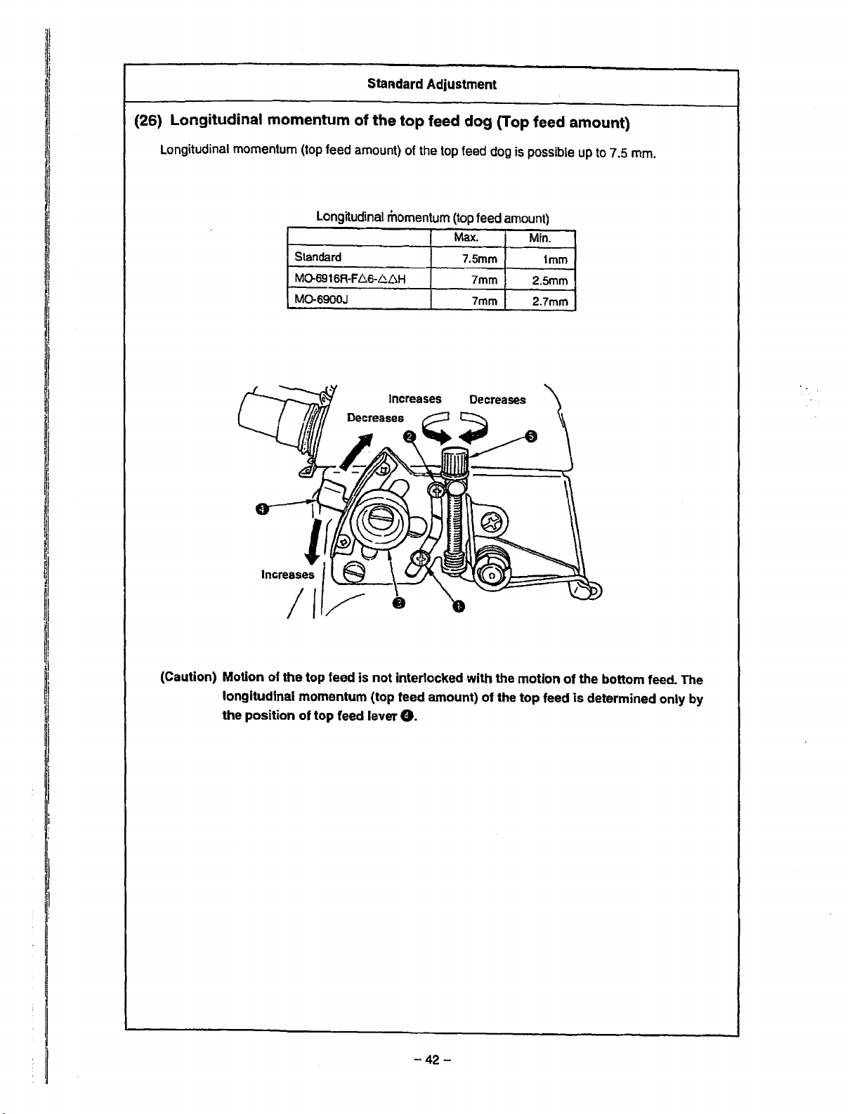
(26)
Longitudinal
momentum
StaAdard Adjustment
of
the
top
feed
dog
(Top feed amount)
Longitudinal momentum
(top
feed
Longitudinal
Standard
M0-6916R-F
MO-6900J
amount)
momentum
~6-6L\H
Increases
of
the
top
feed
(top
Max.
dog
feed
7.5mm
7mm
7mm
Decreases
is possible
amount)
Min.
1mm
2.5mm
2.7mm
up
to
7.5
mm.
(Caution) Motion of
longitudinal momentum (top feed amount)
the
position
the
top feed is
of
top
not
feed lever
interlocked with the motion
of
the
top
feed
8.
-42-
of
the bottom feed. The
is
determined only by

Adjustment Procedures
1)
Changing the longitudinal
of
the top feed
G)
Loosen top feed lock nut
direction of the arrow mark to adjust the stroke.
dog
® When top feed fine adjustment screw 8
to slightly move top feed lever
2) Changing the maximum momentum
CD
Loosen setscrew O
and lower the stopper to increase the maximum momentum
and raise the stopper to decrease
in
momentum
Ct
and move top feed lever 8
(top feed amount)
in
the
Is
used, it Is possible
8.
the differe~tial feed adjustment stopper
it.
® After the adjustment, securely tighten setscrew 8 in the
differential adjustment stopper.
3)
Changing the minimum momentum
CD
Loosen setscrew • in the differential feed adjustment stopper
and lower the stopper to increase the minimum momentum
and
raise the stopper to decrease
it.
® After the adjustment, securely tighten setscrew 8 in the
differential adjustment stopper.
Results
o If the min. stroke
o
of
Improper Adjustment
is
decreased
mm
to 1
mounted inside the machine
head may come
among
therefore necessary to set the
min. stroke to 1 mm or more.
If
to 2.5 mm
stitch machines of 50H
type, the
come
looper
necessary to set the min. stroke
to
aforementioned
machines.
or less, the components
In
contact with
one
another.
the min. stroke is decreased
or
less
for
safety
or
top
feed
dog
in
contact with the upper
holder. It is therefore
2.5
mm
or
more
for
types
It
is
60H
may
the
of
-43-

Standard Adjustment
(27) Vertical momentum of the top feed dog
Relation between the position
of
vertical adjustment pin
and the vertical momentum
Vertical
Adjusting position
Striking
to
end of groove.
Marker
line position A
Marker line position B 6.5mm
1
to
1.5
mm
on
1his
side
from
striking
to
end
of
groove
* In
case
of adjusting
adjustment screw
the
8,
check that the pin does
momentum
3.5mm
5.0mm
8.5mm
position
of
not come in contact with upper knife support,
needle clamp, etc. Then securely tighten vertical
adjustment screw
8.
0
Application
Light
weight
materia!
Light·
to
medium·weight
Medium·
Extra heavy·weight materials
to
heavy.weight materials
vertical
Striking
materials
to
top
end
of groove
Marker line
position
Marker line position e
1
to
1.5
striking
mm
to
A
top
on
this
end
side
of
groove
from
Vertical adjustment arm
Assembling position
Move
exhaust
to
the
right
(Screw
: left
of
locus cut
slot
side
of
ove
crew : right
mm
support
slot)
__..
locus
base
and exhaust slot support
8
cut
base 8 to
side
of
the left.
slot)
Check that the locus cut screw is adjusted to the position (almost the center) of the aforementioned
dimension of the vertical adjustment arm support section.
-44-

Adjustment Procedures
Results
of
Improper Adjustment
1) Remove the top cover, locus cut base 8 and exhaust slot
support&.
nut
2} Loosen vertical adjustment
pin
8 to a proper position.
3} After the adjustment. stop locus cut base
support 8 at the position
O and move vertical adjustment
8 and exhaust slot
as
shown in the figure.
o When the position of vertical
adjustment pin 8 is changed,
the vertical momentum of top
feed dog changes.
o When vertical adjustment
is moved toward the top end of
vertical adjustment arm,
momentum is decreased and
when it is moved to
momentum is increased.
o When the vertical momentum is
increased, jumping occurs and
noise may occur at high speed.
In this case, tighten the upper
the
pin
the
root,
f)
-45-
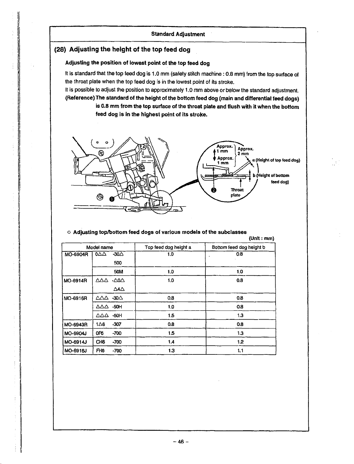
Standard Adjustment
(28) Adjusting
Adjusting
It is standard that the top
the throat plate when the top feed dog
It
is possible
the
height of the top feed dog
the
position
to
adjust the position to approximately 1.0 mm above
of
lowest point
feed
dog is 1.0 mm (safety stitch machine : 0.8 mm) from the top surface of
of
the
top
feed
is
in the lowest point of its stroke.
dog
or
below the standard adjustment.
(Reference) The standard of the height of the bottom feed dog (main and differential feed dogs)
is 0.8 mm from
feed dog
the
top surface
is
in
the highest point
of
the throat plate and flush with
of
its stroke.
it
when the bottom
o
Adjusting
M0-6904R
MO-6914A
MO-6916A
MO-6943A
MO-6904J
MO-6914J
M0-6916.J
top/bottom feed dogs
Model name
0~
-306
500
SOM
1.:.b.b.,.
-,Mb...
M.6.
~~
-301~
6.6.D.
-SOH
b.6.6
-60H
166
-'J07
OF6
-700
CHS
-700
FH6
-700
of
various models
Top feed dog height a
1.0
1.0
1.0
0.8
1.0
1.5
0.8
1.5 1.3
1.4
1.3
of
the subclasses
Bottom feed dog height b
0.8
1.0
0.8
0.8
0.8
1.3
0.8
12
1.1
(Unit:
mm)
-46-
. I

Adjustment Procedures
Results of Improper Adjustment
r
.I
1) Loosen setscrew 8
in
the
top
feed dog and move top feed dog
8 up or down to adjust the height.
(Caution) 1. Perform the adjustment
standard top feed pressure is applied.
2.
Top
feed dog 8 is removed and personal
injuries
screwdriver and securely fix setscrew 8 in
the top
may
occur. Use a
feed dog.
in
the state that the
rather
large-sized
o When top feed
higher than
Sewing
materials is possible.
However, a clearance
provided
bottom feed dogs, and partial
shirring performance of lightweight materials or feed force
is decreased.
o
When
top
lower
than
Partial shirring performance
feed
force
dog
the
standard
of
heavy-weight
between
feed
dog
the
standard
is
increased.
Is installed
top and
is
installed
However, when overlapping
amount of top and bottom feed
dogs is excessively increased,
feed
dog
defect is apt
Besides, sound may become
higher.
o
In
case
of
sewing
to
heavy-weight
materials
It
is
possible to sew even when
vertical stroke is increased.
Refer
momentum
to
a(27)
of the top feed
Vertical
I
is
or
occur.
dog~.
-47-

Standard Adjustment
(29) Locus cut of the top feed dog
Locus
cut
dog
actually
top
feed
By
this
can
be obtained
weight
is
less
The
locus
mechanism
feeds
dog
motion.
mechanism,
ones
such
for
light-weight materials.
cut
mechanism
makes
longer the
cloth
by
leveling
the
effect of prevention
when
sewing materials thicker than medium-
as
knitted
does
fabrics
not
the
or
the
work
section
lower
like
in
where
side
of
the
of
irregular stitches
although
the
state
the
of
delivery.
the
locus
effect
feed
of
Locus of
Cloth
Set
feed
the
dog
standard
(30) Adjusting
Range
of
effective feed
of
cut
amount
the
longitudinal position
to approximately
A
0.5
of
mm.
the
top
feed dog
0
Clearance between top
top
feed
strokeO
Clearance between
feed
dog
Model name
MO
-6916R-F66
MO
-6943R
All
models of
excludilg
is
maximum,
8 travels
aforementioned
to
-50H
F.66
60H
-1
D6
-307
M0-6900R,
top
the
feed
feed
front
and
J
models
dog 8
and
is
as
shown
dog 8 and
end
= dimension A
the groove
in
the
list
of
presser
below.
groove of presser 8
(Unit:
dimension A
0.8
1.0
0.5
-48-
mm)
8,
when
when
top
Top
feed
arm
c

Adjustment Procedures
Results
of
Improper Adjustment
1) Remove the top cover.
2)
Turn the handwheel to bring the top feed dog
point of its stroke.
3) Loosen locus cut screw nut O and tighten locus cut screw
Then the top feed dog rises.
4)
When a proper cut amount
nut 8 so that locus cut screw 8 does not turn.
5) Loosen the setscrew in the top
dog to the position where
(Caution}
1.
When
the
machine
2.
When
a forced load
Use
1
mm.
is
obtained, tighten locus cut screw
feed
it
bites cloth.
using
the
machine with locus cut, use
at
a speed
the
cut
amount
Is
applied
the
machine with locus
dog and lower the top feed
of
exceeds 1
to
5,500 rpm
mm
to
the
mechanism.
cut
of
the Io·west
or
less.
or
more,
less than
9.
o
The
lifted
amount
lowest point in the step 3) is the
cut
amount. In this state,
clearance
bottom teeth
large as the cut portion and feed
force is decreased. Be sure to
adjust the biting amount of cloth
by lowering the top feed dog in
the step 5).
between
is
increased
from
top
the
the
and
as
l
I
ii
!
!1
i
;I
!!
I
I
I
1) Remove the
feed arm C
2) The tightening torqueses of clamping screw O
arm C after the adjustment is
(Caution) 1.
top
cover and loosen clamping screw O in the top
to
adjust the position.
BON.
Do
not
completely loosen clamping
0 in
the
top feed
2.
If
clamping screw O in the
loosened and has moved to
completely
and
tighten
naturally.
arm
C.
top
the
loosen
it
it,
turn
the
at the position where
in
the top feed
screw
feed arm C is
right
or
left,
handwheel
it
comes
o When dimension A
top feed dog O comes in contact
with
presser
occurs.
Besides,
excessively improper, the top
feed dog may come in contact
with
frame.
performing the adjustment.
the
other
components in the
Be
is
improper,
0,
and
dimension
careful
noise
is
when
!
I
I
I
-49
I
·-
I
ij
i

Standard Adjustment
(31) Adjusting
Clearance between top feed
a =
a·
(0.2
b = b' (0.2 mm)
the
mm)
lateral position
dog
8 and presser • is 0.2 mm.
_,..,._......,-
•
--
___
-,1.
______________
of
the
top
~-;;=;=;::===R==t==t=
~~~--
feed dog
l=-===~==I=
t===::i1::::t===t::b'
a
a'
b
Top
feed arm C
(Caution) 1. Adjust the position only when there ls a concrete problem that presser 8 and
feed dog 8 come
clearances are excessively different from each other and trouble occurs, etc.
2. When the adjustment value ls improper, there
the components occurs, a bad influence Is given to the durability
machine
of
or
the
space. So, be careful.
in
contact
the like since the
with
each
other
and noise occurs, the
is
the possibility that contact among
top
feed mechanism is strictly assembled because
left
of
the sewing
and
top
right
-50
-

Adjustment Procedures
Ii
Results of Improper Adjustment
1)
Loosen the setscrew in the feed bar guide B.
Refer to "(33) Adjusting the feed bar guides A and
2) Remove the top cover and loosen setscrew O
arm
C.
Refer to (30) Adjusting the longitudinal position of the top feed
dog.
3) Loosen the setscrews in thrust collars 8 located
sides of the horizontal shaft and move the set of horizontal
shaft, top feed
position in the thrust direction (direction you desire to adjust
the position). Then fix two thrust collars
(Reference) When loosening the setscrews in thrust collars
8,
do not simultaneously loosen the two setscrews. First,
loosen thrust collar 8 on the side
fix
it
at the predetermined position. In the state
it
in the direction, check that contact at the lateral position
or at the top feed mechanism does not occur. After the
checking, move and
aforementioned procedure can perform good adjustment.
4)
Tighten
aforementioned order and perform the adjustment.
the
respective
bar
and top feed dog to
.fix
the remaining thrust collar
setscrews
the
Oat
of
moving direction and
by
B".
in
the top feed
on
the both
predetermined
the position.
of
pressing
e.
The
reversing
the
o
Excessive
directions of cloth base side and
handwheel side produces
contact of top feed bar with the
respective sections of top feed
mechanism.
(Fully
torque, engagement,
the time of adjustment.)
check
move
the
in
change
or
noise at
both
the
of
I
ll
j
I
~
'I
~
I
~
11
r
-51
-

Standard Adjustment
(32) Position of the motion
Adjusting the position of
Loosen
the
o Intermediate constant (standard)
the setscrew in horizontal ann A O
position of the motion
the
of
motion
the
o Intermediate constant
When the pitch
of
the
top
o Rear constant
When
the pitch of
position of the
o Front constant
When
the
pitch
position of the top feed
top
of
the
feed
the
top
top
feed
dog
feed
dog
of
the top feed dog
of
the
top
and
top
feed dog.
o Rear constant
feed
dog
is
increased,
dog
is increased, locus extends
is
constant.
dog
is
increased, locus extends
is
constant.
feed
move
dog
the
position
the
top feed dog extends
to
to
of
horizontal
o Front
the front while the
the
rear while
arm
constant
to
the front
the
A O
to
change
and
rear.
most
retarded
most advanced
i
I!
Position of the motion
of the
top
feed dog
changes
the installing angle
of
arm
by
changing
f!f
horizontal
A 8 and horizontal
armB9.
--52
Horizontal
should
-
not
feed
~
sway
link 8
to
the
right or left.

Adjustment Procedures
Results
of
Improper Adjustment
o Intermediate constant
1) Make horizontal arm
turn
the handwheel
where it is desired to
2)
At the position, tighten horizontal
the
top feed dog does not move even when the top
is
moved.
3) Loosen horizontal arm C 8 at the position where the top feed
dog
does not come
of the presser even when the pitch of the top feed dog is
maximized. Then adjust the position of the horizontal shaft.
AO
in
the state of temporary tightening,
and
adjust the top feed dog
be
constant.
arm
in
contact with
the
to
the position
A 8 at the position where
feed
lever
front or
rear
of
the
groove
o Rear constant
1) Make horizontal arm A O
turn the handwheel and adjust the top feed dog to the most
retarded position.
2) At the position, tighten horizontal
the top feed
is
moved.
3) Loosen horizontal arm C O
dog does not
of the presser even when the pitch of the top feed dog is
maximized. Then adjust the position of the horizontal shaft.
dog
does not move even when the top
come
o Front constant
1)
Make horizontal arm A O
turn the handwheel and adjust the top feed dog to the most
advanced position.
2)
At
the position, tighten horizontal arm A O at the position where
the top feed
is
moved.
3)
Loosen horizontal
dog
does not come
of the presser even when the pitch
maximized. Then adjust the position of the horizontal shaft.
(Caution)
dog
does not move even when the top
arm
1.
Never loosen
keeps the .thrust
2.
Set horizontal ann CO
horizontal feed link 8 lightly moves without
play.
3.
Provide a clearance of 0.5
between
the presser when the
in
the state of temporary tightening,
arm
A O
at
the position where
feed
at
the position where the top feed
in
contact with the front or rear of the groove
in
the state of temporary tightening,
feed
C 8 at the position where the
in
contact
the
with
the front or rear
of
the top feed dog is
horizontal
of
the horizontal drive shaft.
top
feed
arm
to
the position where
dog
and
pitch
is
top
of
the
groove
B8
since
mm
or more
the groove
maximized.
lever
lever
feed
of
o At the time of rear constant, the
lowest point of the
is
apt
to
be
lowered
increasing the top feed stroke
(clearance between top feed
and
bottom
increased)
for partial shirring. Use the top
feed dog with
constant or front constant.
and
feed
there
o When the top feed dog is set to
front constant, biting of cloth at
the start of sewing
However, a few loading is apt to
~cur
at the overlapped section
of
knit tab ric
it
o If the play between horizontal
arm
C 8
and
horizontal feed link
0
is
large, the return of the top
feed
adjusting lever
and a forcible load
the components.
top
feed dog
when
dogs
is
is
no
effect
Intermediate
Is
improved.
is
worsened
is
applied to
/
11
l
f
1·
11
I·.
I
-53-

I
Standard Adjustment
(32) Position of the motion of the top feed dog
1.
The
position
intermediate constant for other models at the time of delivery so that the best locus suitable to the
purpose of use can
2.
Intermediate constant position at the time of delivery
The
position
to the position where the top feed dog does not move even when the top feed lever is moved at the
position where the timing is advanced
of
motion is adjusted to rear constant for 50H and 60H series and MO-6900J, and
be
obtained.
of
motion of the top feed dog other than that of 50H, 60H and MO-6900J is adjusted
by
19· from the upper dead point
Upper
dead
point
of
needle.
of needle
to
11
,j
I
I'
(33) Adjusting the feed bar guides A and B
I
I
~
11
·1
I
I
11
~
11
I
I
lj
I!
I
When the play
removed by adjusting the feed bar guides A and
of
the
top
feed dog in the lateral direction is excessively increased, the play can be
Hole on this side
Oil
Upper
ofneedle
B.
pan
dead
side
point
II
1,
I
i
I
I
1!
-54
-

Adjustment
Procedures
Results
of
Improper
Adjustment
o Standard of the position where timing is advanced
the upper dead point of the needle
1) Timing is advanced by approximately
point of the needle at the position where the hole in the periphery
of the handwheen faces just under.
21
• from the upper dead
by
19·from
1)
Remove top cover, locus cut base, exhaust slot support, and
adjusting arm spring.
2) Loosen top presser adjusting screw
screw nut
in the lateral direction of top feed dog
3)
Remove the needle thread tank, loosen setscrew O in the feed
bar guide B and temporarily tighten feed bar guide B 8 so that
top feed bar 8 is put between feed bar guides B 8 and A C,.
4) Move top feed dog 8 up or down and adjust so that top feed
dog 8 comes down by its weight and that the play in the lateral
direction of top feed dog 8 is kept down to a minimum.
5)
When
does not come down by its weight even after adjusting feed
bar guide B 81 loosen setscrew 8 in the feed bar guide A and
adjust feed bar guide A
the lateral position of top feed bar C,
feed dog O drops naturally when moving it up
C,,
release top presser pressure, and check the play
jar
is produced at top feed dog • and the top feed dog
C,
at the same time. At this time, adjust
0,
top presser adjusting
8.
to
the position where top
or
down several
times.
6)
Securely tighten the respective setscrews and check that there
is
neither play
7) Return adjusting
base and top cover to their home places.
Refer
to
(Caution)
When
and top feed barC,, jumping
Adjust
down
by
nor
jar.
arm
spring, exhaust slot support, locus cut
"(27) Vertical stroke of the top feed dog".
jar
occurs
between
the
top
feed
dog
its
weight as mentioned above.
feed
of
top feed dog 8
to
such
an
bar
guide
extent
will
A 8
and
be caused.
that
It
B
8,
comes
o
When
the
play
in
the
direction
occurs, the top feed dog comes
in contact with the presser and
noise occurs
is apt to be put
o
On
occurs between fedd bar guides
A
Cl
0,
phenomenon of top feed dog
will be caused.
of
top
feed
dog
or
feed dog defect
on
cloth.
the contrary, when torque
and B
8,
and top feed bar
inducement of the jumping
lateral
0
f)
-55
-

Standard
Adjustment
(34) Adjusting
1.
Standard
tightened, sound becomes quiet and
lower pressure.
Besides, when using the top
amount of the
2.
Dimensions listed
vertical amount of top
Accordingly, when using the machine
decreasing the sewing speed, use it with rather large value (top feed dog pressure
dimensions A
the
top feed dog pressure
<Standard height
Dimension A
MO-6900R
MO-6900J
is
the position where the top feed dog stops jumping and,
is
feed
dog
making low the top
top
feed dog or decrease the sewing speed.
in
the list are slightly increased values that
feed
dog and sewing speed are
in
the list.
24to25mm
20.5
to
21.5mm
20.5
to
21.5mm
stabilized when gradually tightening the screw
feed
dog
can
in
the most strict combination
by
decreasing the vertical amount of the top feed dog or
of
top presser adjusting screw>
Vertical
amount
top
feed
Less
than
6.Sto8.5mm
8.5mm
when
pressure, decrease the vertical
be guaranteed
of
Max.
dog
6.5mm
sewing
7,000rpm
7,000rpm
6,000rpm
further the screw
even
in
is
from
when
the list.
low)
speed
is
the
the
than
(35) Lifting amount
The height
the lowest point of
of
the top feed
of
the top feed dog (when operating the pedal)
dog
the
needle bar and
from the
top
the
surface
top
feed
of
the
dog goes
In
case
throat plate when
up
to
the highest point is 9 ± 0.5
of MO-6900J, the height
the
pedal is depressed at
is
10.5 ±
0.5
mm.
mm.
-56
-

Adjustment Procedures
'I
I
Results of Improper Adjustment
Loosen top presser adjusting screw nut
presser adjusting screw
and feed force
top presser adjusting screw nut
(Caution) When the top feed dog jumps and noise becomes
large during using the sewing machine, tighten top presser
adjusting screw 8 until noise becomes small. When the
machine
large, a forcible load is applied to other section.
careful.
is
is used for many hours while noise is excessively
8.
the top feed dog pressure is increased
increased. After the adjustment, be sure to tighten
8.
0.
when tightening top
So,
be
o When top feed dog pressure is
excessively low
Top
feed
dog
jumps
and
noise
becomes large.
Feed force is decreased.
o When top feed dog pressure is
excessively high
Feed dog defect is put on some
materials.
Unnecessary load is applied to
the
sewing
sewing
the worse by it.
Noise level is increased.
machine
machine is influenced for
and
the
I
I
I
I
I
II
11
1)
Loosen lifter B stopper nut O and
to adjust the lifting amount.
2)
After the adjustment, tighten lifter B stopper nut O.
<Checking after adjustment>
Play
between the top end
presser lifting
feed
dog is brought to the lowest point (needle bar is at highest
point).
(Top end
arm 8 by 0.5
arm
8 should
of
the screw should be separated from presser lifting
to
1 mm when pulling the lifter B with finger.)
turn
litter 8 stopper screw 8
of
lifter B stopper screw 8 and
be
0.5 to 1 mm when
the
top
o When the lifting
top feed dog is excessively
contact occurs between vertical
shaft
and
occurs
sewing machine.
when
lifter
amount
B,
and
operating
of the
high,
noise
the
o When the lifting amount of the
top feed dog is excessively low,
when entering cloth
of
sewing
materials, cloth
to
be
entered
dog.
at
the start
heavy-weight
may
be
not able
at
the
top
feed
11
11
I
II
II
11
Ii
I
I
- 57
--

Standard Adjustment
(36) Height of
Height of the presser from
the
presser
the
top surface
(pedal
operation)
of
the
throat
MO
MO -6914R
MO -6916R
MO -6943R
MO -6914R
MO -6914R
Whole
plate
-6904R
when
the presser goes
Model
-0.6.4
0.6.6
064
-8.6.4 -307
8.6.6
-
-064
0.66
FF6 -300
F.6.6
F.6.6
-106 -307
-866
-.6..6..6.-4.6.H
M0-6900J
-300
-300
-500
-307
-300
-300
-SOH
-60H
-337
uo
to the
highest
Height
of
presser A (Max.)
5.5±0.2
5.5±0.2
5.5±0.2
5±02
5±0.2
(Unit:
7_~
6.5_~
7_~
6.5_~
6.5_~
8_~
point
mm)
·-
Level
(Caution) When height A of the presser is adjusted
connection with it,
changed. Check
the
presser referring
the
adjustment value
the
lifting amount
to
"(35) Lifting amount
of
the
of
top
pedal)"
-58-
•
at
the time of operating the pedal, in
the
lifting amount of the top feed dog is
feed
dog
after adjusting the height
of
the
top
feed dog (when operating the
of

Adjustment Procedures
1}
In
the state that the presser pressure is applied, loosen presser
tu
ming lock nut O and adjust the height with presser lifter turning
setscrew 8
operating the presser lifting pedal.
At
this time, check that there
upper looper, needle clamp, top feed dog, etc.
(Caution) Adjust
between
pedal
is
with
presser lifter turning setscrew 8
so
that the height in the list is obtained when
the
height
presser arm O
pressed
and
so
and
presser
is
no contact of the presser with
that
there
is
a slight clearance
presser
lifting
arm
stopper 8 when
arm O comes
and
stops.
in
contact
Results of Improper Adjustment
o When the height of the presser
is excessively low, entering
taking
hard.
o When the height of the presser
is excessively high, there is the
possibility
comes in
looper, needle clamp, etc.
out of
that
contact
cloth
the
becomes
with
or
presser
upper
o Adjust the height
thrust arm 8
1) Removing the thrust play of the presser shaft, temporarily
tighten thrust arm clamping screw
Lower the presser by 1
presser arm
2} Next,
3)
in
the state of the aforementioned 1 ), fix presser lifter
arm
t)
with thrust arm clamping screw 8 so that presser lifter
arm
t)
Is
level and there is no clearance at section A.
Adjust
aforementioned lifter B stopper screw 8 and nut
the height of the presser with presser lifter turning setscrew 8
and nut
the
C,
by
the procedure below even when presser
is
removed.
to
O.
lifting
amount
so that the height
8.
3 mm from the throat plate with
of
the top
in
the list is obtained.
feed
dog
0.
and adjust
with the
I
I
I
,I
,.:111
!I
I
-
59
-

Standard Adjustment
(37) Lifting amount
It is the standard that the height from the top surface of the throat plate is 9 ± 0.5 mm when presser
lifting lev
highest point. MO-6900J : 10.5 ± 0.5
er
0 is pressed at the lowest point
of
the top feed dog (when
mm
the
presser lifting lever is operated)
of
the needle bar and top feed dog O goes up to the
-
60
-

Adjustment Procedures
Results of Improper Adjustment
1) Remove cloth base side cover
2)
Bring the needle bar to the lowest point of its stroke and keep
top feed dog 8 at the height of 9 ± 0.5 mm (M0-6900J : 10.5 ±
0.5 mm) from the top surface of the throat plate.
(Insert
the
s~cer
between the throat plate and top feed dog
3)
Loosen clamping screw 8 of lifter A
4) Press presser lifting lever O until
it.
In
this state, turn lifter A O and strike the pin section to the
eaves section of top feed square block C,. Then tighten
clamping screw 8 of lifter A
(Caution) In the state that presser lifting lever
check that
ther_e
is a clearance between the pin
8 and the eaves section of top feed square block
5)
Return top feed cover G and cloth base side cover 8 to their
home positions.
f)
and top feed cover
8.
it
will go no further and tum
0.
8.
f)
is returned,
of
0.
0.)
lifter A
o When the lifting amount of top
feed dog O
contact of top feed square block
is
excessively high,
8 with the pin section of liter A
0
occurs
operation
wrong with the machine.
o When the lifting amount of top
feed dog 8 is excessively low,
cloth
or
hard to be removed at the thick
section
section
at
the
time
and
something
the presser becomes
such
as
overlapped
or
the like.
of
is
I
ii
'I
'1
I
I
I
I
I
I
I
!
i
I
I
!
I
.I
I
I
I
I
1!
I
-
61
-

I I
i
I
i
I
(38)
Position
M0-6A04S
thread
guide
The
thread
hole
the
In
In
portion
the
position
noodle
~
and the hooked
take-up are
hole
in
-~--
of
the
(R)
Needle thread
B take-up
the
needle thread
of the needle thread
where
thread
guide
thread
guide
2/3
of
the
can
be
Standard
guides
Needle thread guide
of
The thread holo
and
take--up are In
and
Needlo thread take-up
2·need1e machine
z..,,eedle machine
the
hooked
=~~·
Adjustment
the looper thread take-ups
M0-6M4S(R)
In
the
needle thread
portion
of
the
position
nees:ead:lde
~
lever
of
the needle thread
where 2/3
guide
of
the
can
be
M0-6616S
Needlo thread take-
up
guide
hooked
are
In
the
the
of
hole
in
the
needle
of
the
position
chalnstitch
The thread
and
the
take·up
hole
om=~
The thread hole In the double-chalnstltch
needle thread
portion
in
the needle thread
(R}
e
Needle
double·
machine
portion
)
machine
in
the
needle thread guide
ol
the
position
thread
guide
and
needle thread
where
the
guide
can be
needle thread
where 2/3
guide
the
tak~up
entire
observed.
thread
of
tho
can
hooked
are
hole
be
In
(Caution) The needle thread take-up shall be positioned at the lower dead point.
Symbol
A
D
C
D
E
F
G
H
I
J
K
L
M
N
0
p
Upper looper thread
guide {middle)
F
H
Looper
thread
take-up (left)
MO-6.::,04S
General
thread
15.8
3.4
(R}
(Standard)
woolly
thread
-
-
-
22
65
17.5
43.5
26.5
38
15
6.5
29
27
11
-
-
•-
-
-
-
41
-
-
-
21
...
.
J
M0-6.:..14S
(Standard)
General
thread thread
-
-
.
-
- -
-
-
-
38
12 15
10
-
23
-
. .
Upper looper
(R)
Woolly
-
-
.
-
-
-
-
-
-
-
-
-
throad
Upper
I
MO-6.:.165
(Standard)
General
thread
·-
1.8
21.5
30.5
-
-
-
- -
-
34
12
6.5
27.5
20
-
16
guide (upper)
looper thread guldo (right}
Lower
thread guide
Lower
looper
thread take.up
-
-
-
-
M0-6..::.16S (R)
(50H,
OOH)
General
thread
-
2.6
2.3
24.5
(R)
Woolly
thread
- -
-
-
-
36
15 12
-
- -
--
-
·-
-
-
-
-
34
~-
19
-
12.B
looper
General
thread
40.5
M~,:05S(R)
(Hemming)
Woolly
thread
-
3.4
-
-
-
--
24
38
12
24
29
24
12
-
-
-
-
-
-
-
42
-
34
-
-
-
(Unit:
mm)
M0-6~045
General
-
(Soft
(R}
chain)
thread
13.5
2.1
-
-
-
--
-
43.5
26.5
43.5
14
-
26.5
19
9.5
-
-62-

Adjustment Proc~dures
Results of Improper Adjustment
I I
1) Perform the adjustment by the setscrews. Position of the needle
thread guide O and needle thread take
important decisive factor· when making soft chains since the
needle thread take-up amount is increased in this case. So,
carefully position these parts.
Large
0
2)
Set distance I a little smaller when
using synthetic thread
which tends to form stitches swelling
out of the cloth edge.
A smaller I is effective for preventing
stitcli skipping.
3) Distance J
and lower looper threads.
Set this distance larger for wooly thread, and set it smaller for
thin thread which is likely to cause stitch skipping.
4)
It is desirable to set distance K l~rger for stretchy threads such
as wooly thread.
5) Set distance L a little larger when making blind hemming soft
chain stitches.
6) Set distance N a little smaller for blind hemming
chain stitches.
7) Set distance O larger if stitch skipping occurs due to looper
thread slack.
Set
stitches when wooly thread
·is
it
smaller for better appearance and touch of produced
Lower
looper
Upper
~Small
---~
or
the like
related to the vertical knotting point of the upper
Is
used.
Needl~hread
looper
@
up
8 lever is a very
take-up
Upper
amount
I
or
looper
slack
Swell
making soft
out
o Distance@
When
tightness
stitches will be obtained.
When set larger, loose needle
thread stitches
o Distance
influence on stitch formation,
however,
these
contact
parts.
o DistanceJ
When set larger, the amount of
the upper looper thread will be
increased.
When set smaller, the amount
of the upper looper thread will
be decreased.
o Distance K
When set larger, the amount of
the upper looper thread will be
increased.
When set smaller, the amount
of the upper looper thread will
be decreased.
o
Distancel
When set larger, the amount
the upper looper thread will be
increased.
When set smaller, the amount
of the upper looper thread will
be decreased.
o Distance N
When set larger, the amount of
the upper looper threa~ will be
increased.
When set smaller, the amount
of the upper looper thread will
be decreased. ·
o Distance I
When set larger, the amount of
the
threads will be increased.
When set smaller, the amount
of
threads
o DistanceO
When set larger. the amount of
the
threads will be decreased.
When set smaller, the amount
of the upper and lower looper
threads
set
smaller,
of
needle
will
E,
F and H exert least
improper
distances
between
upper
and
the upper and lower looper
will
be decreased.
upper
and
will
be increased.
result.
setting
will
the
lower
lower
better
thread
cause
moving
looper
looper
I
of
of
-63-
ll
1,

Standard Adjustment
(39) Adjusting soft chain making mechanism
1) Replacing the parts
8 Needle thread presser
with
those exclusively designed for making soft chains
p1ate
C ....... 12112504
8 Driving cam .................................... 12112603
8 Needle thread presser spring B .•... 12112702
· 8 Throat plate .................................... {only
0D4·3O0 ......................................... R4200J6OO0A
2)
Adjustment value
CD
Needle thread guide and needle thread take-up lever
Adjust
the
needle thread guide
is
In
the lowest dead point
3,l
fo35/
to
increase the
of
its stroke.
Needle thread takeup amount when the
needle
bar
lowest dead point
·
mrn
for
1-needle
overlock machine)
needle
is
in its
thread
feeding
2.5
f)
amount
f03,n,n
when
the
needle
Needle thread take-
up
amount
needle
/ lowest
bar
dead
when
is
in
point
bar
the
its
I
I
ii
1·
.I
(04 1-needle overlock machine)
® Adjust the rising amount
Adjust the rising amount
driving cam 8 to the right and left
Rising amount : 0.6 to 1 mm {max.)
of
needle thread presser plate
of
needle thread presser plate C 8
•
within
the slot.
-64-
(16 Safely stitch machine)
C.
to
0.6 to 1 mm {max.)
by
moving
~

3)
Important points in adjustment
CD
Increase the thread take-up amount of the needle thread take-up lever.
Refer to
the
adjustment values related to the needle thread guide and needle thread take-up lever.
® Reduce the feed of the looper threads. (Mainly lower looper thread)
Set J,
K,
Land
M for
the
soft chain distances.
Fine adjustment of J and M is required to produce even stitches.
(3)
Adjsut the thread tension while checking the appearance
1)
Minimize the needle thread tension
as
far
as
satisfactory tightness of needle thread stitches
obtained.
2) Increase the upper looper thread tension
as
much as possible.
© If the chain:.off thread does not stretch satisfactorily, and
following.
1) Increase the upper looper thread tension.
2)
Further increase distances J
3) Further increase the upper looper thread tension.
4)
Increase the lower looper thread tension to a maximum
thread stitches is maintained.
5) Increase the thread take-up amount. If the needle thread
thread tension.
@ Fine adjustment for producing stitches with better appearance
1) If the knotting point varies at high or low sewing speed, slightly reduce
lower looper thread tension.
2) If a
knot
is
made
at
a high point, increase J and
3) If the needle thread
is
thread tension.
®
Pay
attention
1) Minimize the needle thread tension as far as satisfactory tightness of needle thread stitches is
to
the following
obtained.
2) The knot of upper
3) Minimize
4) For a safety stitch machine, adjust the soft chain making mechanism
thread
Upper
looper
thread
guide (middle)
the
is
produced during double-chain stitching and overlocking.
and
lower looper thread tension as far
Upper looper
G K
17
5
and
K.
I.
likely to break, decrease the thread take-up amount
lower looper threads should be made near the upper edge of a material.
as
even stitches are maintained.
thread
guide
(upper)
14 Upper looper thread guide (right)
and
touch of the stitches produced.
if
it
is
not satisfied, proceed with the
as
far as good tightness
is
poorly tensed, increase the needle
and
touch
L,
and increase the
and
lower the needle
so
that uniform chain-off
of
needle
is
Soft chain stitches
Standard stitches
~
Lower
When the chain-off
thread is pulled.
When the chain-off
thread
is
pulled.
Lower looper
thread
looper thread
c:::>
c:::>
-65-
guide
The value given
is
the
safety stitch machine. (Unit : mm)
tako-up
~saess:
~lftf'li"trw'll"'I
OiO\tmll!U~rna:
Looper
loosened and stretch well
//
:ti
in
( ) parentheses
adjustment
The looper thread loosens
value
for
the
thread should not be

Standard
Adjustment
(40) Position
of
the
M0-6904G (J)
The thread hole
guide and the hooked portion
needle
position where 1/2 to
in
the needle thread guide cannot be
observed.
thread
in
the needle thread
take-up
the
thread guides and the looper thread take-ups
of
the
are
in
the
entire hole
M0-6914G (J)
Needle thread take-up
2-needle machine
Needle thread
guide
of
2-needle
machine
The
thread
thread
guide
portion
of
up are In the
the
entire hole in
guide"~
of
hole
in
the
and
the needle thread take-
position
the
needle
the
hooked
where 1/2
needle thread
The
thread
portion
up
to
the entire hole In the needle thread
guide
M0-691
Needle
thread
chainstitch machine
thread
hole
guide
of
the
are
in
the position where
cannot
be observed.
SG
take-up
in
and
needle
of
MO-6900G(J}
(J)
of
double·
the
needle
the
hooked
thread
take-
1./2
to
(Caution)
M0-6903G
'1-sia""
The
needle
14,8mm
Needle
thread
take-up
thread
M0-6905G
take-up shall
be
positioned
Needle
thread
take-up
st\
at
the
~
lower
dead
point.
-66-

MO-6904G (J), 6914G (J), 6916G (J)
M0-6903G
(Caution) The
and the looper thread take-up (left) shall
be positioned
of
u_pper
the
MO-6905G
looper thread-take.up (right)
at
the extreme right
upper
looper.
point
lll
Ii
'I
i
l
I
·,l
I
I
i
11
Ii
I
'-I'
C
Position M0-6904G(J)-OF6-700 MQ-6914G(J)·CH6-700
A
B
C
D
E
F
G
H
I
J
K 17
70
22
48
18
43
22
11
27
23
18
....
...
-
-
...
-
,._
-
-
-
-
M0-6916G(J)-F
-
-
-
-
-
-
-
-
-
-
-
~6-
700
M0-6905G-OM6-7
65
20
46
-
22
18
16
26
20
10
-
~O
(Unit:
mm)
M0-6903G-ON6-3D1
-
-
52
-
-
-
13
31
-
-
27
-67-

4.
ADDITIONAL
(1) Thread tension
INFORMATION
AND
PRECAUTIONS
1) Strength of tension
Pan
No.
11550100
11550209
13137807
13138508
13138805
B3121804000
Color
Purple
Green
Yellow
2) Springs used
Mo
M0-6604S(R) series
MO-6P..05S
MO-M
MO·M
MO-6616S(R)-6L":.~·66.6.(4~6 or
MO-6.6.16S(R)-6fa'\-506
MO-6D.
MO-6643S(R) series
M0-66455
MO-6903G-ON6-3D 1 Blue
MO-6904G(J)·0F6M0-6905G-0M6-7
MO-6914G(J)-CH6· 700
MO-6916G(J)·FM-700
series
12S
series
14S(R) series
16S(R)-6D.ll.-60H Green
series
60
spring
Natural length Operating
(mm)
19.5mm
19.5
mm
Red
Blue
Gray
for
700
19.5mm
17.8mm
17.3mm
13.8mm
each model.
lower)
length
11.5
11.5mm
11.5
9.8mm
9.3mm
5.8mm
e
Needle
Red
Yellow
Red
Red
Red
Purple
Yellow
Purple Green
(mm)
mm
mm
thread
Yellow
Yellow
Red
Red
Red
-
Red
Weight required
spring to working length
8.92±0.49N (910 ± 50
6.27±0.49N (640 ± 50 g)
4.21±0.49N (430 ± 50
3.14±0.34N (320 ±
1.4 7±0.20N ( 150
1.47:t0.20N (150 ± 20
Double-chainstitch
needle·
thread
to
compress
:t
Upper
-
-
-
-
Yellow
Red
Green Blue
Yellow
Red
Red
-
-
-
Yellow
g}
g)
35
g)
20 g)
g)
looper Lower looper
thread
Yellow
Blue
Yellow Blue
Blue
Yellow Blue
Blue
Blue
thread
Yellow
Yellow
Yellow
Yellow
Yellow
-
-
Yellow
Yellow
Yellow
Yellow
Purple
Blue
-
Blue
Red
Red
Red
(2) Upper looper
Use a proper upper looper in accordance with the needle No. When ordering, refer to the Parts List. The
numbers shown in D frame in the table below are engraved markers.
parentheses are the kinds of the needles.
Parts Nos. with
Model
6604S(R)
6D.16S(R)
6~
14S(R) series ·1211
6903G-ON6·3D1
6904G(J)·OF6-700
6905G-OM6-7
6914G(J).CH66916G(J)·F66-700
an
asterisk• are factory·installed on the standard machine heads at the time of delivery.
Needle
{kind)
#11
No.
#14
Nos.engraved
series
series 1199
·11aa
1217
upper looper
[1Cl
C!L]
OD
on
#9
#14 #16 #18
#21
O[J
#16 (00x5)
#21
(0Ox5)
#24
(DCx1)
#18 (OOxS)
#21
(00x5)
-68
-
60
700
!1201481
!123835!
i
123837!
!123836!
!123835!
In
addition, the letters in ( )

(3) Center-to-center distance of the upper looper holder
The center-to-center distance of upper looper holder O.
MO-_ 6604S(R)
MOSS
MO-
6604S(R)
MO-
•
(Caution) * (asterisk) marks are exclusive for
to the MO-6900G(J). They are not
common
to
the MO-6000S(R)
series.
6612S
MO· 6612S
rvD-
6~14S(A)
MO-
6616S(R)
MO·
6616S{R)-
MO- 6943R
MO-
6M3S
MO-
6903G -ON6
MO-
6904G(J) -OF6
MO-
6905G
MO-
6914G(J) -CH6
MO-
6916G
Model
-t::.6.b
-Ab.6
-004
·OMS
(J)
OF6
-CE4
-D66
-~
~
BE4
0D6
-Mb.
-~
FH6
-
FF6
to
to
-666.
-A~O
OE4
-D.66
-61:..6
FFt::.-
-
4ti.H
.
50H
-40H
-1.:..li.O
4
61-1
561-l
-6D.7
-40H
-3D1
-700
700
7E0
-700
-700
(Unit:
Center-to-center
distance
38
39
38
39
39
38
39
39
39
•39
37.5
•39
37.5
37.5
mm)
C)
( 4) Caution in assembly
1) Application of sealant
G) Setscrew of the throat plate base (B) retainer 8 (JUKI seal)
Apply the sealant only to
® Bottom surface
Apply the sealant to the bottom
frame surface.
of
@ After assembling the front edge of the
sealant to the gap of the contact surface between the frame and the upper looper guide support O
(
Offlffl
section in the illustration).
Be
careful
sealant
Apply
the
right setscrew.
the upper looper guide support 8 (Three-bond 1104)
not
to
allow the
to
run
to
the
rear.
the
sealant
bottom surface.
to
surface
of
the upper looper guide support
upper
looper guide support e (Three-bond 1212), apply the
~1~~e
'y~
•7
c,_(~
8,
Apply
the
bottom surface.
Apply
only
to
_,
the right
setscrew
which contacts with the
sealant
to
the
-69-

©
®
Portion
Apply
(4
Oil
Apply
of
the
sealant to
pcs.)
shield plate assembly
the
sealant to
Vh"
//4'-"""~~-'L..ol::..L-<:'-441~...:.;._-
the
setscrews
the
the
of
the
oil
shield
(JUKI
inside of
dust-proof
case
setscrew O
seal)
the
oil shield plate
Apply
the
hatched parts.
rubber
the
sealant to
case
{1
8.
{JUKI
pc.)
and
seal)
the
dust-proof rubber case 8 setscrews
.::·.:
® Portion
Apply
the
top
Apply
Apply the sealant
plate and the
Be
careful
of
the sealant to
oil shield rubber support plate ,
surface of
the
sealant
top surface
that
the sealant should not overflow on
the
feed
mechanism cover (Three-bond 1212)
the
feed bar presser.
to
the
of
the oil
shield plate.
to
the
oil
top
surface
the side
of
Inside contact surface
the
rear face of the
the
top
shield rubber support
of
the oil shield case.
the oil shield
rubber.
feed
mechanism cover, the
surface of
the
Feed
cover (rear
top
oil shield case,
mechanism
face)
Ughtly
face
of
and the top surface
presser.
surface
apply the sealant
the feed mechanism cover
and
the hatched
0 0
of
the oil
of
shield
parts
on
0 O
to
the rear
the feed bar
plate,
the
-70-

(J)
Various sealants
Maker's
Three Bond
Three Bond
Three Bond
JUKI exclusive part Nos. of the above 3 kinds of the sealants are not set.
2) Precautions
Feed
bar
o
Be
careful of the orientation of the oil shield rubber 8 and the dust-proof rubber 8 .
name
to
be
taken with respect to the lubricating components
components
•
Part
No.
11040 *
1104
1212
*:
It is commonly called "JUKI
X X
sear.
X
g
D
* Assembling
result in oil leakage. So, be careful.
o Assemble the feed bar presser 0 and the dust-proof rubber case @ so that their top faces are flush
with the frame plane on which the feed mechanism cover is installed.
o
Do
not loosen the screws in feed bar presser 8 unless it is necessary. The clearance between the feed
bar presser and the feed bar and the contact with each other are important.
n
as
shown
1T
in
the
illustration will
-71
Do not loosen the screws.
I
i
-
JI
!I
1,1!
,j

(5)
1)
Motor
Kinds
of
pulleys
MO-6.600S(R)
Sewing
speed
of
sewing machine
(rpm)
8500
8000 150 (145)
7500
7000
6500 120 (115)
6000
5500
5000
4500
4000
MO-6900G(J)
Sewing speed
sewing machine
(rpm}
6000
5500
5000
4500
4000
•
Use
Use
motor pulleys,
and
belts
Outside
d'iameter
ol
motor pulley
mm
(Etreclive
diameter
mm)
160
(155)
140
(135)
130
(125)
110 (105) 914 (36)
100
(95)
90
(85)
85(80) '889
75
(70)
of
Outside
diameter
of
motor pulley of motor pulley
mm
(Effective
diameter
mm)
125
(120)
115 (110)
105 (100)
95
(90) 914 (36)
85
(80)
a motor of 3/4
a motor of 1/2
belts
and
frame
50Hz
V-belt
Semi-sunken
type
mm
1016
1016 (40)
965(38)
965 (38)
965(38)
914 (36)
889(35) 762(30)
864(34)
50
Semi-sunken Fully-sunken
type
mm
965
940
914
889 (35)
HP
(550
HP
(400 W) when the sewing machine runs
Fully-sunken
{inch)
type
nm
(inch)
(40)
(35}
Hz
(inch)
(38) 864 (34)
(37)
(36)
W)
914(36)
864
(34) 125 (120)
864 (34) 120
864(34}
813 (32) 100
813{32)
813
(32)
762(30) 70
762 (30) 60 (55)
V-belt
type
mm
(inch)
838(33)
838 '33}
813(32)
787
(31)
when the sewing machine runs at 7,000 rpm
support
Outside
diameter
of motor pulley
mm
(Effective
diamctermm)
135
(130)
(115)
110 (105)
(95)
95(90)
85 (80)
BO
(75)
(65)
Outside diameter
mm
(Effective
diameter
mm)
105
(100)
95 {90}
85(80)
80(75)
70(65)
plate
bolts
60Hz
V-belt
Semi-sunken Fully-sunken
type
mm
(inch)
type
mm
(inch)
965(38)
965
(38}
965(38) 813 t32}
914
(36}
914
(36)
889(35)
889 (35) 762
864(34)
864(34)
864(34)
60
Hz
Semi-sunken Fully-sunken
type
mm
(inch)
914(36)
914(36)
889(35)
889(35)
889
(35) 787
at
a speed lower than 7,000 rpm.
V-belt
type
864
(34)
813
(32)
813(32)
813 (32)
762
(30)
(30)
762 {30)
762(30)
~(29)
mm
838
(33)
813(321
787(31)
787
(31)
(31)
or
higher speed.
(inch)
(Caution) If a
motor
of
less
than
400W
is
used,
and the sewing speed may not increase
cases.
• Part No.
* Part No.
of
motor pulley
MTKPOxxxOOO
If
the outside diameter of the motor pulley is 150 mm,
(Enter the effective diameter to
..... So, the part No. will be MTKP0145000.
If
the
outside diameter of the motor pulley is 90 mm, the effective pulley will
. ... . So,
the
part No. will be MTKP0085000.
of
belt
MT
JVMOOxxOO
If the belt length is 1 O 16
..... So,
the
If the belt length
..... So,
the
(Enter a number that shows the belt length to
mm
( 40 inches), enter "40"
part No. will be MTJVM004000.
is
889 mm (35 inches). enter "35" to
part No. will be
MT
JVM003500.
in
the
low tenperature
or
the sewing machine
"xxx.")
the
to
"xx."
effective pulley
"xx,")
"xx."
area,
viscosity
may
will
be
be
085 .
fail
145
of
to
.
oil
increases
run
in
some
-72-

2)
Pat
No. of
frame
support plate bolt
CD
Semi-sunken type
Support plate bolt (A)
Locknut
Washer
Spring washer
CID
Fully-sunken type
Support plate bolt (C)
Support plate bolt (D) 13155205 x2
Locknut NS6240630SE
Washer
Spring washer
13155007
NS6240630SE
WP1002036SE
WS1002560KR
13155106
WP1002036SE
WS1002560KR
x4
x4
x4
X4
x2
x12
x12
x4
ii'
·1
II
11
':
I
I
!1
I
Difference of support plate bolts
Entire length under the neck and length of threaded part
Support plate bolt (A)
Support plate
Support plate bolt (D)
Support plate
E
E
en
co
bolt
bolt
(C)
(A)
(A),
(C) and (D)
Entire length Length
69
..
137
149 119
Support plate bolt (C)
E
E
......
E
C')
E
,....
-
C
-
(6) Inspection and replacement of the cartridge filter
1. When the sewing machine is used for many hours, cartridge filter
0
may
be
clogged with dust.
When
this state continues, oil is not fed through cartridge filter O
and abnormal worn-out
caused.
• Normally,
and
2. Inspecting/replacing procedure
1)
First, remove drain
2)
Remove setscrews 8
above.
(Caution)
the oil amount indicating
3)
Remove
clogged with dust, clean
4) Insert cartridge filter O
setscrews
" Part No.
be
sure
clean
or
replace it.
screw&.
When
upper cover 9
and
inspect
8.
of
cartridge filter : 11843208
(Unit:
mm)
of
threaded part
39
·-
107
Support plate
E
E
en
E
~
E
-
en
T'"
-
or
seizure of the sewing machine will be
to
check cartridge filter O every 6 months,
and
remove upper
is
moved
rod
or
the fitter
cartridge
it
in
filter
8.
or
replace
place and install
it
bolt
(0)
cover
8 toward right
in
the lateral direction,
may
be damaged.
If
cartridge
with a new one.
upper
filter
cover
G with
O is
-73
·
II
',!

ii
·1·
:,
11
,l
1,1
p
,
i'I
'
~
~
: '
p
d
q
!
1·
)
'I'
I
~
1
'
1
;
if
; !

,.·
I I
li
i.
Ii
;I
1!1
I
i:
!:
I·
1=
I
I
I

-·
~.
'.
6. TROUBLES AND CORRECTIVE MEASURES
Trouble
Case (1)
Case(2)
Check and Corrective
measures
Page
I
c,f
I
1. Needle
thread
breakage
Threading
Thread path
Needle guard
Needle
Needle heat
Thread
Thread tension
Double
thread
OeHecuve
double chain-off thread
chain stitch)
Threading
hooking
(only for double
(on1y
chain
for
stitch)
double
The
thread
Is
thread
needle
are
needle
the
thread
drawing
it
to
the
thread
entangled wllh
head
has
been
burrs
or
plate,
stltr.h
guide,
hits
the
prodUced
Is
too
thin for
thread
to
is
weak
positioned
up
of
the
again.
clause
referring to defective double chain-
Is
entangleo with
been
incorrecuy
machine
Scratches,
the
throat
looper, needle thread take-up, needle thread presser
spring,
The
edges
The
The needle gets very hot, depending on
materials, number of plies
causes
The
The thread tension Is
The double chain looper or tower looper has been
Improperly
plate.
Poor
to
catch
Refer
off
thread.
The
looper has
the
incorrectly threaded.
rust
on
the
pawts
tongue,
lower
or
tension
discs
needle
guard
on
them,
causing
the
thread.
and
bum
and break.
because
or
Its poor quality.
too
high.
and
strikes the
needle
thread
the
threaded.
thread guide,
or
looper,
intensely, and sharp
thread
sewing speed, and
feed
causes the looper
threacJ
or
needle
holes of
double
chain
causes friction.
breakage.
the
type of
dog or throat
guide, or the
the
Refer
to
the threading diagram.
Remove
such scratches. burrs,
path
finishing.
which
Replace the needle end needle guard if they
Replace
Use
needle cooler. Use an S-point needle
synthetic thread.
Replace the
Reduce the thread tension. Check whether the needle
thread take-up guide and needle thread guide are
positioned too high, causing such excessive thread
tension.
Properly position the double chain looper
Increase the
thread cam. Properly position the double chainstilch
thread
Refer
Replace
have
been
defonned, causing thread breakage.
the needle by a proper one.
a thinner
needle.
Reduce the sewing speed.
thread
by
needle
thread tension. Properly position
guide.
to
lhe treading diagram.
etc.
major components such
one with good quality.
and
pel'1orm
as
have
or
needle for
or
lower looper.
thread
looper,
wom,
Use
the
the
22
12,20
32

Trouble
z.
Looper
thread
breakage
I
~
I
,__
______________
I
3.
Needle
breakage
-'
J-
Thread
Adjustment
Thread
Thread
Position
Double
stitch)
Needle
-I
Needle
-f
Upper
, Contact
path
of
the
looper
tension
of
the
thread
chain
looper avoid
heat
entry
looper position
with
the looper
Case
guides
(1)
thread
(only
take-up
lor
double
Case(2)
Scratches,
stllch tongue, looper, looper thread take-up, thread
guide,
The
Improperly positioned, causing excessive thread
tension.
The
The
The
taking balance Is disturbed, resulting in
breakage.
chain
The
causing
The
it
needle
The
the
The
.
The
I
breakage.
' double chain looper for
burrs,
rust,
etc,
on
the
paw
or
tension
discs
causes
friction.
looper thread
looper
thread
upper
double
the
needle
comes
stop.
needle
needle
upper
needle strikes the looper, resulting
thread
is
looper
chain
gels
In
entry
strikes
looper
weak
thread
hol,
contacl
take-up
tension
because
thread
looper
breakage.
and
with
has
not
the
throat
juts
out
or thread guide
is
too
high.
of
its
guitle
Is
too
strikes
the
the
looper
the
hot
needle at
been
correctly
plate
too
much
or presser loot.
of
poor
high,
needle
thread
or It
the
throat
has
quality.
and
the
the
at
the
breaks
the
adjusted,
Is
too
low.
in
plate,
been
thread
thread
back,
when
time
of
and
needle~
I
Remove
path
have
Refer
Reduce
other looper
Replace
Refer
Correct
so
Refer
needle
Correct
Reier
Re-position
with
needle.
Check and Corrective measures
such
scratches,
finishing.
Replace
been
deformed,
lo
the
pertinent Standard
the
tension while checking
thread.
the
thread
to
the
pertinent Standard
the
longitudinal
as
not
to
cause
to
the
clause relating lo the needle heat causing
thread
breakage.
the
needle
to
the
related
the
tooper
the needle. Adjust the longitudinal motion of the
burrs,
etc.
or
Adjustment.
with
good
Adjustment.
of
it
does
contact
other
the
and
the
double
not
of
loopers
causing thread
by
one
motion
the
looper to strike
entry.
Standard Adjustment.
so
that
the
carry out
components
breakage.
tension
quality.
chain
the
needle.
come
in
its
back
with the
thread
balance
looper
contact
Page
which
62
62
20
8
18
to the next page

··.·•··
Trouble
4.
The
needle point Is crushed. (Double
stitch needle)
I
5. Overlocklng needle thread stitches are
:::j
skipped.
The
loops.
lower
looper
·
falls
Right
to
aide
catch
From the previous
chain
needle
thread
Wrong
side
Case (1)
page
r-----------------,
Needle
guards
Needle
No.
Thread tension
Height
or
the
feed
dog
or nnedle
Needle
guard
Contact
with
the
looper
Lower looper
Adjustment of
Needle
Needle
Needle
the
loopers.
thread presser
guards
A
needle
guard
the
needle
Tho
The
Tne feed dog Is
causing the needle
breakage.
The
needle
Is
not
Tho
motion
The
blade
needle
1
The
clearance
The duration
thread
The
needle
DC
x 1
Incorrect
the
needle. If a needle guard
crushed
has
point
to
needle
is
too
lhln
threAd
tension
too
guard C Is
correct.
tilt of
the
looper Is not correct. The longitudinal
of
the
looper
point
has
thread
loops.
or
the
In
which the presser holds the needle
Is
not
correct,
is
bent
Is
used.
height
or
clearance
with
consequent
Case(2)
been
Improperly
strike
for
is
too
high,
to
deflect wilh resultant needle
too
Is
nol
defective
amount
and
or
lfllJroperly oriented. A needle or
positioned,
It.
the
materials.
high.
or
the needle Is
low,
or
its
longitudinal
correct.
shape
and
of
retum
unstable
loop result.
prohibits
Is
too high, loops are
slltch skipping.
causing
too
position
does
not
Is
not correct.
correct guide for
low,
catch
Check and Corrective measures
Refer
to
the
pertinent Standard Adjustment.
Replace
the
needle
with a thicker one.
Reduce
the
thread
tension.
Refer
to
the
related
Standard Adjustment.
Increase the height
clearance between
Check
the
of the looper,
looper and needle when the looper reaches Its most
retracted position.
Replace
the
Refer
to
the
Refer
to
the pertinent Standard Adjustment.
Replace
the
needle.
Use a DC
Refer
to
the
of
the
needle guard (C). Check the
the
needle
and
needle guard.
tilt
of
the
looper.
Correct
and
increase
lower
looper.
relevant
Standard Adjustment.
bent
needle. Correctly orient
x J27
needle
pertinent Standard Adjustment.
the
the
clearance between the
for a stretchy thread.
longitudinal motion
and
attach
the
Page
22
8,24
22
20
12
22
to lhe next page

Trouble
Case (1)
Case(2)
Check
and
Corrective
measures
Page
6.
Lower
The
upper
looper
looper
looper
thread.
stitches
doea
Right.side
are
not
From the previous page
skipped.
catch
the
lower
Wrong
aide
.-------------------,
Height of
needle
Needle
heal
Positioning of
needle
Threading
Threading
Upper looper
Lower looper
. Adjustment
Thread
thread
of
amount
the
guide
the
needle
loopers
thread
take-up
guide
and
The
needle
pick
up
loops
Stitch
skipping
needle
heat.
They
are positioned too
lake-up takes
loops.
The
thread
The
reading
The
thread
Threading
The
blade
loops.
The
looper
The
looper,
upper
Too
thread.
point
clearance
are
not
leed
amount
or
clearance
and
lower
much
has
incorrect
even
too
has
has
has
has
not
between
correct.
lower looper thread
heigh!
if
the
looper
occurs
before
high,
much thread, producing
been
entangled
bot
been
correctly done.
been
entangled
been
done
has a bad
shape,
the
needle
of
the
lower
looper,
produced
loopers
Is
not
and
does
nol properly
has
a correct
return.
the
thread
breaks
due
and the needle thread
with a thread
with a thread
correctly.
and
and
at
time
correct.
Is
fails
the
back
height
of
crossing
fed,
giving slack ol
10
of
too
guide.
guide.
catch
of
the
Refer lo
the
related
Standard
Adjustment.
to
Refer
to
the
clause
relating
to
with
the
thread
lhe
badly
guide (increase
due
to
needle
heat.
Refer
to
the
small
See
Refer
the
Replace
lower
upper
of
Replace
Refer
the
Slightly lower the looper thread take-up (left) (reduclion
in
the
Slightly
in
dimension
Lower
L),
thread.
pertinent Standard Adjustment.
the
threading diagram.
to
the
threading diagram.
the
upper
looper
the
lower looper having a deformed
to
the
relevant Standard Adjuslment.
distance J),
amount of
and
or
slightly reduce distance I
thread.
raise
the looper thread take-up (right)
0)
to
lhe
decrease distance N to reduce the amount of
decrease
lower looper
needle
thread
deformed
amount of
breakage
blade
tip.
to
decrease
(Increase
thread.
in
distance
8, 12
62
point.
12,18
62
62

7.
Upper
The needle does
thread.
Lower looper
-~
Upper
I
......
~
I
a.
Double
The
thread
looer
thread
looper
chain
double
Joopa.
Needle
Trouble
thread
stitches
not
take the
Right side Wrong
slitches
are
chain
looper
tails
Viewed from the
are
upper
skipped.
to
catch
skipped.
looper
needle
side
Threading
Needle
height
Needle
Adjustment of
Amount
of
thread
Needle height
Needle
Double
chain
the
looper
Case
upper
(1)
looper.
The
thread
Threading
The
needle,
catch
the
upper
The
needle
The
height
upper looper
needle.
The
clearance
upper looper is
Excess!ve
of
thread.
II
the
needle
when
the
return
The
needle
' A
DC
x1
needle
The
lower part
and
the
blade
Case(2)
has
been
has
not
been done
If
positioned
looper
Is
bani or
of
lhe
blade
unable
to
between
not
correct.
upper looper
Need!:
k::?'"
is
not
correct,
or
the
is
bent or
is
used.
of
the
blade
point
fells
entangled
too
thread.
crushed,
point
Is
properly
the
needle
thread
slHch
chain
looper
attached
point
loops.
wllh a thread guide.
correctly.
high or low,
in
not
pass
Is
Slack
skipping
wllh
Its
point.
correct,
the
thread
and
the
fed,
producing slack
of
thread
occurs
Is
correct.
wrong
orientation.
has
been deformed,
may
making
back
fail to
the
to
the
of
the
even
Check and Corrective measures
See
the
threading
diagram.
Refer lo lhe related Standard Adjustment
Replace
the
needle.
At
this
time,
be
reduce
the
enough,
recess
sure to eliminate
distance I
the
amount
amount of
Increase it.
configuration).
cause
for
such
needle
bend or needle point
Refer
to
the relevant Standard Adjustment.
Sllghtly lower
In
distance J), or sllghtly
the
Make the uppor looper thread guide {right) (shprter
decrease
Slightly raise
In
dimension O) to decrease
If
the
Refer
Replace the bent needle. (Remove the cause for the
needle
a
DC
Replace
the
looper thread take-up (left) (reduction
amount
of
thread.
in
distance K). to
the
thread tension is
to
the
pertinent Standard Adjustment.
bend.) Correct the orientation of the needle.
x27
needle
the
double
reduce
looper thread take-up (right) (increase
not
(with
a better
chain
looper.
crush.
to
decrease
or
thread
the
thread.
.
Use
Page
8
8,
18
62
62
/
Two stitches
are
skipped.
to
the
next
page

9.
Triangle
are
The
needle
looper
double
skipped.
falls
Ulreed.
Needle
Trouble
From the previous page
chain looper thread stitches
to
catch
the
double
chain
Viewed
from
side
le
ekfpped.
the
One
wrong
stitch
AdJustment
Thread tension
Needle guards
Needle
The
Double
Adjustment ol looper
Thread
Thread tension
Threading
of looper
heat
needle poinl
chain looper
cam
timing
Is
Case
crushed.
(1}
Clearance
The
good loops.
A
clearance
The
depending
and
The
shoner.
The
thread
Excessive
this stilch skipping.
Tho thread
thread
triangle.
The lower thread
not
The
erroneously.
or
returning
thread
tension
needle
guard
is
too
thread
breaks
on
the type of materials, number of plies,
sewing
speed.
needle
point
thread hole
does
not
rerum
cam
to
slack before the needle enters a thread
stretched.
area
around the thread cam has threaded
Case(2)
amount
is
not
is
too
high,
preventing formation of
is
too
high,
and
big,
due
has
In
the tip has worn,
reach
or longitudinal motion
timing
tension
loops
causing the needle to
to
heat
generated
been
crushed
the
needle
as
is
too
early, causing
Is
very low,
correct.
are
and
and
shown
will
and
crushed.
shake.
on
the
needle,
got thicker
the
at
right.
often cause
the
the thread
The
and
looper
looper
Check and Corrective measures
Refer
to
the related Standard
Reduce
the tension. However, be careful not to reduce
the
tension too much, othrewlse
Reier
to
the
relevant Standard Adjustment.
Use
a thinner needle. Reduce the
the
coolant
if
necessary.
Refer
to
tho clause relating
Replace
tho double
Reier to tho pertinent Standard Adjustment.
Reier
to
the
pertinent Standard Adjuslmll!nt.
is
Increase
the
thread lenslon a little.
Correct the threading.
chain
to
looper.
Adjustment.
unstable
loops
sewing
speed.
the needle point
wm
result.
Check
crush.
Page
20
22
20
32

10.
Triangle
double
are
skipped.
The
needle
on
stitch
falls to
the
double
skipping
loop
the
~/
k
~•
Trouble
chain
needle
thread
stitches
catch
the
needle
chain
shown
Defectively
looper,
below.
inter1aced
thread
resulting
loop
In
Neadleth'1
needle
thread
lo
the
adjacent
axtendu
stitch.
Double
chain
looper
Adjustment
Thread
Stitch
Needle
Double-chain stitch
tension
length
guard
of
looper
Case (1)
needle
thread
guide.
The
plate,
The
the
The
The
A
needle
loops.
The
to
tense
chain
or
return
loop.
needle
sUtch
needle
looper
has
length
guaro
the
bad
is
not
thread
Is
thread
thread.
Case(2)
Is
too
shapo.
enough,
tension
Is
as
small
too
high,
guide
high
causing
is
Installed
is
and
and
too
as
too
close
lhe
low.
1.5
mm
catches
loo
to
needle
or
Jess.
needle
high,
the
and
throat
to
miss
thread
it
Check and Corrective measures
Correct
the
height
of
the
chain
until it
cones
Into
chain
looper
Refer
10
Slightly increase
Slightly increase the
Adjustment of loopers for producing chain-off thread
without
materials
materials.
Refer
10
fails
Refer
to
having a bad
the
related
the
related
the
related
contact with
Standard
the
requires
Standard
Standard
looper by
the
stopper.
shape.
AdjustmenL
needle
thread
Stitch
length.
higher accuracy lhan that with
Adjustment.
Adjustment.
pushing
tension.
It
Replace
down
the
Page
20
20
32
22
62
11.
Overlocking
Provided
when sewing operation was done with
(
materials
that
set
chain-on
no
on
thread
chain-off trouble
the
machine.
Is
bad.
occurred
]
Position of
Feed
Adjustment
·
Thread
dog
lension
the
of
throat
looper
plate
The lhroat plate has been improperly positioned
longitudinally,
·
main
off
thread.
The
The
chain-off
(Lower
Adjustment ol loopers
without
The
The
balance
feed
auxmary
auxiliary
thread.
than
materials
thread
needle
with
and
dog
and
feed
feed
the
tension
thread
other
chain-off
throat
dog
dog
The
main
requires
is
tension
thread
plate,
has
scratch.
Is
too
auxlllary
feed
dog
for
producing
higher
too
low.
is
tension
thread
causing
high,
feed
t,y
too
high,
gets
in
between
defective
and
Interferes
dog
is
too
more
than
chaln-oll thread
accuracy.
causing
Chain-
with
low.
o.s
mm)
damaged
lhe
Correctly
position
Repair
or
replace
Refer
lo lhe pertinent
Re1er
to
the
SlighUy
increase
Check
whether
thread guide
excessive
needle
the
throat plate.
the
auxlliary
feed
dog.
Standard
Adjuslment.
related
Standard
Adjustment.
the
tension.
the
needle
thread
take-up
Is
posllioned too high with consequent
thread
tension.
And
guide
ii
so, correct
or
needle
it.
24
12
62

Trouble
Case
(1)
Case(2)
Check and Corrective
measures
Page
~
I
12.
thread.
Problems
with double chain stitch
chain-off
Adjustment of loopers
Needle Guard
Position of
Throat plate
Presser foot
M11ln
Double
Thread tension
feed
hooking
the
dog
throat
plate
Adjustment
without
The needle
The
the
Tho
the
of
the
loopers
for
materials requires higher accuracy.
guard
needle
comes
needle
hole
In
lateral position of
teed
dogs
Is
wrong,
producing
(C)
is
too
high, damaging
Into contact
the
throat
plate.
the
throat plate with
causing chain-off to drop
j
A dent exists
the
The
the
thre11d.
The
cuts chaln•olf thread.
The
Insufficient return
threading.
If the feed pllch Is too small. the
advanced.
The
to
excessive
Both
too
on
needle hole
the
and
=:,Oc::::c
rear
pressure foot is indented
presser foot sole,
leadlng
edge
ol the
needle
thread
1s
of
the
needle
Is
bend
or chain-odd
needle thread tension.
the
needle thread
low.
flat part between the
feed
dog
groove.
l:.
Dent
so
that it cannot hold chain-off
main
feed
not
drawn
up
double chain looper or wrong
and
looper thread
chain-off
with
the Iron! edge ol
rear
and
not flush with
dog
Is
too
fully
because
cam
timing will be
thread
runs
tension
thread
loops.
respect
edge
sharp
of the
back
Refer
to
the related Standard Adjustment.
Refer
to
the related Standard Adjustment.
Correctly posrllon
to
In.
of
Repair
or replace
chain-off thread to
Replace ii, or correct
foot
sole.
and
Buff
the leading edge of
Reier
to
the related Standard Adjustment
the double chain looper. See lhe
correct threading.
Aelard the
due
Reduce the needle thread tension.
are
Slightly Increase the both tensions.
cam
the
the
s6p
timing.
throa1
plate.
throat plate,
out.
ii
to
make
the
main
since
II
flush with
feed
lh1eadlng
sueh
dog.
for
dent
causes
Ille
presser
the
,eturn of
digram for
20
22
20.32

00
(I,)
excessive
tension
is
too
thin
thread
Is
too
cam
draws
cam
timing
Is
too
thin
of
end
lower looper
thread
Is
unsuited
on
the
thread
fool cones
and
teed
not
come
Case(2)
100
high,
needle
balarce
tor
tension
low.
out
Is
tor
the
needle
take-up
path
into
dogs
out
and
the
thread.
has
been
dlsturt:>ed.
the
lhread
used.
is
too
high,
and
an
insuflicient amount of
bad.
the
thread
used.
thread
Is
thread
tensions are not
(left)
is
too
high.
for
the
overedging
catch
thread.
contact
unevenly
and
tends
to
smoothly.
thread
take-up
the
needle
Insufficient.
width.
with
meander.
Check and Corrective measures
Refer
to
the
pertinent
Refer
to
the
the
to
to
to
the
knife
the
the
the
II
With
the
the
the
relevant
the
relevant
the
needle
the
relevant
overedging
width.
thread
presser
thread
Standard
a proper
looper thread tension
needle
the
the
looper
path for
foot
come
take-up components, and Increase
necessary.
Replace
Reduce
Increase
Refer
Refer
Replace
Refer
Slighrly Increase
tensions.
Slightly lower
Make
for
Check
lhe
Make
Make
Standard
Adjustment.
Adjustment
one.
thread
Standard
Standard
with
a proper
Standard
upper al\d lower looper thread
thread
width
come
out
tension.
Adjustment.
Adjustment.
Adjustment.
take-up
slightly
smalls
scratches.
Into
coniaa
smoothly.
for
one.
to
the
a
with
looper
the
minimum,
(left)
r
than
them
tension If
that
thread
and
given
evently.
Page
62
32
32
62
62
30
Case
thread
needle
(1)
take,.up
thread
guide
take-up
guide
and
They
draws
..
The
The
The
thread
The
thread.
The
The
Drawing
The
enough.
The
The
Scratches
The
throat
Thread
are
out
thread
needle
looper
tension
thread
thread
needle
amount
upper
looper
knife
wld1h
presser
plate
dose
positioned
Trouble
Position
of
the
13.
Ovorlocklng
14.
Double
I
15.
Uneven
I
The
knotting
looper
chain
overlocklng
threads
needle
stitch
poshlon
varies
thread
needle
stitches
of
the
as
shown
Is
loose.
thread
upper
Is
and
below.
loose.
lower
naedla
Thread
Needle
Thread
Thread
Needle
Double•chaln
Looper
LOoper
Knifewidlh
Thread
Presser
Thread stand
thread
tension
tension
cam
thread
thread
path
fool
needle
guide
stitch
tension
take-up

Trouble
Case (1)
Case(2)
Check
and
Corrective
measures
Page
ex,
~
Thread
16.
Uneven
double
chain
slllches
17.
The
looper
thread
bulges
out
18.
Looper
thread
bite
I
19.
Knotting
posllion is
I
Right
aide
not
correct.
Knots are deflected to
the
upper
looper side.
tension
Presser
foot
Knife
width
Looper
thread
Knife
width
Adjustment
Threading
AdJustmenI
of
or
take-up
the
looper
lhe
looper
adjustment
thread
take-up
thread
take-up
The
looper
The
pressor
unevenly.
The
presser
The
knife
width
The
looper
thread.
The
knife
wldth
The
looper
of
looper
lhread.
Re-threading
erroneously.
The
height of
correct
The
upper
thread
tension
Is
foot
comas
Into
contact
foot
pressure
Is
is
too
small
for
thread
take-up
draws
Is
too
large
for
thread
take-up
draws
after
.lhtead
breakage
the
looper thread take-up (lefl)
IOoper
thread
gulde
not
enough.
not
enough.
the
the
oul
(right) is
with
the
overedging
out
excessive
overedging
Insufficient
.etc.
has
too
tlvoal
been
short.
width.
looper
width.
amount
done
Is
Slightly increase
plate
Make
the
plate
evenly.
Increase
Use
a knife having
Decrease
(reduction
UJ>
(right) (Increase
Use a knlfe
Increase the radius
(increase
(right)
(reduction
See
the
not
Raise the looper lhread lake-up (lefl)
amount
moves
toward
Increase distance
presser fool
the presser
the
radius
in
dimension I).
having
dimension
lhreading
of
upper looper
tho
the
tension.
foot
width
of
In
distance
width
of
I).
In
distance
diagram.
tower
K.
come Into
pressure.
suited
the
looper
Raise
0).
suited
the
looper thread
Lower
the
0).
thread,
and
looper side.
contact
to
the
the
to
the
looper
with
overedglng
thread
looper
overedging
thread
to
the
knotting
the
throat
width.
take-up
(left)
thread
take·
width.
take-up
(lefl)
lake-up
Increase lhe
position
62
62
62

00
c.n
20.
Uneven
21.
Puckering
(Malnly
material lead
concemed
Trouble
with
double chain
stJIch)
Case (1)
Presser fool pressure
Presser
foot
TIit of
feed
dogs
Height
of
feed
dogs
Adjustment ol differential
Needle
Thread
Thread tension
Throat plate
Thread
cam
timing
Feed
dogs
feed
Case(2)
The
presser foot pressure
The
hinge is
too
Scratches
on
produce
The
A different
and
The
The
The
Bolh
too
The
The
The leading edge of the feed dog teeth has been
rounded
A difference
and
or dafective
friction
between lhe presser
front is too high.
In
level exists between the main teed
dilferenlial
differential
needle
thread
high.
throat
thread
differential
is too thick.
used
the
needle thread
plate has a large
cam
off.
in
feed
feed
level exists
feed
Is
too
stiff.
flnlsh
dog.
has
been
improperly adjusted.
is
too
thick.
and
looper thread tensions are
needle
timing is too late.
between
dog.
high.
on
the
presser loot
foot
and
hole.
lhe
main
sole
materials.
dog
feed
dog
Check and Corrective measures
Reduce
the presser loot pressure except for the uneven
material
feed
due
to
packering,
Remove
the sllffness provided
Buff the presser foot sole for good surface finish.
Make the front down. However, be sure to align the
differential feed dog wllh
Eliminate
the difference
Provide differential feed suited to
Use a thin
Use
Reduce
Replace
Advance the cam timing. Refer to !he related Standard
Adjustment.
Replace
Ellmlnate such difference in level.
needle
as
a thin needle
as
the both thread tensions to a minimum.
the
throat plate
the feed
dog.
the
In
much
much
with
no
hinge
main feed dog.
level.
the
as
possible.
as
poSSlble.
one
with
a small needle hole.
play
material.
is
produced.
Page
24
24
24
to the next page

g
Trouble Case (1)
Case(2)
Check and Corrective measures
Page
From the previous page
Prosser foot pressure
Differential
Thread amount
I
feed
ratio·
The presser foot pressure
poor ironing effect.
The differential feed rallo has been set for gathering.
The
looper
excessively tensed stitches.
thread amount is not enough, causing
ts
not high enough, providing
Increase the presser foot pressure.
Set
it
for
materials,
contact unevenly with the materials.
Bring
increase the amount of looper thread.
stretching.
be
the
thread cam thread guide fully to lhe front to
careful not
When
lo
stretching
cause
lhe
llght-welghl
presser
fool
28,28
lo
62

Fully,-suken type
-+
l-------=-----+----1v-
-
1 I
_.,_··~-·r--- :
I
t~
--
--
-88-
I
--
--
...........
-·-
-
i
E
IZS
I ..
(Nole)
All
dllMnslonll
are
In
mlllnN!er.
Pat
Ito.
of
table : 11951558

7.
DIMENSIONS
(1)
Semi-sunken typo
OF
TABLE
·-t-
i
i
i
AppUcablt modtla
No..llCOSerln
--
-
-87-
I
I
I
-~
(Not•)
All
Dollllad llmellslona
dlmaulonurt
In
mlllmctcr.
of-11on
WJN,
Maloll
Z.Z,
_.on
y.y
and
...:lion
y.y
I
-~
Pa11No.ofllllla:t1151400

' l
i
I .
I
LIUKI®
I
I
I
I:
JUKI
INTERNATIONAL
8-2·
CHOFU•SHI,
PHONE:
FAX:
TELEX : J22967
Copyright©
All
CORPORATION
1,
KOKURYO-CHO,
TOKYO
(81
):J.343().4001
(81)3-343o-4909 •
2002
rights
reserved
SALES
H.Q.
182-8655,
4914 • 4984
JUKI
CORPORATION.
throughout
to
4005
the
JAPAN
world.
Please do not hesitate
• The description covered in this engineer's manual
commodity without notice.
to
contacl
our
distributors or agents in your area for further information
is
subject
to
change
when
for
improvement
necessary.
of
the

Fully-suken type
7
,.._.
_____________________
('
~-----------11'·
350
·-'-
'Pfi
ii!!
111!
2&
11
!I!,
!I/
! 1
1
__.;.:
~---111
1200
3-8.S
hole,
with
deep
groove
\:,
;tr;
,---
::~-·
11
11
11
ll1
,11
I I
Drawer
stopper
lnata!Ung
position
...
I
I I
I
(Rear)
4·10 hoke 26 spot
tace4deep
il_J
290
I
I I
I
-·
Drawer
posftfon
1nstamns
,_
150
r~-
z Gt
0
::
M
I
I
I
-:r
z
437:1'.
(4Z6)
(806)
Brand
label
location
indicating
JUKI
(slllc
SCNGnlng)
of
-88-
logotype
drawing
SectionZ-Z
Sec.
-1
!

I
-
~·---,:
~
..
-~--
.,.
I
-~tk
:"
R15
~
1
J.
4.!>
-
(/
:
-
co
.,,
"'ii'
i
~
i!
i
:
7
--,~:
to,
GI
I
i
I
159±1
y
--$--
•
201
40Cb:1
..
;!!
~
g I
"'
.
~'
_
-
-
'
I':::'\.
\:~~I
-
-
r-i1
-.,.
_i!.
54±1
-
~o
--~~
...
I
-
-
4$)~
"1\L_
- .
I
I
- . ~ .I
~~
..
+I
i
42±1
-
-
I
~
,.
I~
CO~'°
,.
4--~~
J.
I
-~·
..
'
-t--
~
~~
0
C
Cl
.,,
=
Ill
,._
"'
~i11
'>'
"'
e
Drilled hole 17
I
m
~
252
I
I
319
I
305
Leg lnstalllng posltJon
/
I
I
,,.
~
-----
-
-
-
-
75
-
- -
0
~~
f,D
~'
--
'-
_I
I
I
184
Push button switch
Installing
position
~?J
125
150
Applicable models
-
-
-
I~
-
-
-
S'
co
!2,
0
t;
-
0
~
31
,_.
40
MO-6000 Series
j
I
Clamp
Section X·X
"26
(810)
Top
of
table
(Note)
All
dimensions
Part No.
are
In
millimeter.
of
table : 11959558
••
., ·-i.
 Loading...