

Page 1
MODEL
LZ-582-3
HIGH
LOCKSTITCH
INDUSTRIAL
Instruction
SPEED,
SINGLE
ZIGZAG
SEWING
NEEDLE,
MACHINES
Book
TOKYO
JUKI
INDUSTRIAL
CO..LTD.
Page 2
CONTENTS
I.
GENERAL
*
SPECIFICATIONS
II.
INSTALLING
RUNNING
1.
2.
III.
HOW
1. Cautions on operation 5
2.
3.
4.
5.
6.
7.
8.
9. Adjusting the zigzag width of throw
10.
11. Adjusting
12. Adjusting the
DESCRIPTION
THE
How
to
install
Motor
Lubrication
How
Threads
How
Threading
How
How
The
pulley
TO
OPERATE
to
insert
to
wind
the
to pass the bobbin
to
maintain
knee
lifter
the
MACHINE
the
machine
and
belt 4
THE
the
needle
the
bobbin
&
PREPARATION
MACHINE
thread
machine
thread
thread
pressureofthe
stitch
tension
presser foot 12
length 13
1
3
FOR
3
3
5
5
8
8
8
10
10
11
11
12
IV.
ADJUSTING
THE
MACHINE
1. How to remove the sewing hook. 13
2.
Relation
between
the
needle
and
the
sewing
hook
3. When synthetic thread is used 16
13
15
Page 3
I
GENERAL
DESCRIPTION
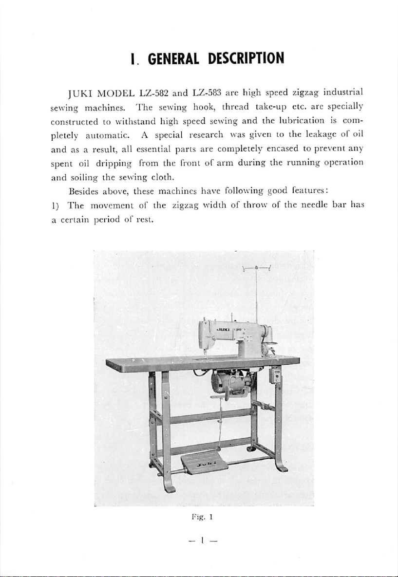
JUKI
sewing
constructed to withstand high speed sewing
pletely
and
spent oil dripping
and
1) The movement of the zigzag width of throw of the needle bar has
a
certain
MODEL
machines.
automatic. A
as a result, all essential parts are completely encased to prevent any
soiling
Besides above, these machines have following good features:
the
periodofrest.
LZ-582
The
sewing
special
from
the front of arm during the running operation
sewing cloth.
and
LZ-583
hook,
research
I \
are
thread
was
UUK.
p,
high
speed
zigzag
take-up
and
the lubrication is com
given
etc. are
to the
leakage
industrial
specially
of oil
Page 4
Due to this rest period feature of the needle bar, there is no width
of throw while the needle is piercing the cloth. This prevents the crack
ing of the needle eye or curving of the needle, thereby producing
attractive
garments.
2) The sewing hook driven by bevel gear
As the sewing hook is driven by the transmission power of the bevel
gear, the
"play"
of the sewing hook is negligible
and
also as the bevel
gear is protected by a case, its durability factor is very high.
3)
Thread
pull-off
lever
This machine is equipped with a thread pull-off lever to make the
pulling
the
outofthe
thread
sewing hook
tightening,
thread
eithertoright
easier.
or left.
Thus,
there
is no flaw
of
4) Special steel used on all essential parts
The zigzag forked rod, which is one of the important parts of the
zigzag machine, is made of specially heat-treated steel to prevent undue
depreciation
alloy.
smooth even at high speed
practically
and
With
these features, the
negligible.
the needle
and
bar
frame is made of special aluminium
machine
therefore depreciation
is very light
and
and
the
vibration
running
are
is
5)
Automatic
The
matic, eliminating hand-oiling
lubrication
lubrication to the essential frictional parts is completely
during
the
running
of the machine.
this feature, the production efficiency is greatly boosted up,
6)
Forced
When
from
drain
machine
oil
drain
the
oil accumulatesatthe
the
needle
device, this
and
returns
device
bar
spent
to
and
oil is
the
the
siphoned
oil
reservoir.
- 2 —
jaw
presser
bar.
up
of the
during
arm,
it invites oil leakage
However,
the
with
running
auto
With
this forced
of
the
Page 5
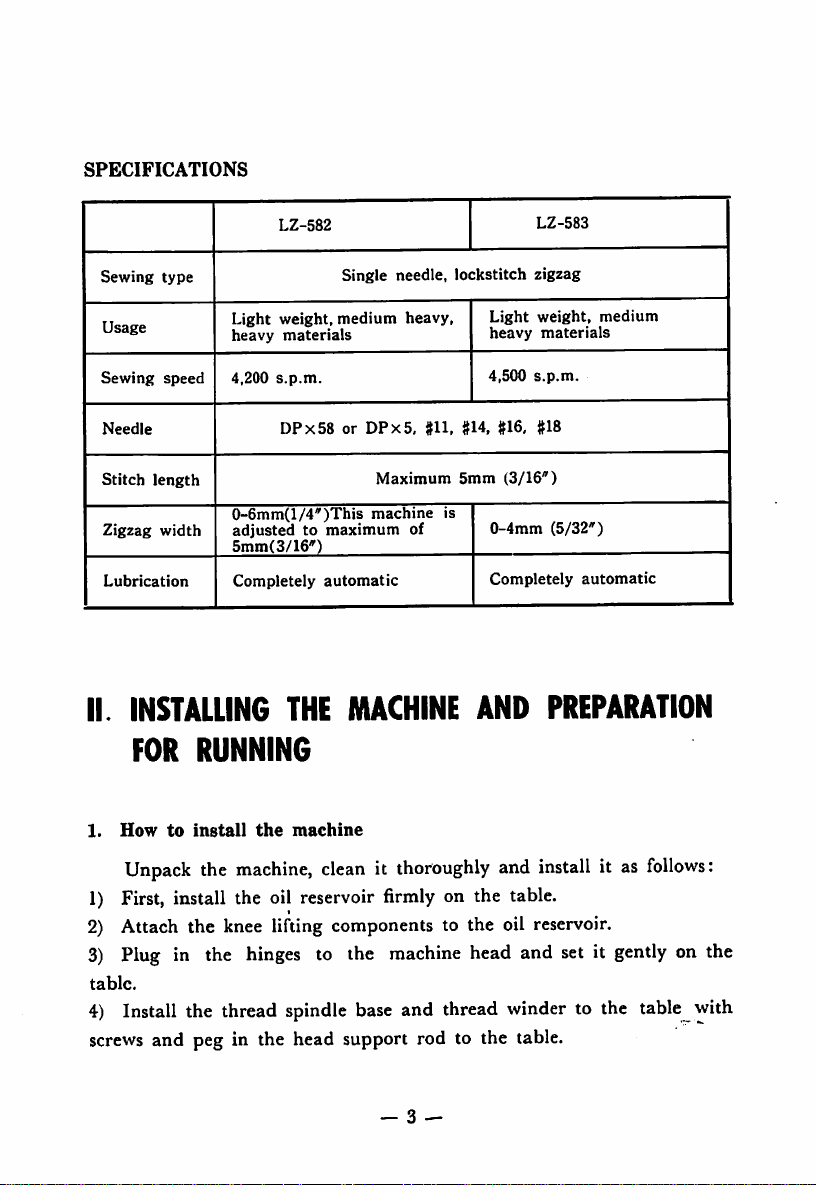
SPECIFICATIONS
Sewing
Sewing
Stitch
II.
type
Usage
speed
Needle
length
Zigzag
width
Lubrication
INSTALLING
FOR
LZ-582
Light
weight,
heavy
materials
4,200
s.p.m.
DPx58orDPx5.
0-6mm(l/4'')This
adjustedtomaximum
5mm(3/16")
Completely
THE
RUNNING
Single needle,
medium
automatic
heavy,
Maximum
machine
MACHINE
of
#11,
is
lockstitch
Light
heavy
4,500
1114,
#16. #18
5mm
(3/16")
0-4mm
Completely
AND
LZ-583
zigzag
weight,
s.p.m.
materials
(5/32")
automatic
medium
PREPARATION
1.
How
to
install
Unpack
the
the
machine
machine,
cleanitthoroughly
and
install
it as
follows:
1) First, install the oil reservoir firmly on the table.
2) Attach the knee lifting components to the oil reservoir.
3)
Plug in the
table.
hinges
to the
machine
head and set it
gently
on the
4) Install the thread spindle base and thread winder to the table with
screws
and peg in the head support rod to the table.
— 3 —
Page 6
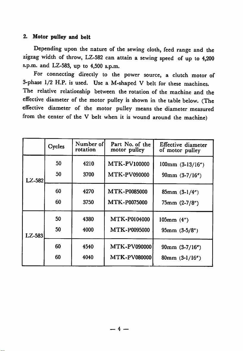
2.
Motor
pulley
and
belt
Depending
zigzag
s.p.m. and
widthofthrow,
upon
LZ-583,
the nature of the
LZ-582
up to
4,500
can
s.p.m.
sewing
cloth,
attainasewing
feed
speed
range
and the
ofupto4,200
For connecting directly to the power source, a clutch motor of
3-phase
1./2
H.P. is used. Use a M-shaped V belt for these machines.
The relative relationship between the rotation of the machine and the
effective
effective
from
LZ-582
LZ-583
diameter
of the
motor
pulleyisshowninthe
table
below.
diameter of the motor pulley means the diameter measured
the center of the V belt
Cycles
50
50
60
60
50
50
Number
rotation
4210
3700
4270
3750
4380
4000
when
it is
of
Part
motor
MTK-PVIOOOOO
MTK-PV090000
MTK-P0085000
MTK-P0075000
MTK-P0104000
MTK-P0095000
wound
No.ofthe
pulley
around the
Effective
machine)
diameter
of motor pulley
100mm (3-13/16")
90mm (3-7/16")
85mm
75mm (2-7/8")
105mm
95mm
(3-1/4")
(4")
(3-5/8")
(The
60
60
4540
4040
MTK-PV090000
MTK-PV080000
— 4 —
90mm
80mm
(3-7/16")
(3-1/16")
Page 7
Ill
HOW
TO
OPERATE
THE
MACHINE
1. Cautions on
*
Do
not
*
The
machine
side,itis
direction).
* Run the
month
nature of the work and the capability of the operator.
*
Rust
preventing
so after the machine is unpacked, be sure to clean this oil well and
before
machine a trial spin.
2.
system.
parts
repeated
threading
Lubrication
Ihese
oi the machine, returns to the oil reservoir
over
siphoned
oil sight
hook
resei-voirsofvarious
red
the mark
window,
Before
shaft
mark,
"HIGH"
When
somewhat and when it is well oiled, rotate the machine at the normal
speed.
operation
operate
the
rotates
machine
toward
without
the
counter-clockwise.Donot
machine
or
so
machines
The
up
operating the
bevel
fill
the
at a
moderate
and
gradually
oilisappliedtothis
the
machine,
are lubricated by
oil
which
again.
byapump
the drain condition can be carefully
gear
is applied by the plunger pump to all shaft
The
oil
whichisaccumulated
attachedtothe
machine,
reservoir
parts
(2)
every
themupagain.
(Fig. 2)
machineisto
be run
filling
up the
operator.
speedof3500-3800sp.m.
increase
fill
up
completely
fill
up the
with
2-3
days
The
oil
for
(As
rotate
the
the
speed
machine
the
main
oil,
fully.
and
reservoir
the
first
viewed
machineinthe
at the
oil
reservoir
automatic lubrication
and
shaft
hook
when
shouldbefilled
time,
oil
reservoir.
from
the
for
the
depending
upon
timeofpacking,
and
give
the circulation is
at the jaw part is
and
through
observed.
reservoir
Also,
they
inspect
fall
lower
(p and the
below
the
pulley
wrong
first
the
the
the
all
oil
the
up to
speed
— 5
Page 8
- •
'v.;
*
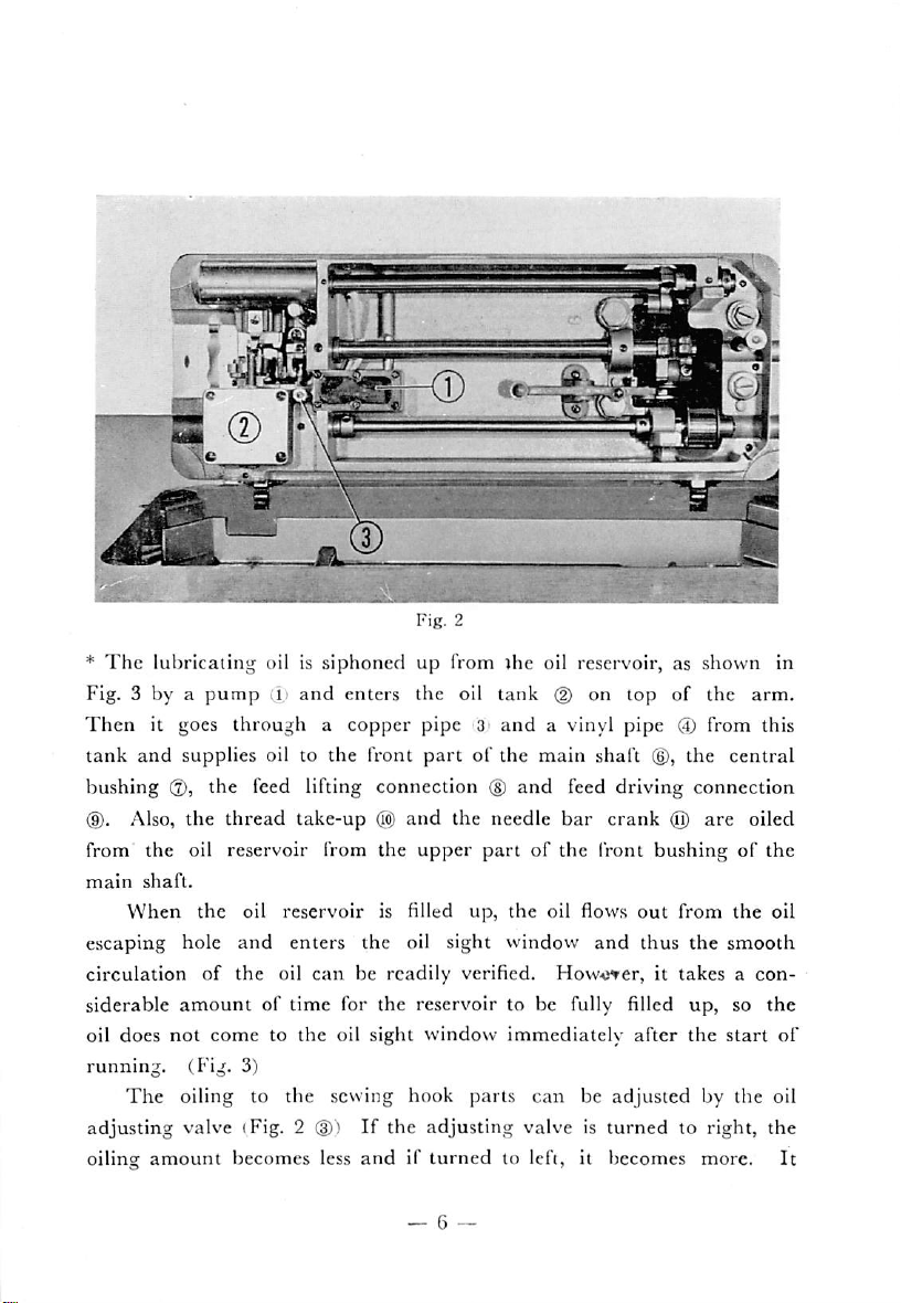
The
lubricating oil is siphoned up from ihe oil reservoir, as shown in
Fig. 3 by a
Then
tank
and
bushing
pump
(i)
and
enters
it goes through a copper pipe 3
supplies oil to the front
(2),
the feed lifting connection ®
d). Also, the thread take-up @
from the oil reservoir from the
main
shaft.
When
escaping hole
circulation
siderable
oil does
running.
The
adjusting valve (Fig. 2 ®)
oiling
the
oil reservoir is filled up, the oil flows
and
of
amount
not
cometothe
enters
the
oil
of time for the reservoir to be fully filled up, so
the oil sight window
can
be
oil sight
(Fig. 3)
oiling to the sewing hook
If
amount
becomes less
andifturned
. - '•.V*
the
oil
tank
@ on
and
a vinyl pipe
partofthe
main
and
and
the needle bar crank @ are oiled
upper
part
of the front bushing of the
top
shaft ®,
feed driving connection
out
and
thus
readily
the adjusting valve is
verified. How^j^er, it
window
immediately
parts
can
be
turned
after
adjusted
to lefi, it becomes more.
of
the
arm.
(J)
from this
the
central
from
the
the
smooth
takesacon
the
start
by the oil
to right, the
oil
the
of
It
_ 6 —
Page 9

11
10
6
Fig.
3
takes a certain time interval before the oiling amount to the sewing hook
becomes steady. This is because the oil is carried through the oil wicks
and
does not change immediately after adjusting, so have this in mind
when adjusting the oiling amount.
(.Note)
1) For lubrication, use
Esso Spinesso
Oil
No. 34.
JUKI
industrial oil (New Defrix No. 1) or
2) Do not run the machine before filling up the oil reservoir or
various
cially in summer.
other
oil
reservoirs.
3)
If
oil of low viscosity is used, it might invite oil leakage, espe
On
the other hand, if oil of too high viscosity is
used, the circulation of the oil becomes bad and might invite scorching
of parts.
4)
The
of shipping
amount
but
of oil for the sewing hook is adjusted at the time
this
amount
may
vary
according to the
temperature
the locality. Be sure to verify the correct amount by removing the
needle plate
and
by attaching a piece of paper, judge the
amount
of oil
of
— 7 —
Page 10

splashing the paper.
5)
When
lint
hardsorcloth
stick to the screenofthe
pump
screen. Constantly inspect the screen
dust
get
into
the
oil reservoir, it will
and
lower the working efficiency of the
and
clean it thoroughly when it's
clogged up.
6) When running the machine idly, be sure to fix the position of
the presser foot by means of the push button.
If
the machine is
run
idly with the presser foot raised up too high, it will result in malfunc
tioningofthe
3.
How
For
to
insert
LZ-582
machine.
the
and
LZ-583
needle
machines, use needle type
DPx58orDPx5
(135x5). There are many types of needles so please select the correct
type depending upon the thickness of the thread and the nature of the
sewing
material.
To insert the needle, rotate the hand wheel
and
raise up the needle
bar to the highest position ahd then loosen the needle clamping screw.
Hold the needle so that the long groove of the needle is facing the
operator and
goes in
insert
the
needle
and
clamp in the needle clamp screw tight.
deep into the
needle
hole as far as it
4.
Threads
The
needle
or left twist. But do
thick
thread.
5.
How
to
Set
the
wind
bobbin
thread
the
thread
or the bobbin thread could be either right twist
not
use inferior gradeofthread
bobbin
thread
winder
on
the
table
with
with flaws or too
screws
as
shown
Fig. 4. When the trip latch @ is knocked down, the bobbin winder ©
— 8 —
in
Page 11

Fig.
4
should correctly contact the belt. To wind the bobbin thread, insert
the
bobbin
0 deep into the
pulley
shaft as far as it
goes.
Then,
pass
the thread through the thread eye(Dand pass it between the thread
tension
disc
(§).
(The pressure of the thread tension disc is adjusted
according to the kind of thread and the woundcondition). Forsynthetic
thread like nylon etc., make it weak, somewhat.
Wind the tip of this thread around the bobbin from under, knock
down the trip latch ®
Run
the
machine
to make the
When the thread is not wound evenly to the bobbin, loosen the
screw
®,
bobbin
move
the thread
and
and
thread
contact the bobbin winder
wind
the
to be
tension
bobbin
woundtoabout
disc
thread
80%.
base(Dto right and leftto change
but
(D
to the belt.
use
the
screw
(§)
the slant of the winding thread and find the right winding position.
When
the winding is completed, the
trip
latch
will come off
and
the
rotation of the boobin winder will automatically stop. The winding of
the bobbin thread should be done during the running ot the machine.
(Note)
Lubricate the shaft part of the
— 9 —
bobbin
winder,
occasionally.
Page 12

6. Threading
the
machine (Fig. 5)
Pass the needle thread in the order of
(D--(§)
as shown in Fig, 5.
After the threading is completed, pull out the tip of the passed thread
about
10cm
(about
(Note) When using thick cotton thread
threads,
tuck
them
4").
in
between
the
1150
small
or over or nylon or tetoron
tension
discs
attached
to
the
thread guide bar and pass it through the 3-eyelet thread guide.
I
O
O
Fig.
7. Howtopass
Pass the bobbin
the
5
bobbin
thread
thread
(Fig. 6)
into the bobbin case, then pass it
Fig.
6
under
the
thread tension disc spring and as shown in Fig. 6, pass it through the
thread
eye in the front
and
into
the
sewing hook.
—10—
Page 13

8.
How
to
maintain
thread
tension
As shown in Fig. 7
and
8, the thread tension should be so maintained
that the intersecting of the needle thread and the bobbin thread should
come to
sobecareful.
the
Please note
a)
When
b)
When
c)
When
d)
When
e)
When
f)
When
center of
the
the
the
sewing cloth.
that
in the following cases, thread breakage may result,
thread
bobbin
passing is
thread
wrong
is all goneorbroken
the sewing hook is installed wrong
the sewing hook is bruised
the
the
needle
thread
thread
path
tension is too strong
is bruised
Fig.
9. Adjusting
To
change
7
the
zigzag width of throw (Fig. 9)
the
widthofthrowofthe needle, loosen the knob
Fig.
8
(T)
the name plate in the center of the arm and by matching the lever
to the designated graduation, set the knob.
— 11 —
of
(g)
Page 14

10.
The
knee
lifter
(Fig.
10)
Fig.
10
When you
first, raise
buttonQof
foot will come to a stop at
bring
down the presser foot,
will
come
11.
Adjusting
want
up
the
the face plate
down.
the
pressureofthe
the presscr foot to stay in the raised
presser foot by
the
knee lifter,
andifthe knee lifter is lowered,
about
6mm
(1/4") above the face plate. To
just
activate the knee lifter
presser
foot (Fig. 10)
To increase the pressure of the cloth pressing power,
If
it is
foot adjusting screw to your right.
become weaker.
kind
of sewing cloth
The
feeding power of the cloth varies according to the
but
it is
about
—12—
3kg~8kg.
turnedtoyour
up
then
push
and
turn
(6.6 lbs~17.61bs)
condition,
the
push
the
presser
presser foot
the presser
left, it will
Page 15

12. Adjusting the stitch
To change the stitch length, do as follows:
Push the push button
the hand wheel
carved
tell my
hand
part
When
the tip of the button has
feeling
wheel.
2;
of the
it) match the graduation
The
scaleonthe
leng^th
(Fig.
11)
(X)
attached to the upper
face
coverand rotate
slowly toward you until the button falls into the
ratchet
pawl.
fallen
into the
figure
hand
wheelisshowninmm.
carved
part,
with the mark on the
When this adjustment is completed, do not touch this button ever
during
the
running
of the machine.
(you
can
Fig.
11
IV ADJUSTING
1. How to remove
the
sewing hook (Fig. 12)
THE
MACHINE
The removing of the sewing hook is exactly like any other industrial
sewing machines.
The
only
difference is
— 13 -
that
the
hook is so-called front
Page 16

type which means it is facing the operator.
To
remove
raise
up
positioner
remove
the
lever®and
hook,
remove
the
needle
needle might break)
the
the
needle
installing
thread
by
the
is in
sewing
bar to
screw®and
pull-off
loosening
sewing
lowered
hook.
hook,
the
lever
set
the3set
(Be
position
tilt
the
uppermost
remove
screw
screws(Dwhich
careful
when
machine
position,
the
needle
remove
when
you
take
head
you
to the
remove
positioner.
the
thread
are
do
this
the
hook
other
the
needle
Next,
pull-off
clamping
because
out, the
side,
the
if
Fig.
12
Page 17

2.
Relation
between
the
needle
and
the
sewing
hook
The relationship between the needle and the sewing hook is as
shown in Fig. 13--lb.
At
first,
if the installed position of the zigzag forked rod triangle
cam
which throws
of
"needle
the
needle
barisnot
correct, the so-called malfunction
flow" occurs (when the needle is piercing the cloth, the
needle sways sidewaysj. Adjust the position of this cam as shown in
Fig. 14 so
that
it will function properly.
To determine the position of the needle throw, remove the cap (Fig.
5
(ij)!
near the arm thread guide bar,
loosen
the set screw of the bevel
gear of the main shaft, and as you watch the needle drop, adjust the
position by slowly sliding the position ol the gear
and
at the correct
position of the needle throw, tighten the set screw of the gear securely.
(Fig. 13, 14, 15, 16).
Start
motion
Throat
plate
Needle
of
Endofneedle
motion
I-g.
13
Needle hole of
Start
needle
Needle
motion
of
|
the
stitching
Fig.
Fig.
-
, 'il 1
throat
15
Needle
\]IEnd
.1
needle
motion
Throat
14
plate
16
—
of
Needle
Start
needle
motion
plate
stitching
Needle
of
Fig.
' End of
eedle
lotion
15
Page 18

Next,
to adjust the
position
of the
needle
drop,asshowninFig.
16,
the needle should be so adjusted that it will drop not too far to left ®
or too far to right
is the correct
correct position, loosen the eccentric shaft set screw ®
shaft(Dis rotated by a
left, so
adjust
To match the
see
that
no skip stitching should occur.
ing hook point
(Fig. 18)
The correct relation between the needle and the tip of the
hook
should
needle
needle
the
line
base.
center of the needle and the point of the sewing hook match each other.
bar
bar with the
needle
below
bar.
the
At this point, install the
Thus, when the needle has risen to
the center of the needle and the point of the
cide and the
the point of the hook becomes
(g)
but should throw uniformly to the center ©. This
position
with this eccentric shaft.
and
of the
sewing
the needle should be 0.0—0.1mm as a
screw
hook
needle
drop
driver, the
with the
The
position.
needle
needle
clearance between the sew
To adjust to this
and
will lean to right or
eye,
if the eccentric
it is
necessary
standard.
sewing
be such that with the width of throw at
to the lowest position, match the indicated line above the
lower
Next,
needle
bar
rotate
with
part of the
the
the
needle
hand
lower
sewing
bar vibrating
wheel
and
part of the
hook in such a way that the
1.75mm
above its
sewing
clearance
between
1.6—1.7mm.
the upper part of the
(Fig.
19)
"0",
bring the
base
match
needle
the
indicated
barvibrating
lowest
hook should coin
needle
eye
and set
point,
and
to
—16—
Page 19

I
-Mi
Fig.
17
3.
When
synthetic
threadisused
Fig.
(T)
Hook point
®
Needle
Fig.
16
18
When some synthetic thread is to be used for some purpose, attach
an Eslen case
between the 2 sheets of felt
(2)
on top of the thread guide plate
(D
and pass it through the thread hole ® of
(D,
pass the thread
the thread guide bar. When you do this, do not clamp the synthetic
thread on the thread tension disc (|) which is on the upper part of the
thread
guide
bar.
(Fig. 20)
—
17
—
Page 20

Fig.
For
5—lOgr,
19
synthetic
thread,
the needle thread
make
the
from-35-45
tension
gr, the stroke of the take-upspring
of
the
Fig.
bobbin
20
thread
from
from II—14mm and its tension about 20gr.
Also
the relative position of the sewing hook point with the needle
should be such
the
hook
from the
that
point
should coincide
lowest
when the
width
of throw is 0, the needle center
when
the
needle
bar
has risen 1.2—1.4mm
and
point, and also the needle bar and the sewing hook is
so set that the distance between the needle eye's upper point and the
pointofthe
♦
Winding
hook comes to
amount
of
the
1.7—2.1
bobbin
mm.
thread
The bobbin thread
should
be wound about
70%
during the
sewing.
Page 21

LZ-582
LZ-582
B-I524-582-0A0
B-J109-582-000
B-l
613-582-000
LZ-582
Q
^8
Jt\
0
B-I524-582-CA0
8-1109-582-000
B-I6I3-582-000
LZ-582
1
0
1
0
B-I524-582-DA0
B-II09-582-D00
B-I6I3-582-D00
B-I524-582-EA0
B-tl09-582-E00
B-I6I3-582-E00
< >
O 1
^
kil—t
Y '
-u
= 1
Page 22

LZ-582
0
LZ-582
Fffcl
B-I524-582-FA0
B-M09-582-F00
B-I6I3-582-F00
LZ-583
B-l524-5a3-0A0
~2I
S
E
"nnrn
"Tnrm
B-IS24-982-MAd
B-II09-582-M00
B-16I3-582-M00
LZ-583
B-I524-583-BA0
'=z
_ •
f
i
8-1109-583-000
8-1613-583-000
S-l.109-583-000
8-1613-583-000
Page 23

LZ-583
B-I524-583-CA0
LZ-583
B-I524-583-EA0
©
B-1109-583-000
B-I6I3-583-000
LZ-583
B-I524-583-FA0
B-II09-383-F00
'B-I6I3-583-F00
B-II09-583-E00
B-I6I3-583-E00
LZ-583
:
i
B-I524-583-6A0
B-II09-583-G00
B-I6I3-583-G00
•«!
Page 24

LZ-583
LZ-583
B-l524-5e3-HA0
B-II09-583-H00
B-I6I3-583-H00
LZ-583
8-1524-583-J
80
.
,
•3D
6-11.4
to
B-I524-5S3-JA0
B-M09-583-D00
B-I6I3-583-D00
LZ-583
rM1
0
o
8-1524-583-KAO
8-1109-583-000
8-1613-583-000
8-1109-583-000
B-I6I3-583-000
Page 25

LZ-583
fpte=®'
(0)
LZ-583
0
B-I524-583-KB0
B-II09-583-D00
8-1613-583-000
LZ-582, 583
No
Model
Needle
1
LZ-S82
B-U09-S82-000
2
'
a
3
K-1109-582-lX)0
4
3-1109-582-E00
5 "
B-I109-S82-F(I0
a
6
B-U09-582-M0O
1
LZ-583
B-1109-583-000
a
2
a 9 m
3
a
4
B-1I09-583-E00
S
'
B-1109-S83-FA0
6
•
B-1109-583-GA0
7
B-1109-S83-H00
a
8
B-1109-583-D00
a
9
a 9 9
10
11
12
•
B-I109-583-E00
LISTOFEXCHANGING
Plate
Presser
a a
# M
9 9
9 9
B-1S24-582-0A0
B-1524-S82-CA0
B-1S24-582-DA0
B-1524-S82EA0
B-1524-582-FA0
B-1S24S82-MA0
B-1524-583'0A0
B
1524-583-BA0
B-1S24-583-CA0
B-1524-S83-EA0
B-1S24-S83-FA0
B-1524-583GA0
B-1S24-S83-HA0
B-1524-583-JA0
B-1524-S83-JB0
B-1524-S83-KA0
B-1S24-S33-KB0
B-1S24-S83-LA0
Foot
PARTS
Feed
dos
B-I613-S82-000
9 9
B-16I3-682-D00
B-16I3-582-EOO
B-1613-582-F00
B-1613-582-M00
B-16I3-S83-000
a a
a a
B-1613^583-E00
B-1613
583-FOO
B-1613-S83-G00
B-1613-583-H00
B-1613-S83-DOO
'
a a a
B-1613-S83-E00
B-I524-583-LA0
B-II09-583-E00
B-I6I3-583-E00
WidthofThrow
6 mm
(1/4')
'
5 mm
(3/16')
'
6
mm
5
mm
4mm
(5/32')
'
a
4
mm
9
3 mm
(1/8')
2mm
(1/16')
3
mm
3
mm
9
•
< M
M
Usase&Remarks
Standard
parts
For
garments
requiring stepped stitches
For
light
weight
materials
For
overseaming
For
spun
tex
materials
Standard
type
parts
Standard
parts
For medium heavy materials requiring
stepped
stitches
For light weight materials requiring
stepped
stitches
For heavy weight materials requiring
stepped
stitches
For
light
weight
materials
tricot
stitches
Light weight materials, overseaming
Light
weight
width
Extreme
Zigxag
Extreme
Zigxag
Light
Zigxag
Light
Overseaming
materials
2mm
light
weight materials
width
less
than
light
weight
width
weight
width
9 9 9
weight
materials
less
than
materials
less
than
materials
widthofthrow
run
xigzag
3 mm
3mm
3mm
3mm
Page 26

TMYI
Head
Office&Plank
Business
Cable
Office:
Address:
JUKI
jiim
2-1,
23|
JUKI
8-chome,
Kabuki-cho,
TOKYO
INDV8TIIAI
Kokuryo-cho,
Shinjuku-ku,
Telex;
22967
Chofu-shi,
Tokyo,
JUKITK
C0..1TD.
Tokyo,
Japan
Japan
 Loading...