

Page 1

ENGLISH
LZ-2290A-SR / IT-100E / SC-916
INSTRuCTIoN MANuAL
Page 2

CoNTENTS
1. NAME oF EACH CoMPoNENT .................1
2. SPECIFICATIoNS ........................................2
2-1. Specications of the machine head .............2
2-2. Specications of the electrical box ..............2
3. STITCH PATTERN TABLE ..........................3
3-1. Initial value of the stitch pattern and the
table .................................................................4
4. INSTALLATIoN ............................................6
4-1. Installation of the sewing machine head .....6
4-2. Removing the needle bar stopper ................7
4-3. Attaching the knee-lifter ................................7
4-4. Adjusting the height of the knee lifter ..........7
4-5. Installing the electrical box ...........................8
4-6.
Connecting the power switch cord
(Japan and general export area)...................... 8
4-7. Installing the operation panel (IT-100E) .......8
4-8. Connecting the cords ....................................9
(1) Preparation of wiring .........................................9
(2) Connecting the connectors ............................ 10
4-9. Attaching the connecting rod ......................14
4-10. Adjustment of the pedal .............................15
4-11. Installing the thread stand .........................15
4-12. Installing the bird’s nest prevention
(CB) type sewing machine ...........................15
4-13. Lubrication ..................................................17
4-14. Test run .......................................................18
(1) Turn ON the power ......................................... 18
(2) How to operate the pedal ............................... 18
5. PREPARATIoN BEFoRE SEWING ..........19
5-1. Inserting the needle ....................................19
5-2. Removing the bobbin case ..........................19
5-3. Winding the bobbin thread ..........................19
5-4. Placing the bobbin case and the bobbin ...20
5-5. Threading the machine head .......................21
5-6. Adjusting the stitch length ..........................21
5-7. Adjusting the condensation stitching ........21
6. HoW To uSE THE oPERATIoN PANEL .22
6-1. Names and functions of
the respective sections ................................22
6-2. Before setting the pattern ............................24
(1) Limitation of the max. zigzag width ................ 24
(2) Setting the reference of stitch base line ......... 26
(3) Setting the feed amount ................................. 27
6-3. Basic screen ................................................28
6-4. List of the display pictographs of
each screen ...................................................29
6-5. Setting the sewing pattern ..........................52
(1) Selecting the zigzag pattern .......................... 52
6-6. Setting of the sewing shape ........................54
(1) 2-step zigzag,
3-step zigzag and 4-step zigzag stitch........... 54
(2) Scallop stitching ............................................. 56
(3) Blind stitch sewing ......................................... 59
(4) Custom pattern stitching ................................ 60
(5) T stitch, left ..................................................... 61
(6) T stitch, right................................................... 62
(7) Pattern 1 ........................................................ 64
(8) Pattern 2 (fagoting) ........................................ 65
(9) Pattern 3 ........................................................ 67
(10) Pattern 4 ...................................................... 69
6-7. Setting of the sewing speed ........................71
6-8. Reverse feed stitching .................................71
(1) Standard condensation .................................. 72
(2) 2-point condensation ...................................... 74
(3) Condensation custom .................................... 75
(4) Comparision table of
the reverse stitch of each shape .................... 76
6-9. Selection of the kind of stitching ................77
(1) Overlapped stitching ...................................... 77
(2) Programmed stitching .................................... 78
6-10. Custom pattern ...........................................80
(1) Custom pattern setting ................................... 80
(2) New creation of the custom pattern .............. 81
(3) Custom pattern edit ........................................ 82
(4) Pattern sewing registration,
custom pattern copy and
custom pattern deletion of the custom pattern
.... 82
6-11. Condensation Custom ...............................84
(1) Condensation custom setting ......................... 84
(2) Condensation custom edit ............................. 85
6-12. Pattern stitching .........................................87
(1) Setting the pattern stitching ........................... 87
(2) Registering the pattern stitching .................... 89
(3) Copy and deletion of the pattern stitching ...... 89
6-13. Continuous stitching .................................91
(1) New creation of the continuous stitching ....... 91
(2) Continuous stitching edit ................................ 92
(3)
Copy and deletion of the continuous stitching
.... 94
6-14. Cycle stitching ............................................95
(1) New creation of the cycle stitching ................. 95
(2) Cycle stitching edit ......................................... 95
(3) Copy and deletion of the cycle stitching ......... 97
(4) Teaching ......................................................... 98
(5) Performing the constant-dimension stitching
using the cycle stitching ................................. 99
6-15. Counter ........................................................99
(1) Thread trimming counter ................................ 99
(2) Bobbin thread counter .................................... 99
6-16. Information ................................................100
(1) Sewing common data .................................. 101
(2) Sewing management information ................ 103
(3) Communication mode .................................. 106
6-17. Setting for functions ................................ 110
(1) How to change over to
the function setting mode..............................110
(2) Function setting list ......................................113
(3)
Detailed explanation of selection of functions
.... 117
6-18. External interface ....................................122
(1) Media slot ..................................................... 122
(2) Ethernet port ................................................ 122
(3) RS-232C port ............................................... 122
(4) General input port (Production control switch
connecting connector) ................................. 122
6-19. Setting the maximum sewing speed ....123
6-20. Panel memory switch setting ................123
7. SEWING ...................................................125
7-1. Adjusting the thread tension .....................125
7-2. Adjusting the pressure of the presser foot ....
126
7-3. One-touch type reverse feed stitching
mechanism ..................................................126
7-4. Pattern 2 (fagoting) sewing .......................127
7-5.Hand switch .................................................128
i
Page 3

8. STANDARD ADJuSTMENT ....................129
8-1. Adjusting the amount of oil in the hook ..129
8-2. Adjusting the amount of
lubricating to face plate section ...............129
8-3. Adjusting the height of the presser bar .....130
8-4. Adjusting the micro-lifting
mechanism of the presser foot .................130
8-5. Height and inclination of the feed dog .....130
8-6. Hook adjusting mode .................................131
8-7. Attaching / removing the hook ..................132
8-8. Adjusting height of the needle bar ...........133
8-9. Adjusting the needle-to-hook timing
and the needle guard .................................133
8-10. Adjusting the stop position of
the needle ....................................................134
8-11. Adjusting the thread trimmer ..................134
8-12. Adjusting the needle thread
feeding device ............................................135
8-13. Adjusting the bird's nest prevention
(CB) type wiper ...........................................136
8-14. Replacing procedure of the bird’s nest
prevention (CB) type presser knife ...........137
9. MAINTENANCE .......................................138
9-1. Replacing the power fuse ..........................138
9-2. Adjusting the contrast of
the operation panel display .......................139
9-3. Draining
(Bird’s nest prevention (CB) type only) ....139
9-4. Cleaning the dust bag
(Bird’s nest prevention (CB) type only) ....139
9-5. Cleaning the cooling fan installed on the
under cover .................................................140
9-6. Cleaning the hook section .........................140
9-7. Cleaning the rear cover of
the control box ...........................................140
9-8. Cleaning the operation panel screen ......140
9-9. Replacing procedure of
the hook shaft oil wick ...............................141
9-10. Applying the exclusive grease ................141
9-11. USB port ....................................................142
10. AT A TIME LIKE THIS ! ..........................143
11. ERRoR DISPLAY...................................144
11–1. Error code list (Error display in panel) ....145
12. TRouBLES AND CoRRECTIVE
MEASuRES.............................................149
ii
Page 4
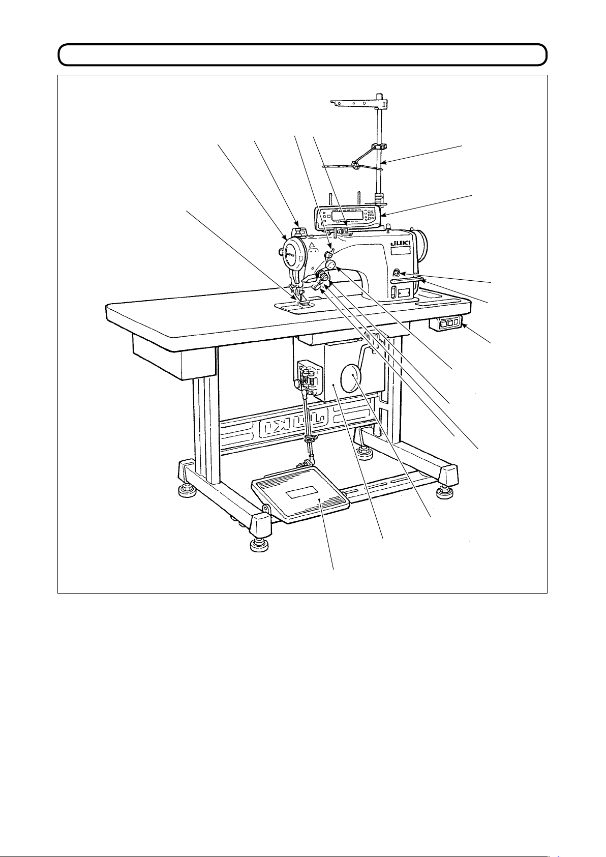
1. NAME oF EACH CoMPoNENT
!3
!2
4
3
2
!4
!1
!5
!7
o
Needle thread draw-out device
1
Wiper switch
2
Thread take-up cover
3
Finger guard
4
Thread tension controller (Rotary tension)
5
Electrical box
6
Pedal
7
u
Knee lifter lever
8
Power switch
9
Hand switch
!0
O
peration panel
!1
Bobbin winder
!2
Tension controller No.1
!3
(Pre-tension)
Thread stand
!4
y
q
t
!0
!6
i
Oil supply opening
!5
Mirror inversion switch
!6
Reverse feed control lever
!7
– 1 –
Page 5
– 2 –
2. SPECIFICATIoNS
2-1. Specications of the machine head
Model
Minute-quantity
lubricating type
LZ-2290A-SR-7-WB LZ-2290A-SR-7-CB
Application Light-weight materials to medium-weight materials
Max. sewing speed 5,000 sti/min (*1)
Max. zigzag width 10 mm (*2)
Max. feed pitch 5 mm (normal/reverse feed)
Stitch pattern 14 kinds 20 patterns
Needle SCHMETZ 438 #75 (Needle at the time of delivery)
Oil used JUKI New Defrix Oil No. 1
Thread trimmer With
Feed method Standard feed (Computer controlled system)
Wiper method Front sweeping method Side sweeping method
Thread clamp method ——— Air clamp method
- Equivalent continuous emission sound pressure level (LpA) at the workstation:
Noise
A-weighted value of 80 dB; (Includes KpA = 2.5 dB);
according to ISO 10821- C.6.2 -ISO 11204 GR2, at 4,600 sti/min.
* 1. The max. sewing speed is set to 4,000 sti/min at the time of delivery (depending on the delivery area).
•
The speed is limited by setting of the zigzag width of the sewing pattern and feed amount since the
speed is controlled by the amount of zigzag width per stitch and feed amount.
•
Properly set the number of revolution in accordance with the product to be sewn and process.
* 2. Max. zigzag width is limited to 8 mm at the time of standard delivery.
2-2. Specications of the electrical box
For general export
Supply voltage Single phase 200V / 220V / 240V 3-phase 200V / 220V / 240V
Frequency 50 Hz / 60 Hz
Electric power 600VA
Operating environment Temperature : 0 to 40˚C Humidity : 90% or less
For CE
Supply voltage Single phase 220V / 230V / 240V
Frequency 50 Hz / 60 Hz
Electric power 600VA
Operating environment Temperature : 0 to 40˚C Humidity : 90% or less
For JUS
Supply voltage Single phase 100V / 110V / 120V 3-phase 200V / 220V / 240V
Frequency 50 Hz / 60 Hz
Electric power 600VA
Operating environment Temperature : 0 to 40˚C Humidity : 90% or less
Page 6
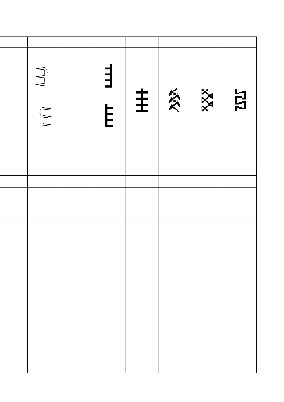
3. STITCH PATTERN TABLE
Name of pattern
Straight stitch
2-step zigzag stitch
3-step zigzag stitch
4-step zigzag stitch
Standard
scallop
Crescent
Scallop
(right)
scallop
Equal-width
scallop
Equal-width
scallop
Stitch pat-
tern
Number of stitches
for pattern
1
2
4
6
24
12
Max.zigzag
width
____
Remarks
Standard
scallop
Crescent
Scallop
(left)
Blind stitch (right)
Blind stitch (left)
Custom pattern
T stitch (left)
T stitch (right)
scallop
Equal-width
scallop
Equal-width
scallop
24
10
12
a
2 + a
a
—— 500
3
Pattern 1
Pattern 2 (fagoting)
Pattern 3
Pattern 4
6
– 3 –
Page 7
– 4 –
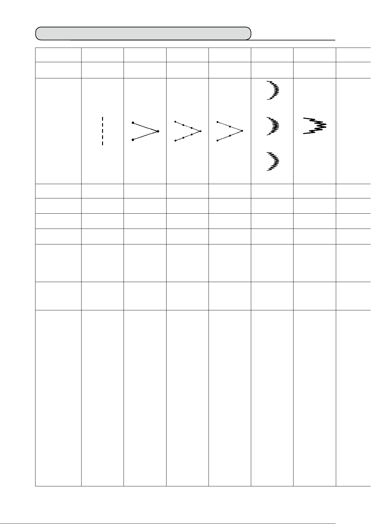
3-1. Initial value of the stitch pattern and the table
1 2 3 4 5 6 7 8 9 10 11 12 13
Zigzag width
Normal feed
amount
Reverse feed
amount
Number of
stitches
Related input
Straight stitch
2-step zigzag
stitch
4-step zigzag
stitch
3-step zigzag
stitch
Scallop 24
stitches
Standard scallop
Crescent scallop
Equal-width scallop
Scallop 12
stitches
Equal-width scallop
—— 4.0 8.0 6.0 8.0 8.0 3.0 —— 3.0 6.0 6.0 6.0 6.0
2.0 1.5 1.0 1.0 0.5 0.8 1.5 —— 2.5 2.5 1.6 2.1 2.0
0.0 0.0 0.0 0.0 0.0 0.0 0.0 —— 0.0 0.0 - 2.0 2.4 - 2.0
—— —— —— —— —— —— 4 —— —— —— —— —— ——
P. 31, 54,
55
P. 32, 54,
55
P. 32, 54,
55
P. 32, 54,
55
P. 32, 33,
56, 57, 58,
101, 102
P. 32, 33,
56, 57, 58,
101, 102
Related
mechanical
adjustment
Remarks
P. 128 P. 128 P. 127
Page 8
Blind stitch
a
Custom pattern
T stitch Pattern 1
Pattern 2
(Fagoting)
Pattern 3 Pattern 4
(Left)
———
a
(Right)
P. 34, 59 P. 45, 60,
80, 81, 82,
83, 98, 99,
101, 102
(Left)
(Right)
P. 35, 36,
37, 38, 61,
62, 63
P. 37, 38,
64, 65
P. 39, 40,
65, 66, 67
P. 41, 42,
67, 68
P. 43, 44,
69, 70
There are cases where the
stitch shapes
are not
stabilized in
case of some
patterns which
frequently
repeat normal
and reverse
feed stitching.
Use the machine at the
sewing speed
of approximately 2,000
sti/min.
– 5 –
Page 9
– 6 –
4. INSTALLATIoN
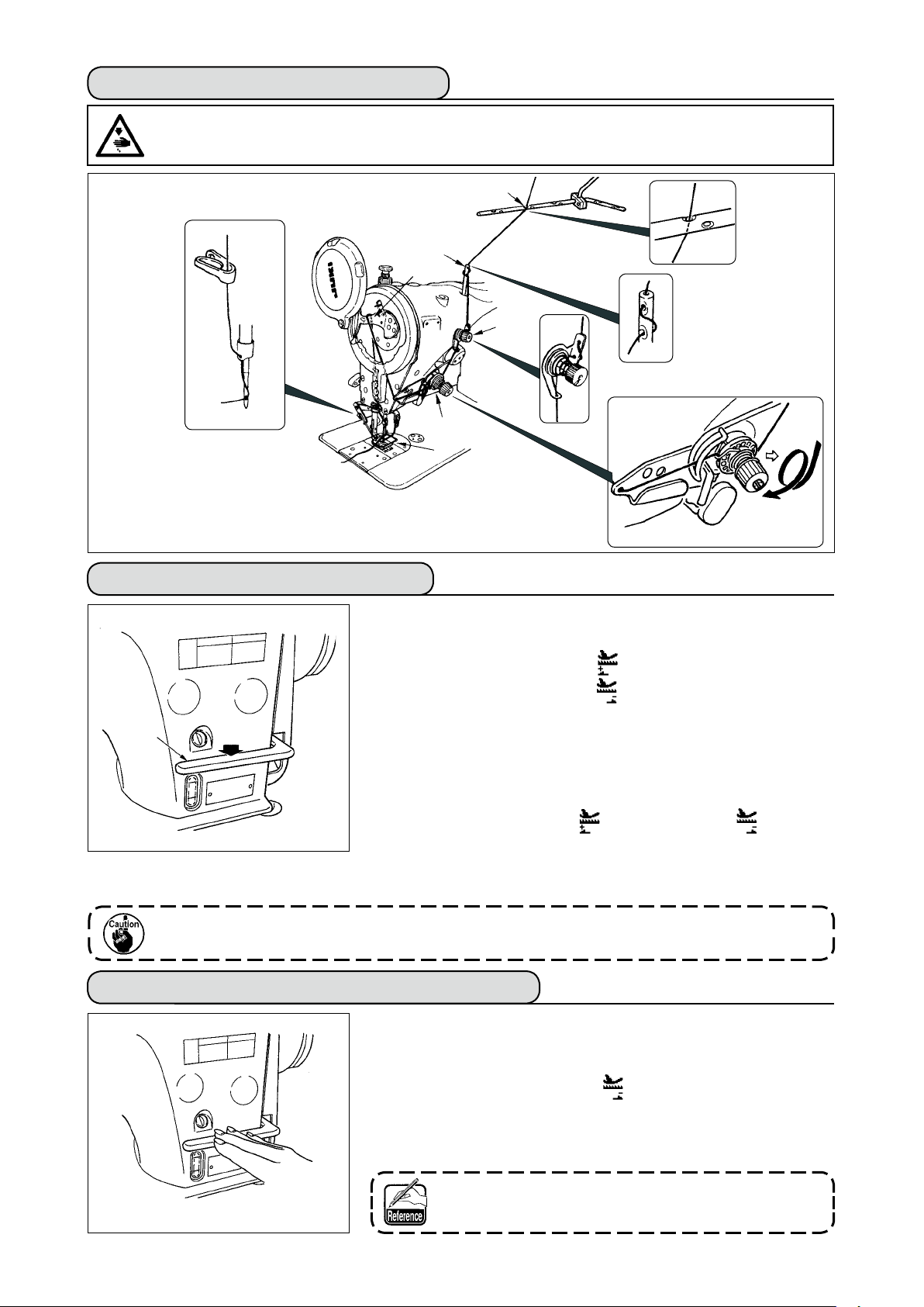
WARNING :
• Perform the installation of the sewing machine by the technical personnel who have been trained.
• To prevent personal injury, ask our dealer or the electrician for electric wiring.
• Be sure to perform the work with two persons or more when transporting the sewing machine and use a
lorry when moving it.
• To prevent personal injury caused by abrupt start of the sewing machine, do not connect the power plug
until the set-up of the sewing machine is completed.
• Be sure to earth the ground wire to prevent personal injury caused by leak.
• Be sure to attach safety protection cover, ger guard, etc.
4-1. Installation of the sewing machine head
Installing the under cover
1) The under cover should rest on the four corners
3
3
of the machine table groove.
23.5 mm
2
8
3
7
1
1
A
4
5
B
1
19.5 mm
3
2) Fix two rubber seats 1 on side A (operator’s
side) using nails 2 as illustrated above. Fix two
cushion seats 3 on side B (hinged side) using a
rubber-based adhesive. Then place under cover
on the xed seats.
4
3) Remove air vent cap 5 attached to the machine
bed. (Be sure to attach cap 5 when transporting
the machine head in the state that the machine
head is removed from the machine table.)
If the sewing machine is operated
without removing air vent cap 5, oil
leakage from gear box portion 7 may
occur.
4) Fit hinge 1 into the opening in the machine bed,
and t the machine head to table rubber hinge 8
before placing the machine head on cushions 3
on the four corners.
6
4
1
5) Attach head support rod 6 to the machine table.
Page 10
4-2. Removing the needle bar stopper
Remove needle bar stopper 1 for transportation.
1
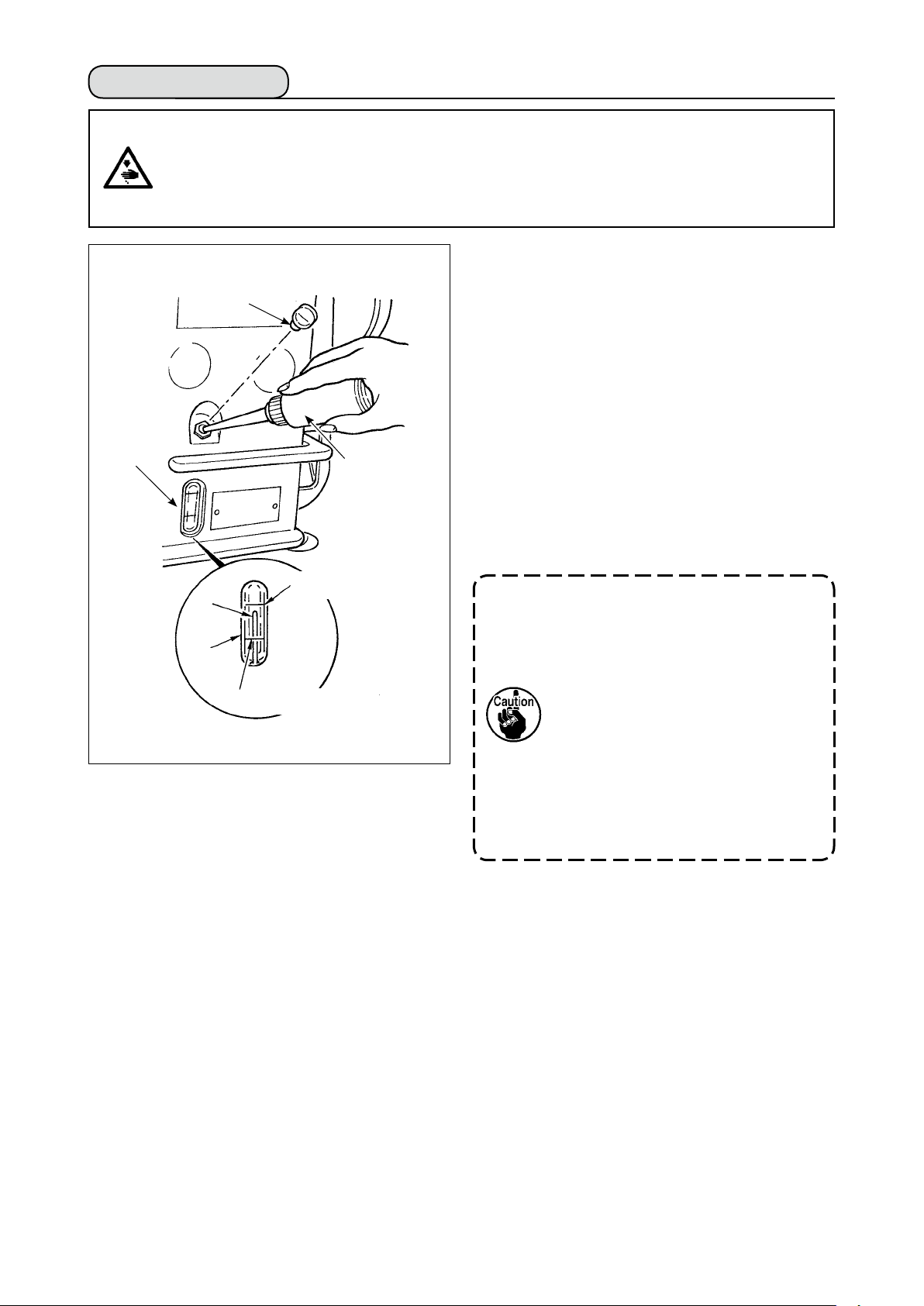
4-3. Attaching the knee-lifter
Insert knee-lifter into attaching hole 2 and tighten it
with bolt 3.
* Adjust the position of knee lifter pad 1 to a conve-
mm
220
2
3
* In case of the machine with AK device, knee lifter
Keep the needle bar stopper which
has been removed, and install this
needle bar stopper when transporting
the sewing machine.The needle bar
stopper may be cut when it is strong-
ly drawn out. Slightly move the needle
bar to the right or left and slowly draw
out the needle bar stopper.
nient place. For the reference dimension, the posi-
tion is 220 mm from the bottom face of table.
pad 1 is optional. (Part No. 22934251)
1
4-4. Adjusting the height of the knee lifter
1) The standard height of the presser foot lifted using
the knee lifter is 10 mm.
2)
You can adjust the presser foot lift up to 15 mm
using knee lifter adjust screw ❶
1
.
Do not operate the sewing machine in
the state that presser foot 3 is lifted
by 10 mm or more since needle bar 2
and presser foot 3, or wiper 4 and
presser foot 3 come in contact with
each other.
4
2
3
– 7 –
Page 11
– 8 –
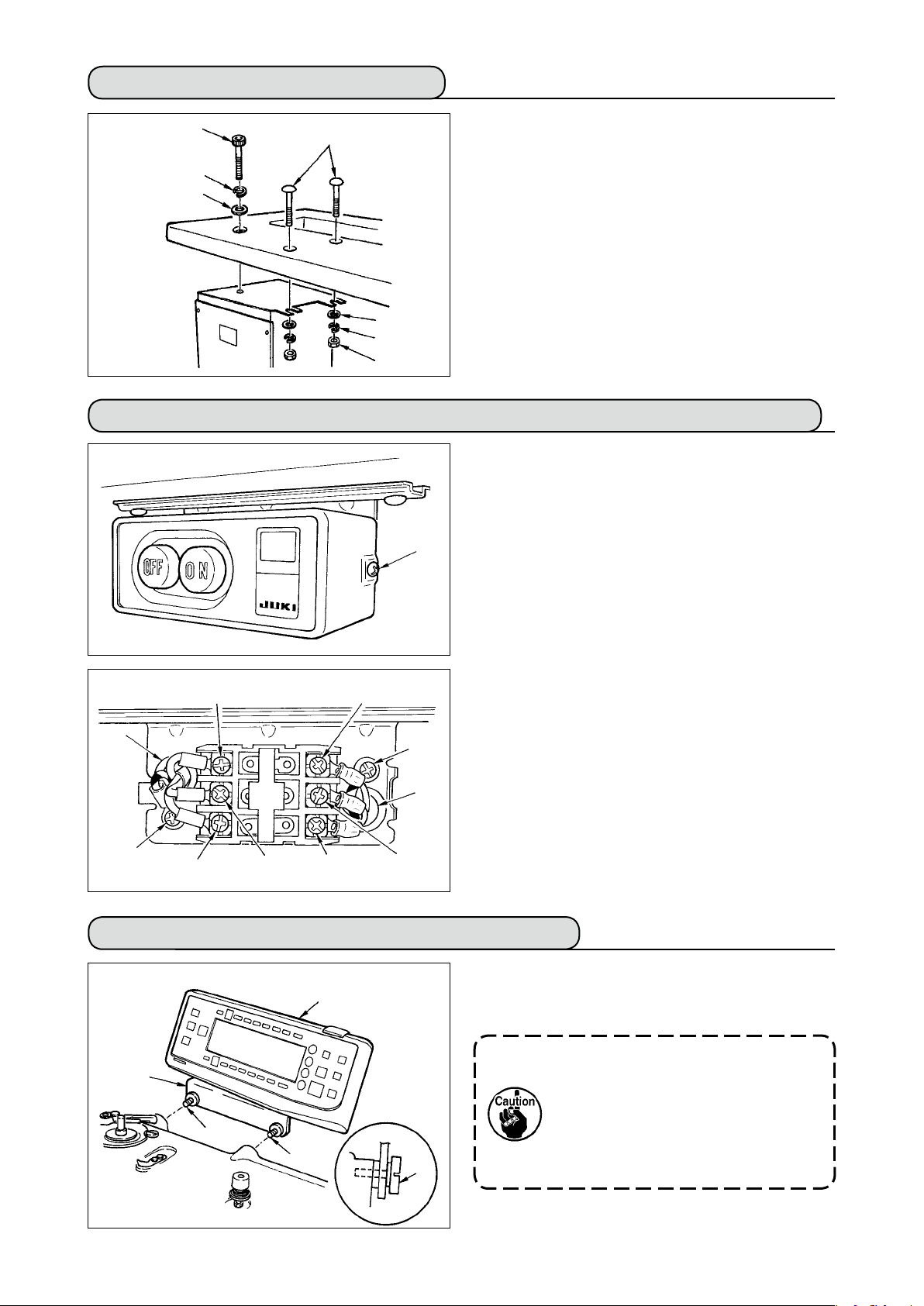
4-5. Installing the electrical box
5
1
6
7
Install the electrical box on the underside of the table
at the location illustrated using round-head bolt 1,
plain washer 2, spring washer 3 and nut 4 sup-
plied with the machine, and using bolt having hex-
agonal indentation on the head 5, plain washer 6
and spring washer 7 supplied with the machine.
2
3
4
4-6.
Connecting the power switch cord (Japan and general export area)
1) Loosen screw 1 located on the side of the power
switch supplied as accessories and remove the
power switch cover.
2) Connecting the input power cord of electrical box
When the input power cord of electrical box is 4P
¡
1
Put 4P cord from hole A of the power switch and
securely x green/yellow cord to 5, white cord to 2,
black cord to 3 and red cord to 4 with screws.
When the input power cord of electrical box is 3P
¡
Put 3P cord from hole A of the power switch and
securely x green/yellow cord to 5, brown cord to
and sky blue cord to 3 with screws.
2
3) Connecting the power cable supplied as accessories
In case of 3-phase power cable
2
6
¡
Put power cable from hole B of the power switch,
A
9
and securely fix green/yellow cord to 9, white
cord to 6, black cord to 7 and red cord to 8 with
screws.
In case of single phase power cable
B
¡
Put power cable from hole B of the power switch,
and securely x green/yellow cord to 9 and other
5
4
3
8
7
cords to 6 and 7 with screws. 8 is not used.
4) Installing the power switch cover
Securely tighten screw 1 located on the side of
the power switch.
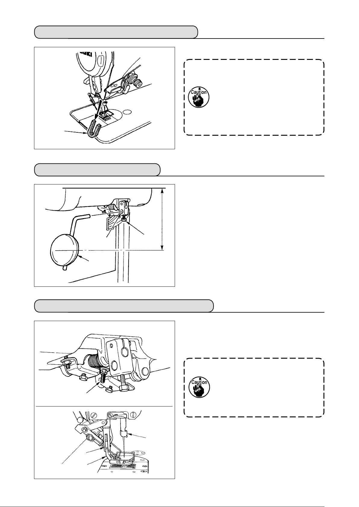
4-7. Installing the operation panel (IT-100E)
1) Install operation panel 1 on the machine head
1
2
3
3
3
using screws 3 which have been assembled to
panel installing bracket 2.
1. Do not disassemble the operation
2. Clamp the cord coming from the
panel to prevent it from breakage.
panel and that of the machine head
with the clip band supplied as ac-
cessories.
Page 12
4-8. Connecting the cords
WARNING :
• To prevent personal injury caused by abrupt start of the sewing machine, carry out the work after turning
OFF the power switch and a lapse of 5 minutes or more.
• To prevent damage of device caused by maloperation and wrong specications, be sure to connect all the
corresponding connectors to the specied places.
• To prevent personal injury caused by maloperation, be sure to lock the connector with lock.
• As for the details of handling respective devices, read carefully the Instruction Manuals supplied with the
devices before handling the devices.
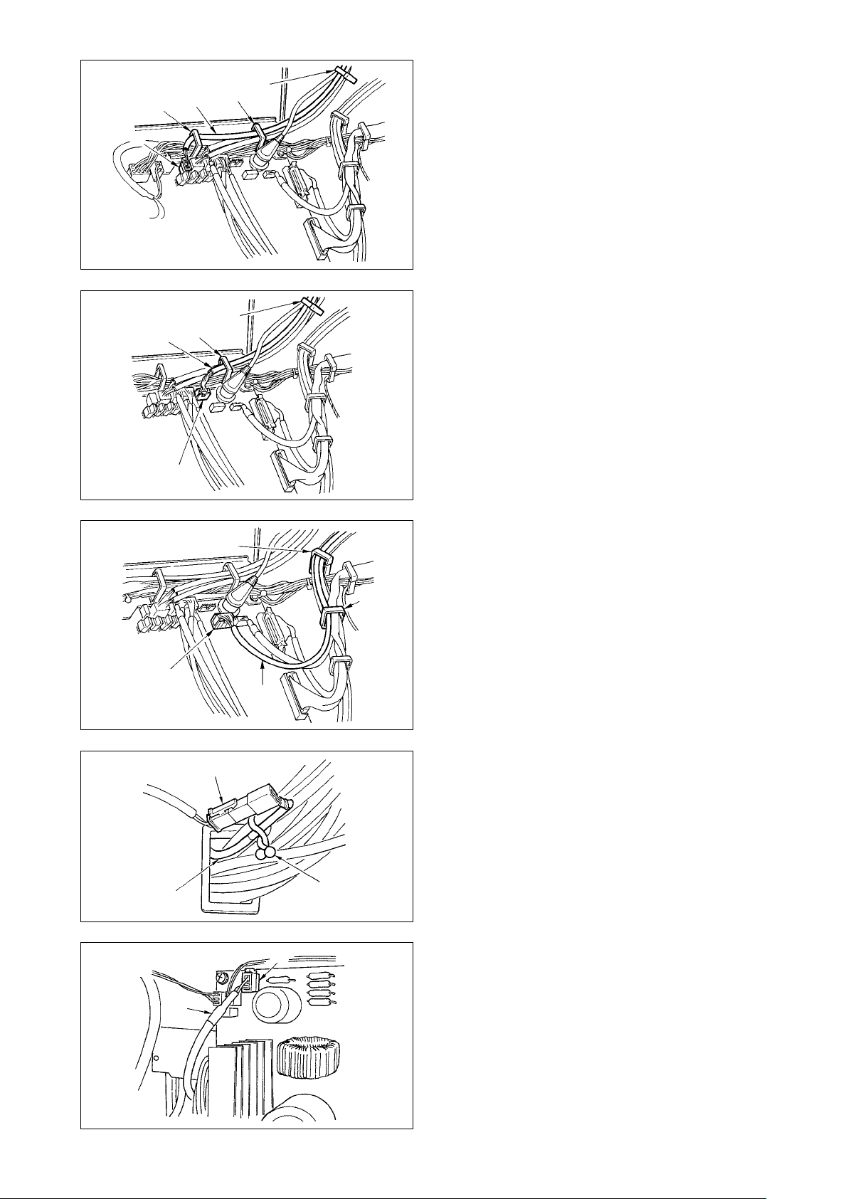
(1) Preparation of wiring
A
1) Pass the cords coming from the machine head to
the underside of the table through hole A in the
table.
D
2) Loosen screws D and lift cord presser plate C of
cord passing hole B located on the front cover to
B
C
the top and temporarily tighten the plate.
3) Remove four screws fixing the rear cover of
the electrical box.
(Caution) Do not touch other screws.
When opening the rear cover, pressing it with your
hands, slowly open it by approximately 70˚ until it
Slowly
E
stops as illustrated.
Be sure to lend your hand to the
rear cover in order not to let the rear
cover fall. In addition, do not apply
force to the rear cover opened.
4)
j
b
a
e
f
c
d
Remove the locks of cord clamps a, b, c, d, e, f and j.
How to remove the cord clamp
1
Lightly pressing
1
Pull down the clamp.
2
The clamp goes up.
3
3
1
2
* See P.14 for how to lock the cord clamp.
– 9 –
Page 13
– 10 –
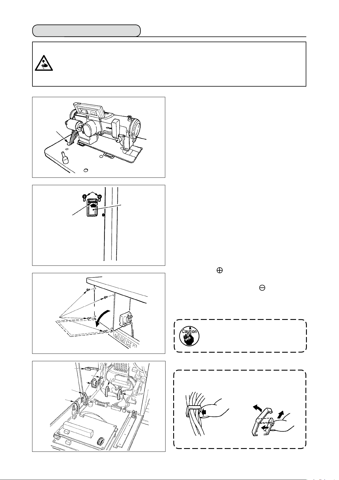
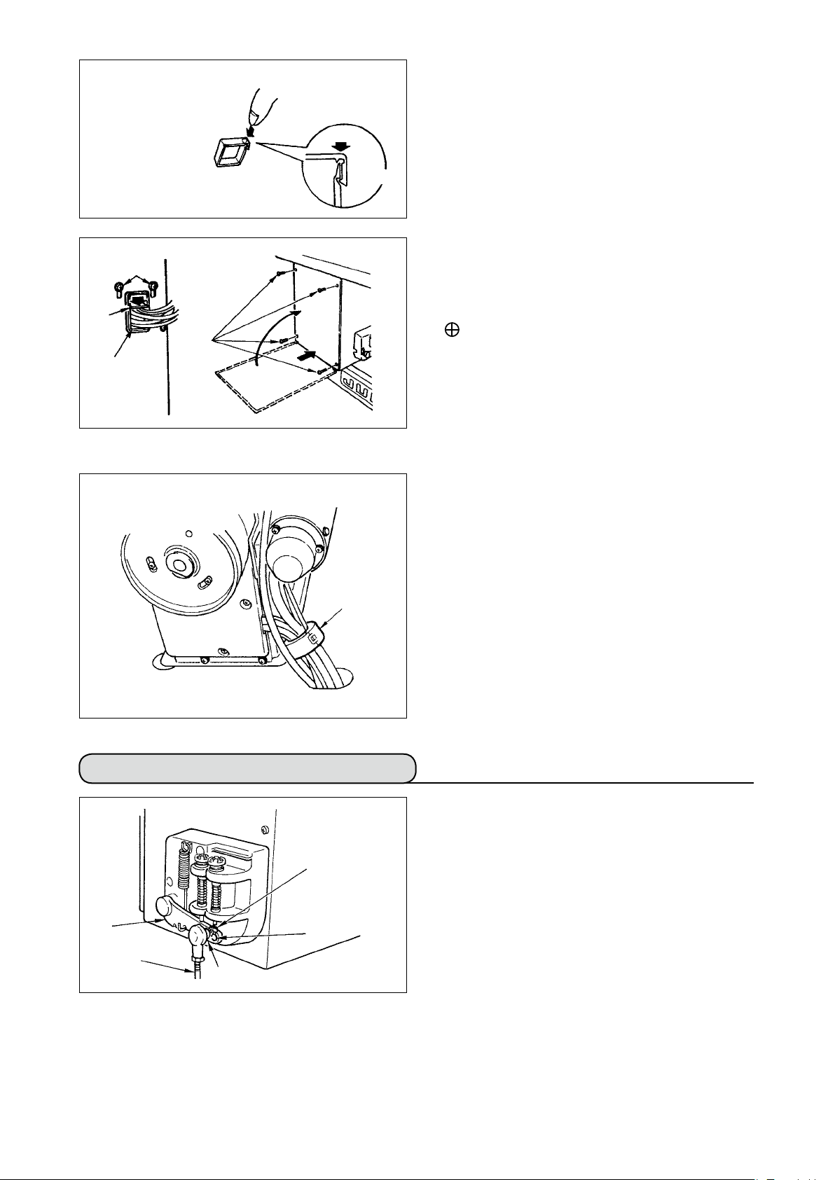
(2) Connecting the connectors
• Each connector has the inserting direction. Check the direction and securely insert it.
(In case of the type with lock, insert up to the lock.)
• If the connector is forcibly inserted, trouble or accident will be caused.
• Never pull out the connectors inserted at the time of delivery.
• The sewing machine fails to work if the connectors are not properly inserted. Not only
the problem such as the error warning or the like but also breakage of the sewing machine or electrical box will occur.
B
1
b
5) Insert yellow/green earth cord 1 coming from the
machine head inside the electrical box through
front cover through hole B, and pass it through
cord clamp “b” as illustrated and tighten it with
screw at the position 2 in the illustration.
Connect cords in the following order.
2
6) Insert white square connector 9P black cord 3
coming from the machine head inside the electri-
cal box through front cover through hole B, and
B
insert it into connector CN38 4 of the circuit
board attached to the front cover.
3
4
7) Insert white connector 4P black cord 5 coming
from the machine head inside the electrical box
B
through front cover through hole B, and insert it
into connector CN21 6 of the circuit board at-
6
5
tached to the front cover.
8) Insert white connector 26P cord 7 coming
B
from the operation panel inside the electrical
box through front cover through hole B, pass it
through cord clamps “a”, “c” and “d”, insert it into
7
a
d
c
8
connector CN34 8, and lock it.
Page 14
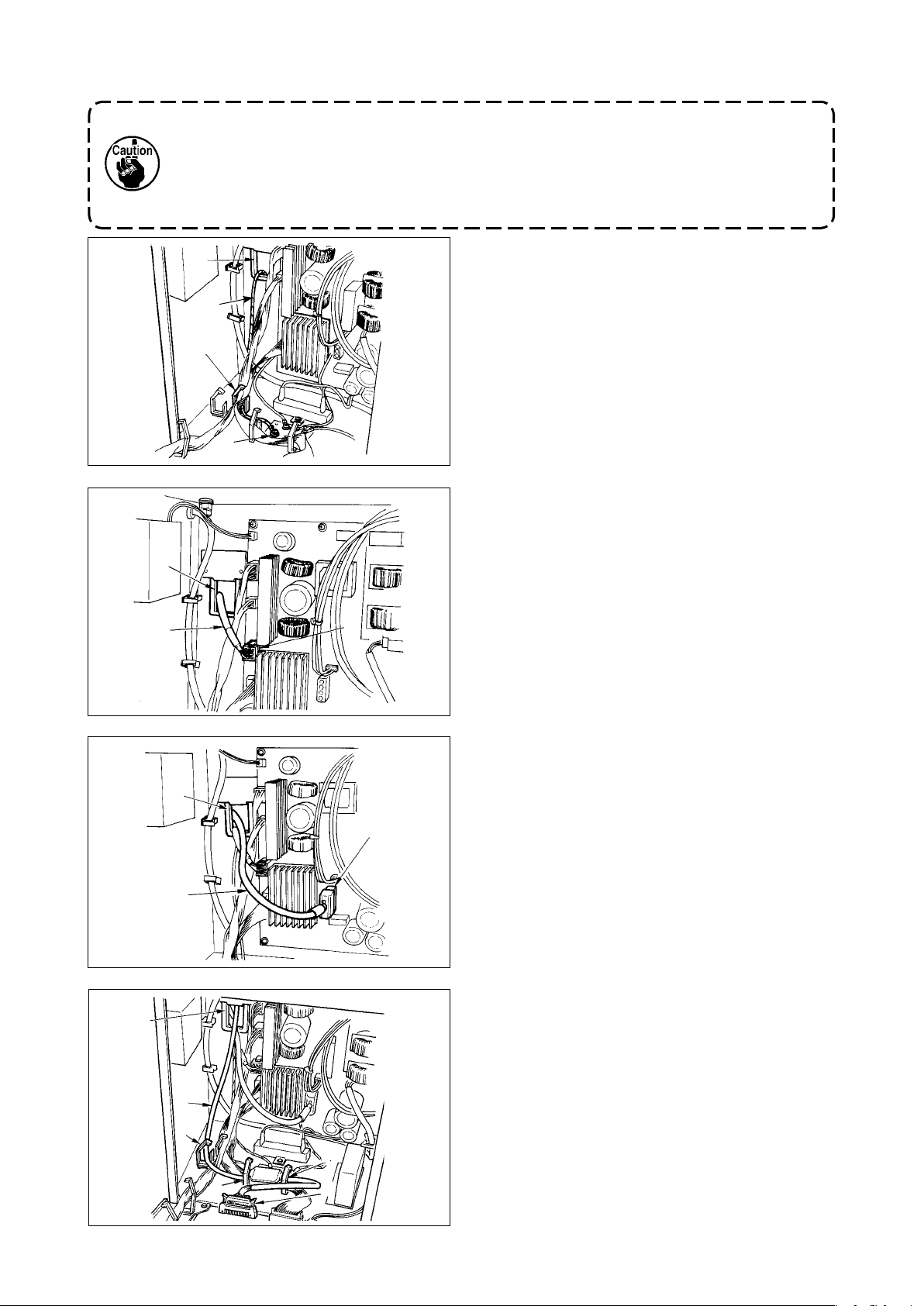
9) Insert black connector 4P white cord 9 coming
from the machine head inside the electrical box
through front cover through hole B, and insert it
9
a
c
!0
and c.
into connector CN31
through cord clamps a
!0
10) Insert gray round connector 7P cord
!1
com-
ing from the machine head inside the electrical
box through front cover through hole B, pass it
j
!1
!2
through cord clamp “j”, and insert it into connec-
tor CN30 !2.
11) Insert white connector 12P cord !3 coming from
the machine head inside the electrical box through
front cover through hole B, pass it through cord
clamps “a”, “c”, “d” and “g”, and insert it into con-
a
c
d
!3
!4
g
nector CN53 !4.
Close cord clamps “a”, “c” and “d”.
!7
!5
12) Insert white connector 6P cords !5 coming from
the machine head inside the electrical box through
front cover through hole B, pass it through cord
j
clamps “e” and “j”, and insert it into connector
CN54 !6.
e
!6
13)-1 Insert white connector 10P cord
connector 2P cord
coming from the machine
!7
and blue
!9
head inside the electrical box through front
cover through hole B, pass them through cord
!8
clamps “e”, “f” and “j”, and insert the white 10P
into connector CN51 @0 and the blue 2P into
CN46 !8.
@0
!9
– 11 –
Page 15
– 12 –
!9
13)-2 Insert white connector 10P cord !9 coming from
the machine head to the rear of the connector
as shown in the gure.
@1
14) Insert black square connector 8P cord @1 com-
ing from the machine head inside the electrical
box through front cover through hole B, pass
it through cord clamps “e”, “f”, “h” and “j”, and
h
@2
insert the black square 10P into connector CN72
.
@2
15) Insert black connector 4P cord @3 coming from the
machine head inside the electrical box through
front cover through hole B, pass it through cord
@3
@4
h
clamps “e”, “f”, “h” and “j”, and insert the black 4P
into connector CN73 @4.
16) Close cord clamps “e”, “f” and “j”.
j
e
f
Page 16
@6
f
@7
@8
@5
When the Auto-lifter (AK121) is used :
j
e
j
e
17) Insert white connector 2P cord @5 coming from
the machine head inside the electrical box
through front cover through hole B, pass it
through cord clamps “e”, “f” and “j”, and insert it
into connector CN40 @6.
Change the setting of function setting No. 23
from “0” to “1” after completing all set-up proce-
dure. For the details, see p.110 and p.113.
When the bird’s nest prevention device is used
(CB type)
18) Insert white small connector 6P cord @7 com-
ing from the machine head inside the electrical
box through front cover through hole B, pass it
through cord clamps “e” and “j”, and insert it into
connector CN52 @8.
#0
#1
#2
When foot pedal for standing work (PK70 or 71)
a
c
@9
#3
is used :
19) Insert black connector 12P cord @9 inside the
electrical box through front cover through hole
B coming from the foot pedal for standing work,
pass it through cord clamps “a” and “c”, and
insert it into connector CN32 #0.
20) Connect white connector 2P of cord #1 sup-
plied as accessories to which red connector 2P
and white connector 2P are attached to white
connector 2P #2 of under cover of the machine
head.
Fix omega lock #3 supplied as accessories with
the neighboring cords and cord #1 as shown in
the gure.
#1
#4
21) Insert red connector 2P side of cord #1 supplied
as accessories to which red connector 2P and
white connector 2P are attached inside the elec-
trical box through front cover through hole, and
insert it into red connector CN25 #4.
– 13 –
Page 17
– 14 –
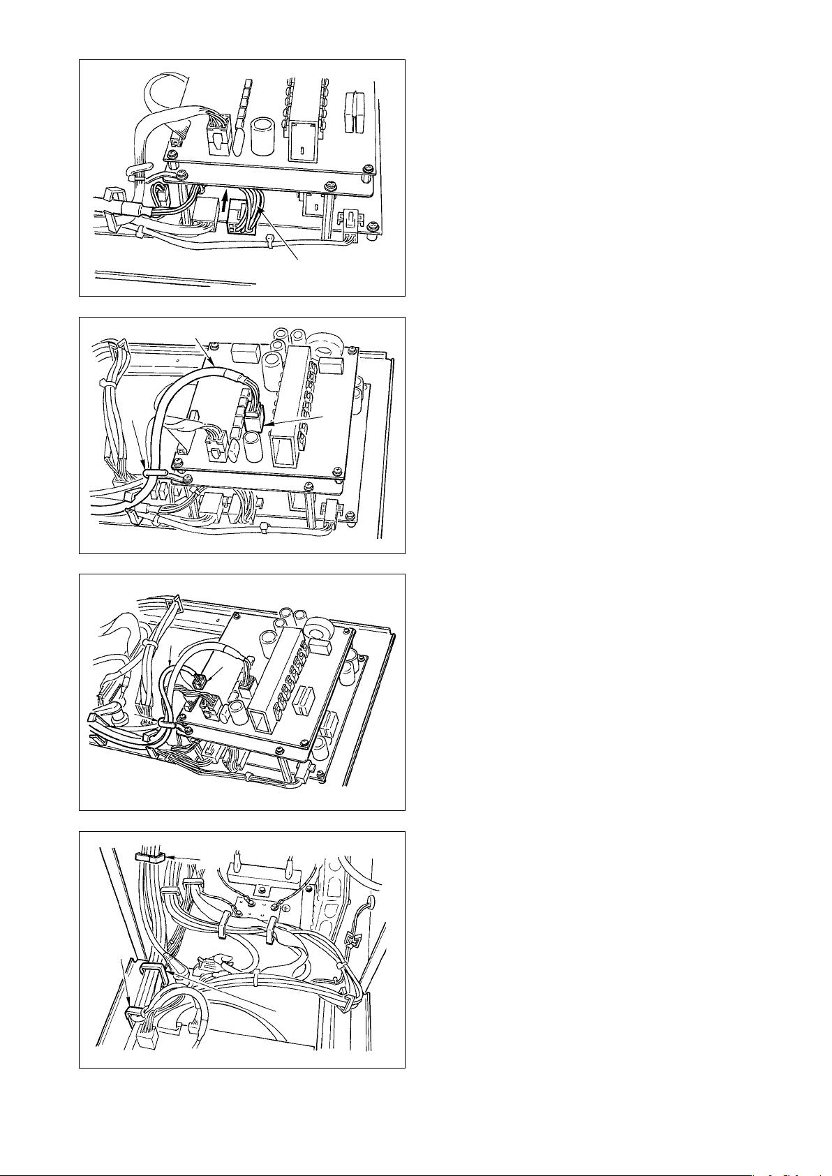
How to lock the cord clamp
When the insertion of the connector is completed,
lock the cord clamps.
4
Lightly press the corner of clamp.
4
(Cord clamp is locked with a click.)
2
C
1
B
A
[For CE territory]
4
3
Clamp
Take care so that the cord is not caught between
q
the rear cover and the electrical box main body,
close the rear cover while pressing section A on
the lower side of the rear cover, and tighten four
screws 1.
Press down cord presser plate C of cord through
w
hole B of the front cover, press the cord, and
tighten screws 2.
22) Install core clamp #5 supplied as accessories at
the position as shown in the gure.
#5
4-9. Attaching the connecting rod
3
2
1
B
A
1) Fix connecting rod 1 to installing hole B of pedal
lever 2 with nut 3.
2) Installing connecting rod 1 to installing hole A
will lengthen the pedal depressing stroke, and the
pedal operation at a medium speed will be easier.
Page 18
4-10. Adjustment of the pedal
2
1
3
4
Installing the connecting rod
1) Move pedal 3 to the right or left as illustrated by
the arrows so that motor control lever 1 and con-
necting rod 2 are straightened.
Adjusting the pedal angle
1) The pedal tilt can be freely adjusted by changing
the length of the connecting rod.
2) Loosen adjust screw
connecting rod
2
, and adjust the length of
4
.
4-11. Installing the thread stand
1) Assemble the thread stand unit, and insert it in
the hole in the machine table.
2
2) Tighten locknut
to x the thread stand.
1
3) For ceiling wiring, pass the power cord through
spool rest rod 2.
1
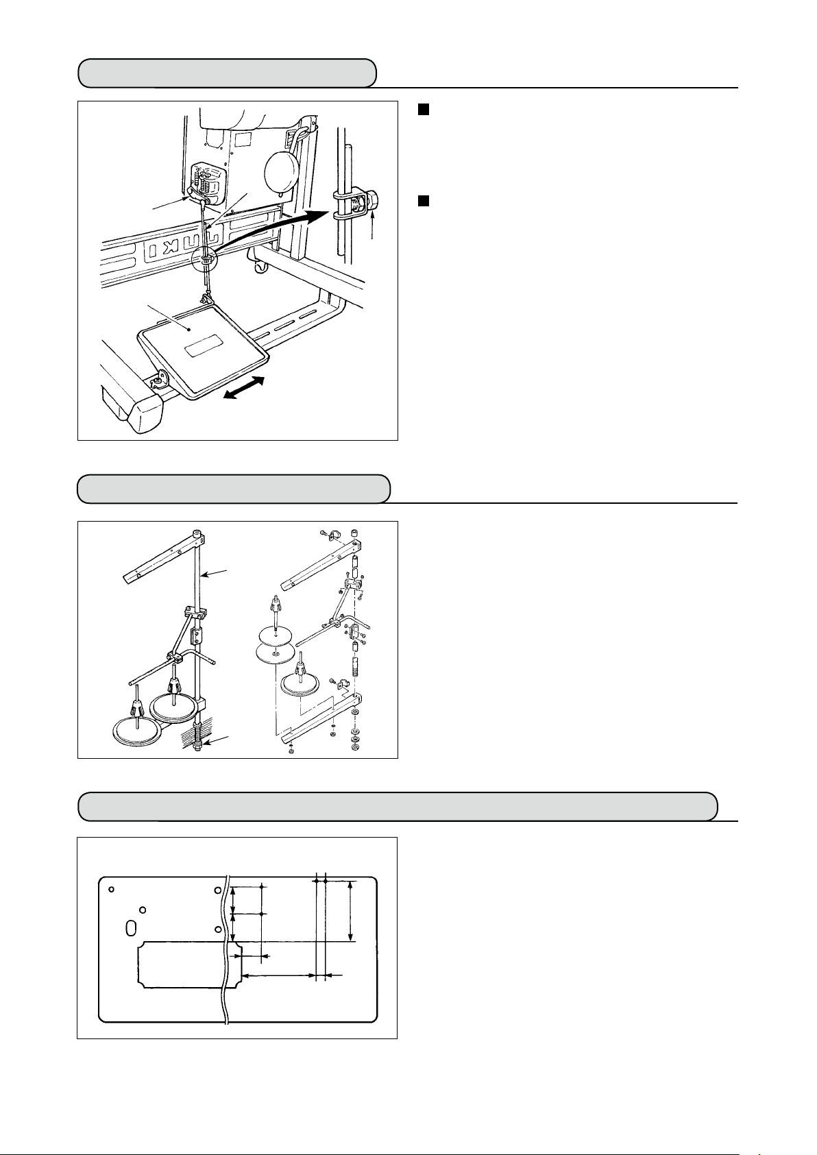
4-12. Installing the bird’s nest prevention (CB) type sewing machine
(bottom surface of the machine table)
(mm)
106 107
233
1) Punch dots on the positions of the setscrews of
solenoid valve (asm.) and regulator (asm.) on the
bottom surface of the machine table.
Besides, awling is performed on JUKI genuine
table.
75
291
34
– 15 –
Page 19
– 16 –
2
1
9
9
3
2) Fix solenoid valve (asm.) 1 with wood screws 2
supplied with the sewing machine as accessories.
4
3) Fix regulator (total asm.) 3 with wood screw 4
supplied with the sewing machine as accessories.
4) Connect ø6 and ø8 hoses attached to regulator
(total asm.) 3 to the respective solenoid valves.
5) Insert dust bag 5 into the top end of hose 9 for
dust bag and x it with band 6 supplied with the
sewing machine as accessories.
φ
φ
6
5
6
5
6) Adjust solenoid valve cord (asm.) 7 to the solenoid valve and the hot marker of the cord, and
connect it.
Connect 6P connector
to CM52 connector
!0!
1
inside the electrical box.(Refer to “When the bird’s
!0
4
nest prevention device is used, p. 13”.)
7) Connect air hose ø4 coming from the machine
head to the solenoid valve section and air hose
ø8 to the dust bag suction port respectively.
!1
8) Fix the solenoid valve and the air hose on the
table with staple 8 supplied as accessories.
8
1. Fix the staple to such an extent
that the air hose is not crushed.
2. Determine the position of the
staple so that the cord and the air
hose do not hang from the table.
7
8
!0
!1
!2
9) Connect the air pipe !2 and set the air pressure to
0.6 MPa.
• When air pressure is used under
the specied value, clamp trouble
will be caused.
Page 20
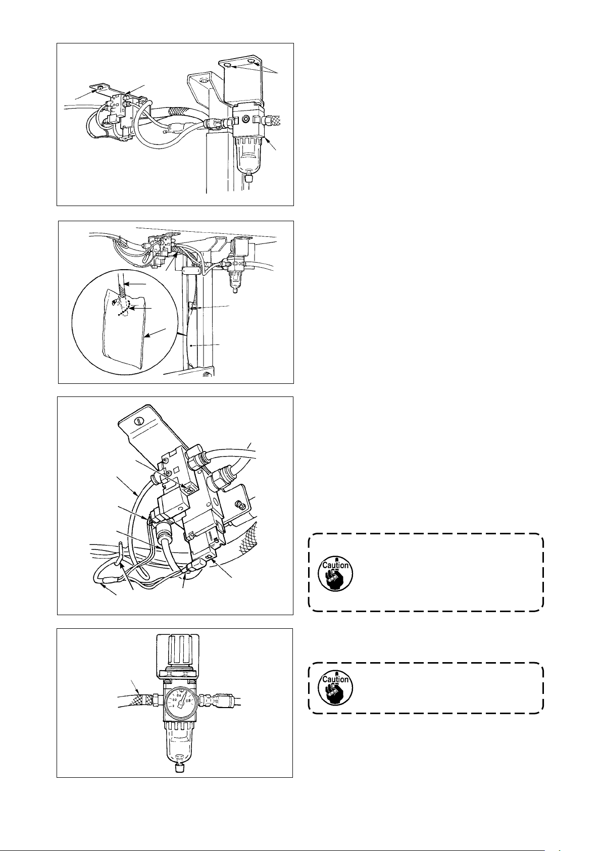
4-13. Lubrication
WARNING :
1. Do not connect the power plug until the lubrication has been completed so as to prevent accidents due to abrupt start of the sewing machine,
2. To prevent the occurrence of an inammation or rash, immediately wash the related portions if
oil adheres to your eyes or other parts of your body.
3. If oil is mistakenly swallowed, diarrhea or vomitting may occur. Put oil in a place where children
cannot reach.
1
2
3
2
Lower engraved
marker line
4
Upper engraved
marker line
Fill the oil tank with oil for hook lubrication before operating the sewing machine.
1) Remove oil hole cap 1 and ll the oil tank with
JUKI New Defrix Oil No. 1 using the oiler supplied
with the machine.
2) Fill the oil tank with oil up to the place where the
top of oil amount indicating rod 3 aligns with the
upper engraved line of oil amount indicating window 2.
If the oil is lled excessively, it will leak from the
air vent hole in the oil tank or proper lubrication
will be not performed. So, be careful.
3) When you operate the sewing machine, rell oil if
the top end of oil amount indicating rod 3 comes
down to the lower engraved marker line of oil
amount indicating window 2.
• When you use a new sewing machine or a sewing machine after
an extended period of disuse, run
your machine at 3,000 to 3,500 sti/
min for the purpose of break-in.
• For the oil for hook lubrication,
purchase JUKI New Defrix Oil No.
1 (Part No. : MDFRX1600C0).
• For oiling, perform with oiler
(B19210120A0) 4 supplied as
accessories. Be careful that dust
such as thread waste or the like is
not oiled when oiling.
– 17 –
Page 21
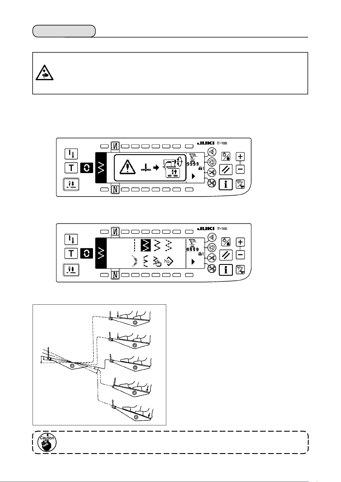
4-14. Test run
(1) Turn ON the power
WARNING :
• Check again the power voltage before connecting the power cord.
• Check that the power switch is turned OFF and connect the power cord to the power receptacle.
• Be sure to connect the earth wire.
• In case where the buzzer keeps beeping immediately after turning ON the power, there is a possibility of the wrong connection of cord or wrong power voltage. Turn OFF the power.
1) When the needle bar is in its UP position, zigzag origin detection is performed.
2) When the needle bar is in the position other than UP position :
Display as shown in the gure below appears. Turn the handwheel to bring the needle bar to needle UP
position and the display changes to the next screen. Then the needle moves left and right, and zigzag
origin detection is performed.
(2) How to operate the pedal
h
A
B
C
D
E
The pedal is operated in four stages.
1) Lightly depress the front part of the pedal for lowspeed operation B .
2) Further depress the front part of the pedal for
high-speed operation A . (Note that the sewing
machine will enter the high-speed operation mode
after the completion of reverse feed stitching if the
automatic reverse feed stitching function is speci-
ed with the corresponding switch.)
3) Bring the pedal back to its neutral position, and
the sewing machine will stop running C .
(The needle stops in the highest / lowest position.)
4) Strongly depress the back part of the pedal, and
the thread trimmer will be actuated E .
Lightly depress the back part of the pedal, and
the presser foot will go up D . Further depress
the back part of the pedal, and the thread trimmer
will be actuated.
One stitch only becomes soft start (approximately 200 sti/min) by pedal operation
immediately after turning ON the power.
– 18 –
Page 22
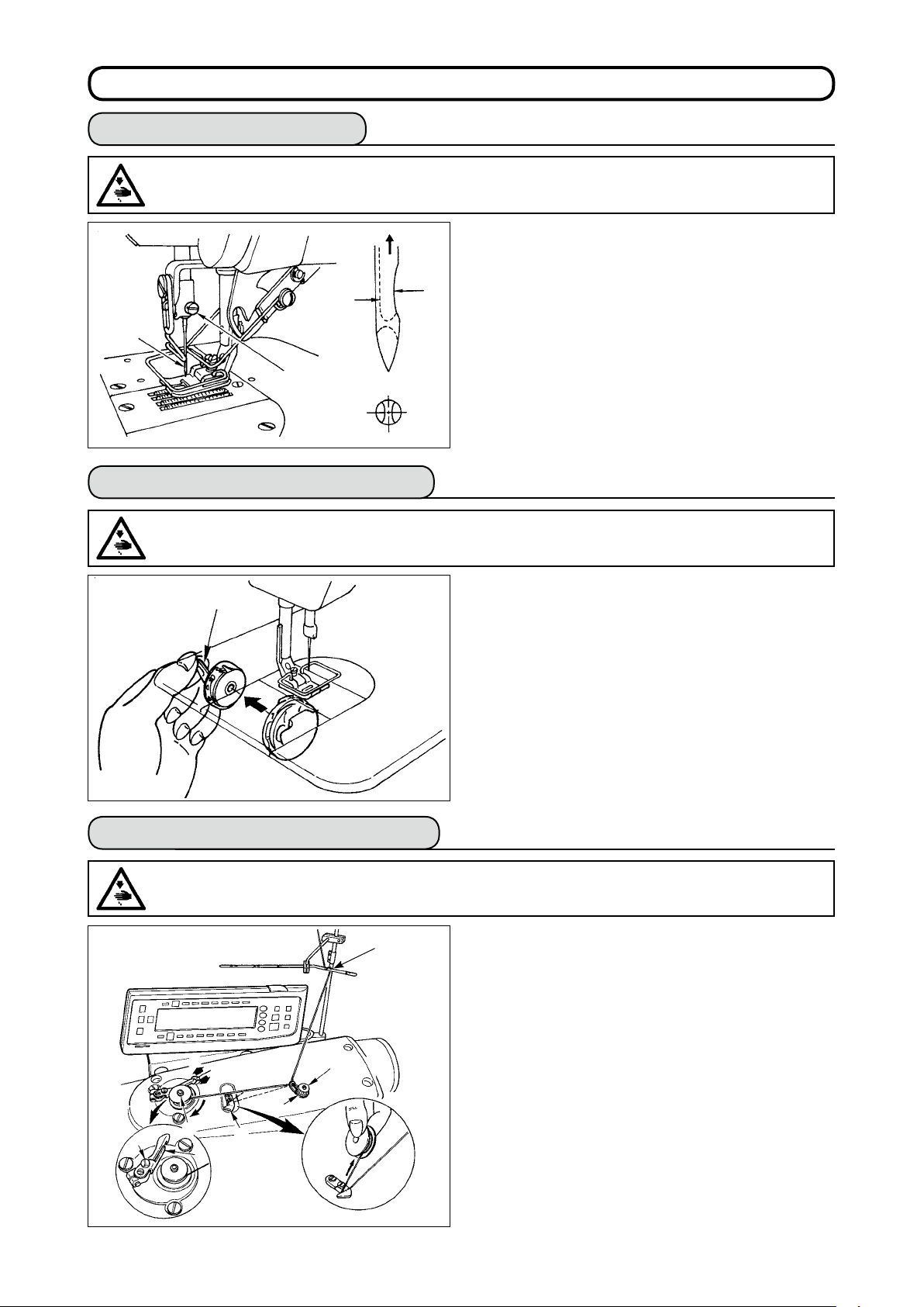
5. PREPARATIoN BEFoRE SEWING
5-1. Inserting the needle
WARNING :
To protect against possible personal injury due to abrupt start of the machine, be sure to start the
following work after turning the power off and ascertaining that the motor is at rest.
1) Turn the handwheel by hand to raise the needle
to its highest position.
B
A
1
2
5-2. Removing the bobbin case
WARNING :
To protect against possible personal injury due to abrupt start of the machine, be sure to start the
following work after turning the power off and ascertaining that the motor is at rest.
2) Loosen the needle clamp screw 2. Hold the needle 1 so that the long groove B on the needle is
facing exactly toward you.
3) Insert the needle deep into the hole of the needle
bar in the direction of the arrow until it will go no
further.
4) Securely tighten the screw 2 .
5) Confirm that the long groove B on the needle
faces toward you.
q
5-3. Winding the bobbin thread
WARNING :
To protect against possible personal injury due to abrupt start of the machine, be sure to start the
following work after turning the power off and ascertaining that the motor is at rest.
1
7
5
B
A
C
6
2
8
3
1) Turn the handwheel by hand to raise the needle
to its highest position.
2) Raise bobbin case latch 1 and remove the bobbin case.
1) Insert the bobbin deep into the bobbin winder spindle 5 until it will go no further.
2) Pass the bobbin thread pulled out from the spool rested
on the right side of the thread stand following the order
from 1 as shown in the gure on the left. Then, wind the
end of the bobbin thread on the bobbin several times.
3) Press the bobbin winder adjusting plate 6 in the direction of A and start the sewing machine. The bobbin
rotates in the direction of C and the bobbin thread is
wound up. The bobbin winder spindle 5 will auto-
matically stop as soon as the winding is nished.
4) Remove the bobbin and cut the bobbin thread with
the thread cut retainer 8 .
5) To adjust the winding amount of the bobbin thread,
loosen setscrew 7 and move bobbin winder adjusting plate 6 to the direction of A or B. Then, tighten
setscrew 7.
To the direction A : The amount is decreased.
To the direction B : The amount is increased.
– 19 –
Page 23
– 20 –
(Threading)
1
w
6) In case that the bobbin thread is not wound evenly on the bobbin, loosen the nut 4 and turn the
bobbin thread tension to adjust the height of the
thread tension disk 2.
A
w
r
• It is the standard that the center of the bobbin is
as high as the center of the thread tension disk.
• Move the position of the thread tension disk 2 to
the direction A as shown in the gure on the left
B
w
when the winding amount of the bobbin thread on
the lower part of the bobbin is excessive and to
the direction B as shown in the gure on the left
when the winding amount of the bobbin thread on
the upper part of the bobbin is excessive.
After the adjustment, tighten the nut 4 .
7) Turn the thread tension nut 3 to adjust the tension of the bobbin thread winder.
Note 1. When winding bobbin thread, start winding
3
2. When winding bobbin thread in the state that
2
in the state that the thread between bobbin
and thread tension disk 2 is tense.
the sewing is not performed, remove needle
thread from the thread path of the thread
take-up and remove bobbin from the hook.
5-4. Placing the bobbin case and the bobbin
WARNING :
To protect against possible personal injury due to abrupt start of the machine, be sure to start the
following work after turning the power off and ascertaining that the motor is at rest.
1) Turn the handwheel by hand to raise the needle
to its highest position.
2) Take a bobbin by your right hand with the thread
drawn out about 5 cm from the thread end of the bobbin and place it into the bobbin case as illustrated.
3) Thread the bobbin case in the order of the numbers and pull it out through the thread path as illustrated. The bobbin rotates in the bobbin case in
the direction shown by arrow when bobbin thread
is drawn.
4) Raise bobbin case latch 1 and hold it between
your two ngers as shown in the gure on the left.
5) Insert the bobbin case into the sewing hook shaft
as far as it will go by putting your hand from the
under cover of the inner hook. (Click sounds.)
6) Release the bobbin case latch to let it steadily
rest in the closing position.
How to use the bobbin case thread hole
1) Use hole A mainly for zigzag stitches other than
2-step zigzag stitch and scallop zigzag stitch.
2) Use hole B mainly for 2-step zigzag stitch and
scallop zigzag stitch.
q
e
w
q
B
A
There may be a case where several stitches at the start of sewing are difcult to be knotted when
thread trimmer is used with thin lament thread such as (#50, #60 or #80) using hole B. At this
time, use the other hole or perform the sewing starting from the right.
Page 24
5-5. Threading the machine head
WARNING :
To protect against possible personal injury due to abrupt start of the machine, be sure to start the
following work after turning the power off and ascertaining that the motor is at rest.
5
1
2
3
4
6
1) Turn the handwheel by hand to bring the needle to the most raised position.
2) Pass the thread in the order of the numbers as illustrated.
3)
Pull out the thread about 10 cm from the needle after passing it through the needle.
5-6. Adjusting the stitch length
1)
Adjustment of the stitch length is performed with the operation panel.
For the setting procedure of the respective sewing patterns, refer to “6-5.
Setting the sewing pattern”.
Normal feed : Press +/– keys of to input.
Reverse feed : Press +/– keys of to input.
2) Numerical value of the operation panel is indicated in mm.
1
There may be the cases where the feed amount of the operation panel and the actual sewing pitch are different from each other in case of the use in the state other than the standard delivery or material used. Compensate the pitch in accordance with the sewing product.
3) When performing the reverse feed stitching, press down reverse feed
control lever 1. The sewing machine performs reverse feed stitching as
long as you keep the lever held pressed. The reverse feed control lever
will return to its home position and the sewing machine will run in the normal stitching direction when you release the reverse feed control lever.
Example) In case of normal feed :
the sewing range becomes normal feed +4 to –3. The maximum amount
of reverse feed becomes –3 when reverse feed control lever 1 is
pressed. Besides, it is possible to adjust the stitch length of normal/reverse feed up to 5 mm at the maximum by inputting.
+4 and reverse feed :
Turn the thread
once.
–3,
5-7. Adjusting the condensation stitching
Condensation stitching means that feed pitch amount is reduced and tie
stitching is performed by operating the reverse feed control lever at the
start or end of sewing.
1) Adjustment of the stitch length is performed with the operation panel.
Reverse feed : Press +/– keys of to input. Tie stitching can be per-
formed by inputting the reverse feed amount to “0”.
2) Note that the tie stitching value is mere reference. Adjust the condensa-
tion stitching while actually observing the nished seam.
3) Numerical value of the operation panel is indicated in mm.
It is possible for the gauge delivered (feed dog part No. : 40018430) to adjust
up to 5 mm of normal/reverse feed at the maximum. There is a possibility that
material is apt to fall in case of the process where the feed amount is small.
Use the gauges such as feed dog and the like in accordance with the process.
– 21 –
Page 25
– 22 –
6. HoW To uSE THE oPERATIoN PANEL
6-1. Names and functions of the respective sections
!7
1 4 5
2
3
!7
Re-sewing switch
1
Teaching switch
2
Needle up/down compensating switch
3
Screen changeover switch
4
With/without reverse feed stitch at sewing start switch
5
With/without reverse feed stitch at sewing end switch
6
Material edge sensor switch
7
One-shot automatic sewing switch
8
With/without automatic thread trimmer switch
9
7
8
96
Thread trimming prohibiting switch
!0
Backlight switch
!1
Reset switch
!2
Information switch
!3
+ switch
!4
– switch
!5
Counter/speed changeover switch
!6
General-purpose switch
!7
Power display lamp
!8
!1 !2 !4 !5
!8
!6!3!0
Switch Description
Re-sewing switch This switch is used to continue sewing from the step on the
1
Teaching switch This is the switch to set the setting of the number of stitches
2
Needle up/down compensating switch
3
Screen changeover switch
4
With/without reverse feed
stitch at sewing start switch
5
way after replacing bobbin thread when bobbin thread has
run out during program stitching step.
with the value of number of stitches which has been actually sewn.
This is the switch to perform needle up/down compensating
stitching. (Needle up/down compensating stitching and one
stitch compensating stitching can be changed over with function
setting No. 22.)
This is the switch to change over the screen.
This is the switch to turn ON/OFF automatic reverse feed
stitch at sewing start.
* This switch cannot be used with the sewing machine
which is not provided with automatic reverse feed stitching device.
Page 26
Switch Description
With/without reverse feed
stitch at sewing end switch
❻
Edge sensor switch
❼
One-shot automatic sewing
switch
❽
With/without automatic
thread trimmer switch
❾
Thread trimming prohibiting
switch
Backlight switch
This is the switch to turn ON/OFF automatic reverse feed
stitch at sewing end.
* This switch cannot be used with the sewing machine
which is not provided with automatic reverse feed stitching device.
Selects use/disuse of the material edge sensor in the case
the material edge sensor (edge) is installed on the sewing
machine.
When this switch is pressed, the sewing machine automat-
ically operates until the material edge sensor detects the
material edge or until the set number of stitches is reached.
This switch is used to automatically trim the thread when
the material edge sensor detects the material edge or until
the set number of stitches is reached.
* This switch cannot be used with the sewing machine
which is not provided with the automatic thread trimming
device.
This switch prohibits all thread trimmings.
* This switch cannot be used with the sewing machine
which is not provided with the automatic thread trimming
device.
This switch is used to change over the operation of the
backlight of the LCD between ON and OFF.
Reset switch
Information switch
Plus switch
Minus switch
Counter/speed changeover
switch
General-purpose switch
Power display lamp This lamp lights up when the power switch is turned ON.
This is the switch to make the value of bobbin thread count-
er or sewing counter the set value. This switch is enabled
after thread trimming.
This switch is used to change over the screen between the
information function screen (sewing common data mode,
function setting mode, communication mode, version dis-
play, etc.) and the normal sewing screen.
This switch is enabled after thread trimming.
This switch is used to increase the set value of the bobbin
thread counter or the number of pcs. counter at the time of
setting. It should be remembered that this switch is enabled
after thread trimming.
This switch is used to decrease the set value of the bobbin
thread counter or the number of pcs. counter at the time of
setting. It should be remembered that this switch is enabled
after thread trimming.
This switch is used to change over the display between the
counter display and the maximum sewing speed limitation
display.
This switch has different functions depending on the
screen.
– 23 –
Page 27
– 24 –
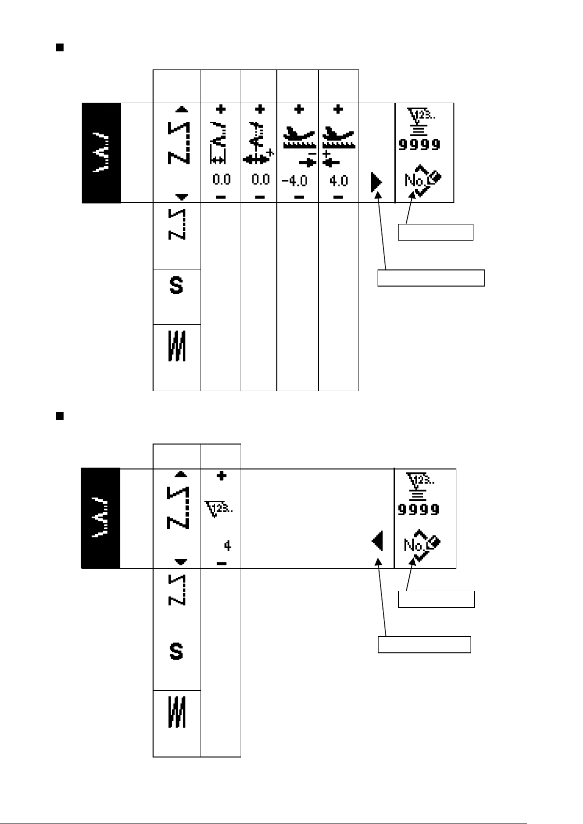
6-2. Before setting the pattern
WARNING :
• When using presser foot, throat plate and feed dog other than those delivered
as standard, needle may come in contact with throat plate and breaks, or feed
dog may come in contact with throat plate in case of some set values. Be sure
to perform the regulation of limitation values of 1, 3 and 4 in accordance with
the gauge used. The regulation at the time of delivery is as follows :
Max. zigzag width : 8 mm
Max. feed amount : 5 mm
• When replacing the gauge, provide a clearance of 0.6 mm or more between
needle, and presser foot and throat plate, and between throat plate and feed dog.
(1) Limitation of the max. zigzag width
Max. zigzag width limitation value, reference of stitch base line, normal feed amount limitation
1 2 3 4
• Max. zigzag width can be limited in accordance with the gauge.
• There are two kinds of limitations of max. zigzag width.
(1) Zigzag width symmetrical in the center
(2) Specifying left/right positions
value and reverse feed amount limitation value are displayed when the power is turned ON.
:
Max. zigzag width limitation value (Screen changes in case of specifying left/right positions.)
1
: Reference of stitch base line
2
: Max. reverse feed amount limitation value
3
: Max. normal feed amount limitation value
4
Display of max. zigzag width limitation value, reference of stitch base line, normal feed
amount limitation value and reverse feed amount limitation value can be performed
with ON/OFF.
0.6
0.6
0.6
Changeover of limiting procedure of max. zigzag width limitation value
1) Press switch 1.
q
2) Press switch 2.
w
e
3) Figure on the left side is
the zigzag width symmet-
rical in the center mode.
Every time switch 3 is
pressed, specifying left/
right positions and zigzag
width symmetrical in the
center can be changed
e
over alternately.
⇔
(1) Zigzag width symmetrical in the center
(2) Specifying left/right positions
Page 28
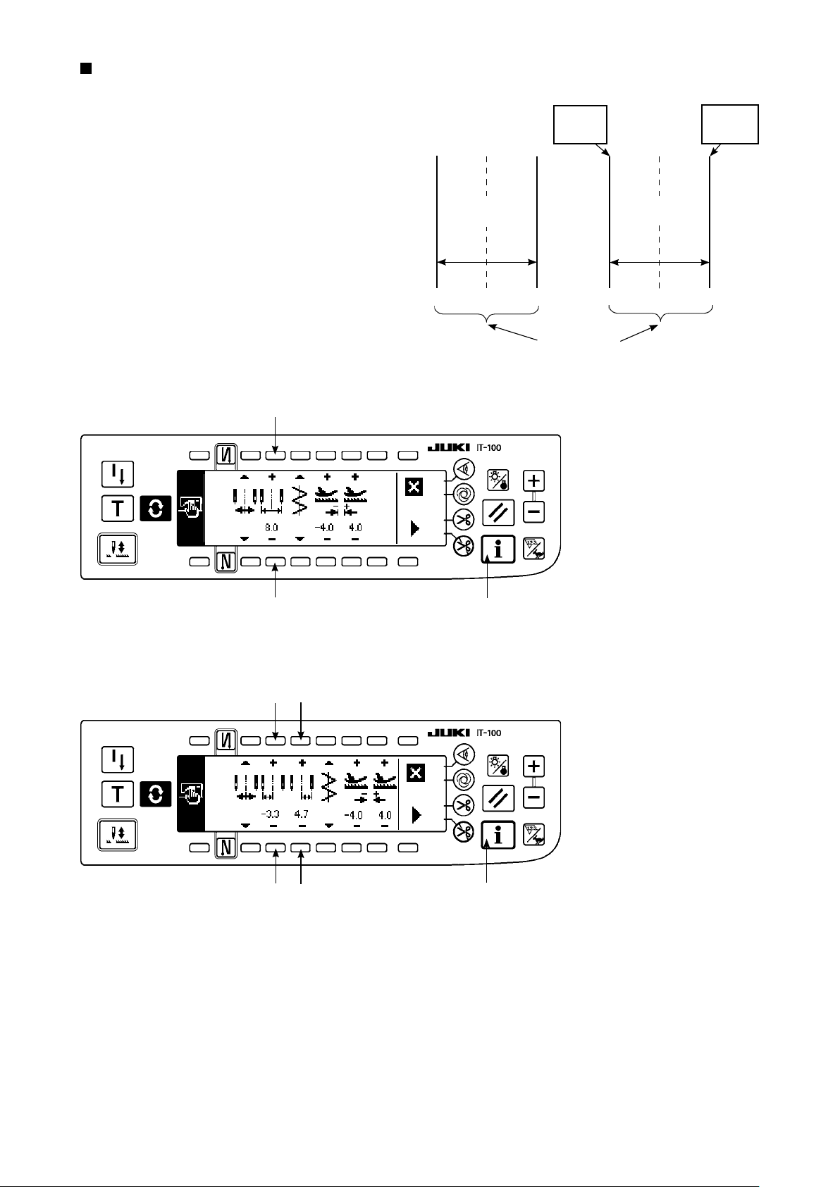
How to set max. zigzag width limitation value
Determine whether limitation of zigzag width sym-
metrical in the center or limitation of left/right posi-
tions in the order of 1) to 3) of the previous page in
accordance with the gauge used.
Limitation of zigzag
width symmetrical
in the center
0.0 0.0
L = -3.3
Setting
Limitation
of left/right
positions
R = +4.7
Setting
–4.0 +4.0
(A) In case of zigzag width symmetrical in the center
4
4
M a x . z i g z ag
width limitation
value
8.0
1
M a x . z i g za g
width limitation
value
8.0
–3.3 +4.7
Zigzag
limitation area
1) Press +/– of switch 4 and
set the limitation value.
In case of the example, set
the value to 8.0.
2) Press switch 1 and the
screen returns to the pre-
vious one.
(B) In case of specifying left/right positions
6
5
6
5
1
Change of left side posi-
tion limitation
1) Press +/– of switch 5 to
set the left side limitation
value.
In case of the example, set
the value to -3.3.
Change of right side posi-
tion limitation
2) Press +/– of switch 6 to
set the right side limitation
value.
In case of the example, set
the value to +4.7.
3) Press switch 1 and the
screen returns to the pre-
vious one.
– 25 –
Page 29
– 26 –
(2) Setting the reference of stitch base line
• Reference position of stitch base line can be set to left, center and right.
Reference of left
stitch base line
Reference of center
stitch base line
Reference of right
stitch base line
How to set
0.0 0.0
2
3
0.0
1) Press switch 1.
1
2) Press switch 2.
Reference of left
stitch base line
3
Reference of center
stitch base line
1
Reference of right
stitch base line
3) Figure on the left side
shows the reference of
center stitch base line.
Every time switch 3 is
pressed, reference of left
stitch base line, that of
right stitch base line and
that of center stitch base
line are changed over and
set alternately.
4) Press switch 1 and the
screen returns to the previous one.
Page 30
(3) Setting the feed amount
• Max. possible setting range in the normal direction and max. possible setting range in the reverse direction can be set in accordance with the gauge used.
Setting procedure
2
1
Change in the reverse
direction
1) Press +/– of switch 1 to
set the limitation value in
the reverse direction.
In case of the example, the
feed amount is –3.6.
2
1
Level of the standard delivery of key lock is “1”. To perform all settings, it is necessary to set the
key lock to level “0”. For the details, see p.102.
3
Change in the normal
direction
2) Press +/– of switch 2 to
set the limitation value in
the normal direction.
In case of the example, the
feed amount is +4.8.
3) When switch 3 is pressed,
the screen returns to the
previous one.
– 27 –
Page 31

– 28 –
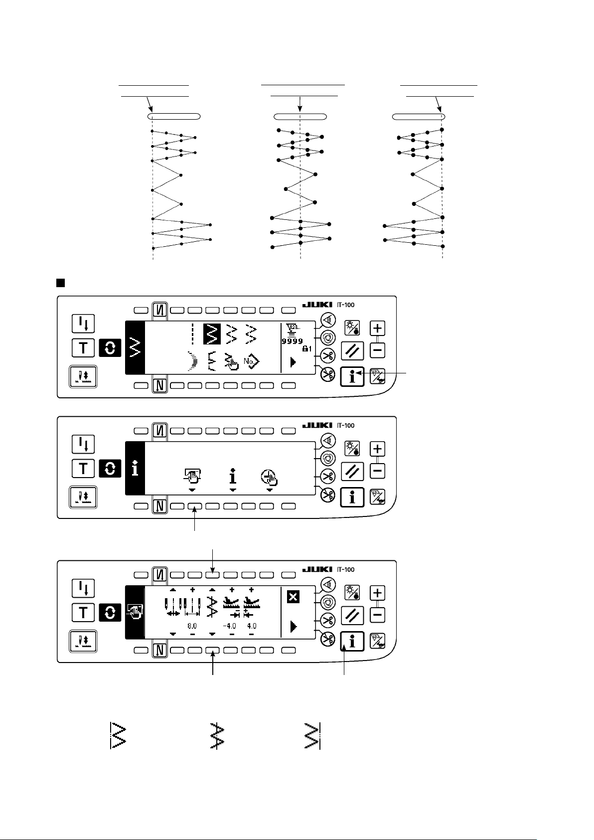
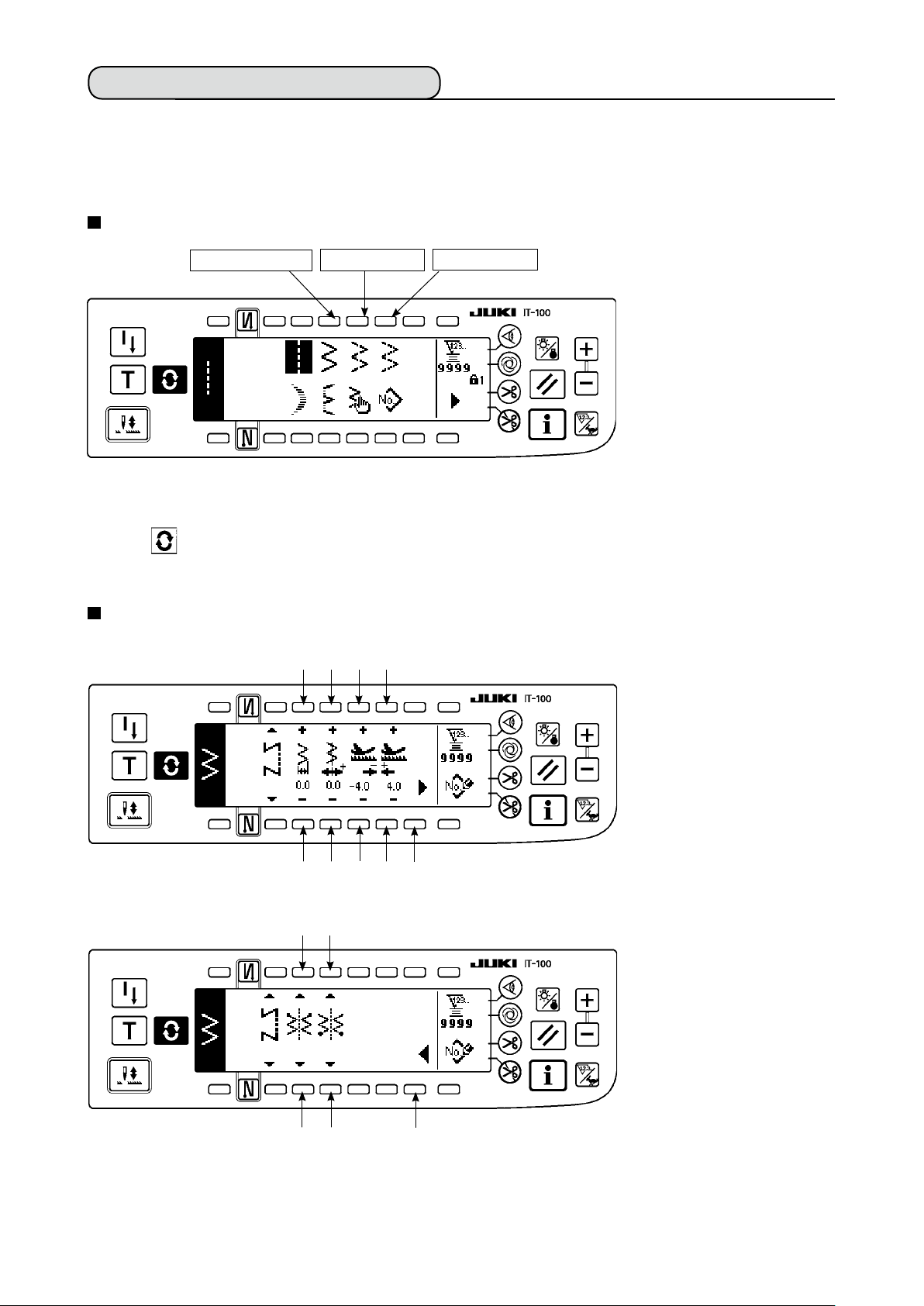
6-3. Basic screen
The screen after turning ON the power source becomes the screen at the time of turning OFF the power
source for the last time.
Every time switch is pressed, the screen changes as follows :
Example) Free stitching of 2-step zigzag with reverse feed stitching (Contents of display change depending
on the set values.)
Sewing shape list rst screen
Selection of each shape is
performed.
Press .
* Free stitching means the
general sewing.
Press s.
Press t .
Sewing shape list second screen
Sewing shape setting rst
screen
Press s.
Press t .
Sewing shape setting second
Press .
Reverse feed stitching setting screen
Setting of kind of condensation, number of stitches, etc. is performed.
screen
Press .
When is pressed for approximately three seconds in a screen other than the sewing shape
list screen, the screen directly transits to the sewing shape list screen.
Page 32

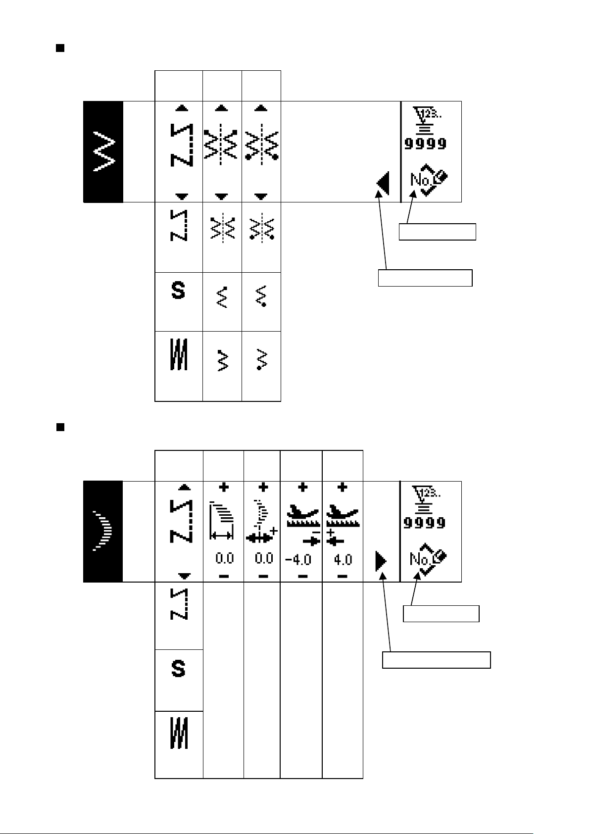
6-4. List of the display pictographs of each screen
Sewing shape list rst screen
Straight stitch
Scallop Custom Pattern
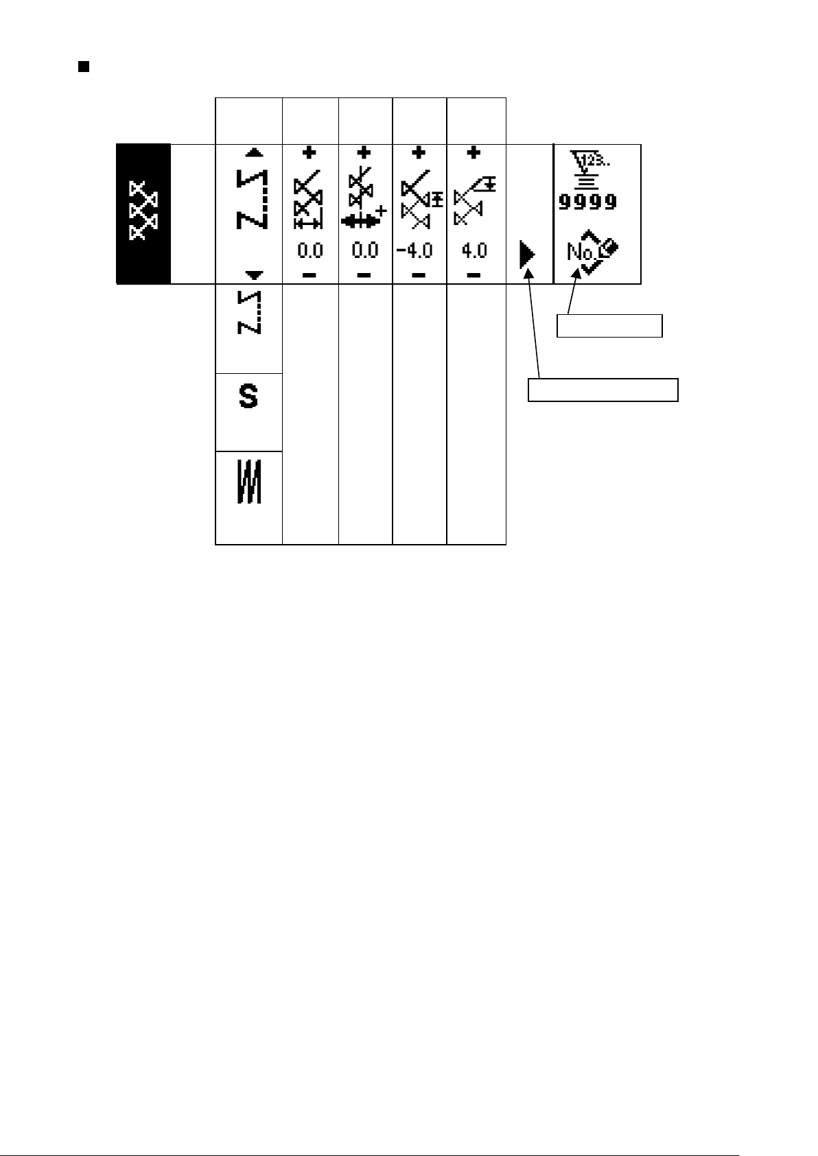
Sewing shape list second screen
Continuous stitching T stitch, left
2-step zigzag stitch
Blind stitch
3-step zigzag stitch
Pattern 1T stitch, right
4-step zigzag stitch
Cycle stitching Pattern 3 Pattern 4
Scallop selection pop-up screen
Pattern 2
(Fagoting)
Left equal 12 stitchesLeft equal 24 stitchesLeft standard Left crescent
Left equal 12 stitchesLeft equal 24 stitchesRight standard Right crescent
– 29 –
Page 33

– 30 –
Blind stitch selection pop-up screen
Left blind stitch Right blind stitch
Custom pattern selection pop-up screen
Pattern stitching selection pop-up
Custom pattern new creation
Continuous stitching selection pop-up screen
Cycle stitching selection pop-up screen
Cycle stitching new creation
Continuous stitching new creation
The key lock level has been set to "1" at the time of delivery, and pictographs of new creation are not displayed. When performing new creation in each mode, change the key lock level to "0". (Refer to the second
screen of sewing common data setting of (1) Sewing common data of 6-16. Information. )
In addition, the display of pattern No. at the time of delivery is "1" only.
Page 34

Straight stitch sewing shape setting screen
Kind of sew-
ing
Free
stitching
Programmed
stitching
Position
of stitch
base line
−5.0
to
5.0
Reverse
feed
amount
−5.0
to
5.0
Normal
feed
amount
Pattern register
−5.0
to
5.0
Overlapped
stitching
2-step zigzag, 3-step zigzag, and 4-stap zigzag stitch sewing shape rst screen
Kind of sew-
ing
Zigzag
width
Position
of stitch
base line
Reverse
feed
amount
Normal
feed
amount
Pattern register
Free
stitching
Programmed
stitching
0
to
10.0
−5.0
to
5.0
−5.0
to
5.0
−5.0
to
5.0
Second screen display
Overlapped
stitching
– 31 –
Page 35
– 32 –
2-step zigzag, 3-step zigzag, and 4-stap zigzag stitch sewing shape second screen
Kind of
sewing
Free
stitching
Programmed
stitching
Position
at sewing
start
Optional Optional
Right
Position
at sewing
end
Right
Pattern register
First screen display
Overlapped
stitching
Scallop sewing shape setting rst screen
Kind of sew-
ing
Free
stitching
Programmed
stitching
Left
Zigzag
width
0
to
10.0
Left
Position
of stitch
base line
−5.0
to
5.0
Reverse
feed
amount
−5.0
to
5.0
Normal
feed
amount
−5.0
to
5.0
Pattern register
Second screen display
Overlapped
stitching
Page 36

Scallop sewing shape setting second screen
Kind of
sewing
Free
stitching
Programmed
stitching
Position
at sewing
start
Root •
Crest
Root
Crest Root
Position
at sewing
end
Right •
Left
Optional
Stop posi-
Optional
tion
Pattern register
Overlapped
stitching
Right
Left
* Stop position is displayed when the position at sewing end is optional.
– 33 –
Page 37
– 34 –
Blind stitch sewing shape setting rst screen
Kind of sew-
ing
Free
stitching
Programmed
stitching
Zigzag
width
0
to
10.0
Position
of stitch
base line
−5.0
to
5.0
Reverse
feed
amount
−5.0
to
5.0
Normal
feed
amount
−5.0
to
5.0
Pattern register
Second screen display
Overlapped
stitching
Blind stitch sewing shape setting second screen
Kind of sew-
ing
Free
stitching
Programmed
stitching
Number of
stitches
3
to
250
Pattern register
First screen display
Overlapped
stitching
Page 38

T stitch, left sewing shape setting rst screen
Kind of sew-
ing
Free
stitching
Programmed
stitching
Zigzag
width
0
to
10.0
Position
of stitch
base line
−5.0
to
5.0
Compensation
value
−5.0
to
5.0
Normal
feed
amount
−5.0
to
5.0
Pattern register
Second screen display
Overlapped
stitching
T stitch, left sewing shape setting second screen
Kind of sew-
ing
Free
stitching
Programmed
stitching
Position
at sewing
start
Left Left
Right 1 Right 1
Position
at sewing
end
Pattern register
Overlapped
stitching
Right 2 Right 2
Optional Optional
– 35 –
Page 39

– 36 –
T stitch, right sewing shape setting rst screen
Kind of sew-
ing
Free
stitching
Programmed
stitching
Zigzag
width
0
to
10.0
Position
of stitch
base line
−5.0
to
5.0
Compensation
value
−5.0
to
5.0
Normal
feed
amount
−5.0
to
5.0
Pattern register
Second screen display
Overlapped
stitching
T stitch, right sewing shape setting second screen
Kind of sew-
ing
Free
stitching
Programmed
stitching
Position
at sewing
start
Right 1 Right 1
Left 1
Position
at sewing
end
Left 1
Pattern register
Overlapped
stitching
Right 2
Optional Optional
Right 2
Page 40

Pattern 1 sewing shape setting rst screen
Kind of sew-
ing
Free
stitching
Programmed
stitching
Zigzag
width
0
to
10.0
Position
of stitch
base line
−5.0
to
5.0
Compensation
value
−5.0
to
5.0
Normal
feed
amount
−5.0
to
5.0
Pattern register
Second screen display
Overlapped
stitching
– 37 –
Page 41

– 38 –
Pattern 1 sewing shape setting second screen
Kind of sew-
ing
Free
stitching
Programmed
stitching
Position
at sewing
start
Center 1 Center 1
Center 2
Position
at sewing
end
Center 2
Pattern register
Overlapped
stitching
Left
Center 3
Right
Optional
Left
Center 3
Right
Optional
Page 42

Pattern 2 (fagoting) sewing shape setting rst screen
Kind of sew-
ing
Free
stitching
Programmed
stitching
Zigzag
width
0
to
10.0
Position
of stitch
base line
−5.0
to
5.0
Reverse
feed
amount
−5.0
to
5.0
Normal
feed
amount
−5.0
to
5.0
Pattern register
Second screen display
Overlapped
stitching
– 39 –
Page 43

– 40 –
Pattern 2 sewing shape setting second screen
Kind of sew-
ing
Free
stitching
Programmed
stitching
Position
at sewing
start
Right 1 Right 1
Center 1
Position
at sewing
end
Center 1
Pattern register
Overlapped
stitching
Left1
Left2
Center 2
Right 2
Optional
Left1
Left2
Center 2
Right 2
Optional
* Position at the sewing start is set with ▲/▼ of switch 6.
Page 44
Pattern 3 sewing shape setting rst screen
Kind of sew-
ing
Free
stitching
Programmed
stitching
Zigzag
width
0
to
10.0
Position
of stitch
base line
−5.0
to
5.0
Reverse
feed
amount
−5.0
to
5.0
Normal
feed
amount
−5.0
to
5.0
Pattern register
Second screen display
Overlapped
stitching
– 41 –
Page 45

– 42 –
Pattern 3 sewing shape setting second screen
Kind of sew-
ing
Free
stitching
Programmed
stitching
Position
at sewing
start
Right 1 Right 1
Center 1
Position
at sewing
end
Center 1
Pattern register
Overlapped
stitching
Left1
Left2
Center 2
Right 2
Optional
Left1
Left2
Center 2
Right 2
Optional
Page 46

Pattern 4 sewing shape setting rst screen
Kind of sew-
ing
Free
stitching
Programmed
stitching
Zigzag
width
0
to
10.0
Position
of stitch
base line
−5.0
to
5.0
Reverse
feed
amount
−5.0
to
5.0
Normal
feed
amount
−5.0
to
5.0
Pattern register
Second screen display
Overlapped
stitching
– 43 –
Page 47

– 44 –
Pattern 4 sewing shape setting second screen
Kind of
sewing
Free
stitching
Programmed
stitching
Position
at sewing
start
Left1
Left2
Position
at sewing
end
Pattern register
Left1
Left2
Overlapped
stitching
Right 1
Right 2
Right 3
Left3
Optional
Right 1
Right 2
Right 3
Left3
Optional
Page 48
Custom pattern sewing shape setting screen
Kind of sew-
ing
Zigzag
width
Position
of stitch
base line
Custom Pattern
needle entry image
Free
stitching
Programmed
stitching
Overlapped
stitching
Custom pattern edit screen
Step
0
to
10.0
Zigzag
position
input
−5.0
to
5.0
Feed
amount
per stitch
Edit screen
display
Changeover of to-
tal display and en-
largement display
of custom pattern
Custom pattern
needle entry image
Pattern register
Copy, and dele-
tion screen
Pattern register
Copy
Deletion
Last needle entry input
1
to
500
−5.0
to
5.0
−5.0
to
5.0
Needle entry
point insertion
– 45 –
Determination
Needle entry
point deletion
Page 49

– 46 –
Pattern sewing shape setting screen
Sewing
shape
Selection of
sewing shape
Straight stitch
2-step zigzag stitch
3-step zigzag stitch
4-step zigzag stitch
Scallop
(8 kinds)
Blind stitch
(Right and Left)
Custom pattern
T stitch, left
T stitch, right
Pattern 1
Pattern 2
Pattern 3
Pattern 4
Display of contents depends on shape.
Refer to each shape.
Copy and
deletion screen
Copy
Deletion
Continuous stitching setting screen
Zigzag
width
0.0
10.0
Position
of stitch
base line
−5.0
to
to
5.0
Step
1
to
20
Pattern
No.
Number
of stitches
Edit screen display Copy and
deletion screen
Copy
Deletion
Page 50
Continuous stitching edit screen
Step
1
Pattern
No.
Sewing
shape
1
Number
of stitches
1
Determination
to
500
20
to
to
99
* For the sewing shape, the shape which has been registered in the pattern is displayed.
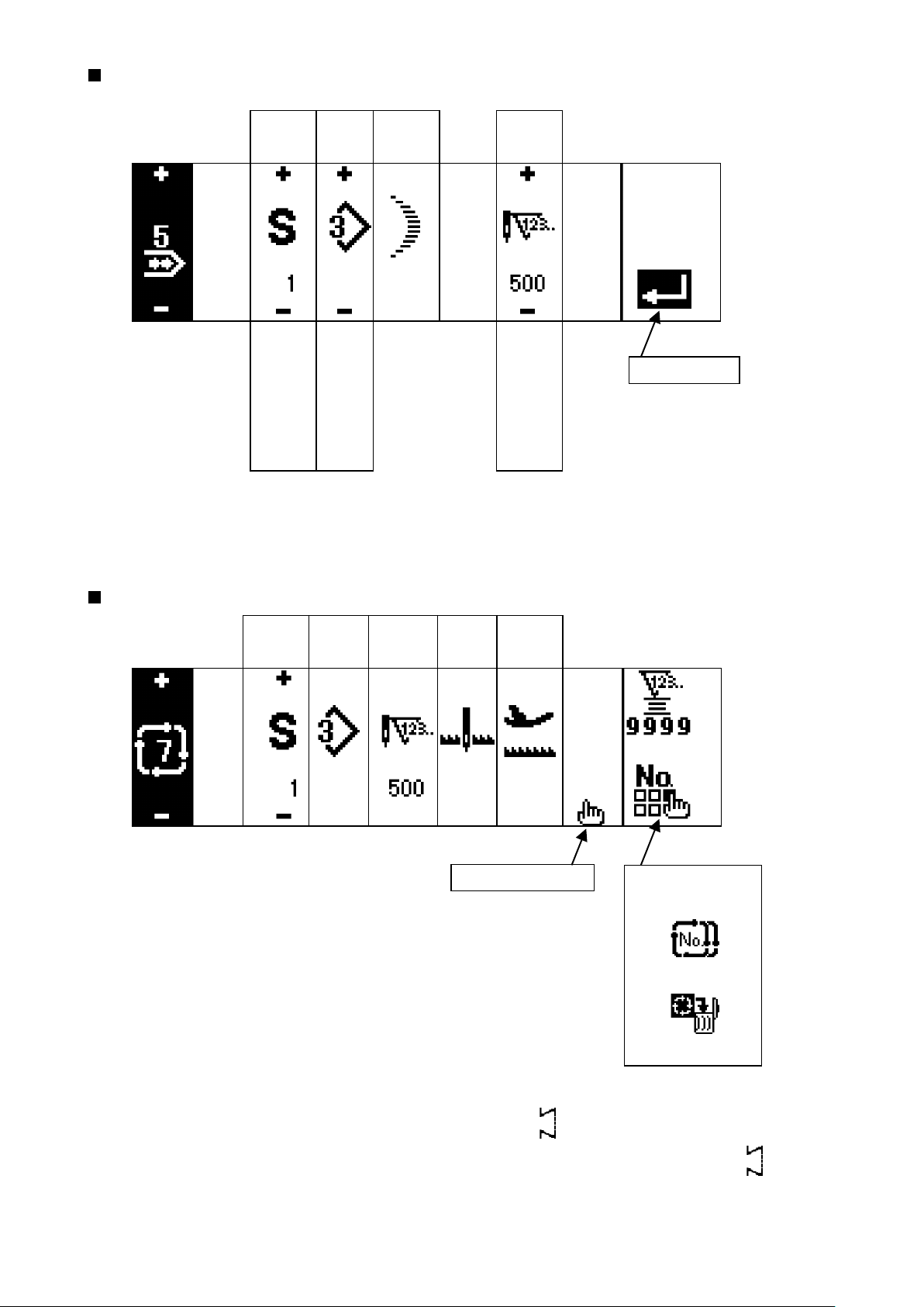
Cycle stitching setting screen
Step
Pattern
No.
Number
of stitches
Position
Stop state
of presser
foot
Edit screen display
Copy and
deletion screen
Copy
Deletion
* Stop state is not displayed when the number of stitches is (0 stitch).
* Position of presser foot is displayed except the case where the number of stitches is (0 stitch)
with the auto-lifter.
* Presser lifting time is displayed when the position of presser foot is UP stop.
– 47 –
Page 51
– 48 –
Cycle stitching edit screen
Step
1
to
20
Pattern
No.
1
to
*
Number
of stitches
(0 stitch)
to
500
Stop
state
Needle
DOWN
stop
Thread
trimming
Position
of presser
foot
Presser
foot UP
stop
Presser
foot
DOWN
stop
Presser
lifting time
Determination
0.1
to
99.9
Needle
UP stop
* Stop state is not displayed when the number of stitches is (0 stitch).
* Position of presser foot is displayed except the case where the number of stitches is (0 stitch)
with the auto-lifter.
* Presser lifting time is displayed when the position of presser foot is UP stop.
Page 52

Reverse stitching setting rst screen
Reverse
stitching
at sewing
start With/
without
Reverse
stitching
at sewing
end With/
without
Sewing start Sewing end
Selection
of kind
Normal 0 to 19 0 to 19 Normal 0 to 19 0 to 19
ProcessAProcessBSelection
of kind
ProcessCProcess
D
Custom Custom
2-point 0 to 19 0 to 19 2-point 0 to 19 0 to 19
Reverse stitching setting second screen (2-point condensation)
Width ad-
justment at
sewing start
Width
adjustment
at sewing
end
Reverse
Feed
amount
Max. sewing
speed
0.0
to
−5.0
0.0
to
−5.0
−5.0
to
5.0
200
to
5,000
* Feed amount is displayed only when custom pattern sewing or continuous stitching is performed.
– 49 –
Page 53

– 50 –
Reverse stitching setting second screen (Condensation custom)
Width
adjustment
at sewing
start
0.0
to
10.0
Width
adjustment
at sewing
end
0.0
to
10.0
Reverse
Feed
amount
−5.0
to
5.0
Max. sewing
speed
200
to
5,000
* Feed amount is displayed only when custom pattern sewing or continuous stitching is performed.
Sewing common data setting rst screen (When max. zigzag width limitation is set in the center)
Limiting
procedure of
max.zigzag
width limita-
tion
Center
Max.zigzag
width
limitation
value
0.0
to
10.0
Reference
of stitch
base line
Center
Left
Right
Reverse
feed
amount
limitation
value
0.0
to
10.0
Normal
feed amount
limitation
value
0.0
to
10.0
LeftRight
When the limiting procedure of max. zigzag width limitation is set to “Left/Right”, the display of max.
*
zigzag width limitation value is separately indicated left and right.
Page 54

Sewing common data setting rst screen
(When limiting procedure of max. zigzag width limitation is set to left/right)
Limiting proce-
dure of max.
zigzag
width limitation
LeftRight
Specifying
left
position
−5.0
to
0.0
Specifying
right
position
0.0
to
5.0
Reference
of stitch
base line
Center
Left
Right
Reverse
feed amount
limitation
value
−5.0
to
5.0
Normal
feed amount
limitation
value
−5.0
to
5.0
Center
* When the limiting procedure of max. zigzag width limitation is set to “Center”, the display of max.
zigzag width limitation value becomes that of symmetrical in the center.
Sewing common data setting second screen
Mirror func-
tion setting
1 pattern
Condensation
custom stitch
base line
Interlocking
Counter
function
ON
Key lock
Level 1
Max.zigzag
width limitation
when turning
ON the power
Display
Continuous
Fixed
OFF
OFF
Level 2
– 51 –
Non- dis-
play
Page 55

– 52 –
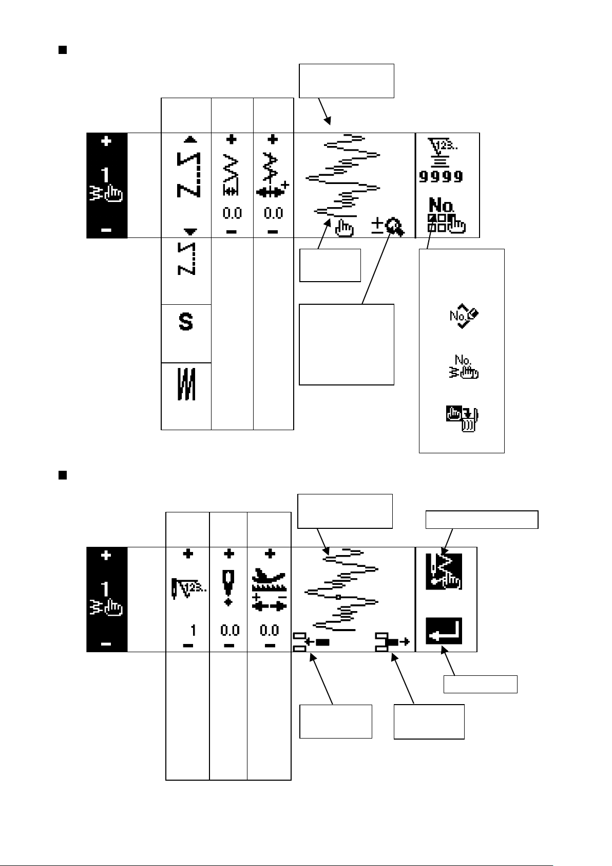
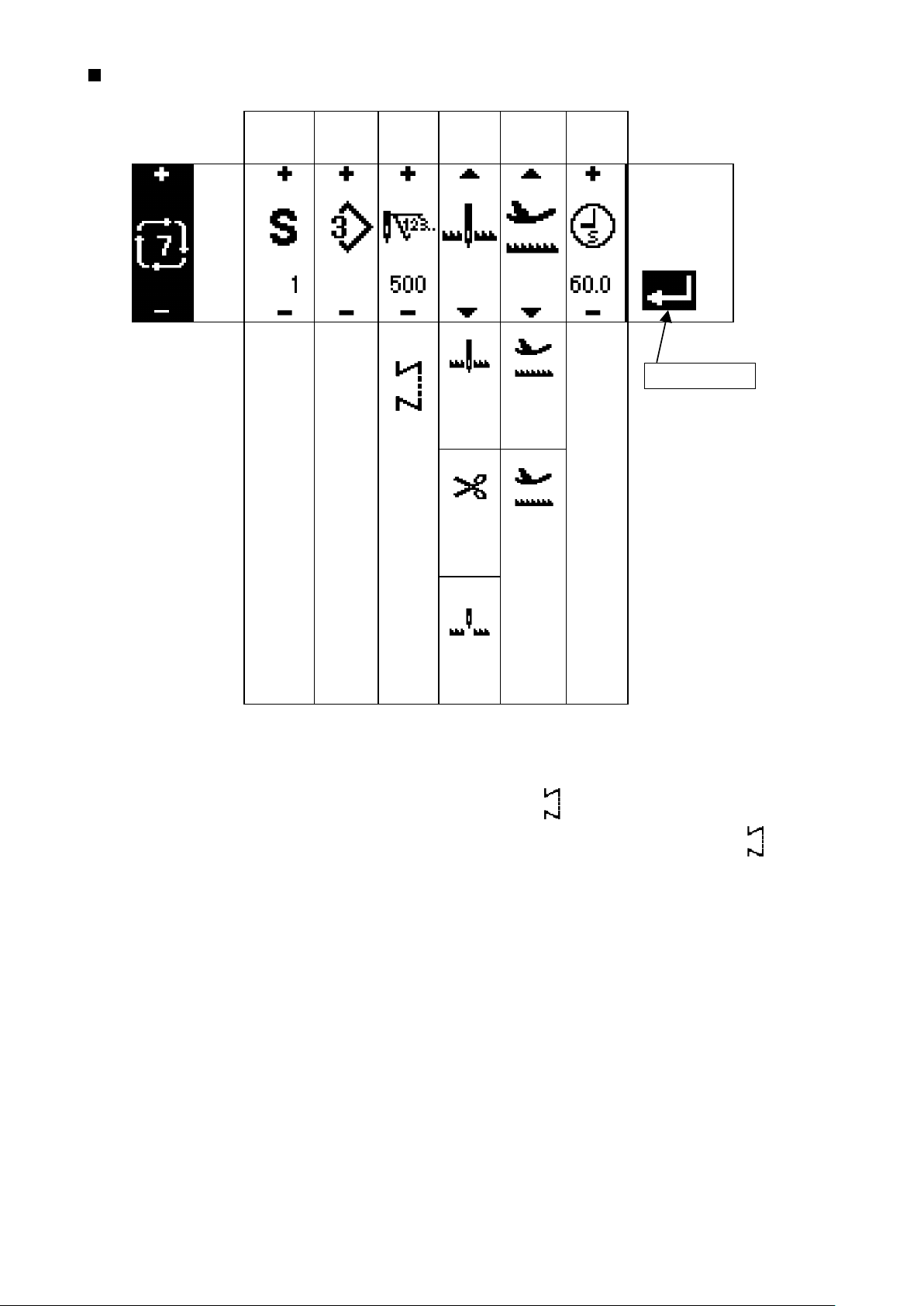
6-5. Setting the sewing pattern
WARNING :
Be sure to check presser foot and gauge currently being used before sewing after changing the zigzag pattern or zigzag width. In case where sewing is performed with the presser foot or gauge not
matching the zigzag width, it is in danger of accident such as needle breakage or the like.
(1) Selecting the zigzag pattern
When is pressed, the second screen is displayed.
:
1
When is pressed, the rst screen is displayed.
:
2
Straight stitch
2-step zigzag
Determined pattern
3-step zigzag
First screen
A
Continuous stitching
Second screen
Stitch, left
4-step zigzag
pattern sewing
Custom pattern
Blind stitch
Scallop
1
4
3
Pattern 1Stitch, right
Pattern 4Pattern 3Cycle stitching Pattern 2
2
(fagoting)
1) Select the zigzag pattern you desire to sew with the selection switch when the gure above is in the
screen. The determined pattern is displayed in section A.
2) For scallop and blind stitch, select the shape with the next screen.
Page 56

Left standard scallop
Determined pattern
Left crescent scallop
Left equal-width scallop of 24 stitches
Left equal-width scallop of 12 stitches
Right equal-width scallop of 12
Right equal-width scallop of 24
Right crescent scallop
Right standard scallop
5
In case of the scallop
1) Press scallop 3 and the
screen on the left side ap-
pears.
Press the pattern switch you
desire to select.
2) As an example, press left
crescent scallop 5 and
the screen on the left side
appears to determine the
pattern.
Determined pattern
Right blind stitch
Left blind stitch
In case of the blind stitch
1) Press blind stitch 4 and
the screen on the left side
appears.
Press the pattern switch you
desire to select.
6
2) As an example, press left
blind stitch 6 and the
screen on the left side
appears to determine the
pattern.
– 53 –
Page 57
– 54 –
6-6. Setting of the sewing shape
Zigzag width can be set from “0” to 10 mm. (Set value is limited by the max.zigzag width limitation.)
•
Stitch base line can be set as follows. When the center of zigzag is “0.0”, Right side : “+” Left side : “–”.
•
(1) 2-step zigzag, 3-step zigzag and 4-step zigzag stitch
Sewing shape list rst screen
2-step zigzag
1) Select 2-step (3-step or 4-step) zigzag stitch in the sewing shape list rst screen.
2) The selected shape reverses and is displayed on the left end of the screen.
3) Press to display the sewing shape setting screen.
Sewing shape setting screen
First screen
●
3-step zigzag
1122334
4-step zigzag
Second screen
●
667
7
4
5
8
Page 58

Setting of the zigzag width
¡
Change the zigzag width with +/– of switch 1.
Setting of the position of stitch base line
¡
Change the position of stitch base line with +/– of switch 2.
Setting of the reverse feed amount
¡
Change the reverse feed amount with +/– of switch 3.
Setting of the normal feed amount
¡
Change the normal feed amount with +/– of switch 4.
Display of the second screen
¡
Display the sewing shape setting second screen with switch 5.
Setting of the position of sewing start
¡
Set the position of sewing start with
▲/▼
of switch 6.
Sewing start Optional Sewing start Right Sewing start, left
Setting of the stop position
¡
Set the stop position with
Stop position, optional Stop position, right Stop position, left
Display of the rst screen
¡
Display the sewing shape setting rst screen with switch 8.
▲/▼
of switch 7.
– 55 –
Page 59
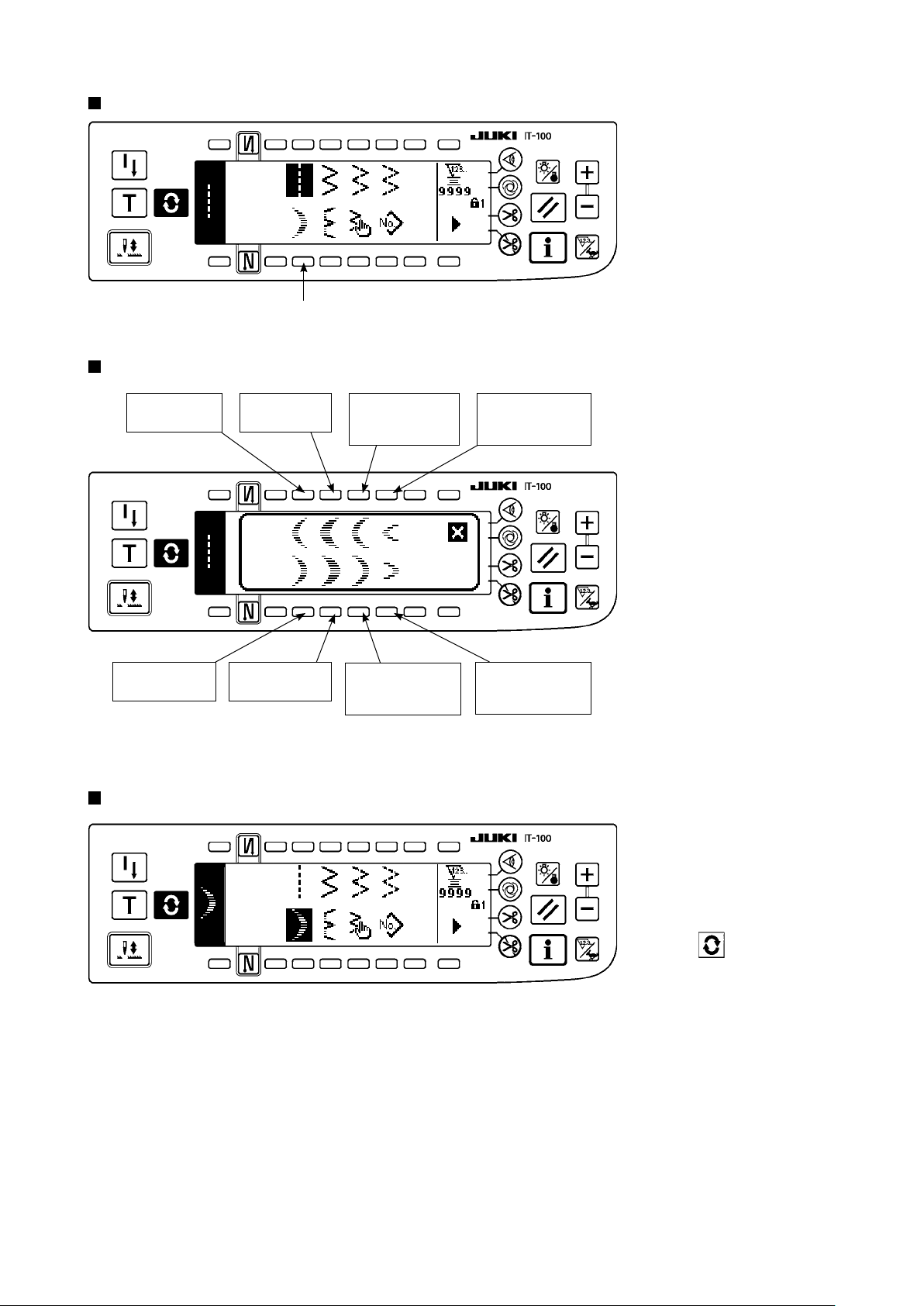
– 56 –
(2) Scallop stitching
Sewing shape list rst screen
1
Scallop selection pop-up screen
1) Select scallop stitching 1
in the sewing shape list
rst screen.
h
Left standard
scallop
Right standard
scallop
Sewing shape list rst screen
Left crescent
scallop
Right crescent
scallop
Left equal-width
scallop of 24
stitches
Right equal-width
scallop of 24
stitches
h
Left equal-width
scallop of 12
stitches
2) Press the switch of pattern
to be selected from the
screen of the left gure.
Right equal-width
scallop of 12
stitches
3) The selected shape
reverses and is indicated
on the left end of the
screen.
4) Press to display the
sewing shape setting
screen.
Page 60

Sewing shape setting screen
First screen
●
q w e r
q w e r t
Second screen
●
6 7 8
6 7 8 9
Setting of the zigzag width
¡
Change the zigzag width with +/– of switch 1.
Setting of the position of stitch base line
¡
Change the position of stitch base line with +/– of switch 2.
Setting of the reverse feed amount
¡
Change the reverse feed amount with +/– of switch 3.
Setting of the normal feed amount
¡
Change the normal feed amount with +/– of switch 4.
Display of the second screen
¡
Display the sewing shape setting second screen with switch 5.
Setting of the position of sewing start
¡
Set the position of sewing start with
▲ / ▼
of switch 6.
Sewing start, root Sewing start, crest
– 57 –
Page 61

– 58 –
Start from crest and start from root of scallop
●
Start of sewing
Start from
root
Setting of the stop position right/left
¡
Set the stop position with
Needle position
after thread
trimming
of switch 7.
▲ / ▼
Start from
crest
Normally, scallop starts the
sewing with the pattern of
start from root. However,
start from crest can be
selected by changing the
setting.
Stop position, optional Stop position, right Stop position, left
Setting of the stop position
¡
Set the stop position with
▲ / ▼
of switch 8.
Stop position, optional Stop position, root
Display of the rst screen
¡
Display the sewing shape setting rst screen with switch 9.
For the mirror sewing, refer to P.128.
Page 62

(3) Blind stitch sewing
Sewing shape list rst screen
1
h
Blind stitch selection pop-up screen
1) Select the blind stitch
sewing in the sewing
shape list rst screen.
2) Press the switch of pattern
to be selected from the
screen of the left gure.
Left blind stitch
Sewing shape list rst screen
Sewing shape setting screen
First screen
●
Second screen
●
q w e
5
5
w eq
Right blind stitch
h
4
4
3) The selected shape
reverses and is indicated
on the left end of the
screen.
4) Press to display the
sewing shape setting
screen.
Setting of the zigzag width
¡
Change the zigzag width
with +/– of switch 1.
Setting of the position of
¡
stitch base line
Change the position of
stitch base line with +/– of
switch 2.
Setting of the reverse
¡
feed amount
Change the reverse feed
amount with +/– of switch 3.
Setting of the normal
¡
feed amount
Change of the normal feed
amount with +/– of switch 4.
Change of the number of
¡
stitches
Change the number of
stitches with +/– of switch 5.
– 59 –
Page 63

– 60 –
(4) Custom pattern stitching
Sewing shape list rst screen
1
h
Custom pattern selection pop-up screen
1) Select custom pattern 1
in the sewing shape list
rst screen.
2) Press the custom pattern
No. to be selected.
Sewing shape list rst screen
Sewing shape setting screen
q w
h
wq
3) The selected shape
reverses and is indicated
on the left end of the
screen.
4) Press to display the
sewing shape setting
screen.
Setting of the zigzag
¡
width
Change the zigzag width
with +/– of switch 1.
Setting of the position of
¡
stitch base line
Change the position of
stitch base line with +/– of
switch 2.
Page 64

(5) T stitch, left
Sewing shape list second screen
1
1) Select T stitch, left sewing 1 in the sewing shape list second screen.
2) The selected shape reverses and is indicated on the left end of the screen.
3) Press to display the sewing shape setting screen.
Sewing shape setting screen
First screen
●
Second screen
●
1 2 3 4
1 2 3 4 5
6 7
6 7 8
The feed amount cannot be set to 0 and the T
stitch pattern may be deformed due to materials,
height of fed dog or gauges. (2nd stitch does not
correspond with 4th stitch.)
In this case, perform compensation with switch
“Setting of the compensation amount of seam
3
section at feed amount “0”” to make the stitches
correspond with each other.
Setting of the zigzag width
¡
Change the zigzag width with +/– of switch 1.
Setting of the position of stitch base line
¡
Change the position of stitch base line with +/– of switch 2.
– 61 –
1
3
2
4
Correspondence
Clearance
3
1
–
2
4
+
Page 65
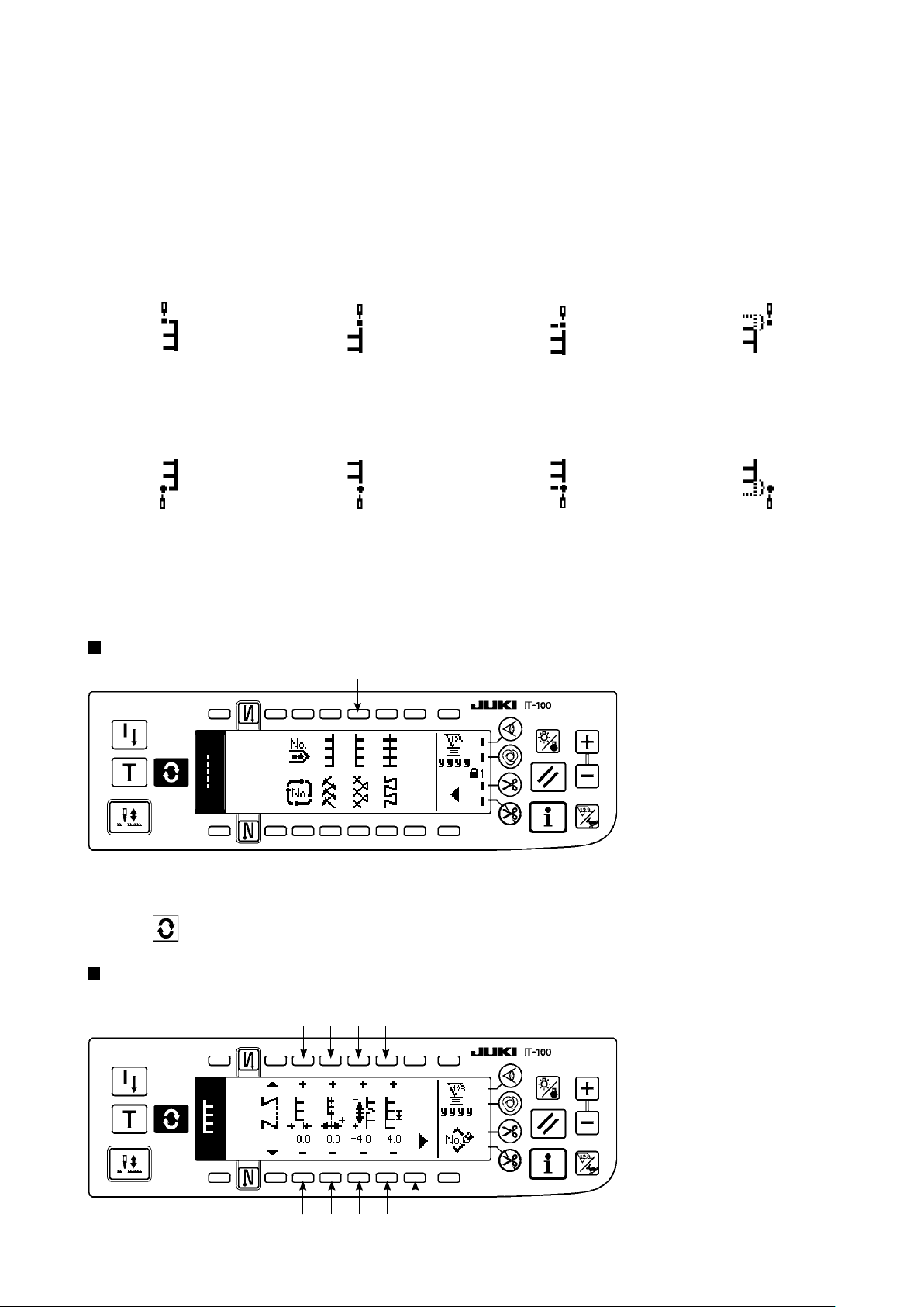
– 62 –
Setting of the compensation amount of seam section at feed amount "0"
¡
Change the normal feed amount with +/– of switch 3.
Setting of the normal feed amount
¡
Change the feed amount with +/– of switch 4.
Display of the second screen
¡
Display the sewing shape setting second screen with switch 5.
Setting of the position of sewing start
¡
Set the position of sewing start with ▲/▼ of switch 6.
Position of sewing start, left Position of sewing start, right 1 Position of sewing start, right 2 Free position of sewing start
Setting of the stop position
¡
Set the stop position with ▲/▼ of switch 7.
Position of sewing end, left Position of sewing end, right 1 Position of sewing end, right 2 Free position of sewing end
Display of the rst screen
¡
Display the sewing shape setting rst screen with switch 8.
(6) T stitch, right
Sewing shape list second screen
1
1) Select T stitch, right sewing 1 in the sewing shape list second screen.
2) The selected shape reverses and is indicated on the left end of the screen.
3) Press to display the sewing shape setting screen.
Sewing shape setting screen
First screen
●
1 2 3 4
1 2 3 4 5
Page 66
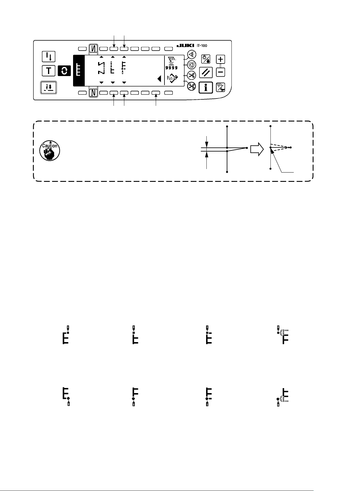
Second screen
●
6 7
6 7 8
The feed amount cannot be set to 0 and the
1
T sti t ch patt e rn may be de f or me d d ue to
materials, height of fed dog or gauges. (2nd
stitch does not correspond with 4th stitch.)
In this case, perform compensation with switch
“Setting of the compensation amount of
3
2
4
seam section at feed amount “0”” to make the
stitches correspond with each other.
Setting of the zigzag width
¡
Change the zigzag width with +/– of switch 1.
Setting of the position of stitch base line
¡
Change the position of stitch base line with +/– of switch 2.
Setting of the compensation amount of seam section at feed amount "0"
¡
Clearance
Change the feed amount with +/– of switch 3.
Setting of the normal feed amount
¡
Change the feed amount with +/– of switch 4.
Display of the second screen
¡
Display the sewing shape setting second screen with switch 5.
1
-
3
2
4
3
+
Correspondence
Setting of the position of sewing start
¡
Set the position of sewing start with ▲/▼ of switch 6.
Position of sewing start, left Position of sewing start, left 1 Position of sewing start, left 2 Free position of sewing start
Setting of the stop position
¡
Set the stop position with ▲/▼ of switch 7.
Position of sewing end, left Position of sewing end, left 1 Position of sewing end, left 2 Free position of sewing end
Display of the rst screen
¡
Display the sewing shape setting rst screen with switch 8.
– 63 –
Page 67

– 64 –
(7) Pattern 1
Sewing shape list second screen
1
1) Select pattern 1 sewing 1 in the sewing shape list second screen.
2) The selected shape reverses and is indicated on the left end of the screen.
3) Press to display the sewing shape setting screen.
Sewing shape setting screen
First screen
●
1 2 3 4
1 2 3 4 5
Second screen
●
Setting of the zigzag width
¡
Change the zigzag width with +/– of switch 1.
Setting of the position of stitch base line
¡
Change the position of stitch base line with +/– of switch 2.
Setting of the normal feed amount
¡
Change the feed amount with +/– of switch 3.
6 7
6 7 8
Setting of the compensation amount of seam section at feed amount "0"
¡
Change the normal feed amount with +/– of switch 4.
Page 68
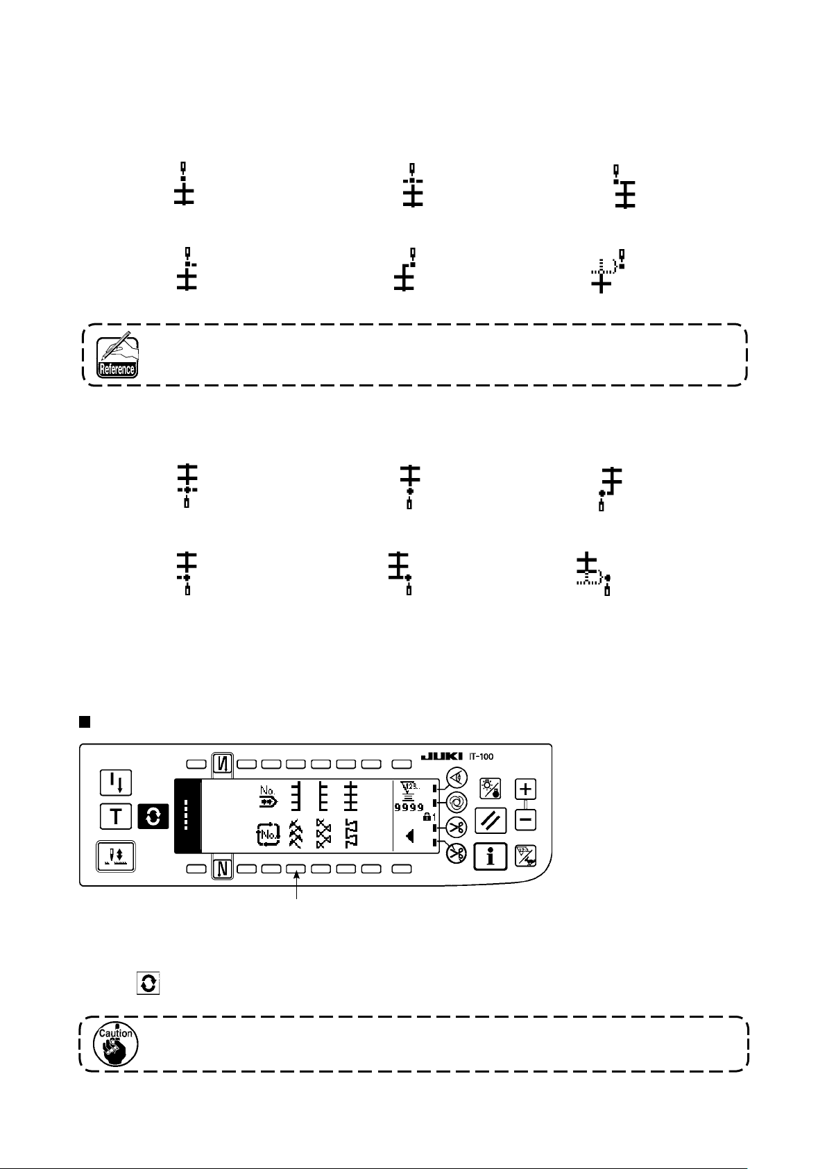
Display of the second screen
¡
Display the sewing shape setting second screen with switch 5.
Setting of the position of sewing start
¡
Set the position of sewing start with ▲/▼ of switch 6.
Position of sewing start, center 1 Position of sewing start, center 2 Position of sewing start, left
Position of sewing start, center 3 Position of sewing start, right Free position of sewing start
Free position of sewing start starts from the next needle entry after thread trimming.
Setting of the stop position
¡
Set the stop position with ▲/▼ of switch 7.
Position of sewing end, center 1 Position of sewing end, center 2 Position of sewing end, left
Position of sewing end, center 3 Position of sewing end, right Free position of sewing end
Display of the rst screen
¡
Display the sewing shape setting rst screen with switch 8.
(8) Pattern 2 (fagoting)
Sewing shape list second screen
1
1) Select pattern 2 sewing 1 in the sewing shape list second screen.
2) The selected shape reverses and is indicated on the left end of the screen.
3) Press to display the sewing shape setting screen.
When performing fagoting sewing, exclusive gauge is necessary. For the details, see
p.127.
– 65 –
Page 69

– 66 –
Sewing shape setting screen
First screen
●
1 2 3 4
1 2 3 4 5
Second screen
●
6 7
6 7 8
Setting of the zigzag width
¡
Change the zigzag width with +/– of switch 1.
Setting of the position of stitch base line
¡
Change the position of stitch base line with +/– of switch 2.
Setting of the reverse feed amount
¡
Change the reverse feed amount with +/– of switch 3.
Feed amount becomes “0” when the hand switch is pressed.
Setting of the normal feed amount
¡
Change the feed amount with +/– of switch 4.
Display of the second screen
¡
Display the sewing shape setting second screen with switch 5.
Setting of the position of sewing start
¡
Set the position of sewing start with ▲/▼ of switch 6.
Position of sewing start, right 1 Position of sewing start, center 1 Position of sewing start, left 1 Position of sewing start, left 2
Position of sewing start, center 2 Position of sewing start, right 2 Free position of sewing start
Free position of sewing start starts from the next needle entry after thread trimming.
Page 70

Setting of the stop position
¡
Set the stop position with ▲/▼ of switch 7.
Position of sewing end, right 1 Position of sewing end, center 1 Position of sewing end, left 1 Position of sewing end, left 2
Position of sewing end, center 2 Position of sewing end, right 2 Free position of sewing end
Display of the rst screen
¡
Display the sewing shape setting rst screen with switch 8.
(9) Pattern 3
Sewing shape list second screen
■
1
1) Select pattern 2 sewing 1 in the sewing shape list second screen.
2) The selected shape reverses and is indicated on the left end of the screen.
3) Press to display the sewing shape setting screen.
Sewing shape setting screen
■
First screen
●
1 2 3 4
1 2 3 4 5
– 67 –
Page 71

– 68 –
Second screen
●
6 7
6 7 8
Setting of the zigzag width
¡
Change the zigzag width with +/– of switch 1.
Setting of the position of stitch base line
¡
Change the position of stitch base line with +/– of switch 2.
Setting of the reverse feed amount
¡
Change the reverse feed amount with +/– of switch 3.
Feed amount becomes “0” when the hand switch is pressed.
Setting of the normal feed amount
¡
Change the feed amount with +/– of switch 4.
Display of the second screen
¡
Display the sewing shape setting second screen with switch 5.
Setting of the position of sewing start
¡
Set the position of sewing start with ▲/▼ of switch 6.
Position of sewing start, right 1 Position of sewing start, center 1 Position of sewing start, left 1 Position of sewing start, left 2
Position of sewing start, center 2 Position of sewing start, right 2 Free position of sewing start
Free position of sewing start starts from the next needle entry after thread trimming.
Setting of the stop position
¡
Set the stop position with ▲/▼ of switch 7.
Position of sewing end, right 1 Position of sewing end, center 1 Position of sewing end, left 1 Position of sewing end, left 2
Position of sewing end,
Display of the rst screen
¡
Display the sewing shape setting rst screen with switch 8.
center
2 Position of sewing end, right 2 Free position of sewing end
Page 72

(10) Pattern 4
Sewing shape list second screen
1
1) Select pattern 2 sewing 1 in the sewing shape list second screen.
2) The selected shape reverses and is indicated on the left end of the screen.
3) Press to display the sewing shape setting screen.
Sewing shape setting screen
First screen
●
1 2 3 4
1 2 3 4 5
Second screen
●
Setting of the zigzag width
¡
Change the zigzag width with +/– of switch 1.
Setting of the position of stitch base line
¡
Change the position of stitch base line with +/– of switch 2.
Setting of the reverse feed amount
¡
Change the reverse feed amount with +/– of switch 3.
6 7
6 7 8
Feed amount becomes “0” when the hand switch is pressed.
– 69 –
Page 73

– 70 –
Setting of the normal feed amount
¡
Change the feed amount with +/– of switch 4.
Display of the second screen
¡
Display the sewing shape setting second screen with switch 5.
Setting of the position of sewing start
¡
Set the position of sewing start with ▲/▼ of switch 6.
Position of sewing start, left 1 Position of sewing start, left 2 Position of sewing start, right 1 Position of sewing start, right 2
Position of sewing start, right 3 Position of sewing start, left 3 Free position of sewing start
Free position of sewing start starts from the next needle entry after thread trimming.
Setting of the stop position
¡
Set the stop position with ▲/▼ of switch 7.
Position of sewing end, left 1 Position of sewing end, left 2 Position of sewing end, right 1 Position of sewing end, right 2
Position of sewing end, right 3 Position of sewing end, left 3 Free position of sewing end
Display of the rst screen
¡
Display the sewing shape setting rst screen with switch 8.
Page 74

6-7. Setting of the sewing speed
The sewing speed can be set at each pattern (cycle stitching is not possible to set the number of rotations).
Setting of the sewing speed can be performed in the reverse feed stitching setting second screen (when the
pattern is the overlapped stitching, perform it in the overlapped stitching setting second screen).
Reverse feed stitching setting second screen
1
1
: Sewing speed is set. 200 to 5,000 can be set in increments of 100.
1
Sewing speed is limited by zigzag width, feed amount, function setting No. 96 Max. sewing speed
setting, etc.
In this case, the minimum setting is prior.
There are cases where the shapes are not stabilized in case of some custom patterns which frequently
repeat normal and reverse feed stitching.
In this case, set the sewing speed at approximately 2,000 sti/min.
6-8. Reverse feed stitching
OFF ON ON
1
A
B
Sewing
pattern
OFF OFF
2
Reverse feed stitching setting screen
q
OFF
A
C
D
ON ON
Reverse feed stitching can be set with each zigzag pat-
tern.
Effective/ineffective of reverse feed stitching can be set
by pressing reverse feed stitch at sewing start switch 1
B
and reverse feed stitch at sewing end switch 2. In case
the reverse feed stitching is effective, the respective
shapes of the reverse feed stitching are displayed. In
case of ineffective, the shape is not displayed.
C
D
w
For the reverse feed stitching, there are standard condensation, 2-point condensation and condensation custom.
– 71 –
Page 75

– 72 –
(1) Standard condensation
Standard condensation performs reverse feed stitching at the same needle entry as that of the selected zig-
zag pattern.
Example) Reverse feed stitching at sewing end
Zigzag pattern section
3-step zigzag stitching
Standard condensation section
Process C : 4-times setting
Example) In case of free stitching of the standard zigzag stitch
1) Press to display reverse feed stitching setting screen.
2) Set the shape of condensation and number of stitches.
: Select the shape of condensation at the sewing start.
1
: Set the number of stitches of process A with “+” and “–”.
2
: Set the number of stitches of process B with “+” and “–”.
3
: Select the shape of condensation at the sewing end.
4
: Set the number of stitches of process C with “+” and “–”.
5
: Set the number of stitches of process D with “+” and “–”.
6
: Reverse feed stitching setting second screen is displayed.
7
Display section of 1 and 4 : Standard condensation, 2-point condensation and condensation custom
(20 patterns) are changed over and displayed.
Reverse feed stitching setting (standard condensation) screen
qqwweerrtty
y
7
Page 76
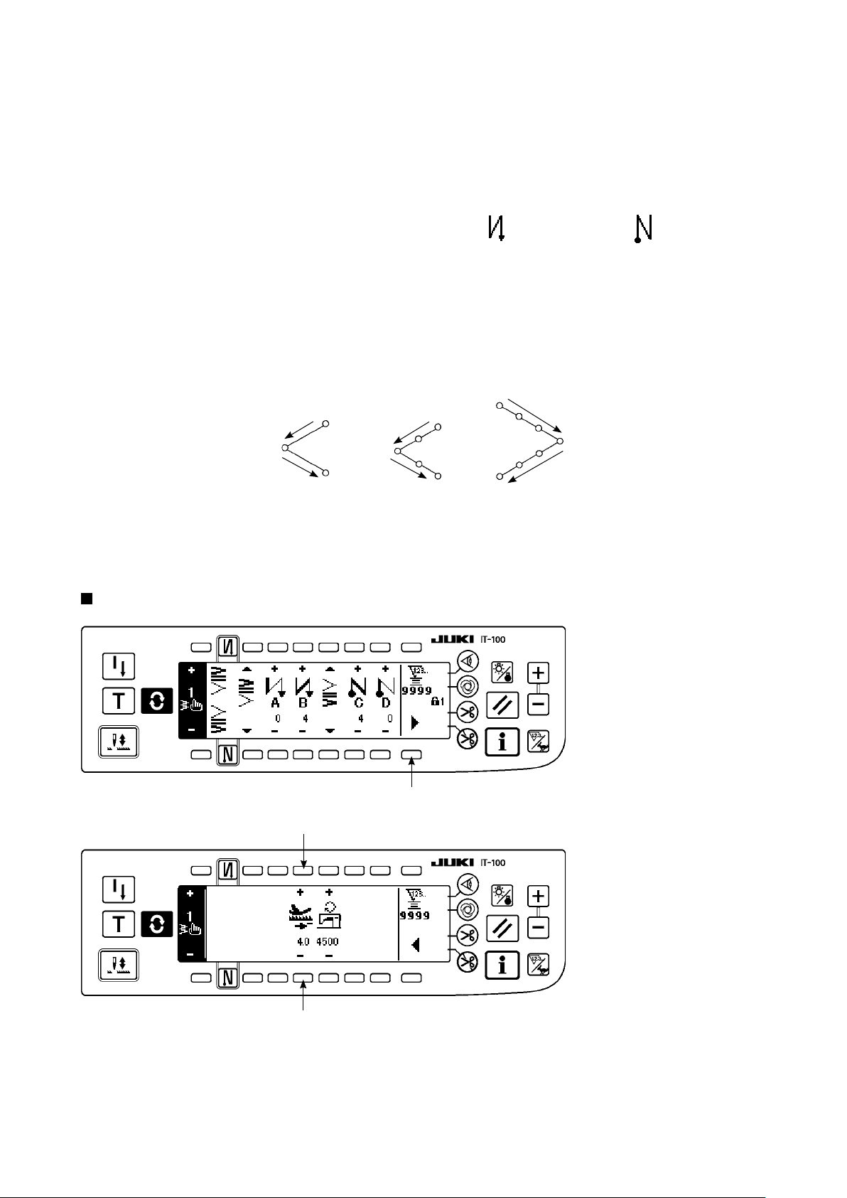
* For the reverse feed stitching setting, there are two kinds of methods below according to the zigzag patterns.
1) In case of straight stitch, scallop stitch, blind stitch, custom and continuous stitch, set the reverse feed
stitching with the number of stitches.
Reverse feed stitching at sewing start → A (feed in normal direction) : 0 to 19 stitches can be set.
B (feed in reverse direction) : 0 to 19 stitches can be set.
Reverse feed stitching at sewing end → C (feed in reverse direction): 0 to 19 stitches can be set.
D (feed in normal direction) : 0 to 19 stitches can be set.
……
……
……
……
2
3
5
6
* The pictures in case of straight stitching are 1 sewing start and 4 sewing end .
2) In case of 2-step zigzag, 3-step zigzag and 4-step zigzag, set the reverse feed stitching with the number
of times of zigzag pattern. Zigzag pattern means the space between the returning points of zigzag.
Reverse feed stitching at sewing start → A (feed in normal direction) : 0 to 19 times can be set.
B (feed in reverse direction) : 0 to 19 times can be set.
Reverse feed stitching at sewing end → C (feed in reverse direction): 0 to 19 times can be set.
D (feed in normal direction) : 0 to 19 times can be set.
………
………
………
………
2
3
5
6
1 time
2 time
2-step zigzag
stitch
1 time
2 time
3-step zigzag
stitch
4-step zigzag
1 time
2 time
stitch
* Setting of the reverse feed amount of custom pattern stitching or continuous stitching
: Transits to the second screen.
7
Reverse feed stitching setting second screen
7
9
9
: Feed amount at the time of automatic reverse feed stitching or pressing the hand switch is set. The
9
feed amounts from the feed amount set in the pattern setting screen to the reverse feed amount set
here continuously change by pressing down the reverse feed control lever during sewing.
– 73 –
Page 77

– 74 –
(2) 2-point condensation
2-point condensation performs reverse feed stitching of two points between the existing needle entry of the
selected zigzag pattern and the next needle entry.
The width between two points can be adjusted in the direction of “–”.
Example) Reverse feed stitching at sewing end
Zigzag pattern section
3-step zigzag stitch
2-point condensation section
Process C : 4 stitches setting
Compensation can be performed in the direction of “–”. (In case of the
gure, the width narrows to the left side.)
Example) In case of free stitching of the 2-step zigzag stitch
1) Press to display reverse feed stitching setting screen.
2) Set the shape of condensation and number of stitches with the rst screen.
: Select the shape of condensation at the sewing start.
1
: Set the number of stitches of process A with “+” and “–”. 0 to 19 stitches can be set.
2
: Set the number of stitches of process B with “+” and “–”. 0 to 19 stitches can be set.
3
: Select the shape of condensation at the sewing end.
4
: Set the number of stitches of process C with “+” and “–”. 0 to 19 stitches can be set.
5
: Set the number of stitches of process D with “+” and “–”. 0 to 19 stitches can be set.
6
Display section of 1 and 4 : Standard condensation, 2-point condensation and condensation custom
(20 patterns) are changed over and displayed.
3)
Set 2-point condensation width adjustment with the second screen. (Width can be narrowed up to max. –
mm.)
: Set 2-point condensation width adjustment at the sewing start.
7
: Set 2-point condensation width adjustment at the sewing end.
8
* 2-point condensation width adjustment can narrow the width from the rst needle entry position to the next
needle entry position when performing the reverse feed stitching. (When set value is “0”, there is no compensation.)
* When the width adjustment is performed, the width between 2 points can be narrowed and the fray of
thread is lessened.
The rst screen of reverse feed stitching setting (2-point condensation)
■
5
q w e r t y
q w e r t y
Press to display the second screen.
Page 78

The second screen of reverse feed stitching setting (2-point condensation)
u i
u i
Press to display the rst screen.
(3) Condensation custom
Condensation custom performs reverse feed stitching with the optional needle entry which has been input-
ted.
1) Select the shape of condensation with the rst screen.
: Select the shape of condensation at the sewing start.
1
: Select the shape of condensation at the sewing end.
3
2) Set the width of condensation custom pattern with the second screen.
: Needle entry position is displayed.
2, 4
: Total display and partial display of the condensation custom pattern are changed over.
5
: Set the width of condensation custom pattern at the sewing start.
6
: Set the width of condensation custom pattern at the sewing end.
7
* Separately set inputted zigzag width of condensation custom from that of normal sewing section. Set the
width within the range of maximum zigzag width limitation.
* By setting the width, the needle entry differs from actually inputted needle entry position.
The rst screen of reverse feed stitching setting (condensation custom)
q w e r
q w e r
Press to move the screen to the edit screen.
* For the editing procedure, refer to the item of 6-10.Custom pattern.
Press to display the second screen.
– 75 –
Page 79

The second screen of reverse feed stitching setting (condensation custom)
6 7
6 7
Press to display the rst screen.
(4) Comparision table of the reverse stitch of each shape
Standard condensation 2-point condensation Condensation custom
Sewing start Sewing end Sewing start Sewing end Sewing start Sewing end
Straight stitch
2-step zigzag
stitch
3-step zigzag
stitch
4-step zigzag
stitch
Scallop
Blind stitch
T stitch, left
T stitch, right
Pattern 1
Pattern 2
(fagoting)
Pattern 3
Pattern 4
Custom
Continuous
stitch
– 76 –
Page 80

6-9. Selection of the kind of stitching
Standard delivery level of the key lock is “1”. When the level of the key lock is the case
other than “0”, be sure to change the level to “0” to perform the operation below.
Example) 2-step zigzag
Sewing shape setting screen
q
q
(1) Overlapped stitching
Select the kind of stitching
from among free stitching
, overlapped stitching and
programmed stitching .
Press switch 1 of sewing
shape setting screen to se-
lect the kind.
The rst screen of the
overlapped stitching setting screen
w e r t
w e r t
1) Select showing overlapped stitching with 1 of sewing shape setting screen.
2) Press in the sewing shape setting screen to display the rst screen of the overlapped stitching setting.
3) Input the number of stitches of the respective processes and the number of processes in the rst screen
of the overlapped stitching setting.
: Set the number of stitches of process A with “+” and “–”. 0 to 19 stitches for the number of stitches of
2
section A can be set.
: Set the number of stitches of process B with “+” and “–”. 0 to 19 stitches for the number of stitches of
3
section B can be set.
: Set the number of stitches of process C with “+” and “–”. 0 to 19 stitches for the number of stitches of
4
section C can be set.
: Set the number of processes with “+” and “–”. 0 to 9 times for the number of processes can be set.
5
: The second screen of the overlapped stitching setting is displayed.
6
4) Set the enlargement/reduction of the needle entry and the max. sewing speed in the second screen of the
overlapped stitching setting.
5) By performing depressing the front part of the pedal, the sewing machine repeats the specied number of
times of normal and reverse feed stitching, performs automatic thread trimming and stops.
* Turn ON the thread trimming prohibition switch ON when you desire to stop the sewing machine with
needle UP position without performing thread trimming after all processes have been completed.
* Thread trimming is performed at any occasion in case of one-shot stitching and the last of process. The
one-shot stitching cannot be turned OFF.
– 77 –
Page 81

– 78 –
The second screen of the
1 2
overlapped stitching setting screen
1 2
: Enlargement/reduction of the needle entry can be performed.
1
: Max. number of revolutions can be set.
2
: The rst screen of the overlapped stitching is displayed.
3
3
(2) Programmed stitching
Programmed stitching
Programmed stitching can program the constant-dimension stitching process up to 20 steps and set the
number of stitches to each step up to 500 stitches.
* For the programmed stitching, the pattern registration cannot be performed.
Example) 2-step zigzag
Sewing shape setting screen
q
1) Select showing
programmed stitching with
of sewing shape setting
1
screen.
q
Page 82

Programmed stitching selection screen
w
w
Press , in case of more than 10 steps, and programmed stitching
selection screen of “11” to “20” is displayed.
Press and the screen returns to programmed stitching selection screen
of “01” to “10”.
When automatic thread trimming is selected, “0” is not displayed in the last step.
When increasing the number of steps, proceed to the next step after releasing automatic thread
trimming.
2) Press to display the
programmed stitching
setting screen.
3) Number of stitches of
each step is displayed in
the programmed stitching
setting screen.
Press switch 2
corresponding to each
step and the screen
moves to the programmed
stitching edit screen.
Programmed stitching edit screen
e r
e r
4) Set the number of stitches of each step in the programmed stitching edit screen.
: Set the step with “+” and “–”. As many as 20 steps can be set.
3
: Set the number of stitches with “+” and “–”. As many as 500 stitches can be set.
4
5) When setting of all steps has been completed, select automatic thread trimming 6 at the last step, or set “0”
stitch to the next step.
When the last step is “20”, it is not necessary to set “0” stitch at the next step.
6) When setting is completed, press key to determine the contents of setting.
When the power source is turned OFF without pressing key, the inputted data returns
to the former one. When you desire to determine the data, be sure to press key.
t
y
One-shot automatic stitching
One-shot automatic stitching can be set by each step.
1) In the programmed stitching edit screen, press one-shot automatic stitching switch 5 to select the one-
shot automatic stitching. (When it is in the selected state, a mark is displayed on the side of switch 5.)
2) In the step where the one-shot automatic stitching has been selected, the sewing machine will automatically
continue sewing, once the sewing machine starts running, until the number of stitches of the step is reached.
– 79 –
Page 83

– 80 –
Teaching
Teaching can input the number of stitches of inputting step with the number of stitches which has been actually sewn.
1) Press switch in the programmed stitching edit screen and the teaching mode is selected.
2) Depress the front part of the pedal to sew until the last stitch of the step is reached.
* At this time, input of number of stitches cannot be performed by turning handwheel by hand or using
needle up/down compensating switch.
3) Stop the sewing machine with the pedal in the neutral position and the number of stitches which has been
sewn is displayed on 2.
: Set the step with "+".
1
: Number of stitches which has been sewn can be corrected by hand with “+” and “–”.
2
4) Make the step of 1 proceed to the subsequent step or make the sewing machine perform thread trim-
ming. Then the input of the number of stitches for the step is completed.
Teaching screen
■
q w
w
6-10. Custom pattern
Standard delivery level of the key lock is “1”. When the level of the key lock is the case other than
“0”, be sure to change the level to “0” to perform the operation below.
There are cases where the sewing shapes are not stabilized in case of the patterns which frequently repeat
・
normal and reverse feed stitching. Use the machine at the sewing speed of approximately 2,000 sti/min.
There are cases where the value inputted to the operation panel and the actual sewing pitch are different from each
・
other due to materials and gauges. Perform compensation of the pitch in accordance with the sewing products.
Free needle entry position can be specied and optional zigzag pattern can be created.
As many as 20 patterns can be created and as many as 500 stitches of each pattern can be inputted.
(1) Custom pattern setting
Sewing shape list screen
1) Press switch 1 of
in the sewing shape list
screen.
q
Page 84

Custom pattern selection pop-up screen
w
corre-
2
Sewing shape setting screen
2)
Press switch
sponding to the pattern
which has been registered
in the custom pattern se-
lection pop-up screen.
ye r t
3) Press to display the
sewing shape setting
screen.
e r t
4)
Zigzag width, position of stitch base line, etc. of custom pattern can be set in the sewing shape setting screen.
: Select free stitching, overlapped stitching or programmed stitching.
3
: Set the zigzag width with “+” and “–”.
4
(The whole can be enlarged or reduced taking the inputted left and right positions as reference.)
: Set the position of stitch base line with “+” and “–”.
5
: Needle entry position is displayed.
6
:
Total display and partial display of the custom pattern are changed over.
7
7
(2) New creation of the custom pattern
Custom pattern is newly created.
New creation pop-up screen
q
q
1) Press in the custom pattern selection pop-up screen to display the new creation pop-up screen.
2) Nos. which have not been registered at present are displayed in 1. Select the No. you desire to obtain
with “+” and “–”.
When is pressed here, the screen returns to the former one without creating the pattern.
3) When is pressed, new creation is performed.
The No. which has been created is in the selective state. Continue to perform the edit of custom pattern.
– 81 –
Page 85

– 82 –
(3) Custom pattern edit
1) Press switch of in the sewing shape setting screen to move to the custom pattern edit screen.
Custom pattern edit screen
63 4 5
3 4
2) Set the needle entry position and sewing direction of each step in the custom pattern edit screen.
: Set the step with
3
: Set the value of needle entry point from the center of zigzag with
4
right side and
: Set the feed amount with “+” or “–”.
5
: Needle entry position is displayed. (In display of the needle entry position, all positions are displayed
6
as the normal direction.)
: Insert needle entry point 0.0 for one stitch to the existing step. Then the stitches move backward one
7
stitch by one stitch.
* It is not possible to insert it when the number of total stitches is 500 stitches.
: Delete one stitch of the needle entry of the existing step. Then the stitches move forward one stitch
8
by one stitch.
* It is not possible to delete it when the number of total stitches is “1” stitch.
3)
When setting is completed up to the last step, proceed to the next step, press
“+” and “–”
value on the left side.
“–”
5
7
.
8
9
“+”
and
9
“–”. “+”
value comes on the
and put END mark .
* When the number of stitches of the last step is 500 stitches, it is not necessary to set “END” mark .
4) When the setting is completed, press key to determine.
When the power source is turned OFF without pressing key, the inputted data returns to
the former one. When you desire to determine the data, be sure to press key.
When the setting of the feed direction of the custom patternis set to the reverse direction,
the max. speed is limited in accordance with the feed amount used.
(4) Pattern sewing registration, custom pattern copy and custom pattern deletion of
the custom pattern
Pop-up screen of pattern registration, copy and deletion of custom pattern
q w e
Press in the sewing shape setting screen, and the pop-up screen of pattern registration, copy and deletion of
custom pattern appears. Then pattern registration, copy and deletion of the custom pattern can be performed.
Page 86

Registration of pattern
○
Registration pop-up screen
r
1) Press 1 in the
pop-up screen of pattern
registration, copy and de-
letion of custom pattern.
r
2) Select the pattern No. you desire to register with 4 in the registration pop-up screen.
When is pressed here, the screen returns to the former one without registering the pattern.
3) When is pressed, registration is performed.
After registration, the registered pattern is in the selective state.
○
How to copy
Copy pop-up screen
t y
1) Press 2 in the pop-
up screen of pattern
registration, copy and de-
letion of custom pattern.
t y
2) Copy pop-up screen is displayed.
: Select the custom pattern of copy source with “+” and “–”. (It is possible to select only No.
5
which has been registered.)
: Select the custom pattern of copy destination with “+” and “–”. (It is possible to select only No.
6
which has been not registered.)
When is pressed here, the screen returns to the former one without performing copy.
3) When is pressed, copying is performed.
When copying is performed, the No. which is selected as copy destination is in the selective state.
– 83 –
Page 87

– 84 –
○
How to delete
Deletion pop-up screen
u
u
1) Press 3 in the copy pop-up screen and the deletion pop-up screen to display the deletion pop-up
screen.
2) Select the pattern No. you desire to delete in the deletion pop-up screen.
: Select the pattern to be deleted with “+” and “–”.
7
When is pressed here, the screen returns to the former one without deleting.
3) When is pressed, deletion is performed.
Once the data is deleted, it does not return to the former one. Be sure to press after
carefully checking the data.
When the number of registered pieces is one, deletion cannot be performed. When you
desire to delete it, perform deletion after creating another No.
The custom pattern registered in the pattern cannot be deleted.
6-11. Condensation Custom
Standard delivery level of the key lock is “1”. When the level of the key lock is the case
other than “0”, be sure to change the level to “0” to perform the operation below.
Condensation custom can perform condensation by specifying free needle entry position.
Condensation custom patterns can be created up to as many as 64 steps. As many as 20 patterns can be
registered at the sewing start and the sewing end respectively.
(1) Condensation custom setting
Reverse feed stitching setting (condensation custom) screen
q
4
q
w
e
r
65
Page 88

1) Press to display the reverse feed stitching setting screen.
2) Select the shape of condensation in the reverse feed stitching screen.
: Select the shape of condensation at sewing start from among 1 to 20.
1
Standard condensation , 2-point-condensation and condensation customs to are
changed over and displayed in the display section.
: Select the shape of condensation at sewing end from among 1 to 20.
4
Standard condensation , 2-point condensation and condensation customs to are
changed over and displayed in the display section.
: Needle entry position is displayed when selecting the condensation custom.
,
2
5
: Total display and partial display of the condensation custom pattern are changed over.
,
3
6
(2) Condensation custom edit
Condensation custom edit screen
q w
q w
3) Set the needle entry position for each step in the condensation custom edit screen.
: Set the step with “+” and “–” key.
1
: Set the value of needle entry point from the center of zigzag with “+” and “–”. “+” value comes
2
r t
7
e
y
1) Press to display the
reverse feed stitching set-
ting screen.
2) Press
reverse feed stitching set-
ting screen to move to the
condensation custom edit
screen.
2
or 4
on the right side and “–” value on the left side.
: Needle entry position is displayed.
3
: Insert needle entry point 0. 0 for one stitch to the existing step. Then the stitches move back-
4
ward one stitch by one stitch.
* It is not possible to insert it when the number of total stitches is 64 stitches.
: Delete one stitch of the needle entry of the existing step. Then the stitches move forward one stitch
5
by one stitch.
* It is not possible to delete it when the number of total stitches is “1” stitch.
: Set the feed amount with “+” and “–”.
7
in the
4)
When setting up to the last step is completed, proceed to the next step, press ❻and put END mark
* When the last step is 64, it is not necessary to set “END” mar
5) When all settings have been completed, press
key to determine.
– 85 –
.
.
Page 89

– 86 –
Reverse feed stitching setting screen
q
q
The second screen of the reverse feed stitching setting is explained, taking the example of the input of con-
densation custom at sewing start (width 4mm for 2-step zigzag stitch).
Example) Condensation custom at sewing start Width 4 mm for 2-step zigzag stitch
2
Input the data of the list in the condensation custom edit screen.
1
Set 4 mm at 1 in the 2nd screen of reverse feed stitching setting.
2
Needle
entry
Input
value
Feed
amount
1th
stitch
-2.0 -0.7 0.6 2.0 0.6 -0.7 -2.0 -0.7 0.6 2.0 END
2th
stitch
0.1 0.1 0.1 0.1 0.1 0.1 0.1 0.1 0.1 0.1
3th
stitch
4th
stitch
5th
stitch
6th
stitch
7th
stitch
8th
stitch
9th
stitch
* By changing at 1, the inputted needle entry (width shown at 2) can be enlarged/reduced.
When the power source is turned OFF without pressing key, the inputted data returns
to the former one. When you desire to determine the data, be sure to press key.
The feeding directions of the condensation custom patterns are all in the reverse feed
directions.
10th
stitch
11th
stitch
Page 90
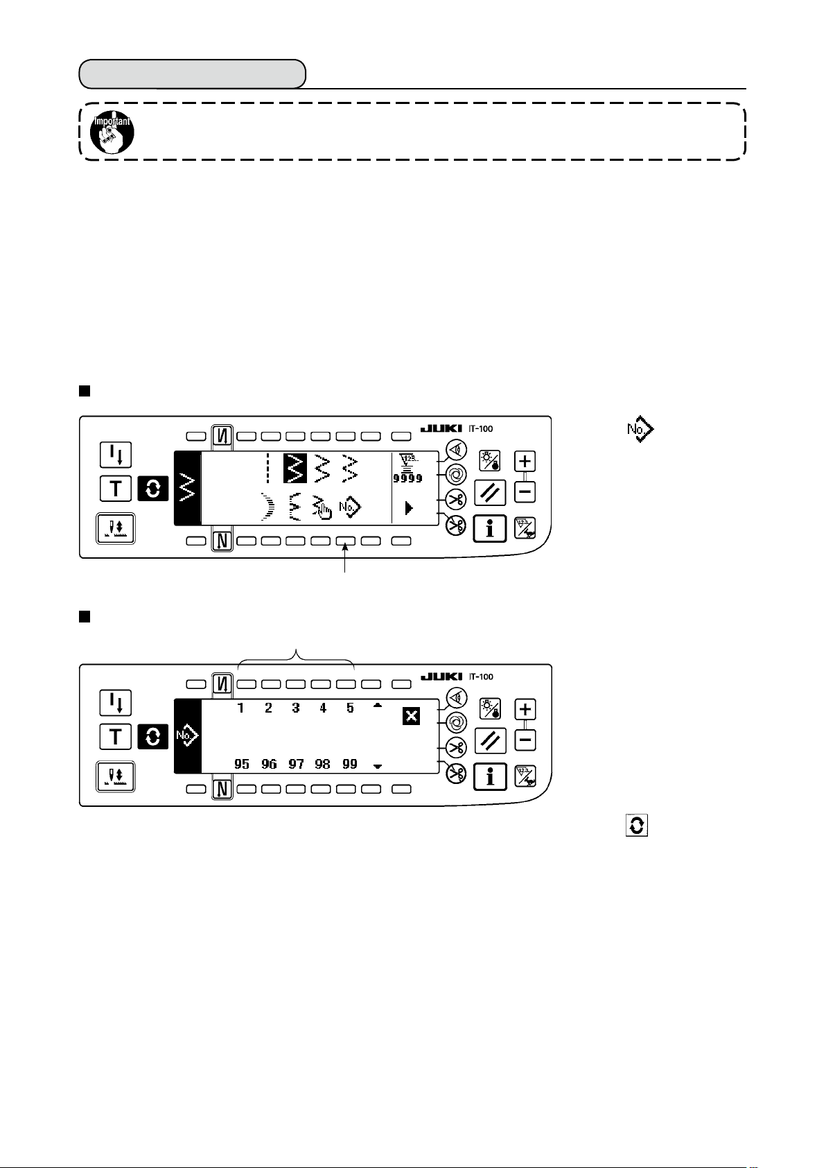
6-12. Pattern stitching
Standard delivery level of the key lock is “1”. When the level of the key lock is the case
other than “0”, be sure to change the level to “0” to perform the operation below.
The respective shapes of straight stitch, 2-step zigzag, 3-step zigzag, 4-step zigzag, scallop, blind stitch, T
stitch, patterns 1 to 4 and custom can be registered in the pattern.
Patterns, the zigzag width of which is different from each other, and those, the positions of the stitch base
line of which are different from each other can be changed over and used without re-setting the data even in
case of the same zigzag shape by registering as patterns. Continuous stitching or cycle stitching can be set
by using the registered pattern.
It is possible to register as many as 99 patterns.
(1) Setting the pattern stitching
Example) Scallop stitching
The second screen of the sewing shape list
1) Select 1 in the sec-
ond screen of the sewing
shape list.
Pattern selection pop-up screen
w
q
2) Press switch 2 corre-
sponding to the sewing
which has been reg-
istered, or the pattern
you desire to edit in the
pattern selection pop-up
screen.
3) Press to display the
sewing shape setting
screen.
– 87 –
Page 91

– 88 –
Sewing shape setting screen
q
e
* When there is the second
screen, 4 is displayed.
q
w e
r
t
4) Setting of the respective items can be performed in the sewing shape setting screen.
Shape
Straight
2-step zigzag
3-step zigzag
4-step zigzag
Scallop
Blind stitch
T stitch, left
T stitch, right
Pattern 1
Pattern 2
Pattern 3
Pattern 4
Custom
: Pattern No. which has been registered can be selected with “+” and “–”.
1
: Select the pattern shape. Sewing shape can be changed by the pattern No. which is being selected
2
Zigzag
width
-
○
○
○
○
○
○
○
○
○
○
○
○
Position of
stitch base
line
○
○
○
○
○
○
○
○
○
○
○
○
○
Reverse
feed
amount
○
○
○
○
○
○
-
-
-
-
-
-
-
Normal
feed
amount
○
○
○
○
○
○
○
○
○
○
○
○
-
Compensation
value
-
-
-
-
-
-
○
○
○
○
○
○
-
Position at
sewing
start
-
○
○
○
○
-
○
○
○
○
○
○
-
Stop
position
-
○
○
○
○
-
○
○
○
○
○
○
-
at present.
Number of
stitches of
blind stitch
-
-
-
-
-
○
-
-
-
-
-
-
-
When the sewing shape is changed, the respective setting data return to the initial values.
: Select the kind of stitching. Free stitching and overlapped stitching can be selected.
3
Page 92

(2) Registering the pattern stitching
It is possible to register at the time of free stitching and overlapped stitching.
Select in advance the shape you desire to register from the sewing shape list screen.
Example) Scallop stitching
Sewing shape setting screen
1) Press to display the
sewing shape setting
screen.
2) Press 1 to display
the new registration pop-
up screen in the sewing
shape setting screen.
q
New registration pop-up screen
w
3) Select the pattern No.
to which you desire to
register with 2 in the new
registration pop-up screen.
When is pressed here,
the screen returns to the
former one without per-
w
4) When is pressed, registration is performed.
The registered pattern is in the selective state after registration has been performed.
forming the registration.
(3) Copy and deletion of the pattern stitching
Press 5 in the sewing shape setting screen to display the copy and deletion pop-up screen. Then copy
and deletion of the pattern stitching can be performed.
How to copy
○
Copy and deletion pop-up screen
1) Press 1 in the
copy and deletion pop-
up screen to display the
copy pop-up screen.
q w
– 89 –
Page 93

– 90 –
Copy pop-up screen
e r
2) Se t the pattern Nos. of
the copy source and copy
desti n a t i o n in the copy
pop-up screen.
e r
: Select pattern No. of the copy source with
3
: Select pattern No. of the copy destination with
4
ed.)
When is pressed here, the screen returns to the former one without performing copy.
3) When is pressed, copy is performed.
No. of the copy destination is in the selective state after copy has been performed.
How to delete
○
Deletion pop-up screen
“+” and “–”
. (Registered Nos. only can be selected.)
“+” and “–”
. (Non-registered Nos. only can be select-
t
1) Press 2 in the
copy and deletion pop-
up screen to display the
deletion pop-up screen.
2) Select pattern No. you
desire to delete in the
deletion pop-up screen.
: Select the pattern to
t
5
be deleted with “+” and
“–”.
When is pressed here, the screen returns to the former one.
3) When is pressed, deletion is performed.
Once the deletion is performed, the data is not restored.
Be sure to carefully check before pressing
When the number of registered pieces is one, deletion cannot be performed. When you
desire to delete it, perform deletion after creating another No.
The pattern used in continuous stitching or cycle stitching cannot be deleted.
.
Page 94

6-13. Continuous stitching
Standard delivery level of the key lock is “1”. When the level of the key lock is the case
other than “0”, be sure to change the level to “0” to perform the operation below.
The continuous stitching is a function created by supposing the case where the different patterns are connected and sewn, or the case where the sewing is performed beyond max. number of stitches per pattern,
500 stitches. Therefore, the connected patterns are recognized as one pattern.
Continuous stitching can sew the different zigzag patterns in combination.
Changeover of the respective patterns can be set with the number of stitches.
Continuous stitching can combine as many as 20 steps and 500 stitches per step can be set. In addition, up
to 10 patterns can be registered.
To perform the continuous stitching, it is necessary to register in advance the pattern to be used in each step.
Example) When you desire to create the needle
entry positions as shown in the gure
3-step zigzag stitch
Number of stitches :
4 stitches
1) Register in advance 2-step zigzag stitch at pattern
1, 3-step zigzag stitch at pattern 2, and 4-step
zigzag stitch at pattern 3.
2) Set the number of stitches as shown in the table
below.
below.
2-step zigzag
stitchNumber of
stitches : 4 stitches
4-step zigzag stitch
Number of stitches :
4 stitches
(1) New creation of the continuous stitching
Continuous stitching pattern can be newly created.
New creation pop-up screen
q
No. of step
1
2
3
3) When “END” mark is set to the 4th step, regis-
tration has been completed.
Pattern No.
2
1
3
Number of stitches
4
4
4
q
1) Press in the continuous stitching selection pop-up screen to display the new creation pop-up screen.
2) Nos. which have not been registered at present are displayed in 1. Select the No. you desire to obtain
with “+” and “–”.
When is pressed here, the screen returns to the former one without creating the pattern.
3) When is pressed, new creation is performed.
The No. which has been created is in the selective state. Continue to perform the continuous stitching edit.
– 91 –
Page 95

– 92 –
(2) Continuous stitching edit
The second screen of the sewing shape list
q
Continuous stitching selection pop-up screen
w
1) Select 1 in the sec-
ond screen of the sewing
shape list.
2) Press switch 2 corresponding to the sewing which has been registered, or the pattern you desire to edit
in the continuous stitching selection pop-up screen.
Continuous stitching setting screen
e r t
y u
3) Press to display the
continuous stitching set-
ting screen.
e r t
4) Zigzag width and position of stitch base line can be set in the continuous stitching setting screen.
: Set zigzag width after combining with “+” and “–”.
3
: Set the position of stitch base line with “+” and “–”.
4
: Select the registered step with “+” and “–”.
5
: Pattern No. of the step which is being selected at present is displayed. Editing cannot be performed.
6
: Number of stitches of the step which is being selected at present is displayed. Editing cannot be
7
performed.
5) Press to move to the continuous stitching edit screen.
Page 96

Continuous stitching edit screen
i o !0
i o
6) Select the pattern and set the number of stitches in each step in the continuous stitching edit screen.
: Set the step with “+” and “–”. As many as 20 steps can be set.
8
: Set the pattern No. with “+” and “–”. (Registered pattern only can be set.)
9
: Sewing shape of the pattern which has been selected at 9 is displayed.
!0
: Set the number of stitches with “+” and “–”. As many as 500 stitches can be set.
!1
7) When setting up to the last step is completed, proceed to the next step, press 9 and put END mark .
* When the last step is 20, it is not necessary to set “END” mark .
8) When all settings have been completed, press key to determine.
!1
!1
When the power source is turned OFF without pressing key, the inputted data returns
to the former one. When you desire to determine the data, be sure to press key.
– 93 –
Page 97

(3) Copy and deletion of the continuous stitching
Press in the continuous stitching setting screen, and the copy and deletion of continuous stitching pop-
up screen is displayed. The copy and deletion of the continuous stitching pattern can be performed.
How to copy
○
Copy and deletion of continuous stitching pop-up screen
1) Press 1 in the copy
and deletion of continuous
stitching pop-up screen.
2) The copy pop-up screen
is displayed.
: Select the continuous
3
stitching pattern of
the copy source with
“+” and “–”.
: Select the continuous
4
stitching pattern of
the copy destination
with “+” and “–”.
When is pressed
Copy pop-up screen
q
e r
w
here, the screen returns
to the former one without
performing copy.
3) When is pressed,
copy is performed.
The No. which is selected
How to delete
○
Deletion pop-up screen
e r
t
to the copy destination is
in the selective state after
copy has been performed.
1) Press 2 in the copy
and deletion of continuous
stitching pop-up screen.
t
2) The deletion pop-up screen is displayed.
: Select the continuous stitching pattern to be deleted with “+” and “–”.
5
When is pressed here, the screen returns to the former one without performing deletion.
3) When is pressed, deletion is performed.
Once the data is deleted, it does not return to the former one. Be sure to press after
carefully checking the data.
When the number of registered pieces is one, deletion cannot be performed. When you
desire to delete it, perform deletion after creating another No.
The continuous stitching used in cycle stitching cannot be deleted.
Continuous stitching treats the respective patterns as one pattern, and it is not possible to
start sewing from the pattern on the way or perform re-sewing.
– 94 –
Page 98

6-14. Cycle stitching
Standard delivery level of the key lock is “1”. When the level of the key lock is the case
other than “0”, be sure to change the level to “0” to perform the operation below.
The cycle stitching is the shape sewing such as label attaching and the like, and a function created by
supposing the case where a pattern, each side of which is different, is registered and sewn.
Cycle stitching can change over the different patterns in order and perform the sewing.
In addition, by setting the number of stitches, programmed stitching with different needle entry positions for
each step can be performed.
Cycle stitching can be set up to max. 20 steps and 10 kinds can be registered.
To perform the cycle stitching, it is necessary to register in advance the patterns which are used in each step.
(1) New creation of the cycle stitching
Cycle stitching pattern can be newly created.
New creation pop-up screen
q
1) Press in the cycle
stitching selection pop-up
screen to display the new
creation pop-up screen.
q
2) Nos. which have not registered at present are displayed in 1. Select the No. you desire to obtain with “+”
and “–”.
When is pressed here, the screen returns to the former one without creating.
3) When is pressed, new creation is performed.
The No. which has been created is in the selective state. Continue to set the cycle stitching.
(2) Cycle stitching edit
The second screen of sewing shape list
1) Select 1 in the
second screen of the
sewing shape list.
2) Press switch 2
corresponding to the
registered sewing, or
q
Cycle stitching selection pop-up screen
w
patterns you desire to
edit in the cycle stitching
selection pop-up screen.
– 95 –
3) Press to display the
cycle stitching setting
screen.
Page 99

– 96 –
Cycle stitching setting screen
e r t
y u
e
4) Setting of each step can be displayed in the cycle stitching setting screen.
: Select the registered steps with “+” and “–”.
3
* Steps that can be selected are the step that number of stitches is not set and the step that automatic
thread trimming is set or that the number of stitches is not set immediately before the step only.
: Pattern No. which is being selected at present is displayed. Editing cannot be performed.
4
: Stop state of the step which is being selected at present is displayed. Editing cannot be performed.
5
:
Number of stitches of the step which is being selected at present is displayed. Editing cannot be performed.
6
:
Position of the presser of the step which is being selected at present is displayed. Editing cannot be performed.
7
5) Press to display the cycle stitching edit screen.
Cycle stitching edit screen
i o !0 !1
i o !0
6) Set pattern No., number of stitches, stop position and position of the presser for each step in the cycle
stitching edit screen.
: Set the step with “+” and “–”. As many as 20 steps can be set.
8
:
!0
!1
q
w
e
Select pattern No. with “+" and “–”. (Pattern Nos. to which patterns have been registered only can be set.)
9
: Set the number of stitches with “+” and “–”. As many as 500 stitches can be set.
: Select the stop state of the step.
Needle DOWN stop
Needle UP stop
Thread trimming (Effective only when the thread trimming device is provided.)
!2
!1 !2
!3
!3
: Select the position of the presser. (Only when the auto-lifter is provided.)
!2
q
w
!3
7) When setting up to the last step is completed, proceed to the next step, press 9 and put END mark .
* When the last step is 20, it is not necessary to set “END” mark .
8) When all settings have been completed, press key to determine.
Presser UP stop
Presser DOWN stop
: When the presser UP stop is selected at !2, set the presser lifting time with “+” and “–”.
Page 100

(3) Copy and deletion of the cycle stitching
Press in the cycle stitching setting screen to display the copy and deletion of cycle stitching pop-up
screen. Then copy and deletion of the cycle stitching pattern can be performed.
How to copy
○
Copy and deletion of cycle stitching pop-up screen
q w
Copy pop-up screen
e r
e
1) Press 1 in the copy and deletion of cycle stitching pop-up screen.
2) Copy pop-up screen is displayed.
: Select the cycle stitching pattern of the copy source with “+” and “–”. (It is possible to select only No.
3
which has been registered.)
: Select the cycle stitching pattern of the copy destination with “+” and “–”. (It is possible to select only
4
No. which has been not registered.)
When is pressed here, the screen returns to the former one without performing copy.
3) When is pressed, copy is performed. The No. which is selected to the copy destination is in the
selective state after copy has been performed.
r
– 97 –
 Loading...