

Page 1

ENGLISH
LZ-2290A / IT-100D / SC-915
INSTruCTIoN MANuAL
Page 2

CoNTENTS
1. NAME oF EACH CoMPoNENT ..................................................................................................1
2. SPECIFICATIoNS .........................................................................................................................
2-1. Specications of the machine head ..................................................................................................2
2-2. Specications of the electrical box ...................................................................................................2
3. STITCH PATTErN TABLE ........................................................................................................... 3
4. INSTALLATIoN .............................................................................................................................
4-1. Installation of the sewing machine head .......................................................................................... 4
4-2. Removing the needle bar stopper ..................................................................................................... 5
4-3. Attaching the knee-lifter .....................................................................................................................5
4-4. Adjusting the height of the knee lifter ............................................................................................... 5
4-5. Installing the electrical box ................................................................................................................6
4-6. Connecting the power switch cord (Japan and general export area) ............................................6
4-7. Installing the operation panel (IT-100D) ............................................................................................6
4-8. Connecting the cords ......................................................................................................................... 7
(1) Preparation of wiring ........................................................................................................................................7
(2) Connecting the connectors ...............................................................................................................................
4-9. Attaching the connecting rod ..........................................................................................................11
4-10. Adjustment of the pedal .................................................................................................................11
4-11. Installing the thread stand ..............................................................................................................12
4-12. Installing the bird’s nest prevention (CB) type sewing machine ................................................ 12
4-13. Lubrication (LZ-2290A-SS • A-SU (-7) ) ..........................................................................................13
4-14. Test run ............................................................................................................................................14
(1) Turn ON the power ......................................................................................................................................... 14
(2) How to operate the pedal ............................................................................................................................... 14
5.
PrEPArATIoN BEForE SEWING ...........................................................................................
5-1. Inserting the needle ......................................................................................................................... 15
5-2. Removing the bobbin case ..............................................................................................................15
5-3. Winding the bobbin thread ............................................................................................................... 15
5-4. Placing the bobbin case and the bobbin ........................................................................................ 16
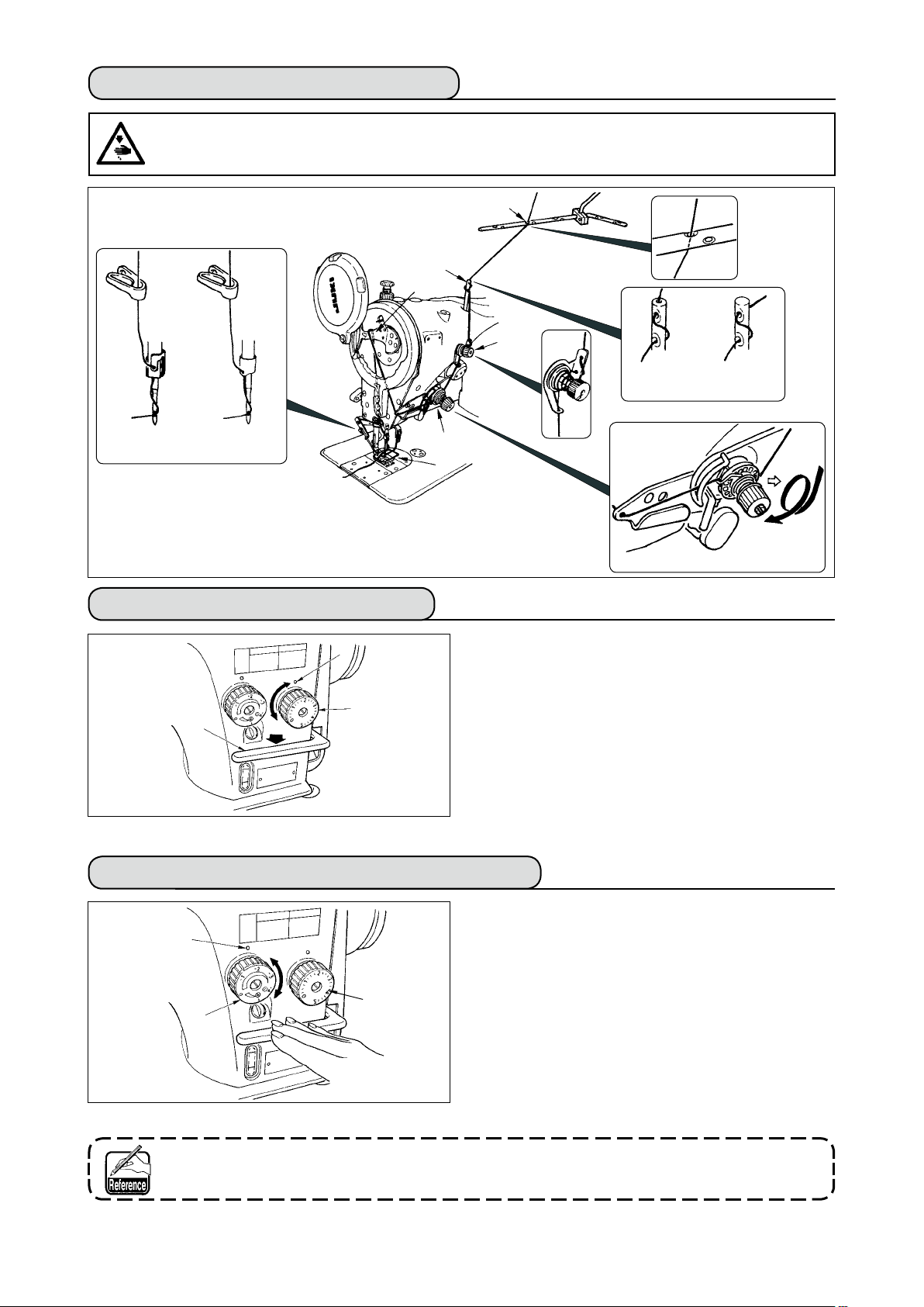
5-5. Threading the machine head ...........................................................................................................17
5-6. Adjusting the stitch length ...............................................................................................................17
5-7. Adjusting the condensation stitching .............................................................................................17
6. HoW To uSE THE oPErATIoN PANEL .................................................................................. 18
6-1. Names and functions of the respective sections ........................................................................... 18
6-2. Before setting the pattern ................................................................................................................20
(1) Limitation of the max. zigzag width ................................................................................................................20
(2) Setting the reference of stitch base line .........................................................................................................
6-3. Basic screen ..................................................................................................................................... 23
6-4. List of the display pictographs of each screen ..............................................................................24
6-5. Setting the sewing pattern ............................................................................................................... 35
(1) Selecting the zigzag pattern .......................................................................................................................... 35
6-6. Setting of the sewing shape ............................................................................................................. 37
(1) 2-step zigzag, 3-step zigzag and 4-step zigzag stitch .................................................................................... 37
(2) Scallop stitching .............................................................................................................................................
(3) Blind stitch sewing ..........................................................................................................................................
(4) Custom pattern stitching .................................................................................................................................
6-7. Reverse feed stitching ......................................................................................................................42
(1) Standard condensation ..................................................................................................................................43
(2) 2-point condensation ......................................................................................................................................
(3) Condensation custom .....................................................................................................................................
(4) Comparison table of the reverse stitch of each shape ...................................................................................
6-8. Selection of the kind of stitching ..................................................................................................... 48
(1) Overlapped stitching ....................................................................................................................................... 48
(2) Programmed stitching ....................................................................................................................................
6-9. Custom pattern .................................................................................................................................. 50
(1) Custom pattern setting ................................................................................................................................... 50
(2) New creation of the custom pattern ...............................................................................................................
(3) Custom pattern edit ........................................................................................................................................
(4) Registration, copy and deletion of the custom pattern ...................................................................................
6-10. Condensation Custom ....................................................................................................................54
(1) Condensation custom setting ......................................................................................................................... 54
(2) Condensation custom edit ..............................................................................................................................
6-11. Pattern stitching ..............................................................................................................................56
(1) Setting the pattern stitching ............................................................................................................................ 56
(2) Registering the pattern stitching .....................................................................................................................
(3) Copy and deletion of the pattern stitching ......................................................................................................
15
22
38
40
41
44
46
47
48
51
52
52
55
57
58
2
4
8
i
Page 3

6-12. Continuous stitching ......................................................................................................................59
(1) New creation of the continuous stitching ........................................................................................................ 60
(2) Continuous stitching edit ................................................................................................................................
(3) Copy and deletion of the continuous stitching ................................................................................................
60
62
6-13. Cycle stitching ................................................................................................................................. 63
(1) New creation of the cycle stitching ................................................................................................................. 63
(2) Cycle stitching edit .........................................................................................................................................
(3) Copy and deletion of the cycle stitching .........................................................................................................
(4) Teaching .........................................................................................................................................................
(5) Performing the constant-dimension stitching using the cycle stitching ..........................................................
63
65
66
67
6-14. Counter ............................................................................................................................................67
(1) Thread trimming counter ................................................................................................................................ 67
(2) Bobbin thread counter ....................................................................................................................................
67
6-15. Information ......................................................................................................................................68
(1) Sewing common data ..................................................................................................................................... 69
(2) Sewing management information ...................................................................................................................
(3) Communication mode ....................................................................................................................................
71
74
6-16. Setting for functions ..................................................................................................................... 78
(1) How to change over to the function setting mode .......................................................................................... 78
(2) Function setting list ........................................................................................................................................
(3) Detailed explanation of selection of functions ................................................................................................
81
85
6-17. External interface .......................................................................................................................... 91
(1) Media slot ....................................................................................................................................................... 91
(2) Ethernet port .................................................................................................................................................. 91
(3) RS-232C port .................................................................................................................................................91
(4) General input port (Production control switch connecting connector) ............................................................ 91
6-18. Setting the maximum sewing speed ........................................................................................... 92
6-19. Panel memory switch setting ....................................................................................................... 92
7. SEWING ...................................................................................................................................... 94
7-1. Adjusting the thread tension ............................................................................................................94
7-2. Adjusting the pressure of the presser foot .....................................................................................95
7-3. One-touch type reverse feed stitching mechanism .......................................................................95
7-4. Hand switch ....................................................................................................................................... 97
8. STANDARD ADJUSTMENT ....................................................................................................... 98
8-1. Adjusting the amount of oil in the hook (LZ-2290A-SS • A-SU (-7) )............................................. 98
8-2. Adjusting the amount of lubricating to face plate section (LZ-2290A-SS•A-SU(-7)) ................... 98
8-3. Adjusting the height of the presser bar .......................................................................................... 99
8-4. Adjusting the micro-lifting mechanism of the presser foot .......................................................... 99
8-5. Height and inclination of the feed dog ............................................................................................99
8-6. Hook adjusting mode ...................................................................................................................... 100
8-7. Attaching / removing the hook .......................................................................................................102
8-8. Adjusting height of the needle bar ................................................................................................ 103
8-9. Adjusting the needle-to-hook timing and the needle guard ........................................................103
8-10. Adjusting the stop position of the needle ...................................................................................104
8-11. Adjusting the thread trimmer .......................................................................................................104
8-12. Adjusting the needle thread feeding device (Thread trimmer type only) ................................ 105
8-13. Adjusting the bird's nest prevention (CB) type wiper ................................................................106
8-14. Replacing procedure of the bird’s nest prevention (CB) type presser knife ........................... 107
9. MAINTENANCE ........................................................................................................................ 108
(1) Replacing the power fuse ............................................................................................................................. 108
(2) Adjusting the contrast of the operation panel display ...................................................................................
(3) Draining (Bird’s nest prevention (CB) type only) ..........................................................................................
(4) Cleaning the dust bag (Bird’s nest prevention (CB) type only) .....................................................................
(5) Cleaning the cooling fan installed on the under cover ..................................................................................
(6) Cleaning the hook section ............................................................................................................................
(7) Cleaning the rear cover of the control box ...................................................................................................
(8) Cleaning the operation panel screen ...........................................................................................................
(9) Replacing procedure of the hook shaft oil wick ............................................................................................
(10) USB port ......................................................................................................................................................111
108
109
109
109
110
110
110
110
10. AT A TIME LIKE THIS ! ........................................................................................................... 112
11. Error DISPLAY
11–1. Error code list (Error display in panel) ....................................................................................... 114
.................................................................................................................... 113
12. TrouBLES AND CorrECTIVE MEASurES ...................................................................... 117
ii
Page 4
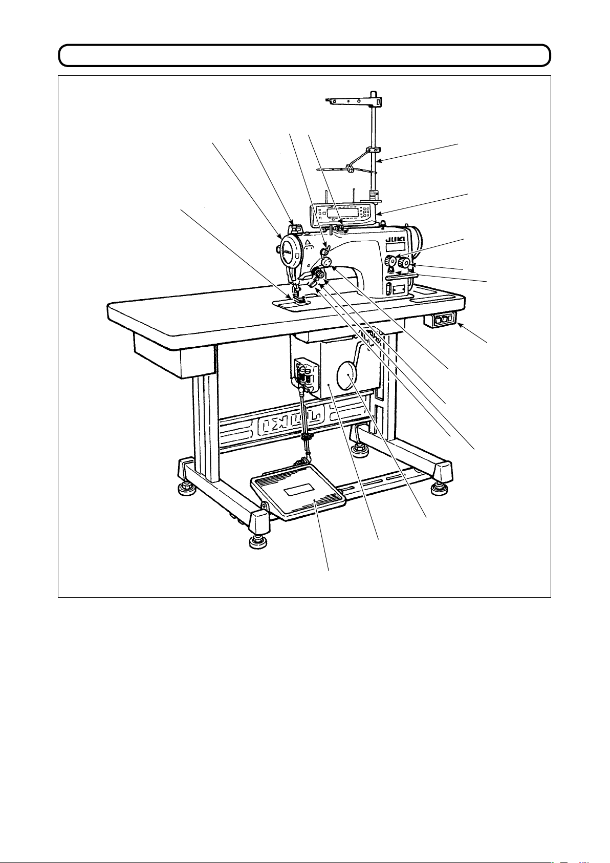
1. NAME oF EACH CoMPoNENT
!5
!4
4
3
2
!6
!3
!2
!1
!7
o
Needle thread draw-out device (LZ-2290A(U)-7)
1
Wiper switch (WB,CB type)
2
Thread take-up cover
3
Finger guard
4
Thread tension controller (Rotary tension)
5
Electrical box
6
Pedal
7
Knee lifter lever
8
Power switch
9
q
t
!0
i
y
u
Hand switch
!0
Stitch length dial
!1
Condensation dial
!2
Operation panel
!3
Bobbin winder
!4
Tension controller No. 1 (Pre-tension)
!5
Thread stand
!6
Oil supply opening
!7
Mirror inversion switch
!8
!8
– 1 –
Page 5
– 2 –
2. SPECIFICATIoNS
2-1. Specications of the machine head
Model LZ-2290A-SS LZ-2290A-SS-7 LZ-2290A-SU LZ-2290A-SU-7
Application Light-weight materials to medium-weight materials
Max. sewing speed 5,000 sti/min (*1) 4,500 sti/min (*1)
Max. zigzag width
Max. feed pitch
Stitch pattern 8 kinds 14 patterns (custom pattern : up to 500 stitches, 20 kinds can be stored.)
Needle SCHMETZ 438, ORGAN DPX5 : #65 to #90
Oil used JUKI New Defrix Oil No. 1
Thread trimmer Without With Without With
Feed method Standard feed Material slippage prevention
Noise - Equivalent continuous emission sound pressure level (L
Model
Application Light-weight materials to medium-weight materials
Max. sewing speed 4,000 sti/min (*1)
Max. zigzag width
Max. feed pitch
Stitch pattern 8 kinds 14 patterns (custom pattern : up to 500 stitches, 20 kinds can be stored.)
Needle SCHMETZ 438, ORGAN DPX5 : #65 to #90
Thread trimmer Without With Without With
Feed method Standard feed Material slippage prevention
Noise - Equivalent continuous emission sound pressure level (L
Minute-quantity
( )
lubricating type
(Dry-head type)
10 mm (*2)
5 mm (stepless ne adjustment) 2.5 mm (stepless ne adjustment)
) at the workstation :
pA
A-weighted value of 80.0 dB; (Includes K
11204 GR2 at 4,500 sti/min.
LZ-2290A-DS LZ-2290A-DS-7 LZ-2290A-DU LZ-2290A-DU-7
5 mm (stepless ne adjustment) 2.5 mm (stepless ne adjustment)
A-weighted value of 80.0 dB; (Includes K
11204 GR2 at 4,500 sti/min.
= 2.5 dB); according to ISO 10821- C.6.2 -ISO
pA
10 mm (*2)
) at the workstation :
pA
= 2.5 dB); according to ISO 10821- C.6.2 -ISO
pA
* 1. The max. sewing speed is limited by the amount of zigzag width per stitch.
Up to 4 mm : 5,000 sti/min (LZ-2290A-SU : 4,500 sti/min, LZ-2290A-DS
•
A-DU (-7) : 4,000 sti/min),
up to 5 mm : 4,000 sti/min, up to 6 mm : 3,500 sti/min, up to 8 mm : 3,000 sti/min
• Properly set the number of revolution in accordance with the product to be sewn and process.
* 2. Max. zigzag width is limited to 8 mm at the time of standard delivery.
2-2. Specications of the electrical box
For general export
■
Supply voltage Single phase 200V / 220V / 240V 3-phase 200V / 220V / 240V
Frequency 50 Hz / 60 Hz
Rated currency 4.6A / 4.3A / 4.0A 3.0A / 2.7A / 2.3A
Operating environment
For CE
■
Supply voltage Single phase 220V / 230V / 240V
Frequency 50 Hz/60 Hz
Rated currency 4.3A / 4.2A / 4.0A
Operating environment
For JUS
■
Supply voltage Single phase 100V / 110V / 120V 3-phase 200V / 220V / 240V
Frequency 50 Hz / 60 Hz
Rated currency 8.0A / 7.5A / 7.0A 3.0A / 2.7A / 2.3A
Operating environment
Temperature : 0 to 40˚C Humidity : 90% or less
Temperature : 0 to 40˚C Humidity : 90% or less
Temperature : 0 to 40˚C Humidity : 90% or less
Page 6
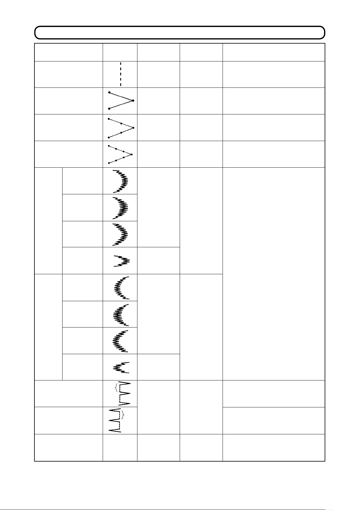
3. STITCH PATTErN TABLE
-
Name of pattern
Straight stitch
2-step zigzag stitch
3-step zigzag stitch
4-step zigzag stitch
Stitch pat
tern
Number of stitches
for pattern
1
2
4
6
Max.zigzag width
—
10
10
10
Remarks
Scallop
(right)
Scallop
(left)
Standard
scallop
Crescent
scallop
Equal-width
scallop
Equal-width
scallop
Standard
scallop
Crescent
scallop
Equal-width
scallop
24
12
24
10
10
Equal-width
scallop
Blind stitch (right)
Blind stitch (left)
Custom pattern
12
a
2+a
a
500
10
10—
– 3 –
Page 7
– 4 –
4. INSTALLATIoN
WArNING :
• Perform the installation of the sewing machine by the technical personnel who have been trained.
• To prevent personal injury, ask our dealer or the electrician for electric wiring.
• Be sure to perform the work with two persons or more when transporting the sewing machine and use a
lorry when moving it.
• To prevent personal injury caused by abrupt start of the sewing machine, do not connect the power plug
until the set-up of the sewing machine is completed.
• Be sure to earth the ground wire to prevent personal injury caused by leak.
• Be sure to attach safety protection cover, nger guard, etc.
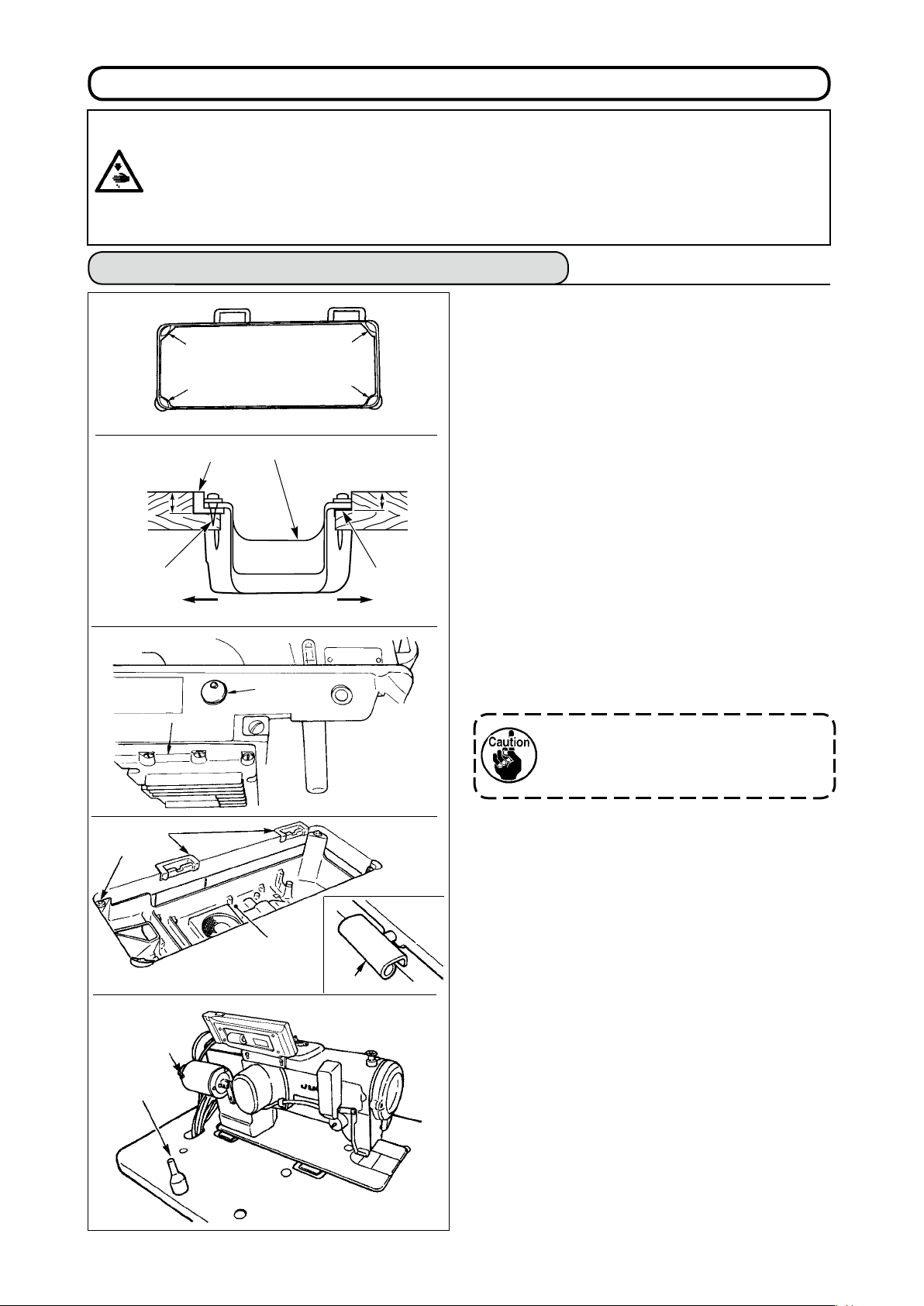
4-1. Installation of the sewing machine head
Installing the under cover
■
1) The under cover should rest on the four corners
3
3
of the machine table groove.
23.5 mm
3
2
8
7
1
1
A
5
4
B
1
19.5 mm
3
2) Fix two rubber seats
side) using nails
on side
1
as illustrated above. Fix two
2
(operator’s
A
cushion seats 3 on side B (hinged side) using a
rubber-based adhesive. Then place under cover
on the xed seats.
4
3) Remove air vent cap
bed. (Be sure to attach cap
attached to the machine
5
when transporting
5
the machine head in the state that the machine
head is removed from the machine table.)
If the sewing machine is operated without removing air vent cap 5, oil leakage
from gear box portion 7 may occur.
4) Fit hinge
into the opening in the machine bed,
1
and t the machine head to table rubber hinge 8
before placing the machine head on cushions 3
on the four corners.
6
9
4
1
5) Attach head support rod
to the machine table.
6
(However, this step is not necessary for the ma
chine with AK
device.)
9
-
Page 8
4-2. Removing the needle bar stopper
1
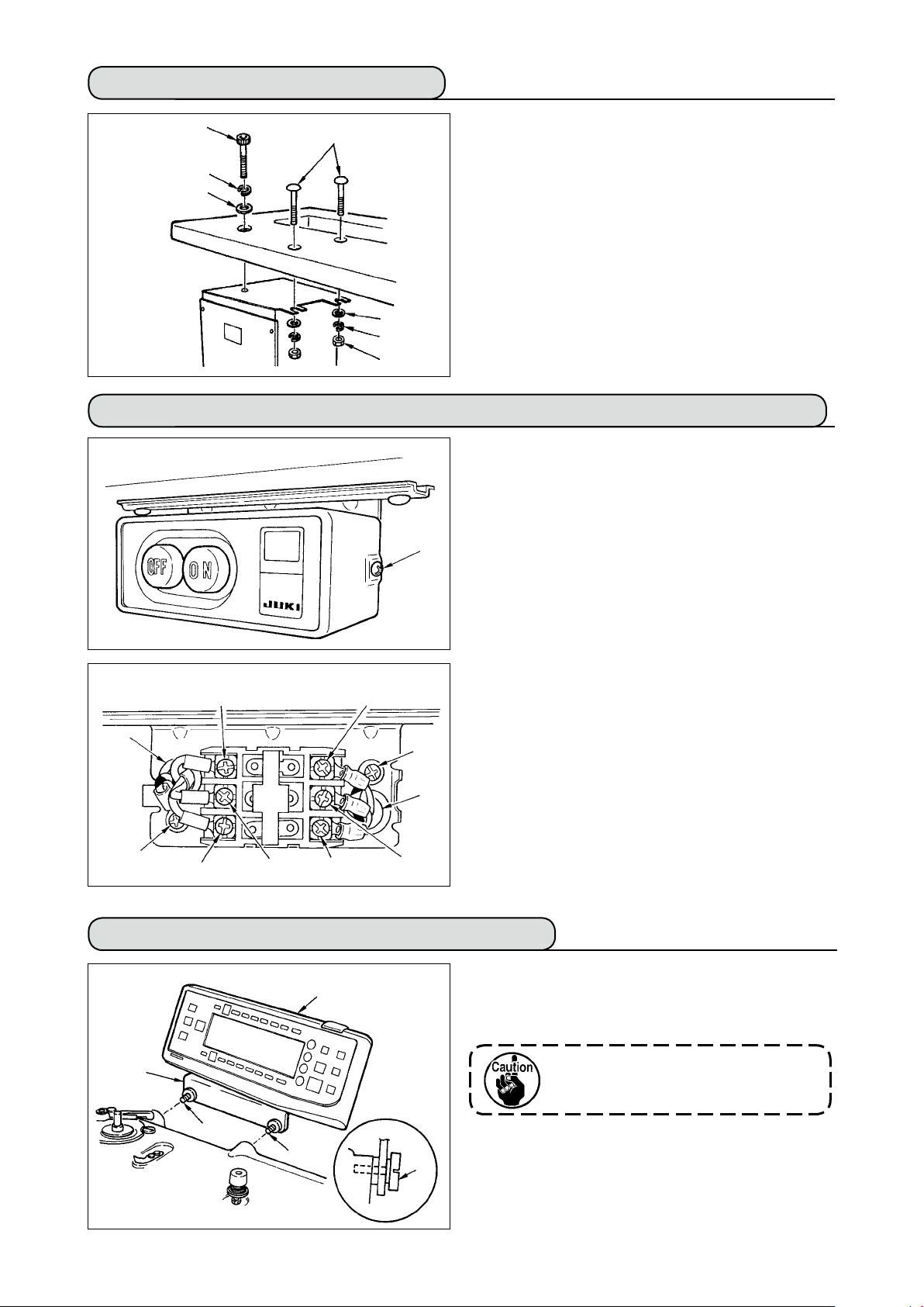
4-3. Attaching the knee-lifter
220 mm
Remove needle bar stopper
Keep the needle bar stopper which has
been removed, and install this needle
bar stopper when transporting the sewing machine. The needle bar stopper
may be cut when it is strongly drawn
out. Slightly move the needle bar to
the right or left and slowly draw out the
needle bar stopper.
Insert knee lifter pad
into attaching hole
1
for transportation.
1
2
and
tighten it with bolt 3.
* Adjust the position of knee lifter pad 1 to a con-
venient place. For the reference dimension, the
position is 220 mm from the bottom face of table.
2
1
3
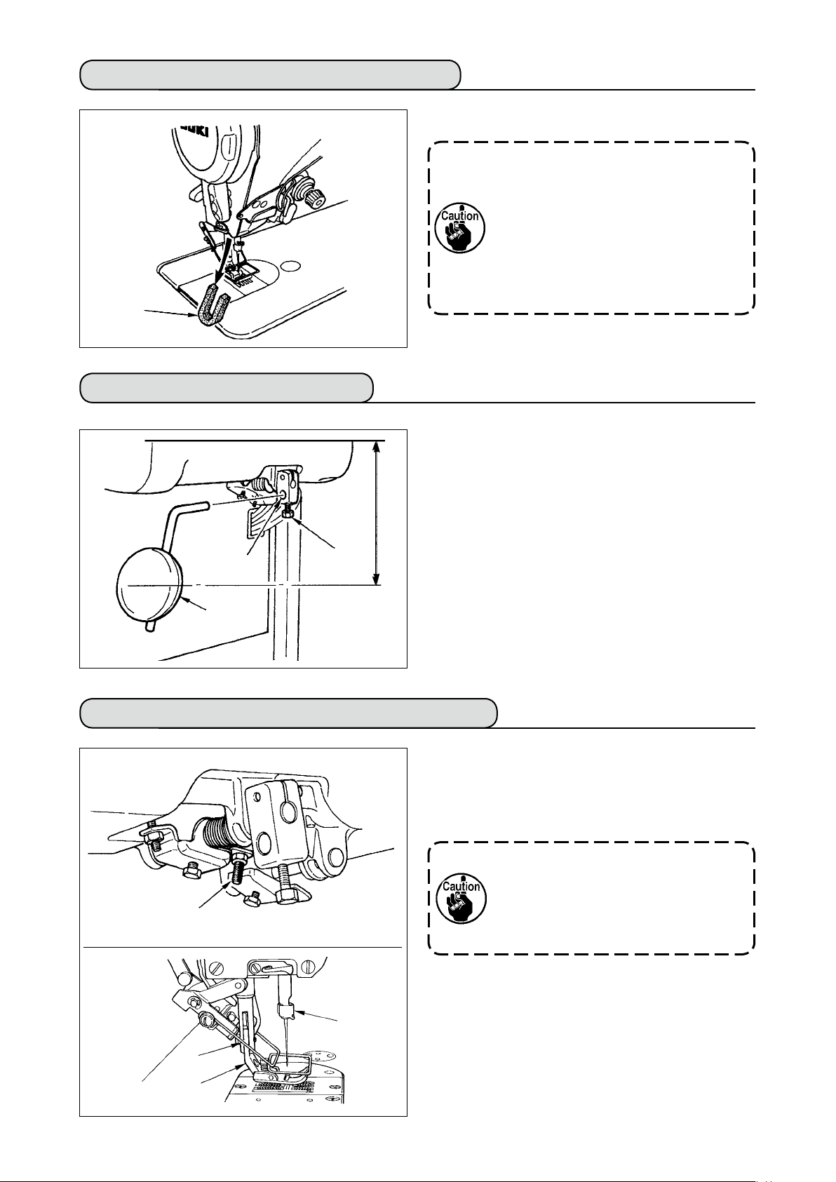
4-4. Adjusting the height of the knee lifter
1) The standard height of the presser foot lifted us-
ing the knee lifter is 10 mm.
2) You can adjust the presser foot lift using knee
lifter adjust screw 1.
1
Do not operate the sewing machine in
the state that presser foot 3 is lifted by
10 mm or more since needle bar 2 and
presser foot 3, or wiper 4 and presser
foot 3 come in contact with each other.
4
2
3
– 5 –
Page 9
– 6 –
4-5. Installing the electrical box
5
1
6
7
Install the electrical box on the under side of the
table using round-head bolts
spring washers 3 and nuts
chine at the location illustrated, and using bolt having
hexagonal indentation on the head
and plain washer 7 supplied with the machine at
6
the location illustrated.
2
3
4
4-6. Connecting the power switch cord
1) Loosen screw 1 located on the side of the power
2) Connecting the input power cord of electrical box
When the input power cord of electrical box is 4P
¡
1
8
6
9
B
7
2
A
5
4
3
Put 4P cord from hole A of the power switch and
securely x green/yellow cord to
black cord to 3 and red cord to
When the input power cord of electrical box is 3P
¡
Put 3P cord from hole A of the power switch and
securely x green/yellow cord to 5, brown cord to
2
3) Connecting the power cable supplied as accessories
In case of 3-phase power cable
¡
Put power cable from hole B of the power switch, and
In case of single phase power cable
¡
Put power cable from hole B of the power switch,
4) Installing the power switch cover
Securely tighten screw 1 located on the side of
, plain washers
1
supplied with the ma
4
, spring washer
5
2
,
-
(Japan and general export area)
switch supplied as accessories and remove the
power switch cover.
, white cord to
5
with screws.
4
and sky blue cord to 3 with screws.
securely x green/yellow cord to 9, white cord to 6,
black cord to 7 and red cord to 8 with screws.
and securely x green/yellow cord to 9 and other
cords to 6 and 7 with screws. 8 is not used.
the power switch.
2
,
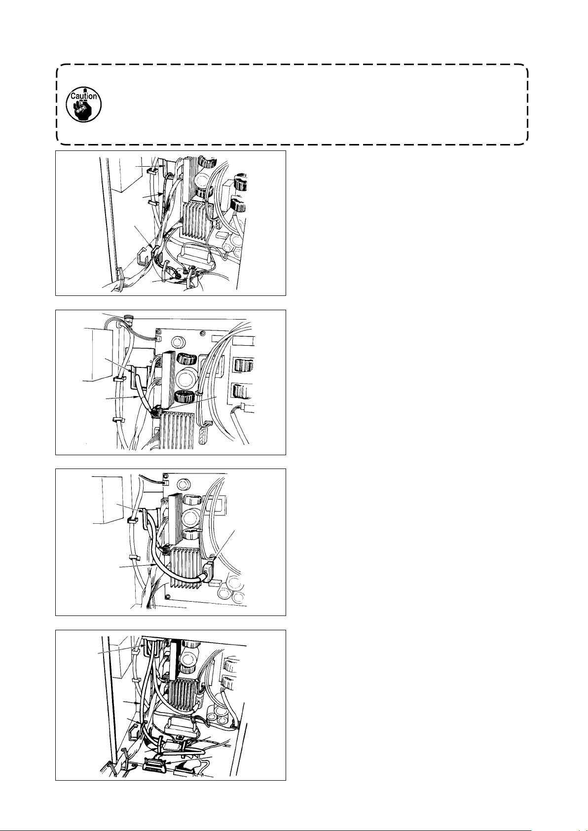
4-7. Installing the operation panel (IT-100D)
1
2
3
3
3
1) Install operation panel
using screws 3 which have been assembled to
panel installing bracket
on the machine head
1
.
2
Do not disassemble the operation
panel to prevent it from breakage.
Page 10
4-8. Connecting the cords
WArNING :
• To prevent personal injury caused by abrupt start of the sewing machine, carry out the work after turning
OFF the power switch and a lapse of 5 minutes or more.
• To prevent damage of device caused by maloperation and wrong specications, be sure to connect all the
corresponding connectors to the specied places.
• To prevent personal injury caused by maloperation, be sure to lock the connector with lock.
• As for the details of handling respective devices, read carefully the Instruction Manuals supplied with the
devices before handling the devices.
(1) Preparation of wiring
A
1) Pass the cords coming from the machine head to
the underside of the table through hole A in the
table.
D
2) Loosen screws D and lift cord presser plate C of
cord passing hole B located on the front cover to
B
C
the top and temporarily tighten the plate.
3) Remove four screws E xing the rear cover of
the electrical box. When opening the rear cover,
pressing it with your hands, slowly open it by ap
-
proximately 90˚ until it stops as illustrated.
E
Slowly
Be sure to lend your hand to the rear
cover in order not to let the rear cover
fall. In addition, do not apply force to the
rear cover opened.
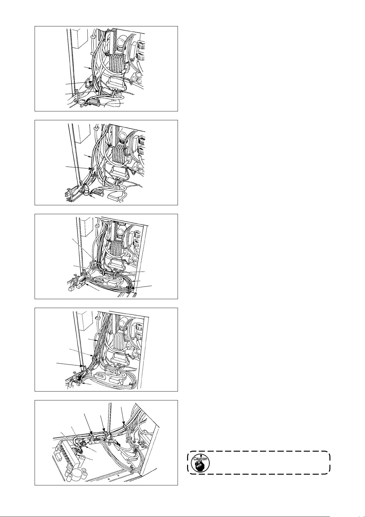
4) Remove the locks of cord clamps a, b, c, d, e, and f.
b
a
e
f
c
d
How to remove the cord clamp
1
Lightly pressing
1
Pull down the clamp.
2
The clamp goes up.
3
3
2
1
* See P.11 for how to lock the cord clamp.
– 7 –
Page 11
– 8 –
(2) Connecting the connectors
• Each connector has the inserting direction. Check the direction and securely insert it. (In
case of the type with lock, insert up to the lock.)
• If the connector is forcibly inserted, trouble or accident will be caused.
• Never pull out the connectors inserted at the time of delivery.
• The sewing machine fails to work if the connectors are not properly inserted. Not only the
problem such as the error warning or the like but also breakage of the sewing machine or
electrical box will occur.
B
1
b
2
B
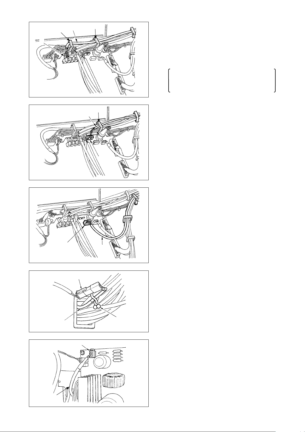
Connect cords in the following order.
5) Insert yellow/green earth cord
coming from
1
the machine head inside the electrical box
through front cover through hole B, and pass it
through cord clamp “b” as illustrated and tighten
it with screw at the position 2 in the illustration.
6) Insert white square connector 9P black cord 3
coming from the machine head inside the electri
cal box through front cover through hole B, and
insert it into connector CN38 4 of the circuit
board attached to the front cover.
-
3
4
7) Insert white connector 4P black cord 5 coming
from the machine head inside the electrical box
B
through front cover through hole B, and insert it
into connector CN21 6 of the circuit board at-
6
5
tached to the front cover.
8) Insert white connector 26P cord 7 coming
B
from the operation panel inside the electrical
box through front cover through hole B, pass it
through cord clamps “b”, “c” and “d”, insert it into
u
b
connector CN34 8, and lock it.
d
c
i
Page 12
9) Insert black connector 4P white cord
coming
9
from the machine head inside the electrical box
through front cover through hole B, and insert it
into connector CN31
o
b
c
!0
!0
.
10) Insert gray round connector 7P cord
!1
com-
ing from the machine head inside the electrical
box through front cover through hole B, pass it
through cord clamp “a”, and insert it into connec-
!1
a
!2
tor CN30 !2.
11) Insert white connector 12P cord
coming from
!3
the machine head inside the electrical box through
b
front cover through hole B, pass it through cord
clamps “b”, “c”, “d” and “g”, and insert it into con
-
nector CN53 !4.
c
d
!3
g
!4
Close cord clamps “b”, “c” and “d”.
12) Insert white connector 6P three cords !5 com-
ing from the machine head inside the electrical
box through front cover through hole B, pass it
!5
a
e
!6
a
!7
!8
f
e
through cord clamps “a” and “e”, and insert it into
connector CN54 !6.
13) Insert white connector 10P cord !7 and blue
connector 2P cord
coming from the machine
!8
head inside the electrical box through front cover
through hole B, pass them through cord clamps
“a”, “e” and “f”, and insert the white 10P into con-
!9
@0
nector CN51
The blue 2P connector is attached only
for the machine with thread trimmer.
and the blue 2P into CN46
!9
@0
.
Close cord clamps “a”, “e” and “f”.
– 9 –
Page 13
– 10 –
@2
@1
f
e
a
When the Auto-lifter (AK121) is used :
14) Insert white connector 2P cord
coming from
@
1
the machine head inside the electrical box
through front cover through hole B, pass it
through cord clamps “a”, “e” and “f”, and insert it
into connector CN40
@2
.
Change the setting of function setting No.
23 from “0” to “1” after completing all set-up
procedure. For the details, see p.78 and p.81.
@6
@3
e
a
When the bird’s nest prevention device is used
(CB type)
15) Insert white small connector 6P cord
@3
com-
ing from the machine head inside the electrical
box through front cover through hole B, pass
it through cord clamps “a” and “e”, and insert it
into connector CN52 @4.
@4
When foot pedal for standing work (PK70 or 71) is
b
c
used :
16) Insert black connector 12P cord
inside the
@5
electrical box through front cover through hole
B coming from the foot pedal for standing work,
pass it through cord clamps “b” and “c”, and
insert it into connector CN32
@5
@6
.
@7
@7
@8
#0
@9
17) Connect white connector 2P of cord @7 sup-
plied as accessories to which red connector 2P
and white connector 2P are attached to white
connector 2P
of under cover of the machine
@8
head.
Fix omega lock
supplied as accessories with
@9
the neighboring cords and cord @7 as shown in
the gure.
18) Insert red connector 2P side of cord
as accessories to which red connector 2P and
white connector 2P are attached inside the elec
trical box through front cover through hole, and
insert it into red connector CN25 #0.
supplied
@7
-
Page 14
How to lock the cord clamp
When the insertion of the connector is completed,
lock the cord clamps.
4
Lightly press the corner of clamp.
4
(Cord clamp is locked with a click.)
2
C
1
B
A
4
3
Clamp
4-9. Attaching the connecting rod
3
Take care so that the cord is not caught between
q
the rear cover and the electrical box main body,
close the rear cover while pressing section A on
the lower side of the rear cover, and tighten four
screws 1.
Press down cord presser plate C of cord through
w
hole B of the front cover, press the cord, and
tighten screws 2.
1) Fix connecting rod
lever
with nut
2
2) Installing connecting rod
to installing hole
1
.
3
to installing hole A
1
of pedal
B
will lengthen the pedal depressing stroke, and the
pedal operation at a medium speed will be easier.
2
1
B
A
4-10. Adjustment of the pedal
2
1
3
4
Installing the connecting rod
■
1) Move pedal 3 to the right or left as illustrated by
the arrows so that motor control lever 1 and con-
necting rod 2 are straightened.
Adjusting the pedal angle
■
1) The pedal tilt can be freely adjusted by changing
the length of the connecting rod.
2) Loosen adjust screw 4, and adjust the length of
connecting rod 2.
– 11 –
Page 15
– 12 –
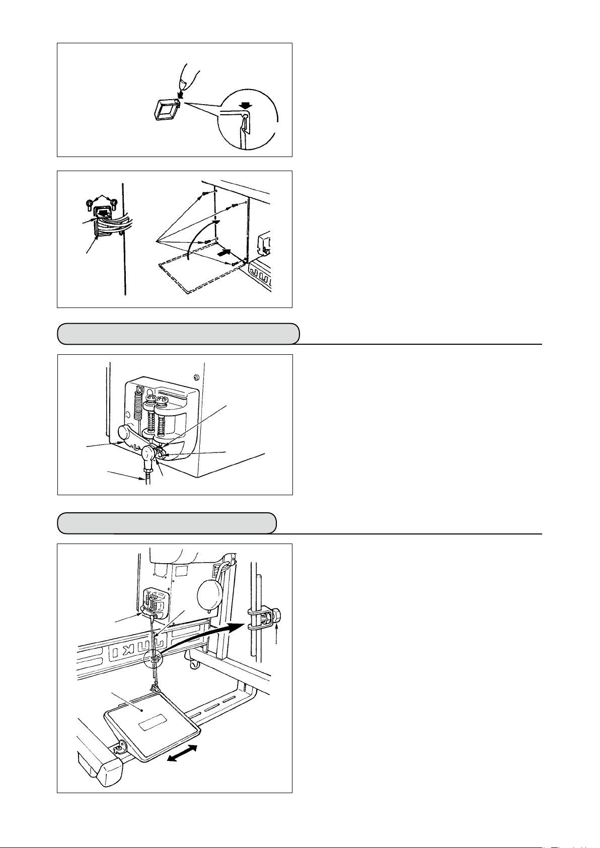
4-11. Installing the thread stand
1) Assemble the thread stand unit, and insert it in
the hole in the machine table.
2
2) Tighten locknut 1 to x the thread stand.
3) For ceiling wiring, pass the power cord through
spool rest rod 2.
1
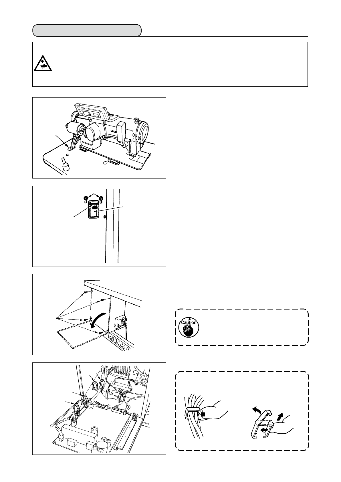
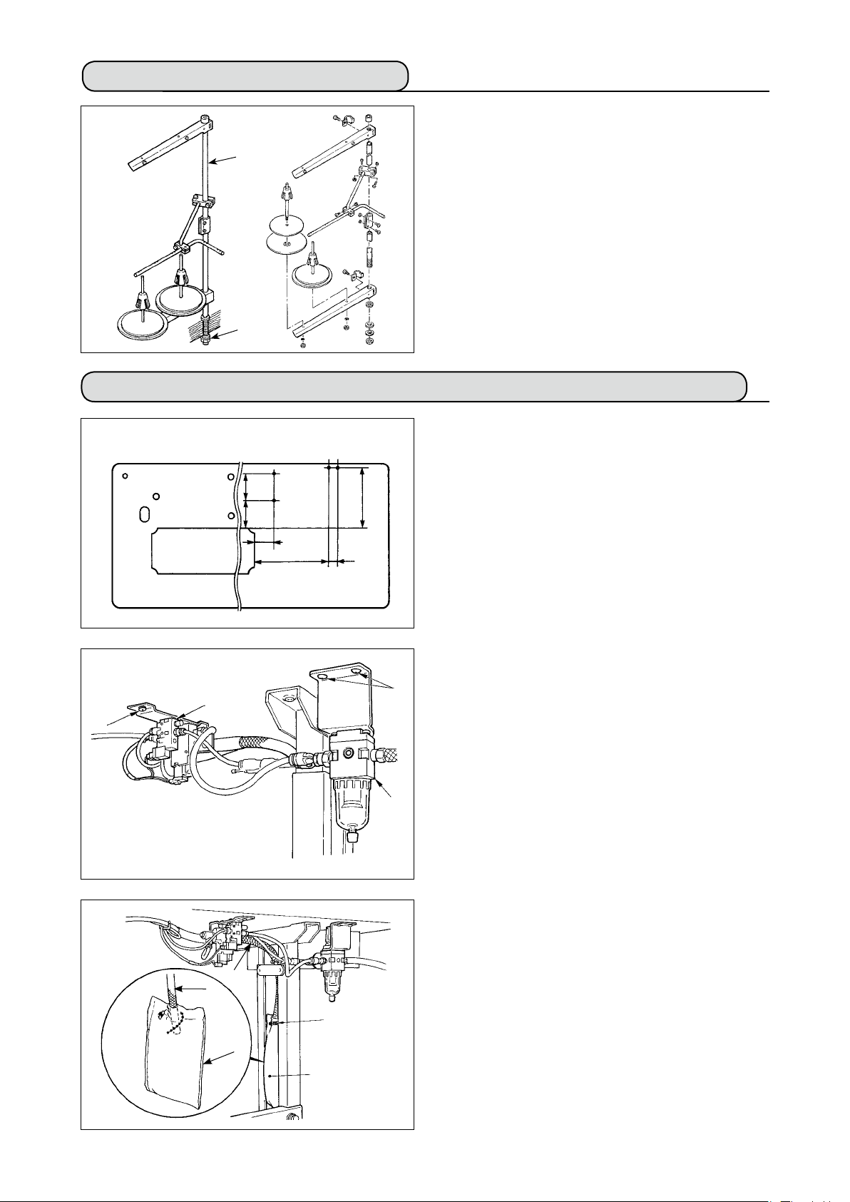
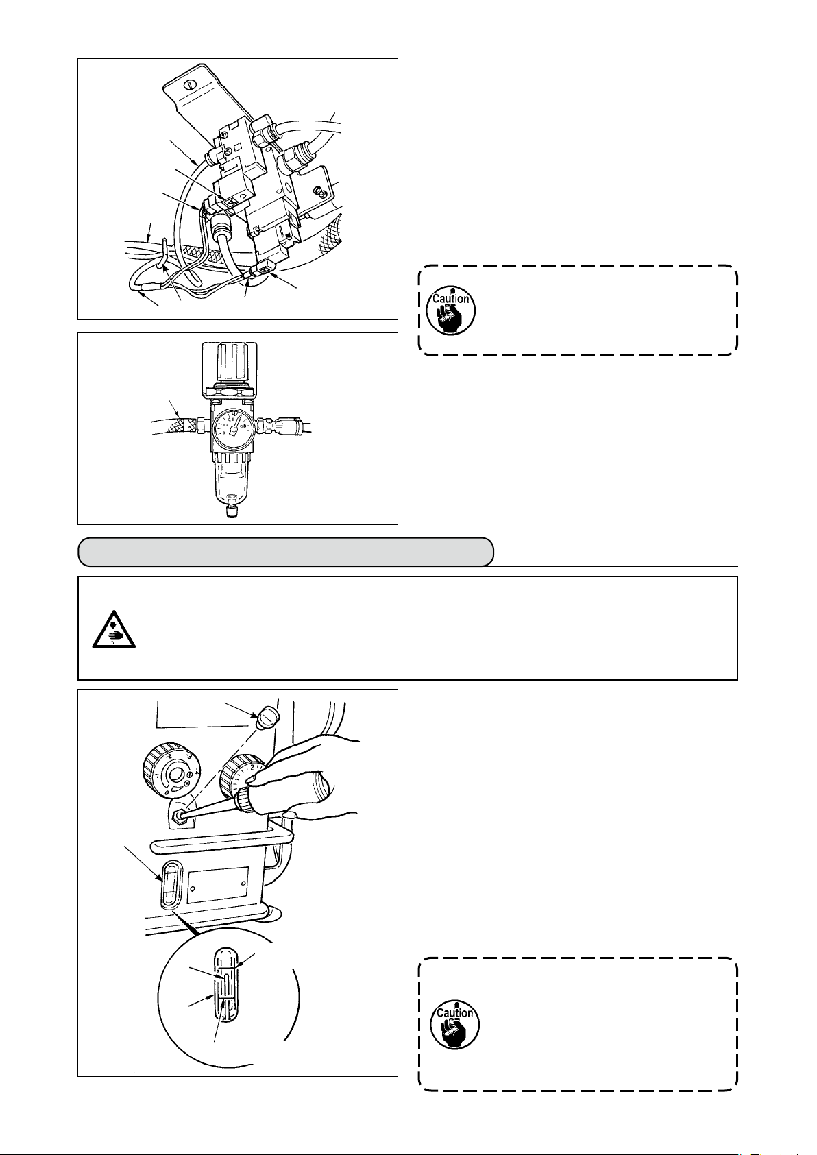
4-12. Installing the bird’s nest prevention (CB) type sewing machine
(bottom surface of the machine table)
106107
75
291
1
2
34
(mm)
233
3
4
1) Punch dots on the positions of the setscrews of
solenoid valve (asm.) and regulator (asm.) on the
bottom surface of the machine table.
Besides, awling is performed on JUKI genuine
table.
2) Fix solenoid valve (asm.)
with wood screw
1
2
supplied with the sewing machine as accesso-
ries.
3) Fix regulator (total asm.)
with wood screw
3
4
supplied with the sewing machine as accesso-
ries.
4) Connect ø6 and ø8 hoses attached to regulator
(total asm.)
to the respective solenoid valves.
3
9
9
5
5
6
5) Insert dust bag 5 into the top end of hose
dust bag and x it with band
supplied with the
6
sewing machine as accessories.
9
for
Page 16
ø 8
ø 4
!1
7
!0
8
!1
!0
6) Adjust solenoid valve cord (asm.) 7 to the solenoid valve and the hot marker of the cord, and
connect it.
Connect 6P connector
to CM52 connector
!0!1
inside the electrical box.(Refer to “When the bird’
s nest prevention device is used, p. 10".)
7) Connect air hose ø4 coming from the machine
head to the solenoid valve section and air hose
ø8 to the dust bag suction port respectively.
8) Fix the solenoid valve and the air hose on the
table with staple
1. Fix the staple to such an extent that
the air hose is not crushed.
2. Determine the position of the staple
so that the cord and the air hose do
not hang from the table.
supplied as accessories.
8
9) Connect the air pipe
!2
to 0.6 MPa.
4-13. Lubrication (LZ-2290A-SS • A-SU (-7) )
WArNING :
1. Do not connect the power plug until the lubrication has been completed so as to prevent accidents due to abrupt start of the sewing machine,
2. To prevent the occurrence of an inammation or rash, immediately wash the related portions if
oil adheres to your eyes or other parts of your body.
3. If oil is mistakenly swallowed, diarrhea or vomitting may occur. Put oil in a place where children
cannot reach.
Fill the oil tank with oil for hook lubrication before
operating the sewing machine.
1) Remove oil hole cap 1 and ll the oil tank with
JUKI New Defrix Oil No. 1 using the oiler supplied
with the machine.
2) Fill the oil tank with oil up to the place where the
top of oil amount indicating rod 3 aligns with
the upper engraved line of oil amount indicating
window 2. If the oil is lled excessively, it will
leak from the air vent hole in the oil tank or proper
lubrication will be not performed. So, be careful.
3) When you operate the sewing machine, rell oil if
the top end of oil amount indicating rod 3 comes
down to the lower engraved marker line of oil
amount indicating window 2.
2
1
3
2
Upper engraved
marker line
Lower engraved
marker line
and set the air pressure
!2
• When you use a new sewing ma
chine or a sewing machine after an
extended period of disuse, run your
machine at 3,000 to 3,500 sti/min for
the purpose of break-in.
• For the oil for hook lubrication, pur
chase JUKI New Defrix Oil No. 1 (Part
No. : MDFRX1600C0).
-
-
– 13 –
Page 17
– 14 –
4-14. Test run
(1) Turn ON the power
WArNING :
• Check again the power voltage before connecting the power cord.
• Check that the power switch is turned OFF and connect the power cord to the power receptacle.
• Be sure to connect the earth wire.
• In case where the buzzer keeps beeping immediately after turning ON the power, there is a possi
bility of the wrong connection of cord or wrong power voltage. Turn OFF the power.
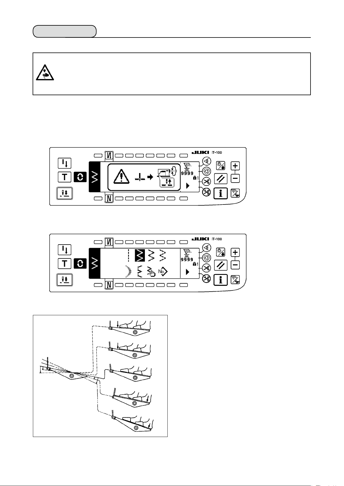
1) When the needle bar is in its UP position, zigzag origin detection is performed.
2) When the needle bar is in the position other than UP position :
Display as shown in the gure below appears. Turn the handwheel to bring the needle bar to needle UP
position and the display changes to the next screen. Then the needle moves left and right, and zigzag
origin detection is performed.
-
(2) How to operate the pedal
h
A
B
C
D
E
The pedal is operated in four stages.
1) Lightly depress the front part of the pedal for lowspeed operation
2) Further depress the front part of the pedal for
high-speed operation A. (Note that the sewing machine will enter the high-speed operation
mode after the completion of reverse feed stitching if the automatic reverse feed stitching function
is specied with the corresponding switch.)
3) Bring the pedal back to its neutral position, and
the sewing machine will stop running C.
(The needle stops in the highest / lowest posi-
tion.)
4) Strongly depress the back part of the pedal, and
the thread trimmer will be actuated E.
Lightly depress the back part of the pedal, and
the presser foot will go up D. Further depress the
back part of the pedal, and the thread trimmer will
be actuated.
B
.
Page 18
5.
PrEPArATIoN BEForE SEWING
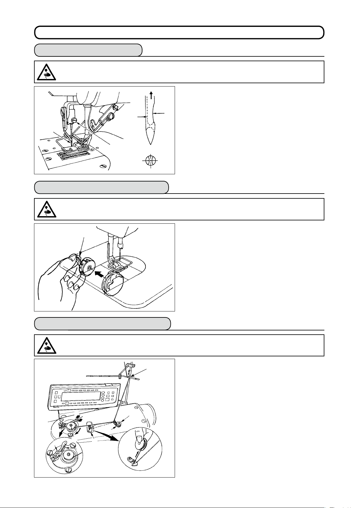
5-1. Inserting the needle
WArNING :
To protect against possible personal injury due to abrupt start of the machine, be sure to start the
following work after turning the power off and ascertaining that the motor is at rest.
B
1
2
A
5-2. Removing the bobbin case
WArNING :
To protect against possible personal injury due to abrupt start of the machine, be sure to start the
following work after turning the power off and ascertaining that the motor is at rest.
1) Turn the handwheel by hand to raise the needle
to its highest position.
2) Loosen the needle clamp screw 2 . Hold the nee-
dle 1 so that the long groove
on the needle is
B
facing exactly toward you.
3) Insert the needle deep into the hole of the needle
bar in the direction of the arrow until it will go no
further.
4) Securely tighten the screw 2 .
5) Conrm that the long groove B on the needle
faces toward you.
1
5-3. Winding the bobbin thread
WArNING :
To protect against possible personal injury due to abrupt start of the machine, be sure to start the
following work after turning the power off and ascertaining that the motor is at rest.
1
7
5
B
A
C
6
2
8
3
1) Turn the handwheel by hand to raise the needle
to its highest position.
2) Raise bobbin case latch 1 and remove the bob-
bin case.
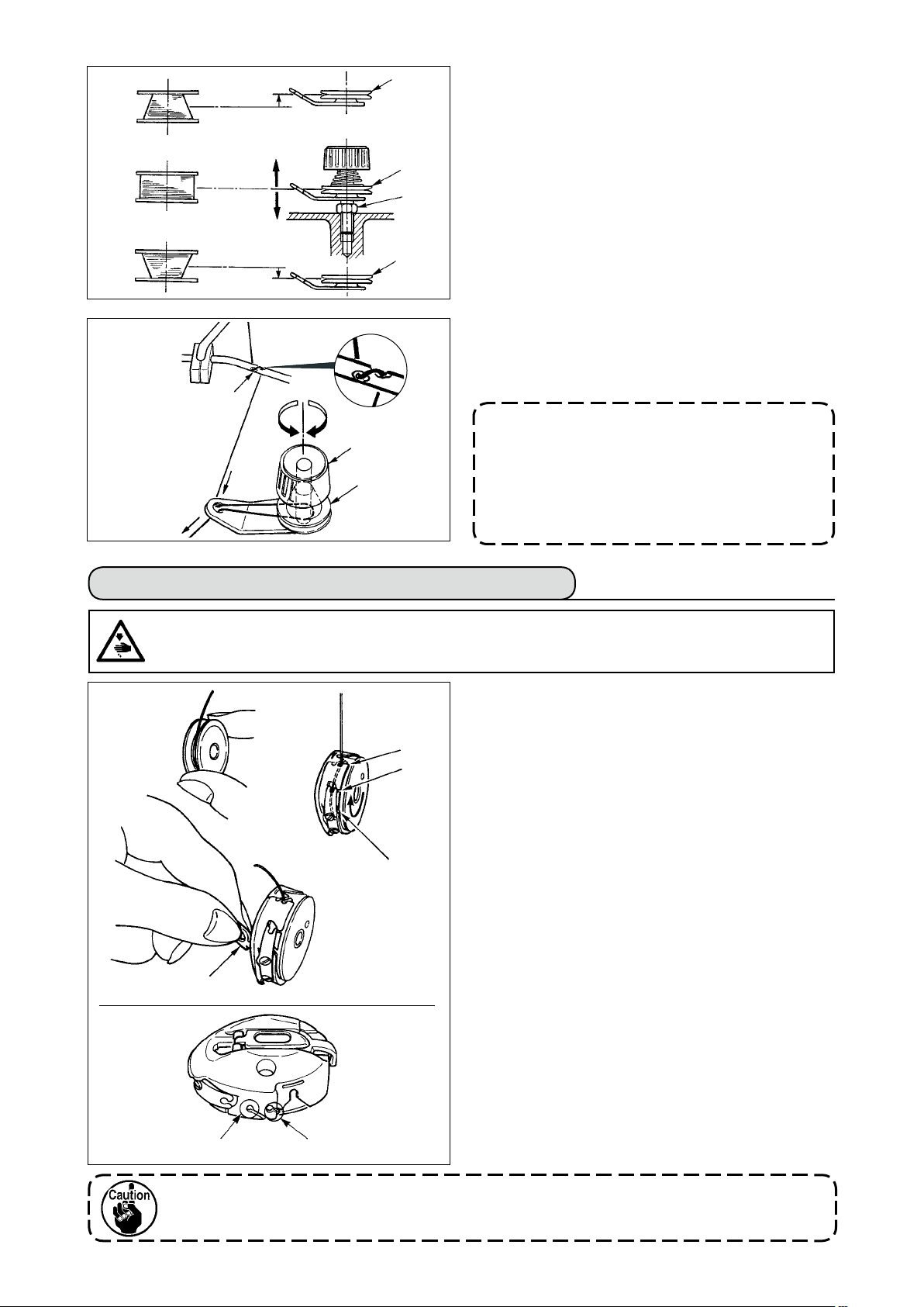
1) Insert the bobbin deep into the bobbin winder
spindle
2) Pass the bobbin thread pulled out from the spool
rested on the right side of the thread stand following
the order from 1 as shown in the gure on the left.
Then, wind the end of the bobbin thread on the bob
bin several times.
3)
Press the bobbin winder adjusting plate 6 in the
direction of A and start the sewing machine. The bob
bin rotates in the direction of C and the bobbin thread
is wound up. The bobbin winder spindle
matically stop as soon as the winding is nished.
4) Remove the bobbin and cut the bobbin thread with
the thread cut retainer
5)
To adjust the winding amount of the bobbin thread, loosen
setscrew 7 and move bobbin winder adjusting plate 6
to the direction of A or B. Then, tighten setscrew
To the direction A : The amount is decreased.
To the direction B : The amount is increased.
until it will go no further.
5
.
8
will auto-
5
7
.
-
-
– 15 –
Page 19
– 16 –
(Threading)
1
2
6) In case that the bobbin thread is not wound
evenly on the bobbin, loosen the nut 4 and turn
the bobbin thread tension to adjust the height of
the thread tension disk 2.
A
2
4
• It is the standard that the center of the bobbin is
as high as the center of the thread tension disk.
• Move the position of the thread tension disk 2 to
the direction A as shown in the gure on the left
B
2
when the winding amount of the bobbin thread on
the lower part of the bobbin is excessive and to
the direction B as shown in the gure on the left
when the winding amount of the bobbin thread on
the upper part of the bobbin is excessive.
After the adjustment, tighten the nut 4 .
7) Turn the thread tension nut 3 to adjust the tension of the bobbin thread winder.
Note 1. When winding bobbin thread, start winding
3
2. When winding bobbin thread in the state
2
in the state that the thread between bobbin
and thread tension disk 2 is tense.
that the sewing is not performed, remove
needle thread from the thread path of the
thread take-up and remove bobbin from the
hook.
5-4. Placing the bobbin case and the bobbin
WArNING :
To protect against possible personal injury due to abrupt start of the machine, be sure to start the
following work after turning the power off and ascertaining that the motor is at rest.
1) Turn the handwheel by hand to raise the needle
to its highest position.
2) Take a bobbin by your right hand with the thread
drawn out about 5 cm from the thread end of the
bobbin and place it into the bobbin case as illustrated.
3)
Thread the bobbin case in the order of the numbers
and pull it out through the thread path as illustrated.
The bobbin rotates in the bobbin case in the direction
shown by arrow when bobbin thread is drawn.
4) Raise bobbin case latch 1 and hold it between
your two ngers as shown in the gure on the left.
5) Insert the bobbin case into the sewing hook shaft
as far as it will go by putting your hand from the
under cover of the inner hook. (Click sounds.)
6) Release the bobbin case latch to let it steadily
rest in the closing position.
How to use the bobbin case thread hole
■
1) Use hole A mainly for zigzag stitches other than
2-step zigzag stitch and scallop zigzag stitch.
2) Use hole B mainly for 2-step zigzag stitch and
scallop zigzag stitch.
1
3
2
1
B
A
There may be a case where several stitches at the start of sewing are difcult to be knotted
when thread trimmer is used with thin lament thread such as (#50, #60 or #80) using hole B.
At this time, use the other hole or perform the sewing starting from the right.
Page 20
5-5. Threading the machine head
WArNING :
To protect against possible personal injury due to abrupt start of the machine, be sure to start the
following work after turning the power off and ascertaining that the motor is at rest.
5
2
3
1
LZ-2290A-7
With thread
trimmer
LZ-2290A
Without thread
trimmer
With auxiliary
thread take-up
1) Turn the handwheel by hand to bring the needle to the most raised position.
2) Pass the thread in the order of the numbers as illustrated.
3) Pull out the thread about 10 cm from the needle after passing it through the needle.
Without auxiliary
thread take-up
4
6
5-6. Adjusting the stitch length
A
1
2
1) Turn the stitch length dial 1 in the direction of
the arrow so that the number corresponding to
the desired stitch length meets the marker dot A
engraved on the machine arm.
2)
Numbers on the stitch length dial are calibrated in mm.
3) To perform reverse feed stitching, press down the
feed lever 2 . The sewing machine performs reverse feed stitching as long as you keep the feed
lever held pressed. The feed lever will return to its
home position and the sewing machine will run in
the normal stitching direction when you release
the feed lever.
5-7. Adjusting the condensation stitching
Turn the thread
once.
Stitch length can be reduced at the start or end of
B
sewing. This feature is used for fastening stitch.
1) Turn condensation stitching adjusting dial
3
in
the direction of the arrow mark, and adjust the de
3
1
sired number to engraved dot
arm.
2)
The number of the graduation is shown in the unit of mm.
3)
Turn condensation stitching adjusting dial
on the machine
B
in the
3
direction of + to reduce the reverse feed stitch length.
Example : When stitch length dial 1 is used with the
graduation of +2, the maximum adjustment value
of condensation stitching adjusting dial
3
becomes -2. (It is possible to adjust within the range
of -2 to +2.)
Maximum feed amount is regulated to ±2 according to the gauge delivered (feed dog :
22581508). Adjustment can be performed up to the range of maximum +5 to -4 by replacing the
gauge (feed dog : 22540009).
4) Note that the graduations on the dial are mere reference. Adjust the condensation stitching while actu-
ally observing the nished seam.
– 17 –
-
Page 21
– 18 –
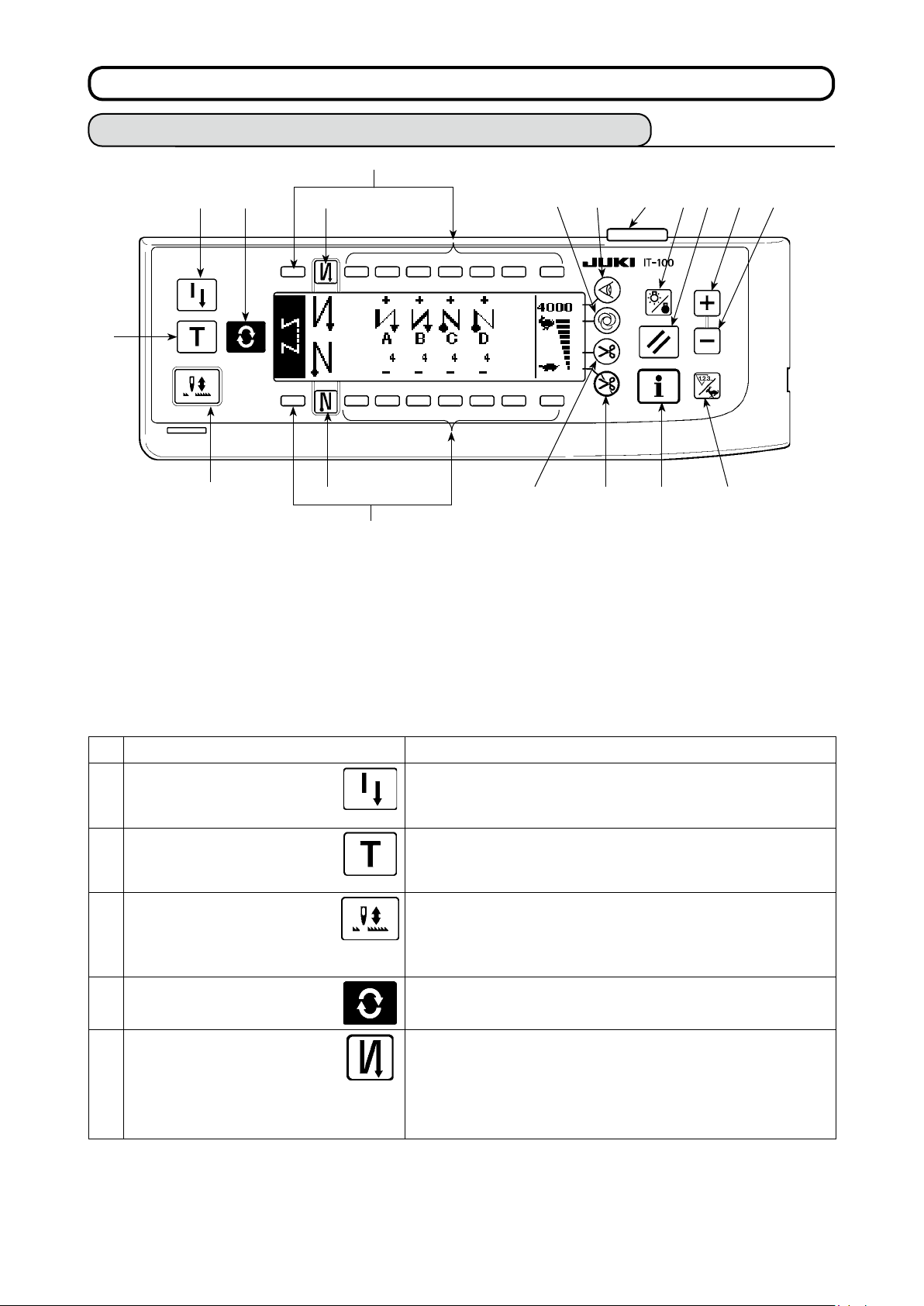
6. HoW To uSE THE oPErATIoN PANEL
6-1. Names and functions of the respective sections
!7
1 4 5
2
3
!7
Re-sewing switch
1
Teaching switch
2
Needle up/down compensating switch
3
Screen changeover switch
4
With/without reverse feed stitch at sewing start switch
5
With/without reverse feed stitch at sewing end switch
6
Material edge sensor switch
7
One-shot automatic sewing switch
8
With/without automatic thread trimmer switch
9
7
8
96
Thread trimming prohibiting switch
!0
Backlight switch
!1
Reset switch
!2
Information switch
!3
+ switch
!4
– switch
!5
Counter/speed changeover switch
!6
General-purpose switch
!7
Power display lamp
!8
!1 !2 !4 !5
!8
!6!3!0
Re-sewing switch
1
Teaching switch
2
Needle up/down compensating switch
3
Screen changeover switch
4
With/without reverse feed
stitch at sewing start switch
5
Switch Description
This switch is used to continue sewing from the step on the
way after replacing bobbin thread when bobbin thread has
run out during program stitching step.
This is the switch to set the setting of the number of stitches
with the value of number of stitches which has been actually sewn.
This is the switch to perform needle up/down compensating
stitching. (Needle up/down compensating stitching and one
stitch compensating stitching can be changed over with function
setting No. 22.)
This is the switch to change over the screen.
This is the switch to turn ON/OFF automatic reverse feed
stitch at sewing start.
* This switch cannot be used with the sewing machine
which is not provided with automatic reverse feed stitching device.
Page 22
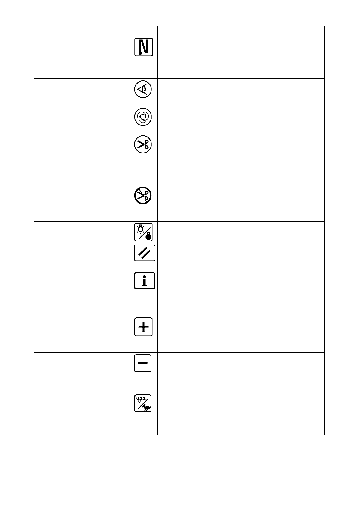
Switch Description
With/without reverse feed
stitch at sewing end switch
6
Edge sensor switch
7
One-shot automatic sewing
switch
8
With/without automatic
thread trimmer switch
9
Thread trimming prohibiting
switch
!0
Backlight switch
!1
This is the switch to turn ON/OFF automatic reverse feed
stitch at sewing end.
* This switch cannot be used with the sewing machine
which is not provided with automatic reverse feed stitching device.
Selects use/disuse of the material edge sensor in the case
the material edge sensor (edge) is installed on the sewing
machine.
When this switch is pressed, the sewing machine automati-
cally operates until the material edge sensor detects the
material edge or until the set number of stitches is reached.
This switch is used to automatically trim the thread when
the material edge sensor detects the material edge or until
the set number of stitches is reached.
* This switch cannot be used with the sewing machine
which is not provided with the automatic thread trimming
device.
This switch prohibits all thread trimmings.
* This switch cannot be used with the sewing machine
which is not provided with the automatic thread trimming
device.
This switch is used to change over the operation of the
backlight of the LCD between ON and OFF.
Reset switch
!2
Information switch
!3
Plus switch
!4
Minus switch
!5
Counter/speed changeover
!6
switch
General-purpose switch
!7
This is the switch to make the value of bobbin thread coun-
ter or sewing counter the set value. This switch is enabled
after thread trimming.
This switch is used to change over the screen between the
information function screen (sewing common data mode,
function setting mode, communication mode, version dis-
play, etc.) and the normal sewing screen.
This switch is enabled after thread trimming.
This switch is used to increase the set value of the bobbin
thread counter or the number of pcs. counter at the time of
setting. It should be remembered that this switch is enabled
after thread trimming.
This switch is used to decrease the set value of the bobbin
thread counter or the number of pcs. counter at the time of
setting. It should be remembered that this switch is enabled
after thread trimming.
This switch is used to change over the display between the
counter display and the maximum sewing speed limitation
display.
This switch has different functions depending on the
screen.
– 19 –
Page 23
– 20 –
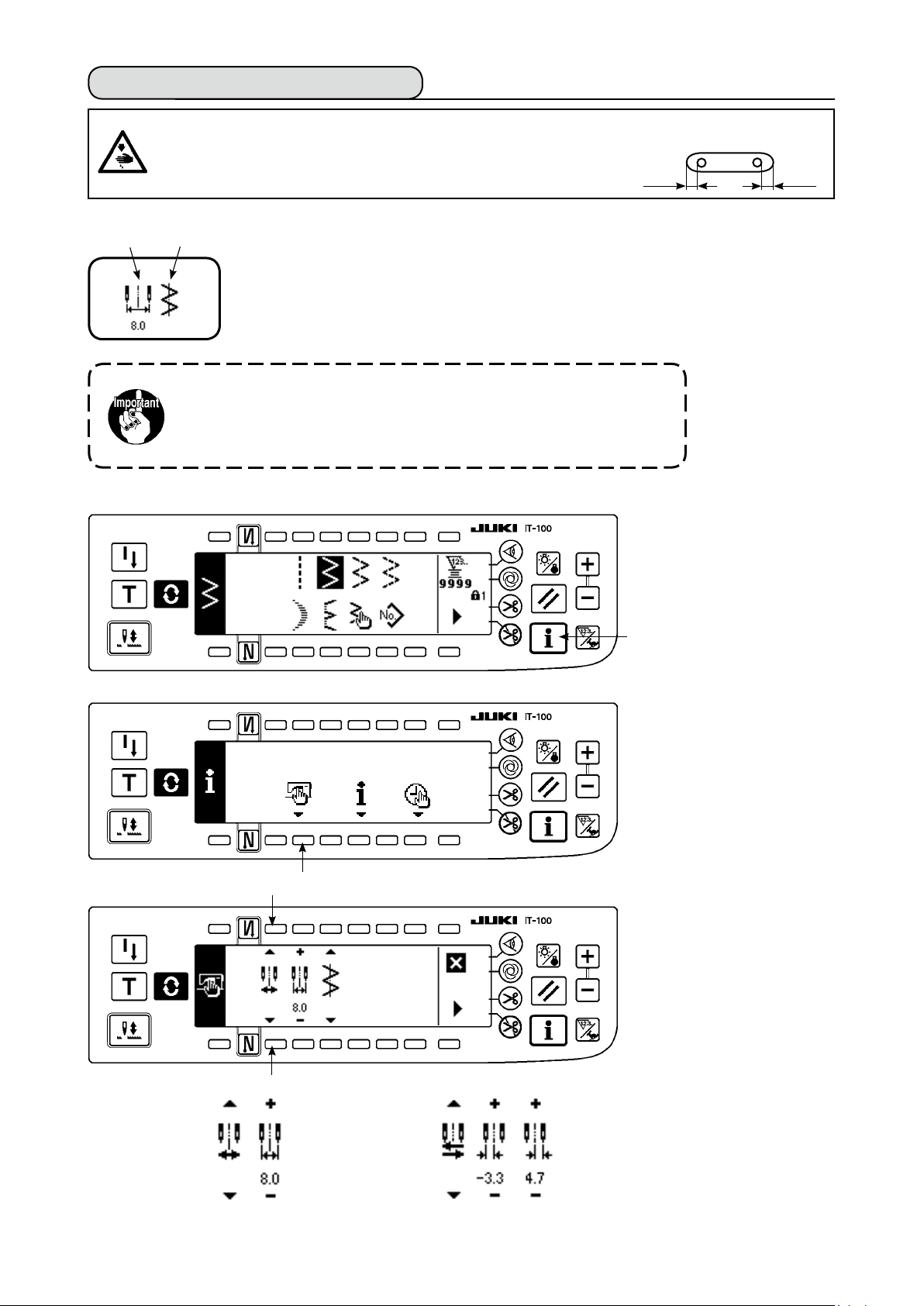
6-2. Before setting the pattern
WArNING :
Provide a clearance of 0.5 mm or more between the needle and the gauges when replacing the
gauges such as presser foot, throat plate, etc.
If the clearance is smaller than the specied value, it is in danger of
causing the needle to be broken or the like.
(1) Limitation of the max. zigzag width
q
Changeover of limiting procedure of max. zigzag width limitation value
■
w
• Max. zigzag width can be limited in accordance with the gauge.
• There are two kinds of limitations of max. zigzag width.
(1) Zigzag width symmetrical in the center
(2) Specifying left/right positions
Max. zigzag width limitation value and reference of stitch base line are displayed when
the power is turned ON.
Max. zigzag width limitation value (Screen changes in case of specifying left/right positions.)
1:
Reference of stitch base line
2:
Max. zigzag width limitation value and reference of stitch base line can be performed
with ON/OFF.
0.5
1) Press switch 1.
0.5
e
e
w
q
2) Press switch 2.
3) Figure on the left side is
the zigzag width symmet-
rical in the center mode.
Every time switch
pressed, specifying left/
right positions and zigzag
width symmetrical in the
center can be changed
over alternately.
3
is
⇔
(1) Zigzag width symmetrical in the center
(2) Specifying left/right positions
Page 24
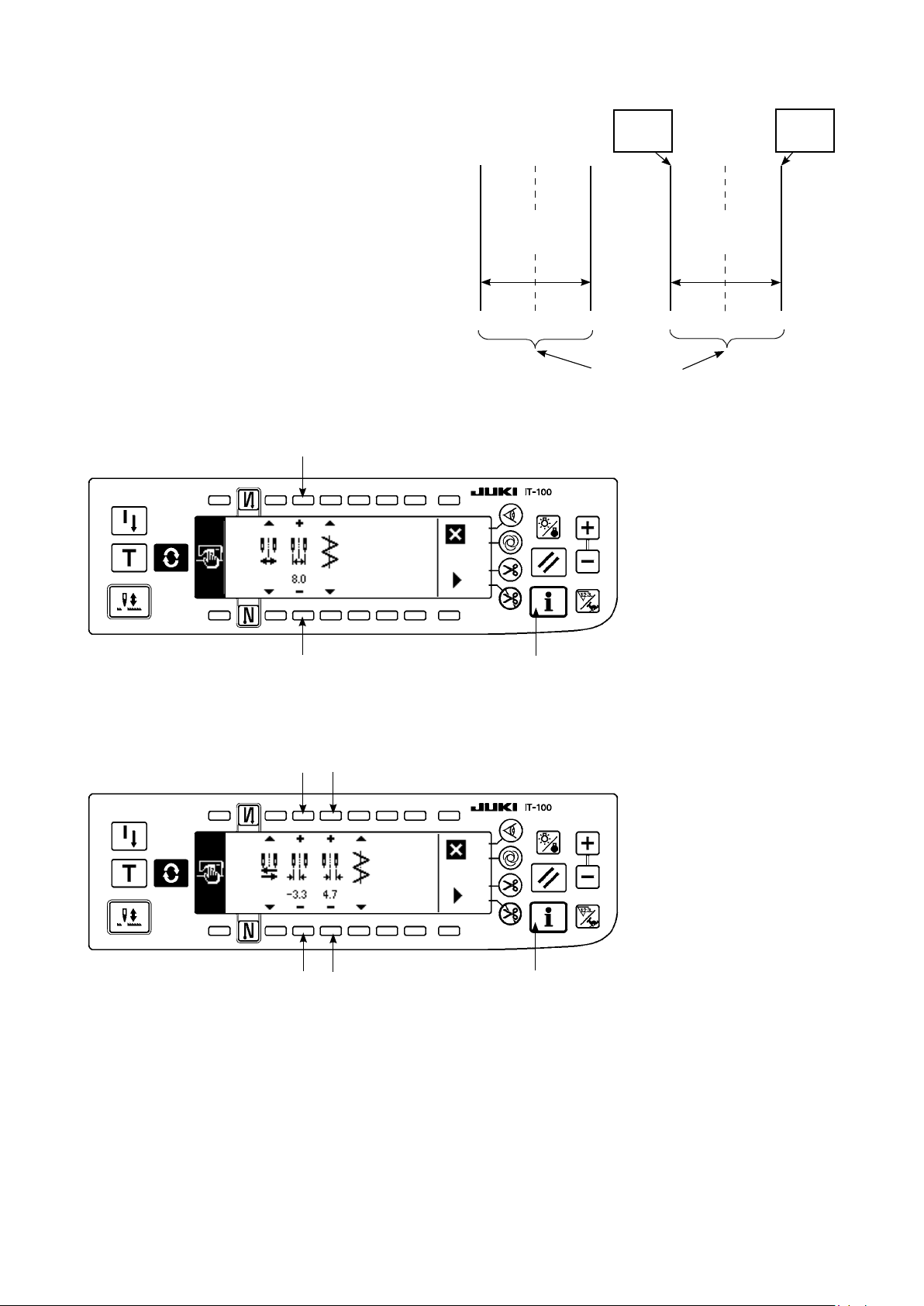
How to set max. zigzag width limitation value
■
Determine whether limitation of zigzag width symmet-
rical in the center or limitation of left/right positions
in the order of 1) to 3) of the previous page in accor-
dance with the gauge used.
Limitation of zigzag
width symmetrical
in the center
0.0 0.0
L = -3.3
Setting
Limitation of
left/right
positions
R = +4.7
Setting
–4.0 +4.0
(A) In case of zigzag width symmetrical in the center
4
4
Max. zigzag
width limitation
value
8.0
1
Max. zigzag
width limitation
value
8.0
–3.3 +4.7
Zigzag
limitation area
1) Press +/– of switch 4
and set the limitation
value.
In case of the example, set
the value to 8.0.
2) Press switch 1 and the
screen returns to the
previous one.
(B) In case of specifying left/right positions
6
5
6
5
1
Change of left side position limitation
1) Press +/– of switch
5
to
set the left side limitation
value.
In case of the example, set
the value to -3.3.
Change of right side position limitation
2) Press +/– of switch
6
to
set the right side limita-
tion value.
In case of the example, set
the value to +4.7.
3) Press switch 1 and the
screen returns to the
previous one.
– 21 –
Page 25
– 22 –
(2) Setting the reference of stitch base line
• Reference position of stitch base line can be set to left, center and right.
Reference of center
stitch base line
How to set
■
Reference of left
stitch base line
0.0 0.0 0.0
Reference of right
stitch base line
1) Press switch 1.
2
3
3
1
1
2) Press switch
2
.
3) Figure on the left side
shows the reference of
center stitch base line.
Every time switch 3 is
pressed, reference of left
stitch base line, that of right
stitch base line and that of
center stitch base line are
changed over and set alter-
nately.
Reference of left
stitch base line
Reference of center
stitch base line
Reference of right
stitch base line
4) Press switch 1 and the
screen returns to the
previous one.
Page 26
6-3. Basic screen
The screen after turning ON the power source becomes the screen at the time of turning OFF the power
source for the last time.
Every time
switch is pressed, the screen changes as follows :
Example) Free stitching of
on the set values.)
Sewing shape list rst screen
■
Selection of each shape is
performed.
* Free stitching means the
general sewing.
Sewing shape setting screen
■
Setting of zigzag width, position of stitch base line, etc. is performed.
2-step zigzag with reverse feed stitching (Contents of display change depending
Sewing shape list second screen
■
Press .
Press .
s
Press .
t
Press .
Reverse feed stitching setting screen
■
Setting of kind of condensation, number of stitches, etc. is performed.
Press .
When is pressed for approximately three seconds in a screen other than the sewing shape
list screen, the screen directly transits to the sewing shape list screen.
– 23 –
Page 27
– 24 –
6-4. List of the display pictographs of each screen
Sewing shape list rst screen
■
Straight stitch
Scallop Custom Pattern
Sewing shape list second screen
■
2-step zigzag stitch
Continuous stitching
Blind stitch
3-step zigzag stitch
4-step zigzag stitch
Cycle stitching
Scallop selection pop-up screen
■
Right standard Right crescent
Left equal 12 stitchesLeft equal 24 stitchesLeft standard Left crescent
Right equal 12 stitchesRight equal 24 stitches
Page 28
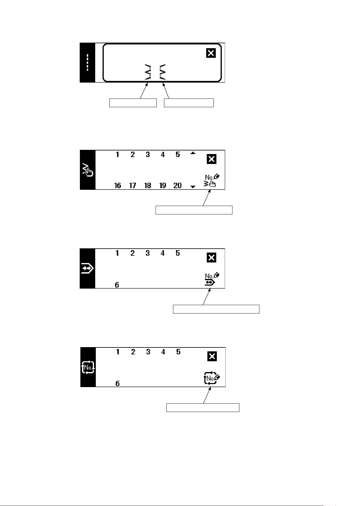
Blind stitch selection pop-up screen
■
Left blind stitch Right blind stitch
Custom pattern selection pop-up screen
■
Custom pattern new creation
Continuous stitching selection pop-up screen
■
Cycle stitching selection pop-up screen
■
Continuous stitching new creation
Cycle stitching new creation
The key lock level has been set to "1" at the time of delivery, and pictographs of new creation are not displayed. When performing new creation in each mode, change the key lock level to "0". (Refer to the second
screen of sewing common data setting of (1) Sewing common data of 6-15. Information. )
In addition, the display of pattern No. at the time of delivery is "1" only.
– 25 –
Page 29
– 26 –
Straight stitch sewing shape setting screen
■
Kind of
sewing
Free
stitching
Programmed
stitching
Overlapped
stitching
Position of
stitch base line
Pattern register
– 5.0
to
5.0
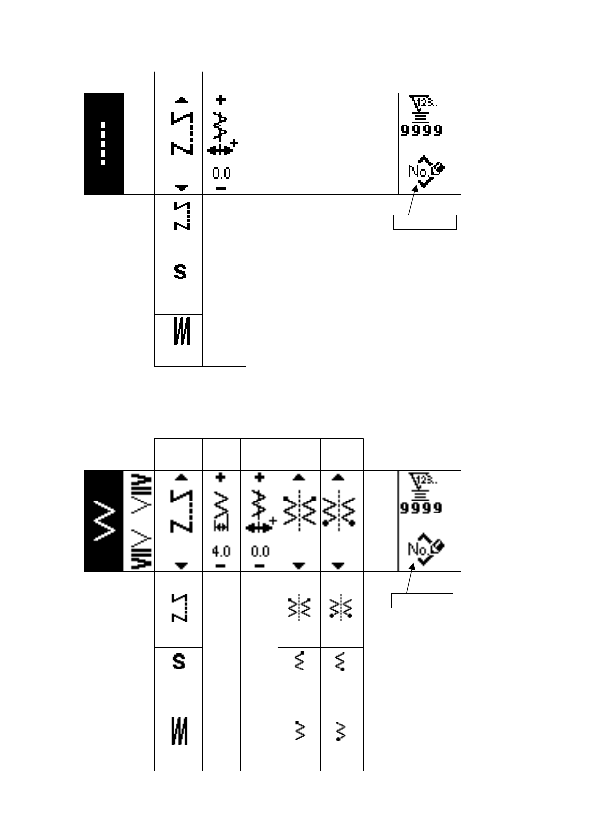
Sewing shape setting screen of 2-step zigzag stitch/3-step zigzag stitch/4-step zigzag stitch
■
Kind of
sewing
Free
stitching
Programmed
stitching
Zigzag
width
0
to
10.0
Position of
stitch base
line
– 5.0
to
5.0
Position
at sewing
start
Optional
Right
Position
at sewing
end
Pattern register
Optional
Right
Overlapped
stitching
Left
Left
Page 30
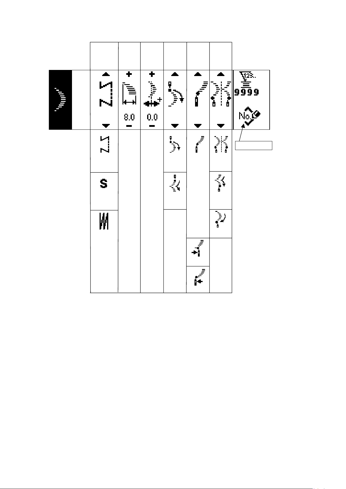
Scallop sewing shape setting screen
■
Kind of
sewing
Free
stitching
Programmed
stitching
Zigzag
width
0
to
10.0
Position of
stitch base
line
– 5.0
to
5.0
Position
at sewing
start
Root • Crest
Root
Crest
Position
at sewing
end
Root • Crest
Optional
Stop
position
Pattern register
Optional
Root
Overlapped
stitching
Right
Left
* Stop position is displayed when the position at sewing end is optional.
– 27 –
Page 31

– 28 –
Blind stitch sewing shape setting screen
■
Kind of
sewing
Free
stitching
Programmed
stitching
Overlapped
stitching
Zigzag
width
0
to
10.0
Position of
stitch base
line
– 5.0
to
5.0
Number
of stitches
Pattern register
3
to
250
Custom pattern sewing shape setting screen
■
Kind of
sewing
Free
stitching
Programmed
stitching
Zigzag
width
0
to
10.0
Position of
stitch base line
– 5.0
to
5.0
Custom pattern
needle entry image
Edit screen
display
Pattern register
Copy, and
deletion screen
Pattern register
Overlapped
stitching
Copy
Deletion
Page 32

Custom pattern edit screen
Needle entry
point insertion
■
Step Zigzag
position
input
1
to
500
– 5.0
to
5.0
Feed
direction
Normal •
Reverse
Normal
Reverse
Custom pattern
needle entry image
Needle entry
point insertion
Last needle entry input
Determination
Needle entry
point delection
Pattern sewing shape setting screen
■
Sewing
shape
Selection of
sewing shape
Straight stitch
2-step zigzag stitch
3-step zigzag stitch
4-step zigzag stitch
Scallop
(8 kinds)
Blind stitch
(Right and Left)
Custom
(1 to 20)
Kind of
sewing
Free
stitching
Overlapped
stitching
Display of contents depends on shape.
Refer to each shape.
Copy and
deletion screen
Copy
Deletion
– 29 –
Page 33

– 30 –
Continuous stitching setting screen
■
Zigzag
width
0.0
to
10.0
Position of
stitch base
line
–5.0
to
5.0
Step
1
to
20
Pattern
No.
Number
of stitches
Edit screen
display
Copy and
deletion screen
Copy
Deletion
Continuous stitching edit screen
■
Step
1
to
20
Pattern
No.
1
to
99
Sewing
shape
Number
of stitches
0
Determination
to
500
* For the sewing shape, the shape which has been registered in the pattern is displayed.
* Number of stitches cannot be set to "0". (Determination switch prohibition)
Page 34

Cycle stitching setting screen
■
Step
Pattern
No.
Number of
stitches
Stop
state
Position
of
presser
foot
Edit screen
display
* Stop state is not displayed when the number of stitches is
(0 stitch).
* Position of presser foot is displayed except the case where the
number of stitches is (0 stitch) with the auto-lifter.
* Presser lifting time is displayed when the position of presser foot is
UP stop.
Copy and
deletion screen
Copy
Deletion
Cycle stitching edit screen
■
Step
1
to
20
No.
Pattern
No.
1
to
99
Continuous
stitching
No.
1
to
20
Number of
stitches
(0 stitch)
to
500
Stop
state
Needle
DOWN
stop
Thread
trimming
Needle
UP stop
Position
of presser
foot
Presser
foot UP
stop
Presser
foot
DOWN
stop
Presser
lifting
time
Determination
0.1
to
99.9
* Stop state is not displayed when the number of stitches is (0 stitch).
* Position of presser foot is displayed except the case where the number of stitches is (0 stitch)
with the auto-lifter.
* Presser lifting time is displayed when the position of presser foot is UP stop.
– 31 –
Page 35

– 32 –
Reverse stitching setting rst screen
■
Reverse
stitching
at sewing
start With/
without
Reverse
stitching
at sewing
start With/
without
Sewing start
Selection
of kind
Normal 0 to 19
Process
A
Process
B
0 to 19
Sewing end
Selection
of kind
Normal 0 to 19
Process
C
Process
D
0 to 19
Custom
2-point
Reverse stitching setting second screen (2-point condensation)
■
Width
adjustment
at sewing
start
0 to 19
Width
0 to 19
adjustment
at sewing
-
end
Custom
2-point
0 to 19
0 to 19
0.0
to
– 5.0
0.0
to
– 5.0
Page 36

Reverse stitching setting second screen (Condensation custom)
■
0.0
to
Width
adjustment
at sewing
end
0.0
to
10.0
Width
adjustment
at sewing
start
10.0
Sewing common data setting rst screen (When max. zigzag width limitation is set in the
■
center)
Limiting
procedure
of max.zigzag
width limitation
Center
Max.zigzag
width
limitation
value
0.0
to
10.0
Reference
of stitch
base line
Center
Left
Right
Left/Right
When the limiting procedure of max. zigzag width limitation is set to “Left/Right”, the display of max.
*
zigzag width limitation value is separately indicated left and right.
– 33 –
Page 37

Sewing common data setting rst screen (When limiting procedure of max. zigzag width
■
limitation is set to left/right)
Limiting
procedure
of max.zigzag
width limitation
Left/Right
Specifying left
position
0.0
to
10.0
Specify
ing right
position
0.0
to
10.0
-
Reference
of stitch
base line
Center
Left
Right
Center
* When the limiting procedure of max. zigzag width limitation is set to “Center”, the display of max.
zigzag width limitation value becomes that of symmetrical in the center.
Sewing common data setting second screen
■
Mirror
function
setting
1 pattern
Condensation cus
tom stitch
base line
Interlocking
Counter
function
ON
Level 1
Key
lock
Max.zigzag
width limitation
when turning
ON the power
Display
Continuous
Fixed
OFF
OFF
Level 2
– 34 –
Nondisplay
Page 38

6-5. Setting the sewing pattern
WArNING :
Be sure to check presser foot and gauge currently being used before sewing after changing the
zigzag pattern or zigzag width. In case where sewing is performed with the presser foot or gauge not
matching the zigzag width, it is in danger of accident such as needle breakage or the like.
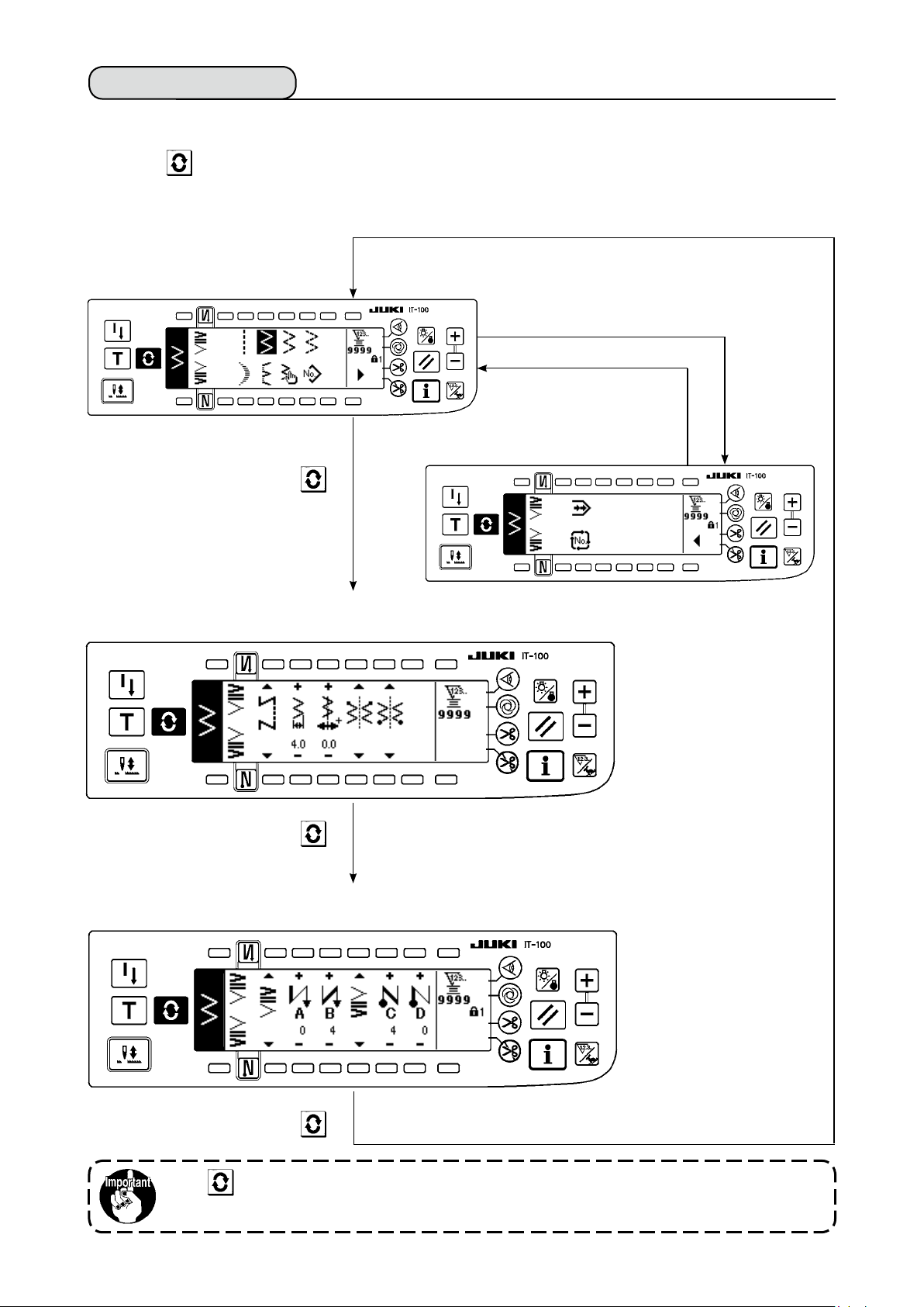
(1) Selecting the zigzag pattern
When▲ is pressed, the second screen is displayed.
:
1
When ▲is pressed, the rst screen is displayed.
:
2
Straight stitch
2-step zigzag
Determined pattern
First screen
■
3-step zigzag
4-step zigzag
A
Second screen
■
1
Pattern sewing
Custom pattern
Blind stitch
Scallop
Continuous stitching
2
Cycle stitching
1) Select the zigzag pattern you desire to sew with the selection switch when the gure above is in the
screen. The determined pattern is displayed in section A.
2) For scallop and blind stitch, select the shape with the next screen.
– 35 –
Page 39

– 36 –
Determined pattern
Left standard scallop
Left crescent scallop
Left equal-width scallop of 24 stitches
Left equal-width scallop of 12 stitches
In case of the scallop
1) Press the scallop key
and the screen on the
left side appears.
Press the pattern switch you
desire to select.
Right equal-width scallop of 12
Right equal-width scallop of 24
Right crescent scallop
Right standard scallop
2) As an example, press
the crescent scallop
key and the screen on
the left side appears
to determine the pat-
tern.
Determined pattern
In case of the blind stitch
1) Press the blind stitch
key and the screen on
the left side appears.
Press the pattern
switch you desire to
select.
Right blind stitch
Left blind stitch
2) As an example, press
the left blind stitch key
and the screen on the
left side appears to
determine the pattern.
Page 40

6-6. Setting of the sewing shape
• Zigzag width can be set from “0” to 10 mm. (Set value is limited by the max.zigzag width limitation.)
• Stitch base line can be set as follows. When the center of zigzag is “0.0”, Right side : “+” Left side : “–”.
(1) 2-step zigzag, 3-step zigzag and 4-step zigzag stitch
Sewing shape list rst screen
■
2-step zigzag
1) Select 2-step (3-step or 4-step) zigzag stitch in the sewing shape list rst screen.
2) The selected shape reverses and is displayed on the left end of the screen.
3) Press to display the sewing shape setting screen.
Sewing shape setting screen
■
3-step zigzag
4-step zigzag
4455667
7
Setting of the zigzag
width
Change the zigzag width
with +/– of switch
Setting of the position
of stitch base line
Change the position of
stitch base line with +/– of
switch
5
.
4
.
Setting of the position of sewing start
Set the position of sewing start with
▲/▼
of switch
Sewing start Optional Sewing start Right Sewing start, left
Setting of the stop position
Set the stop position with
▲/▼
of switch
7
.
Stop position, optional Stop position, right Stop position, left
– 37 –
6
.
Page 41

– 38 –
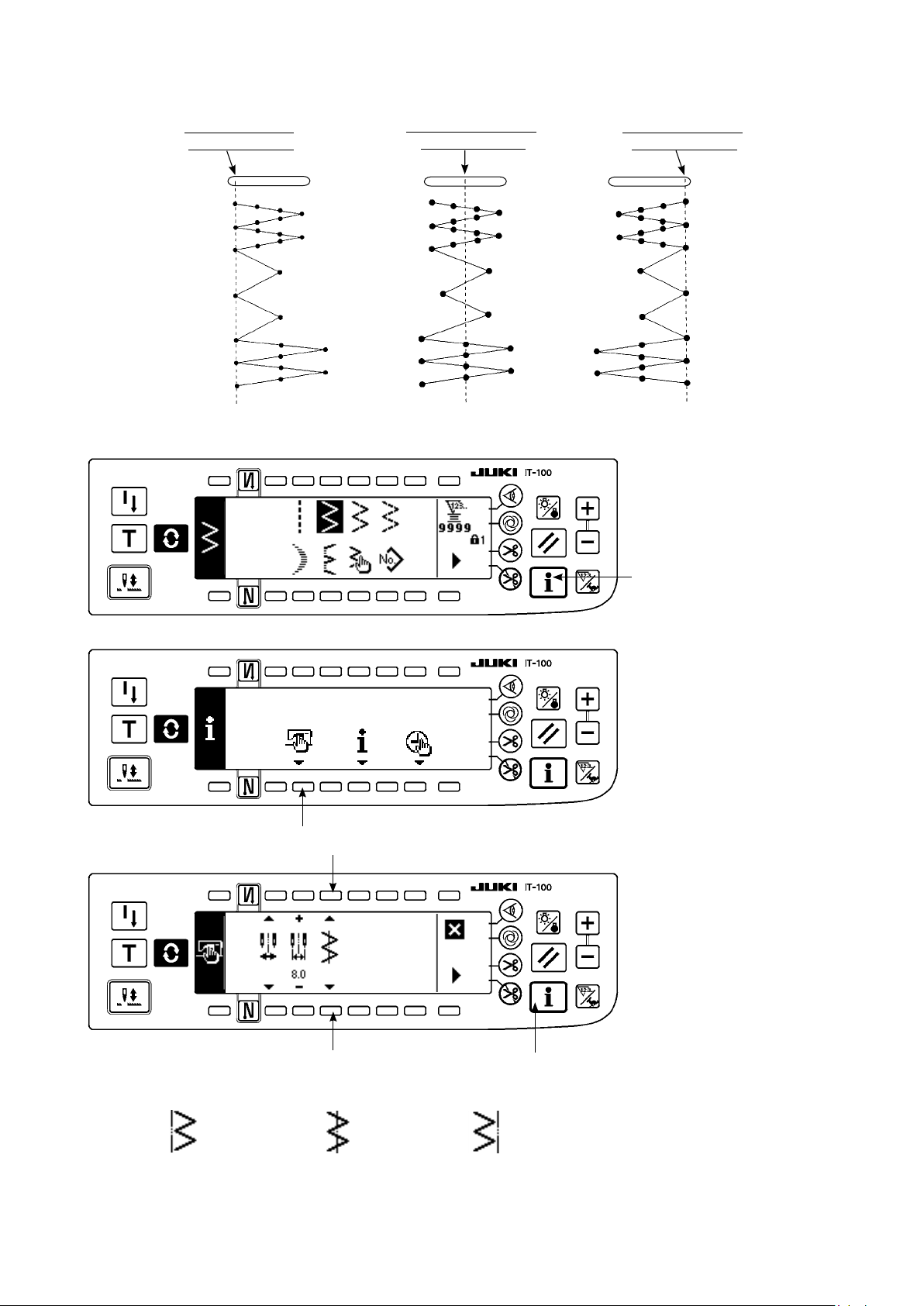
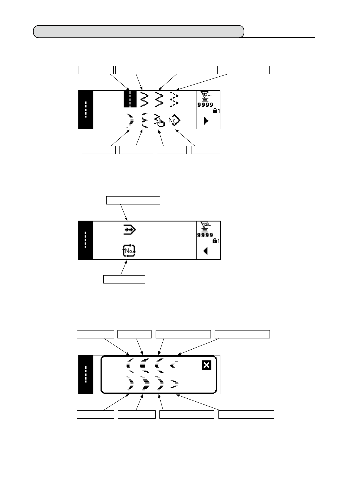
(2) Scallop stitching
Sewing shape list rst screen
■
1
Scallop selection pop-up screen
■
h
1) Select scallop stitch-
in the sewing
ing
1
shape list rst screen.
Left standard
scallop
Right standard
scallop
Sewing shape list rst screen
■
Left crescent
scallop
Right crescent
scallop
Left equalwidth scallop of
24 stitches
Right equalwidth scallop of
24 stitches
h
Left equalwidth scallop of
12 stitches
2) Press the switch of
pattern to be selected
from the screen of the
left gure.
Right equalwidth scallop of
12 stitches
3) The selected shape
reverses and is indi-
cated on the left end
of the screen.
Sewing shape setting screen
■
q w e r t
q w e r t
4) Press to display
the sewing shape set-
ting screen.
Setting of the zigzag
width
Change the zigzag width
with +/– of switch 1.
Setting of the position
of stitch base line
Change the position of
stitch base line with +/–
of switch 2.
Page 42

Setting of the position of sewing start
Set the position of sewing start with
Sewing start, root Sewing start, crest
Start from crest and start from root of scallop
●
Start of sewing
Start from root
Needle position
after thread
trimming
Start from crest
▲ / ▼
of switch
.
3
Normally, scallop starts
the sewing with the pattern of start from root.
However, start from crest
can be selected by changing the setting.
Setting of the stop position right/left
Set the stop position with
Stop position, optional Stop position, right Stop position, left
Setting of the stop position
Set the stop position with
▲ / ▼
▲ / ▼
of switch
of switch
4
5
.
.
Stop position, optional Stop position, root
– 39 –
Page 43

– 40 –
(3) Blind stitch sewing
Sewing shape list rst screen
■
1
h
Blind stitch selection pop-up screen
■
1) Select the blind stitch
sewing in the sewing
shape list rst screen.
2) Press the switch of
pattern to be selected
from the screen of the
left gure.
Left blind stitch
Sewing shape rst screen
■
Sewing shape setting screen
■
h
q w e
w eq
Right blind stitch
3) The selected shape
1
-
.
reverses and is indi
cated on the left end
of the screen.
4) Press to display
the sewing shape set-
ting screen.
Setting of the zigzag
width
Change the zigzag width
with +/– of switch
Setting of the position
of stitch base line
Change the position of
stitch base line with +/– of
switch
Change of the number
of stitches
Change the number of
stitches with switch 3.
2
.
Page 44

(4) Custom pattern stitching
Sewing shape list rst screen
■
1
h
Custom pattern selection pop-up screen
■
1) Select custom pattern
in the sewing shape
1
list rst screen.
Sewing shape list rst screen
■
Sewing shape setting screen
■
h
2) Press the custom pat
tern No. to be select-
ed.
3) The selected shape
reverses and is indi-
cated on the left end
of the screen.
4) Press to display
the sewing shape set-
ting screen.
-
q w
wq
– 41 –
Setting of the zigzag
width
Change the zigzag width
with +/– of switch
Setting of the position
of stitch base line
Change the position of
stitch base line with +/– of
switch
2
.
1
.
Page 45

– 42 –
6-7. Reverse feed stitching
1
OFF ON ON
A
B
Sewing
pattern
OFF OFF
2
Reverse feed stitching setting screen
■
OFF
C
D
ON ON
q
Reverse feed stitching can be set with each zigzag pat-
tern.
A
Effective/ineffective of reverse feed stitching can be set
by pressing reverse feed stitch at sewing start switch
B
and reverse feed stitch at sewing end switch
1
2
. In
case the reverse feed stitching is effective, the respec-
tive shapes of the reverse feed stitching are displayed. In
case of ineffective, the shape is not displayed.
C
D
w
For the reverse feed stitching, there are standard condensation, 2-point condensation and condensation
custom.
Page 46

(1) Standard condensation
Standard condensation performs reverse feed stitching at the same needle entry as that of the selected
zigzag pattern.
Example) Reverse feed stitching at sewing end
Zigzag pattern section
3-step zigzag stitching
Standard condensation section
Process C : 4-times setting
Example) In case of free stitching of the 2-step zigzag stitch
1) Press to display reverse feed stitching setting screen.
2) Set the shape of condensation and number of stitches.
: Select the shape of condensation at the sewing start.
1
: Set the number of stitches of process A with “+” and “–”.
2
: Set the number of stitches of process B with “+” and “–”.
3
: Select the shape of condensation at the sewing end.
4
: Set the number of stitches of process C with “+” and “–”.
5
: Set the number of stitches of process D with “+” and “–”.
6
Display section of
and 4 : Standard condensation, 2-point condensation and condensation custom (20
1
patterns) are changed over and displayed.
Reverse feed stitching setting (standard condensation) screen
■
qqwweerrtty
y
– 43 –
Page 47

– 44 –
* For the reverse feed stitching setting, there are two kinds of methods below according to the zigzag patterns.
1) In case of straight stitch, scallop stitch, blind stitch, custom and continuous stitch, set the reverse feed
stitching with the number of stitches.
Reverse feed stitching at sewing start
B (feed in reverse direction) : 0 to 19 stitches can be set.
Reverse feed stitching at sewing end
D (feed in normal direction) : 0 to 19 stitches can be set.
A (feed in normal direction) : 0 to 19 stitches can be set.
→
C (feed in reverse direction): 0 to 19 stitches can be set.
→
……
……
……
……
2
3
5
6
* The pictures in case of straight stitching are
sewing start and 4 sewing end .
1
2) In case of 2-step zigzag, 3-step zigzag and 4-step zigzag, set the reverse feed stitching with the number of
times of zigzag pattern. Zigzag pattern means the space between the returning points of zigzag.
Reverse feed stitching at sewing start
B (feed in reverse direction) : 0 to 19 times can be set.
Reverse feed stitching at sewing end
D (feed in normal direction) : 0 to 19 times can be set.
1 time
2 time
2-step zigzag stitch 3-step zigzag stitch 4-step zigzag stitch
A (feed in normal direction) : 0 to 19 times can be set.
→
C (feed in reverse direction): 0 to 19 times can be set.
→
1 time
2 time
1 time
2 time
………
………
………
………
2
3
5
6
(2) 2-point condensation
2-point condensation performs reverse feed stitching of two points between the existing needle entry of the
selected zigzag pattern and the next needle entry.
The width between two points can be adjusted in the direction of “–”.
Example) Reverse feed stitching at sewing end
Zigzag pattern section
3-step zigzag stitch
2-point condensation section
Process C : 4 stitches setting
Compensation can be performed in the direction of “–”. (In case of the
gure, the width narrows to the left side.)
Example) In case of free stitching of the standard zigzag stitch
1) Press to display reverse feed stitching setting screen.
2) Set the shape of condensation and number of stitches with the rst screen.
: Select the shape of condensation at the sewing start.
1
: Set the number of stitches of process A with “+” and “–”. 0 to 19 stitches can be set.
2
: Set the number of stitches of process B with “+” and “–”. 0 to 19 stitches can be set.
3
: Select the shape of condensation at the sewing end.
4
: Set the number of stitches of process C with “+” and “–”. 0 to 19 stitches can be set.
5
: Set the number of stitches of process D with “+” and “–”. 0 to 19 stitches can be set.
6
Display section of 1 and 4 : Standard condensation, 2-point condensation and condensation custom
(20 patterns) are changed over and displayed.
Page 48

3) Set 2-point condensation width adjustment with the second screen. (Width can be narrowed up to max. –
5 mm.)
: Set 2-point condensation width adjustment at the sewing start.
7
: Set 2-point condensation width adjustment at the sewing end.
8
* 2-point condensation width adjustment can narrow the width from the rst needle entry position to the next
needle entry position when performing the reverse feed stitching. (When set value is “0”, there is no com
pensation.)
* When the width adjustment is performed, the width between 2 points can be narrowed and the fray of
thread is lessened.
The rst screen of reverse feed stitching setting (2-point condensation)
■
q w e r t y
-
q w e r t y
▲
Press to display the second screen.
The second screen of reverse feed stitching setting (2-point condensation)
■
u i
u i
Press to display the rst screen.
▲
– 45 –
Page 49

– 46 –
(3) Condensation custom
Condensation custom performs reverse feed stitching with the optional needle entry which has been input-
ted.
1) Select the shape of condensation with the rst screen.
2) Set the width of condensation custom pattern with the second screen.
* Separately set inputted zigzag width of condensation custom from that of normal sewing section. Set the
width within the range of maximum zigzag width limitation.
* By setting the width, the needle entry differs from actually inputted needle entry position.
The rst screen of reverse feed stitching setting (condensation custom)
■
: Select the shape of condensation at the sewing start.
1
: Select the shape of condensation at the sewing end.
3
: Needle entry position is displayed.
2, 4
: Set the width of condensation custom pattern at the sewing start.
5
: Set the width of condensation custom pattern at the sewing end.
6
q w e
4
q e
Press to move the screen to the edit screen.
* For the editing procedure, refer to "6-10. Condensation custom".
▲
Press to display the second screen.
The second screen of reverse feed stitching setting (condensation custom)
■
t y
t y
Press to display the rst screen.
▲
Page 50

(4) Comparison table of the reverse stitch of each shape
Straight stitch
2-step zigzag
stitch
3-step zigzag
stitch
4-step zigzag
stitch
Standard condensation
Sewing start Sewing end
2-point condensation
Sewing start Sewing end
Condensation custom
Sewing start Sewing end
Scallop
Blind stitch
Custom
Continuous stitch
– 47 –
Page 51

– 48 –
6-8. Selection of the kind of stitching
Standard delivery level of the key lock is “1”. When the level of the key lock is the case
other than “0”, be sure to change the level to “0” to perform the operation below.
Example) 2-step zigzag
Sewing shape setting screen
■
q
Select the kind of stitching
q
(1) Overlapped stitching
Overlapped stitching setting screen
■
w e r t
w e r t
1) Select showing overlapped stitching with
of sewing shape setting screen.
1
from among free stitching
overlapped stitching
programmed stitching
Press switch
shape setting screen to se
lect the kind.
of sewing
1
and
,
.
-
2) Press
3) Set the number of stitches and number of processes of the respective processes in the overlapped stitching setting screen
: Set the number of stitches of process A with “+” and “–”. 0 to 19 stitches for the number of stitches of
2
: Set the number of stitches of process B with “+” and “–”. 0 to 19 stitches for the number of stitches of
3
: Set the number of stitches of process C with “+” and “–”. 0 to 19 stitches for the number of stitches of
4
: Set the number of processes with “+” and “–”. 0 to 9 times for the number of processes can be set.
5
4) By performing depressing the front part of the pedal, the sewing machine repeats the specied number of
times of normal and reverse feed stitching, performs automatic thread trimming and stops.
* Turn ON the thread trimming prohibition switch ON when you desire to stop the sewing machine with
needle UP position without performing thread trimming after all processes have been completed.
* Thread trimming is performed at any occasion in case of one-shot stitching and the last of process. The
one-shot stitching cannot be turned OFF.
to display overlapped stitching setting screen.
section A can be set.
section B can be set.
section C can be set.
(2) Programmed stitching
Programmed stitching
■
Programmed stitching can program the constant-dimension stitching process up to 20 steps and set the
number of stitches to each step up to 500 stitches.
* For the programmed stitching, the pattern registration cannot be performed.
Page 52

Example) 2-step zigzag
Sewing shape setting screen
■
q
q
Programmed stitching selection screen
■
w
w
Press ▲, in case of more than 10 steps, and programmed stitching
selection screen of “11” to “20” is displayed.
Press ▲ and the screen returns to programmed stitching selection screen
of “01” to “10”.
1) Select
grammed stitching with 1
of sewing shape setting
screen.
2) Press
programmed stitching set
ting screen.
3) Number of stitches of
each step is displayed in
the programmed stitching
setting screen.
Press switch
sponding to each step
and the screen moves to
the programmed stitching
edit screen.
showing pro-
to display the
corre-
2
-
When automatic thread trimming is selected, “0” is not displayed in the last step.
When increasing the number of steps, proceed to the next step after releasing
automatic thread trimming.
Programmed stitching edit screen
■
e r
e r
4) Set the number of stitches of each step in the programmed stitching edit screen.
: Set the step with “+” and “–”. As many as 20 steps can be set.
3
: Set the number of stitches with “+” and “–”. As many as 500 stitches can be set.
4
5) When setting of all steps has been completed, select automatic thread trimming
stitch to the next step.
When the last step is “20”, it is not necessary to set “0” stitch at the next step.
6) When setting is completed, press key to determine the contents of setting.
t
y
at the last step, or set “0”
6
When the power source is turned OFF without pressing key, the inputted data returns
to the former one. When you desire to determine the data, be sure to press key.
– 49 –
Page 53

– 50 –
One-shot automatic stitching
■
One-shot automatic stitching can be set by each step.
1) In the programmed stitching edit screen, press one-shot automatic stitching switch 5 to select the one-
shot automatic stitching. (When it is in the selected state, a mark is displayed on the side of switch 5.)
2) In the step where the one-shot automatic stitching has been selected, the sewing machine will automati-
cally continue sewing, once the sewing machine starts running, until the number of stitches of the step is
reached.
Teaching
■
Teaching can input the number of stitches of inputting step with the number of stitches which has been actu-
ally sewn.
1) Press
2) Depress the front part of the pedal to sew until the last stitch of the step is reached.
* At this time, input of number of stitches cannot be performed by turning handwheel by hand or using
needle up/down compensating switch.
3) Stop the sewing machine with the pedal in the neutral position and the number of stitches which has been
sewn is displayed on
4) Make the step of 1 proceed to the subsequent step or make the sewing machine perform thread trim-
ming. Then the input of the number of stitches for the step is completed.
Teaching screen
■
switch in the programmed stitching edit screen and the teaching mode is selected.
.
2
: Set the step with "+".
1
: Number of stitches which has been sewn can be corrected by hand with “+” and “–”.
2
q w
w
6-9. Custom pattern
Standard delivery level of the key lock is “1”. When the level of the key lock is the case other
than “0”, be sure to change the level to “0” to perform the operation below.
Free needle entry position can be specied and optional zigzag pattern can be created.
As many as 20 patterns can be created and as many as 500 stitches of each pattern can be inputted.
(1) Custom pattern setting
Sewing shape list screen
■
1) Press switch 1 of
in the sewing shape list
screen.
q
Page 54

Custom pattern selection pop-up screen
■
w
Sewing shape setting screen
■
2)
Press switch
ing to the pattern which
has been registered in the
custom pattern selection
pop-up screen.
2
correspond-
e r t
6
e r t
3) Press to display the sewing shape setting screen.
4) Zigzag width, position of stitch base line, etc. of custom pattern can be set in the sewing shape setting
screen.
: Select free stitching, overlapped stitching or programmed stitching.
3
: Set the zigzag width with “+” and “–”. (The whole can be enlarged or reduced taking the inputted left
4
and right positions as reference.)
: Set the position of stitch base line with “+” and “–”.
5
: Needle entry position is displayed.
6
(2) New creation of the custom pattern
Custom pattern is newly created.
New creation pop-up screen
■
q
q
1) Press in the custom pattern selection pop-up screen to display the new creation pop-up screen.
2) Nos. which have not been registered at present are displayed in
tain with “+” and “–”.
When is pressed here, the screen returns to the former one without creating the pattern.
3) When
The No. which has been created is in the selective state. Continue to perform the edit of custom pat
tern.
is pressed, new creation is performed.
– 51 –
. Select the No. you desire to ob-
1
-
Page 55

– 52 –
(3) Custom pattern edit
1) Press switch of in the sewing shape setting screen to move to the custom pattern edit screen.
Custom pattern edit screen
■
u i o
!0
!3
u i
2) Set the needle entry position and sewing direction of each step in the custom pattern edit screen.
: Set the step with
7
: Set the value of needle entry point from the center of zigzag with
8
right side and
: Select normal direction and reverse direction with the feed direction.
9
: Needle entry position is displayed. (In display of the needle entry position, all positions are displayed
!0
as the normal direction.)
: Insert needle entry point 0.0 for one stitch to the existing step. Then the stitches move backward one
!1
stitch by one stitch.
* It is not possible to insert it when the number of total stitches is 500 stitches.
: Delete one stitch of the needle entry of the existing step. Then the stitches move forward one stitch
!2
by one stitch.
* It is not possible to delete it when the number of total stitches is
3) When setting is completed up to the last step, proceed to the next step, press !3 and put END mark .
* When the number of stitches of the last step is 500 stitches, it is not necessary to set “END” mark .
4) When the setting is completed, press key to determine.
When the power source is turned OFF without pressing key, the inputted data returns to
the former one. When you desire to determine the data, be sure to press key.
“+” and “–”
“–”
value on the left side.
o
!1
.
!2
“+”
“1”
and
stitch.
“–”. “+”
value comes on the
When the setting of reverse direction is performed in the setting of the feed direction of the
custom pattern, the max. speed is limited to 1,100 sti/min.
(4) Registration, copy and deletion of the custom pattern
Pop-up screen of registration, copy and deletion of custom pattern
■
q w e
Press in the sewing shape setting screen, and the pop-up screen of registration, copy and deletion of
custom pattern appears. Then registration, copy and deletion of the custom pattern can be performed.
Page 56

Registration of pattern
○
Registration pop-up screen
■
r
r
1) Press
2) Select the pattern No. you desire to register with 4 in the registration pop-up screen.
When
3) When
After registration, the registered pattern is in the selective state.
○
How to copy
Copy pop-up screen
■
in the pop-up screen of registration, copy and deletion of custom pattern.
1
is pressed here, the screen returns to the former one without registering the pattern.
is pressed, registration is performed.
t y
t y
1) Press
2) Copy pop-up screen is displayed.
: Select the custom pattern of copy source with “+” and “–”. (It is possible to select only No. which has
5
been registered.)
: Select the custom pattern of copy destination with “+” and “–”. (It is possible to select only No. which
6
has been not registered.)
When
3) When is pressed, copying is performed.
When copying is performed, the No. which is selected as copy destination is in the selective state.
○
How to delete
Deletion pop-up screen
■
in the pop-up screen of registration, copy and deletion of custom pattern.
2
is pressed here, the screen returns to the former one without performing copy.
u
u
– 53 –
Page 57

– 54 –
1) Press 3 in the copy pop-up screen and the deletion pop-up screen to display the deletion pop-up
screen.
2) Select the pattern No. you desire to delete in the deletion pop-up screen.
: Select the pattern to be deleted with “+” and “–”.
7
When is pressed here, the screen returns to the former one without deleting.
3) When
is pressed, deletion is performed.
Once the data is deleted, it does not return to the former one. Be sure to press after
carefully checking the data.
When the number of registered pieces is one, deletion cannot be performed. When you
desire to delete it, perform deletion after creating another No.
The custom pattern registered in the pattern cannot be deleted.
6-10. Condensation Custom
Standard delivery level of the key lock is “1”. When the level of the key lock is the case
other than “0”, be sure to change the level to “0” to perform the operation below.
Condensation custom can perform condensation by specifying free needle entry position.
Condensation custom patterns can be created up to as many as 64 steps. As many as 20 patterns can be
registered at the sewing start and the sewing end respectively.
(1) Condensation custom setting
Reverse feed stitching setting (condensation custom) screen
■
q e
w
4
eq
1) Press to display the reverse feed stitching setting screen.
2) Select the shape of condensation in the reverse feed stitching screen.
: Select the shape of condensation at sewing start from among 1 to 20.
1
Standard condensation , 2-point-condensation and condensation customs to are
changed over and displayed in the display section.
: Select the shape of condensation at sewing end from among 1 to 20.
3
Standard condensation , 2-point condensation and condensation customs to are
changed over and displayed in the display section.
and
2
: Needle entry position is displayed when selecting the condensation custom.
4
Page 58

(2) Condensation custom edit
Condensation custom edit screen
■
q w
e
y
q w
1) Press to display the reverse feed stitching setting screen.
2) Press
screen.
3) Set the needle entry position for each step in the condensation custom edit screen.
: Set the step with “+” and “–” key.
1
: Set the value of needle entry point from the center of zigzag with “+” and “–”. “+” value comes on the
2
: Needle entry position is displayed.
3
: Insert needle entry point 0. 0 for one stitch to the existing step. Then the stitches move backward
4
* It is not possible to insert it when the number of total stitches is 64 stitches.
: Delete one stitch of the needle entry of the existing step. Then the stitches move forward one stitch
5
* It is not possible to delete it when the number of total stitches is “1” stitch.
4) When setting up to the last step is completed, proceed to the next step, press
mark .
* When the last step is 64, it is not necessary to set "END" mark .
5) When all inputting procedures have been completed, press
or 4 in the reverse feed stitching setting screen to move to the condensation custom edit
2
right side and “–” value on the left side.
one stitch by one stitch.
by one stitch.
r t
6 and put END
key to determine.
The second screen of reverse feed stitching setting
■
q
Example) Condensation custom at sewing start Width 4 mm for 2-step zigzag stitch
Needle
entry
Input
value
Input the data of the list in the condensation custom edit screen.
1
Set 4 mm at 1 in the 2nd screen of reverse feed stitching setting. When 1 is changed, the inputted
2
needle entry can be increased/decreased.
1st
stitch
– 2.0 – 0.7 0.6 2.0 0.6 – 0.7 – 2.0 – 0.7 0.6
2nd
stitch
3rd
stitch
4th
stitch
5th
stitch
6th
stitch
7th
stitch
8th
stitch
9th
stitch
10th
stitch
2.0 END
11th
stitch
– 55 –
Page 59

– 56 –
When the power source is turned OFF without pressing key, the inputted data returns
to the former one. When you desire to determine the data, be sure to press key.
Feed direction of all of the condensation custom patterns is in the reverse feed direction.
6-11. Pattern stitching
Standard delivery level of the key lock is “1”. When the level of the key lock is the case other
than “0”, be sure to change the level to “0” to perform the operation below.
The respective shapes of straight stitch, 2-step zigzag, 3-step zigzag, 4-step zigzag, scallop, blind stitch, and
custom can be registered in the pattern.
Patterns, the zigzag width of which is different from each other, and those, the positions of the stitch base
line of which are different from each other can be changed over and used without re-setting the data even in
case of the same zigzag shape by registering as patterns.
It is possible to register as many as 99 patterns.
(1) Setting the pattern stitching
Example) Scallop stitching
The second screen of the sewing shape list
■
q
Pattern selection pop-up screen
■
w
1) Select 1 in the
second screen of the
sewing shape list.
2) Press switch
sponding to the sew-
ing which has been
registered, or the pat-
tern you desire to edit
in the pattern selec-
tion pop-up screen.
corre-
2
3) Press to display
the sewing shape set-
ting screen.
Page 60

Sewing shape setting screen
■
q
e
* When there is the second
screen,
-
○
○
○
○
w e
Position of
stitch base line
○
○
○
○
○
r
t
Position at
sewing start
-
○
○
-
-
Stop position
-
○
○
-
-
“+” and “–”.
q
4) Setting of the respective items can be performed in the sewing shape setting screen.
Shape
Straight
2-step
zigzag
3-step zigzag
4-step zigzag
Scallop
Zigzag width
Blind stitch
Custom
: Pattern No. which has been registered can be selected with
1
: Select the pattern shape. Sewing shape can be changed by the pattern No. which is being selected at
2
present.
▲
is displayed.
4
Number of stitches of
blind stitch
-
-
-
○
-
When the sewing shape is changed, the respective setting data return to the initial values.
: Select the kind of stitching. Free stitching and overlapped stitching can be selected.
3
(2) Registering the pattern stitching
It is possible to register at the time of free stitching and overlapped stitching.
Select in advance the shape you desire to register from the sewing shape list screen.
Example) Scallop stitching
Sewing shape setting screen
■
1) Press
sewing shape setting
screen.
2) Press 1 to display
the new registration pop-
up screen in the sewing
shape setting screen.
q
to display the
– 57 –
Page 61

– 58 –
New registration pop-up screen
■
w
3) Select the pattern No.
to which you desire to
register with
registration pop-up screen.
When is pressed here,
the screen returns to the
former one without perform-
ing the registration.
in the new
2
w
4) When is pressed,
registration is performed.
The registered pattern is
in the selective state after
registration has been
performed.
(3) Copy and deletion of the pattern stitching
Press 5 in the sewing shape setting screen to display the copy and deletion pop-up screen. Then copy
and deletion of the pattern stitching can be performed.
How to copy
○
Copy and deletion pop-up screen
■
Copy pop-up screen
■
e r
1) Press 1 in the
copy and deletion pop-up
screen to display the copy
pop-up screen.
q w
2) Set the pattern Nos. of
the copy source and copy
destination in the copy
pop-up screen.
e r
: Select pattern No. of the copy source with “+” and “–”. (Registered Nos. only can be selected.)
3
:
4
When is pressed here, the screen returns to the former one without performing copy.
3) When
No. of the copy destination is in the selective state after copy has been performed.
Select pattern No. of the copy destination with “+” and “–”. (Non-registered Nos. only can be se-
lected.)
is pressed, copy is performed.
Page 62

How to delete
○
Deletion pop-up screen
■
t
t
When is pressed here, the screen returns to the former one.
1) Press
copy and deletion pop-
up screen to display the
deletion pop-up screen.
2) Select pattern No. you
desire to delete in the
deletion pop-up screen.
: Select the pattern to
5
be deleted with “+” and
“–”.
2
in the
3) When
is pressed, deletion is performed.
Once the deletion is performed, the data is not restored.
Be sure to carefully check before pressing
When the number of registered pieces is one, deletion cannot be performed. When you desire
to delete it, perform deletion after creating another No.
The pattern used in continuous stitching or cycle stitching cannot be deleted.
.
6-12. Continuous stitching
Standard delivery level of the key lock is “1”. When the level of the key lock is the case other
than “0”, be sure to change the level to “0” to perform the operation below.
The continuous stitching is a function created by supposing the case where the different patterns are connected and sewn, or the case where the sewing is performed beyond max. number of stitches per pattern,
500 stitches. Therefore, the connected patterns are recognized as one pattern.
Continuous stitching can sew the different zigzag patterns in combination.
Changeover of the respective patterns can be set with the number of stitches.
Continuous stitching can combine as many as 20 steps and 500 stitches per step can be set. In addition, up
to 10 patterns can be registered.
To perform the continuous stitching, it is necessary to register in advance the pattern to be used in each step.
3-step zigzag stitch
Number of stitches :
4 stitches
2-step zigzag
stitch Number of
stitches : 4 stitches
4-step zigzag stitch
Number of stitches :
4 stitches
– 59 –
Example) When you desire to create the needle
entry positions as shown in the gure
below.
1) Register in advance 2-step zigzag stitch at pat
tern 1, 3-step zigzag stitch at pattern 2, and
4-step zigzag stitch at pattern 3.
2) Set the number of stitches as shown in the table
below.
No. of step
1
2
3
3) When “END” mark is set to the 4th step, reg-
istration has been completed.
Pattern No.
2
1
3
Number of stitches
-
4
4
4
Page 63

– 60 –
(1) New creation of the continuous stitching
Continuous stitching pattern can be newly created.
New creation pop-up screen
■
1) Press in the continuous stitching selection pop-up screen to display the new creation pop-up screen.
q
q
2) Nos. which have not been registered at present are displayed in
with “+” and “–”.
When
3) When
The No. which has been created is in the selective state. Continue to perform the continuous stitching
edit.
is pressed here, the screen returns to the former one without creating the pattern.
is pressed, new creation is performed.
. Select the No. you desire to obtain
1
(2) Continuous stitching edit
The second screen of the sewing shape list
■
q
Continuous stitching selection pop-up screen
■
w
1) Select
2) Press switch
in the continuous stitching selection pop-up screen.
in the second screen of the sewing shape list.
1
corresponding to the sewing which has been registered, or the pattern you desire to edit
2
Page 64

Continuous stitching setting screen
■
e r t
y u
e r t
3) Press to display the continuous stitching setting screen.
4) Zigzag width and position of stitch base line can be set in the continuous stitching setting screen.
: Set zigzag width after combining with “+” and “–”.
3
: Set the position of stitch base line with “+” and “–”.
4
: Select the registered step with “+” and “–”.
5
: Pattern No. of the step which is being selected at present is displayed. Editing cannot be performed.
6
: Number of stitches of the step which is being selected at present is displayed. Editing cannot be
7
performed.
!2
5) Press to move to the continuous stitching edit screen.
■
: Display the continuous stitching copy deletion pop-up screen. For the operating procedure, refer to
"(3) Copy and deletion of the continuous stitching".
Continuous stitching edit screen
i o !0
!1
!2
i o
6) Select the pattern and set the number of stitches in each step in the continuous stitching edit screen.
: Set the step with “+” and “–”. As many as 20 steps can be set.
8
: Set the pattern No. with “+” and “–”. (Registered pattern only can be set.)
9
: Sewing shape of the pattern which has been selected at
!0
: Set the number of stitches with “+” and “–”. As many as 500 stitches can be set.
!1
7) When setting up to the last step is completed, proceed to the next step, press
* When the last step is 20, it is not necessary to set “END” mark .
8) When all settings have been completed, press
When the power source is turned OFF without pressing key, the inputted data returns to
the former one. When you desire to determine the data, be sure to press key.
!1
key to determine.
– 61 –
is displayed.
9
and put END mark .
9
Page 65

(3) Copy and deletion of the continuous stitching
Press !2 in the continuous stitching setting screen, and the copy and deletion of continuous stitching
pop-up screen is displayed. The copy and deletion of the continuous stitching pattern can be performed.
How to copy
○
Copy and deletion of continuous stitching pop-up screen
■
Copy pop-up screen
■
How to delete
○
Deletion pop-up screen
■
q
e r
e r
t
w
1) Press
and deletion of continuous
stitching pop-up screen.
2) The copy pop-up screen
is displayed.
: Select the continuous
3
stitching pattern of
the copy source with
“+” and “–”.
: Select the continuous
4
stitching pattern of
the copy destination
with “+” and "–".
When
here, the screen returns
to the former one without
performing copy.
3) When is pressed,
copy is performed.
The No. which is selected
to the copy destination is
in the selective state after
copy has been performed.
in the copy
1
is pressed
t
1) Press 2 in the copy and deletion of continuous stitching pop-up screen.
2) The deletion pop-up screen is displayed.
: Select the continuous stitching pattern to be deleted with “+” and “–”.
5
When
3) When
is pressed here, the screen returns to the former one without performing deletion.
is pressed, deletion is performed.
Once the data is deleted, it does not return to the former one. Be sure to press after care-
fully checking the data.
When the number of registered pieces is one, deletion cannot be performed. When you desire
to delete it, perform deletion after creating another No.
The continuous stitching used in cycle stitching cannot be deleted.
Continuous stitching treats the respective patterns as one pattern, and it is not possible to
start sewing from the pattern on the way or perform re-sewing.
– 62 –
Page 66

6-13. Cycle stitching
Standard delivery level of the key lock is “1”. When the level of the key lock is the case
other than “0”, be sure to change the level to “0” to perform the operation below.
The cycle stitching is the shape sewing such as label attaching and the like, and a function created by sup
posing the case where a pattern, each side of which is different, is registered and sewn.
Cycle stitching can change over the different patterns in order and perform the sewing.
In addition, by setting the number of stitches, programmed stitching with different needle entry positions for
each step can be performed.
Cycle stitching can be set up to max. 20 steps and 10 kinds can be registered.
To perform the cycle stitching, it is necessary to register in advance the patterns which are used in each step.
(1) New creation of the cycle stitching
Cycle stitching pattern can be newly created.
New creation pop-up screen
■
1) Press in the cycle stitching selection pop-up screen to display the new creation pop-up screen.
2) Nos. which have not registered at present are displayed in
q
q
. Select the No. you desire to obtain with “+” and “–”.
1
-
When
3) When is pressed, new creation is performed.
The No. which has been created is in the selective state. Continue to set the cycle stitching.
is pressed here, the screen returns to the former one without creating.
(2) Cycle stitching edit
The second screen of sewing shape list
■
1) Select 1 in the second screen of the sewing
shape list.
2) Press switch
sponding to the registered
sewing, or patterns you
desire to edit in the cycle
q
Cycle stitching selection pop-up screen
■
w
stitching selection pop-up
screen.
3) Press
cycle stitching setting
screen.
corre-
2
to display the
– 63 –
Page 67

– 64 –
Cycle stitching setting screen
■
e r t
y u
e
4) Setting of each step can be displayed in the cycle stitching setting screen.
: Select the registered steps with “+” and “–”.
3
* Steps that can be selected are the step that number of stitches is not set and the step that automat
ic thread trimming is set or that the number of stitches is not set immediately before the step only.
: Pattern No. which is being selected at present is displayed. Editing cannot be performed.
4
: Stop state of the step which is being selected at present is displayed. Editing cannot be performed.
5
: Number of stitches of the step which is being selected at present is displayed. Editing cannot be
6
performed.
: Position of the presser of the step which is being selected at present is displayed. Editing cannot be
7
performed.
5) Press to display the cycle stitching edit screen.
-
Cycle stitching edit screen
■
i o !0 !1
i o !0!2!1
6) Set pattern No., number of stitches, stop position and position of the presser for each step in the cycle
stitching edit screen.
: Set the step with “+” and “–”. As many as 20 steps can be set.
8
: Select pattern No. with “+" and “–”. (Pattern Nos. to which patterns have been registered only can be set.)
9
: Set the number of stitches with “+” and “–”. As many as 500 stitches can be set.
!0
: Select the stop state of the step.
!1
Needle DOWN stop
w
e
!2
q
Needle UP stop
Thread trimming (Effective only when the thread trimming device is provided.)
: Select the position of the presser. (Only when the auto-lifter is provided.)
Presser UP stop
q
!2!3!3
w
!3
7) When setting up to the last step is completed, proceed to the next step, press
* When the last step is 20, it is not necessary to set “END” mark
8) When all settings have been completed, press
Presser DOWN stop
: When the presser UP stop is selected at
, set the presser lifting time
!2
.
key to determine.
with “+” and “–”.
and put END mark .
9
Page 68

(3) Copy and deletion of the cycle stitching
Press in the cycle stitching setting screen to display the copy and deletion of cycle stitching pop-up
screen. Then copy and deletion of the cycle stitching pattern can be performed.
How to copy
○
Copy and deletion of cycle stitching pop-up screen
■
Copy pop-up screen
■
q w
e r
e
1) Press
2) Copy pop-up screen is displayed.
: Select the cycle stitching pattern of the copy source with “+” and “–”. (It is possible to select only No.
3
which has been registered.)
: Select the cycle stitching pattern of the copy destination with “+” and “–”. (It is possible to select only
4
No. which has been not registered.)
When
3) When
lective state after copy has been performed.
in the copy and deletion of cycle stitching pop-up screen.
1
is pressed here, the screen returns to the former one without performing copy.
is pressed, copy is performed. The No. which is selected to the copy destination is in the se-
r
– 65 –
Page 69

– 66 –
How to delete
○
Deletion pop-up screen
■
t
t
1) Press 2 in the copy and deletion of cycle stitching pop-up screen.
2) Deletion pop-up screen is displayed.
: Select the cycle stitching pattern to be deleted with “+” and “-”.
5
When is pressed here, the screen returns to the former one without performing deletion.
3) When
is pressed, deletion is performed.
Once deletion is performed, the data is not restored. Be sure to carefully check before
pressing .
When the number of registered pieces is one, deletion cannot be performed. When you
desire to delete it, perform deletion after creating another No.
Cycle stitching treats the respective patterns as one pattern, and it is not possible to
start sewing from the pattern on the way or perform re-sewing.
(4) Teaching
Teaching can input the number of stitches of inputting step with the number of stitches which has been
actually sewn.
1) Press
2) Depress the front part of the pedal to sew until the last stitch of the step is reached.
* At this time, input of the number of stitches cannot be performed by turning the handwheel by hand or
using the needle up/down compensating switch.
3) Stop the sewing machine with the pedal in the neutral position and the number of stitches which has been
sewn is displayed on
4) Make the sewing machine perform thread trimming and input of the number of stitches for the step is com
pleted.
(Proceeding to the next step and performing teaching cannot be performed.)
Step returns to “1” with thread trimming motion. When inputting the next step with teaching, re-set the step.
switch in the cycle stitching edit screen and the teaching mode is obtained.
.
1
-
Teaching screen
■
q
Page 70

(5) Performing the constant-dimension stitching using the cycle stitching
Constant-dimension stitching, zigzag patterns of which are different from each other in the respective steps
can be performed by setting the number of stitches in the cycle stitching.
Example) In the process of label attaching, change over
Step 1
Label
Step 2
1) Register in advance the 2-step zigzag stitch for the
shape of pattern 1 and the straight stitch for the
shape of pattern 2.
2) Set the number of stitches in each step as shown in
the table.
the zigzag patterns of constant-dimension
stitching of 2-step zigzag stitch and straight
stitch as shown in the gure, and perform the
constant-dimension stitching.
Step 4
Step 3
No. of step
1
2
3
4
3) Set “END” mark
tration.
Pattern No.
1
2
1
2
to the 5th step to complete regis-
Number of stitches
100
50
100
50
6-14. Counter
There are two kinds of the counters, thread trimming counter and bobbin thread counter. Display of the
counter is changed over by pressing the switch of 1.
(1) Thread trimming counter
q
4
w
e
Picture of is displayed in 4.
Every time thread trimming is performed, the value
......
2
increases by 1 count. (0
Counter value can be corrected with counter value
setting switch 3.
In addition, the thread trimming counter value returns to
“0” when reset switch 2 is pressed.
→ 1→
→ 9999)
(2) Bobbin thread counter
Picture of is displayed in 4.
The counter subtracts from the predetermined value set with counter value setting switch 3 in accordance
with the number of stitches of the sewing machine.
When the counter value reaches minus, the buzzer informs about the fact and urges the time of replacement
of bobbin thread.
1) Press the reset switch to return the display of bobbin thread counter to the initial set value.
Resetting cannot be performed during sewing. Perform thread trimming once.
– 67 –
Page 71

– 68 –
2) Set the initial value with “+” and “–” switch. When the switch is held pressed and the set value exceeds the
digit of 100, the set value increases/decreases by 100 unit. When setting the value near to 100 digit, press
the switch each time.
3) Setting of the initial value is performed, start the sewing.
4) When the bobbin thread counter reaches minus and the buzzer beeps, the bobbin thread replacement
warning pop-up below appears.
Bobbin thread replacement warning pop-up
■
5) Press the reset switch to erase the pop-up. Press again the reset switch to return the value to the initial
one and re-start the sewing.
* When the thread remaining amount is large, or bobbin thread has run out before the bobbin thread coun-
ter reaches minus, adjust the initial set value with “+” or “–” of bobbin thread amount setting switch.
* As a matter of fact, bobbin thread amount changes in accordance with the thickness of cloth or sewing
speed. Adjust the counter in accordance with the sewing conditions.
6-15. Information
Setting and checking of various data can be performed with the information.
For the information, there are the operator level and the maintenance personnel level.
[Operator level]
q
1) Turn ON the power. When the needle bar is not in the UP position, turn the handwheel to bring the needle
bar to its UP position.
2) Press switch
Information screen (operator level)
■
to display the information screen.
1
w
e
:
Sewing common data
2
:
Sewing management
3
information
Page 72

(1) Sewing common data
1) Press
The rst screen of sewing common data setting
■
2) Set the items below in the rst screen.
: Limiting procedure of max. zigzag width limitation
1
:
2
in the information screen.
2
q w e
q w e
For the limiting procedure of
max. zigzag width limitation,
there are two settings below.
Max.zigzag width limitation value
Display varies according to the
procedure selected in 1.
1) Center
1) When the center is set in 1 :
Max.zigzag width limitation value
2) Left/right
center
2) When the left/right is set in 1 :
Max.zigzag width limitation value
:
Reference of stitch base line
3
For the reference of stitch base
line, there are three settings
below.
3) Set the items below in the second screen.
The second screen of sewing common data setting
■
r t y
r t y u
1) Center 2) Right
i
u
i
1 ) left 2) right
3) Left
: Mirror function setting
4
Mirror inversion means the function that the reverse pattern stitching is performed after pressing the
mirror inversion switch during temporary stop of sewing.
The sewing patterns that the mirror inversion is possible are scallop, custom, continuous stitching and
cycle stitching.
For the mirror inversion, there are two settings below.
– 69 –
Page 73

– 70 –
1) 1 pattern : Mirror inversion is “1” pattern
only. After completion of inversion pattern,
the pattern returns to the original one.
2) Continuous
: The machine continuously
Pattern
mode
Sewing direction
LED lights up.
operates the inversion pattern after the
inversion until thread trimming is performed
or, the mirror switch is pressed again.
* For the details, refer to “Mirror switch”, p.97.
: Position of the stitch base line of condensation custom
5
Continuous
mode
Mirror switch
oN
LED
lights up.
The mode is the operation mode in terms of the stitch base line of condensation custom when the
reference of the stitch base line is set to that of center stitch base line.
For the condensation custom, there are two settings below.
1) Travelling together : This is the mode that travels the positions of stitch base line of conden-
sation custom and zigzag pattern together.
2) Fixed
: Counter function
6
: This is the mode that xes condensation custom to the input data position.
ON / OFF of the function of thread trimming counter or bobbin thread counter is set.
When OFF is set, even the counter display is not performed.
: Key lock
7
It is possible to lock the setting switch so that the zigzag width that has been set once or the contents
of custom pattern is not changed by mistake. However, it is possible to change ON/OFF of the re-
verse feed stitch, thread trimming prohibiting switch, specied zigzag stop position and bobbin thread
counter.
For the key lock, there are three kinds of settings below.
Level “0” : All items can be changed.
Level “1” : is displayed on the right end of the screen.
Kind of sewing
Pattern : Change of pattern and registration
Custom : New creation and edit
Condensation custom : Edit
Continuous stitching : New creation, copy, deletion and edit
Cycle : New creation, copy, deletion and edit cannot be changed.
Level “2” : is displayed on the right end of the screen.
Items other than reverse feed stitching ON/OFF, thread trimming prohibition switch,
specifying zigzag stop position and bobbin thread counter cannot be changed.
Level of the standard delivery is “1”. When changing the locked contents of level “1”,
it is necessary to set the level to Level “0” once.
: Selection of max. zigzag width limitation display when the power is turned ON
8
Whether the max. zigzag width limitation value is displayed or not when the power is turned ON
can be selected.
Every time the setting switch is pressed, display/non-display is changed over alternately.
1) Display
2) Non-display
Page 74

(2) Sewing management information
For the sewing management information, there are warning of time of replacement of needle, that of time of
cleaning and that of time of replacement of oil as the maintenance management information.
[Maintenance management function]
Sewing management information screen
■
q
1) Press
Maintenance function screen
■
to display the maintenance function screen.
1
ew
r
[Explanation of the respective items]
2
3
Time of replacement of needle Unit : × 1,000 stitches
Time of cleaning Unit : Hour
4
Time of replacement of oil Unit : Hour
[Explanation of the contents of display]
(Numerator / denominator)
* Number of remaining stitches up to *thousand stitches / **thousand stitches
Example) Replacement of needle
When 2, 3 and 4 switches are pressed, the clear checking screen is displayed.
100 / 1600 k
Time of replacement of needle is informed every 1,600 thousand stitches.
Time of replacement of needle is informed after 100 thousand stitches.
– 71 –
Page 75

– 72 –
Clear screen
■
q
w
: The screen returns to the maintenance function screen without performing clearing.
1
: The screen returns to the maintenance function screen after executing clearing.
2
Warning screen
■
Warning screen is displayed when the warning time is reached.
q
w
: When 1 is pressed, the screen can be cleared. However, the counter itself cannot be cleared. In case
1
of the replacement of needle, the warning screen is displayed at intervals of 10 minutes until clearing
is performed. In case of other warnings, the warning screen is displayed at the time of turning ON the
power until the counter is cleared.
: When 2 is pressed, the screen is cleared and the counter value is cleared as well. From this time,
2
counting starts newly.
[Setting of the warning setting time]
Information screen
■
q
1) Press switch 1 for approximately three seconds in the information screen.
Page 76

Sewing management information selection screen
■
w
2) Press
Maintenance function screen
■
to display the maintenance function screen. (For other functions, refer to the Engineer's Manual.)
2
e
r
t
and 5 : Warning time input screen is displayed.
34
3) Set the warning time with 2. Setting time inputted is shown in reverse video at 4.
Warning time input screen
■
r
e
Clear screen is displayed.
3
After inputting the setting time, determine the time with
In case of stopping the warning function, set the set value to “0”.
It is possible to individually set replacement of needle, cleaning, and replacement of oil
respectively. In case of stopping all, set “0” to each.
w
q
1
.
Initial value of warning setting time
1 Time of replacement of needle : 0 thousand stitches (k)
2 Time of cleaning : 0 hours (h) (Current carrying time)
3 Time of replacement of oil : 0 hours (h) (Availability time)
– 73 –
Page 77

– 74 –
[Maintenance personnel level]
q
1) Turn ON the power. When the needle bar is not in the UP position, turn the handwheel to bring the needle
bar to its UP position.
2) Press switch 1 for approximately three seconds to display the information screen.
Information screen (Maintenance personnel level)
■
uytrew
i
: Ver display ....................................... For the details, refer to the Engineer’s Manual.
2
: Sewing common data
3
: Function setting
4
: Sewing management information
5
: Communication mode
6
: Date and time setting .......................For the details, refer to the Engineer’s Manual.
7
: Screen No.2
8
Information screen No. 2 (Maintenance personnel level)
■
: Hook adjusting mode ....................... Refer to 8-6. Hook adjusting mode.
9
: USB thumb drive format
!0
: Network setting ................................ For the details, refer to the Engineer’s Manual.
!1
: Panel setting .................................... Refer to 6-19. Panel memory switch setting.
!2
* When you execute formatting of the USB thumb drive, all pieces of data stored on it are erased. Do not
format the USB thumb drive in any case other than initialization of the medium.
................................Refer to 6-16 Function setting procedure.
9
...................For the details, refer to the Engineer’s Manual.
!2!1!0
(3) Communication mode
The matters below can be performed in the communication mode.
1) Sewing machine data server utility (hereafter : SU-1) or vector form (VDT) data from media can be regis-
tered to non-registered No. of custom pattern.
2) Custom pattern can be changed to the vector form and be uploaded to SU-1 or the media.
3) Parameter data (EPD) can be overwritten and registered to the condensation custom pattern from SU-1
or the media.
4) Condensation custom pattern can be uploaded to SU-1 or the media.
* For setting of the communication with SU-1, refer to the Instruction Manual for SU-1.
Page 78

Communication setting screen (download)
■
3
3
4
5
q
w
6
Example of download
Example) Parameter le No. 70 of the media is downloaded to the condensation custom pattern at the sew-
ing end No. 10.
1) Open the media cover and insert the USB thumb drive from the insertion opening.
* Panel function does not work with the cover opened.
2) Selection of data
Press
selected at present is shown in reverse video.
Data selection screen
■
in the communication setting screen to display the data selection screen. Data form which is
1
Condensation
custom pattern is
EPD and custom
pattern is VDT.
[Explanation of the pictograph]
: Parameter data : Vector form data
Press
3) Selection of communication method
Press 2 in the communication setting screen to display the communication method setting screen.
Communication setting screen
■
and determine with 8 after selecting the parameter.
7
87
9
Communication method
which is selected at present
is shown in reverse video.
A
[Explanation of the pictograph]
A
: Down load from the media
C
: Upload to the media
Press
to select download from the media. Then press
9
9
D
C
B
!0
B
: Download from SU-1
D
: Upload to SU-1
to determine.
!0
– 75 –
Page 79

– 76 –
4) Selection of le No. of the media
File No. input screen
■
!1
!3
Press 3 in the communication setting screen to display the le No. of media input screen. Input the le No.
of media with
inputting the le No.
* As the le No. of the example is 070, input 070 with !1 in the le input screen (ten key screen) and deter-
mine with !2.
5) Custom pattern No. setting
Communication setting screen
■
* Screen display when le No. 070 and custom pattern No. 10 are selected.
. The le No. which has been inputted is displayed in . The No. is determined with !2 after
!1
!1
!2
Press 4 and
6) Start of download
During communication screen
■
When all setting procedures have been completed, press
downloading. When the screen returns to the communication setting screen after display of the during com
munication screen, communication is completed.
in the communication setting screen to set the custom pattern No.
5
in the communication setting screen to start
6
-
Page 80

Communication setting screen (upload)
■
5
13
4 5 2
6
Example of upload
Example) Custom pattern No. 8 is uploaded as the vector form le No. 15 of the media.
1) Open the media cover and insert the USB thumb drive from the insertion opening.
* Panel function does not work with the cover opened.
2) Selection of data
Press
Determine the data after selecting the parameter data.
3) Selection of communication method
Press 2 in the communication setting screen to display the communication method setting screen (refer
to p. 75).
Press 9 in the communication setting method screen and press
from the media.
4) Setting of the custom pattern No.
Press
5) Selection of the le No. of the media
Press 5 in the communication setting screen (upload) to display the le No. of the media input screen (refer
to p. 76). Input the le No, of the media with !1. The inputted le No. is displayed in . After inputting the
le No., determine it with !2.
6) Start of the upload
When all setting procedures have been completed, press 6 in the communication setting screen to start
uploading. When the screen returns to the communication setting screen (upload) after display of the during communication screen (refer to p. 76), communication is completed.
in the communication setting screen to display the data selection screen (refer to p. 75).
1
to determine after selecting upload
!0
and 4 in the communication setting screen (upload) to set the custom pattern No.
3
[How to delete the le of the media]
Press switch !3 after selecting the No. you desire to delete in the le No. of the media input screen (refer to p.
76), and the screen moves to the deletion conrmation screen.
Deletion conrmation screen
■
!4
!5
Press !4 and the deletion is discontinued. Then the screen returns to the le No. input screen. Press !5 and
the deletion is executed. Then the screen returns to the le No. input screen.
The deleted le is not restored. Be very careful when executing the deletion.
– 77 –
Page 81

– 78 –
6-16. Setting for functions
(1) How to change over to the function setting mode
Do not perform switch operations other than those described in the following explanations.
Be sure to re-turn the power switch ON after one second or more has passed. If the power is
turned ON immediately after turning it OFF, the sewing machine may not work normally. In
this case, turn ON the power again.
WArNING :
To avoid possible personal injuries caused by movement other than that you desired, do not operate
the switches in the procedure other than those required, as described below, to specify the functions.
There are two kinds of function settings, Level 1 and Level 2.
Level 1 : Change of setting can be performed without turning OFF the power switch.
Level 2 : It is necessary to turn OFF the power switch after change of setting.
For the details of setting No., see p81.
[Setting procedure of Level 2]
1) Turn ON the power. When the needle bar is not in its UP position, turn the handwheel to bring the needle
bar to its UP position.
2) Press switch 1 for ap-
proximately three sec-
onds.
e
e
w
Setting No.
Set value
q
3) Press switch 2 for ap-
proximately three sec-
onds.
4) This screen is the func-
tion setting screen.
Change the setting No.
with “+/–” Key of switch 3.
For the details of setting
No., see p. 81.
Example) Changing the
icker reducing
function (Setting
No. 5)
r
Change the setting No. to “5”
with “+” Key of switch
the gure above.
Press switch 4.
・
3
in
Page 82

t
t
u
y
Change set value with “+/
・
–” Key of switch 5.
The set value has been
changed from “0” to “3”.
When this changed value
・
is acceptable, press switch
.
7
When you desire to return
the value to the previous
one, press switch 6.
[Setting procedure of Level 1]
Turn OFF the power
・
switch and turn ON the
power switch after ap-
proximately one second.
Change of the set value
・
is determined by turning
OFF the power switch.
1) Press switch
proximately three sec-
onds.
1
q
for ap-
w
2) Press switch 2.
– 79 –
Page 83

– 80 –
e
e
Setting No.
r
Set value
3) This screen is the func-
tion setting screen.
Change the setting No.
with “+/–” Key of switch
.
3
For the details of setting
No., see p. 81.
Example)
Changing the sewing
speed of reverse feed
stitching (Setting No. 8)
Change the setting No. to “8”
with “+” Key of switch 3 in
the gure above.
Press switch 4.
・
t
t
y
u
Change the set value with
・
“+/–” Key of switch 5.
Set value has been
・
changed from 1350 to
1250.
When this changed
・
value is acceptable, press
switch 7.
Press switch 6 when you
desire to return the value
to the former one.
i
Press switch
・
sewing.
in case of
8
Page 84

(2) Function setting list
No.
Soft start
1
function
Flicker
5
reducing
function
Unit of
7
*
bobbin thread
counting
down
Sewing
8
*
speed of
reverse feed
stitching
Setting of
10
needle bar stop
position when
the sewing
machine stops.
11
Click sound
of panel
switch
12
Optional
switch
function
selection
Function of
13
*
prohibiting
start of the
sewing
machine by
bobbin thread
counter
18
Bird's nest
prevention
function
Needle
19
thread
release at
sewing start
function
Function
21
of neutral
presser lifting
Function of
22
changeover of
compensating
switch on the
operation
panel function
Presser lifting
23
function
selection
Function
24
*
of ne
adjustment of
sewing speed
Number of
28
stitches of
bird's nest
needle thread
release
*
Do not change the set values with asterisk (*) mark as they are functions for maintenance. If the standard set value set at the time of
delivery is changed, it is in danger of causing the machine to be broken or the performance to be deteriorated.
If it is necessary to change the set value, please purchase the Engineer's Manual and follow the instructions. (Descriptions of setting
in this list are the standard values at the time of delivery of LZ-2290A.)
However, contents of function setting are subject to change for improvement of function and performance without notice.
The number of stitches to be sewn at a low speed when the softstart function is used at the start of sewing.
0 : Soft-start function is not operative
Flicker reducing function (If the hand lamp ickers.)
0 : Flicker reducing function is not operative
1 : Less effective ıî 8 : Highly effective
Unit of bobbin thread counting down
0 : Count/10 stitches
1 : Count/15 stitches
2 : Count/20 stitches
Sewing speed of reverse feed stitching
Position of needle bar is specied when the sewing machine stops.
0 : Predetermined lowest position
1 : Predetermined highest position
Click sound of panel switch is specied.
0 : Without click
1 : With click
Switching of functions of optional switch
0 : No function
1 : Needle up/down compensating stitching
2 : No function
3 : No function
4 : Thread trimming function
5 : Presser foot lifting function
6 : One stitch compensating stitching
7 : No function
8 : Pedal neutral presser lifting function selection
Do not set to 2, 3 and 7. If these numbers are set, trouble or
accident will be caused.
Function of prohibiting start of the sewing machine by bobbin
thread counter (After thread trimming)
0 : When counting is out (-1 or less), function of prohibiting
start of the sewing is not operative.
1 : When counting is out (-1 or less), function of prohibiting
start of the sewing machine is operative.
2 : Function of “1” + counter (-1 or less) stop (temporary stop)
Effective in combination with machine head with bird's nest
prevention function
0 : Without bird's nest prevention function
1 : With bird's nest prevention function
With bird’s nest prevention function with needle thread release after clamp function
2 :
Effective in combination with machine head with bird's nest
prevention function
0 : Without needle thread release function
1 : With needle thread release function
Function of lifting presser foot when the pedal is in neutral position.
0 : Function of neutral automatic presser lifting is not operative.
1 : Selection of function of neutral presser lifting.
Function of needle up/down compensating switch on the
operation panel can be changed.
0 : Needle up/down compensation
1 : One stitch compensation
Presser lifting function selection
0 : Ineffective
1 : Effective
Sewing speed can be compensated.
Be sure to normally use this function with "0".
Effective in combination with machine head with bird's nest
prevention function
Number of stitches from start of sewing to release of needle
thread can be set.
DescriptionItem
Setting
level
1
2
1
1
2
2
2
2
2
2
2
2
2
2
1
Setting range
0 to 9
0 to 8
0/1/2
150 to 3000
0 to 8
0/1/2
0/1/2
0 to 30
Standard set value
1/0
1/0
1/0
1/0
1/0
1/0
±15
Panel display
N-SOFT
T-ACC
RATIO
S-BT
1350
NPS
SOUND
SW2
ASCNT
BNC
THOLD
N-NPL
F-CMSP
F-AFL
F-FAS
F-UTHR
Page
3
0
0
0
1
0
0
0
0
0
0
0
0
1
Ref.
85
85
85
85
86
86
86
– 81 –
Page 85

– 82 –
No.
30
31
32
33
35
*
36
*
Item
Function of
reverse feed
stitching on
the way
Number of
stitches of
reverse feed
stitching on
the way
Effective
condition of
reverse feed
stitching on the
way when the
sewing machine
is stopping.
Thread trimming
function by
reverse feed
stitching on the
way
Lowest
sewing
speed
Thread
trimming
speed
Description
Function of reverse feed stitching on the way
0 : Function of reverse stitching on the way is not operative.
1 : Function of reverse feed stitching on the way is opera-
tive.
Number of stitches of reverse feed stitching on the way.
Effective condition of reverse feed stitching on the way
0 : Function is not operative when the sewing machine
stops.
1 : Function is operative when the sewing machine stops.
Thread trimming function by reverse feed stitching on the way
0 : Automatic thread trimming function after completion of
reverse feed stitching on the way is not operative.
1 : Automatic thread trimming after completion of reverse
feed stitching on the way is performed.
Lowest speed by pedal
Thread trimming speed
Setting
level
2
2
2
2
1
2
Setting range
1/0
0 to 19
1/0
1/0
20 to 400
20 to 250
Panel display
Standard set value
OBT
0
N-OBT
4
OBTS
0
OBTT
0
S-POS
200
S-TRM
180
Ref.
Page
87
87
87
87
37
Soft-start
speed
38
One-shot
speed
Pedal stroke
39
*
at the start of
rotation
Low speed
40
*
section of
pedal
Starting
41
*
position of
lifting presser
foot by pedal
Starting
42
*
position of
lowering
presser foot
Pedal stroke
43
*
2 for starting
thread
trimming
Pedal stroke
44
*
for reaching
the highest
sewing
speed
45
Compensation
*
of neutral
point of the
pedal
Auto-lifter
46
*
selecting
function
Holding time
47
*
of lifting
auto-lifter
48
Pedal stroke
*
1 for starting
thread
trimming
Lowering time
49
*
of presser foot
*
Do not change the set values with asterisk (*) mark as they are functions for maintenance. If the standard set value set at the time of
delivery is changed, it is in danger of causing the machine to be broken or the performance to be deteriorated.
If it is necessary to change the set value, please purchase the Engineer's Manual and follow the instructions. (Descriptions of setting
in this list are the standard values at the time of delivery of LZ-2290A.)
However, contents of function setting are subject to change for improvement of function and performance without notice.
Sewing speed at the start of sewing (soft-start)
Setting of sewing speed at the time of one-shot automatic sewing
Position where the sewing machine starts rotating from pedal
neutral position (Pedal stroke)
Position where the sewing machine starts accelerating from
pedal neutral position (Pedal stroke)
Position where the cloth presser starts lifting from pedal neutral
position (Pedal stroke)
Starting position of lowering presser foot
Stroke from the neutral position
Position 2 where the thread trimming starts from pedal neutral
position (When the function of lifting presser foot by pedal is
provided.) (Pedal stroke)
Position where the sewing machine reaches its highest sewing
speed from pedal neutral position (Pedal stroke)
Compensation value of the pedal sensor
Auto-lifter selection
0 : Solenoid drive system
1 : Pneumatic drive system
Limitation time of waiting for lifting solenoid type auto-lifter device
Position where thread trimming starts from pedal neutral position
(Standard pedal) (Pedal stroke)
Lowering time of presser foot after the pedal has been depressed.
(Start of rotation of the sewing machine is delayed during this time.)
1
1
2
2
2
2
2
2
2
2
2
2
2
150 to 5500
200 to 5500
10 to 50
10 to 100
-60 to -10
8 to 50
-60 to -110
10 to 150
-15 to 15
1/0
10 to 600
-60 to -10
0 to 250
S-SOFT
1200
S-ASS
2000
P-SSP
30
P-LSA
60
P-FLW
-21
P-FLD
10
P-TRM2
-51
P-MAX
150
P-ANP
0
FLSEL
0
T-FL
60
P-TRM1
-51
T-FLWT
140
88
88
89
Page 86

No.
51
*
52
*
53
*
55
56
58
59
60
64
*
67
70
71
72
73
Compensation
of solenoidon timing of
reverse feed
stitching at the
start of sewing
Compensation
of solenoidoff timing of
reverse feed
stitching at the
start of sewing
Compensation
of solenoidoff timing of
reverse feed
stitching at the
end of sewing
Foot lift
after thread
trimming
Reverse
revolution to
lift the needle
after thread
trimming
Function
of holding
predetermined
upper/lower
position of the
needle bar
Function of
Auto/Manual
change-over
of reverse feed
stitching at the
start of sewing
Function
of stop
immediately
after reverse
feed stitching
at the start of
sewing
Changeover speed of
condensation
stitch or EBT
(end back tack)
Presser lifting
solenoid output
duty setting
Function of
soft-down of
presser foot
Function of
limitation of reacceleration
from reduction
of speed
Function of
limitation of
acceleration at the
start of rotation
Retry function
DescriptionItem
Compensation of starting the solenoid for reverse feed stitching
when reverse feed stitching at the start of sewing is performed.
Compensation of releasing the solenoid for reverse feed stitching
when reverse feed stitching at the start of sewing is performed.
Compensation of releasing the solenoid for reverse feed stitching
when reverse feed stitching at the end of sewing is performed.
Function of lifting presser foot at the time of (after) thread
trimming
0 : Not provided with the function of lifting presser foot after
thread trimming
1 : Provided with the function of lifting presser foot automati
-
cally after thread trimming
Function of reverse revolution to lift the needle at the time of (after)
thread trimming
0 : Not provided with the function of reverse revolution to lift
the needle after thread trimming
1 : Provided with the function of reverse revolution to lift the
needle after thread trimming
Function of holding predetermined upper/lower position of the
needle bar
0 : Not provided with the function of holding predetermined
upper/lower position of the needle bar
1 : Provided with the function of holding predetermined up-
per/lower position of the needle bar
This function can specify the sewing speed of reverse feed
stitching at the start of sewing.
0 : The speed will depend on the manual operation by pedal,
etc.
1 : The speed will depend on the specied reverse feed
stitching speed (No. 8).
Function at the time of completion of reverse feed stitching at the
start of sewing
0 : Not provided with the function of temporary stop of the
sewing machine at the time of completion of reverse feed
stitching at the start of sewing
1 : Provided with the function of temporary stop of the sew-
ing machine at the time of completion of reverse feed
stitching at the start of sewing.
Initial speed when starting EBT
Presser lifting solenoid output duty [%]
Presser foot is slowly lowered.
0 : Presser foot is rapidly lowered.
1 : Presser foot is slowly lowered.
Speed limitation is performed at the time of re-acceleration on the
way of reducing speed of the sewing machine.
It is effective when operating inching sewing.
Speed limitation is performed at the time of start-up of the sewing
machine (excluding the start of sewing).
It is effective when operating inching sewing.
This function is used when needle cannot pierce materials .
0 : Normal
1 : Retry function is provided.
Setting
level
1
1
1
2
2
2
2
2
2
2
2
2
1
1
Setting range
-36 to 36
-36 to 36
-36 to 36
1/0
1/0
1/0
1/0
1/0
0 to 250
5 to 40
0/1
0 to 5
0 to 5
1/0
Panel display
Standard set value
T-SON
0
T-SOFF
0
T-EOFF
0
FLAT
1
RATRM
0
HPOS
0
SBTO
1
SBTQ
0
S-WAIT
170
FLDTY
20
F-SDFL
0
F-ACRA
0
F-ACR
1
F-RET
1
Ref.
Page
88
88
88
89
89
89
89
89
89
90
90
90
*
Do not change the set values with asterisk (*) mark as they are functions for maintenance. If the standard set value set at the time of
delivery is changed, it is in danger of causing the machine to be broken or the performance to be deteriorated.
If it is necessary to change the set value, please purchase the Engineer's Manual and follow the instructions. (Descriptions of setting
in this list are the standard values at the time of delivery of LZ-2290A.)
However, contents of function setting are subject to change for improvement of function and performance without notice.
– 83 –
Page 87

– 84 –
No.
76
84
87
89
*
91
92
93
96
100
101
103
Function to
select the
start-up speed
of the sewing
machine
Presser lifting
solenoid
initial start
suction time
Function of
pedal curve
selection
Return of
needle thread
feed
Function of
prohibiting
compensation
operation
after turning
handwheel by
hand
Function of
reducing
speed of
reverse feed
stitching at the
start of sewing
Function
added to
needle
up/down
compensating
switch
Max. sewing
speed setting
Thread
release at
sewing start
function
Counter
function
selection
Pedal sensor
neutral
compensation
function
DescriptionItem
Starting curve of the sewing machine is selected.
0 : Normal curve
1 : More sharp curve
Suction motion time of presser lifting solenoid [msec]
Pedal curve is selected. (Improving pedal inching operation)
2
Sewing speed
0
1
Pedal stroke
Return of feed function
0 : Without function
1 : With function
Function of compensating stitching when turning handwheel by
hand at the time of completion of constant-dimension stitching
0 : Function of compensating stitching is effective.
1 : Function of compensating stitching is prohibited.
Function to reduce speed at the time of reverse feed stitching at
the start of sewing.
0 : Speed is not reduced.
1 : Speed is reduced.
Operation of needle up/down compensating switch is changed
after turning ON the power or thread trimming.
0 : Normal (needle up/down compensating stitching only)
1 : One stitch compensating stitching is performed only
when aforementioned changeover is made. (Upper stop
upper stop)
→
Max. sewing speed of the sewing machine head can be set.
* Setting varies in accordance with resistance pack to be
connected.
Thread release at sewing start function
Setting of number of stitches to actuate thread release function at
the start of sewing
Counter function selection
Whether counter operates every thread trimming or manually is
selected.
0 : Every thread trimming
1 : By manual SW
Pedal sensor neutral compensation function
0 : Pedal sensor neutral compensation function is ineffective
1 : Pedal sensor neutral compensation function is effective
Setting
level
2
2
2
2
2
2
2
2
2
2
2
Setting range
1/0
40 to 300
0/1/2
1/0
1/0
1/0
1/0
50 to MAX
0 to 9
1/0
1/0
Panel display
Standard set value
F-SCS
0
T-PUT
100
F-PCS
0
TRS
1
F-PMAT
1
F-DSBT
0
F-MADF
0
S-MAX
4000
F-THLS
0
F-MAC
0
F-ANP
0
Ref.
Page
90
90
90
91
91
*
Do not change the set values with asterisk (*) mark as they are functions for maintenance. If the standard set value set at the time of
delivery is changed, it is in danger of causing the machine to be broken or the performance to be deteriorated.
If it is necessary to change the set value, please purchase the Engineer's Manual and follow the instructions. (Descriptions of setting
in this list are the standard values at the time of delivery of LZ-2290A.)
However, contents of function setting are subject to change for improvement of function and performance without notice.
Page 88

(3) Detailed explanation of selection of functions
Selection of the soft-start function (Function setting No.1 N-SOFT)
1
The needle thread may fail to interlace with the bobbin thread at the start of sewing when the stitching
pitch (stitch length) is small or a thick needle is used. To solve such problem, this function (called “soft-start”)
is used to limit the sewing speed, thereby assuring successful formation of the starting stitches.
0 : The function is not selected.
1 to 9 : The number of stitches to be sewn under the soft-start mode.
The sewing speed limited by the soft-start function can be changed. (Function setting No.37 S-SOFT)
Data setting range
150 to 5,500 sti/min <50 sti/min>
Flicker reducing function (Function setting No.5 T-ACC)
2
The function reduces ickering of the hand lamp at the start of sewing. The higher the set value increases,
the more effective the function will work.
Setting range
0 to 8
0 : Flicker reducing function does not work.
to
8 : Flickering is effectively reduced.
The more effective the icker reducing function works (the more the set value is made),
the lower the start-up speed of the sewing machine will become.
Setting of the needle bar stop position when the sewing machine stops (Function setting No.10 NPS)
3
The position of the needle bar when the pedal is in its neutral position is specied.
0 : Down The needle bar stops in the lowest position of its stroke.
1 : Up The needle bar stops in the highest position of its stroke.
If the stop position of the needle bar is set to the highest position, the thread trimming
action will be taken after the needle bar comes down once to the lowest position.
Sound of click of the key switch mounted on the PSC box (Function setting No.11 SOUND)
4
This function selects whether the sound is effective or ineffective when operating the four key switches
mounted on the PSC box.
0 : off The sound of click is ineffective.
1 : on The sound of click is effective.
– 85 –
Page 89

– 86 –
Optional switch function selection (Function setting No.12 SW 2) : It is used only when it is com-
5
bined with the machine head provided with the optional switch.
(Optional SW kit Part No. : 40003640)
A. In case of the machine with the auxiliary
thread take-up lever
Optional SW
B. In case of the machine without the auxiliary
thread take-up lever
Optional SW
Functions to be assigned to the optional switch can be selected from the following functions.
0 : No function (Standard setting)
1 : Needle up / down compensating stitching : Every time the switch is pressed, normal feed
stitching by half stitch is performed. (Same operation as that of up/down compensating
stitching switch on the panel.)
2 : No function
3 : No function
4 : Thread trimming function : This function is actuated as the thread trimming switch.
5 : Presser foot lifting function : This function is actuated as the foot lifter switch.
6 : One stitch compensating stitch : Every time the switch is pressed, one stitch stitching opera-
tion is executed.
7 : No function
8 : Pedal neutral presser lifting function selection
Do not set to 2, 3, and 7. If these numbers are set, trouble or accident will be caused.
Neutral automatic presser lifting function (with AK device only) (Function setting No.21 N-NPL)
6
This function can automatically lift the presser foot when the pedal is in the neutral position.
Automatic lifting time of the pedal depends on the automatic lifting time after thread trimming and when
the presser foot is automatically lowered, it is automatically lifted at the second neutral position after it has
come off the neutral position once.
0 : off Function of neutral automatic presser lifting is not operative.
1 : on Selection of function of neutral automatic presser lifting
Function of changeover of needle up/down compensating switch on the operation panel function
7
(Function setting No. 22 F-CMSP)
Function of needle up/down compensating switch on the panel of IT-100D can be changed over to needle
up/down compensating stitching or one stitch compensating stitching.
0 : Needle up/down compensating stitching
1 : One stitch compensating stitching
Page 90

Function of reverse feed stitching on the way (Function setting Nos. 30 to 33 OBT, OBTS, OBTT)
8
Functions of the limit of number of stitches and thread trimming command can be added to the touch back
switch on the sewing machine head.
Function setting No. 30 Function of reverse feed stitching on the way is selected.
0 : off Normal back-tack function
1 : on Function of reverse feed stitching on the way
Function setting No. 31 Number of stitches performing reverse feed stitching on the way is set.
0 to 19 stitches <1 / stitch>
Function setting No. 32 Effective condition of reverse feed stitching on the way
0 : off Inoperative when the sewing machine stops.
(Reverse feed stitching on the way functions only when the sewing machine is run-
ning.)
1 : on Operative when the sewing machine stops.
(Reverse feed stitching on the way functions both when the sewing machine is run-
ning and stops.)
Either condition is operative when the sewing machine is running.
Function setting No. 33 Thread trimming is performed when reverse feed stitching on the way is
completed.
0 : off Without thread trimming
1 : on Thread trimming is executed.
Actions under each setting state
Application
1
2
3
4
5
Function setting
No.30
0
1
1
1
1
No.32
0 or 1
0
1
0
1
No.33
0 or 1
0
0
1
1
Output function
It works as normal touch-back switch.
When operating touch-back switch at the time of depressing front part
of the pedal, reverse feed stitching as many as the number of stitches
specied by the function setting No. 31 can be performed.
When operating touch-back switch at the time of either stop of the sew
ing machine or depressing front part of the pedal, reverse feed stitching
as many as the number of stitches specied by the function setting No.
31 can be performed.
When operating touch-back switch at the time of depressing front part
of the pedal, automatic thread trimming is performed after reverse feed
stitching as many as the number of stitches specied by the function
setting No. 31 has been performed.
When operating touch-back switch at the time of either stop of the sewing
machine or depressing front part of the pedal, automatic thread trim
ming is performed after reverse feed stitching as many as the number of
stitches specied by the function setting No. 31 has been performed.
-
-
Used as the normal reverse feed stitching touch-back switch.
1
Used for reinforcing seam (lapped seam) during sewing. (It works only when the sewing machine is
2
running.)
Used for reinforcing seam (lapped seam) during sewing. (It works either when the sewing machine
3
stops or when the sewing machine is running.)
Used as starting switch for reverse feed stitching at the sewing end. (Used as the substitute for thread
4
trimming by depressing back part of the pedal. It works only when the sewing machine is running. It is
especially effective when the sewing machine is used as the standing-work machine.)
Used as starting switch for reverse feed stitching at the sewing end. (Used as the substitute for thread
5
trimming by depressing back part of the pedal. It works either when the sewing machine stops or
when the sewing machine is running. It is especially effective when the sewing machine is used as the
standing-work machine.)
*It is not possible with types other than WB, CB and 0B types.
Touch-back kit (separately sold, Part No. 40010795) is necessary.
– 87 –
Page 91

– 88 –
Holding time of lifting presser foot (Function setting No.47 T-FL)
9
Solenoid type presser foot lifter (No. 46 0) can adjust the holding time control of lifting presser foot.
This function automatically lowers the presser foot when the time set with the setting No. 47 has passed
after lifting the presser foot.
When the pneumatic type presser foot lifter (No. 46 1) is selected, the holding time control of lifting
presser foot is limitless regardless of the set value.
Setting range
10 to 600 sec <10 / sec>
Compensation of timing of the solenoid for reverse feed stitching (Function setting Nos.51 to 53
!0
T-SON, T-SOFF, T-EOFF)
When the normal and reverse feed stitches are not uniform under the automatic reverse feed stitching
action, this function can change the ON/OFF timing of the solenoid for back tack and compensate the
timing.
Compensation of on-timing of solenoid for reverse feed stitching at the start of sewing (Function setting
1
No. 51)
On-timing of solenoid for reverse feed stitching at the start of sewing can be compensated in the
increments of 10˚.
Adjusting range
– 36 to 36 <1/10˚>
When the point
Set value Compensation angle
Number of stitches of compensation
– 36 – 360˚ – 1
18 – 180˚ – 0.5
–
0 0˚ 0
18 180˚ 0.5
36 360˚ 1
–360˚
–180˚
0˚
180˚
360˚
※
before 1 stitch is
regarded as 0˚,
compensation is
possible by 360˚ (1
stitch) in front and in
the rear.
Compensation of off-timing of solenoid for reverse feed stitching at the start of sewing (Function setting
2
No. 52)
Off-timing of solenoid for reverse feed stitching at the start of sewing can be compensated in the
increments of 10˚.
Adjusting range
– 36 to 36 <1/10˚>
–360˚
Set value Compensation angle
Number of stitches of compensation
– 36 – 360˚ – 1
18 – 180˚ – 0.5
–
–180˚
0˚
180˚
360˚
0 0˚ 0
18 180˚ 0.5
36 360˚ 1
Compensation of off-timing of solenoid for reverse feed stitching at the end of sewing (Function setting
3
No. 53)
Off-timing of solenoid for reverse feed stitching at the end of sewing can be compensated in the
increments of 10˚.
Adjusting range
– 36 to 36 <1/10˚>
Set value Compensation angle
Number of stitches of compensation
– 36 – 360˚ – 1
18 – 180˚ – 0.5
–
0 0˚ 0
18 180˚ 0.5
36 360˚ 1
–360˚
–180˚
0˚
180˚
360˚
Page 92

Foot lift function after thread trimming (Function setting No.55 FLAT)
!1
This function can automatically lift the presser foot after thread trimming. This function is effective only
when it is used in combination with the AK device.
0 : off Function of automatically lifting the presser foot is not provided.
(Presser foot does not automatically go up after thread trimming.)
1 : on Function of automatically lifting the presser foot is provided.
(Presser foot automatically goes up after thread trimming.)
Reverse revolution to lift the needle after thread trimming (Function setting No.56 RATRM)
!2
This function is used to make the sewing machine rotate in the reverse direction after thread trimming to
lift the needle bar almost to highest position. Use this function when the needle appears under the presser
foot and it is likely to make scratches on the sewing products of heavy-weight material or the like.
0 : off Function of making the sewing machine rotate in the reverse direction to lift the needle
after thread trimming is not provided.
1 : on Function of making the sewing machine rotate in the reverse direction to lift the needle
after thread trimming is provided.
The needle bar is raised, by rotating the machine in the reverse direction, almost to
the highest dead point. This may result in slip-off of the needle thread. It is therefore
necessary to adjust the length of thread remaining after thread trimming properly.
When the function of reverse revolution to lift the needle after thread trimming is set,
the needle bar is out of the UP position after thread trimming. It is necessary to turn
the handwheel by hand when turning ON the power next time. It is not possible to enter
the edit screen at the time of reverse revolution to lift the needle after thread trimming.
It is necessary to adjust the position to UP position by turning the handwheel by hand
before entering the edit screen.
Function of holding predetermined upper / lower position of the needle bar (Function setting No.58
!3
HPOS)
When the needle bar is in the upper position or in the lower position, this function holds the needle bar by
applying a brake slightly.
0 : off Function of holding predetermined upper/lower position of the needle bar is ineffec
-
tive.
1 : on Function of holding predetermined upper/lower position of the needle bar is effective.
Change-over function of AUTO/Pedal for sewing speed of the reverse feed stitching at the start of
!4
sewing (Function setting No.59 SBTO)
This function selects whether the reverse feed stitching at the start of sewing is performed without a
break at the speed set by the function setting No. 8 or the stitching is performed at the speed by the pedal
operation.
0 : Manu The speed is indicated by the pedal operation.
1 : Auto Automatic stitching at the specied speed
1. The max. sewing speed of the reverse feed stitching at the start of sewing is limited
to the speed set by the function setting No. 8 regardless of the pedal.
2. When “0” is selected, stitches of reverse feed stitching may not match those of
normal feed stitching.
Function of stop immediately after the reverse feed stitching at the start of sewing (Function set-
!5
ting No.60 SBTQ)
This function temporarily stops the sewing machine even when keeping depressing the front part of the
pedal at the time of completion of process of reverse feed stitching at the start of sewing.
It is used when sewing a short length by reverse feed stitching at the start of sewing.
0 : Not provided with the function of temporary stop of
the sewing machine immediately after the reverse
feed stitching at the start of sewing
1 : Provided with the function of temporary stop of the
sewing machine immediately after the reverse feed
stitching at the start of sewing
Stop the sewing machine
temporarily to change
direction of sewing
products.
– 89 –
Page 93

– 90 –
Function of soft-down of presser foot (with AK device only) (Function setting Nos.70 and 49 F-SD-
!6
FL, T-FLWT)
This function can softly lower the presser foot.
This function can be used when it is necessary to decrease contact noise, cloth defect, or slippage of
cloth at the time of lowering the presser foot.
Change the time of function setting No. 49 together at the time of selecting the function
of soft-down since the sufcient effect cannot be obtained unless the time of function
setting No. 49 is set longer when lowering the presser foot by depressing the pedal.
0 to 250 ms
10 ms/Step
0 : Function of soft-down of presser foot is not operative. (Presserfoot is rapidly lowered.)
1 : Selection of function of soft-down of presser foot
Function of improving inching operation (Function setting Nos.71 and 72 F-ACRA, F-ACR)
!7
This function improves operability of one-stitch sewing by operating the high-speed switch for the pedal or
sewing machine for standing work.
The more the set value becomes, the more the speed limitation at the start of rotation is remarkably
added and operability of one-stitch sewing is improved.∞
Function setting No. 71 limits the speed at the time of re-acceleration on the way of reducing speed.
Function setting No. 72 limits acceleration from the stop state.
This function fails to work when turning ON the power or starting sewing immediately
after thread trimming.
0 to 5
1/Step
sti/min
Function setting
0
No. 72
Function setting
No. 71
0
5
5
0 to 5
1/Step
Pedal neutral
Function of reducing speed of reverse feed stitching at the start of sewing (Function setting No.92
!8
Depressing pedal
t
F-DSBT)
Function to reduce speed at the time of reverse feed stitching at the start of sewing. : Normal use
depending on the pedal condition (Speed is acceralated to the highest without a break.)
This function is used when temporary stop is used properly. (Cuff and cuff attaching)
0 : Speed is not reduced.
1 : Speed is reduced.
Retry function (Function setting No.73 F-RET)
!9
Temporary stop
Sew without stopping
without a break.
When the retry function is used, if the sewing material is thick and not pierced with needle, this function
makes the needle pierce in the material with ease.
0 : Normal
1 : Retry function is provided.
Function to select the start-up speed of the sewing machine (Function setting No.76 F-SCS)
@0
This function is selected in the case where the speed of the sewing machine is desired to be more at the
time of start-up. (Time required to start is shortened by approximately 10%.)
0 : Normal curve
1 : More sharp curve
If “1” is set, motor may move irregularly. In addition, noise may occur when the sewing
machine is running or noise may increase when the sewing machine is running.
Page 94

Function of pedal curve selection (Function setting No.87 F-PCS)
@1
This function can perform the selection of the curve of sewing speed of the sewing machine against the
depressing amount of the pedal.
Change to this function when you feel that inching operation is hard or that pedal response is slow.
0 : Sewing speed of the sewing machine in terms of the
depressing amount of the pedal increases linearly.
1 : Reaction to intermediate speed in terms of the de
pressing amount of the pedal is delayed.
2 : Reaction to intermediate speed in terms of the de-
pressing amount of the pedal is advanced.
Function added to the needle up / down compensating switch (Function setting No.93 F-MADF)
@2
One stitch operation can be performed only when the needle up / down compensating switch is pressed
at the time of upper stop immediately after turning ON the power switch or upper stop immediately after
thread trimming.
0 : Normal (Only needle up / down compensating stitching operation)
1 : One stitch compensating stitching operation (upper stop ıî upper stop) is performed only
when aforementioned changeover is made.
-
Sewing speed (sti/min)
2
0
Pedal stroke (mm)
1
Setting of max. sewing speed of the sewing machine head (Function setting No.96 S-MAX)
@3
This function can set the max. sewing speed of the sewing machine head you desire to use.
Upper limit of the set value varies in accordance with the sewing machine head to be connected.
50 to Max. [sti/min]
6-17. External interface
External interface means the section to connect the operation panel and the system which is different from
the operation panel.
For the use and details of function, please ask our business ofce.
(1) Media slot
Media slot is installed in the face cover located on the left side of operation panel.
(2) Ethernet port
An Ethernet connector is provided inside the right side face cover of the operation panel.
(3) RS-232C port
RS-232C connector is installed in the rubber cap located on the back side of operation panel.
(4) General input port (Production control switch connecting connector)
General input connector, CN105 is installed in the cord outlet cover located on the back side of operation
panel.
– 91 –
Page 95

– 92 –
6-18. Setting the maximum sewing speed
Set the maximum sewing speed.
2
4
5
1
3
6-19. Panel memory switch setting
Information screen No. 1 (maintenance personnel level)
■
Press counter/speed changeover switch
change over the screen to the maximum sewing
speed setting screen. Press switch 2 or 4 to
increase the sewing speed, or switch 3 or 5 to
decrease it. (In increments of 50 sti/min)
1
to
1
1) Turn the power ON.
2) Keep switch
Information screen No. 2 (maintenance personnel level)
■
3) Press switch
held pressed for a longer time until the information screen No. 2 is displayed.
1
2
to display the memory switch setting screen.
2
Page 96

Memory switch setting screen
■
12345
6
No. Description Initial value
Network ofine setting
12
Network connection validity/invalidity is selected.
: Network connection is enabled.
: Network connection is prohibited.
Clock correction function
34
Clock correction validity/invalidity when there is network connection is set up.
: Clock correction is not enabled.
7
8
9
!0
3
: The panel clock is corrected in reference to the host PC clock when there is
network connection.
Remaining buffer for ISS measurement warning
56
Warning (E205) is generated when the ISS measurement data capacity stored in the
panel becomes small.
: No warning is generated.
: A warning (E205) is generated when the data capacity to output to the net-
work is becoming small (if this warning is generated even when the system is
connected to the network, there may be a problem in network connection).
: A warning is generated when the data capacity to output to USB thumb drive
is becoming small. Insert a USB memory in the panel and output data if this
warning is generated.
*
It is strongly recommended to select the last one to gather data by means of
the USB thumb drive instead of connecting the operation panel to the network.
Backlight off setting
78
These keys are used to change over the backlight off setting.
: The backlight is automatically turned off.
:
The backlight status is changed over between on/off by means of the backlight switch.
Backlight off time setting
!0
9
This item should be set in the case the backlight automatic-off is selected.
: With this switch, the time to be elapsed until the backlight is automatically
turned off is set. (Unit: Second)
4) After the completion of the aforementioned setting, press switch
the information screen.
– 93 –
10.0
. Then, the screen is changed over to
3
Page 97

7. SEWING
7-1. Adjusting the thread tension
WArNING :
In case of thread-breakage. It may occur that the thread tangles on the thread take-up lever. In this
case, remove the thread tangling around the thread take-up lever by raising the thread take-up cover.
At this time, be careful not to cut your ngers with the knife.
(1) Adjusting the needle thread tension
1) Adjust the needle thread tension using the tension nut 1.
4
2
Turning the tension nut clockwise increases the needle thread
tension, or counterclockwise decreases it.
3
5
F
1
1. If the thread tension of pre-tension 2 is too low,
the thread may slip out of rotary disc 3. Adjust the
thread tension of the pre-tension, using pre-tension
adjusting nut 4 taking care of tension balance between the pre-tension and the rotary disc.
2. When setting the needle thread tension, draw the
thread in the direction F to check that rotary disc 3
smoothly rotates with no slippage. When the rotary
disc slips, tighten pre-tension adjusting nut 4.
3. Thread tension disc felt 5 is a consumable part.
When rotary disc 3 slips, there is a possibility that
the thread tension disc felt 5 has been consumed.
Replace the felt with new one (Part No. : 22528509
x 4 pcs.).
(2) Adjusting the thread take-up spring
1) To change the tension of the thread take-up spring, rmly tighten
which fastens the tension post socket to the ma
1
to adjust the tension of the thread take-up
2
.
3
-
2
1
3
the screw
chine arm and insert the blade of a screwdriver into the slot in
the tension post
spring.
Turn it clockwise to increase.
Turn it counterclockwise to decrease.
2) To change the amount of thread taken by the thread take-up
spring, loosen the clamping screw 1 of the tension post socket
and turn the tension post socket
Adjustable range of the amount of thread taken by the thread
take-up spring : 6 to 10 mm
1
Increase
Decrease
(3) Adjusting the bobbin thread tension
1) The tension of the bobbin thread is adjusted by
turning the tension adjusting screw 1 .
Turn it clockwise to increase.
Turn it counterclockwise to decrease.
– 94 –
Page 98

7-2. Adjusting the pressure of the presser foot
WArNING :
To protect against possible personal injury due to abrupt start of the machine, be sure to start the
following work after turning the power off and ascertaining that the motor is at rest.
B
A
1
1) Turn the presser spring regulator
to increase the pressure given by the presser
A
foot.
2) Turn the presser spring regulator counterclock-
wise
to decrease it.
B
7-3. One-touch type reverse feed stitching mechanism
(1)
How to use the reverse feed switch lever
1) Press reverse feed switch
chine will immediately run in the reverse direction
to perform the reverse feed stitching.
2) Reverse stitching is performed as long as you
keep the lever held pressed down.
3) Release the switch lever, and the machine will im
mediately run in the normal direction.
q
4) Reverse feed switch
tions by turning it.
For the types other than WB, CB and
0B, touch-back kit (separately sold,
Part No. 40010795) is necessary.
1
clockwise
1
, and the sewing ma
1
can be used in two posi-
-
-
(2) Height of the switch
WArNING :
To protect against possible personal injury due to abrupt start of the machine, be sure to start the
following work after turning the power off and ascertaining that the motor is at rest.
A. In case of the machine with the auxiliary thread take-up lever
1) Loosen setscrew 1 and adjust up or down mirror
switch 2.
2) Loosen setscrew 3 and move up or down reverse
feed switch 4 to adjust the height.
* The position of reverse feed switch
switch
can be reversed.
2
4
3
2
1
3
1
2
4
5
2
and mirror
4
6
1
3) Loosen setscrew
and remove mirror SW 2.
1
4) Slightly loosen setscrew 3, move upward reverse feed switch 4 and guide 5, and x the switch with
guide 5 and setscrew 3.
– 95 –
Page 99

5) Put mirror SW
(Put mirror SW
in installing base
2
in installing base 6 so that the installing base 6 is inserted in the mirror SW 2.)
2
and x it with setscrew 1.
6
(Note) Freely adjust the height of the respective switches.
B. In case of the machine without the auxiliary thread take-up lever
When reverse feed switch
is low according to the process, adjust the height.
4
1)
4
7
1) Loosen two setscrews
2) Loosen setscrew
and remove reverse feed switch 4 from installing base
3
3) Slide reverse feed switch
and remove reverse feed switch 4.
7
4
2) 3)
3
4
8
from installing base 8 to remove it.
8
8
4
.
(Move the click of the reverse feed switch from the groove of the installing base. Guide 5 is used
when installing the switch.)
4) 5 , 6)
6
7)
6
3
5
1
2
2
4) Loosen setscrew
1
to remove mirror SW 2.
1
4
5) Put the click of reverse feed switch 4 in the groove of installing base 6.
6) Fix reverse feed switch 4 with guide 5 and setscrew 3.
7) Put mirror SW 2 in installing base 6 and x it with setscrew 1.
(Put mirror SW 2 in installing base 6 so that the installing base 8 is inserted in the mirror SW
and mirror
4
2
6
* The position of reverse feed switch
switch 2 can be reversed.
When changing the position of the switch in case
of “A. In case of the machine with the auxiliary
thread take-up lever”, refer to the items 3) through
5).
5
1
4
(Note) Freely adjust the height of the respective
switches.
2
.)
– 96 –
Page 100

7-4. Hand switch
1) Reverse feed switch
1
Press reverse feed switch 1 and reverse feed is
performed.
When it is released, normal feed is performed.
* Reverse feed switch is not installed on the types
other than WB, CB, and 0B types.
(Touch-back device (separately sold), Part No.
40010795 is necessary.)
2
2) Mirror inversion switch
When scallop, custom pattern or continuous
2
stitching is selected, the switch becomes a mirror
1
inversion switch.
Mirror inversion means the function that the reverse pattern sewing is performed after pressing the mirror
inversion switch during temporary stop of sewing.
(For the details, refer to the mirror function setting, p.69.4)
For the adjustment of the height, see p.95.
Sewing procedure (Scallop)
■
1) Stop the sewing machine at the position you desire to perform mirror inversion during sewing.
2) Press the mirror inversion switch
. When the mirror inversion switch is received, LED lights up. (The
2
switch can receive only when the sewing machine stops and dose not receive when the sewing ma
chine is running.)
3) Perform mirror inversion sewing with the sewing machine.
4) Perform thread trimming or press again the mirror inversion switch to complete the inversion sewing.
Afterwards inversion
operation
Scallop 1
pattern
Sewing direction
-
Mirror inversion operation
LED lights up.
Stop the sewing machine
and press mirror
inversion switch.
Pattern during
sewing
– 97 –
 Loading...