

Page 1

DU-1281-7
INSTRUCTION MANUAL
Page 2

CONTENTS
1. SPECIFICATIONS .......................................................................................................... 1
2. PREPARATION BEFORE OPERATION
2-1. Installing the knee lifter....................................................................................................................................... 2
2-2. Installing the waste oil receiver.......................................................................................................................... 2
2-3. Lubrication ........................................................................................................................................................... 3
2-4. Oiling state ........................................................................................................................................................... 3
2-5. Adjusting the amount of oil in the hook.................................................................................................................. 3
2-6. Adjusting the oil in the pump ............................................................................................................................. 4
2-7. Installing the synchronizer ................................................................................................................................. 4
2-8. Installing the belt cover and the bobbin winder ............................................................................................... 4
......................................................................... 2
3. HOW TO ADJUST AND HOW TO USE THE SEWING MACHINE ................................ 5
3-1. Attaching the needle ........................................................................................................................................... 5
3-2. Threading the machine head .............................................................................................................................. 5
3-3. Adjusting the stitch length and reverse-feed stitching .................................................................................... 6
3-4. Indication of the direction of rotation of the bobbin case ............................................................................... 6
3-5. Thread tension ..................................................................................................................................................... 6
3-6. Presser foot pressure.......................................................................................................................................... 7
3-7. How to install the intermediate presser............................................................................................................. 7
3-8. Hand lifter ............................................................................................................................................................. 7
3-9. Height of the feed dog ......................................................................................................................................... 8
3-10. Adjusting the inclination of the feed dog .......................................................................................................... 8
3-11. Adjusting the stitch length for forward stitching and reverse stitching ........................................................ 8
3-12. Adjusting the waling foot and presser foot ....................................................................................................... 9
3-13. Needle-to-hook relationship ............................................................................................................................. 10
3-14. Feed timing ........................................................................................................................................................ 10
3-15. Relation between the counter knife and the tip of the thread trimmer blade (left) ..................................... 11
3-16. Adjusting the mesh of the knife ....................................................................................................................... 11
3-17. Adjusting the thread trimming cam ................................................................................................................. 12
3-18. Adjusting the amount of mesh of the thread trimmer blades ....................................................................... 12
3-19. Adjusting the counter knife pressure .............................................................................................................. 13
3-20. Auxiliary thread tension .................................................................................................................................... 13
3-21. One-touch type manual reverse stitching ....................................................................................................... 13
4. TROUBLES IN SEWING AND CORRECTIVE MEASURES ........................................14
Page 3

1. SPECIFICATIONS
Application Pouches, bags, shoes
Sewing speed Max. 2,000 sti/min
Stitch length Max. 8 mm Thread #8 - #30
Lift of presser foot
Thread take-up lever Link-type thread take-up lever Motor to be used Servomotor
Needle bar stroke 38mm Oil be used Spindle oil
Needle to be used DP x 17 (DB x 1 can be used.)
Noise
Hand lifter : 6 mm
Knee lifter : 16 mm
- Equivalent continuous emission sound pressure level (LpA) at the workstation:
A-weighted value of 79.0 dB; (Includes KpA = 2.5 dB); according to ISO 10821- C.6.2 -ISO
11204 GR2 at 2,000 sti/min.
Needle system
Stitch adjusting method Dial
Lubrication method Automatic lubrication
DP x 17 #16 - #23 (Standard #22)
DB x 1 #20 - #23
● Applicable JUKI control box and motor
SC-921C
Destination
*
-AA
Classification
of control box
Control box ................................SC-921 (Machine head setting (memory switch No. 95) "du12")
Motor .........................................M-51N
Position sensor ..........................SY-2
(Synchronizer)
Motor pulley ...............................Outside diameter: 75 mm (Marker: 80) Part No.: MTSP00750A0
V belt .........................................Size M M-40 Part No.: MTJV0040000
– 1 –
Page 4
2. PREPARATION BEFORE OPERATION
2-1. Installing the knee lifter
1) Fully draw out knee lifter shafts
❷
Then, install it on the sewing machine.
❶
❶
2) Attach driving arm
3) Connect right and left driving arms
to respective shafts ❷.
❶
with link ❸.
❷
4) Install knee lifter lever
to driving arm ❶ on the
❹
left side.
❹
❸
❷
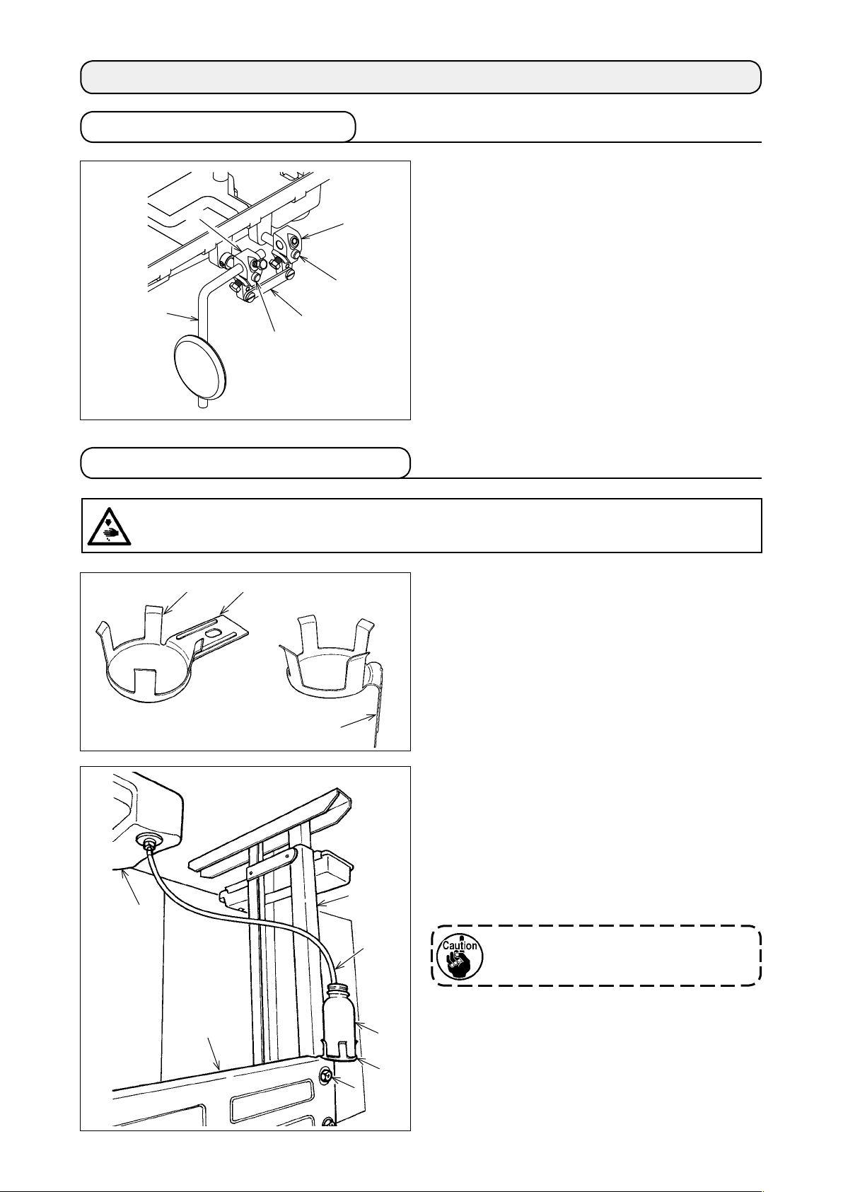
2-2. Installing the waste oil receiver
WARNING :
Turn OFF the power before starting the work so as to prevent accidents caused by abrupt start of the
sewing machine.
toward you.
together
❶
❻
❶ A
⇩
A
❸
❼
1) Fold mounting section
of waste oil receiver
A
bracket ❶ at a right angle.
2) Remove one lateral bracing strut setscrew
Insert folded mounting section A of waste oil re-
ceiver bracket ❶ into the section between strut
and lateral bracing strut ❹.
❸
3) Tighten lateral bracing strut
and waste oil
❹
receiver bracket ❶ with lateral bracing strut set-
screw ❷ together.
Firmly tighten lateral bracing strut set-
screw ❷.
❷
.
❹
❷
❺
❶
4) Place waste oil receiver
bracket ❶. Insert tube ❼ coming from oil pan
into waste oil receiver ❺.
* Adjust the length of tube
tance between oil pan ❻ and waste oil receiver
.
❺
– 2 –
on waste oil receiver
❺
according to the dis-
❼
❻
Page 5
2-3. Lubrication
WARNING :
Turn OFF the power before starting the work so as to prevent accidents caused by abrupt start of the
sewing machine.
❷
❶
2-4. Oiling state
❶
1) Fill the oil tank with oil up to line H
❶
.
2) Carry out periodical inspection while the sewing
machine is in use to check the oil quantity. If the
oil surface level is below line L ❷, add oil until
the oil surface reaches line H ❶.
(Use "spindle oil".)
Run the sewing machine to check how oil splashes
on oil sight glass ❶.
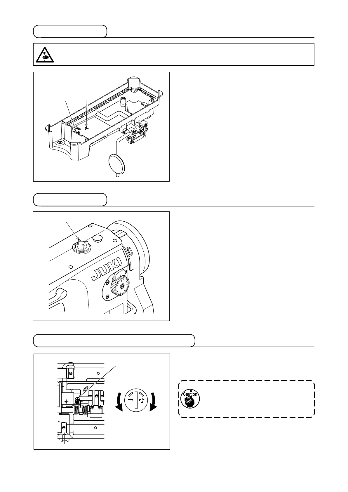
2-5. Adjusting the amount of oil in the hook
❶
Decrease
Increase
– 3 –
Turn screw ❶ to adjust the oil quantity.
Turning screw ❶ in the "+" direction increases the oil
quantity, or in the "−" direction decreases it.
After adjusting the oil quantity with the
screw, run the sewing machine idle for 30
seconds or more. Then, check the oil be-
ing splashed from the hook.
Page 6

2-6. Adjusting the oil in the pump
❶
❷
2-7. Installing the synchronizer
❷
❶
1) In the standard state, bypass hole ❷ is fully
closed with adjusting plate ❶.
2) The wider bypass hole ❷ is opened, the less the
oil quantity becomes.
❸
❹
❺
1) Screw whirl-stop ❺ into the tapped hole in the
arm in the gure and x it with nut ❻.
2) Mount synchronizer ❶ on handwheel ❷.
3) Move whirl-stop ❺ to adjust the position at which
the needle stops.
Determine the stop position by adjusting the in-
❻
* Needle-up stop position
Align white marker dot ❸ on the handwheel with
black marker dot ❹ on the machine arm.
* Needle-down stop position
Align black marker dot ❸ on the handwheel with
black marker dot ❹ on the machine arm.
stalling angle of the synchronizer ❶.
2-8. Installing the belt cover and the bobbin winder
WARNING :
Turn OFF the power before starting the work so as to prevent accidents caused by abrupt start of the
sewing machine.
1) Bore wood-screw guide holes A, B, C and D in
45
❷
❸
❶
❺
❹
❻
D
38
38
3
3
45
26
26
53
53
(mm)
(mm)
C
A
169.5
169.5
B
the table.
2) Fit belt cover struts ❶ and ❷ in tapped holes in
the machine arm.
3) Adjust the position of bobbin winder ❸ and x it
in guide holes A and B with wood screws.
4) Temporarily x belt cover C ❹ in guide holes C
and D.
5) Mount belt cover A ❺ and belt cover B ❻ to
struts ❶ and ❷.
6) Adjust the position of belt cover C ❹ and fix it
with the wood screw.
– 4 –
Page 7

3. HOW TO ADJUST AND HOW TO USE THE SEWING MACHINE
3-1. Attaching the needle
WARNING :
Turn OFF the power before starting the work so as to prevent accidents caused by abrupt start of the
sewing machine.
The standard needle is DPx17. DBx1 needle is also
applicable.
1) Turn the handwheel to move the needle bar up to
❷
A
❶
its highest position.
2) Loosen needle clamping screw
, and hold nee-
❷
dle ❶ so that long groove A in needle ❶ faces
exactly to the left.
3) Insert the needle into the needle
bar until it will
❶
go no further. Securely tighten the needle clamp-
ing screw ❷.
3-2. Threading the machine head
WARNING :
Turn OFF the power before starting the work so as to prevent accidents caused by abrupt start of the
sewing machine.
❶
❷
❸
❹
❽
❼
❾
❺
❻
Bring the thread take-up
lever to its highest position.
Thread the machine head
according to the numbers in
the gure in the numerical
order.
– 5 –
Page 8

3-3. Adjusting the stitch length and reverse-feed stitching
❶
To change the stitch length, press push-lever ❶ and
turn stitch dial ❷.
[Reverse feed stitching]
Push reverse feed lever ❸ down. The machine per-
forms reverse feed stitching as long as the lever is
held depressed.
❷
Release the lever, and the machine will immediately
resume the forward stitching mode.
❸
3-4. Indication of the direction of rotation of the bobbin case
Fit a bobbin ❶ in bobbin case ❷ to allow bobbin ❶
Rotation
direction of
the bobbin
A
❶
to turn in the direction of the arrow when drawing
bobbin thread A.
❷
3-5. Thread tension
WARNING :
Turn OFF the power before starting the work so as to prevent accidents caused by abrupt start of the
sewing machine.
1) Adjusting the needle thread tension
toward A to increase the nee-
❶
toward A to in-
❷
B
❶
A
B
❷
Turn tension nut
dle thread tension, or toward B to decrease it.
2) Adjusting the bobbin thread tension
Turn thread tension screw
crease the bobbin thread tension, or toward B to
decrease it.
A
– 6 –
Page 9

3-6. Presser foot pressure
❶
❷
1) Adjust the pressure of the presser foot according
2) The pressure of the presser foot
3-7. How to install the intermediate presser
Tighten screw ❷ while shifting intermediate presser
❶
to the sewing product.
and that of
❶
the walking foot ❷ can be adjusted separately.
* Use the machine with the minimum pressure
which is necessary.
upward.
3-8. Hand lifter
❷
❶
Turning presser bar lifting lever ❶ in the direction of
arrow A lifts the presser foot.
❶
A
– 7 –
Page 10

3-9. Height of the feed dog
WARNING :
Turn OFF the power before starting the work so as to prevent accidents caused by abrupt start of the
sewing machine.
❷
1mm
1mm
from the surface of throat plate ❷.
When the feed dog height needs to be adjusted ac-
cording to the sewing specications or after the feed
Feed dog ❶ is factory-adjusted to jut out 1.0 mm
❶
dog is replaced, do as follows :
1) Loosen screw
2) Move feed bar
❹
❸
3-10. Adjusting the inclination of the feed dog
WARNING :
Turn OFF the power before starting the work so as to prevent accidents caused by abrupt start of the
sewing machine.
The feed dog has been factory-adjusted so that it is
levelled (horizontal state).
Adjust the inclination of the feed dog according to
the sewing conditions.
1) Loosen feed rock shaft crank setscrew
2) Turn the eccentric shaft in direction
3) After the adjustment, rmly tighten feed rock shaft
❷
Marker dot
A
B
❶
.
❸
up and down to adjust the
❹
height of the feed dog. Then, rmly tighten the
clamping screw.
.
❶
(to lower
A
the front section) or direction B (to raise the front
section) while pressing the slot in eccentric shaft
with a screwdriver.
❷
crank setscrew ❶.
Position of marker dot on
eccentric shaft
Standard
Directly above
Directly below
Feed dog
Standard
3-11. Adjusting the stitch length for forward stitching and reverse stitching
WARNING :
Turn OFF the power before starting the work so as to prevent accidents caused by abrupt start of the
sewing machine.
(four).
❶
with a screwdriver
with a screwdriver
❶
A
B
❷
1) Loosen mounting base setscrews
2) Turning stitch adjusting pin
❷
in direction A increases the stitch length for for-
ward stitching.
3) Turning stitch adjusting pin
❷
in direction B decreases the stitch length for re-
verse stitching.
4) After the adjustment, rmly tighten mounting base
setscrews ❶ (four).
– 8 –
Page 11

3-12. Adjusting the waling foot and presser foot
WARNING :
Turn OFF the power before starting the work so as to prevent accidents caused by abrupt start of the
sewing machine.
(1) Amount of the alternating vertical movement of the walking foot and presser foot
❶
❷
4) In the case the vertical movement amount of the walking foot and that of the presser foot are adjusted
equally, the lift amount can be adjusted from 2.0 mm to 5.0 mm with the alternating vertical movement dial.
1) Amount of the alternating vertical movement of
the walking foot and presser foot is to be adjusted
with alternating vertical movement dial ❶ on the
top cover.
2) Align the number on the alternating vertical move-
ment dial with marker dot ❷ on the top cover.
3) The number on the alternating vertical movement
dial indicates the lift amount of the walking foot
and presser foot when the vertical movement
amount of the walking foot and that of the presser
foot are adjusted equally.
(2) To change the balance of the alternating vertical movement between the walking foot
and presser foot
The vertical movement amount of the walking foot
❷
❶
and that of the presser foot are equal as standard. It
is possible to slightly reduce the vertical movement
amount of the presser foot according to the sewing
product.
* For example, in the case it is desired to increase
the vertical movement amount of the waling foot
and decrease that of the presser foot
1) Remove rubber plug
of the top cover.
❶
2) Turn the handwheel until the presser foot slightly
goes up from the throat plate and stop there.
3) Loosen walking bar adjusting lever clamping screw
❷
.
4) Since the presser foot comes down to the surface of the throat plate by the spring force, re-tighten walk-
ing bar adjusting lever clamping screw ❷ at that position.
(3)Adjusting the feed pitch of the walking foot
Top feed amount has been adjusted to 1:1 with re-
spect to the bottom feed amount. However, it is pos-
A
❶
B
sible to change the top feed amount with respect to
the bottom feed amount according to sewing condi-
tions.
● Loosen nut ❶. Adjust the position of the block up
and down.
* Upper position → Feed pitch, small
* Lower position → Feed pitch, large
A
B
– 9 –
Page 12

3-13. Needle-to-hook relationship
WARNING :
Turn OFF the power before starting the work so as to prevent accidents caused by abrupt start of the
sewing machine.
❷
Upper
marker line
A
C
❶
B
D
❸
Lower
marker line
❺
❶
❹
❺
0.02 to 0.07mm
❹
❻
1) Positioning the needle bar.
Tighten needle bar connection screw ❸ in needle bar connection ❷ so that the marker line of the needle
bar aligns with the bottom end of needle bar lower bushing ❶ at the lowest position of the needle bar.
(Fourth line A from the bottom for a DB x 1, second line C from the bottom for DP x 17)
After the height of the needle bar has been properly adjusted, check that the needle bar does not
come in contact with the walking foot.
2) Position the needle and the hook.
Adjust so that the specied marker line (third line B from the bottom for a DB x 1 needle, or line D at the
bottom for a DP x 17 needle) on the ascending needle bar aligns with the bottom end of lower bushing
. Further adjust to make hook point ❹ nearly meet the center of needle ❺, and adjust the clearance
❶
between needle ❺ and hook point ❹ to 0.02 to 0.07 mm. Then tighten hook screw ❻.
3) To adjust the hook, remove the throat plate rst. Loosen hook setscrew ❻ with a screwdriver and adjust
the hook position from the throat plate side.
3-14. Feed timing
WARNING :
Turn OFF the power before starting the work so as to prevent accidents caused by abrupt start of the
sewing machine.
1) Standard installing position of feed eccentric cam
and that of walking bar lifting eccentric cam ❷
Screw No. 1
Marker
❷
Main shaft
dot
bevel gear
Screw No. 2
Main shaft
Screw No. 1
❶
Marker dot
❶
are as shown in the gure.
2) To adjust the feed timing, open the top cover and
change the installing position of the feed eccentric cam of the walking foot.
3) Timing is advanced by adjusting feed eccentric
cam ❶ in the direction of the arrow.
Timing is retarded by adjusting it in the opposite
direction of the arrow.
If the timing is too late, needle breakage
can result. Adjust the timing appropriately
according to the stitch length.
– 10 –
Page 13

3-15. Relation between the counter knife and the tip
of the thread trimmer blade (left)
WARNING :
Turn OFF the power before starting the work so as to prevent accidents caused by abrupt start of the
sewing machine.
Blade section
Counter
knife
0.3mm
0.3mm
Thread trimmer
blade (left)
❷
❶
1) The standard position of the thread trimmer and
that of the counter knife are as shown in the g-
ure.
2) If the dimension in the figure is larger than 0.3
mm, a three-thread trimming error can occur
causing slip-off of the needle thread after thread
trimming. So, be careful.
On the other hand, if the dimension is excessively
small, a thread trimming error can be caused. So,
be careful.
* Adjusting the counter knife
Adjust the counter knife by moving counter knife
blade ❶ or knife mounting base ❷ in the direc-
tion A or B.
B
A
3-16. Adjusting the mesh of the knife
WARNING :
Turn OFF the power before starting the work so as to prevent accidents caused by abrupt start of the
sewing machine.
❸
9mm 5mm
9mm 5mm
❶
❷
Position of the thread trimmer (left) ❶ and counter
knife
❷
The standard positioning of the thread trimmer (left)
and counter knife ❷ is as illustrated in the gure.
❶
The thread trimmer (left) ❶ should be 9 mm and the
counter knife ❷ should be 5 mm away from the cen-
ter of the needle ❸.
– 11 –
Page 14

3-17. Adjusting the thread trimming cam
1.5~2.0mm
WARNING :
Turn OFF the power before starting the work so as to prevent accidents caused by abrupt start of the
sewing machine.
❸
❺
❶❷
tained when green marker dot ❶ on the handwheel
aligns with marker dot ❷ on the machine arm in the
case the thread trimmer is located at its initial posi-
tion and thread trimming cam ❸ comes in contact
with cam roller ❹.
Loosen thread trimming cam setscrew ❺ and carry
out adjustment.
If the setscrew is not securely tightened,
the thread trimming cam can rotate caus-
ing a faulty thread trimming. So, be care-
ful.
Standard position of the thread trimming cam is ob-
❹
3-18. Adjusting the amount of mesh of the thread trimmer blades
WARNING :
Turn OFF the power before starting the work so as to prevent accidents caused by abrupt start of the
sewing machine.
When knife ❶ reaches its travel end, the standard
depth of mesh between knife ❶ and counter knife ❷
is 1.5 to 2.0 mm.
❹
1.5 to 2.0 mm
❷
❸
❶
1) Turn the handwheel by hand and move the knife
upward.
❶
2) Loosen driving arm clamping screw
adjust the knife mounting base ❹.
3) Securely tighten driving arm clamping screw
. Manually
❸
❸
.
– 12 –
Page 15

3-19. Adjusting the counter knife pressure
WARNING :
Turn OFF the power before starting the work so as to prevent accidents caused by abrupt start of the
sewing machine.
❶
B
1) Loosen locknut ❶ of knife pressure regulating
screw ❷. Turning screw ❷ in direction A lowers
the blade tip to increase the knife pressure.
After the adjustment, tighten the nut.
2) As the thread thickness increases, the knife pres-
sure should be increased. However, it is neces-
sary to minimize the knife pressure as long as the
thread is trimmed by turning the screw in direction
.
B
A
❷
3-20. Auxiliary thread tension
Adjust the auxiliary thread tension with auxiliary
thread tension nut ❶.
1) Direction A to increase the tension →
The remaining length of the needle thread after
thread trimming is shortened
2) Direction B to decrease the tension →
The remaining length of the needle thread after
thread trimming is lengthened.
A
B
❶
3-21. One-touch type manual reverse stitching
❶
1) The sewing machine immediately is brought into
the reverse feed mode and starts reverse stitch-
ing only by pressing switch ❶.
2) Reverse stitching can be carried out as long as
the switch is held pressed.
3) The sewing machine is brought into the normal
feed mode by releasing the switch.
– 13 –
Page 16

4. TROUBLES IN SEWING AND CORRECTIVE MEASURES
Trouble Cause Corrective measure
Thread breakage.
1.
(Thread is untwisted
or scraped.)
(Needle thread re-
mains on the wrong
side of the material
by 2 to 3 cm.)
2. Stitch skipping.
Thread path, needle tip, hook blade tip
①
or bobbin case positioning nger has
aws.
The needle thread tension is excessive.
②
The needle comes in contact with the
③
hook point.
Hook is not lubricated properly.
④
Needle thread tension is too low.
⑤
Thread take-up spring is too tight and
⑥
its stroke is too small.
The timing between the needle and
⑦
hook is too early or too late.
The clearance between the needle and
①
the hook point is too large.
The timing between the needle and
②
hook is too early or too late.
The pressure of the presser foot is too
③
low.
The clearance provided between the
④
top end of the needle eyelet and the
hook blade point is not correct.
The needle number selected is im-
⑤
proper.
When using synthetic thread and thin
⑥
thread.
○ Remove the scratches on the hook point
using a ne emery paper. Finish the bobbin
case positioning nger by bufng.
○ Adjust the needle thread tension properly.
○ Refer to "3-13. Needle-to-hook relation-
ship"p.10.
○ Increase the amount of oil supplied to the
hook according to "2-5. Adjusting the
amount of oil in the hook"p.3.
○ Adjust the needle thread tension.
○ Reduce the tension of the spring and in-
crease the stroke.
○ Refer to "3-13. Needle-to-hook relation-
ship"p.10.
○ Refer to "3-13. Needle-to-hook relation-
ship"p.10.
○ Refer to "3-13. Needle-to-hook relation-
ship"p.10.
○ Tighten the pressure regulator.
○ Refer to "3-13. Needle-to-hook relation-
ship"p.10.
○ Replace the needle with one which is one
count thicker.
○ Wind the needle thread on the needle.
3. Loose stitches.
4. Needle thread slips
out of the needle
eyelet simultaneously with thread trimming.
5. Needle thread cannot be trimmed.
(Bobbin thread can
be trimmed.)
6. Neither the needle thread nor the
bobbin thread are
trimmed.
7. Thread is not
trimmed sharply.
Bobbin thread does not pass through
①
the forked end of the tension spring on
the bobbin case.
Thread path has rough surface.
②
Bobbin does not spin smoothly.
③
Bobbin thread tension is too low.
④
Bobbin is wound too tightly.
⑤
The needle thread cannot be pulled up
⑥
when sewing heavy-weight materials
such as tent fabrics.
Auxiliary thread tension is too high.
①
Thread trimming timing is too early.
②
Returning force of the thread take-up
③
spring is too strong.
Last stitch skips. (Clearance between
①
the needle and the hook is too large)
Thread trimming timing is not correct.
①
Thread trimmer blade breakage
②
Knife pressure is inadequate.
③
Initial position of the thread trimmer is
④
faulty.
Thread trimmer fails to operate.
⑤
Thread trimming solenoid fails to oper-
⑥
ate.
Thread trimming timing is not correct.
①
Knife pressure is inadequate.
②
The blade is not sharp.
③
○ Properly thread the bobbin case.
Grind it using a ne emery paper or buff it up.
○
○ Replace the bobbin or the bobbin case.
○ Decrease the bobbin thread tension.
○ Increase the bobbin thread tension.
○ Retard the feed timing.
Refer to "3-14. Feed timing"p.10.
○ Decrease the auxiliary thread tension.
○ Refer to "3-17. Adjusting the thread trim-
ming cam"p.12.
○ Refer to "3-2. Threading the machine
head"p.5.
Replace the take-up thread guide.
○ Refer to "3-13. Needle-to-hook relation-
ship"p.10.
○ Refer to "3-17. Adjusting the thread trim-
ming cam"p.12.
○ Replace the thread trimmer blade with a
new one.
○ Increase the knife pressure.
○ Refer to "3-17. Adjusting the thread trim-
ming cam"p.12.
○ Manual check is necessary.
○ The motor solenoid operation needs to be
checked.
○ Refer to "3-17. Adjusting the thread trim-
ming cam"p.12.
○ Increase the knife pressure.
○ Replace the thread trimmer blade with a
new one.
– 14 –
 Loading...