

Page 1
R
DU-1181
取扱説明書
使用説明書
INSTRUCTION MANUAL
注意: このたびは、当社の製品を、お買い上げいただきまして、有難うございました。
安全に使用していただくために、使用前に必ずこの取扱説明書をお読みください。
また、いつでもすぐに読めるように、この取扱説明書を保管してください。
NOTE : Read safety instructions carefully and understand them before using.
Retain this Instruction Manual for future reference.
注意 : 為了安全地使用,請您在使用之前一定閱讀本使用說明書。
另外,請您注意保管本使用說明書,以便隨時查閱。
No.01
40021786
Page 2
安全にご使用していただくために
ミシン、自動機、付帯装置(以下機械と言う)は、縫製作業上やむをえず機械の可動部品の近くで作業するた
め、可動部品に接触してしまう可能性が常に存在していますので、実際にご使用されるオペレータの方および、
保守、修理等をされる保全の方は、事前に以下の 安全についての注意事項 を熟読されて、十分理解された
上でご使用ください。この取扱説明書 安全についての注意事項 に書かれている内容は、お客様が購入され
た商品の仕様には含まれない項目も記載されています。
なお、本取扱説明書および、製品の警告ラベルを十分理解していただくために、警告表示を以下のように使
い分けております。これらの内容を十分に理解し、指示を守ってください。
(!)危険の水準の説明
機械操作時、保守時、当事者、第 3 者が取り扱いを誤ったり、その状況を回避し
危険
警告
注意
ない場合、死亡または、重傷を招く差し迫った危険のあるところ。
機械操作時、保守時、当事者、第 3 者が取り扱いを誤ったり、その状況を回避し
ない場合、死亡または、重傷を招く潜在的可能性のあるところ。
機械操作時、保守時、当事者、第 3 者が取り扱いを誤ったり、その状況を回避し
ない場合、中・軽傷害を招くおそれのあるところ。
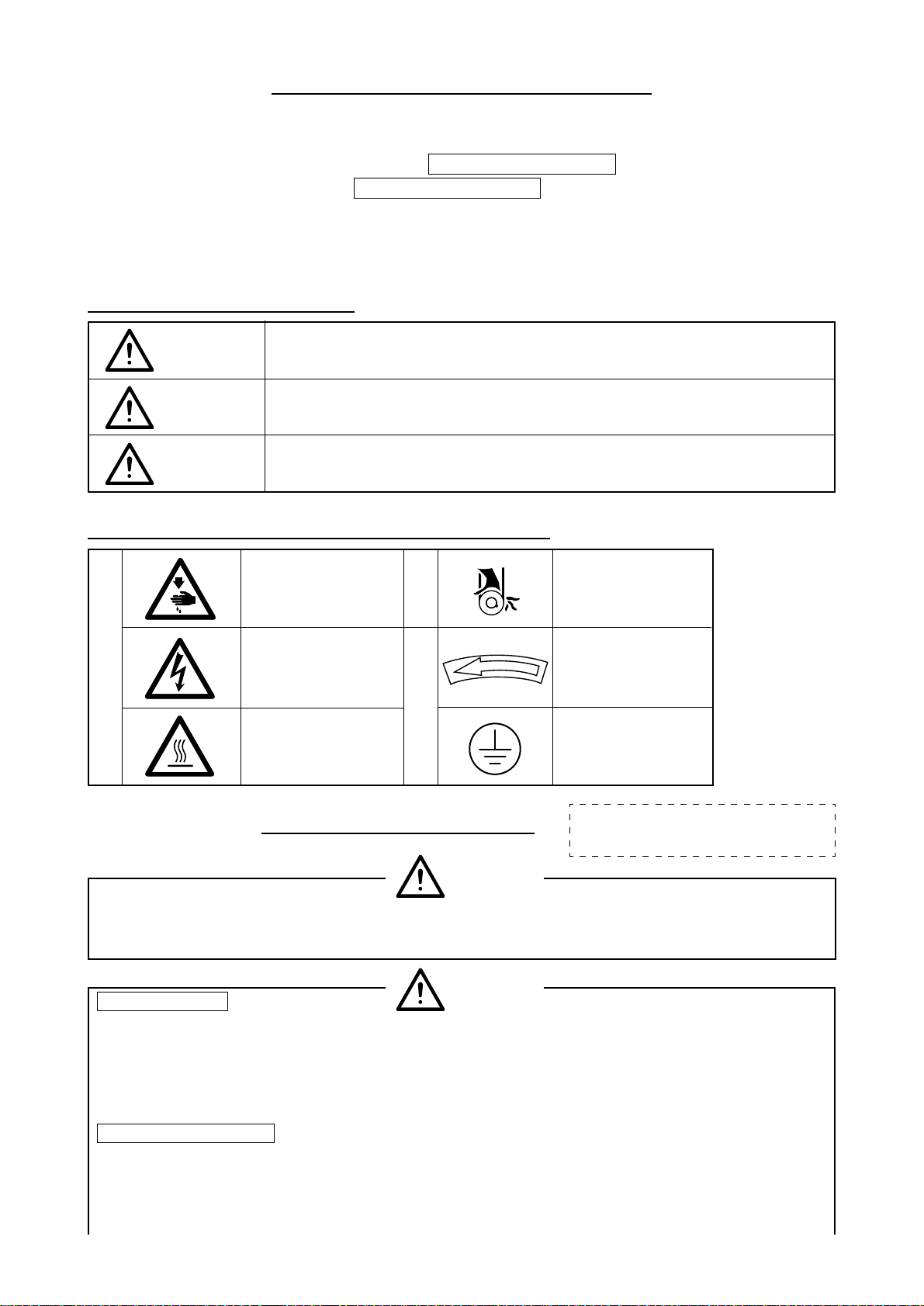
(@)警告絵表示および表示ラベルの説明
運動部に触れて、怪
警
告
絵
表
示
我をする恐れがあり
ます。
高電圧部に触れて、
感電の恐れがありま
す。
高温部に触れて、ヤ
ケドの恐れがありま
す。
指
示
ラ
ベ
ル
安全についての注意事項
ベルトに巻き込ま
れ、怪我をする恐れ
があります。
正しい回転方向を指
示しています。
アース線の接続を指
示しています。
事故とは:人身並びに財産に損害を
与えることをいう。
危険
1. 感電事故防止のため、電装ボックスを開ける必要のある場合は、電源を切り、念のため5 分以上経過し
てから蓋を開けてください。
基本的注意事項
注意
1. ご使用される前に本取扱説明書および、付属に入っている全ての説明書類を必ずお読みください。
また、いつでもすぐに読めるように、この取扱説明書を大切に保存してください。
2. 本項に書かれている内容は、購入された機械の仕様に含まれていない項目も記載されています。
3. 針折れによる事故防止のため、安全眼鏡を着用してください。
安全装置、警告ラベル
1. 安全装置の欠落による事故防止のため、この機械を操作する際は、安全装置が所定の位置に正しく取
り付けられている事を確認してから操作してください。安全装置については、iv頁を参照してくださ
い。
i
Page 3
2. 人身事故防止のため、安全装置を外した場合は、必ず元の位置に取り付け、正常に機能することを確
認してください。
3. 人身事故防止のため、機械に貼り付けてある警告ラベルは、常にはっきり見えるようにしておいてく
ださい。剥がれたり汚損した場合、新しいラベルと交換してください。
用途、改造
1. 人身事故防止のため、この機械は、本来の用途および本取扱説明書に規定された使用方法以外には使
用しないでください。
用途以外の使用に対しては、当社は責任を負いません。
2. 人身事故防止のため、機械には、改造等を加えないでください。改造によって起きた事故に対しては、
当社は責任を負いません。
教育訓練
1. 不慣れによる事故防止のため、この機械の操作についての教育、並びに、安全に作業を行うための教
育を雇用者から受け、適性な知識と操作技能を有するオペレータのみが、この機械をご使用ください。
そのため雇用者は、事前にオペレータの教育訓練の計画を立案し、実施することが必要です。
電源を切らなければならない事項
1. 人身事故防止のため、異常、故障が認められた時、停電の時は直ちに電源を切ってください。
2. 機械の不意の起動による事故防止のため、次のような時は、必ず電源を切ってから行ってください。
2-1. たとえば、針、ルーパ、スプレッダー等の糸通し部品へ糸通しする時や、ボビンを交換する時。
2-2. たとえば、機械を構成する全ての部品の交換、または調整する時。
2-3. たとえば、点検、修理、清掃する時や、機械から離れる時。
3. 感電、漏電、火災事故防止のため、電源プラグを抜く時は、コードではなくプラグを持って抜いてく
ださい。
4. 不意の起動による事故防止のため、クラッチモータを使用している場合は、電源スイッチを切った後
もモータは惰性でしばらく回り続けますので完全に止まっていることを確認してから、上記 2 の作業
を行ってください。
電源を切るとは:電源スイッチを切ってから、電源プラグを
コンセントから抜くことを言う。以下同じ
各使用段階に於ける注意事項
運 搬
1. 人身事故防止のため、機械の持ち上げは 2 人以上で行い、移動には台車等を使用してください。
2. 人身事故防止のため、持ち上げ、移動の際は転倒、落下等を起こさないよう十分安全策をとってくだ
さい。
3. 予期せぬ事故や、落下事故防止のため、再梱包する場合は、着荷時と同じ状態に再梱包してください。
特に機械に付着した油は、十分に拭き取ってから再梱包してください。
開 梱
1. 人身事故防止のため、開梱は上から順序よく行ってください。木枠梱包の場合は、特に釘には十分注
意してください。また、釘は板から抜き取ってください。
2. 人身事故防止のため、機械は重心位置を確かめて、慎重に取り出してください。
据え付け
(Ⅰ)テーブル、脚
1. 人身事故防止のため、テーブル、脚は、純正部品を使用してください。やむをえず、非純正部品
を使用する場合は、機械の重量、運転時の反力に十分耐え得るテーブル、脚を使用してください。
2. 人身事故防止のため、テーブルと脚の固定は、ボルト結合を推奨しますが、木ねじでの固定はφ
5.1×長さ32mm 以上のねじで固定してください。また、下穴を電気ドリル等で深く開けます
と、強度不足となりますので、下穴は喰いつき程度の深さとしてください。固定後、十分なる結
合強度が得られているか、必ず確認してください。
3. 人身事故防止のため、脚にキャスタを付ける場合、十分な強度をもったロック付きキャスタを使
用してください。
ii
Page 4
(Ⅱ)ケーブル、配線
1. 感電、漏電、火災事故防止のため、ケーブルは使用中無理な力が加わらないようにしてください。
また、V ベルト等の運転部近くにケーブル配線する時は、30mm以上の間隔をとって配線して
ください。
2. 感電、漏電、火災事故防止のため、タコ足配線はしないでください。
3. 感電、漏電、火災事故防止のため、コネクタは確実に固定してください。また、コネクタを抜く
時は、コネクタ部を持って抜いてください。
(Ⅲ)接地
1. 漏電、絶縁耐圧による事故防止のため、電源プラグは電気の専門知識を有する人に、適性なプラ
グを取り付けてもらってください。また、電源プラグは必ず接地されたコンセントに接続してく
ださい。
2. 漏電による事故防止のため、アース線は必ず接地してください。
(Ⅳ)モータ
1. 焼損による事故防止のため、モータは指定された定格モータ(純正品)を使用してください。
2. 市販クラッチモータを使用する際は、Vベルトへの巻き込まれ事故防止のため、巻き込み防止付
きプーリカバーが付いたクラッチモータを選定してください。
操作 前
1. 人身事故防止のため、電源を投入する前に、コネクタ、ケーブル類に損傷、脱落、緩み等がないこと
を確認してください。
2. 人身事故防止のため、運動部分に手を入れないでください。また、プーリの回転方向が矢印と一致し
ているか、確認してください。
3. キャスタ付き脚卓を使用の場合、不意の起動による事故防止のため、キャスタをロックするか、アジャ
スタ付きの時は、アジャスタで脚を固定してください。
操作 中
1. 巻き込みによる人身事故防止のため、機械操作中ははずみ車、V ベルト、モータ付近に指、頭髪、衣
類を近づけたり、物を置かないでください。
2. 人身事故防止のため、電源を入れる時、また機械操作中は針の付近や、天びんカバー内に指を入れな
いでください。
3. 機械操作中、釜は高速で回転しています。手への損傷防止のため、操作中は釜付近へ絶対に手を近づ
けないでください。また、ボビン交換の時は電源を切ってください。
4. 人身事故防止のため、機械を倒す時、また元の位置へ戻す時、指等をはさまれないように注意してく
ださい。
5. 不意の起動による事故防止のため、ベルトカバーおよび、Vベルトを外す時は電源を切ってください。
6. サーボモータをご使用の場合は、機械停止中はモータ音がしません。不意の起動による事故防止のた
め、電源の切り忘れに注意してください。
給 油
1. 自動給油の機械には、JUKI マシンオイル No.7 を使用してください。
2. 炎症、カブレを防ぐため、目や身体に油が付着した時は直ちに洗浄してください。
3. 下痢、嘔吐を防ぐため、誤って飲み込んだ場合、直ちに医師の診断を受けてください。
保 守
1. 不慣れによる事故防止のため、修理、調整は機械を熟知した保全技術者が本取扱説明書の指示範囲で
行ってください。また、部品交換の際は、当社純正部品を使ってください。不適切な修理・調整およ
び非純正部品使用による事故に対しては、当社は責任を負いません。
2. 不慣れによる事故や、感電事故防止のため、電気関係の修理、保全(含む配線)は電気の専門知識の有
る人、または当社、販売店の技術者に依頼してください。
3. 不意の起動による事故防止のため、エアーシリンダ等の空気圧を使用している機械の修理や保全を行
う時は、空気の供給源のパイプを外し、残留している空気を放出してから行ってください。
iii
Page 5
4. 人身事故防止のため、修理調整・部品交換等の作業後は、ねじ・ナット等が緩んでいないことを確認
してください。
5. 機械の使用期間中は、定期的に清掃を行ってください。この際、不意の起動による事故防止のため、電
源は必ず切ってから行ってください。
6. 保守、点検、修理の作業のときは、必ず電源スイッチを切り、ミシンおよびモータが完全に停止した
ことを確認してから行ってください。(クラッチモータの場合、電源スイッチを切った後もモータは惰
性でしばらく回り続けますので注意してください。)
7. 人身事故防止のため、修理・調整した結果、正常に操作できない場合は直ちに操作を中止し、当社ま
たは販売店に連絡し、修理依頼してください。
8. 人身事故防止のため、ヒューズが切れた時は、必ず電源を切り、ヒューズ切れの原因を取り除いてか
ら、同一容量のヒューズと交換してください。
使用環境
1. 誤動作による事故防止のため、高周波ウエルダ等強いノイズ源(電磁波)から影響を受けない環境下で
使用してください。
2. 誤動作による事故防止のため、定格電圧± 10% を超える所では使用しないでください。
3. 誤動作による事故防止のため、エアーシリンダ等の空気圧を使用している装置は、指定の圧力を確認
してから使用してください。
4. 安全にお使いいただくために、下記環境下でお使いください。
動作時雰囲気温度 5℃〜 35℃
動作時 相対湿度 35% 〜 85%
5. 電装部品損壊・誤動作による事故防止のため、寒いところから急に暖かいところなど環境がかわった
時、結露が生じることがありますので、十分に水滴の心配がなくなってから電源を入れてください。
6. 電装部品損壊・誤動作による事故防止のため、雷が発生している時は安全のため作業をやめ、電源プ
ラグを抜いてください。
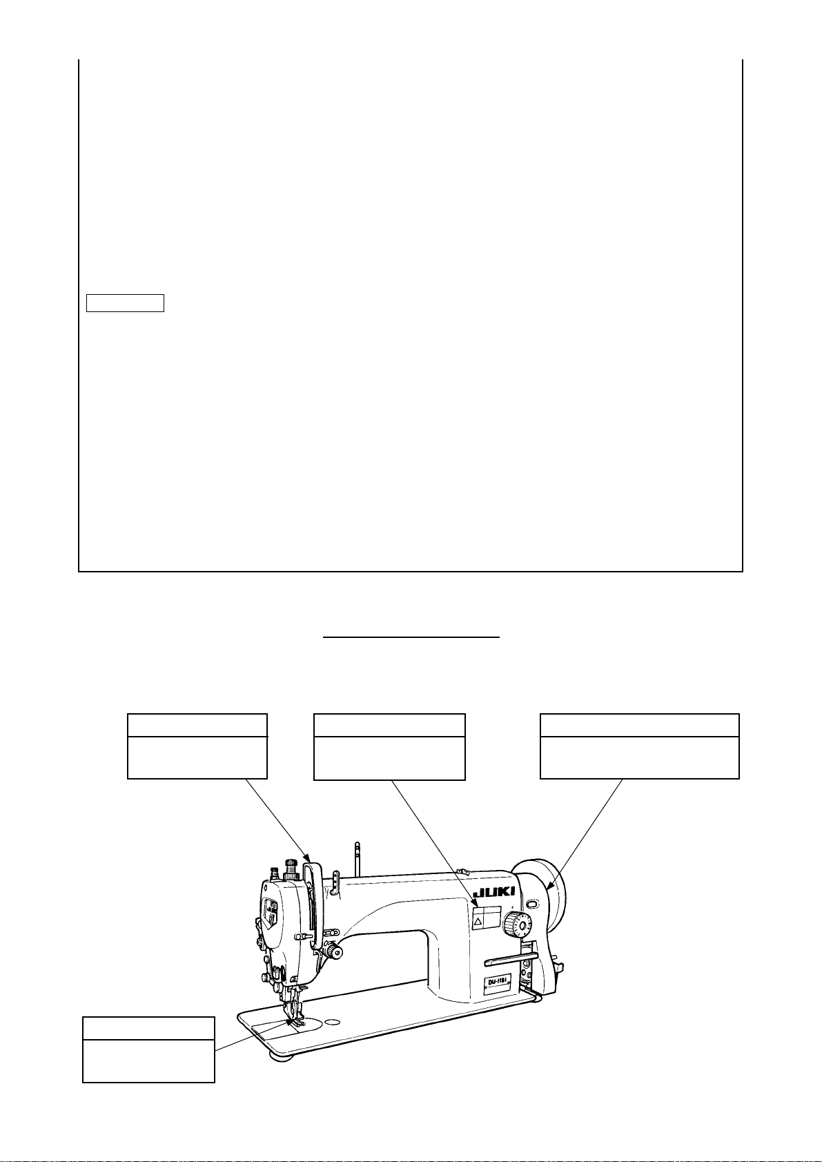
安全装置について
ここに記載されている機械および安全装置はあくまで、日本国内仕様として製造された機種およびそれに装
着・同梱された安全装置であり、仕向地、仕様により異なる場合もあります。
天びんカバー
人体と天びんの接触を
防止するカバーです。
指ガード
安全ラベル
ミシン操作時の最低限の
注意が記載されています。
Vベルトによる手、頭髪、衣類への
巻き込みを防止するカバーです。
ベルトカバー
指と針との接触を防
止するカバーです。
iv
Page 6
危険
より安全にお使いいただくための注意事項
1. 感電による事故を防ぐため、電源を入れたままでモータ電装ボックスの蓋を開けたり、電
装ボックス内の部品に触れないでください。
1. 人身事故防止のため、ベルトカバー、指ガード、等安全装置を外した状態で運転しないで
ください。
注意
2. 巻き込みによる人身事故防止のため、ミシン運転中ははずみ車、V ベルト、モータ付近に
指、頭髪、衣類を近づけたり、物を置かないでください。
3. 人身事故防止のため、電源を入れる時、またミシン運転中は針の付近に指を入れないでく
ださい。
4. 人身事故防止のため、ミシン運転中に天びんカバー内に指を入れないでください。
5. ミシン操作中、釜は高速で回転しています。手への損傷防止のため、運転中は釜付近へ絶
対に手を近づけないでください。また、ボビン交換の時は電源を切ってください。
6. 人身事故防止のため、ミシンを倒す時、また元の位置へ戻す時、指等をはさまないよう注
意してください。
7. 不意の起動による事故防止のため、ミシンを倒す時、またベルトカバーおよび、Vベルト
を外す時は電源を切ってください。
8. サーボモータご使用の場合ミシン停止中はモータ音がしません。不意の起動による事故防
止のため、電源の切り忘れに注意してください。
9. 感電による事故防止のため、電源アース線を外した状態で、ミシンを運転しないでくださ
い。
10. 感電と電装部品損壊による事故防止のため、電源プラグ挿抜の際は、前もって必ず電源を
切ってください。
11. ミシンを倒すときは、テーブルに頭部支え棒がセットされているのを必ず確認してくださ
い。
ミシン運転前のご注意
注意
・ 最初に機械を使用する前にはきれいに掃除しください。
・ 輸送中にたまったほこりを全て取り除いてください。
・ 正しい電圧設定になっているか確認してください。
・ 電源プラグが正しくつながれているかを確認してください。
・ 絶対に電圧仕様の異った状態で使用しないでください。
・ ミシンの回転方向は、プーリー側より見て反時計方向です。逆回転させないように注意してください。
・ 最初の一ヶ月間は縫い速度を落として、1,800rpm以下でお使いください。
機械の誤動作や損傷をさけるために、次の項目を確認してください。
v
Page 7
IMPORTANT SAFETY INSTRUCTIONS
Putting sewing systems into operation is prohibited until it has been ascertained that the sewing systems in
which these sewing machines will be built into, have conformed with the safety regulations in your country.
Technical service for those sewing systems is also prohibited.
1. Observe the basic safety measures, including, but not limited to the following ones, whenever you use the
machine.
2. Read all the instructions, including, but not limited to this Instruction Manual before you use the machine.
In addition, keep this Instruction Manual so that you may read it at anytime when necessary.
3. Use the machine after it has been ascertained that it conforms with safety rules/standards valid in your
country.
4. All safety devices must be in position when the machine is ready for work or in operation.
The operation without the specified safety devices is not allowed.
5. This machine shall be operated by appropriately-trained operators.
6. For your personal protection, we recommend that you wear safety glasses.
7. For the following, turn off the power switch or disconnect the power plug of the machine from the
receptacle.
7-1 For threading needle(s), looper, spreader etc. and replacing bobbin.
7-2 For replacing part(s) of needle, presser foot, throat plate, looper, spreader, feed dog, needle guard, folder,
cloth guide etc.
7-3 For repair work.
7-4 When leaving the working place or when the working place is unattended.
7-5 When using clutch motors without applying brake, it has to be waited until the motor stopped totally.
8. If you should allow oil, grease, etc. used with the machine and devices to come in contact with your eyes or
skin or swallow any of such liquid by mistake, immediately wash the contacted areas and consult a medical
doctor.
9. Tampering with the live parts and devices, regardless of whether the machine is powered, is prohibited.
10. Repair, remodeling and adjustment works must only be done by appropriately trained technicians or
specially skilled personnel. Only spare parts designated by JUKI can be used for repairs.
11. General maintenance and inspection works have to be done by appropriately trained personnel.
12. Repair and maintenance works of electrical components shall be conducted by qualified electric
technicians or under the audit and guidance of specially skilled personnel.
Whenever you find a failure of any of electrical components, immediately stop the machine.
13. Before making repair and maintenance works on the machine equipped with pneumatic parts such as an air
cylinder, the air compressor has to be detached from the machine and the compressed air supply has to be
cut off. Existing residual air pressure after disconnecting the air compressor from the machine has to be
expelled. Exceptions to this are only adjustments and performance checks done by appropriately trained
technicians or specially skilled personnel.
14. Periodically clean the machine throughout the period of use.
15. Grounding the machine is always necessary for the normal operation of the machine. The machine has to
be operated in an environment that is free from strong noise sources such as high-frequency welder.
16. An appropriate power plug has to be attached to the machine by electric technicians. Power plug has to be
connected to a grounded receptacle.
17. The machine is only allowed to be used for the purpose intended. Other used are not allowed.
18. Remodel or modify the machine in accordance with the safety rules/standards while taking all the effective
safety measures. JUKI assumes no responsibility for damage caused by remodeling or modification of the
machine.
19. Warning hints are marked with the two shown symbols.
Danger of injury to operator or service staff
Items requiring special attention
vi
Page 8
FOR SAFE OPERATION
1. To avoid electrical shock hazards, neither open the cover of the electrical box for the motor nor
touch the components mounted inside the electrical box.
1. To avoid personal injury, never operate the machine with any of the belt cover, finger guard or
safety devices removed.
2. To prevent possible personal injuries caused by being caught in the machine, keep your fingers,
head and clothes away from the handwheel, V belt and the motor while the machine is operation.
In addition, place nothing around them.
3. To avoid personal injury, never put your hand under the needle when you turn “ON” the power
switch or operate the machine.
4. To avoid personal injury, never put your fingers into the thread take-up cover while the machine
is in operation.
5. The hook rotates at a high speed while the machine is in operation. To prevent possible injury
to hands, be sure to keep your hands away from the vicinity of the hook during operation. In
addition, be sure to turn OFF the power to the machine when replacing the bobbin.
6. To avoid possible personal injuries, be careful not to allow your fingers in the machine when
tilting/raising the machine head.
7. To avoid possible accidents because of abrupt start of the machine, turn OFF the power to the
machine when tilting the machine head or removing the belt cover and the V belt.
8. If your machine is equipped with a servo-motor, the motor does not produce noise while the
machine is at rest. To avoid possible accidents due to abrupt start of the machine, be sure to
turn OFF the power to the machine.
9. To avoid electrical shock hazards, never operate the sewing machine with the ground wire for
the power supply removed.
10. To prevent possible accidents because of electric shock or damaged electrical component(s),
turn OFF the power switch in prior to the connection/disconnection of the power plug.
11. Be sure to confirm that the machine head support bar is properly set in place before tilting the
machine head.
BEFORE OPERATION
CAUTION :
To avoid malfunction and damage of the machine, confirm the following.
• Before you put the machine into operation for the first time after the set-up, clean it thoroughly.
• Remove all dust gathering during transportation and oil it well.
• Confirm that the power plug has been properly connected to the power supply.
• Confirm that the voltage has been properly set.
• Never use the machine in the state where the voltage type is different from the designated one.
• The direction of rotation of the sewing machine is counterclockwise as observed from the handwheel side.
Be careful not to rotate it in reverse direction.
• For the first month, run the machine at a speed of 1,800rpm or less.
vii
Page 9
重要安全事項
此縫紉機在有的國家(設置場所)由於該國的安全規定而被禁止使用。
同時,技術服務也同樣被禁止。
1. 使用此縫紉機時,必須遵守包括如下項目的基本安全措施。
2. 使用此縫紉機之前,請閱讀本使用說明書在內的所有指示文件。
同時應將此使用說明書妥善保管,以便能夠隨時查閱。
3. 此縫紉機應與貴國的有關安全規定一起使用。
4. 使用此縫紉機和縫紉機動作中,所有的安全裝置應安裝到規定的位置。
沒有安裝規定的安全裝置的縫紉機禁止使用。
5. 此縫紉機應由接受過培訓的操作人員來操作。
6. 使用縫紉機時,建議戴安全防護眼鏡。
7. 發生下列情況時,應立即關掉電源開關,或拔下電源線插頭。
7-1 機針、彎針、分離器等穿線和更換旋梭時。
7-2 更換機針、壓腳、針板、彎針、分離器、送布牙、護針器、支架、布導向器等時。
7-3 修理時。
7-4 工作場所無人了或離開工作場所時。
7-5 使用離合馬達時,請等待馬達完全停止之後再進行。
8. 縫紉機以及附屬裝置使用的機油、潤滑脂等液體流入眼裡或沾到皮膚上時,或被誤飲時,應
立即清洗有關部份並去醫院治療。
9. 禁止用手觸摸打開了縫紉機開關通電的零件或裝置。
10. 有關縫紉機的修理、改造、調整應由受過專門訓練的技術人員或專家來進行。
11. 一般的維修保養應由受過訓練的人員來進行。
12. 有關縫紉機的電氣方面的修理、維修應由有資格的電氣技術人員或專家的監督和指導下進行。
13. 修理、保養有關空氣、氣缸等壓縮空氣的零件時,應切斷空氣壓縮機供氣源後再進行。
如有殘留壓縮空氣時,應放掉壓縮空氣。
但,受過相當訓練的技術人員或專家進行有關調整或確認動作時除外。
14. 縫紉機的使用期間應定期進行清掃。
15. 為了正常安全運轉,應安裝地線。同時應在不受高頻焊接機等強噪音源影響的環境下使用。
16. 電源插頭應用具有電氣專門知識的人來安裝。電源插頭必須連接到接地插座上。
17. 縫紉機指定用途以外不能使用。
18. 對縫紉機的改造、變更應符合安全規格,並採取有效的安全措施。
另外,對於有關改造和變更,JUKI公司概不負責。
19. 本使用說明書上採用以下 2個警告符號。
有損傷操作人員、維修人員的危險。
安全上需要特別加以注意的事項。
viii
Page 10
危險
運轉縫紉機前的注意事項
1. 為了防止發生觸電事故,請不要在打開電源的狀態下,打開電氣箱蓋以 及觸摸電氣箱內
的零件。
1. 為了防止人身事故的發生,請不要在卸下皮帶防護罩、手指防護器等安全裝置的狀態下運
轉縫紉機。
注意
2. 為了防止被卷入機器的人身事故,縫紉機運轉中請不要將手指、頭髮、衣服靠近皮帶輪、
V形皮帶、馬達,也不要把東西放到機器上面。
3. 為了防止人身事故的發生,打開電源時以及縫紉機運轉中,請不要把手指放到機針的附
近。
4. 為了防止人身事故的發生,縫紉機運轉中請不要把手指放到挑線桿外罩內。
5. 縫紉機操作中,旋梭高速地旋轉。為了防止手受到傷害,運轉中請絕對不要把手靠近旋
梭。
6. 為了防止人身事故的發生,放倒縫紉機或返回原來位置時,要注意不要夾住手。
7. 為了防止突然的起動造成人身事故,放倒縫紉機時,或卸皮帶罩和V形皮帶時,請一定關
掉電源。
8. 使用伺服馬達時,縫紉機停止馬達無聲音。為了防止意外的起動造成人身事故,請注意不
要忘記關電源。
9. 為了防止觸電事故,卸下電源地線的狀態,請不要運轉縫紉機。
10. 為了防止觸電和損壞電氣零件,拔電源的插頭時,請先關掉機器電源開。
11. 放倒縫紉機時,請一定確認機台上的機頭支撐桿是否安裝著。
運轉縫紉機前的注意事項
注意
•最初使用縫紉機之前,請把機器打掃干淨。
•清除運送途中積存的灰塵,並加油。
•請確認電壓設定是否正確。
•請確認電源插頭是否正確連接。
•電壓規格不同時,請絕對不要使用。
•縫紉機的轉動方向是,站在飛輪側看為逆時針方向。請注意不要讓縫紉機反向轉轉。
•最初的一個月裡應降低縫製速度,把轉速控制到1,800r.p.m.以下使用。
為了防止機械的錯誤動作或損傷,請確認如下項目。
ix
Page 11

目次
1. 仕様 ...................................................................................................................................... 1
2. ミシンの据え付け ............................................................................................................... 2
3. ベルトカバー・糸巻き装置の取り付け .............................................................................. 2
4. 糸立装置の取り付け ........................................................................................................... 3
5. 給油 ...................................................................................................................................... 4
6. 針の取り付け方 ................................................................................................................... 6
7. 下糸の巻き方 .......................................................................................................................7
8. 下糸の通し方 .......................................................................................................................8
9. ペダルの調整 .......................................................................................................................9
10. 上糸の通し方 .................................................................................................................... 10
11. 糸調子 ................................................................................................................................11
12. 糸取りばね........................................................................................................................ 11
13. 押え圧力の調節 ................................................................................................................ 12
14. 送り歯の高さ .................................................................................................................... 12
15. 送り歯の傾き .................................................................................................................... 13
16. 縫い目長さの調節 .............................................................................................................13
17. 針と釜の関係 .................................................................................................................... 14
18. 押え外足と押え中足の調整............................................................................................. 15
19. 送りと針の関係 ................................................................................................................ 18
20. 押え中足と針の関係 ........................................................................................................ 19
21. 天びん糸取り量の調整 .................................................................................................... 19
22. モータプーリとVベルト ................................................................................................. 20
23. 縫いにおける現象と原因・対策 ..................................................................................... 21
x
Page 12

CONTENTS
1. SPECIFICATIONS .......................................................................................................... 1
2. INSTALLATION .............................................................................................................. 2
3. INSTALLING THE BELT COVER AND THE BOBBIN WINDER .................................... 2
4. INSTALLING THE THREAD STAND .............................................................................. 3
5. LUBRICATION ............................................................................................................... 4
6. ATTACHING THE NEEDLE ............................................................................................6
7. WINDING A BOBBIN ..................................................................................................... 7
8. THREADING THE BOBBIN CASE ................................................................................ 8
9. ADJUST THE PEDAL .................................................................................................... 9
10.THREAD THE MACHINE HEAD .................................................................................. 10
11. THREAD TENSION ...................................................................................................... 11
12. THREAD TAKE-UP SPRING ........................................................................................ 11
13. PRESSER FOOT PRESSURE ..................................................................................... 12
14. HEIGHT OF THE FEED DOG ...................................................................................... 12
15. TILT OF THE FEED DOG ............................................................................................. 13
16. ADJUSTING THE STITCH LENGTH ........................................................................... 13
17. NEEDLE-TO-HOOK RELATIONSHIP.......................................................................... 14
18.ADJUSTING THE WALKING FOOT AND THE PRESSER FOOT............................... 15
19. RELATIONSHIP BETWEEN THE FEED TIMING AND THE NEEDLE POSITION ...... 18
20. RELATIONSHIP BETWEEN THE PRESSER FOOT AND THE NEEDLE ................... 19
21. ADJUSTING THE THREAD TAKE-UP STROKE ......................................................... 19
22. MOTOR PULLEY AND V-BELT ................................................................................... 20
23. TROUBLES IN SEWING AND CORRECTIVE MEASURES ....................................... 21
xi
Page 13

目 錄
1. 規格 ......................................................................................................................................................... 1
2. 縫紉機的安裝 ........................................................................................................................................ 2
3. 皮帶護罩、繞線裝置的安裝............................................................................................................... 2
4. 線架裝置的安裝 .................................................................................................................................... 3
5. 加油 ......................................................................................................................................................... 4
6. 機針的安裝............................................................................................................................................. 6
7. 底線的繞線方法 .................................................................................................................................... 7
8. 底線的穿線方法 .................................................................................................................................... 8
9. 踏板的調節............................................................................................................................................. 9
10. 上線的穿線方法 ...................................................................................................................................10
11. 線張力 ....................................................................................................................................................11
12. 挑線彈簧 ................................................................................................................................................11
13. 壓腳壓力的調整 ...................................................................................................................................12
14. 送布牙的高度 .......................................................................................................................................12
15. 送布牙的傾斜度 ...................................................................................................................................13
16. 縫跡長度的調節 ...................................................................................................................................13
17. 機針和旋梭的關係 ...............................................................................................................................14
18. 外壓腳和中壓腳的調整 ......................................................................................................................15
19. 送布和機針的關係 ...............................................................................................................................18
20. 中壓腳和機針的關係 ..........................................................................................................................19
21. 機針與旋梭的關係 ...............................................................................................................................19
22. 馬達皮帶輪和 V 形皮帶 .......................................................................................................................20
23. 縫製中發生的現象和原因、對策 .....................................................................................................21
xii
Page 14

1. 仕様 /SPECIFICATIONS/ 規格
縫い型式 一本針本縫上下送りミシン 使用針 DP × 17(DB × 1 使用可)
用途 中厚物、厚物 使用針番手 # 14 〜# 23(標準# 21)
縫い速度 最高 2,000r.p.m 使用糸番手 # 40 〜# 8
縫い目長さ 最大 9mm 縫い目調整方式 ダイヤル式
押え上昇量 押え上げレバー:5.5mm、 給油方式 自動給油(上送り手差し)
ひざ上げ:15mm 使用モータ 400 Wクラッチモータ(4P)
天びん リンク天びん 使用油 JUKIマシンオイル No.7
針棒ストローク 36.5mm
Type of sewing
machine head
Application
Sewing speed
Stitch length
Lift of presser foot
Thread take-up lever
Needle bar stroke
1-Needle, Top and Bottom Feed
Lockstitch Machine
For medium and heavy-weight materials
Max. 2,000 rpm
Max. 9 mm
Hand lifter 5.5 mm, Knee lifter 15 mm
Link-type thread take-up lever
36.5mm
縫製形式 單針平縫上下傳送縫紉機
用途 中厚料、厚料
縫製速度 最高 2,000r.p.m
縫跡長度 最大 9mm
壓腳上昇量 壓腳提昇桿:5.5mm 、
膝動提昇:15mm
挑線桿 環形挑線桿
Needle to be used
Needle system
Thread
Stitch adjusting method
Lubrication method
Motor to be used
Oil be used
DP x17 (DB x 1 can be used.)
#14 - #23 (Standard #21)
#40 - #8
Dial
Automatic lubrication
(top feed : manual)
400W clutch motor (4P)
JUKI Machine Oil No.7
使用機針 DP × 17(可以使用 DB × 1)
使用針號 #14 ∼ #23(標準 #21)
使用線號 #40 ∼ #8
縫跡調整方式 撥盤式
加油方式 自動加油(上傳送手加油)
使用馬達 400W 離合馬達(4P)
使用機油 JUKIMachineoilNo.7
針桿行程 36.5mm
1
Page 15

2. ミシンの据え付け /INSTALLATION/ 縫紉機的安裝
7
7
3
22.5 mm
2
1
1
A
4
B
3
1
18.5 mm
3
7
4
5
6
5
(1) オイルパンの取り付け
1) テーブル溝の四隅でオイルパンを支えるようにしてください。
2) 手前側 Aの2つは頭部支えゴム座 1 を釘 2 でテーブルの張り出した部分に打ちつけ、ヒンジ側
B の2つは頭部クッション座 3 を釘で打ちつけて固定し、オイルパン 4 をのせてください。
3) ヒンジ5をベッドの穴に入れ、テーブルのゴムヒンジ6にかみ合わせて、頭部を四隅の頭部クッ
ション 7 の上におろしてください。
7
(1) Installing the under cover
1) The under cover should rest on the four corners of the machine table groove.
2) Two rubber seats 1 for supporting the head portion on the operator side A are fixed on the extended
portion of the table by hitting the nail 2 , and the other two rubber cushion seats 3 on the hinge side B
are fixed by using a rubber-based adhesive. Then, oil pan 4 is placed.
3) Fit hinge 5 into the opening in the machine bed, and fit the machine head to table rubber hinge 6 before
placing the machine head on cushions 7 on the four corners.
(1)底槽的安裝
1) 把底槽支到機台溝的四角上。
2) 用螺釘 2 把前側 A 的2個頭部橡膠支座 1 釘到機台的伸出部,再用螺釘 2 把鉸鏈側 B 的2個頭
部膠墊座 3 釘好固定,然後把底槽 4 放上去。
3) 把鉸鏈 5 放到機台的孔上,對準台板橡膠支座 6 ,把頭部放到四角的機頭膠墊 7 上。
3. ベルトカバー・糸巻き装置の取り付け /
INSTALLING THE BELT COVER AND THE BOBBIN WINDER /
皮帶護罩、繞線裝置的安裝
不意の起動による人身の損傷を防ぐために電源を切り、モータの回転が止まったことを確認し
注意
WARNING :
To avoid possible personal injury due to abrupt start of the machine, turn off the power to the machine
and check to be sure that the motor has totally stopped rotating in prior.
てから行ってください。
注意
為了防止突然啟動造成人身事故,請關掉電源,確認馬達確實停止轉動後再進行。
2
Page 16

3
2
1
47
63.5
75.5
(mm)
(取り付け順序)
1) Vべルトをミシンプーリに掛けてお
きます。
2) ベルトカバー支柱 1 をアームに取
33
62
り付けます。
3) ベルトカバー2をアームと支柱に
取り付けます。
4) 糸巻装置3 をベルトカバーの中に
入れ、アームおよびベルトカバーに
接触しない位置に調整し、木ねじで
固定します。
5) プーリの手持ち部分をねじで取り付
けます。
(Installing procedure)
1) Put the V belt on the pulley of the
sewing machine.
2) Attach belt cover support 1 on the arm.
3) Attach belt cover 2 on the arm and the
support.
4) Place bobbin winder 3 in the belt cover,
and position it so that it does not contact
the machine arm or the belt cover
before fixing it with wooden screws.
5) Attach the pulley which is held by hand
with screws.
(安裝順序)
1)首先把 V 形皮帶掛到縫紉機皮帶輪上。
2)把皮帶護罩支柱 1 安裝到機架上。
3)把皮帶護罩 2 安裝到機架和支柱上。
4)把繞線裝置 3 放到皮帶護罩裡,調整
到不接觸機架和皮帶護罩的位置,然
後用木螺絲進行固定。
5)用螺絲安裝皮帶輪的手持部分。
4. 糸立装置の取り付け /INSTALLING THE THREAD STAND/
線架裝置的安裝
1) 糸立装置を図のように組み付け、テーブルの穴
に取り付けてください。
2
1
2) 糸立装置が動かない程度に止めナット 1 を締
めてください。
3) 天井配線をおこなう場合は、電源コードを糸立
棒 2 の中に通してください。
1) Assemble the thread stand unit, and insert it in the
hole in the machine table.
2) Tighten locknut 1 to fix the thread stand.
3) For ceiling wiring, pass the power cord through
spool rest rod 2.
1)如圖所示那樣組裝線架裝置,再安裝到機台的孔上。
2)擰緊固定螺母
3)進行頂部布線時,請把電源線從線架立桿
1 不讓線架裝置鬆動。
2 中穿線。
3
Page 17

5. 給油 /LUBRICATION/ 加油
不意の起動による人身の損傷を防ぐために電源を切り、モータの回転が止まったことを確認し
注意
WARNING :
To avoid possible personal injury due to abrupt start of the machine, turn off the power to the machine
and check to be sure that the motor has totally stopped rotating in prior.
てから行ってください。
注意
為了防止突然啟動造成人身事故,請關掉電源,確認馬達確實停止轉動後再進行。
(1)ミシンを運転される前に
1) オイルパン1にジューキマシンオイルNo.7を
HIGH マーク A のところまで入れてください。
2) 油面が LOW マーク B 以下にさがったら再注
油してください。
3) 面部矢印で示された個所に適量注油してくだ
さい。(1 日 1 回必ず適量注油してください。)
4) 注油後ミシンを運転しますと、潤滑が正常のと
きは、油窓2 に油が振り掛かるのが見えます。
5) 油が振り掛かる量の多い少ないは油量の多い
少ないには関係ないので心配いりません。
1
2
A
B
(1) Information on lubrication
1) Fill oil pan 1 with JUKI Machine Oil No. 7 up to
HIGH mark A.
2) When the oil level lowers below LOW mark B, refill
the oil pan with the specified oil.
3) Apply an adequate amount of oil to the points
marked with the arrows of the face plate
components. (Be sure to apply an adequate amount
of oil once a day.)
4) When you operate the machine after lubrication,
you will see splashing oil through oil sight window
2 if the lubrication is adequate.
5) Note that the amount of the splashing oil is
unrelated to the amount of the lubricating oil.
(1)運轉縫紉機前
1)請把JUKIMachineOilNo.1機油倒進油槽1裡,
一直加到 HIGH 標記 A 的位置。
2)油槽的油面降到 LOW 標記 B 以下時,請再次補
充機油。
3) 請向面部箭頭所示的部位加入適量的機油。(請1
日一定適量加油 1 次。)
4)加油後運轉縫紉機,如果潤滑正敘時,可以通過
油窗笆看到油的流動。
5)油流動量的多少,與油量的多少無關。
4
Page 18

大
maximum
最大
C
A
1
2
小
minimum
最小
B
4
A
飛散油 /Oil spots/ 飛濺油
[\
飛散油 /Oil spots/ 飛濺油
1mm
4
適量(最少)
Adequate amount
(minimum)
適量(最少)
適量(最多)
Adequate amount
(maximum)
適量(最多)
(2)面部油量調節
1) 油防板止めねじ 1 をゆるめ、油防板2 を取り
外してください。
2)天びん及び針棒クランク部3 への給油調節は油
量調節ピン 4 を回して調節します。
3) 調節ピンの刻点Aが図の位置からB方向に回し
て針棒クランク 3 の近くにきたとき、油量は最
小となります。
4) 図の位置からC方向に回して針棒クランク3と正
反対のところにきたとき、油量は最大になります。
5) 油量調節ピンで調整した後は、30秒間程度の空
運転を行い、油量(跡)確認用紙を矢印方向より
挿入し、油量が適量であることを確認してさい。
(2) Adjusting the amount of oil supplied
to the face plate parts
1) Loosen setscrew 1 in the oil shield plate, and
remove oil shield plate 2.
3
2) Adjust the amount of oil supplied to the thread take-
up and needle bar crank 3 by turning adjust pin 4.
3) The minimum amount of oil is reached when marker
dot A is brought close to needle bar crank 3 by
turning the adjust pin in direction B.
4) The maximum amount of oil is reached when
marker dot A is brought to the position just opposite
from the needle bar crank 3 by turning the adjust
pin in direction C.
5) Make the sewing machine run idle for approximately
30 seconds after adjusting with the adjust pin, insert
a sheet of paper for confirming the oil amount (oil
spots) from the direction of arrow mark, and confirm
that the amount of oil is adequate.
(2)面部油量的調整
1) 請擰鬆防油板固定螺絲 1 ,然後卸下防油板
2 。
2)調整挑線桿和針桿曲軸部3的油量時,轉動油量
調整銷 4 進行調整。
3)調詳銷刻點 A 從圖的位置向 B 方向轉動,轉動到
接近針桿曲軸 3 時,油量最小。
4) 從圖上所示的位置向 C 方向轉動,當轉到與針桿
曲軸 3 的正對面的位置時,油量為最大。
5) 用油量調節銷調整後,請進行 30 秒左右的空運
轉,按照箭頭方向插入確認油量(油跡)專用紙確
認油量是否適量。
5
Page 19

(3)釜の油量調整
A
B
飛散油 /Oil spots/ 飛濺油
適量(最少)
Adequate amount
(minimum)
適量(最少)
[\
飛散油 /Oil spots/ 飛濺油
適量(最多)
Adequate amount
(maximum)
適量(最多)
1mm
1) 下軸前メタルについている油量調節ねじを +
の方向(A 方向)に回すと油量は多くなり、−
の方向(B方向)に回すと油量は少なくなりま
す。適量となるように調整してください。
2)油量調節ねじで調整した後は、30 秒間程度の
空運転を行い、油量(跡)確認用紙を釜下面に 5
秒間挿入して油量の測定を行ってください。
(速度:2000rpm)
(3) Adjusting the amount of oil in the hook
1) Turning the oil amount adjustment screw attached
on the hook driving shaft front bushing in the “+”
direction (in direction A) will increase the amount
of oil (oil spots) in the hook, or in the “–” direction
(in direction B) will decrease it. Adjust so that the
amount of oil is adequate.
2) After the amount of oil in the hook has been properly
adjusted with the oil amount adjustment screw,
make the sewing machine run idle for approximately
30 seconds, and insert a sheet of paper for
confirming the oil amount (oil spots) under the hook
for 5 seconds to measure the amount of oil in the
hook. (Speed : 2,000 rpm)
(3) 旋梭油量調整
1) 把下軸前端金屬部件上的油量調詳螺絲向+的方向(A方向)轉動,油量變多,向-的方向(B方
向)轉動,油量變少。請調整到適量。
2) 用油量調節螺絲調整之後,請進行30秒左右的空運轉,然後把確認油量(油跡)專用紙插入到旋梭下
面5秒鐘,測定油量。(速度:2000rpm)
6. 針の取り付け方 /ATTACHING THE NEEDLE / 機針的安裝
不意の起動による人身の損傷を防ぐために電源を切り、モータの回転が止まったことを確認し
注意
WARNING :
To avoid possible personal injury due to abrupt start of the machine, turn off the power to the machine
and check to be sure that the motor has totally stopped rotating in prior.
注意
1
標準機針是 DP × 17#21 。
1) 轉動飛輪,把針桿上昇到最高部位。
2) 擰鬆機針固定螺絲
3) 把機針深深地插進孔的深處,然後擰緊固定機針固定螺絲。
てから行ってください。
為了防止突然啟動造成人身事故,請關掉電源,確認馬達確實停止轉動後再進行。
標準針はDP× 17#21 です。
1) はずみ車を回して、針棒を最高に上げます。
2) 針止めねじ2 をゆるめ、針 1 の長溝 Aが左真
横にくるように持ちます。
2
3) 針を穴の奥に突き当たるまで深く差し込み、針
止めねじを固く締めます。
The standard needle is a DB x 17 #21.
A
2 ,把機針 1 的長槽 A 轉到橫向朝左。
1) Turn the handwheel to move the needle bar up to
its highest position.
2) Loosen needle clamping screw 2, and hold needle
1 so that long groove A in needle 1 faces exactly
to the left.
3) Insert the needle into the needle bar until it will go no
further. Securely tighten the needle clamping screw.
6
Page 20

7. 下糸の巻き方 / WINDING A BOBBIN /底線的繞線方法
不意の起動による人身の損傷を防ぐために電源を切り、モータの回転が止まったことを確認し
注意
WARNING :
To avoid possible personal injury due to abrupt start of the machine, turn off the power to the machine
and check to be sure that the motor has totally stopped rotating in prior.
てから行ってください。
注意
1
為了防止突然啟動造成人身事故,請關掉電源,確認馬達確實停止轉動後再進行。
1) A、B、Cの順に糸を通し、ボビンに数回巻
きつけます。
2) ボビン押え 1を倒して、糸巻車をベルトに接
触させます。
A
B
2
3
C
3) 糸が八分目位巻けるように糸巻量調節ねじ2で
調節します。糸巻量調節ねじ2を右に回すと糸
巻量は多くなり、左に回すと少なく巻けます。
4) 糸が片寄って巻けるときは、糸巻糸調子棒台
3を左右に動かして、正しく巻ける位置にし
ます。
5) 巻き終わると、ボビン押えが外れて糸巻車は自
動的に止まります。
ミシンを空回しさせる場合は、釜に糸が
からまるおそれがありますので、ボビン
ケース及びボビンを取り外しておいてく
ださい。
1) Route the thread in the order of A, B, and C, and then wind it round the bobbin several times.
2) Set bobbin presser 1 down to make the winder come in contact with the belt.
3) Adjust adjustment screw 2 of the amount of bobbin thread to be wound round the bobbin so that the
bobbin is wound with thread about 80%.Turn the adjustment screw 2 clockwise to increase the bobbin
thread amount or counterclockwise to decrease it.
4) If thread is wound unevenly, move winder tension adjust base 3 to the right or left until it is correctly
positioned.
5) The moment the bobbin has been wound up, the bobbin presser is released, and the bobbin winder will
stop automatically.
Cau tion
1) 按照 A 、 B 、 C 的順序穿線,然後在梭芯上繞數圈線。
2) 放倒梭芯壓片 1 ,讓繞線輪接觸皮帶。
3) 用繞線量調節螺絲 2 進行調節,讓線繞到 80% 。向右轉動繞線量調節螺絲2 繞線量變多,向左轉
4) 繞線時,請左右移動繞線張力桿座 3 ,設定到正確的繞線位置。
5) 繞線結束之後,梭芯壓片分離,繞線輪自動地停止。
注 意
When making the sewing machine run idle, remove the bobbin case and the bobbin since
there is the possibility that thread is entangled in the hook.
動則變小。
讓縫紉機空轉時,有可能機線空繞而卷繞不到旋鎖上,因此請卸下梭殼和梭芯。
7
Page 21

8. 下糸の通し方 / THREADING THE BOBBIN CASE / 底線的穿線方法
不意の起動による人身の損傷を防ぐために電源を切り、モータの回転が止まったことを確認し
注意
WARNING :
To avoid possible personal injury due to abrupt start of the machine, turn off the power to the machine
and check to be sure that the motor has totally stopped rotating in prior.
てから行ってください。
注意
1) Removing the bobbin case
Raise the bobbin case latch to remove the
bobbin case.
2) Threading the bobbin case
1. Pass the thread through threading slit 1 in the
bobbin case, and route it under tension spring 2.
2. Hold the latch of the bobbin case, and set the
bobbin case into the hook.
Place the bobbin in the bobbin case
taking care of the winding direction of
Cau tion
the thread.
(The bobbin should turn in the direction of arrow B when the thread is
pulled in the direction of arrow A.)
為了防止突然啟動造成人身事故,請關掉電源,確認馬達確實停止轉動後再進行。
1
B
2
A
1) ボビンケースの取りはずし
ボビンケースのつまみを起して取り外してくだ
さい。
2) 下糸の通し方
1. 糸をボビンケースの糸通し口1に通し、糸
調子ばね 2 の下をくぐらせてください。
2. ボビンケースのつまみを持って釜に入れて
ください。
ボビンケースにボビンをセットするとき、
糸の巻方向に注意してください。
(糸を矢印A方向に引くと、ボビンが矢印
B方向に回るのが正しい入れ方です。)
1) 梭殼的裝卸
扳起梭殼的卡頭,進行安裝和拆卸。
2) 底線的穿線方法
1. 把線穿過梭殼的穿線口 1 ,然後從線張力彈
簧 2 的下面穿過。
2. 用手拿著梭殼的卡頭放到旋梭裡。
往梭殼安裝梭芯時,請注意線的卷繞方
向。
注 意
(如果把線朝箭頭 A 的方向拉之後,梭芯
向箭頭 B 方向轉動的話,則插入方法正
確。)
8
Page 22

9. ペダルの調節 /ADJUST THE PEDAL / 踏板的調節
不意の起動による人身の損傷を防ぐために電源を切り、モータの回転が止まったことを確認し
注意
WARNING :
To avoid possible personal injury due to abrupt start of the machine, turn off the power to the machine
and check to be sure that the motor has totally stopped rotating in prior.
てから行ってください。
注意
1) Installing the link rod
Move pedal adjustment plate 3 to the right or left until motor control lever 1 is leveled and link rod 2 is
vertically positioned.
2) Pedal angle
The pedal angle can be changed as desired by adjusting the length of the link rod.
Loosen the adjustment screw, and adjust the length of the link rod.
為了防止突然啟動造成人身事故,請關掉電源,確認馬達確實停止轉動後再進行。
1) 連結棒の取り付け
モータ制御レバー1 と、連結棒2 がまっす
ぐになるよう踏板調節板3を左右に動かして
1
3
2
ください。
2) ペダルの角度
ペダルの傾きは連結棒の長さを調節することに
より、自由に変えられます。
調整ねじをゆるめ、連結棒を出し入れして行っ
てください。
1) 連接桿的安裝
請左右移動踏板調節板
2) 踏板的角度
調節連接桿的長度,踏板的傾斜角度可以自動地變化。
請擰鬆調整螺絲,拔出或插入連接桿進行調整。
3 ,讓馬達控制桿 1 和連接桿 2 呈一直線狀態。
9
Page 23

10. 上糸の通し方 / THREAD THE MACHINE HEAD / 上線的穿線方法
不意の起動による人身の損傷を防ぐために電源を切り、モータの回転が止まったことを確認し
注意
WARNING :
To avoid possible personal injury due to abrupt start of the machine, turn off the power to the machine
and check to be sure that the motor has totally stopped rotating in prior.
てから行ってください。
注意
!1
為了防止突然啟動造成人身事故,請關掉電源,確認馬達確實停止轉動後再進行。
1
2
!2
!0
9
8
7
!1
!2
!0
6
3
5
4
6
7
3
4
5
上糸は図の順に通します。
Thread the machine head
in the order as illustrated
in the figure.
請如圖所示那樣穿上線。
10
Page 24

11. 糸調子 / THREAD TENSION / 線張力
1) 上糸張カの調節
2) 下糸張力の調節
A
糸調子ナット1をAの方向に回すと上糸張力
は強くなり、Bの方向に回すと弱くなります。
糸調子ねじ2をAの方向に回すと下糸張力は
強くなり、B の方向に回すと弱くなります。
B
1
2
A
B
1) Adjusting the needle thread tension
Turn tension nut 1 toward A to increase the needle
thread tension, or toward B to decrease it.
2) Adjusting the bobbin thread tension
Turn thread tension screw 2 toward A to increase
the bobbin thread tension, or toward B to decrease
it.
1) 上線張力的調節
向 A 的方向轉動線張力螺母 1 之後,上線張力變強,向 B的方向轉動之後,上線張力則變弱。
2) 底線張力的調節
向 A 的方向轉動線張力螺絲 2 之後,底線張力變強,向 B 的方向轉動之後,底線張力則變弱。
12. 糸取りばね / THREAD TAKE-UP SPRING / 挑線彈簧
(1)糸取りばね 1 のストローク量を変えるには、
1) 糸調子台の止めねじ 2 をゆるめます。
2) 糸調子棒 3 を A の方向に回すと大きくなりま
す。
3) B の方向に回すと小さくなります。
(2)糸取りばね 1 の圧力を変えるときは、
1) 止めねじ 2 をゆるめ、糸調子(組)5 を取り外
します。
2) 糸調子棒止めねじ 4 をゆるめて調節します。
3) 糸調子棒3をAの方向に回すと強くなります。
4) B の方向に回すと弱くなります。
綏
絽
3
1
2
1
5
4
(1) Changing the stroke of thread take-up spring 1
1) Loosen setscrew 2.
2) As you turn tension post 3 in direction A, the
stroke of the thread take-up spring will be
increased.
3) As you turn the knob in direction B, the stroke
will be decreased.
(2) Changing the pressure of thread take-up spring 笊
1) Loosen setscrew 2, and remove thread tention
asm 5.
2) Loosen setscrew 4.
3) As you turn tension post 3 in direction A, the
pressure will be increased.
4) As you turn the tension post in direction B, the
pressure will be decreased.
(1)挑線彈簧 1 的行程量調整
1) 擰鬆線張力台的固定螺絲 2 。
2) 向 A 的方向轉動線張力桿 3 ,則行程量變
大。
3) 向 B 的方向轉動,則行程量變小。
(2)挑線彈簧 1 的壓力調整
1) 擰鬆固定螺絲 2 ,卸下線張力(組件)5 。
2) 擰鬆線張力桿固定螺絲 4 進行調整。
3) 向 A 的方向轉動線張力桿 3 則壓力變強。
4) 向 B 的方向轉動壓力則壓力變弱。
11
Page 25

13. 押え圧力の調節/ PRESSER FOOT PRESSURE / 壓腳壓力的調整
縫製物に応じて、押え中足A(標準 25mm)、押
え外足B(標準15mm)の圧力の調節ができます。
標準 15mm
Standard 15mm
根據縫製物的情況,可以調節中壓腳 A(標準 25mm)、外壓腳 B(標準 15mm)的壓力。
注) 請用需要的最小限度強度的壓力。
標準 25mm
Standard 25mm
注)圧力は必要最小限の強さでご使用ください。
Adjust the pressure applied to presser foot A (standard
height of the presser foot pressure regulator : 25 mm)
and walking foot B (standard height of the walking
foot pressure regulator : 15 mm) according to the type
of material to be sewn.
Note) Use the machine with the minimum pressure
which is necessary.
14. 送り歯の高さ / HEIGHT OF THE FEED DOG / 送布牙的高度
不意の起動による人身の損傷を防ぐために電源を切り、モータの回転が止まったことを確認し
注意
てから行ってください。
WARNING :
To avoid possible personal injury due to abrupt start of the machine, turn off the power to the machine
and check to be sure that the motor has totally stopped rotating in prior.
注意
1
請把距離送布牙 3 的針板 2 的突出量調整到
1.2mm 。
由於縫製條件的需要或送布牙等的更換需要調節
送布牙的高度時:
1. 擰送上下傳送曲柄的緊固螺絲
2. 上下移動送布牙調節高度,然後擰緊緊固螺
絲。
為了防止突然啟動造成人身事故,請關掉電源,確認馬達確實停止轉動後再進行。
3
2
1 。
送り歯3の針板 2 からの突出量は 1.2mm に合わ
せてあります。
縫い条件および、送り歯交換などにより送り歯の
高さを調節するには、
1. 上下送り腕の締めねじ 1をゆるめます。
2. 送り歯を上下に動かして調節し、締めねじを固
く締めます。
Feed dog 3 is factory-adjusted to jut out 1.2 mm from
the surface of throat plate 2.
1.2mm
When the feed dog height needs to be adjusted
according to the sewing specifications or after the feed
dog is replaced, do as follows :
1. Loosen screw 1.
2. Move the feed dog up or down to perform
adjustment, then securely tighten the screw.
12
Page 26

15. 送り歯の傾き / TILT OF THE FEED DOG / 送布牙的傾斜度
不意の起動による人身の損傷を防ぐために電源を切り、モータの回転が止まったことを確認し
注意
WARNING :
To avoid possible personal injury due to abrupt start of the machine, turn off the power to the machine
and check to be sure that the motor has totally stopped rotating in prior.
てから行ってください。
注意
a前上がりb標準c前下がりd針板
aFront up bStandard
cFront down dThroat plate
a前上b標準c前下d針板
採用以下的方法可以調整送布牙的傾斜度。
1)想要向前上方傾斜時,請擰鬆固定螺絲,把螺絲刀插進送布台軸,朝箭頭方向轉動 90°。
2)想要向前下方傾斜時,則請向箭頭相反方向轉動 90°。
為了防止突然啟動造成人身事故,請關掉電源,確認馬達確實停止轉動後再進行。
以下の方法で、送り歯の傾きが調整できます。
a
b
c
d
1) 傾斜を前上がりにするには、止めねじをゆる
め、送り台軸にドライバーを差し込み、矢印方
向に 90°回します。
2) 傾斜を前下がりにするには、反矢印方向に90°
回します。
Tilt of the feed dog can be adjusted with the procedure
described below.
1) To make the tilt front-up, loosen the set screw, insert
a screwdriver into the feed bar shaft, and turn it by
90˚ in the direction of arrow mark.
2) To make the tilt front-down, turn it by 90˚ in the
direction of anti-arrow mark.
16.縫い目長さの調節 /ADJUSTING THE STITCH LENGTH /縫跡長度的調節
送り調節ダイヤル1 を回して希望する数字が上に
くるようにしてピンに合わせます。
[返し縫い]
送りレバー2を下に押します。押している間は、返
し縫いができます。
手を離せば元に戻り、正送りになります。
1
Turn stitch length adjustment dial 1 to bring the
desired value at the top so that the desired value meets
the pin.
[Reverse feed stitching]
2
轉動送布調節撥盤
[倒縫]
向下方按壓送布桿 2 。在按壓的期間可以進行倒縫。
如果手放開送布桿,則返回到原來的狀態,變成正向送布。
1 ,調整到希望的數字。
Push feed lever 2 down. The machine performs
reverse feed stitching as long as the lever is held
depressed.
Release the lever, and the machine will immediately
resume the forward stitching mode.
13
Page 27

17. 針と釜の関係/ NEEDLE-TO-HOOK RELATIONSHIP / 機針和旋梭的關係
不意の起動による人身の損傷を防ぐために電源を切り、モータの回転が止まったことを確認し
注意
WARNING :
To avoid possible personal injury due to abrupt start of the machine, turn off the power to the machine
and check to be sure that the motor has totally stopped rotating in prior.
てから行ってください。
注意
図1/ Fig.1 / 圖1
A
図2/ Fig.2 / 圖2
C
為了防止突然啟動造成人身事故,請關掉電源,確認馬達確實停止轉動後再進行。
1) 針棒の高さを決めます。(図1)
3
2
針棒最下点にて、針棒の刻線と針棒下メタル
1 下端が一致するように針棒抱き 3 締めねじ
1
2 を締めます。
(DB× 1 用…下から 4 番目A、
DP× 17 用…下から 2 番目 B)
1
B
D
1) Positioning the needle bar. (Fig.1)
Tighten needle bar connection screw 2 in needle
bar connection 3 so that the marker line of the needle
bar aligns with the bottom end of needle bar lower
bushing 1 at the lowest position of the needle bar.
(Fourth line A from the bottom for a DB x 1,
Second line B from the bottomFor DP x 17)
針棒高さの調整後は、押え外足と針棒が
当たらないことを確認してください。
5
5
1.3mm
2.5mm
0.02 - 0.07mm
4
4
6
Cau tion
After the height of the needle bar has
been properly adjusted, check that the
needle bar does not come in contact
with the walking foot.
1) 決定針桿的高度。(圖 2)
在針桿最下點,讓針桿下金屬部件1對準針桿的
刻線,然後擰緊針桿套筒 3 緊固螺絲 2 。
(DB × 1 用 ......... 下數第 4 刻線 A ,
DP × 17 用 ......... 下數第 2 刻線 B)
注 意
針桿高度調整後,請確認針桿應不與外壓
腳相碰。
14
Page 28

2) 針と釜の位置を決めます。(図 2)
針棒が上昇するとき、針棒の刻線(DB× 1 用…下から 3 番目 C、DP× 17 用…一番下D)
と針棒下メタル1 を合わせます。釜剣先 4と針 5 の中心がほぼ一致するようにし、針5 と釜剣
先 4 のすき間が 0.02 〜 0.07mm になるように釜止めねじ 6 を締めます。
釜の調整は針板を外し、釜止めねじ 6をゆるめて行ってください。
2) Position the needle and the hook. (Fig.2)
Adjust so that the specified marker line (third line C from the bottom for a DB x 1 needle, or line D at the
bottom for a DP x 17 needle) on the ascending needle bar aligns with the bottom end of lower bushing 1.
Further adjust to make hook point 4 nearly meet the center of needle 5, and adjust the clearance
between needle 5 and hook point 4 to 0.02 to 0.05 mm. Then tighten hook screw 6.
Remove the throat plate, loosen hook screw 6 and adjust the hook.
2) 決定機針和旋梭的位置。(圖2)
針桿上昇時,趟針桿下金屬部件 1 對準針桿的刻線(DB × 1 用…下數第 3刻線 C ,DP×17用…最下
方刻線 D)。
把旋梭尖 4 和機針 5 的中心調整得基本一致,把機針5 和旋梭尖 4 的間隙調整為 0.02
然後擰緊旋梭固定螺絲 6 。
調整旋梭時,請卸下針板,擰鬆旋梭固定螺絲 6 ,然後進行調整。
∼ 0.07mm ,
18. 押え外足と押え中足の調整 /
ADJUSTING THE WALKING FOOT AND THE PRESSER FOOT /
外壓腳和中壓腳的調整
不意の起動による人身の損傷を防ぐために電源を切り、モータの回転が止まったことを確認し
注意
WARNING :
To avoid possible personal injury due to abrupt start of the machine, turn off the power to the machine
and check to be sure that the motor has totally stopped rotating in prior.
注意
(1) 外壓腳的前後位置的調整
1) 把縫跡調到最大,轉動飛輪,在外壓腳 1 前進到最前的位置擰鬆中軸輪緊固螺絲 2 。
2) 移動外壓腳,一直移動到不能頂到中壓腳 3 的背面的位置,緊緊地擰緊中軸輪緊固螺絲 2 。
てから行ってください。
為了防止突然啟動造成人身事故,請關掉電源,確認馬達確實停止轉動後再進行。
(1)押え外足の前後位置の調整
1) 縫い目を最大にして、はずみ車を回し押え外足
1 がもっとも前進した位置で中軸ダルマ締め
2
1
ねじ 2 をゆるめます。
2) 押え中足 3の背面に当らない位置まで押え外
足を動かし、中軸ダルマ締めねじ 2 をきつく
締めます。
(1) Adjusting the longitudinal position of
the walking foot
1) Maximize the stitch length, and turn the handwheel
until walking foot 1 reaches its front end position. Now,
3
loosen screw 2 in the center shaft bell crank.
2) Bring the walking foot as close to presser foot 3 as
possible to the extent that it does not come in contact
with the rear face of presser foot.Securely tighten screw
2 in the center shaft bell crank.
15
Page 29

4
(2)押え外足と押え中足の交互上下運動量
交互運動量は均等が標準です。ただし、縫製物に
よっては押え外足と押え中足の交互運動量を変え
ることがあります。
A
B
1) 上送り腕締めねじ 4 をゆるめます。
2) 天びん最高位置にし、押え上げを下ろします。
3) 上送りダルマを
A に寄せる→押え中足の運動量が大きくなり
ます。
B に寄せる→押え中足の運動量が小さくなり
ます。
(2) Alternate vertical motions of the walking foot and the presser foot
The alternate vertical strokes of the walking foot and the presser foot are normally equal. Depending on the type of
material to be sewn, however, the alternate motions of the walking foot and the presser foot may be changed.
1) Loosen screw 4.
2) Raise the thread take-up to its highest position, and lower the hand lifter.
3) When you move the top feed crank toward A, the vertical stroke of the presser foot will increase.
When you move the top feed crank toward B, the vertical stroke of the presser foot will decrease.
(2) 外壓腳和壓腳的交替上下運動量
標準交替運動量是均等運動量。但是,有的縫製物,有時需要變化外壓腳和中壓腳的交替運動量。
1)擰鬆上傳送曲柄緊固螺絲
2)把挑線桿置於最高位置,下降壓腳。
3)把上傳送輪:向
A 靠近→中壓腳的運動量變大。向 B 靠近→中壓腳的運動量變小。
4 。
(3)押え外足と押え中足の作動高さ
縫製物によって作動高さを変えると有効です。
5
1) ねじ 5 をゆるめて、カムロッドボス位置をか
えます。
A
™ 上位置(A)/作動量大(最大約 5mm)
™ 下位置(B)/作動量小(最小約 2mm)
B
1. 交互上下量最大付近で縫製する場合
は、縫いピッチがばらつく可能性が
あります。その場合は、回転数を下げ
て使用して下さい。
2. 交互上下量を変化させ、厚い縫製物
を縫う場合は、針棒と押え外足が当
たらないことを確認してください。
(3) Operating height of the walking foot and the presser foot
Their height may be changed, depending on the type of material to be sewn.
1) Losen screw 5, and change the position of the cam rod boss.
™ UP position (A) ™ DOWN position (B)
/
operating amount is large. (max. : approx. 5 mm)
Cau tion
1.When sewing is performed near the maximum alternate vertical amount, the sewing pitch
may be uneven. In this case, lower the sewing speed for use.
2. When changing the alternate vertical amount and sewing thick sewing products, check that
the needle bar does not come in contact with the walking foot.
/
operating amount is small. (min. : approx. 2 mm)
16
Page 30

(3) 外壓腳和中壓腳的動作高度
根據縫製物變更了動作高度之後有效。
1)擰鬆螺絲 5 ,變更凸輪凸起位置。
™ 上位置(A)→動作量大(最大約 5mm)
™ 下位置(B)→動作量小(最小約 2mm)
注 意
1. 在最大的交替上下移動量附近縫製時,有可能縫製間距不一致。此時,請降低轉速縫製。
2. 變化交替上下移動量,縫製厚縫製物時,請確認外壓腳應不與針桿相碰。
(4)押え外足の送り量調節
下送り量に対して上送り量は1:1に調整してあ
ります。ただし、縫製条件によっては下送り量に対
する上送り量を変えることができます。
1) ナット6 をゆるめ、角駒の位置を上下に調整
します。
™ 上位置(B)/上送り量小
™ 下位置(A)/上送り量大
(4) Adjusting the feeding amount of the
6
B
A
walking foot
The ration of the bottom feed amount to the top feed
amount is factory-adjusted to 1 : 1. If necessary, the
top feed amount may be changed as follows :
1) Loosen nut 6, and move the slide block up or
down.
™UP position (B) / top feed amount is small.
™DOWN position (A) / top feed amount is large.
(4)外壓腳的送布量調節
上送量與下送量是調整為 1:1 進行縫製。但是,可以根據縫製條件改變上送量與下送量的比例。
1)擰鬆螺母
™ 上位置(B)→上送量小 ™ 下位置(A)→上送量大
6 ,上下調整方塊部件的位置。
17
Page 31

19. 送りと針の関係 /
RELATIONSHIP BETWEEN THE FEED TIMING AND THE NEEDLE POSITION /
送布和機針的關係
不意の起動による人身の損傷を防ぐために電源を切り、モータの回転が止まったことを確認し
注意
WARNING :
To avoid possible personal injury due to abrupt start of the machine, turn off the power to the machine
and check to be sure that the motor has totally stopped rotating in prior.
てから行ってください。
注意
1
はずみ車側 /
Handwheelside /
飛輪側
1〜2枚/
1st or 2nd tooth /
1∼2個
1) Loosen setscrews 2 in the vertical driving cam.
2) Turn the vertical driving cam to the position where throat plate surface 3 and needle tip 4 align with
each other, and the first or the second tooth of the top end of feed dog 5 descends from the throat plate
surface. Then fix the vertical driving cam in place. After this adjustment, loosen setscrews 1 in the feed
driving cam, and align the marker dot A on the feed driving cam with the marker dot A on the vertical
driving cam, and fix the feed driving cam.
(Reference for standard adjustment)
Three points of screws No. 1 in the vertical driving cam and the feed driving cam, and screw No. 2 in the
main shaft thrust collar are nearly aligned.
為了防止突然啟動造成人身事故,請關掉電源,確認馬達確實停止轉動後再進行。
標準的な送りと針の合わせは、目盛りダイヤルが
9mmの時、はずみ車を手前に回して送り歯先端1
〜2枚目が針板上面から沈む瞬間に針先が針板上
面と一致する状態です。
以下の方法で、標準的な合わせに調整します。
1) 上下送りカムの止めねじ 2 をゆるめます。
2) 針板上面 3 と針先 4 が一致し、且つ送り歯 5
の先端 1〜 2 枚目が針板上面から沈む位置に上
下送りカムを回して固定します。その後、水平
送りカムの止めねじ 1 をゆるめ、水平送りカ
ムの刻点Aを上下送りカムの刻点Aに一致さ
せ、水平送りカムを固定します。
(標準の目安)
上下送りカム、水平送りカムの第 1 ねじ、上軸
スラストカラーの第 2 ねじの 3 点がほぼ一致
します。
The standard adjustment is such a state that the needle
tip aligns with the throat plate surface at the moment
when the first or the second tooth of the top end of
feed dog starts descending from the throat plate
surface turning the handwheel toward you with the
scale dial set to 9 mm. Follow the procedure described
below to perform the standard adjustment.
4
2
スラストカラー/
Thrust collar / 滑環
A
3
5
關於標準的送布和機針的調整位置是,刻度撥盤為9mm時,把飛輪轉動到前面,送布牙前端第 1∼2 個
牙從針板上面進入的瞬間,針尖與針板上面對齊的狀態。
用以下的方法,進行標準調整:
1) 擰鬆上下傳送凸輪的固定螺絲 2 。
2) 讓針尖 4 與針板上面 3 對齊,在送布牙 5 的前端 1 ∼ 2 齒從針板上面下沈的位置,轉動上下傳送
凸輪,進行固定。然後,擰鬆水平傳送凸輪的固定螺絲 1 ,把水平傳送凸輪的刻點 A 對準上下傳
送凸輪的刻點 A 。然後固定水平傳送凸輪。
(標準的大埮位置)
上下送布凸輪、水平送布凸輪的第 1 螺絲、上軸滑環的第 2 螺絲的 3 點基本對齊。
18
Page 32

20. 押え中足と針の関係/
RELATIONSHIP BETWEEN THE PRESSER FOOT AND THE NEEDLE /
中壓腳和機針的關係
不意の起動による人身の損傷を防ぐために電源を切り、モータの回転が止まったことを確認し
注意
WARNING :
To avoid possible personal injury due to abrupt start of the machine, turn off the power to the machine
and check to be sure that the motor has totally stopped rotating in prior.
てから行ってください。
注意
3
標準的中壓腳和機針的調整位置是,中壓腳3 和
機針
1 一起下降,中壓腳 3 與針板上面 2 對齊
之後,針孔上端與針板上面
用以下的方法,進行標準調整:
1) 擰鬆上送布凸輪
2) 在針板上面、針孔上端、中壓腳(壓腳面)的 3
點對齊的位置,轉動上送布凸輪,然後固定。
為了防止突然啟動造成人身事故,請關掉電源,確認馬達確實停止轉動後再進行。
5
1
2
4 和固定螺絲 52 個螺絲。
4
2 對齊的狀態。
標準的な押え中足と針の合わせは、針 1 と押え中足
3が下降し、押え中足 3 が針板上面 2 と一致した
時、針穴上端が針板上面2 と一致する状態です。
以下の方法で、標準的な合わせに調整します。
1) 上送りカム4の止めねじ5を2本ゆるめます。
2) 針板上面、針穴上端、押え中足(押え面)の3 点
が一致する位置に上送りカムを回して固定します。
For standard adjustment, the top end of the needle eyelet
aligns with throat plate surface 2 when needle 1
descends and also presser foot 3 descends, and when
the presser foot aligns with throat plate surface 2.
Follow the procedure described below to perform the
standard adjustment.
1) Loosen two setscrews 5 in top feed cam 4.
2) Turn the top feed cam until it reaches the position
to allow the three components such as the throat
plate surface, top end of needle eyelet and presser
foot (pressing plane) to align, and fix the cam at
that position.
21. 天びん糸取り量の調整/ADJUSTING THE THREAD TAKE-UP STROKE/
機針與旋梭的關係
不意の起動による人身の損傷を防ぐために電源を切り、モータの回転が止まったことを確認し
注意
WARNING :
To avoid possible personal injury due to abrupt start of the machine, turn off the power to the machine
and check to be sure that the motor has totally stopped rotating in prior.
注意
てから行ってください。
為了防止突然啟動造成人身事故,請關掉電源,確認馬達確實停止轉動後再進行。
1) 厚物を縫うときは、糸案内1 を A 方向に動かし
BA
1
C
て糸取り量を多くします。
2) 薄物を縫うときは、糸案内1 を B 方向に動かし
て糸取り量を少なくします。
3) 糸案内 1は、刻線 C がねじの中心に一致するの
が標準的な位置です。
19
Page 33

1) When sewing heavy-weight materials, move thread
BA
1
C
guide 1 in direction A to increase the length of
thread pulled out by the thread take-up.
2) When sewing light-weight materials, move thread
guide 1 in direction B to decrease the length of
thread pulled out by the thread take-up.
3) Normally, thread guide 1 is positioned in a way
that marker line C is aligned with the center of the
screw.
1) 縫製厚料時,向 A 的方向移動線導向器 1 ,則挑線量變多。
2) 縫製薄料時,向 B 的方向移動線導向器 1 ,則挑線量變少。
3) 線導向器 1 在刻線 C 對準螺絲的中心時是標準位置。
22. モータプーリとVべルト / MOTOR PULLEY AND V-BELT /
馬達皮帶輪和 V 形皮帶
1.べルトはM型ベルトをご使用ください。
2.モータは 4P、400W をご使用ください。
3.モータプーリとベルトの長さ、ミシンの回転数の関係は次の表のようになります。
ミシン回転数 周波数 モータプーリ外径 Vベルトサイズ
2000r.p.m
50Hz 105mm M43
60Hz 85mm M42
1. モータプーリの有効径は、外径から 5mm 少ない数値となります。
2. 単相モータの場合、べルトは表のサイズより 1 インチ長めのものをご使用ください。
3. 2Pのモータを使用する場合は、モータプーリ外径が50mm以下のものを使用してください。
1. Use an M-type V-belt.
2. Use a motor of 4P, 400W.
3. The relationship between the motor pulley/belt length and the sewing speed of the machine is shown in
the table.
Sewing speed (rpm) Hz Outside diameter of motor puley V-belt length
2000 r.p.m
Cau tion
1.The effective diameter of the motor pulley is obtained by subtracting 5 mm from the outer
diameter.
2.When using a single phase motor, use belts of 1 inch longer than those shown in the right hand table.
3.When using a motor of 2P, use the motor pulley, the outer diameter of which is 50mm or less.
50Hz 105mm M43
60Hz 85mm M42
1.請使用 M 型皮帶。
2.請使用 4P 、 400W 的馬達。
3.馬達皮帶輪、皮帶的長度以及縫紉機轉速的關係如下表所示:
縫紉機轉速 頻率 馬達皮帶輪外徑 V 形皮帶尺寸
2000r.p.m
注 意
1. 馬達皮帶輪的有效直徑為外徑減 5mm 的數值。
2. 單相馬達時,請使用比表中的尺寸長 1 英吋的皮帶。
3. 使用 2P 馬達時,請使用外徑 50mm 以下的馬達皮帶輪。
50Hz 105mm M43
60Hz 85mm M42
20
Page 34

23.繕いにおける現象と原因・対策 /
TROUBLES IN SEWING AND CORRECTIVE MEASURES /
縫製中發生的現象和原因、對策
現象 原因 対策
1. 目飛びする。
2. 糸切れ
(糸がほつれ、または、
すり切れる)
1 上糸経路に異常がある。
2 釜に傷がある。
3 針と釜のタイミングが早い、
または遅い。
4 針と釜剣先のすき間が大きい。
5 押さえ圧が弱い。
6 針番手の選択不良。
1 釜に傷がある。
2 糸取りばねの復帰力が強い。
3 針と釜のタイミングが早い、ま
たは遅い。
4 上糸張力が強い。
5 針と釜剣先が当たる。
™「10. 上糸の通し方」参照
™ 釜剣先の傷は目の細かい紙やすりで
研ぐ。
™「17.針と釜の関係」参照。
™「17.針と釜の関係」参照。
™ 押さえ調節ねじを締める。
™ 1 ランク太番手の針に交換する。
™ 釜剣先の傷は目の細かい紙やすりで
研ぐ。
™ 糸取りばね張力を弱く、動きを大き
くする。
™「17.針と釜の関係」参照。
™ 上糸張力を調節する。
™「17.針と釜の関係」参照。
3. 糸締まり不艮。
(チョウチン)
6 針と釜剣先のすきまが大きい。
1 ボビンケースの糸調子ばねの下
に下糸が入っていない。
2 糸道仕上げが悪い。
3 ボビンの滑りが悪い。
4 下糸張カが強い。
5 下糸張力が弱い。
6 撚りのない化繊糸を使用してい
るとき。
7 針番手の選択
™「17.針と釜の関係」参照。
™ ボビンケースの糸通しを正しくす
る。
™目の細カい紙やすりで研ぐ、または
バフで仕上げる。
™ ボビンの交換、またはボビンケース
の交換。
™ 下糸張力を弱くする。
™ 下糸張力を強くする。
™ 回転数を少し下げる。
(1,800r.p.m.)
™ 1 ランク上の針番手に交換
21
Page 35

Trouble Cause Corrective measure
1. Stitch skipping
2. Thread breakage
1 The machine head has not been
properly threaded.
2 The hook has scratches.
3 The timing between the needle and
hook is too early or too late.
4 The clearance between the needle
and the hook point is too large.
5 The pressure of the presser foot is
too low.
6 The needle number selected is
improper.
1 The hook has scratches.
2 The returning force of the thread
take-up spring is insufficient.
3 The timing between the needle
and hook is too early or too late.
4 The needle thread tension is
excessive.
5 The needle comes in contact with
the hook point.
6 The clearance between the needle
and the hook point is too large.
™ Refer to "10. Threading the machine
heads".
™ Remove the scratches on the hook
point using a fine emery paper.
™ Refer to "17. Needle-to-hook
relationship".
™ Refer to "17. Needle-to-hook
relationship".
™ Tighten the pressure regulator.
™ Replace the needle with one which is
one count thicker.
™Remove the scratches on the hook
point using a fine emery paper.
™ Decrease the tension and increase the
stroke of the thread take-up spring.
™ Refer to "17. Needle-to-hook
relationship".
™ Adjust the needle thread tension
properly.
™ Refer to "17. Needle-to-hook
relationship".
™ Refer to "17. Needle-to-hook
relationship".
3. Loose stitches (Isolated
idling loops)
1 The thread has not been passed
through the notch of the bobbin
case tension spring.
2 The thread path is poorly finished.
3 The bobbin does not rotate smoothly.
4 The bobbin thread tension is too high.
5 The bobbin thread tension is too low.
6 An untwisted synthtic thread is
used.
7 Selection of needle size
™Properly thread the bobbin case.
™Grind it using a fine emery paper or
buff it up.
™Replace the bobbin or the bobbin case.
™ Decrease the bobbin thread tension.
™ Increase the bobbin thread tension.
™ Slightly lower the sewing speed.
(1,800 rpm)
™ Replace with a needle which is thicker
by one.
22
Page 36

現象 原因 對策
1. 跳針。
2. 斷線(綻線或磨斷)
3. 緊線不良。(纏線)
1 上線線路異常。
2 旋梭上有傷痕。
3 機針和旋梭的同步時間過早或過
晚。
4 機針和旋梭尖的間隙過大。
5 壓腳壓力弱。
6 針號選擇不正確。
1 旋梭上有傷痕。
2 挑線彈簧的回復力過強。
3 機針和旋梭的同步時間過早或過
晚。
4 上線張力過強。
5 旋梭尖與機針相碰。
6 機針和旋梭尖的間隙過大。
1 底線不能進入到梭殼的線張力彈
簧下面。
2 線道加工不良。
3 梭芯的滑動性不良。
4 底線張力過強。
5 底線張力過弱。
6 使用了不是多股絞合的化纖線。
7 針號選擇不當。
™ 請參照「10.上線的穿線方法」。
™ 請用細砂紙或銼刀研磨旋梭尖的傷
痕。
™ 請參照「17.機針和旋梭的關係」。
™ 請參照「17.機針和旋梭的關係」。
™ 請擰緊壓腳調節螺絲。
™ 請更換成粗 1 號的機針。
™ 請用細砂紙或銼刀研磨旋梭尖的傷
痕。
™ 調弱挑線彈簧的張力,調大動作行
程。
™ 請參照「17.機針和旋梭的關係」。
™ 請調節上線張力。
™ 請參照「17.機針和旋梭的關係」。
™ 請參照「17.機針和旋梭的關係」。
™ 重新正確地穿梭殼的線。
™ 請用細砂紙或銼刀研磨,或者用拋光
器磨光。
™ 請更換梭芯或更換梭殼。
™ 請調弱底線張力。
™ 請調強底線張力。
™ 請降低轉速。(1,800r.p.m)
™ 更換成大 1 號的機針。
23
 Loading...