

Page 1

ENGLISH
DP-2100/IP-420
INSTRUCTION MANUAL
* "CompactFlash(TM)" is the registered trademark of SanDisk Corporation, U.S.A.
Page 2

CONTENTS
1. SPECIFICATIONS .................................................................................... 1
1-1 Specifications of the machine head ......................................................................1
1-2 Specifications of the control box ...........................................................................1
2. CONFIGURATION .................................................................................... 2
2-1 Sewing machine main unit .....................................................................................2
3. INSTALLATION ........................................................................................ 3
3-1 Caution at the time of set-up ..................................................................................3
3-2 Assembling the pedal section of the stand ..........................................................4
3-3 Assembling the table ..............................................................................................5
3-4 Connecting the power cable ..................................................................................6
3-5 Installing the sewing machine main unit ..............................................................6
3-6 Installing the cover .................................................................................................7
3-7 Installing the stopper for tilt prevention ...............................................................7
3-8 Installing the operation panel ................................................................................7
3-9 Connecting the cords .............................................................................................8
3-10 Installing the throat plate auxiliary plate .............................................................9
3-11 Installing the thread guide rod .............................................................................9
3-12 Installing the thread stand .................................................................................. 10
3-13 Assembling the table for work (WORK TOP TABLE) .......................................10
4. PREPARATION BEFORE OPERATION ................................................ 11
4-1 Attaching the needle ............................................................................................. 11
4-2 Threading the needle-thread ............................................................................... 11
4-3 Winding the bobbin thread ..................................................................................12
4-4 Setting the bobbin into the bobbin case ........................................................... 12
4-5 Attaching and removing the bobbin case ..........................................................13
4-6 Adjusting the thread tension ............................................................................... 13
4-7 Adjusting the thread take-up spring ................................................................... 13
4-8 Adjusting the stitch guide .................................................................................... 13
5. HOW TO USE THE OPERATION PANEL .............................................. 14
5-1. PREFACE ...............................................................................................................14
5-2. BASIC OPERATION OF THE OPERATION PANEL (IP-420) ..............................
(1) Configuration of IP-420 ...................................................................................................................18
(2) Buttons used in common .................................................................................................................
18
19
6.
OPERATION OF THE SEWING MACHINE (SEMI-AUTOMATIC BASIC VOLUME) .................... 20
6-1 Data input screen ..................................................................................................20
6-2 Sewing screen .......................................................................................................22
6-3 Details data input screen .....................................................................................23
6-4 Feed amount .........................................................................................................25
6-5 Basic operation of the sewing machine .............................................................26
(1) Prepare the materials. ......................................................................................................................26
(2) Turn ON the power switch ................................................................................................................
(3) Calling the pattern <Pattern No. selection> .....................................................................................
i
26
26
Page 3

ii
(4) Select left/right alternate sewing. <Left/right alternate sewing selection> .......................................27
(5) Perform sewing. ...............................................................................................................................28
6-6 Basic change of the set value .............................................................................30
(1) Changing the sewing speed <Max. sewing speed setting> .............................................................30
(2) Changing the pitch <Pitch setting> ..................................................................................................30
(3) Changing the needle thread tension <Needle thread tension setting> ............................................31
(4) Changing the shirring amount <Shirring amount setting> ................................................................32
(5) Changing the shirring amount of auxiliary feed
<Auxiliary feed shirring amount setting> .............................. 32
6-7 Creating the pattern <Pattern creation> .............................................................33
6-8 Deleting the pattern <Pattern deletion> .............................................................34
7.
OPERATION OF THE SEWING MACHINE (SEMI-AUTOMATIC APPLICATION VOLUME) .................. 36
7-1 Correcting the pattern ...........................................................................................36
(1)
Changing the needle thread tension of specified step <Compensation thread tension setting> ................................36
(2) Changing the pitch of specified step <Compensation pitch setting> ...............................................37
(3) Increasing/decreasing the shirring amount of all steps <Shirring amount increase/decrease
setting> ............................................................................................................................................38
(4) Increasing/decreasing the shirring amount immediately after changeover of step<Compensation
shirring amount setting> ...................................................................................................................39
(5) Adding the step <Step addition> ......................................................................................................40
(6) Deleting the step <Step deletion> ....................................................................................................42
(7) Changing the start position of program <Start position change> .....................................................44
(8) Mirroring the program of one sleeve and creating the program of the other sleeve <Mirroring
function> .........................................................................................................................................46
(9) Changing the top notch position of program <Top notch position change> .....................................47
(10) Naming the pattern <Data name setting> ......................................................................................49
7-2 Copying the pattern <Pattern copy> ...................................................................50
(1) Pattern copy in semi-automatic mode <Copy to semi-automatic> ...................................................50
(2) Pattern copying from semi-automatic to fully-automatic <Copy to fully-automatic> ........................51
7-3 Creating the new pattern <New pattern creation> .............................................52
7-4 Using the other functions .....................................................................................54
(1) Directly calling the pattern from the sewing screen <Direct pattern selection> ...............................54
(2) Adjust the STEP SELECTION button to the shape of sleeve <Measure function> .........................54
8. OPERATION OF THE SEWING MACHINE (FULLY-AUTOMATIC BASIC
VOLUME) ................................................................................................ 55
8-1 Data input screen ..................................................................................................55
8-2 Sewing screen .......................................................................................................57
8-3 Detailed data input screen ...................................................................................58
8-4 Feed amount .........................................................................................................60
8-5 Basic operation of the sewing machine .............................................................61
(1) Prepare the materials. ......................................................................................................................61
(2) Turn the power ON. ..........................................................................................................................61
(3) Calling the pattern <Pattern No. selection> .....................................................................................61
(4) Selecting left/right alternate sewing <Left/right alternate sewing selection> ....................................62
(5) Performing sewing ...........................................................................................................................62
8-6 Changing the basic set value .............................................................................64
(1) Changing the sewing machine speed <Max. sewing speed setting> ..............................................64
(2) Changing the pitch <Pitch setting> ..................................................................................................65
(3) Changing the needle thread tension <Needle thread tension setting> ............................................65
(4) Changing the shirring amount <Shirring amount setting> ................................................................66
(5)
Changing the shirring amount of auxiliary feed <Auxiliary feed shirring amount setting> ................................. 66
8-7 Creating the pattern <Pattern creation> .............................................................67
8-8 Deleting the pattern <Pattern deletion> .............................................................69
Page 4

9. OPERATION OF THE SEWING MACHINE (FULLY-AUTOMATIC
APPLICATION VOLUME) ....................................................................... 71
9-1 Correcting the pattern ..........................................................................................71
(1) Changing the length of specified step <Length between steps setting> ..........................................71
(2) Changing the needle thread tension of specified step <Compensation thread tension setting> .....72
(3) Changing the pitch of specified step <Compensation pitch setting> ...............................................73
(4) Increasing/decreasing the shirring amount of all steps <Shirring amount increase/decrease
setting> ............................................................................................................................................75
(5) Increasing/decreasing the shirring amount immediately after changeover of step <Compensation
shirring amount setting> ...................................................................................................................76
(6) Adding the step <Step addition> ......................................................................................................77
(7) Deleting the step <Step deletion> ....................................................................................................79
(8) Changing gent's/ladies' wear classification <Gent's/ladies' selection> ............................................81
(9) Changing the size <Size change> ...................................................................................................82
(10) Setting the offset value of grading <Grading value setting> ..........................................................83
(11) Changing the start position of program <Start position change> ...................................................84
(12) Mirroring the program of one sleeve and creating the program of the other one <Mirroring
function> ..........................................................................................................................................85
(13) Changing the top notch position of program <Top notch position change> ...................................87
(14) Naming the pattern <Data name setting> ......................................................................................88
9-2 Copying the pattern <Pattern copy> ...................................................................89
(1) Pattern copy in the fully-automatic <Copy to fully-automatic> .........................................................89
(2) Pattern copy from fully-automatic to semi-automatic <Copy to semi-automatic> ............................91
9-3 Creating a new pattern <New pattern creation> ................................................92
9-4 Using other functions ...........................................................................................94
(1) Directly calling the pattern from sewing screen <Direct pattern selection> .....................................94
(2) Re-registering the length between steps <Measure function> .........................................................95
10. OPERATION OF THE SEWING MACHINE (MANUAL BASIC
VOLUME) ................................................................................................ 96
10-1 Data input screen ................................................................................................96
10-2 Sewing screen ....................................................................................................97
10-3 Details data input screen ...................................................................................98
10-4 Basic operation of the sewing machine ...........................................................99
(1) Prepare the materials. ......................................................................................................................99
(2) Turn the power ON. ..........................................................................................................................99
(3) Perform sewing. ...............................................................................................................................99
10-5 Changing the basic set value ...........................................................................100
(1) Changing the sewing speed <Max. sewing speed setting> ...........................................................100
(2) Changing the pitch <Pitch setting> ................................................................................................101
(3) Changing the needle thread tension <Needle thread tension setting> ..........................................102
11. OPERATION OF THE SEWING MACHINE (MANUAL APPLICATION
VOLUME) .............................................................................................. 103
11-1 Changing the detailed set value .......................................................................103
(1)
Changing the operating mode of auxiliary pedal <Auxiliary pedal operation selection> ........................103
(2) Changing the auxiliary feed operating mode <Auxiliary feed mode selection> .............................104
(3) Setting the auxiliary feed interlock mode <Auxiliary feed interlock mode setting> ........................106
(4) Setting the range of shirring amount <Shirring amount range setting> .........................................108
(5) Setting the compensation thread tension <Compensation thread tension setting> .......................109
12. USING COUNTER .............................................................................. 110
12-1 Setting procedure of the counter ..................................................................... 110
12-2 Count-up releasing procedure ......................................................................... 113
iii
Page 5

iv
13. REGISTERING AND THE PATTERN TO DIRECT BUTTON AND
RELEASING THE PATTERN FROM DIRECT BUTTON ..................... 113
13-1 How to register .................................................................................................. 113
13-2 How to release ................................................................................................... 114
13-3 Register state at the time of your purchase ................................................... 115
14. CHANGING SEWING MODE .............................................................. 115
15. CHANGING MEMORY SWITCH DATA .............................................. 116
15-1 Changing procedure of memory switch data ................................................. 116
15-2 Memory switch data list.................................................................................... 117
15-3 Explanation of compensation thread tension ................................................124
(1) Explanation of compensation tension manual (numerical value) ..................................................124
(2) Explanation of compensation tension manual (level) .....................................................................
(3) Explanation of compensation thread tension automatic ................................................................
15-4 Explanation of the shirring smoothing function ............................................ 131
(1) Explanation of the motion of shirring smoothing function ..............................................................131
(2) Setting of the shirring smoothing function ......................................................................................
15-5 Explanation of the size class ...........................................................................133
(1) Explanation of the size class ..........................................................................................................133
(2) Size development ..........................................................................................................................
126
129
132
135
16. ERROR CODE LIST ........................................................................... 136
17. USING COMMUNICATION FUNCTION ............................................. 140
17-1 Handling possible data .....................................................................................140
17-2 Performing communication by using the media ............................................ 140
17-3 Performing communication by using USB .....................................................140
17-4 Take-in of the data ............................................................................................. 141
18. INFORMATION FUNCTION ................................................................ 144
18-1 Observing the maintenance and inspection information .............................. 144
18-2 Inputting the inspection time ........................................................................... 146
18-3 Releasing procedure of the warning ............................................................... 147
18-4 Observing the production control information ..............................................148
(1) When displaying from the information screen ................................................................................148
(2) When displaying from the sewing screen ......................................................................................
149
18-5 Performing setting of the production control information ............................150
18-6 Observing the working measurement information ........................................ 153
19. PERFORMING FORMATTING OF THE MEDIA ................................. 156
20. TRIAL SEWING FUNCTION ............................................................... 157
20-1 Performing trial sewing ....................................................................................157
21. PERFORMING KEY LOCK ................................................................. 159
22. DISPLAYING VERSION INFORMATION ............................................ 161
23. USING CHECK PROGRAM ................................................................ 162
23-1 Displaying the check program screen ............................................................ 162
23-2 Performing the auxiliary pedal setting ...........................................................163
23-3 Performing checking of A/D value of auxiliary pedal ....................................164
Page 6

23-4 Performing LCD check ..................................................................................... 164
23-5 Performing touch panel compensation .......................................................... 165
23-6 Performing the input signal check ..................................................................167
23-7 Performing the output signal check ................................................................ 169
24. COMMUNICATION SCREEN OF MAINTENANCE PERSONNEL
LEVEL ................................................................................................... 171
24-1 Data which are possible to be handled ........................................................... 171
24-2 Displaying maintenance personnel level ........................................................ 172
25. INFORMATION SCREEN OF THE MAINTENANCE PERSONNEL LEVEL .............173
25-1 Display of error record .....................................................................................173
25-2 Display of the cumulative working information ............................................. 174
26. MAINTENANCE .................................................................................. 175
26-1 Replacing procedure of feed belt .................................................................... 175
(1) Replacing the top feed belt ............................................................................................................175
(2) Replacing the bottom feed belt ......................................................................................................176
(3) Replacing the bottom feed roller ....................................................................................................176
26-2 Changing the amount of alternate vertical movement of walkingfoot and
presser foot ........................................................................................................177
(1) When making equal the amount of alternate vertical movement of walking foot and presser foot
(When making the amount equal to 1.5 mm) .................................................................................178
(2) When making 2.5 mm the amount of alternate vertical movement ...............................................
178
26-3 Adjusting the height of the walking foot and the presser foot ..................... 179
(1) Adjusting the height of walking foot ................................................................................................179
(2) Adjusting the height of presser foot ................................................................................................179
26-4 Adjusting the needle and the hook ................................................................. 180
(1)
Adjusting the height of needle bar ...................................................................................................................180
(2) Adjusting the hook ..........................................................................................................................180
26-5 Adjusting the thread trimmer........................................................................... 181
(1) Adjusting the thread trimmer cam timing ........................................................................................181
(2) Adjusting the initial position of the moving knife .............................................................................
(3) Adjusting the initial position of the thread trimmer solenoid ...........................................................182
(4) Adjusting the position of the moving knife and the counter knife ...................................................
181
183
26-6 Greasing parts ..................................................................................................183
27. OTHERS.............................................................................................. 184
27-1 Troubles in sewing and the corrective measures ..........................................184
28. DRAWING OF THE TABLE ................................................................ 185
28-1 Slant table ..........................................................................................................185
28-2 Work top table ...................................................................................................186
28-3 Edge stopper A ................................................................................................ 187
28-4 Edge stopper B ................................................................................................188
v
Page 7
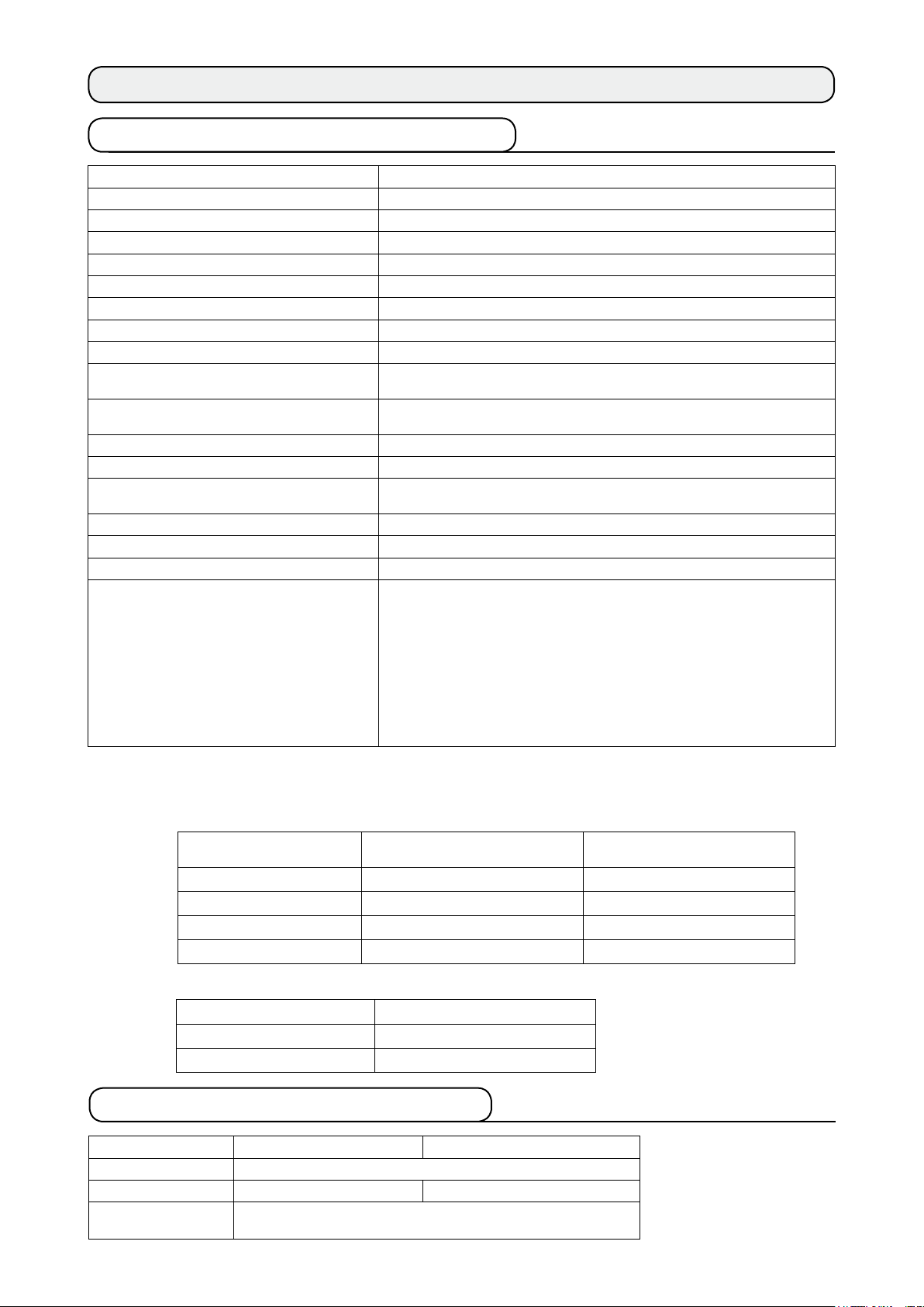
1. SPECIFICATIONS
1-1 Specications of the machine head
Sewing speed Max. 3,500 sti/min (*1)
Feed system
Stitch length Both top and bottom 1.5 to 6 mm
Stitch length adjustment system Panel input
Stitch length adjustment minimum resolution 0.1 mm
Needle bar stroke 30.7 mm
Needle DPX17 #10 to #14
Hook Full-rotary non-lubricated horizontal-axis hook
Presser foot lift By hand lifter : 5.5 mm, by auto-lifter : 10 mm
Amount of alternate vertical movement of
presser foot/walking foot
Adjustment of amount of alternate vertical
movement of presser/walking foot
Lubrication Non-lubrication
Number of programs that can be inputted 99 programs
Number of steps that can be inputted (per
program)
Data mirroring Provided
Right/left alternate sewing Possible
Data record Main body, Media
Noise
Intermittent belt feed by direct drive of stepping motor
Max. 3.5 mm
Slot stop position adjustment
30 steps
- Equivalent continuous emission sound pressure level (LpA) at the
workstation :
A-weighted value of 84.5 dB; (Includes KpA = 2.5 dB); according to
ISO 10821- C.6.2 -ISO 11204 GR2 at 3,400 sti/min for the sewing
cycle, 6.7s ON and 7.5s OFF (Pattern : check_mode4).
- Sound power level (LWA) ;
A-weighted value of 89.5 dB; (Includes KWA = 2.5 dB); according to
ISO 10821- C.6.3 -ISO 3744 GR2 at 3,400 sti/min for the sewing
cycle, 6.7s ON and 7.5s OFF (Pattern : check_mode4).
*1. The maximum sewing speed is limited in accordance with the amount of alternate vertical movement
of presser foot and walking foot, and stitch length.
Limitation by the amount of alternate vertical movement of presser and walking foot
Max. sewing speed (sti/min)
3,500 Less than 0.3 (2.7)
2,600 Not less than 0.3 to 1.5 (1.5)
2,000 Not less than 1.5 to 2.5 (2.5)
1,600 Not less than 2.5 to 3.5 (3.5)
Amount of vertical movement of
walking foot (mm)
Amount of vertical movement
of presser foot (mm)
Limitation by stitch length
Max. sewing speed (sti/min) Stitch length (mm)
3,500 1.5 to 4.0
2,500 4.1 to 6.0
1-2 Specications of the control box
Power voltage 3-phase 200V/220V/240V Single phase 220V/230V/240V
Frequency 50Hz/60Hz
Rated current 2.6A/2.4A/2.2A 2.8A/2.6A/2.5A
Operating temperature/humidity
0 to 40˚C, Less than 90%
–
–
1
Page 8

2. CONFIGURATION
2-1 Sewing machine main unit
4
2
9
1
8
5
3
1
2
3
4
5
6
7
8
9
7
6
Sewing machine head
Operation panel
Control box
Auxiliary table (WORK TOP TABLE)
Power switch
Main pedal
Auxiliary pedal
Thread stand
Shirring release switch
–
–
2
Page 9
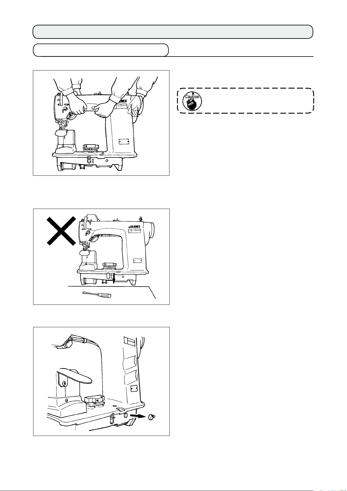
3. INSTALLATION
3-1 Caution at the time of set-up
1) Transporting procedure of the sewing machine
2) Caution when placing the sewing machine
Hold and transport the sewing machine with two per-
sons as shown in the illustration.
Do not hold the handwheel.
Do not put protruding articles such as the screw-
driver and the like at the location where the sewing
machine is placed.
3) Removing the air vent cap
Be sure to remove the red rubber cap as shown in
the illustration before operating the sewing machine.
When transporting the machine head only, attach
this rubber cap to the machine head.
–
–
3
Page 10
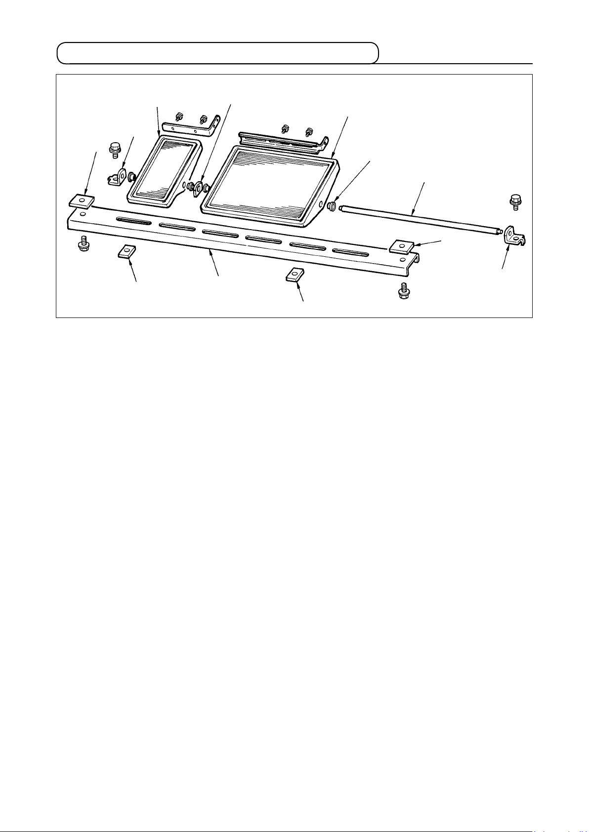
3-2 Assembling the pedal section of the stand
8
2
7
1
1) Assemble the lower strut to the stand using square nut 7(wide width).
2) Put bush 4 to
with
pedal shaft bearing 2.
3) Fix pedal shaft bearing 2
4) Assemble the whole pedal after fully drawing it up in the left direction in the illustration.
the pedal 8 and pass it through shaft 5 together with shaft bearing plate 3. Then x
3
8
4
5
7
6
1
using square nut 1 (narrow width).
2
[When using with 1-pedal]
There is the short shaft for 1-pedal in the accessories. Remove the small pedal and shaft bearing plate
and replace the shaft with the shaft for 1-pedal. Then the machine can be used even with 1-pedal.
3
–
–
4
Page 11
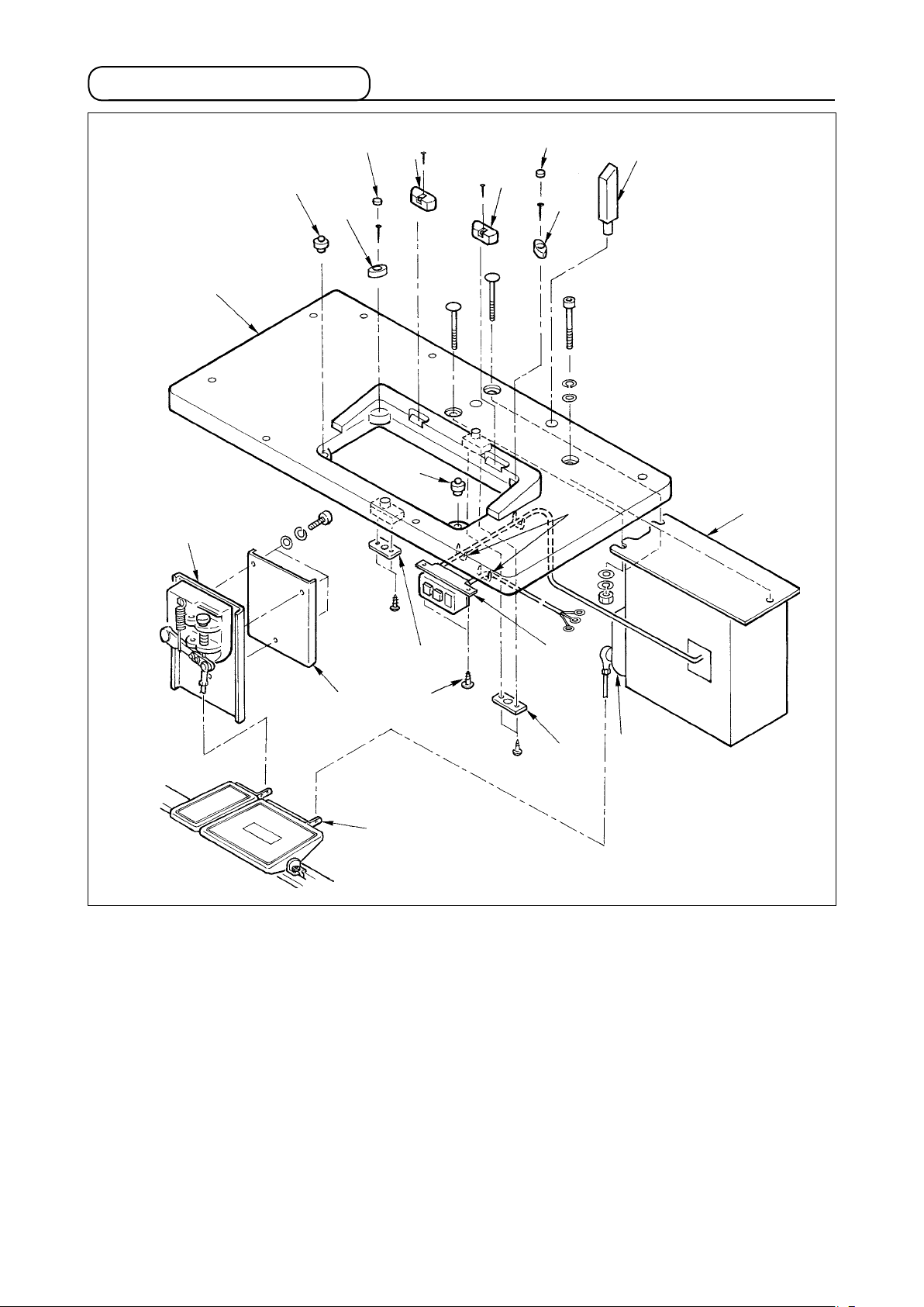
3-3 Assembling the table
!0
1
8
6
7
5
8
5
7
6
!5
4
2
9
!1
!3
1) Fix hinge seats 5 and
each of nail for xing hinge seats 5 and 1 pc. each of nail for xing machine head supporting rubbers.)
2)
Attach felts 7 to machine head supporting rubbers 6.
3) Attach machine head supporting rubbers 8
4)
Fix stopper plate 9
Caution) Be sure to install stopper plate 9 before installing control box 2.
5) Fix control box 2
6) Fix power switch 3
with the machine as accessories in accordance witch the forms of use.
plied
7) Temporarily x the side strut so that it is put between auxiliary pedal sensor !0
Connect pedal (large) and pedal sensor
8)
necting
9) Connect pedal (small) and auxiliary pedal sensor !0
of connecting rod at the position of auxiliary pedal sensor and securely tighten the screw.
10) Install head supporting rod 4
rod at the position of adjusting plate !3.
machine head supporting rubbers 6 on table 1 with the nails. (Use 2 pcs.
to the rear side of table 1.
and power switch 3, and x the power cable with the staples.
under the machine table witch wood screw !4.
on table 1.
!4
to table 1.
with connecting rod (long). Adjust the inclination of con-
!2
with connecting rod (short). Adjust the inclination
3
9
!2
Fix the cable with staple !5 sup-
and sensor plate !1.
–
–
5
Page 12
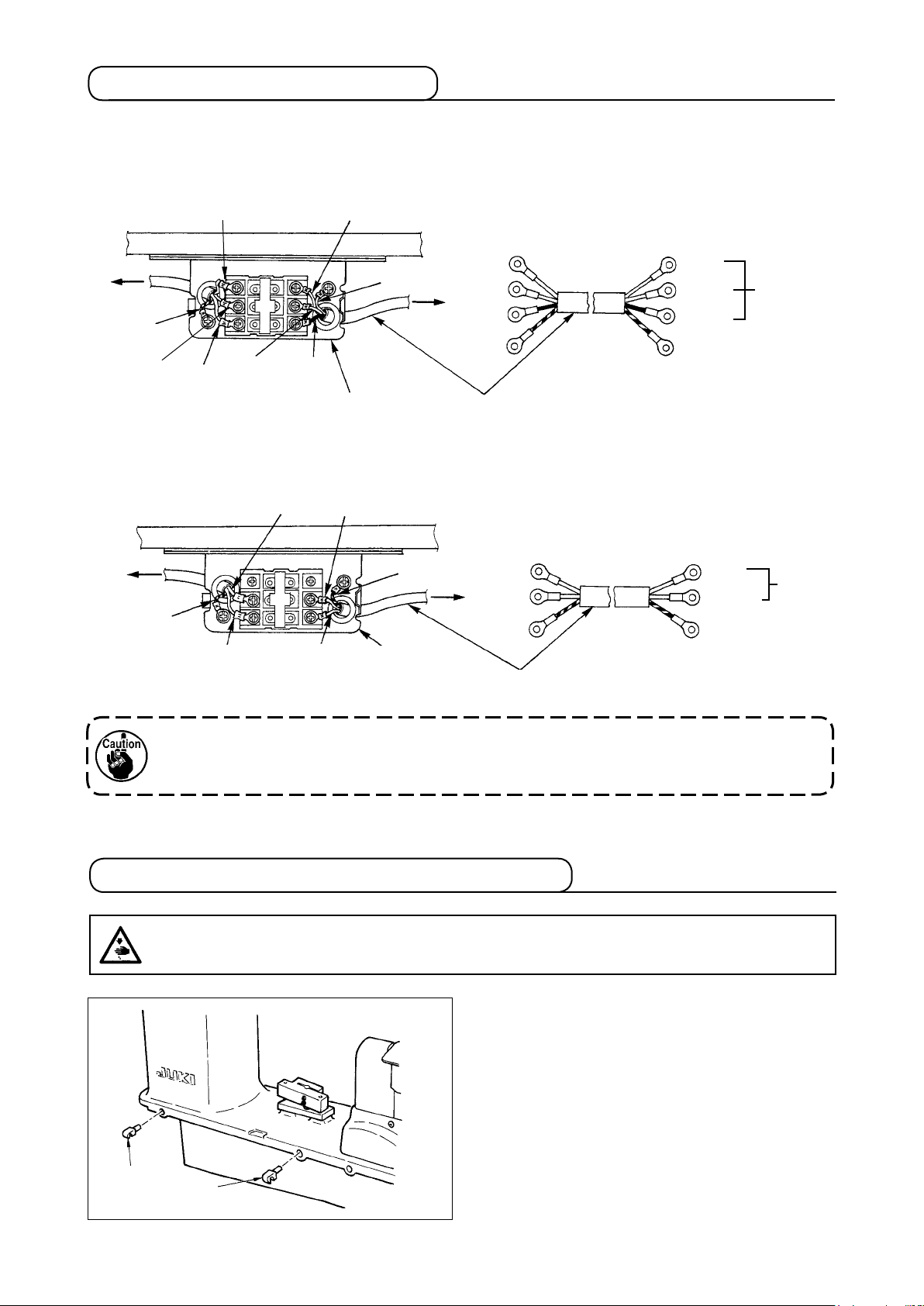
3-4 Connecting the power cable
Connect the cable in accordance with the specications.
• Connection of 3-phase 200V/220V/240V
Red
Red
Table
Control box
Green/Yellow
White
Black
White
Black
Power switch
• Connection of single phase 220V/230V/240V
Light blue
Light blue
Table
Control box
Green/Yellow
Brown
Brown
Power switch
Green/Yellow
Plug
Power source cord
Green/Yellow
Plug
Red
White
Black
Green/Yellow- GND
Brown
Light blue
Green/Yellow- GND
AC200 V
AC220 V
AC240 V
AC220 V
AC230 V
AC240 V
Power source cord
Never use the machine with the wrong power specications.
3-5 Installing the sewing machine main unit
WARNING :
To prevent possible accidents caused by the fall of the sewing machine, perform the work by two
persons or more when the machine is moved.
Insert hinges 1 into the holes in the frame and
place the machine head on the table.
1
1
–
–
6
Page 13

3-6 Installing the cover
WARNING :
When tilting/raising the sewing machine head, perform the work so as not to allow your ngers to
be caught in the machine. In addition, to avoid possible accidents caused by abrupt start of the
machine, turn OFF the power to the machine before starting the work.
Slowly tilt the machine head and install bottom cover
and bottom feed cover 2.
1
1
2
3-7 Installing the stopper for tilt prevention
1
2
3-8 Installing the operation panel
A
1
Install stopper plate A 1 and
tilt prevention.
Fix panel installing plate 2 to the base on the
frame. Install operation panel 1 with a magnet and
pass the cable through the hole in the table.
stopper plate B 2 for
2
When the pa nel is inst all ed in the
state that it is excessively tilted in the
direction A, the work table comes in
contact with the panel and the panel
may be damaged. Install the panel so
that it is not excessively tilted.
–
–
7
Page 14
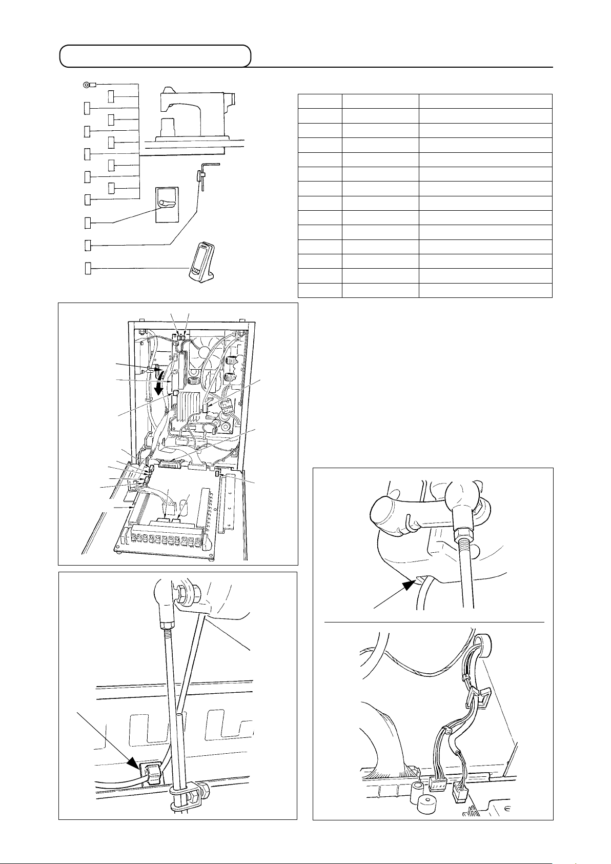
3-9 Connecting the cords
Ground wire
CN38
CN21
CN25
CN26
CN56
CN57
CN53
CN52
CN51
CN55
CN62
CN54
CN34
Cord inserting
port
PWR circuit
board
CN38
CN55
CN54
CN53
CN52
CN51
Auxiliary pedal
CN26
CN25
CN56
CN57
Sewing machine head
Knee SW
Operation panel
CN21
CN34
CN62
Terminal No. of poles Name of cable
CN38 W
CN21 W
CN25 R
CN26 R
CN56 W
CN57 W
CN53 W
CN52 W
CN51 W
CN55 1
CN62 Y
CN54 R
CN34 2
hite 4 poles Power cable of main motor
hite 9 poles Encoder cable of main motor
ed 2 poles Top feed fan cord
ed 2 poles Bottom feed fan cord
hite 10 poles Feed motor cord
hite 6 poles Auxiliary feed motor cord
hite 6 poles Head relay cord 1
hite 4 poles Head relay cord 2
hite 2 poles Presser lifter cord
0 poles DATA p.c.b. cord
ellow 4 poles
ed 4 poles
6 poles
1) Remove the auxiliary pedal cord and insert the
cord into the control box from the cord inserting
port. Pass the auxiliary pedal cord through the
rear side of the auxiliary pedal and insert it into
the control box from hole A located
on the lower
side of the pedal sensor.
2) Fix the auxiliary pedal cord with the sticker (small)
so that the cord does not move.
3) Connect CN38, 21, 25, and 26 to PWR p.c.b.
CN25 and 26 can be connected to either one.
Connect others to MAIN p.c.b.
MAIN circuit
board
Sticker (small)
A
–
–
8
Page 15
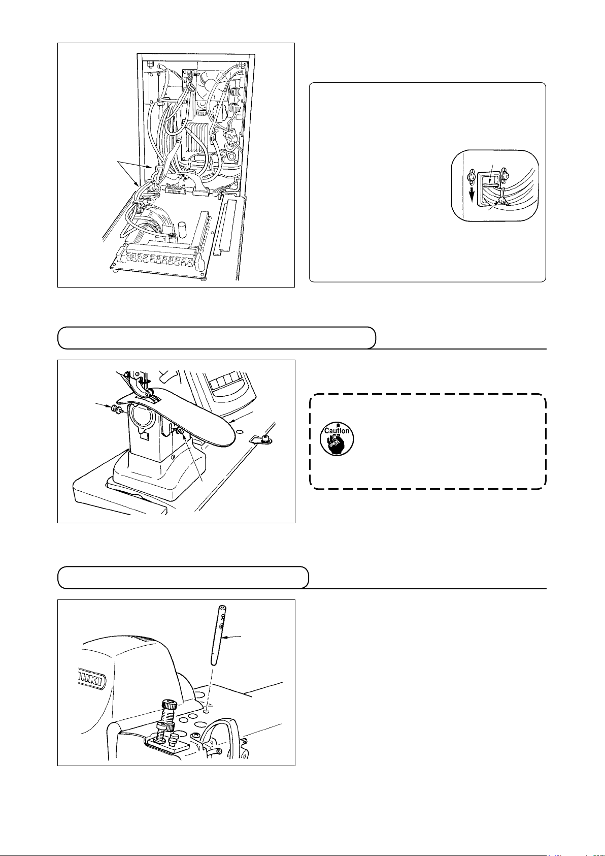
4) Fix the cords connected to MAIN p.c.b. with cord
clamp A.
Handling the cords
1) When xing the cords, connect them with the
sewing machine tilted, and bundle with clip
band 1.
Cord clamp A
2) When the machine head
is returned to its home
position, fix the cords
with cord xing plate 2
in the state that there is
the slack in the cords.
Caution : When tilting the sewing machine,
3-10 Installing the throat plate auxiliary plate
2
1
make sure that the head support
bar is attached to the table.
2
1
2
3-11 Installing the thread guide rod
1
Loosen two screws 2,
plate 1 and x it.
Adjust the height so that the top sur-
face of throat plate auxiliary plate
aligns with that of the throat plate.
If the height is not proper, material
ops and the feed amount is not set-
tled.
Securely
holes of it faces the front in the direction of the op-
erator.
insert thread guide rod 1 so
insert throat plate auxiliary
that two side
–
–
9
Page 16
3-12 Installing the thread stand
1) Assemble the thread stand unit and set it to the
hole located on the upper right side of the table.
2) Tighten lock nut 1 so that the thread stand unit
2
1
does not move.
3) When ceiling wiring is possible, pass the power
cable through the inside of thread stand rod 2.
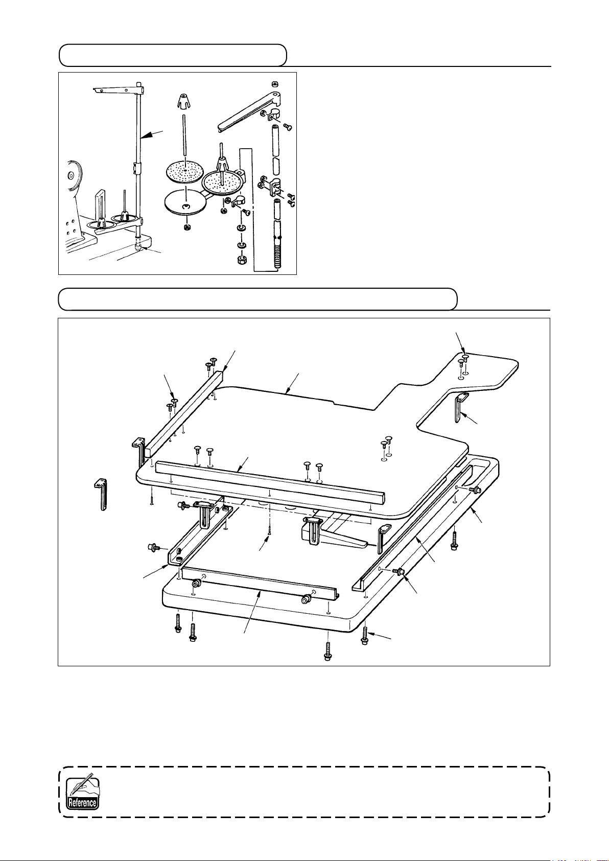
3-13 Assembling the table for work (WORK TOP TABLE)
3
8
6
9
6
1
4
2
Table
7
5
!1
!0
1) Install edge guide A 2 and B 3 on table for work 1 with 3 pcs. each of wood screw 7.
2)
Temporarily tighten base A 5 and base B 6 on the table with screws !0.
3) Temporarily tighten adjusting plate 4 with 8 screws 8 and 4 screws 9.
4) Place table for work 1 on the base and temporarily tighten it with screw !1.
5) Tighten screws 8, 9 and !0 while checking the whole position.
6) Loosen screw !1 and tighten it in accordance with the height you desire.
There are the standard size and the long one for the adjusting plate.
When you desire to make the table for work higher, replace the standard size plate with
the long size one.
–
–
10
Page 17
4. PREPARATION BEFORE OPERATION
4-1 Attaching the needle
WARNING :
Turn OFF the power before starting the work so as to prevent accidents caused by abrupt start of the
sewing machine.
1) Turn the handwheel until the needle bar reaches
the highest point of its stroke.
2) Loosen screw 2,
indented part Afacing exactly to the right in di-
D
B
1
2
C
A
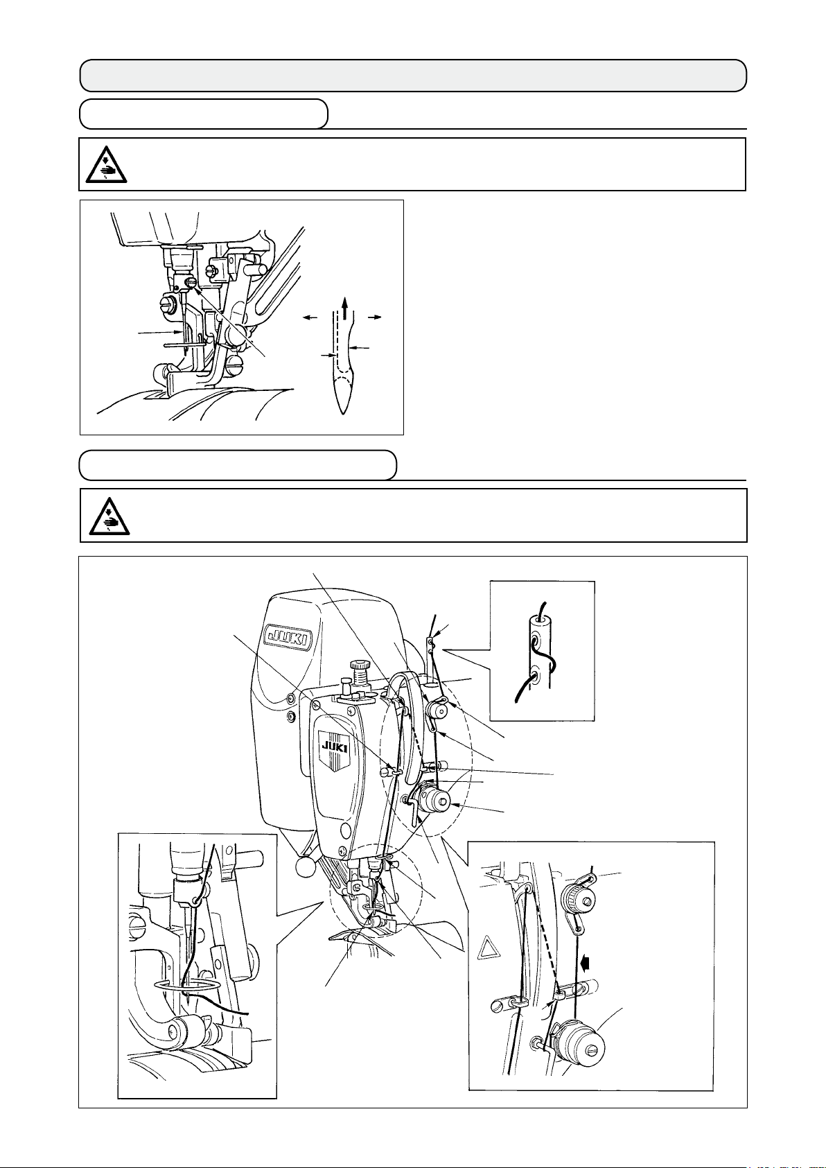
4-2 Threading the needle-thread
rection
3) Insert the needle fully into the hole in the needle
bar in the direction of the arrow until the end of
hole is reached.
4) Securely tighten screw 2.
5) Check that long groove C of the needle is facing
exactly to the left in direction D.
B.
and hold needle 1 with its
WARNING :
Turn OFF the power before starting the work so as to prevent accidents caused by abrupt start of the
sewing machine.
* Pass thread in
the order of 1
through
shown in the
illustration.
!3
as
!0
9
3
7
!1
1
6
2
4
8
5
!3
–
11
Note) Do not
!2
A
–
pass this
part to
section A.
Page 18
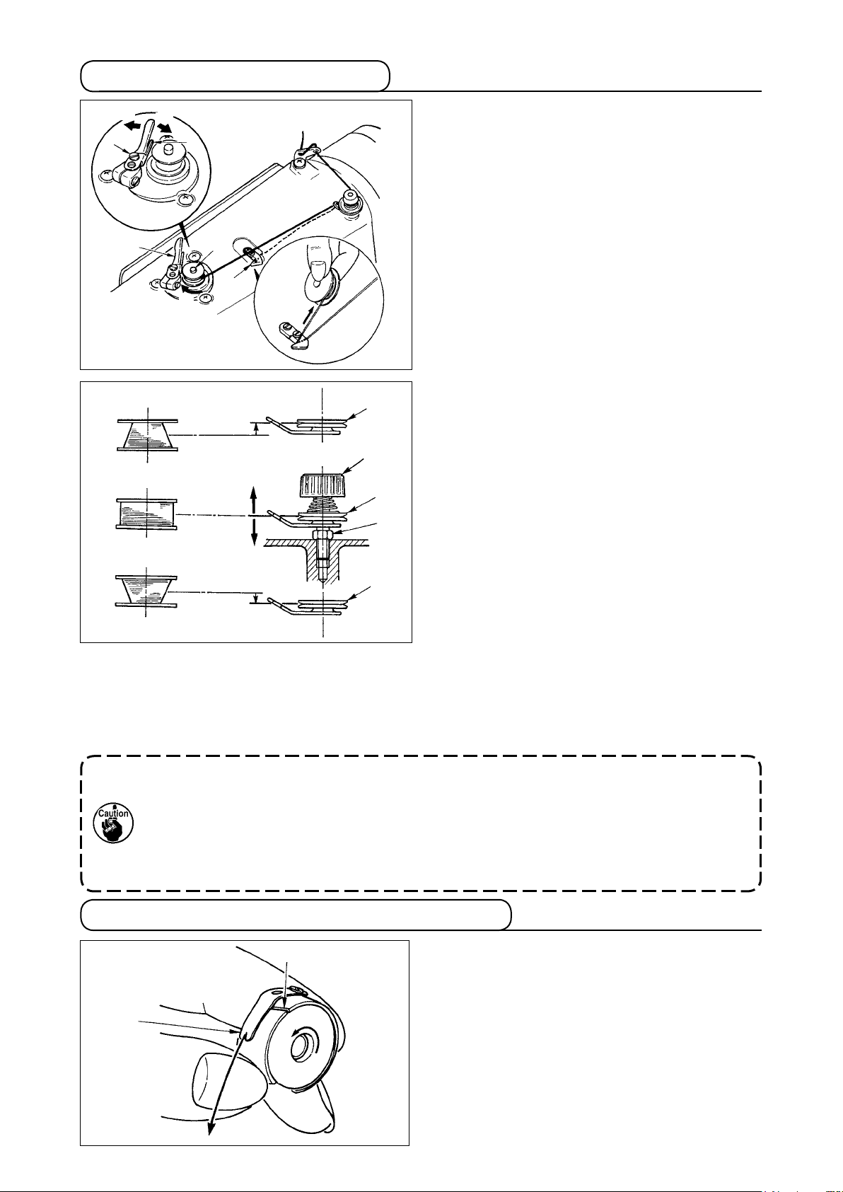
4-3 Winding the bobbin thread
B
A
4
2
• Move the position of the thread tension disk 7 to the direction of A as shown in the gure on the left
when the winding amount of the bobbin thread on the lower part of the bobbin is excessive and to the
direction of B as shown in the gure on the left when the winding amount of the bobbin thread on the
upper part of the bobbin is excessive.
After the adjustment, tighten the nut 6.
7) To adjust the tension of the bobbin winder, turn the thread tension nut 8.
5
1
3
C
7
8
A
7
6
B
7
1) Insert the bobbin deep into the bobbin winder
spindle 1 until it will go no further.
2) Pass the bobbin thread pulled out from the spool
rested on the right side of the thread stand fol-
lowing the order as shown in the gure on the
left. Then, wind clockwise the end of the bobbin
thread on the bobbin several times.
(In case of the aluminum bobbin, after winding
clockwise the end of the bobbin thread, wind
counterclockwise the thread coming from the
bobbin thread tension several times to wind the
bobbin thread with ease.)
3) Press the bobbin winder trip latch 2 in
tion
of A and
bin
rotates in the direction of C and
thread is wound up. The bobbin winder spindle
automatically as soon as the winding is fin-
1
ished.
4)
Remove the bobbin and cut the bobbin thread
with the thread cut retainer 3.
To adjust the winding amount o f the bobbin
5)
thread, loosen the setscrew 4 a
bobbin winder adjusting plate 5 to the direction
of A or B. Then, tighten the setscrew 4.
To the direction of A
To the direction of B : Increase
6) In case that the bobbin thread is not wound
evenly on the bobbin, loosen the nut 6 and
the bobbin thread tension to adjust the height of
the thread tension disk 7.
• It is the standard that the center of the bobbin is
as high as the center of the thread tension disk.
start the sewing machine. The bob-
nd move the
: Decrease
the direc-
the bobbin
turn
1. When winding the bobbin thread, start the winding in the state that the thread between the
bobbin and thread tension disk 7 is tense.
2.
3.
When winding the bobbin thread in the state that sewing is not performed, remove the needle
thread from the thread path of thread take-up and remove the bobbin from the hook.
There is the possibility that the thread pulled out from the thread stand is loosened due to
the inuence (direction) of the wind and may be entangled in the handwheel. Be careful of
the direction of the wind.
4-4 Setting the bobbin into the bobbin case
A
B
C
1) Install the bobbin in the bobbin case so that the
thread wound direction is clockwise.
2) Pa ss the t hread throug h thr ead slit A,
pull the thread in direction B. By so doing, the
thread will pass under the tension spring and
come out from notch B.
3) Check that the bobbin rotates in the direction of
the arrow when thread C is pulled.
–
–
12
and
Page 19
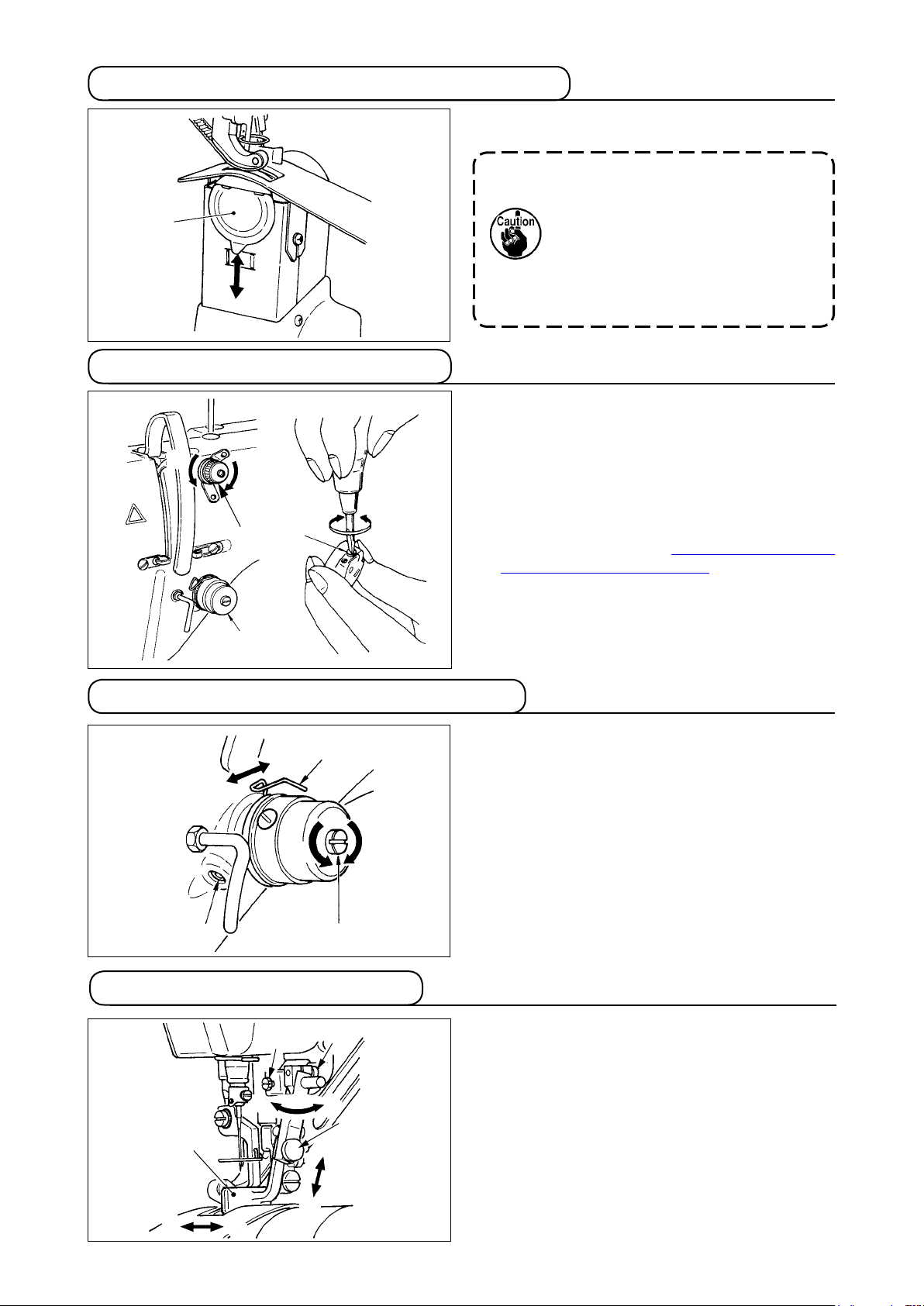
4-5 Attaching and removing the bobbin case
For attaching and removing the bobbin case, slide
cover1 up or down to perform it.
1
4-6 Adjusting the thread tension
[Adjusting the needle thread tension]
1)
Turn clockwise (direction A)
and the length of thread remaining at the needle
1
B
A
1
2
C
3
D
tip after thread trimming will be shortened.
2) Turn it counterclockwise (direction B)
length of thread will be lengthened.
3) Thread tension of thread tension No. 2 2 is set
with the operation panel.
For the details, refer to
needle thread tension" p. 31
[Adjusting the bobbin thread tension]
1)
Turn clockwise (direction C)
and the bobbin thread tension is increased.
2) Turn it counterclockwise (direction D)
tension is decreased.
1. When attaching the bobbin case, insert it until it will go no further. If it
is insufcient, the bobbin case may
fall off during sewing.
2. Be sur e to close the co ver w hen
starting the sewing machine.
There
is a danger of rolling cloth in
the bobbin case or the like.
thread tension nut No. 1
and the
"6-6 (3) Changing the
.
thread tension screw
and the
3
4-7 Adjusting the thread take-up spring
[ Changing the stroke amount of thread take-up spring
1) Loosen setscrew 2 in the thread tension base.
2) Turn clockwise (direction A)
3) Turn it counterclockwise (direction B) and the
[ When changing the pressure of thread take-up spring
1)
2) Turn clockwise (direction C)
2
1
A
B
D
C
3
4-8 Adjusting the stitch guide
2
C
1
A
B
3
D
4
E
F
1) When setscrew 2 is loosened, ne adjustment
2) When setscrew 3 is loosened, ne adjustment
3) When setscrew 4 is loosened, ne adjustment
]
1
the whole thread
tension and the stroke amount is increased.
stroke amount is decreased.
]
1
Put a thin screwdriver in the slot of thread tension rod
and turn it with screw 2 tightened.
3
the thread tension
rod and the pressure is increased and turn it
counterclockwise (direction D) and the pressure
is decreased.
B direction of stitch guide 1 position can be
-
A
performed. After the adjustment, securely tighten
setscrew 2.
and C - D direction of stitch guide 1 posi-
A - B
tion
can be performed. After the adjustment, se-
curely tighten setscrew 3.
direction of stitch guide 1 position can be
E - F
performed. After the adjustment, securely tighten
setscrew 4.
–
13
–
Page 20
5. HOW TO USE THE OPERATION PANEL
5-1. PREFACE1. PREFACE
1) Kind of sewing data handled with IP-420
Pattern name Description
Vector format data File that extension is ".VDT"
Read from media. Max. 99 patterns can be used.
Parameter data File that extension is ".EPD"
Read from media. Max. 99 patterns can be used.
2) To use the data for DP-2100 (VDT data and EPD data)
Insert a medium into the IP-420 and select pattern No. xxx from VDT data or EPD data.
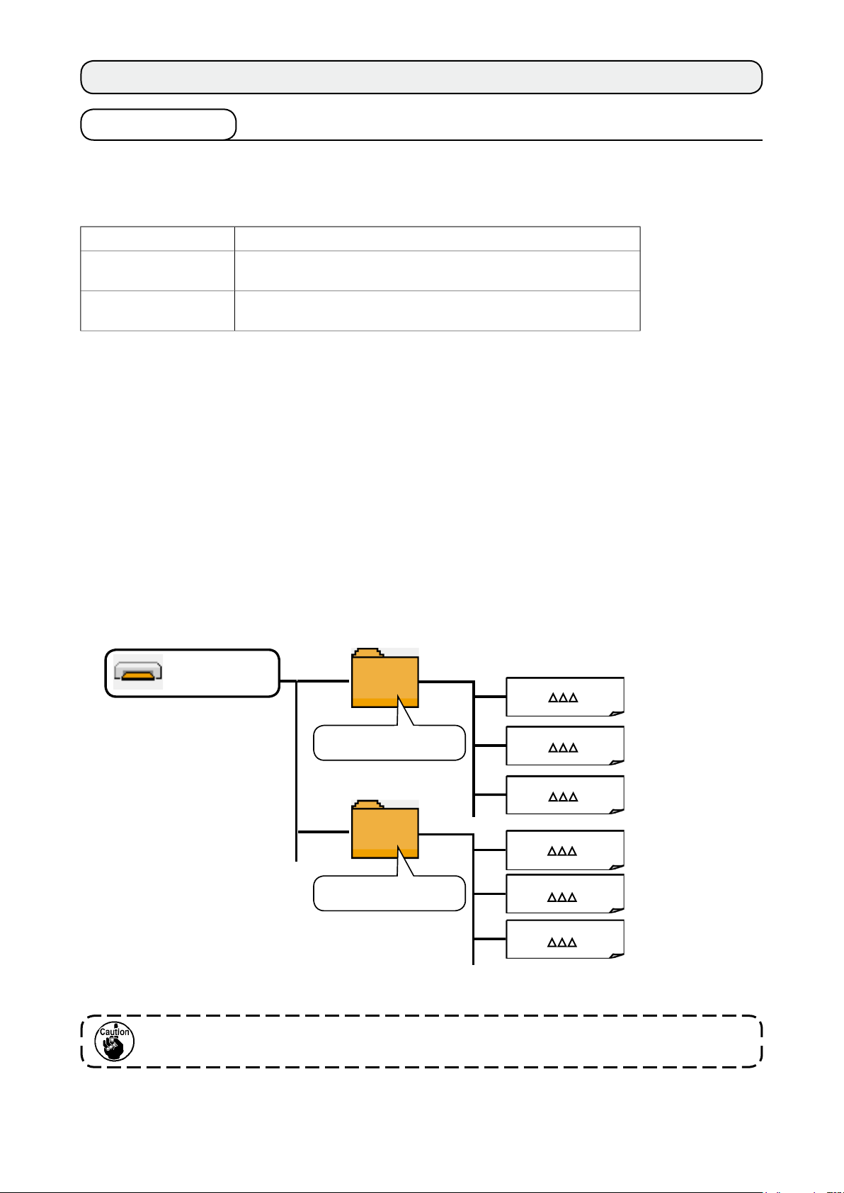
3) Folder structure of the media
Store each le in the directories below of the media.
Media drive
Store vector format data.
VDATA
DP2100
Stores parameter data
(exclusive for DP)
VD00
VD00 . VDT
VD00 . VDT
DP00 . EPD
DP00
DP00 . EPD
. VDT
. EPD
Vector format data:
Store in ¥VDATA.
Parameter data:
Store in ¥DP2100.
Data that are not stored in the directories above cannot be read. So, be careful.
–
–
14
Page 21
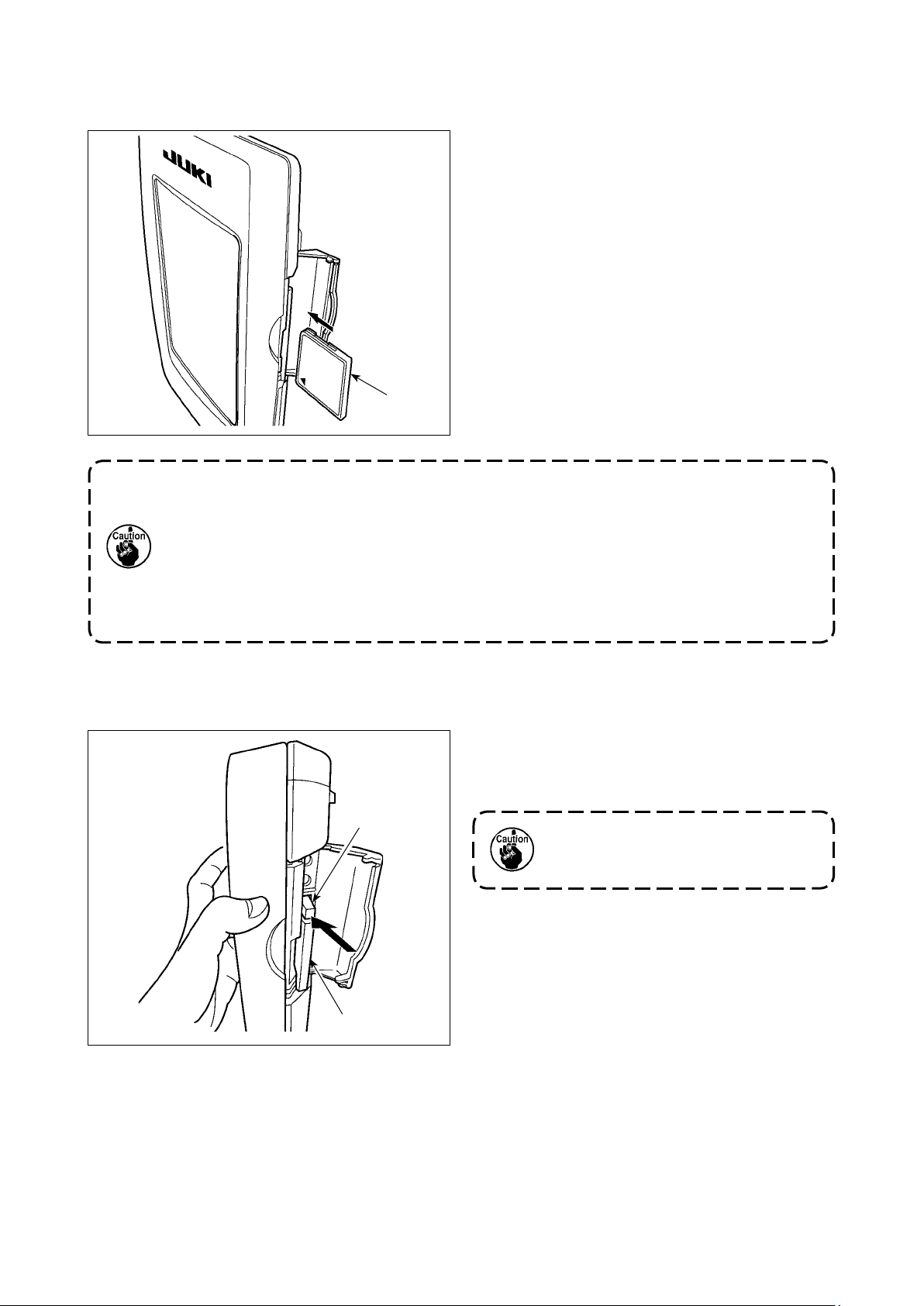
4) CompactFlash (TM)
Inserting the CompactFlash (TM)
■
1) Turn the label side of the CompactFlash(TM)
to this side (place the notch of the edge to the
rear.) and insert the part that has a small hole
into the panel.
2) After completion of setting of the media, close
the cover. By closing the cover, it is possible
to access. If the media and the cover come in
contact with each other and the cover is not
closed, check the following matters.
• Check that the media is securely pressed
until it goes no further.
Media
1. When the inserting direction is wrong, panel or media may be damaged.
2. Do not insert any item other than the CompactFlash (TM).
3. The media slot in the IP-420 accommodates to the CompactFlash (TM) of 2 GB or
less.
4.
The media slot in the IP-420 supports the FAT16 which is the format of the Compact-
Flash (TM). FAT32 is not supported.
5. Be sure to use the CompactFlash (TM) which is formatted with IP-420. For the formatting
procedure of the CompactFlash (TM), see "19. Performing formatting of the media", p.156.
• Check that the inserting direction of the me-
is proper.
dia
Removing the CompactFlash (TM)
■
2
1
1) Hold the panel by hand, open the cover, and
press the media 2
removing lever 1. The
media is eject.
When the lever 1 is strongly pressed,
the media 2 may be broken by pro-
truding and falling.
2) When the media 2
moving
is completed.
is drawn out as it is, re-
–
15
–
Page 22
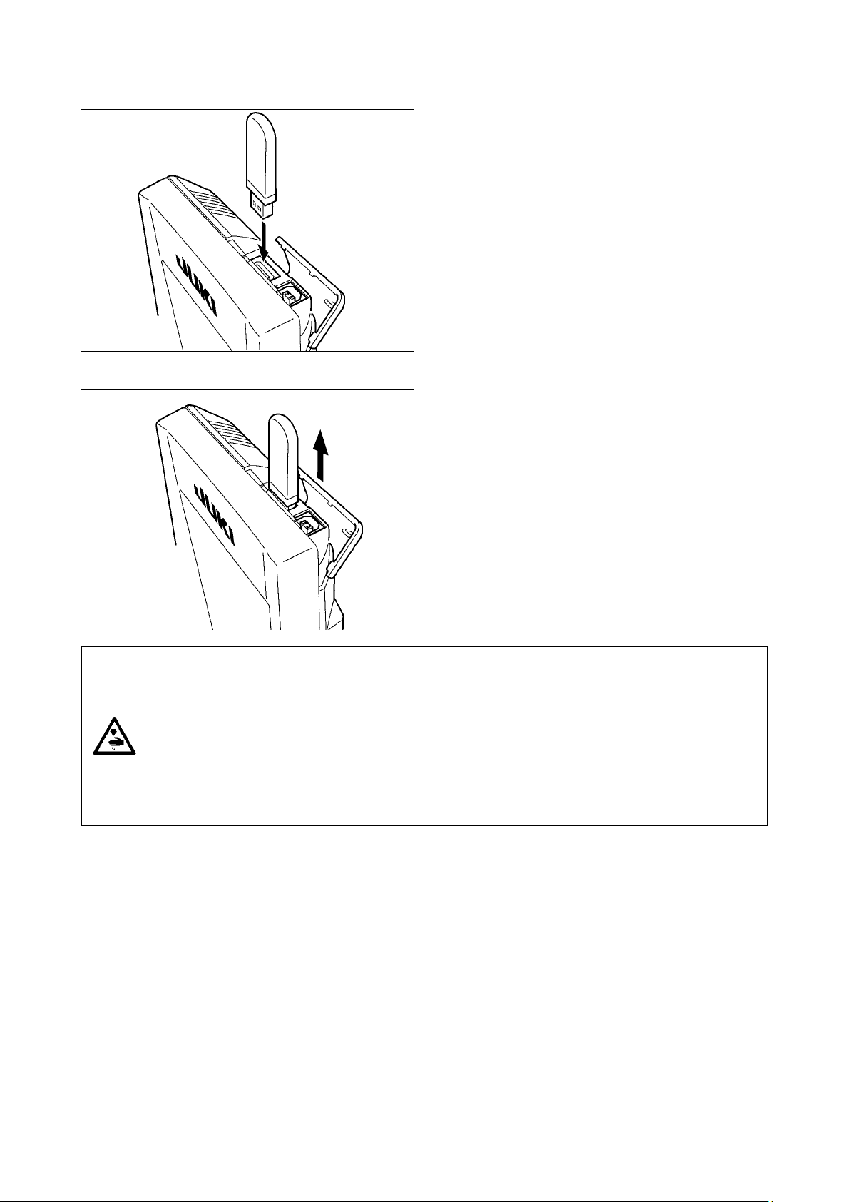
USB port
5)
Inserting a device into the USB port
■
Disconnecting a device from the USB port
■
the top cover and insert the USB device into
Slide
the USB port. Then, copy data to be used from the
USB device onto the main body.
After completion of copying the data, remove the
USB device.
Remove the USB device. Put the cover back in
place.
CAUTION :
Cautions when using the media
• Do not wet or touch it with wet hands. Fire or electric shock will be caused.
• Do not bend, or apply strong force or shock to it.
• Never perform disassembling or remodeling of it.
• Do not put the metal to the contact part of it. Data may be disappeared.
• Avoid storing or using it in the places below.
Place of high temperature or humidity / Place of dew condensation /
Place with much dust / Place where static electricity or electrical noise is likely to occur
–
16
–
Page 23

Precautions to be taken when handling USB devices
1
• Do not leave the USB device or USB cable connected to the USB port while the sewing machine is in opera-
tion.
The machine vibration can damage the port section resulting in loss of data stored on the USB device or
breakage of the USB device or sewing machine.
• Do not insert/remove a USB device during reading/writing a program or sewing data.
It may cause data breakage or malfunction.
• When the storage space of a USB device is partitioned, only one partition is accessible.
• Some type of the USB device may not be properly recognized by this sewing machine.
• JUKI does not compensate for loss of data stored on the USB device caused by using it with this sewing ma-
chine.
• When the panel displays the communication screen or pattern data list, the USB drive is not recognized even
if you insert a medium into the slot.
• For USB devices and media such as CF cards, only one device/medium should be basically connected/in-
serted to/into the sewing machine. When two or more devices/media are connected/inserted, the machine will
only recognize one of them. Refer to the USB specications.
• Insert the USB connector into the USB terminal on the IP panel until it will go no further.
•
Do not turn the power OFF while the data on the USB ash drive is being accessed.
USB specications
2
• Conform to USB 1.1 standard
• Applicable devices *
1 ____
Storage devices such as USB memory, USB hub, FDD and card reader
• Not-applicable devices __ CD drive, DVD drive, MO drive, tape drive, etc.
• Format supported _____FD (oppy disk) FAT 12
Others (USB memory, etc.), FAT 12, FAT 16, FAT 32
• Applicable medium size _FD (oppy disk) 1.44MB, 720kB
Others (USB memory, etc.), 4.1MB ~ (2TB)
• Recognition of drives __For external devices such as a USB device, the device which is recognized rst
is accessed. However, when a medium is connected to the built-in media slot, the
access to that medium will be given the highest priority. (Example: If a medium is in-
serted into the media slot even when the USB memory has already been connected
to the USB port, the medium will be accessed.)
• Restriction on connection
_
Max. 10 devices (When the number of storage devices connected to the sewing
machine has exceeded the maximum number, the 11th storage device and beyond
will not be recognized unless they are once disconnected and re-connected. )
• Consumption current ___The rated consumption current of the applicable USB devices is 500 mA at the maxi-
mum.
1
: JUKI does not guarantee operation of all applicable devices. Some device may not operate due to a compat-
*
ibility problem.
–
–
17
Page 24
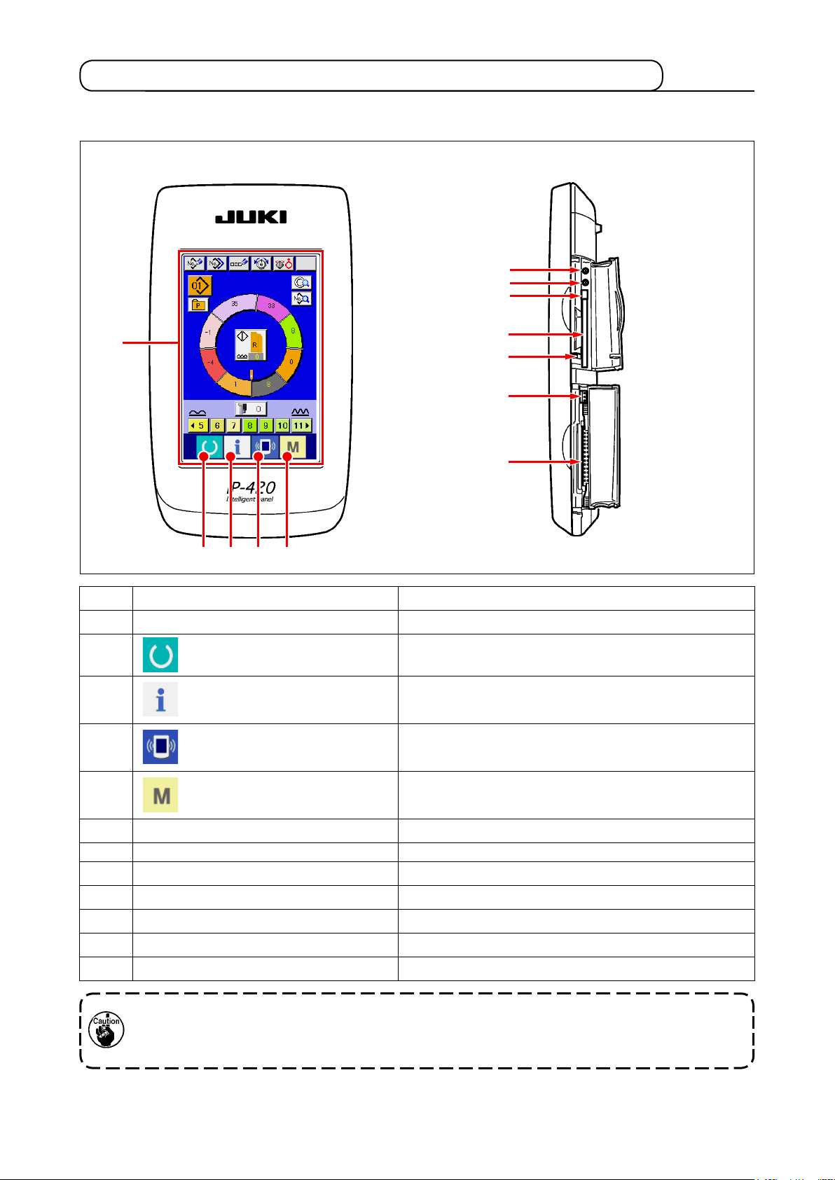
5-2. BASIC OPERATION OF THE OPERATION PANEL (IP-420)
(1) Conguration of IP-420
[ Front ] [ Right side ]
6
7
8
1
Symbol
1
2
3
4
2 3 4 5
Name
OUCH PANEL, LCD display section
T
READY key
INFORMATION key
COMMUNICATION key
9
!0
!1
!2
Description
Change-over of the data input screen and the sewing screen is
performed.
Change-over of the data input screen and the information screen is
performed.
Change-over of the data input screen and the communication
screen is performed.
5
Contrast
6
Brightness
7
CompactFlash
8
CompactFlash
9
Cover detection switch
!0
Connector
!1
Connector
!2
MODE CHANGEOVER key
control
control
(TM) eject button
(TM) slot
for external switch
for control-box connection
Change-over of the data input screen and the mode change-over
screen which performs various details setting.
Lightly press the target key on the touch panel with a ngertip to operate the IP-420. If you
operate with any means other than your ngertip, the IP-420 can malfunction or the glass
surface of the touch panel can be scratched or break.
–
–
18
Page 25

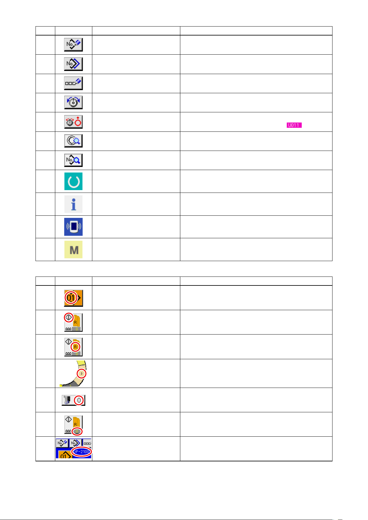
(2) Buttons used in common
Buttons that perform common operation in the respective screens of IP-420 are as described below.
Symbol
Name
CANCEL button
ENTER button Data changed are determined.
UP SCROLL button This button scrolls button or display upward.
DOWN SCROLL button This button scrolls button or display downward.
RESET button This button releases error and the like.
NUMERAL INPUT button Ten keys are displayed and input of number can be performed.
CHARACTER INPUT button Character input screen is displayed.
Pop-up screen is closed. In case of the data change scree n, the data during
changing can be cancelled.
Description
–
19
–
Page 26
6.
OPERATION OF THE SEWING MACHINE (SEMI-AUTOMATIC BASIC VOLUME)
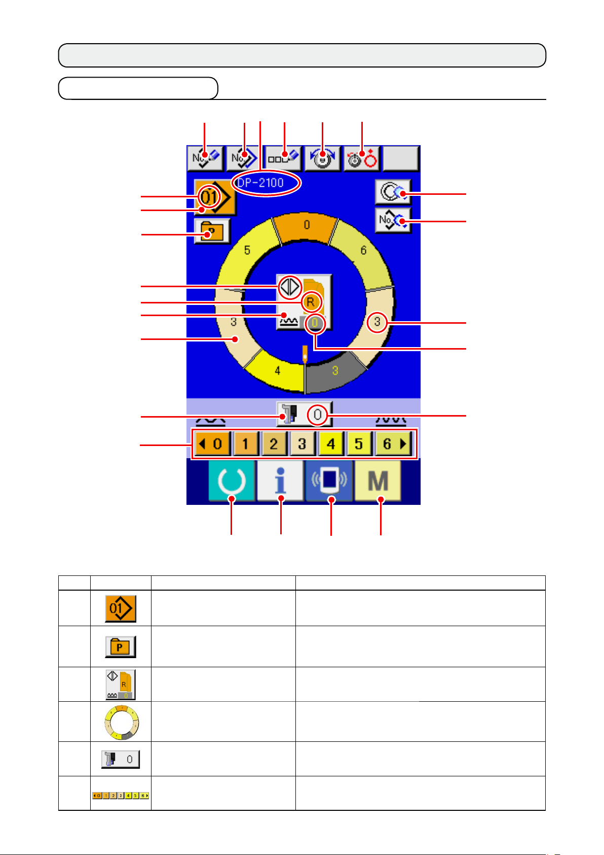
6-1 Data input screen
A
1
2
B
C
3
4
7
8 9
!0
!1G
!2
!3
D
F
5
6
!4
No. Button Name of button Description
1
2
3
4
PATTERN SELECTION button Pattern No. being selected at present is displayed on the
DIRECT SELECTION button When the button is pressed, the list screen of pattern
LEFT/RIGHT/ALTERNATE
SEWING SELECTION button
STEP SELECTION button When the button is pressed, the step becomes in the
!5
!6
button and when the button is pressed, PATTERN No.
CHANGE screen is displayed.
Nos. which are registered in DIRECT SELECTION button
is displayed.
Changeover method of program (for right sleeve and left
sleeve) during sewing is selected.
state of selection.
!7
E
5
6
SHIRRING AMOUNT FOR
AUXILIARY FEED button
SHIRRING AMOUNT button When the button is pressed, shirring amount of the step
When the button is pressed, shirring amount for auxiliary
feed change screen is displayed.
being selected is changed.
–
–
20
Page 27
No. Button Name of button Description
7
PATTERN NEW REGISTER
button
When the button is pressed, pattern No. new register
screen is displayed.
8
9
!0
!1
!2
!3
!4
!5
!6
PATTERN COPY button When the button is pressed, sewing data copy screen is
displayed.
LETTER INPUT button When the button is pressed, letter input screen is dis-
played.
NEEDLE THREAD TENSION
SETTING button
DISK RISE button When the button is pressed, thread tension disk No. 1
STEP DETAILS button When the button is pressed, list of sewing data corre-
SEWING DATA DISPLAY but-
ton
READY key Changeover of data input screen and sewing screen is
INFORMATION key Changeover of data input screen and information screen
COMMUNICATION key Changeover of data input screen and communication
When the button is pressed, needle thread tension
change screen is displayed.
rises. (Turn OFF the base tension during waiting.)
sponding to the step being selected is displayed.
List of sewing data corresponding to the pattern No. be-
ing selected is displayed.
performed.
is performed.
screen is performed.
!7
SymbolDisplay Name of display Description
A
B
C
D
E
F
G
MODE key Changeover of data input screen and mode changeover
screen to perform various details setting is performed.
PATTERN No. display Pattern No. is displayed.
ALTERNATE SEWING display This is displayed when alternate sewing is selected.
LEFT/RIGHT SLEEVE display R display : Program for right sleeve is called.
L display : Program for left sleeve is called.
SHIRRING AMOUNT display Shirring amount is displayed.
SHIRRING AMOUNT FOR
AUXILIARY FEED display
SHIRRING AMOUNT INCREASE/DECREASE SET
VALUE display
PATTERN NAME display Pattern name is displayed.
Shirring amount of auxiliary feed is displayed.
Shirring amount increase/decrease set value is displayed.
–
21
–
Page 28
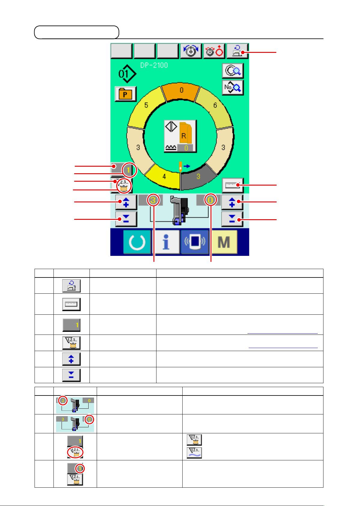
6-2 Sewing screen
@0
K
@1
J
!8
!9
@2
@3
H
No. Button Name of button Description
!8
!9
@0
@1
@2
@3
Max. SEWING SPEED
SETTING button
MEASURE button
COUNTER SETTING
button
COUNTER SELECTION button
+ button
– button
When the button is pressed, max. sewing speed setting screen is displayed.
When the button is pressed, length of each step is measured during
sewing and is reected to icon display shape of step selection button.
When the button is pressed, bobbin/No. of pcs. counter setting screen is
displayed.
T
his screen is displayed when setting at
When the button is pressed, bobbin/No. of pcs. counter is changed over.
This screen is displayed when setting at
When the button is pressed, the numeral is increased.
When the button is pressed, the numeral is decreased.
I
"12. USING COUNTER" p. 110.
"12. USING COUNTER" p. 110.
@2
@3
Symbo
H
I
J
K
l
Display Name of display Description
SHIRRING AMOUNT display Shirring amount is displayed.
SHIRRING AMOUNT FOR
COUNTER display
AUXILIARY FEED display
COUNTER SET VALUE display Counter set value is displayed.
Shirring amount of auxiliary feed is displayed.
display :
This is displayed when bobbin counter is used.
display : This is displayed when No. of pcs. counter is used.
–
–
22
Page 29
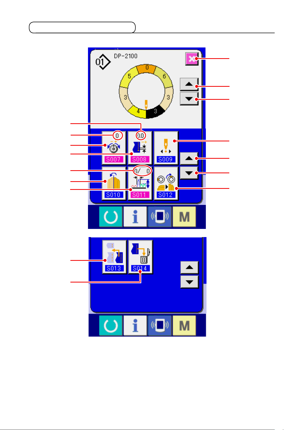
6-3 Details data input screen
M
L
@7
@2
@3
@4
@9
@8
N
#0
#1
#3
#4
@5
@6
#2
–
23
–
Page 30
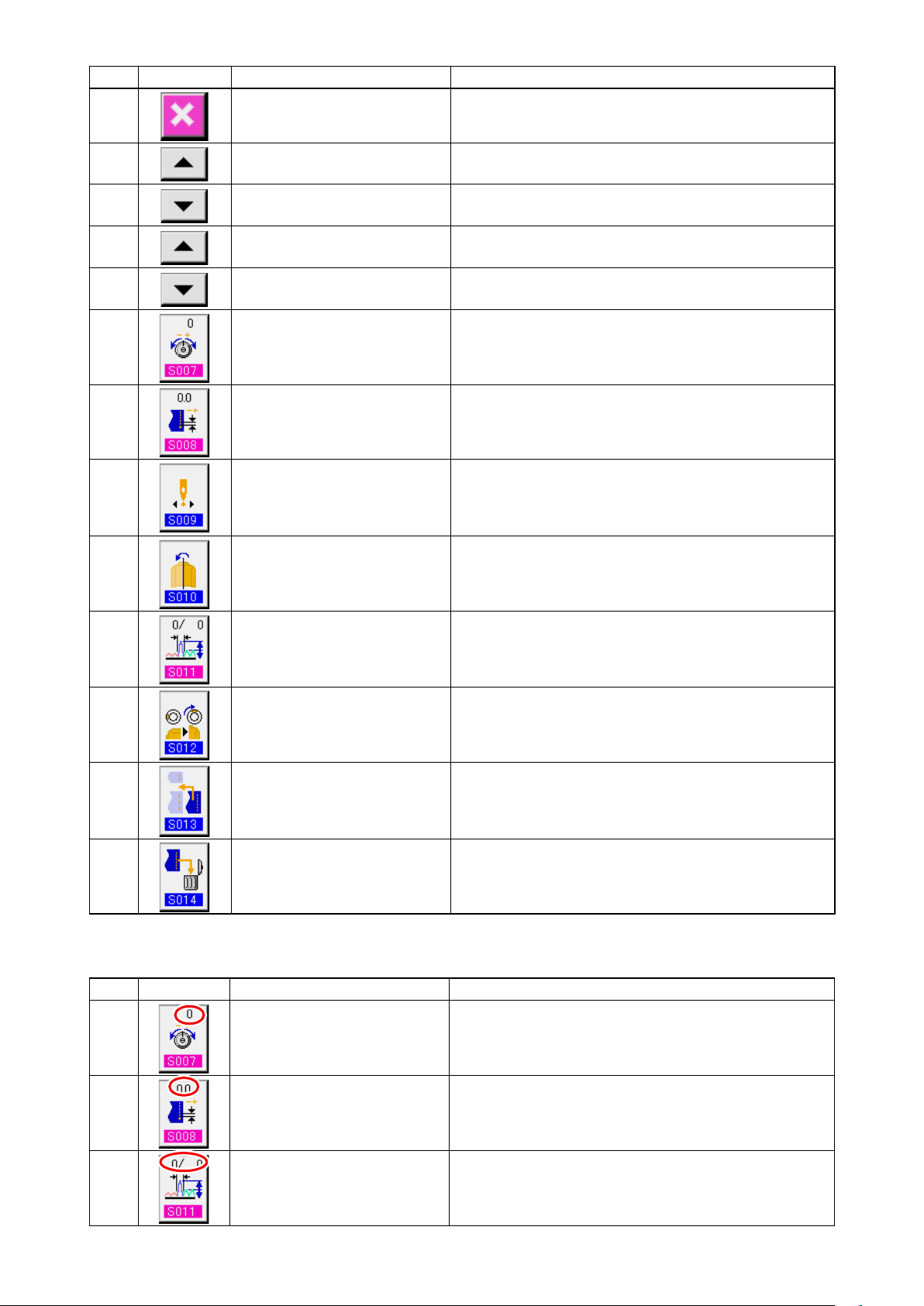
No. Button Name of button Description
@2
CANCEL button When the button is pressed, the step details button is
closed.
@3
@4
@5
@6
@7
@8
@9
#0
STEP FEED button When the button is pressed, the selected step advances
by one.
STEP RETURN button When the button is pressed, the selected step returns by
one.
DETAILS SELECTION
SCREEN FEED button
DETAILS SELECTION
SCREEN RETURN button
COMPENSATION THREAD
TENSION SETTING button
COMPENSATION PITCH SET-
TING button
START POSITION CHANGE
button
MIRRORING button AMOUNT When the button is pressed, mirroring screen is displayed.
When the button is pressed, the details selection screen
scrolls forward.
When the button is pressed, the details selection screen
scrolls backward
When the button is pressed, pattern deletion screen is
displayed.
When the button is pressed, compensation thread tension
setting screen is displayed.
When the button is pressed, mirroring screen is displayed.
is displayed.
#1
#2
#3
#4
SymbolDisplay Name of display Description
L
COMPENSATION SHIRRING
AMOUNT button
TOP NOTCH POSITION
CHANGE button
STEP ADDITION button When the button is pressed, step addition setting screen
STEP DELETION button When the button is pressed, step deletion screen is dis-
COMPENSATION THREAD
TENSION display
When the button is pressed, compensation shirring
amount setting screen is displayed.
When the button is pressed, top notch position change
screen is displayed.
is displayed.
played.
Set value of compensation thread tension is displayed.
M
N
COMPENSATION PITCH
display
COMPENSATION AMOUNT
display
S
et value of compensation pitch is displayed.
Set value of compensation shirring amount is displayed.
–
–
24
Page 31

6-4 Feed amount
The explanation is given for the feed amount of the sewing machine.
Feed amount on the operation consists of the three
kinds of feed amounts, bottom feed amount (pitch),
main feed amount (pitch + shirring amount) and aux-
iliary
feed amount (pitch + shirring amount + shirring
amount for auxiliary feed).
3
2
1
A
In case of A,
tom feed belt 1 m
sewing machine (1 stitch).
In case of B, when shirring amount is set to 3, main
feed belt 2 moves 2.3 mm per rotation of the sewing
machine ( 1 stitch).
This means that set value “1” of shirring amount (main
feed) is in steps of 0.1 mm and when the set value
is converted to mm, 3 x 0.1 = 0.3 mm is calculated.
This value is added to pitch (bottom feed) and the
total value becomes the moving amount of the main
feed belt.
Main feed amount = pitch + shirring amount
when pitch (
oves 2.0 mm per rotation of the
2.3 mm = 2.0 mm + 0.3 mm
) is set to 2.0, bot-
Pitch setting screen
B C
Sewing screen
In case of
is set to 2, auxiliary feed belt 3 moves 2.5 mm per
rotation of the sewing machine (1 stitch).
This means that set value “1” of shirring amount for
auxiliary feed (auxiliary feed) is in steps of 0.1 mm
and when the set value is converted to mm, 2 x 0.1 =
0.2 mm is calculated. This value is added to the main
feed amount and the total value becomes the moving
amount of the auxiliary belt.
Auxiliary feed amount = main feed amount +
–
–
25
when shirring amount for auxiliary feed
,
C
shirring amount for
auxiliary feed
2.5 mm = 2.3 mm + 0.2 mm
Page 32

6-5 Basic operation of the sewing machine
(1) Prepare the materials.
Prepare right and left sleeves and garment body.
(2) Turn ON the power switch
When the power is turned ON first, the language
selection screen is displayed. Set the language you
use. (It is possible to change with Memory switch
.)
When ending the selection screen
Auto-lifter does not work until the screen moves to the sewing screen or the new creation
screen. After it has worked, it works in all screens. So, be careful.
(3) Calling the pattern <Pattern No. selection>
Two programs (for right sleeve and left sleeve) are
entered in one pattern. Further, the respective pro-
1
grams consist of single or plural steps (sewing data
between the respective notches are stored).
with CANCEL button
button without performing the
language selection, the language se-
lection screen is displayed whenever
the power is turned ON.
or ENTER
1) Press PATTERN SELECTION button 1.
–
–
26
Page 33

2
2) Press U P /DOWN S C R O LL b u t t ons
2 to dis p lay pat t er n No . bu t t on
of the pattern you desire to
call.
3) Press pattern No. button
4) Press ENTER button
4
3
4
.
(4) Select left/right alternate sewing. <Left/right alternate sewing selection>
Press LEFT/RIGHT ALTERNATE SEWING button
3.
5
to select the program changeover method
5
(for right sleeve and left sleeve).
Alternate sewing, right : Left/right alternate
–
27
–
sewing starting from the right sleeve
Alternate sewing, left : Left/right alternate
sewing starting from the left sleeve
Right sleeve only : Right sleeve sewing
only
Left sleeve only : Left sleeve sewing only
Page 34

(5) Perform sewing.
6
1) Press READY key 6.
2) Display is changed over from data input screen
to sewing screen B.
A
A
B
3)
Set sleeves and garment body to the sewing
machine.
* When temporarily setting the shirring amount to
"0" during sewing, press SHIRRING RELEASE
switch C.
When the switch is pressed, LED lights up
C
and the shirring amount is set to "0". When the
switch is pressed twice, LED goes off and the
shirring amount returns to the shirring amount of
the selected step.
–
28
–
Page 35

4) Check LEFT/RIGHT ALTERNATE SEWING but-
7
1
ton
whether or not the set materials
1
correspond with the called program (for right
sleeve/left sleeve).
5) Start sewing.
6) When sewing is performed up to the next notch,
stop the sewing machine once.
7) Press once knee switch 7.
Step of the program
advances by one (A).
8
8) Repeat procedure 5) through 7) until the end of
sewing.
A
9)
Perform thread trimming with pedal 8.
–
29
–
Page 36

6-6 Basic change of the set value
(1) Changing the sewing speed <Max. sewing speed setting>
1
1) Press MAX. SEWING SPEED SETTING button
1in the sewing screen.
2) Press MAX. SEWING SPEED CHANGE button
(fast) and
A
change "speed set value" A
(slow) 2 alternately to
.
2
(2) Changing the pitch <Pitch setting>
3
1
3) Press ENTER button
1) Press SEWING DATA DISPLAY button
3.
.
1
–
30
–
Page 37

2) Pr e s s "+"/ "– " bu t t on s 2 t
o
change "sewing pitch" A.
3) Press ENTER button
3.
A
2
3
(3) Changing the needle thread tension <Needle thread tension setting>
1) Press NEEDLE THREAD TENSION SETTING
1
button 1.
2
▼▲
2) Change "needle thread tension set value" A by
pressing numeric keys
buttons
3
(
3) Press ENTER button
4
to
).
5.
or
2
A
5
3
4
–
–
31
Page 38

(4) Changing the shirring amount <Shirring amount setting>
1) Press STEP SELECTION button
to select step.
1
1
A
2
2) Pr e s s "+"/ "– " bu t t on s
change shirring amount set value A.
2 t
o
(5) Changing the shirring amount of auxiliary feed
Press STEP SELECTION button
1)
1
to select step.
1
2) Pr e s s "+"/ "– " bu t t on s
change shirring amount set value for auxiliary
A
2
feed A.
<Auxiliary feed shirring amount setting>
2 to
–
32
–
Page 39

6-7 Creating the pattern <Pattern creation>
The way of correcting the sample pattern and creating the pattern with ease is explained in the basic volume.
1) Prepare the materials.
2) Turn ON the power.
3) Call a sample pattern where the sewing products
and number of steps are the same.
Refer to
4) Change the pitch.
Refer to
5) Select left/right alternate sewing.
Refer to
sewing" p. 27
"6-5 (3) Calling the pattern" p. 26
"6-6 (2) Changing the pitch" p. 30
"6-5 (4) Select left/right alternate
.
.
.
1
2
Press READY key
6)
7) Perform sewing.
8) Stop the sewing machine at each notch and
perform checking of shirring amount.
9) When notches do not t properly, press "+"/ "–"
buttons
on the way to change shirring amount set value A.
Then perform re-sewing.
Refer to
amount" p. 32
10)
When the sleeve material on the outlet seam
side delays, press "+"/ "–" buttons
3
3
A
B
set value of shirring amount for auxiliary feed B.
Then perform re-sewing.
Refer to
amount of auxiliary feed" p. 32
11) When the program for one sleeve is completed,
sew the other sleeve and correct the program.
"6-6 (4) Changing the shirring
.
after thread trimming on the way to change
"6-6 (5) Changing the shirring
1.
after thread trimming
2
.
–
33
–
Page 40

6-8 Deleting the pattern <Pattern deletion>
1) Press PATTERN SELECTION button 1.
1
3
2
2) Press UP/DOWN SCROLL buttons
to display pattern No. button
of the pattern to be deleted.
3
3) Press PATTERN No. button
.
3
4)
Press PATTERN DELETION button
2
4.
3
4
–
34
When deleting it, the pattern does not
return to the former one. So, be careful.
–
Page 41

5
5) Press ENTER button 5.
6
6) Press CANCEL button 6.
–
35
–
Page 42

7.
OPERATION OF THE SEWING MACHINE (SEMI-AUTOMATIC APPLICATION VOLUME)
7-1 Correcting the pattern
(1)
Changing the needle thread tension of specied step <Compensation thread tension setting>
* This is the function to add the needle thread ten-
2
1
sion of the specied step to the overall needle
thread tension as much as "compensation nee-
dle thread tension set value".
3
1) Press STEP SELECTION button
to select the step.
1
2) Press STEP DETAILS button 2.
3) Press COMPENSATION THREAD TENSION
button
3.
4) Change "compensation thread tension set value"
pressing numeric keys
by
A
buttons
▼▲
When inputting the minus numeral in
the ten key pop-up screen, press the
minus button after inputting "0" and
A
4
Press ENTER button
5)
7
5
6
–
36
–
input the numeral.
(
5
to 4 or
).
6
7.
Page 43

6
6) Press CANCEL button 6.
(2) Changing the pitch of specied step <Compensation pitch setting>
* The state that is possible to change the step on the sewing screen is the state that step 1 is selected
before starting sewing.
* This is the function to add the pitch of the specied step to the overall pitch as much as the compensa-
tion pitch set value.
1
2
1) Press STEP DETAILS button
state that step 1 is selected.
2) Press STE P F EED /RETURN butto ns
to select the step to be changed.
2
1 i
n the
3
3) Press COMPENSATION PITCH button
–
–
37
3.
Page 44

4) Change "compensation pitch set value" A b
y
pressing numeric keys
buttons
When inputting the minus numeral in
the ten key pop-up screen, press the
minus button after inputting "0" and
A
4
Press ENTER button
5)
7
5
6
8
6) Press CANCEL button
input the numeral.
(
5
to 4 or
).
6
7.
8.
▼▲
(3) Increasing/decreasing the shirring amount of all steps
<Shirring amount increase/decrease setting>
1) Press SEWING DATA DISPLAY button 1.
1
–
–
38
Page 45

2) P r e ss "+ " / "– " button s
change shirring amount increase/decrease set
value A.
Press ENTER button 3.
3)
A
2
3
2
t o
(4) Increasing/decreasing the shirring amount immediately after changeover of step
<Compensation shirring amount setting>
2
1
1) Press STEP SELECTION button
to select the step.
1
2) Press STEP DETAILS button
3) Press COMPENSATION SHIRRING AMOUNT
button
3.
2.
3
–
39
–
Page 46

B
A
4 4
5
4) Press " + " / " – " bu t t ons
4 t
change compensation shirring amount set value
and
number of stitches of compensation shirr-
A
ing
amount B.
B
Shirring amount
A
6
3
o
6
1
Compensation shirring amount is the shirring
¡
2
3
4
amount to add to the shirring amount of the step
after changeover at the time of step changeover.
Number of stitches of shirring amount compen-
¡
sation is the number of stitches of the section
of number of stitches to add the compensation
shirring amount from the step changeover.
5) Press ENTER button 5.
6) Press CANCEL button 6.
Step
(5) Adding the step <Step addition>
1
3
2
A
1) Press READY key 1 to change over the
screen to data input screen
Press STEP SELECTION button
2)
to select the step which is one before the step
2
.
A
addition position.
3) Press STEP DETAILS button
–
–
40
3
.
Page 47

4
4) Press DOWN SCROLL button
4.
5) Press STEP ADDITION button 5.
5
6)
Press ENTER button
6.
6
–
41
–
Page 48

7
6
7 ) P r e s s S H I R R I N G A M O U N T b u t t o n s
o ch a n ge sh i r ring
7 t
amount set value A.
8)
Press ENTER button 6.
A
(6) Deleting the step <Step deletion>
8
3
9)
Press CANCEL button
1) Press READY key
screen to data input screen A.
8.
to change over the
1
1
2
A
2)
Press STEP SELECTION button
to select the step to be deleted.
2
3) Press STEP DETAILS button
–
–
42
3
.
Page 49

4
4) Press DOWN SCROLL button
4.
5) Press STEP DELETION button 5.
5
6) Press ENTER button
6.
6
–
43
–
Page 50

7
7) Press CANCEL button 7.
(7) Changing the start position of program <Start position change>
1
3
2
A
1) Press READY key 1
screen to data input screen
Press STEP SELECTION button
2)
to select the step which is the start position
2
you desire.
3) Press STEP DETAILS button
4) Press START POSITION CHANGE button
.
4
to change over the
.
A
3.
4
–
44
–
Page 51

5
5) Press ENTER button 5.
6
6) Press CANCEL button 6.
–
45
–
Page 52

(8) Mirroring the program of one sleeve and creating the program of the other sleeve
<Mirroring function>
1
2
A
1) Press READY key
screen to data input screen A.
Press STEP DETAILS button 2.
2)
3) Press MIRRORING button
to change over the
1
3.
3
4
4) Press ENTER button
4.
–
46
–
Page 53

5
5) Press CANCEL button 5.
(9) Changing the top notch position of program <Top notch position change>
1
3
2
A
1) Press READY key
screen to data input screen
Press STEP SELECTION button
2)
select the step which is the top notch posi-
to
2
tion
you desire.
3) Press STEP DETAILS button 3.
4) Press TOP NOTCH POSITION CHANGE button
4.
to change over the
1
.
A
4
–
47
–
Page 54

5
5) Press ENTER button
5.
6
6) Press CANCEL button 6.
–
48
–
Page 55

(10) Naming the pattern <Data name setting>
2
1
B
A
6
1) Press READY key
screen to data input screen A.
Press LETTER INPUT button
2)
3) It is possible to input the character by pressing
CHARACTER button 3 you desire to input. As
many as 14 characters of characters (
1 to change over the
2.
to
4
3
5
and to ) and symbols ( , ,
, , and ) can be inputted (B).
Cursor can be move d w ith CURSOR LEFT
MOVE bu t t o n
MOVE but ton
erase the inputted character adjust the cursor to
the position of the character you desire to erase
and press ERASE button
4) Press ENTER button
C
5) Inputted letters are displayed in the pattern
name display section C.
a n d C U R S OR RI G H T
4. Whe n y ou desire t o
5.
6.
–
49
–
Page 56

7-2 Copying the pattern <Pattern copy>
(1) Pattern copy in semi-automatic mode <Copy to semi-automatic>
2
1) Press READY key 1 to change over the
screen to data input screen A.
2)
Press PATTERN COPY button 2.
A
1
3
4
3) Press PATTERN No. button
to select the pattern of copy source.
3
4) Press COPY DESTINATION INPUT button
.
4
5) Input the pattern No. of copy destination with ten
keys
the pattern No. which has not been used yet with
▼▲
to 5. It is possible to retrieve
buttons (
6 and 7 ).6)
6
7
5
8
–
50
Press ENTER button
–
8.
Page 57

9
7) Press CANCEL button 9.
* When the number of patterns that have been
registered of fully-automatic is 99 patterns, the
display is automatically changed over and cop-
ied to semi-automatic.
(2) Pattern copying from semi-automatic to fully-automatic <Copy to fully-automatic>
2
1
1) Press READY key
screen to data input screen
Press PATTERN COPY button 2.
2)
A
3) Press PATTERN No. button
to select the pattern of copy source.
3
1 to change over the
.
A
3
4
4) Press COPY DESTINATION INPUT button
.
4
–
–
51
Page 58

5) Press SEMI AUTO/FULL AUTO CHANGEOVER
6
7
8
5
9
!0
button
6) Input the pattern No. of copy destination with ten
keys
the pat6tern No. which has not been used yet
with
▼▲
7) Press ENTER button
8) Press CANCEL button !0.
* When the number of patterns that have been
registered of fully-automatic is 99 patterns, the
display is automatically changed over and cop-
ied to semi-automatic.
5 to display FULL-AUTO .
to 6. It is possible to retrieve
buttons
(
7 and 8
9.
).
7-3 Creating the new pattern <New pattern creation>
2
A
1
1) Press READY key
screen to data input screen
2) Press PATTERN NEW REGISTER button
.
2
–
–
52
change over the
1 to
.
A
Page 59

3) Input the pattern No. of copy destination with ten
3
8
4
5
6
keys
to 3.
It is possible to retrieve
pattern No. which has not been registered yet
with
4) Press ENTER button
▼▲
buttons
4 and 5.
6.
5) Change the pitch.
Refer to
Select left/right alternate sewing.
6)
Refer to
sewing" p. 27
"6-6 (2) Changing the pitch" p. 30
"6-5 (4) Select left/right alternate
.
.
7 ) P r e s s S H I R R I N G A M O U N T b u t t o n
7 to input shirring amount.
8) Press STEP DETERMINATION button
to determine the input data.
8
7
9) Repeat procedures 7) and 8).
10) After inputting shirring amount of the last step,
press ENTER button
9 and
the program
of inputted sleeve is registered to the pattern.
At this time, the program of the other sleeve is
automatically created by means of mirroring.
9
–
53
–
Page 60

7-4 Using the other functions
(1) Directly calling the pattern from the sewing screen <Direct pattern selection>
When registering the patterns which are frequently
used to the DIRECT SELECTION button, pattern se-
lection can be simply performed from the operating
1
screen by only pressing the button.
* For the way of registering the pattern to DIRECT
SELECTION button, refer to
ING AND THE PATTERN TO DIRECT BUT-
TON AND RELEASING THE PATTERN FROM
DIRECT BUTTON" p. 113
1) Press DIRECT SELECTION button 1.
"13. REGISTER-
.
2) Press PATTERN SELECTION button
of the pattern to be called.
2
(2) Adjust the STEP SELECTION button to the shape of sleeve <Measure function>
1) Press MEASURE button 1.
When you desire to release the mea-
sure after pressing MEASURE button,
change over from the sewing screen
to the edit screen once.
2
2
1
–
54
3)
–
2)
Perform sewing.
Refer to
Data of the length of measured step is reected
to STEP SELECTION button 2.
"6-5 (5) Perform sewing" p. 28
.
Page 61

8. OPERATION OF THE SEWING MACHINE (FULLY-AUTOMATIC BASIC VOLUME)
8-1 Data input screen
1
A
2
B
3
7 8 9
!0 !1
G
!2
!3
H
D
I
C
F
4
5
6
!6!5!4 !7
No. Button Name of button Description
1
2
3
4
PATTERN SELECTION button Pattern No. being selected at present is displayed on
the button and when the button is pressed, pattern No.
change screen is displayed.
DIRECT SELECTION button When the button is pressed, list screen of pattern Nos.
which have been registered to the direct selection button.
LEFT/RIGHT ALTERNATE
SEWING SELECTION button
STEP SELECTION button When the button is pressed, step is in the selective state.
Method of changeover of program (for right sleeve and left
sleeve) during sewing is selected.
E
5
6
SHIRRING AMOUNT FOR
AUXILIARY FEED button
SHIRRING AMOUNT button When the button is pressed, shirring amount of step being
When the button is pressed, shirring amount for auxiliary
feed change screen is displayed.
selected is changed.
–
–
55
Page 62

No. Button Name of button Description
7
PATTERN NEW REGISTER
button
When the button is pressed, pattern No. new register
screen is displayed.
8
9
!0
!1
!2
!3
!4
!5
!6
PATTERN COPY button When the button is pressed, sewing data copy screen is
displayed.
LETTER INPUT button When the button is pressed, letter input screen is dis-
played.
NEEDLE THREAD TENSION
SETTING
DISK RISE button
STEP DETAILS button
SEWING DATA DISPLAY but-
ton
READY key Changeover of data input screen and sewing screen is
INFORMATION key Changeover of data input screen and information screen
COMMUNICATION key Changeover of data input screen and communication
When the button is pressed, needle thread tension
change screen button is displayed.
When the button is pressed, thread tension disk No. 1 rises. (Turn
OFF the base tension during waiting.)
When the button is pressed, list of sewing data corresponding to
the step being selected is displayed.
List of sewing data corresponding to the pattern No. being
selected is displayed.
performed.
is performed.
screen is performed.
!7
Symbol
A
B
C
D
E
F
G
MODE key Changeover of data input screen and mode changeover
screen to perform various details setting is performed.
Display Name of display Description
PATTERN No. display Pattern No. is displayed.
ALTERNATE SEWING display
LEFT/RIGHT SLEEVE display R display : Program for right sleeve is called.
SHIRRING AMOUNT display Shirring amount is displayed.
SHIRRING AMOUNT FOR
AUXILIARY FEED display
SHIRRING AMOUNT INCREASE/DECREASE SET
VALUE display
PATTERN NAME display Pattern name is displayed.
T
his is displayed when alternate sewing is selected.
L display : Program for left sleeve is called.
Shirring amount of auxiliary feed is displayed.
Shirring amount increase/decrease set value is displayed.
H
I
STEP LENGTH/TOTAL
LENGTH display
SEWING SIZE display Sewing size is displayed.
Step length/total length are displayed.
–
–
56
Page 63

8-2 Sewing screen
!8
J
@1
M
L
@2
@3
@4
!9
K
@0
@3
@4
No. Display Name of button Description
!8
!9
@0
@1
@2
@3
@4
Symbol
J
K
L
FULL AUTO INTERRUPTION
button
MAX. SEWING SPEED SETTING button
MEASURE button
COUNTER SETTING button When the button is pressed, bobbin/No. of pcs. counter
COUNTER SELECTION button
"+" button
"–" button
Display Name of display Description
SHIRRING AMOUNT display Shirring amount is displayed.
SHIRRING AMOUNT FOR
AUXILIARY FEED display
COUNTER display
W
hen the button is pressed, fully-automatic is interrupted
and measuring is stopped.
When the button is pressed, max. sewing speed setting
screen is displayed.
When the button is pressed, length of each step is measured during sewing
and reected to the icon display shape of step selection button.
setting screen is displayed. T
setting at
When the button is pressed, bobbin/No. of pcs. counter is
changed over.
"12. USING COUNTER" p. 110.
When the button is pressed, the numeral is increased.
When the button is pressed, the numeral is decreased.
Shirring amount of auxiliary feed is displayed.
"12. USING COUNTER" p. 110.
This screen is displayed when setting at
display : This is displayed when bobbin counter is used.
his screen is displayed when
M
COUNTER SET VALUE display
display : This is displayed when No. of pcs. counter is used.
S
et value of counter is displayed.
–
–
57
Page 64

8-3 Detailed data input screen
O
@5
@6
@7
N
#0
#1
Q
#3
#4
#7
R
#6
P
#2
@8
@9
#5
#8
#9
No. Button Name of button Description
@5
@6
@7
@8
@9
CANCEL button When the button is pressed, step details screen is closed.
STEP FEED button When the button is pressed, selection step advances by
one.
STEP RETURN button When the button is pressed, selection step returns by
one.
DETAILS SELECTION
SCREEN FEED button
DETAILS SELECTION
SCREEN RETURN button
When the button is pressed, details selection screen
scrolls forward.
When the button is pressed, details selection screen
scrolls backward.
–
–
58
Page 65

No. Button Name of button Description
#0
LENGTH BETWEEN STEPS
SETTING button
When the button is pressed, length between steps setting
screen is displayed.
#1
#2
#3
#4
#5
#6
#7
GRADING VALUE SETTING
button
COMPENSATION THREAD
TENSION SETTING button
COMPENSATION PITCH SETTING button
START POSITION CHANGE
button
MIRRORING button When the button is pressed, mirroring screen is displayed.
COMPENSATION SHIRRING
AMOUNT SETTING button
TOP NOTCH POSITION
CHANGE button
W
hen the button is pressed, grading value setting screen
is displayed.
When the button is pressed, compensation thread tension
setting screen is displayed.
When the button is pressed, compensation pitch setting
screen is displayed.
W
hen the button is pressed, start position change screen
is displayed.
When the button is pressed, compensation shirring
amount setting screen is displayed.
When the button is pressed, top notch position change
screen is displayed.
#8
#9
Symbol
N
O
P
Q
STEP ADDITION button When the button is pressed, step addition screen is dis-
played.
STEP DELETION button When the button is pressed, step deletion screen is dis-
played.
Display Name of display Description
LENGTH BETWEEN STEPS
display
GRADING VALUE display Grading value is displayed.
COMPENSATION THREAD
TENSION display
COMPENSATION PITCH dis-
play
Set value of length between steps is displayed.
Set value of compensation thread tension is displayed.
Set value of compensation pitch is displayed.
R
COMPENSATION SHIRRING
AMOUNT display
Set value of compensation shirring amount is displayed.
–
–
59
Page 66

8-4 Feed amount
The explanation is given for the feed amount of the sewing machine.
Feed amount on the operation consists of the three
kinds of feed amounts, bottom feed amount (pitch),
main feed amount (pitch + shirring amount) and
auxiliary feed amount (pitch + shirring amount +
shirring amount for auxiliary feed).
2
1
3
In case of
feed belt 1 moves
machine (1 stitch).
In case of B,
feed belt 2 moves 2.3 mm per rotation of the sewing
machine (1 stitch).
This means that set value “1” of shirring amount (main
feed) is in steps of 0.1 mm and when the set value
is converted to mm, 3 x 0.1 = 0.3 mm is calculated.
This value is added to pitch (bottom feed) and the
total value becomes the moving amount of the main
feed belt.
A
Main feed amount = pitch + shirring amount
hen pitch (
, w
A
2.0 mm per rotation of the sewing
when shirring amount is set to 3, main
2.3 mm = 2.0 mm + 0.3 mm
) is set to 2.0, bottom
Pitch setting screen
B C
Sewing screen
In case of C,
is set to 2, auxiliary feed belt 3 moves 2.5 mm per
rotation of the sewing machine (1 stitch).
This means that set value “1” of shirring amount for
auxiliary feed (auxiliary feed) is in steps of 0.1 mm
and when the set value is converted to mm, 2 x 0.1 =
0.2 mm is calculated. This value is added to the main
feed amount and the total value becomes the moving
amount of the auxiliary belt.
Auxiliary feed amount = main feed amount + shirring
amount for auxiliary feed
2.5 mm = 2.3 mm + 0.2 mm
–
–
60
when shirring amount for auxiliary feed
Page 67

8-5 Basic operation of the sewing machine
(1) Prepare the materials.
1) Prepare left and right sleeves, and garment body.
1
(2) Turn the power ON.
1) Turn the power switch ON.
2) Data input screen is displayed after the display of
the initial screen.
Auto-lifter does not move until the
(3) Calling the pattern <Pattern No. selection>
Two programs (for right sle eve and left sleeve)
are entered in one pattern. Further, the respective
programs consist of single or plural steps (sewing
data between the respective notches are stored).
screen moves to the sewing screen
or the new creation screen. After it
has worked, it works in all screens.
So, be careful.
3
2
4
1) Press PATTERN SELECTION button
2) Press UP/DOWN SCROLL buttons
to display PATTERN No.
2
button 3 of the pattern to be called.
3) Press PATTERN No. button
.
3
4) Press ENTER button 4.
1.
3
–
61
–
Page 68

(4) Selecting left/right alternate sewing <Left/right alternate sewing selection>
Press LEFT/RIGHT ALTERNATE SEWING button
select program changeover method (for
1 to
right sleeve and left sleeve).
(5) Performing sewing
1
A
Alternate sewing, right : Left/right alternate
sewing starting from the right sleeve
Alternate sewing, left : Left/right alternate
sewing starting from the left sleeve
Right sleeve only : Right sleeve sewing only
Left sleeve only : Left sleeve sewing only
1) Press READY key
2.
2
2) Display changes over from data input screen A
to
sewing screen B.
B
–
–
62
Page 69

3) Set sleeves and garment body to the sewing
machine.
* When temporarily setting the shirring amount to
"0" during sewing, press SHIRRING RELEASE
switch C.
C
When the switc h i s p res sed , L ED lig hts up
and the shirring amount is set to "0". When the
switch is pressed twice, LED goes off and the
shirring amount returns to the shirring amount of
the selected step.
4
5
3
4) Check LEFT/RIGHT ALTERNATE button
whether the set materials and the called pro-
3
gram (for right sleeve/left sleeve) correspond
with each other.
Start sewing.
5)
6) When sewing is performed up to the next notch,
the step automatically changes over.
7) When the step is not automatically changed
over, press knee switch 5 once. Step of the pro-
gram advances by one (A).
* When the step is not automatically changed
over, perform the register of the length of step.
Refer to
tween steps" p. 95.
"9-4 (2) Re-registering the length be-
epeat procedures 5) through 7) until the end of
8) R
sewing.
9) When temporarily interrupting the fully-auto-
matic during sewing, press FULL AUTO IN-
TERRUPTION button
A
stopped and the full-auto mode is interrupted.
When starting again, press again
INTERRUPTION button
–
–
63
4. Measuring is
FULL AUTO
4.
Page 70

10) Perform thread trimming with pedal 6.
6
8-6 Changing the basic set value
(1) Changing the sewing machine speed <Max. sewing speed setting>
1
1) Press MAX. SEWING SPEED SETTING button
1.
2) Press MAX. SEWING SPEED CHANGE button
(fast) and
(slow)
2
alternately
2
A
3
to change "speed set value" A
3) Press ENTER button
–
–
64
.
3.
Page 71

(2) Changing the pitch <Pitch setting>
1
1) Press SEWING DATA DISPLAY button
.
1
2) Press "+ " / " – " b u t t o n s
change pitch set value A.
Press ENTER button 3.
3)
A
2
3
(3) Changing the needle thread tension <Needle thread tension setting>
1
1) Press NEEDLE THREAD TENSION SETTING
2 t
o
–
65
button 1.
–
Page 72

2) Change "needle thread tension set value" A by
pressing numeric keys
buttons
3) Press ENTER button
A
2
5
3
4
3
(4) Changing the shirring amount <Shirring amount setting>
1) Press STEP SELECTION button 1 to
to
(
4
).
5.
or
2
▼▲
select the step.
1
A
2
(5)
Changing the shirring amount of auxiliary feed <Auxiliary feed shirring amount setting>
1
2) Press " + " / " – " bu t t ons
change shirring amount set value A.
1) Press STEP SELECTION button 1 to
select the step.
2) Press " + " / " – " bu t t ons
2 t
2 t o
o
2
change shirring amount for auxiliary feed set
value A.
A
–
–
66
Page 73

8-7 Creating the pattern <Pattern creation>
The way of correcting the sample pattern and creating the pattern with ease is explained in the basic vol-
ume.
1) Prepare the materials.
2) Turn the power ON.
3) Call a sample pattern where the sewing product
and number of steps are the same.
Refer to
Change the pitch.
4)
Refer to
Select left/right alternate sewing.
5)
Refer to
nate sewing" p. 62
"8-5 (3) Calling the pattern" p. 61
"8-6 (2) Changing the pitch" p. 65
"8-5 (4) Selecting the left/right alter-
.
.
.
1
2
6) Press READY key
7) Start sewing.
8) Stop the sewing machine at each notch and
perform checking of shirring amount.
9) When notches do not correspond with each
other, press "+"/ "–" buttons
after thread trimming on the way to change shirr-
amount set value A,
ing
Refer to
amount" p. 66
10)
When the sleeve material on the outlet seam
side delays, press "+"/ "–" buttons
4
3
A
B
3
shirring amount for auxiliary feed set value B,
and perform re-sewing.
Refer to
amount of auxiliary feed" p. 66
11) When the program of one sleeve is completed,
sew the other sleeve and correct the program.
12) When the program is completed, press MEA-
"8-6 (4) Changing the shirring
.
after thread trimming on the way to change
"8-6 (5) Changing the shirring
1.
2
and perform re-sewing.
.
SURE button
When you desire to release the mea-
sure after pressing MEASURE button,
change over from the sewing screen
to the edit screen once.
13)
Start sewing.
14) When sewing is performed up to the next notch,
stop the sewing machine once.
–
–
67
4.
Page 74

–
68
–
5
15) Press knee switch 5
once. Step of the program
advances by one. (A)
16)
Repeat procedures 13) through 15) until the end
of sewing.
A
6
17) Perform thread trimming with pedal 6.
Page 75

8-8 Deleting the pattern <Pattern deletion>
1) Press PATTERN SELECTION button 1.
1
2) Pr e ss U P / DO W N S C R OL L bu t to n
3
2
to d i s play
2
3) Press PATTERN No. button
.
3
4) Press PATTERN DELETION button
PAT T ERN No.
3 to be deleted.
butt o n
.
4
3
4
–
69
–
Page 76

–
70
–
5
5) Press ENTER button 5.
6
6) Press CANCEL button
6.
Page 77

9. OPERATION OF THE SEWING MACHINE (FULLY-AUTOMATIC APPLICATION VOLUME)
9-1 Correcting the pattern
(1) Changing the length of specied step <Length between steps setting>
* The state that can be changed in the sewing
1
screen is the state that step 1 is selected before
starting sewing.
1) In the state that step 1 is selected, press STEP
3
2
DETAILS button
2) Pres s STEP FEED/RETURN buttons
to select the step to be changed.
2
3) Press LENGTH BETWEEN STEPS SETTING
button
3
.
1.
A
4
5
6
7
4) Change "length between steps" A b
numeric keys
(
5
5) Press ENTER button
–
–
71
to
).
6
4
7.
or
▼▲
y pressing
buttons
Page 78

–
72
–
6)
8
Press CANCEL button
(2) Changing the needle thread tension of specied step
<Compensation thread tension setting>
.
8
2
1
1) Press STEP SELECTION button
to select the step.
1
2) Press STEP DETAILS button
3) Press COMPENSATION THREAD TENSION
SETTING button
3
.
2.
3
Page 79

4) Change "compensation thread tension set value"
A
4
5
6
7
8
pressing numeric keys
by
A
buttons
▼▲
When inputting the minus numeral in
the ten key pop-up screen, press the
minus button after inputting "0" and
input the numeral.
Press ENTER button
5)
6) Press CANCEL button
5
to 4 or
(
6
7.
8
).
.
(3) Changing the pitch of specied step <Compensation pitch setting>
* The state that can be changed in the sewing
screen is the state that step 1 is selected before
1
–
73
starting sewing.
1) In the state that step 1 is selected, press STEP
DETAILS button
–
1.
Page 80

–
74
–
2
3
2) Pres s STEP FEED/RETURN buttons
to select the step to be changed.
2
3) Press COMPENSATION PITCH button
.
3
4
▼▲
y
4) Change "compensation pitch set value" A b
pressing numeric keys
buttons
When inputting the minus numeral in
the ten key pop-up screen, press the
minus button after inputting "0" and
input the numeral.
A
Press ENTER button
5)
7
6
5
8
6) Press CANCEL button
(
5
to 4 or
).
6
7.
8
.
Page 81

(4) Increasing/decreasing the shirring amount of all steps
<Shirring amount increase/decrease setting>
1) Press SEWING DATA DISPLAY button 1.
1
2
3
Press "+"/ "–" buttons
2)
pitch set value A.
A
Press ENTER button
3)
4) Check set value B.
3.
2 t
o change
B
–
–
75
Page 82

–
76
–
(5) Increasing/decreasing the shirring amount immediately after changeover of step
<Compensation shirring amount setting>
1
2
1) Press STEP SELECTION button
select the step.
2) Press STEP DETAILS button
Press COMPENSATION SHIRRING AMOUNT
3)
SETTING button
3.
2.
1
to
B
4
3
4
5
4) Pr e s s " + " / " –" b ut t on s 4 t
o
change compensation shirring amount set value
and
number of stitches of compensation shirr-
A
ing
amount
Shirring amount
6
3
B.
B
A
1
2
3
4
Step
Compensation shirring amount is the shirring
¡
A
amount to add to the shirring amount of the step
after changeover at the time of step changeover.
Number of stitches of shirring amount compen-
¡
sation is the number of stitches of the section
of number of stitches to add the compensation
shirring amount from the step changeover.
5) Press ENTER button
5.
Page 83

(6) Adding the step <Step addition>
6
6) Press CANCEL button
.
6
1
3
2
A
1) Press READY key
screen to data input screen A
2
) Press STEP SELECTION button
to select the step which is one before the
2
step addition position.
3) Press STEP DETAILS button
4) Change over the display with SCROLL buttons
4and press STEP ADDITION
1to change over the
.
3.
5
4
–
77
–
button
5.
Page 84

–
78
–
6
5) Press ENTER button
6.
6) Press SHIRRING AMOUNT buttons
to change shirring
7
amount set value B.
7
6
B
8
7) Press ENTER button
8) Press CANCEL button
6.
8
.
Page 85

(7) Deleting the step <Step deletion>
1
3
2
A
1) Press READY key
screen to data input screen A
2)
Press STEP SELECTION button
to select the step to be deleted.
2
3) Press STEP DETAILS button 3.
4) Change over the display with SCROLL buttons
4and press STEP DELETION
1to change over the
.
5
4
button
5) Press ENTER button
5
.
6.
6
–
79
–
Page 86

–
80
–
7
6) Press CANCEL button
7
.
Page 87

(8) Changing gent's/ladies' wear classication <Gent's/ladies' selection>
1) Press SEWING DATA DISPLAY button 1.
1
2) Press GENT'S/LADIES' SELECTION button
2
3
to change the selection.
2
3) Press ENTER button
4) Check the contents 4.
3.
4
–
81
–
Page 88

–
82
–
(9) Changing the size <Size change>
1
1) Press SEWING DATA DISPLAY button 1.
o change
2) Press "+"/ "–" buttons
the size.
2 t
2
3
4
3) Press ENTER button
4) Check set value 4.
3.
Page 89

(10) Setting the offset value of grading <Grading value setting>
Grading is the way to enlarge or reduce the basic pattern and develop the size. Here, increased or de-
creased value per size when the size is changed can be set at every step.
change over the
1) Press READY key
1 to
1
3
2
screen to data input screen A.
Press STEP SELECTION button
2)
to select the step you desire to set.
2
3) Press STEP DETAILS button 3.
A
4) Press GRADING VALUE SETTING CHANGE
button
4
.
B
5
4
5) Change "grading value" B by
7
to
).
keys
(
6) Press ENTER button
or
5
▼▲
8.
pressing numeric
buttons
6
6
7
8
–
83
–
Page 90

–
84
–
9
7) Press CANCEL button
(11) Changing the start position of program <Start position change>
9
.
1
3
2
1) Press READY key 1 to
screen to data input screen.
2) Press STEP SELECTION button
to select the step you desire to set the start
2
position.
3)
Press STEP DETAILS button 3.
4) Press START POSITION CHANGE button
.
4
change over the
4
Page 91

5
5) Press ENTER button 5.
6
6) Press CANCEL button
*
When the start position is changed, simultane-
ously the shirring amount data of each step
move together.
6
.
(12) Mirroring the program of one sleeve and creating the program of the other one
<Mirroring function>
1) Press READY key 1 to change over the
1
2
screen to data input screen.
2) Press STEP DETAILS button
–
–
85
2.
Page 92

–
86
–
3
3)
Press MIRRORING button
4)
Press ENTER button
4.
3
.
4
5
5) Press CANCEL button
5
.
Page 93

(13) Changing the top notch position of program <Top notch position change>
1) Press READY key 1 to change over the
1
3
2
screen to data input screen.
2) Press STEP SELECTION button
to select the step you desire to set the top
2
notch position.
3) Press STEP DETAILS button 3.
4) Press DOWN SCROLL button
4.
5
4
5) Press TOP NOTCH POSITION CHANGE button
.
5
–
87
–
Page 94

–
88
–
5
6) Press ENTER button
5.
6
(14) Naming the pattern <Data name setting>
2
7) Press CANCEL button
1) Press READY key
screen to data input screen A.
.
6
1to change over the
1
2)
Press LETTER INPUT button 2.
A
Page 95

3) It is possible to input the character by press-
ing CHARACTER button
B
6
As many as 14 characters of characters (
and to ) and symbols ( ,
to
, , , and ) can be input-
you desire to input.
3
4
3
5
ted (B). Cursor can be moved with CURSOR
LEFT MOVE button
MOVE but ton
erase the inputted character adjust the cursor to
the position of the character you desire to erase
and press ERASE button
4) Press ENTER button
C
5) The inputted letter is displayed at pattern name
display section C.
and CURSOR RIGHT
. Whe n y ou des ire to
4
.
5
6.
9-2 Copying the pattern <Pattern copy>
(1) Pattern copy in the fully-automatic <Copy to fully-automatic>
2
A
1
1) Press READY key 1 to change over the
screen to data input screen A.
2)
Press PATTERN COPY button 2.
–
89
–
Page 96

–
90
–
3) Press PATTERN No. button
to select the pattern of copy source.
3
4) Pre ss COPY DESTI NATION I NPUT butt on
.
4
3
4
5)
Input the pattern No. of copy destination with ten
keys
to 5. It is possible to retrieve
the pattern No. which has not been used yet with
▼▲
buttons
(
6) Press ENTER button
6 and 7 ).
8.
5
6
7
8
9
7) Press CANCEL button
* When the number of registered patterns of fully-
9
.
automatic is 99 patterns, the display is automati-
cally changed over and the pattern is copied to
semi-automatic.
Page 97

(2) Pattern copy from fully-automatic to semi-automatic <Copy to semi-automatic>
2
1) Press READY key
screen to data input screen A.
1 to change over the
1
2)
Press PATTERN COPY button
A
3) Press PATTERN No. button 3
to select the pattern of copy source.
4) Pre ss COPY DESTI NATION I NPUT butt on
.
4
2.
3
6
4
5
5) Press SEMI AUTO/FULL AUTO CHANGEOVER
button
6) Input the pattern No. of copy destination with ten
keys
the pattern No. which has not been used yet with
buttons
▼▲
7) Press ENTER button
to display SEMI AUTO
5
to 6. It is possible to retrieve
(
7 and 8
9.
).
.
7
8
9
–
91
–
Page 98

–
92
–
!0
8) Press CANCEL button
* When the number of registered patterns of fully-
automatic is 99 patterns, the display is automati-
cally changed over and the pattern is copied to
semi-automatic.
9-3 Creating a new pattern <New pattern creation>
The way to newly create a pattern is explained in the application volume.
.
!0
2
1
6
1) Press READY key 1 to
screen to data input screen A.
2)
Press PATTER N N EW RE G I S T ER bu t t o n
2.
A
3) Input pattern No. you desire to newly create with
ten keys
trieve pattern No. which has not been registered
yet with
▼▲
to
button
change over the
. It is possible to re-
3
4
and
.
5
3
4
5
7
(Press sleeve wadding pattern creation button
6 to create a sleeve wadding pattern.)
4) Press ENTER button
7.
Page 99

8
5) Change pitch and basic size.
Refer to
Refer to
"8-6 (2) Changing the pitch" p. 65
"9-1 (9) Changing the size" p. 82
6) Select left/right alternate sewing.
Refer to
nate sewing" p. 62
Press SHIRRING AMOUNT button
7)
"8-5 (4) Selecting the left/right alter-
.
to input the shirring
8
amount.
.
.
9
B
!0
!1
!2
!3
[ In case of manual inputting ]
8) Press STEP DETERMINATION button
to determine the inputted data.
9
9) Change "length between steps" B b
numeric keys
( !2).
!1
10) Press ENTER button
to
!0
!3.
or
▼▲
y pressing
buttons
[ In case of teaching inputting ]
Set the materials and perform sewing.
8)
9) The sewing machine stops at the changeover
position of the step.
10) Press the knee switch.
11) Repeat procedures 7) through 10).
–
–
93
Page 100

–
94
–
!4
12) Press
At this time, the program of the other sleeve is
ENTER button
the length between steps, the program of input-
sleeve is registered to the pattern.
ted
automatically created by mirroring.
!4
after registering
9-4 Using other functions
(1) Directly calling the pattern from sewing screen <Direct pattern selection>
1
3
4
When the patterns which are frequently used are
registered to the direct selection button, it is possible
to select the patterns with ease from the operating
screen by pressing the button only.
* For the way of registering the pattern to the di-
rect selection button, refer to
ING AND THE PATTERN TO DIRECT BUT-
TON AND RELEASING THE PATTERN FROM
DIRECT BUTTON" p. 113
1) Press DIRECT SELECTION button 1.
2) Press PATTERN SELECTION button
be called.
3) Press "+"/"-" buttons
"13. REGISTER-
.
3
to
2
to select
2
the size.
4) Press ENTER button
4.
 Loading...