

Page 1
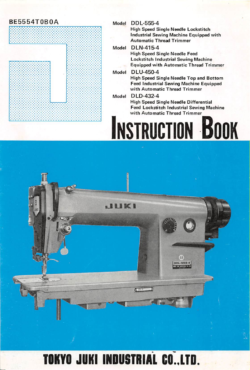
BE5554T0B0A
Model
DDL-555-4
High
Speed
industrial
Automatic
Model
DLN-415-4
High
Lockstitch
Equipped
Model
OLU-450-4
High
Feed
with
Model
DLD-432-4
High
Feed
with Automatic Thread Trimmer
Single
Sewing Machine
Thread
Speed
Single
Industrial
with
Speed
Single
Industrial
Automatic
Speed
Single
Lockstitch
Needle
Trimmer
Needle
Sewing
Automatic
Needle
Sewing
Thread
Needle
Industrial
Lockstitch
Equipped
Feed
Machine
Thread
Top
Machine
Trimmer
Differential
Sewing
Trimmer
and
Bottom
Equipped
Machine
with
Instruction
0
Book
TOKYO
JUKI
INDUSTRIAL
CO..LTD.
Page 2
This INSTRUCTION BOOK is compiled for JUKI models DDL-555-4, DLN-415-4, DLU-450-4
and
DLD-432-4
like DDL-555, DLN-4I5, DLU-450 and DLD-432. Since the basic principle of operation and
adjustment are entirely same as those of mother models, please refer to the separate INSTRUC
TION BOOK prepared for them as well.
Please do
questions
I.
SETTING
1. Installation of the machine head 1
Z
3. Installing and adjusting the pedal -
4.
5.
6.
II.
HOW
1. General instruction 6
2. Lubrication and the amount of oil 6
3.
4. How to operate the pedal 6
5.
6. Automatic counter-back stitching 9
7.
8.
9.
10.
11.
12.
13. Howto selectthe
14.
15.
16. The
17.
18.
19.
20. Howto installand
III.
HOWTOADJUST
1.
2.
IV.
HOWTOUSE
1.
2.
3.
V.
AUTOMATIC
1.
2.
VI.
SPECIAL'SWITCH
DIAGRAM
VII.
VIII. DIMENSIONAL DIAGRAMOF THE TABLE (TOP SURFACE) 24
which are equipped with the automatic thread trimmers to their mother models
not
hesitate to
or details.
UPTHE
Motor
pulley
Installing
Connecting
Confirming
TO OPERATETHE
Checking
Adjusting
Passing
the
Adjusting
Adjusting
Adjusting
Sharpening
Importantnotes '3
Adjusting
Adjusting
floating
Changing
Adjusting
Adjusting
Adjusting
Adjusting
Forming
Adjusting
Adjusting
Howtooperate
Adjusting
SHOWING
contact
with our agent in your area or our main business for further
CONTENTS
MACHINE
andbelt 1
the
synchronizer
thecords ^
the
operating
the
pedal
the pedal
needle
the thread
the
lengthofthread
the
needle
thecounter
the
timing
the
position
range
the
moving
the
bobbin
the
slide
THE
the
positionofthe
the
positionofthe
AND
ADJUST
the
switch-back
the
position
the
reverse
PRESSER
voltage
MACHINE
action
pressure
thread 10
andstroke 8
tension
stop
remaining
position
after
onthe
thread
needle
trimming
after
thread
trimming
knife
presser
foot, throat plate,
of the
thread
of the
of the
second
knife 17
thread
shaft
remove
WIPER
timming
moving
thread
presser
the knife
knife
tension
installing
sewing
hookandfeeddog 14
cam
di.sc
base 19
wiper
wiper
THE
magnet
SWITCH-BACK
BUTTON
stitches
ofthe
switch-back
stitch
FOOTLIFTER,
length
lever
AK-2
AK-2
the
presser
foot
TO HOLDTHE NEEDLE ATTHI-TOP
stroke
METHODOFASSEMBLING
POSITION
TABLE 23
....
I
3
5
6
6
•0
II
12
'3
14
15
17
18
19
20
20
20
21
21
21
21
22
22
22
22
Page 3
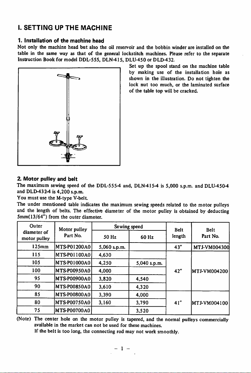
I.
SETTING
1.
Installationofthe
Not
only
table in the same way as
Instruction
Z
Motor
The maximum sewingspeed of the
and DLD-432-4 is
the
machine
Book
pulley
UP
for
and
4,200
THE
MACHINE
machine
head
but
also
that
model
of the general lockstitch machines. Please refer to the separate
DDL-555, DLN-415,
belt
s.p.m.
head
the
DDL-555-4
oil reservoir
DLU-450
Set up
by
shown in the illustration. Do
lock
of
and,
and
the
or DLD-432.
the
making
nut
too
the table
DLN-415-4
bobbin
winder
spool
standonthe
useofthe
much,orthe
top
will be cracked.
installation
is 5,000 s.p.m. and
are
installedonthe
machine
not
tighten the
laminated
DLU-450-4
table
hole
surface
You must use the M-type V-belt
The under mentioned table indicates the maximum sewingspeeds related to the motor pulleys
and the length of belts. The effective diameter of the motor
5mm(13/64")
Outer
diameter
motor
pulley
125mm
115
105
100
95
90
85
80
75
from
of
MTS-P01200A0
MTS-POllOOAO
MTS-POIOOOAO
MTS-P00950AO
MTS-P00900A0
MTS-P00850A0
MTS-P00800A0
MTS-P00750AO
MTS-P00700A0
the
Motor
Part
outer
pulley
No.
diameter.
50
5,060
4,630
4,250
4,000
3,820
3,610
3,390
3,160
Sewing speed
Hz
s.p.m.
5,040
4,540
4,320
4,000
3,790
3,520
pulley
is obtained by deducting
Belt
60
Hz
length
43"
Belt
Part
No.
MTJ-VM004300
s.p.m.
42"
MTJ-VM004200
41"
MTJ-VM004100
(Note) The center hole on the motor pulley is tapered, and the normal pulleys commercially
availableinthe
market
can
notbeused
for
these
machines.
If the belt is too long,the connecting rod may not work smoothly.
as
- 1 -
Page 4
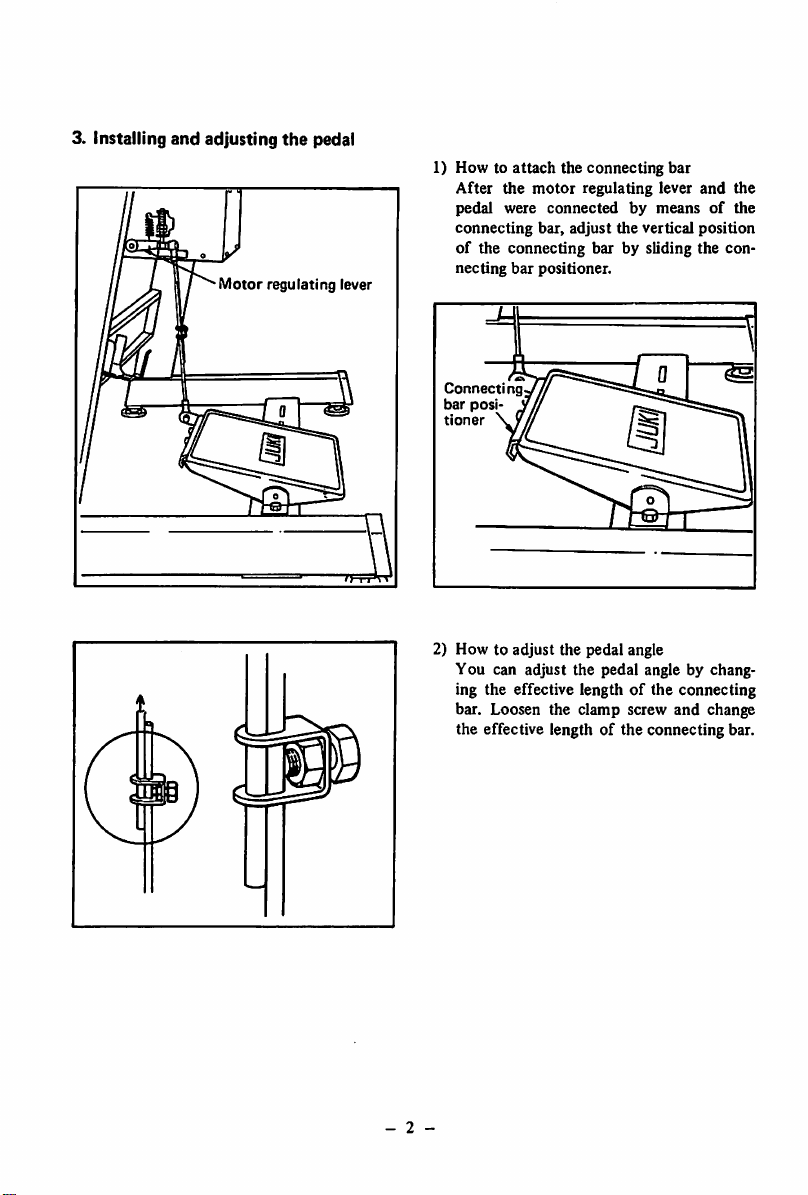
3. Installing and adjusting
Motor
the
pedal
regulating
lever
1)
Howtoattach
After
pedal were
connecting
of the connecting bar by sliding the con
necting bar positioner.
Connecting
bar
posj
tloner
2) How to adjust the pedal angle
You can adjust the pedal angle by chang
ing the effective length of the connecting
bar. Loosen the clamp screw and change
the effective length of the connecting bar.
the
connecting
the
motor
regulating lever
connectedbymeansofthe
bar, adjust
the
vertical position
bar
and
the
ft
- 2 -
Page 5
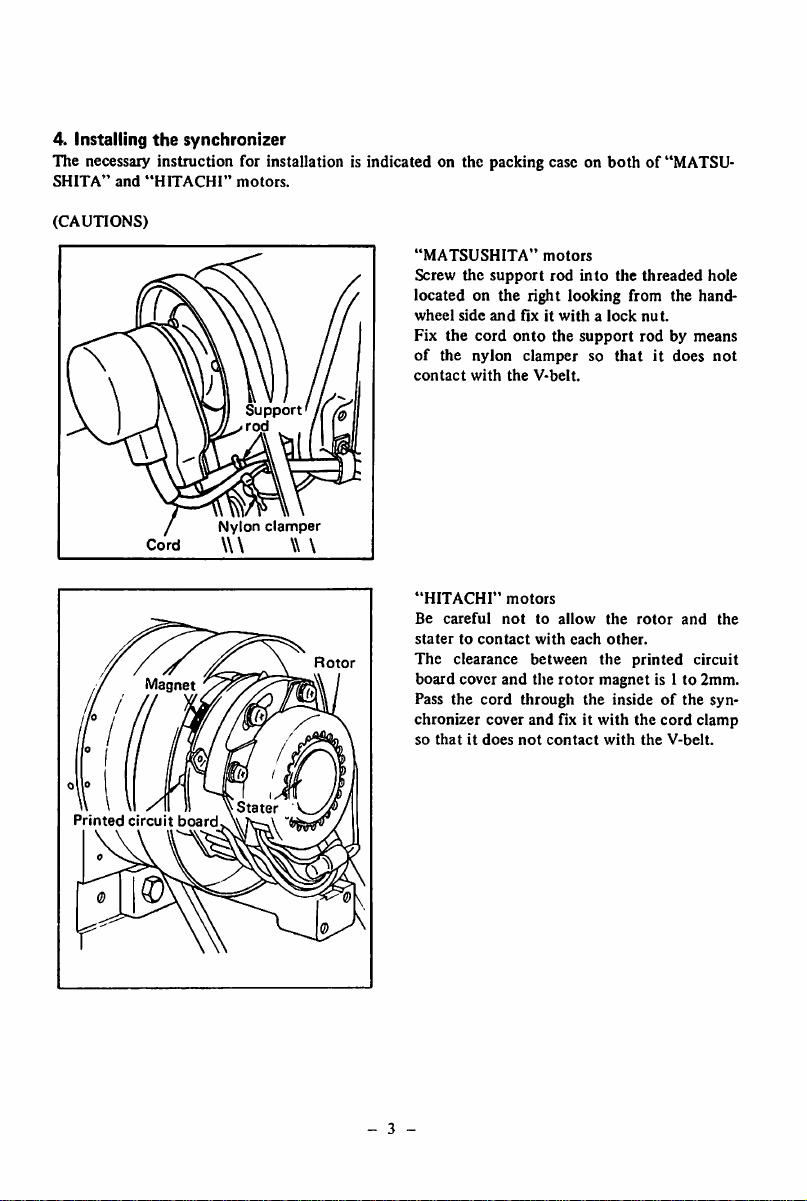
4. Installing
the
synchronizer
The necessary instruction for installation is indicated on the packing case on
SHITA"
(CAUTIONS)
and
"HITACHI"
Cord
motors.
Nylon
\\\
Support
rod
clamper
\\ \
"MATSUSHITA"
Screw
the
support
locatedonthe
wheel
side
Fix
the
of
the nylon clamper so
contact
right looking from the hand-
and
fixitwithalock
cord
onto
with
the
V-belt.
motors
rod
the
into
support
both
of "MATSU
the
threaded
nut.
rodbymeans
that
it does
hole
not
Printed
Magnet
circuit
board
Stater
Rotor
- 3 -
"HITACHI"
Be
careful
statertocontact
The
clearance
board
cover
Pass
the
cord
chronizer
so
cover
thatitdoes
motors
nottoallow
with
each
between
and
the
rotor
through
and
fix it
not
contact
the
rotor
other.
the
printed
magnet
the
insideofthe syn
with
the
with
the
and
the
circuit
is I to 2mm.
cord
clamp
V-belt.
Page 6
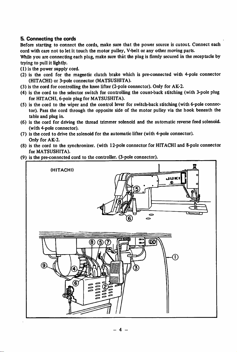
5y
Connecting
Before starting to connect the cords, make sure that the power source is
cord
with care
the
cords
nottoletittouch
the
motor
pulley, V-belt or any
other
cutout
moving parts.
Connect each
Whileyou are connectingeach plug, make sure that the plug is firmly secured in the receptacle by
trying to pull it lightly.
(1)isthe
power
supply
cord.
(2) is the cord for the magnetic clutch brake which is pre-connected with 4-pole connector
(HITACHI) or 3-pole connector (MATSUSHITA).
(3) is the cord for controlling the knee lifter (2-pole connector). Only for AK-2.
(4) is the cord to the selector switch for controlling the count-back stitching (with 3-pole plug
for HITACHI, 6-pole plug for MATSUSHITA).
(5) is the cord to the wiper and the control lever for switch-back stitching (with 6-pole connec
tor). Pass the cord through the opposite side of the motor pulley via the hook beneath the
table
and
plug
in.
(6) is the cord for driving the thread trimmer solenoid and the automatic reversefeed solenoid,
(with
4-pole
connector).
(7) is
the
cordtodrive the solenoid for
Only
for
AK-2.
(8) is the cord to the synchronizer, (with 12-pole connector
for
MATSUSHITA).
(9) is the pre-connected cord to the controller. (3-pole connector).
HITACHI
the
automatic
lifter (with 4-pole connector).
for
HITACHI and 8-pole connector
UUKI
- 4 -
Page 7
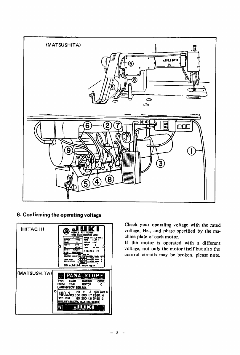
(MATSUSHITA)
6. Confirming the operating voltage
(HITACHI)
.
aJUBCI
' KEfOlC
wttt
rnw
I^OSITIOKCA
iKDWiei
itni
wto«
•«
UM-«
Check your operating voltage with the rated
voltage, Hz., and phase specified by the ma
chine
If the
voltage,
control
plateofeach
motor
not
circuits may be
motor.
is operated with a different
only
the
motor
itself
but
broken,
also
please note.
the
(MATSUSHITA)
PANA
enam
Eucrmc
SER.Na
200
60
200l£3450
iwwsTim
STOPE,
rating
type
FORM TSAI ROTOR
LAMP6V20W
400w2poUSO
V7I-I0M
masusHnA
1.7
288^
caiin
CONT.
C
cooeO
H
G
- 5
Page 8
II. HOW
1.
General
After
hand,
watching
from the open side of the handwheel.
If you fail to judge it, you can repeat to
found.
o Clean up the installed machine.
o
Before
DDL-555,
oDonot
oDonot
machine
after the first 1 month has passed,
o Keep awayfrom the needledropping placewhen you switch the machine on.
o Do not fail to switch off the machine before you tilt the machine head backwards for lubrica
tionor
will
motor
o Whenyou move the machine to other places, to not hold it with the cover located on the rear
of
o
Even
ed on or the thread is trimmed, the needle would not come down or the thread trimmer would
not
forwards (toe-down).
2.
Lubrication
Beforestarting to operate the
JUKI
TION
3. Checking
o Firstly, check your machine without passingthe threads.
o
Switch
Even
by switching on the machine,
o When you switch on the machine, do not put your hand under the needle.
4. Howtooperate
As
the
(1) Placeyour feet gently on the pedal at the stop position.
(The needle is held at the lowest position).
(2) Tread on the pedal lightly forwards (toe-down), and the machine starts to rotate at a low
speed.
(3)
Treadonthe
gradually
the switch for the counter-back stitching is turned on, the machine will attain it's maximum
sewing
the
TO
OPERATE
instruction
the
machine
switchonthe
the
has
been
machineontril
rotationofthe
startingtooperate
DLN-415,
drive
replace
at a
DLU-450orDLD-432.
the
machine
the
motor
higher
speed
clearingorremoving
be stopped immediately by
assembly.)
the
handwheel.
if you tread on the pedalbackwards (heel-down) immediatelyafter the machineisswitch
work.
Such thread
and
amountofoil
industrial
BOOK.
the
following
pedal
on the
needle
speed
lubricating
the
pedal action
machine,
staying
the
illustration
pedal
and
attain
only after the
fully.
further
the
set
handwheel.
the
before
pulley
depending
the
trimming
machine,
oil.
Refer
and the
at a
lower
pedal
shows,
maximum
THE
MACHINE
up,
bring
down
and
check
The
machine,
theoil
V-belt.
means
needle
forwards
count-back
read
reservoirisfilled
withalarger
on the
(If
of the built-in safety
motion is
fillthe oil
to the
will
position
the pedalof this
(toe-down),
speed
the
needlebyrotating
that
the
motor
handwheel
switch
on and off the
through
the
one
within
necessityofsewing
you
mistakenly
performed
corresponding
beheldat it's
willbebrought
whenithas
stitch has
only after the pedalhasbeentrod once
reservoir
model
and
been
the
handwheel
rotatesinthe
must
rotate
machine
separate
with
the
lubricating
first1month.
works
tread
onthe
device
up to the "HIGH" marked
paragraph
highest
position
upand
isoperatedin4
the
machine
been
trod
formed,
correct
counterclockwise
until the direction is
INSTRUCTION
oil.
You
and
operator's
pedal,
separate
without
at the
stages.
will
fully.
though
the
increase
in the caseof "HITACHI"
in the
held
down
even
with
direction
watching
BOOK
may
operate
motor
level
INSTRUC
fail.
highest
it's
However,
you tread on
your
the
ability
pulley
with
position
speed
when
by
of
- 6
Page 9
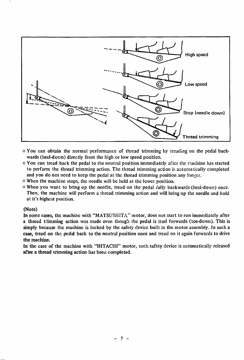
High
Low
speed
speed
©
Stop
Thread
(needle
trimming
down)
o You can obtain the normal performance of thread trimming by treading on the pedal back
wards (heel-down) directly from the high or low speed position,
o You can
tread
back
the pedaltothe
neutral
position
immediately
after
the
nachine
has
started
to perform the thread trimming action. The thread trimming action is automatically completed
not
and you do
need to keep the pedal at the thread trimming position any longer,
o When the machine stops, the needle will be held at the lower position.
o When you
want
to bring up the needle, tread on the pedal fully backwards (heel-down) once.
Then, the machine will perform a thread trimming action and will bring up the needle and hold
at
it's
highest position.
(Note)
In
some
cases,
the
machine
with
"MATSUSHITA"
motor,
does
not
starttorun
immediately
after
a thread trimming action was made even though the pedal is trod forwards (toe-down). This is
simply because
tread
case,
the
machine.
In tlie
caseofthe
the
machine is
on the pedal
machine
locked
backtothe
with
"HITACHI"
by the
neutral
safety
position
motor,
device
built
in tlic
motor
assembly. In such a
once
and tread on it again forwards to drive
such
safety
device is
automatically
released
after a thread trimming action has been completed.
- 7
Page 10

5. Adjusting the pedal pressure and stroke
(MATSUSHITA)
Pedal
pressure
spring
1) Adjustment of the forward pressure
Adjust the forward pressure by changing
the position of the spring.
"HITACHI"
motor:
The pressure is reduced by moving the
spring to the left and is increased to the
right.
"MATSUSHITA"
motor:
The pressure is reduced by moving the
.spring
to the right and is increased to the
left.
Adjustment
Adjustment
nutofthe
backward
pressure
spring.
(MATSUSHITA)
grooves
(HITACHI)
Connecting
-—(upper)
(HITACHI)
I
rod
2) Adjustment of the backward pre.ssure
"HITACHI"
motor:
The backward pressure can be adjusted by
means of the adjustment nut of the back
ward pressure spring. The pressure is in
creased by tightening the
reduced by loosening.
.spring
3) Adjustment of the pedal stroke
The pedal stroke can be adjusted by
changing the connectionofthe upper
connecting rod with the motor regulating
lever.
"HITACHI"
The
rod
with
increased by the right
"MATSUSHITA"
The
motor:
.stroke is reduced by
the
left
hand
sideofthe
hand
motor:
stroke
is reduced by
connecting
lever
side.
connecting
rod with the riglit hand side of the lever
and is increased by the
left
hand
side.
and
the
and
the
- 8
Page 11

6. Automatic count-back stitching
You
can
form
the
without
operationofthe feed
BACK
START
ENDdTO)
•JUKI
count-back
Count-back
at
'
Count-back
at
TAC
SW.
(»i^)
stitches
control
the
the
stitch
start.
stitch
end.
TTsr
Selector
formingacount-
back
startofa
Selector
formingacount-
back
endofa
switch
stitchatthe
seam
switch
stitchatthe
seam
J
at thestart
and/or
theend of a
leverorswitch-back lever.
1) You can preset the machine to form the
count-back
endofthe
selector
2)Ifthe
enough for your sewing purpose, turn
the
selector
sary lengthofreverse
making usofthe reverse feed
or
the
switch-back
3)
When
turned
automatically
ately by treading on the pedal backwards
before or after forming the count-back
stitchatthe
for
iine.
for
line.
though you tread on the pedal for thread
trimming while the count-back stitch is
being formed, the thread trimming action
will
not
tionofthe
4)
When
the
turned on, the thread trimming action will
be
performed
has
been
If you tread on the pedal for thread trim
ming while the machine is forming a
count-back
line,
the
after completing the said count-back stitch.
seam
line
automatically
stitchesatthe
seam line by
switches.
numberofcount-back
switch
and
stitches
start
meansofthe
stitchisnot
produce
manually by
and/or
the
control
lever.
the
selector
on,
you
can
trim
startofa
switch
off
let
the
for
the
thread
seam
"Start"
machine
immedi
line.
be performed prior to the forma
said
count-back
selector
after
formedatthe
stitchatthe
machine
will
switch
the
endofa
trim
stitch.
for
"End"
count-back
seam
endofa
off
the
thread
the
off
neces
lever
is
to
Even
is
stitch
line.
seam
- 9 -
Page 12

7. Passing
(D
the
needle thread
(D
©
(4)
oIfthe
machine
stops
ing the needle at a lower
position, tread on the pedal
backwards
an idle
before passing
thread.
thread
Then,
for
performing
the
the
trimming
will go up and stay at
highest position,
o
Pass
the
needle
thread
the order fromCDto © as
showninthe
illustration.
leav
needle
needle
the
in
©
8. Adjusting
Tension
decreased
the
thread tension
Tension
increased
(The
length
remaining on
adjustable with the disc.)
Tension
\
increased
Thread
disc
Tension
decreased
(The
is
adjusted
this
Thread
disc
No.2.
thread
disc.)
No.1
of a
the
tension
tension
thread
needle is
tension
with
©
Refertothe
ately prepared for the model DDL-555,
415, DLU-450 or DLD-432 for the method of
thread tension adjustment excepting the fol
lowing points;
1) Adjustment of the thread tension spring.
If the thread tension spring of
chine
or synthetic fiber thread like
Nylon thread has an excessive tension or
stroke, it may produce some skipped
stitchedatthe
cordingly the thread may not be trimmed
off
INSTRUCTION
whichisthreaded
endofa
normally.
withathin
seam
BOOK
Tetoron
line
your
separ
DLN-
cotton
and
ma
or
ac
-
10
-
Page 13

2)
Adjustment
of the thread tension disc
No.l
o o The length of a thread remainingon the needle is shortened by increasingthe tension of the
disc No.1 and is lengthened by decreasing the said tension,
o
Wlien
you use a thin thread (like a synthetic thread), reduce the tension properly. On the
other
hand,
when
you
use a
thick
thread, increase the tension.
3)
Adjustmentofthe
o The methodof adjustmentis
o If you reduce the
thread
tension
tension
disc
No.2
same
as that of
normal
too much,it maycausea thread
lockstitch
breakage
sewing
at the start of
machines,
sewing.
9. Adjusting the length of thread remaining on the needleafter trimming
o The length of the thread remaining on the needle after the thread trimmer has worked is
closely related with the
from
judge it
a floated needle thread or
o You can adjust the length of remainingthread by means of the thread tension disc No.1.
o It is
possibletochange
threads,if
necessary.
correct
formation of stitchesatthe
bobbin
threadatthe
the
timing
of the thread
Please
consult it with our agentor our main businessoffice.
trimming
startofa seam line.
start
between
You
of a seam line,
the cotton andsynthetic
can
-
11
-
Page 14

10. Adjusting
the
needle
stop
position
after
thread
trimming
You can adjust the position at which the needle stops after a thread trimming has been com
pleted.
The standard needle stop position is shown by the coincidence of the white
hand
wheel with the red
installation angle of the sensing element of the synchroniser
Instruction Book prepared for the
dod
on the machine arm. This adjustment can be made by changing
component
motor
assembly for the detailsofadjustment.
dot
marked on the
Refer to the separate
the
White
Red
dot \ j .
dot
Printed
board
circuit
cover
Rotor
Magnetic
n
flange
"HITACHI**
Remove
component
of
the
justable range of the oval holes on
the
and
printed
motor:
cover
adjust
circuit
from
the
the
installation angle
board
synchronizer
within
the
the
rotor
flange.
"MATSUSHITA**
Remove
the
cover
motor:
from
the
synchronizer
adjust the installation angleofthe magnetic
plate.
ad
and
-
12
-
Page 15

11.
Sharpening
Horn
Sharpen
Needle
this
this
Blade
Moving
center
corner
face
tip
knife
the
counter
a
Counter
knife
knife
o As
soonasyou
trimmer
counter
has
knife
o Put the resharpened
noticed
become
immediately,
dull, resharpen
counter
that
knife
the
thread
back
it's correct position shown by the following
illustration.
oIfyou
move the installing positionofthe
counter
position,
the
needle
and
vice
knife to
the
versa.
the
length of
after
right
thread
trimming
Bottom
the
throat
from
face
the
standard
remaining on
becomes
of
plate
the
to
longer
*Do
not
re-sharpen the moving knife.
12.
Important
o Allow the
Shorter
The
remaining
of
the
thread
notes
thread
spool to supply thread to the machine freely.
length
becomes;
Longer
Stepped
of
Counter
the
bed
knife
part
(If not, the length of the remaining thread on the needle after thread trimming may be too
shorttostayonthe
needle.)
o If skipped stitches are produced, the thread trimmer may trim only the bobbin thread.
In such a case, adjust
skipping
stitches.
the
timingofthe needle and the
-
13
shuttle
race in
order
to remove such
Page 16

13. How to select the presser foot,
1)
Presser
foot
(
n
nz
2) Throat plate
Na
throat
plate, sewing hook and feed dog
1) Ptesser foot: Select small a and b parts.
2)
Throat
plate: Select small needle eye and
A
part.
3) Needle: Finer needle for less thread slip
page.
4) Sewing hook: Automatic lubricating
with
a groove.
5)
Feed
dog: If a feed dog which is
ly used is adopted, there is no problem,
but
if an extremely thick feed dog is used,
the backside of the dog teeth might be
.scratched when the moving knife moves
fully.
hook
common
14. Adjusting
the
timing of
DLD-432-4
the
thread
trimming cam
1) How to Judge the correct timing of the
trimming cam
In
order
to change
the
lengthofthe
remainingatthe needle eye after trimming,
adjust the timingofthe thread trimming
cam.
This
can be
done
the
arm
with
hand
wheel, according to the
thread
used-cotton
Tilt
the
machine,
your
hand
before
until
the
Just
the
turn
the
upper
easily by
indicated
or
the
thread
dead
sewing hook presser (D is pushed deeply
to right,
grooveofthe
there.Inthat
wheel
conventional
come
any
matched
arm ®
wheel (f) are matched together as shown
in the fig., it becomes a
timing.
the
cam
roller
cam
and
condition,
in
the
reverse
way,
to a
point
more. At this
so
that
and
the indicated lineofthe
direction
and
the
where it will
point
the
indicated
But if the indicating line 0 is
matched with the indicating line®,it
becomes a timing for
synthetic
matching
line
on
kind
synthetic
hand
thread.
wheel
take-up
point
andifthe
will
enter
the
will be
interlocked
rotate
the
than
hand
wheel
not
if cam timing is
lineofthe
cotton
thread.
thread
the
of
with
comes
cam
hand
the
will
rotate
hand
thread
-
14
-
Page 17

Thread
trimnning
cam
Cam
roller
Cam
roller
shaft
arm
set
screw
2)
Howtomatch
Rotational
Rotate
this
with
the timingofthe
First, loosen the 2 set screws
match
the indicating lineofthe
cam
direction
hand
direction
Set
in
thread
of
the
Thrust
collar
screw
trimming
arm
trimming
cam
caminorder
with
the indicating lineofthe
Green (6)
from
set screw
hand
No.l
wheel.
and
(For
thread, match red color ® with the red color (5) and for synthetic thread, red color ® with
the green color
®).
Then, by pushing the sewing hook presser @ to right, interlock the cam and the cam roller,
and
the normal
cam does
and
15.
Adjusting
without
finally
•2.5mm'
rotating
hook
not
tighten
the
the
hook
shaft rotational direction with
rotate
any more, push the cam against the
the
cam
set screws in
positionofthe
Needle
Moving
shaft,
moving
knife
rotate
the
orderofNo.2
knife
the cam
your
1) The
when it has
is, as
moving
(1/6-^3/32")
When
position, it
bobbin
while if
the
Therefore,
the
only
toward
the
reverse
direction
finger tips. At the position where the
thread
trimming cam
and
No. I.
correct
positionofthe
movedtoits
shown
in fig., when
knife
has
from
the
retreated
cannot
threadatthe
it's
too
moving knife
it is
retreatedto2~2.5mm
the
centerofthe
range is less
scoopupthe
much,
might
very
importanttomatch
thrust
moving knife
maximum
the
trimming
the
feed
hit
each
tipofthe
positionofthe moving knife correctly.
No.2,
cotton
needle.
than
needle
instant,
dog
other.
and
than
collar
range
this
or
and
-
15
Page 18

2) How to
match
knife.
Thisisadjusted
the positionofthe moving
by changing tlie right or
left position of the movingknife shaft ®
when the machine stops. By this adjust
ment, the interlocking
of
cam roller also changes, so match the
positionofthe
ward
the
shaft
thread
direction,
trimming
also.
a. First, loosen the magnet set screw (2)
and pull out the magnet link pin (3).
b.
Move
the magnet link ® downwards
and adjust the screwed-in amount of
the knife moving
CD.
If this nut is screwed in deep, the
shaft
retreating range of the knife becomes
greater
andifit's
loosened,
gets less.
c.
Loosen
both
set screwsoftrimming
cam ® and the thrust collar
d. Match the indicating lineofthe
wheel with the indicating lineofthe
arm.
(In case of
cotton
thread,
with ® of the front
synthetic thread, match @ with
e.
Rotate
the set screw
No.2®
point)ofthe trimming cam so
comestofront
and
whenitcomes
front, push the sewing
right.
f. Move the cam to right and left and
interlock
g. With this
cam
direction
anymore.
h.
Temporarily
®
i. Tighten the lock
the
condition,asyou
to right,
until
of
the cam.
cam
and
the
moveittoward
the
cam
tighten the set screw No.2
nut
®.
j. At this point, verify the following:
(T)
Is the indicating line of the pulley
matched?
@ Is the roller inserted smoothly into
the cam groove?
® Is the retreated range of the moving
knife
k.
Tighten
securely.
16
-
2~2.5mm?
the
two
set
screwsofthe
the cam and the
cam
adjusting
the
nut
range
hand
match
fig.
and for
®).
(indicated
that
hook
prcsser to
cam
roller.
pull
the
the
arrow
cannot
rotate
cam
to
®
it
to
Page 19

1.
Push the thrust collar against the cam and tighten the two set screws,
m. Attach the magnet link pin in its original position.
The
simple
methodtojudgethe correctpositionof the
moving
knife
would
be to
verify
if the
step part of the bed and the forked base of the knife are parallel to each other. If they are
parallel,
the
positioniscorrect
(Note) 1) No matter how slight the right or left position adjustment may be, it has a big
bearingon the retreating rangeof the movingknife.
2) Verifyif the movingknife disposesthe thread properly as shown in
fig.
16. The floating range of the second thread tension disc
1) How to verify the floating range
At
the
position
come
just
lower
the
thread
presser is
verify
that
thread
tension
2) Adjusting the floating range of the second
thread
tension
(T)
To increase the floating range, loosen
nut
(B)
(DTo decrease the floating range, loosen
nut © and tighten nut
17. Changing
the
@ (D ©
moving
knife
After the adjustment is completed, tighten
both
® and © nuts.
To change the moving knife, do as follows:
1) Loosen the knife forked base pin set screw
(Fig.C®)and pull out the knife forked
base
pin
(Fig.C
2) Remove the moving knife hinge screw
(Fig.A
®),
(Fig.A
d))
to the position shown in Fig.B (I) and
remove the pin of the moving knife from
the
knife
forked
3) Move the knife forked base to the position
shown in Fig.B© and remove the knife
Fig. A
hingedscrew(Fig.B(D ). For this purpose,
u.se
the
box.
special
For installing back, reverse the above procedure. After the knife hinged screw is tightened, move
the moving knife with your hand and see if it moves smoothly without any rattling. Match the
knife forked base to the position shown in
Fig.B
(D and firmly insert the knife forked basepin
into the forked base. (If the knife moving shaft is moved to right or left, the pin willgo in deep
into the base). When the shaft is moved to right, be sure to see that the knife moves to right, also.
where
the
take-up has
before
the
upper
dead
presser
foot
and
when
the
pushed
hard
the
floating rangeofthe second
discis0.5~lmm.
disc.
to right,
and tighten nut (§).
(g).
d)).
move the knife forked base
and the
moving
knife
(Fig.ACD)
ba.se.
spanner
in the acces.sories
point,
hook
-
17
Page 20

Knife
Moving
forked
base
knife
Knife
forked
base
Knife h!nged_
screw
/
Moving
knife-
Knife
Moving
forked
base
knife
Fig. BCD
18. Adjusting
the
If the bobbin thread
bobbin
presser
thread
(Fig.C
Fig. B(D
Fig. B(D
presser
(D ) is penetrating too deep toward the bobbin caseat the
trimming time, the bobbin will not rotate and the bobbin thread will be trimmed too short,
causing thread slippage at the start of sewing.
On
the
the
contrary,
bobbin
thread
if it is not
presser
inserted
at the
deep
trimming
enough,
time,
the
needle
shortening
thread
the
thread
will
slip
remaining
out
from
amount
thetipof
at the
tip of the needleeye after the trimmingand invitesthreadslippingout.
1) The correct position of the bobbin thread presser
When
the thread trimming lever is pressed hard against the stopper side, the bobbin thread
should
be pulledout
the bobbin thread
shown in Fig,D.
2) How to adjust the bobbin tliread presser
Loosen
the
.screws
easily.
At this
pre.sser
position,
and the upper carved part of the bobbin should be 1.5~2mm as
(Fig.C
® ), and
adjustbymoving
the
clearance
the
between
bobbin
the tip
thread
(Bobbin
presser
presser)
inand out or
up ond down. At this instant, adjust the fore and aft position of the bobbin thread presserand
adjusttheposition of the thread
After
adjusting,
tighten
the set
shaft is not contacting the bottom of the cam
trimming
screw
stopperarmas shownin the
of the stopper. Besure to
groove
figure.
verify
that the tipof the
roller
when the stopper isdeeplyinserted. If
it's contacting, refer to the chapteron"Adjustingthe slideshaft" and re-adjust the positionof
the
slide
shaft
collar.
1.5
~2mm
T
Ea
of
-18-
OLO-432-4
Page 21

19.
Adjusting
20.
Howtoinstall
the
slide
and
shaft
remove
20mm
13.5mm
the
Q>.
knife
The
moving
range
of the slide shaft (D is
5.4mm{7/32"). This is adjusted by moving the
slide collar (D toward the shaft direction. Alsp,
the position of the cam roller shaft arm (D
should be
* The adjusting procedure is as follows;
® Determine the position of the thread trim
13.5mm(33/64")
ming arm
positionofthe
stopper
hook
as shown in fig.
depending
thread
presser.
(D Adjust the position of the slide collar so
that
the moving range of the slide shaft
comes to
5.5mm(7/32").
(D Adjust the position of the thread trimmer
magnet
(DC
When
the
the
position
solenoid).
thread
trimming arm has moved to
where it is
almost
touching
stopper, adjust the position of the thread
trimming magnet so
is
attached
plunger
hits
the
to the
rubber
that
the snap ring which
thread
trimming
ring
and
stops
when the magnet is pulling, there should be
no
rubber
installing
clearance
base
ring.
between
the
two
To remove the knife installing base 0 do as
followsinorder:
1)
Take
out
the
sewing
hook.
2) Loosen
out
3) After removing the
link hinged screw
the
the
knife
knife
forked
forked
base (5) and. pull
base pin (§).
hook
(0,
and if the hook
thread presser
presser hinged screw 4 knife installing base
set screw (2) is pulled
out,
installing base will come off. To install
back,
reverse
this
order.
upon
the
the
magnet
and
also
endsofthe
the
knife
-19-
Page 22

Hi.
HOW
TO
ADJUST
1.
Adjusting
You
must
adjust
the
the
in the following way;
THE
positionofthe
positionofthe
WIPER
wiper
wiper according to
the
thicknessofthe
Rotate
1)
the handwheel manually in the
normal direction so
on
the
handwheel
dot(Don
the
that
coincides
frame.
materialtobe sewn
the white
with
dot
the
red
(D
2) Insert the wiper ® into the wiper driving
shaft (D so
tween
becomes
clearance
that
the
wiper edge and
2mm
and
between
the
vertical clearance be
the
the
needle
needle
parallel
also
the
center
point
and
the straight inside faceofthe wiper be
comes 1mm. Fix the wiper at such a
position by tightening the lock
nut
(3).
2.
Adjust
Wiper
the
positionofthe
switch^
2mm
M
wiper
magnet
Pull the plunger fully
into
the
coil, loosen
screw ® which is clamping the wiper magnet
and adjust the positionofthe wiper magnet
so
that
the wiper tip is positioned with a clear-
ranceof2mm
the
needle.
After a
the wiper magnet at
ing
the
When you do
wiper switch.
-
20
-
from
the
center
correct
position has been obtained, fix
that
screw.
not
position by tighten
use the wiper,
line
of
turn
off
the
the
Page 23

IV.
1.
Forming
HOW
TO
USE
the
switch-back
ANDADJUST THE
stitches
Switch-back
button
SWITCH-BACK
1) Push the switch-back button, and the ma
chine will perform a reverse feed to form
the
switch
back
BUTTON
stitches.
2)Aslong as the button is kept pressed, the
machine will perform
the
reverse feed.
3)Assoon as the button is released, the
4)
machine
When
reverse
will reversed to the
normal
feed.
you sew the half stitches, use the
feed
control
lever.
Z Adjusting
I
3. Adjusting
the
the
reverse
position of
stitch
the
switch-back lever
length
You
may
change
the
positionofthe
switch
back button to a suitable height for your
operation. Loosen the screw (D, move the
switch lever up and down and obtain a suit
able height. Tighten the
adjustment.
An excessive length of reversestitch is usually
formed
by the operator until he gets
operate
this
new
In such a case, it
en the seam line with the reverse feed by
decreasing the stitch length of reverse feed in
comparison with the stitch length with the
normal feed, if it is permissible. To lessen the
length of the reverse stitch, loosen the screw
(D
and
push
push it
down
lengthsofthe
identical.
device.
would
up the
to the
normal
screw
firmly after
be advisabletoshort
stopper
bottom
and
plate
end. the stitch
reverse
used
(2).Ifyou
feeds
are
to
-
21
-
Page 24

V.
AUTOMATIC
PRESSER
FOOT
LIFTER,
AK-2
(Optionalattachment)
The automatic
presser
been made. A special
1.
Howtooperate
presser
foot lifter
foot and holdingit at the
motor
is used for this lifter AK-2.
AK-2
AK-2
is an optional attachment
heigliest
position for 10 to 15secondsafter thread
which
is capable oflifting the
trimming
If you want to raise the presser foot during a
sewing work, press the
knee
switch.
Such raised presser foot will be comming
down
immediately
released.
after
the knee switch is
If you want to bring down the presser foot
which
has
been
Knee
2.
Adjusting
switch
the
Coupler
presser
lifter
stroke
the
and release
the
lock
knee
rai.sed as
the
matic run, tread on the pedal forwards (toe-
down)orpush
1. Loosen
2. Lower the presser
by loosening
3.
Push
the
resultofan
the
nutofthe
foot
stopper
lock
nut.
switchtodrive
knee
switch.
coupler.
the
(A) fully
4. You can adjust the stroke of the presser
foot by rotating the plunger on the far
Presser lifter
Tighten the lock
Loosen the
lock
Presser
nuts
nutofthe
stopper
Presser
stopper
V.
lifter
of the
lifter
(A)
lever
stopper
stopper
(B)
(A) and the
(B), push the presser
sideofthe
by a
a
counterclockwise
(The
presser
5. Raise
voir by activating the solenoid.
6. Raise the
ther
switch.
coupler
solenoid;
clockwise
maximum
footisabout
stopper
(A)
stopper
half
turn
respectively.
lifter
lever
the
strokeisincreased
turn
andisdecreased
turn.
stroke
performedbythe
8mm(5/16")).
untilithits
(A) by
after
releasing
towards
the
the
rotatingitano
the
solenoid
your hand and adjust the height of the stopper (B) so that the playing gap between the top
end/of the knee lifter rod and the knee lifter connecting rod located on the machine head
become about
lmm(3/64").
After obtaining a proper position, retighten each lock nut.
has
auto
solenoid.
by
oil reser
knee
with
VI.
SPECIAL
(Optional
SWITCH
TO
attachment)
HOLD
THE
NEEDLE
AT
THE
TOP
POSITION
We are also ready to supply you with a special switch to hold the needle at the top position when
the machine is stopped during a sewing work with the pedal at the neutral position. This switch
is operated with
business
office.
your
knee.
For
further details, please
—22—
contact
our
agent in
your
area or our main
Page 25

Diagram
JZ-D31
Showing
MethodofAssembling
Table
88101-552-000
SM-9082023-SE
WP-0871602-SE
WS-0861410-KR
S0-1204215-SE
WP-1252210-SC
WS-1253010-KN
80207-012-000x2
88209-125-000
x4
x4
x4
x4
x4
x4
B8216-012-0A0
x2
B82O4-552-A00
SK-l2IIOOO-SCx6
88204-552-800
88203-552-000
D7114-555-BA8
88126-552-OAE
SM-9082023-SE
WP-0871602-SE
WS-0861410-KR
MM-6080721-SE
88102-552-000
88104-552-000
08212-125-000x2
88213-125-AAOX2
08201-555-COO
x2
SK-3514000-S0X4
88105-552-000
D8112-555-80E
SM-9061203-SE
WP-0671016-SE
WS-0621210-KRX3
88111
552-000
x3
x3
88103-552-000
88112-552-000
WP-0871602-SE
WS-0861410-KR
SM-9082023-SE
88110-552-000
gg.
NM-6120003-SE
88107-552-000
08113-555-800
x2
x2
x2
x2
D8II4-555-BOE;
SM-9082023-SE
WP-0871602-SE
WS-0861410-KR
NM-6080721-SE
x2
08110-555-BOE
08115-555-800
88108-552-000
88109-552-000
—23—
Page 26

DIMENSIONAL
DRAWER
INSTALLING
POSITION
STOPPER
INSTALLING
POSITION
DIAGRAM
(525)
OF THE TABLE (TOP SURFACE)
339.7
^08.5
depih
POWER
SWITCH
POSITION \
(holM)
30
SOURCE
—100
I
holt})
INSTALLING
•BTpnTr
618
(holfrt)
Page 27

TOKYO
JUKI
TOKYO
HeadOffice & Plant: 2-1,8-chome, Kokuryo-cho, Chofu-shi,Tokyo, Japan
Business
Cable:
JUKI
Office: 23-3, Kabuki-cho 1-chome,Shtnjuku-ku, Tokyo 160. Japan
JUKI
TOKYO
INDUSTRIAL
Telex:
22967;
232-2301
CO.,
LTD.
ii?:
'
?j:inted in
Japan(T)
 Loading...