

Page 1
BE5554S0B0A
w
MODEL
High
Speed,
Industrial
Automatic
DDL-555-4
Single
Sewing
Thread
Needle.
Machine
Trimmer
Instruction
nJ
U
Kl
Lockstitch
Equipped
with
Book
TOKYO
JUKI
INDUSTRIAL
CO..LTO
Page 2
INSTRUCTION
BOOK
JUKI DDL-SSS-4 model is designed to sew white shirt, blouse and similar articles using general
shirtings
Especially,
and others are designed for high-speed operations, so
a high speed
Carefully read through this Instruction Book
conditionatall
and
many
other
the
componentsofthis
without
times.
materials.
vibrationornoise.
model
suchasthread
that
and
operate
take-up, sewing
hook,
feed mechanism
the machine is satisfactorily operated at
your
machine in the
optimum
sewing
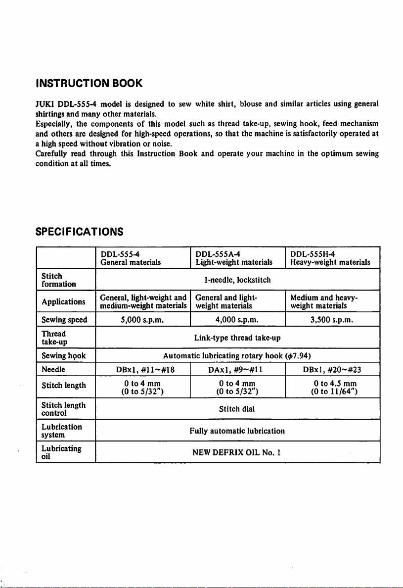
SPECIFICATIONS
Stitch
formation
Applications
Sewing
speed
Thread
take-up
Sewing
hpok
Needle
Stitch
length
Stitch
length
control
Lubrication
system
Lubricating
oil
DDL-555-4
General
materials
General, light-weight
medium-weight materials
S,000
s.p.m.
and
Automatic
DBxI,#ll~#I8
0to4
mm
(0to5/32")
DDL-555A-4
Light-weight materials
1-needle,
General
and
lockstitch
light
weight materials
4,000
s.p.m.
Link-type
thread
lubricating
rotary
DAxl,#9~#Il
0to4
mm
(0 to
5/32")
Stitch
dial
Fully
NEW
automatic
DEFRIX
lubrication
OIL
take-up
hook
No.
DDL-555H-4
Heavy-weight materials
Medium
and
heavy
weight materials
3,500
s.p.m.
(07.94)
DBxl,
#20'-#23
0to4.5
(0 to
11/64")
1
mm
Page 3
CONTENTS
I.
INSTALLATION
1. Attaching the thread
2. Installing the oil reservoir 1
3. Motor pulley and belt 2
4. Installing and adjusting the pedal 3
5. Installing the synchronizer 4
6. Connecting the cords 5
7. Confirming the operating voltage 6
8. Mounting the belt cover and bobbin winder on the table 7
stand
to the table I
I
II. HOW TO
1.
2.
3.
OPERATE
General
instruction
Lubrication
Checking
THE
MACHINE
and
amountofoil 9
the pedalaction 10
4. Howto operate the pedal 11
5. Adjusting the pedal pressureandstroke 12
6. Automatic count-back stitching 13
7.
Passing
the needlethread 14
8.
Bobbin
9.
Adjusting
thread
the threadtension 16
15
10. Attaching the needle 17
11. Presser
foot
18
12. Stitch lengthadjustment 19
Reverse
13.
HI. ADJUSTMENT 20
1.
stitchingby
Feed
mechanism 20
using
the
reverse
feedcontrol
lever
19
2. Replacingthe sewinghook 22
3. Sewinghook position related to the needle 23
4. Heightof the presserbar 24
5. Thread take-upaction 25
6. Returningpressureof the
7.
Adjusting
8.
Sharpening
IV. HOWTO ADJUST THE WIPER 28
1.
Adjusting
2.
Adjust
V. HOW TO USE AND ADJUST
1. Formingthe
the
needle
the counterknife 27
the positionof the wiper 28
the
position
switch-back
reverse
stop
of the
feedcontrol lever 25
position
after
thread
trimming
wiper
magnet
THE
SWITCH-BACK BUTTON 29
stitches 29
26
28
2. Adjustingthe position of the switch-backlever 29
3. Adjustingthe reversestitch length 30
8
8
VI.
AUTOMATIC
1. How to operate AK-2 30
PRESSER
FOOT
LIFTER
(AK-2)
2. Adjusting the presser lifter stroke 30
VII.
TROUBLES
VIII.
DIAGRAM
IX. DIMENSIONAL DIAGRAM OF THE TABLE (TOP SURFACE) 36
AND
CORRECTIVE
SHOWING
MEASURE 31
METHODOFASSEMBLING
TABLE
30
35
Page 4

I.
INSTALLATION
1.
Attaching
the
thread
standtothe
table
Assemble the thread stand and set it up on the machine table by using the installation holes in the
tableasillustrated.
Do not tighten the clamping nut too much. When power source issupplied by the overhead wires,
pass the power supply cord through the spool rest rod.
2. Installing
oi
Operator
the
Rubber
side
oil reservoir
cushion
reservoir
j-vf-r
Hinge
side
Install
the
oil
reservoirinsuchamanner
is supported by the 4 corners of an opening in
the
table.
1. Nail in the 2 felt pads of 4 mm (5/32")
thicktothe2corners
near
the
2. Nail in the 2 felt pads of 6 mm (15/64")
thick
to the remaining 2
side).
3. Place
4.
5.
- 1 -
Insert
your
Put
ions.
the
oil reservoir on the
the
rubber
finger.
the
round
felt
cushions
pads
into4corners
to 4
operator.
corners
felt
pads.
rubber
that
(hinged
by
cush
it
Page 5
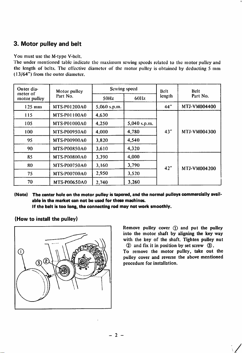
3.
Motor
You
The
pulley
must
use the M-typc V-belt.
under
mentioned table indicate tlie maximum sewing speeds related to tlie
and
belt
the length of belts. The elTective diameterofthe
(13/64")
Ou
meter
motor
from
the
outer
diameter.
5,060
4,630
4,250
4,000
3,820
3,610
3,390
3,160
2,950
2,740
Sewing
50Hz
s.p.m.
ler
125
115
105
100
95
90
85
80
75
70
dia
of
pulley
mm
Motor
pulley
Part
No.
MTS-P01200AO
MTS-POl
MTS-POIOOOAO
MTS-P00950AO
MTS-P00900A0
MTS-P00850A0
MTS-P00800A0
MTS-P00750A0
MTS-P00700A0
MTS-P00650A0
100
AO
motor
motor
pulley is obtained by deducting 5 mm
speed
5,040
4,780
4,540
4,320
4,000
3,790
3,520
3,260
60Hz
s.p.m.
Belt
length
44"
43"
42"
MTJ-VM004400
MTJ-VM004300
MTJ-VM004200
pulley and
Belt
Part
No.
(Note)
The
center
ableinthe
If
the
(Howtoinstall
holeonthe
market
beltistoo
the
can
long,
pulley)
motor
pulleyistapered,
notbeused
the
connecting
and
the
normal
pulleys
commercially
for
these
machines.
rod
may
not
work
smoothly.
Remove
into
with
the
the
pulley
cover 0
motor
shaft
keyofthe
and
by aligning the key way
shaft.
Tighten
(D and fix it in position by set screw (3).
To remove the
motor
pulley, take
pulley cover and reverse the above mentioned
procedure
- 2 -
for installation.
put
the
pulley
out
avail
pulley
nut
the
Page 6
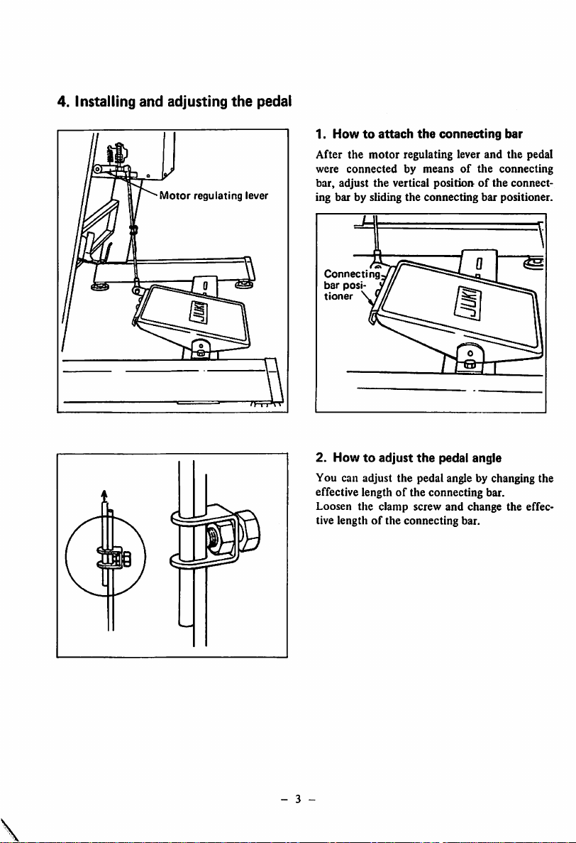
4. Installing
and
adjusting
Motor
regulating
the
lever
pedal
1.
Howtoattach
After
the
were
bar,
ing bar by sliding
Connecting
bar
tioner
2.
You can adjust
motor
connected
adjust
the
posi
Howtoadjust
the
connecting
regulating lever
by meansofthe
vertical
positionofthe
the
connecting
the
pedal angle
the
pedal angle by changing
and
bar
effective lengthofthe connecting bar.
Loosen
the
clamp
screw
and
tive length
of
the
connecting
change
bar.
bar
the
pedal
connecting
connect
positioner.
the
the
effec
- 3 -
Page 7
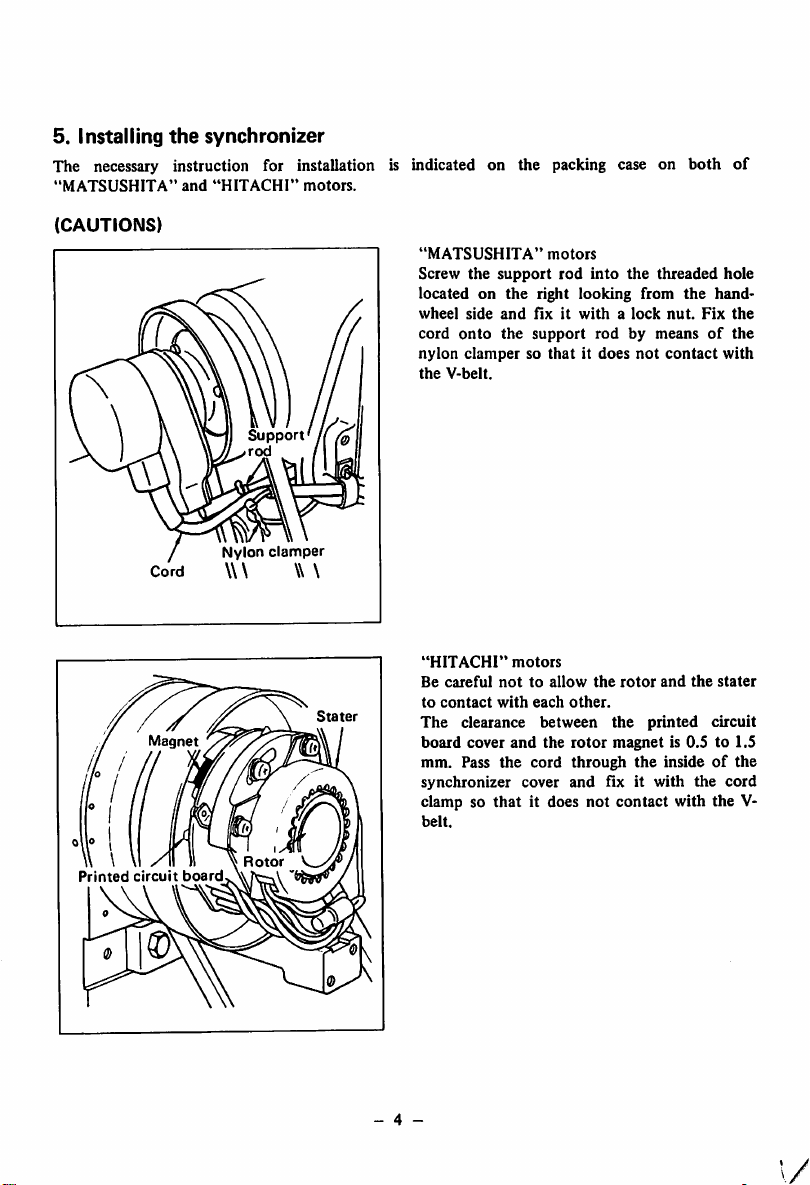
5.
Installing
the
synchronizer
The necessary instruction for installation is indicated on the packing case on both of
"MATSUSHITA"
and
"HITACHI"
motors.
(CAUTIONS)
Cord
Nylon
\\\
Support
rod
clamper
\\ \
"MATSUSHITA"
Screw
the
located on
wheel
side
cord
onto
nylon
clampersothat
the
V-belt.
motors
support
rod
the
right looking from
and
fixitwithalock
the
support
into
the
threaded
the
nut.
Fix
rodbymeansofthe
it does
not
contact
hole
hand-
the
with
Printed
Magnet
circuit
board
Rotor
Stater
- 4 -
"HITACHI"
Be
careful
to
contact
The
clearance
board
cover
mm. Pass
synchronizer
clamp so
belt.
that
motors
nottoallow
with
each
between
and
the
the
cord
cover
it does
the
other.
rotor
through
and
not
rotor
the
magnet
fix it
contact
and
printed
is 0.Sto1.5
the
insideofthe
with
with the V-
the
the
stater
circuit
cord
1/
Page 8
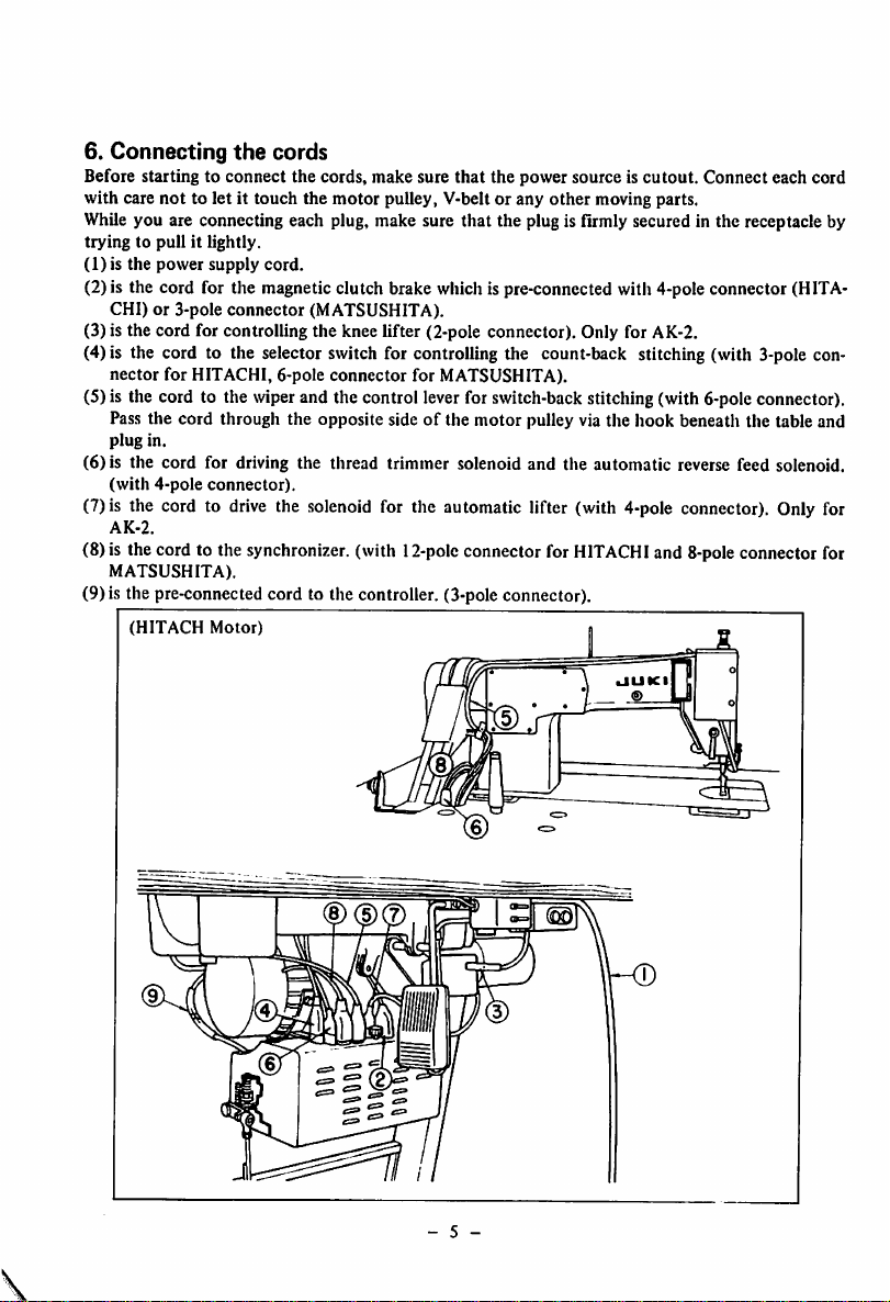
6.
Connecting
Before starting to connect the cords, make sure
the
cords
that
the power source is
cutout.
Connect each cord
with care not to let it touch the motor pulley, V-belt or any other moving parts.
While you are connecting each plug, make sure that the plug is firmly secured in the receptacle by
tryingtopull
(1) is the
power
it lightly.
supply
cord.
(2) is the cord for the magnetic clutch brake which is pre-connccted with 4-pole connector (HITA
CHI)or3-pole
(3) is the cord for controlling the knee lifter (2-pole connector). Only for AK-2.
connector
(MATSUSHITA).
(4) is the cord to the selector switch for controlling the count-back stitching (with 3-pole con
nector for HITACHI, 6-pole connector for MATSUSHITA).
(5) is the cord to the wiperand the control lever for switch-backstitching (with 6-poleconnector).
Pass the cord through the opposite sideofthe motor pulley via the hook beneath the table and
plug
in.
(6) is the cord for driving the thread trimmer solenoid and the automatic reverse feed solenoid,
(with
4-pole
(7)is the cord to
AK-2.
(8)is the cord to the synchronizer, (with
MATSUSHITA).
connector).
drive
the
solenoid
for the automatic lifter (with 4-pole connector). Only for
12-poIc
connector for
HITACHI
and 8-poleconnectorfor
(9) is the pre-connected cord to the controller. (3-pole connector).
(HITACH
Motor)
- 5 -
Page 9
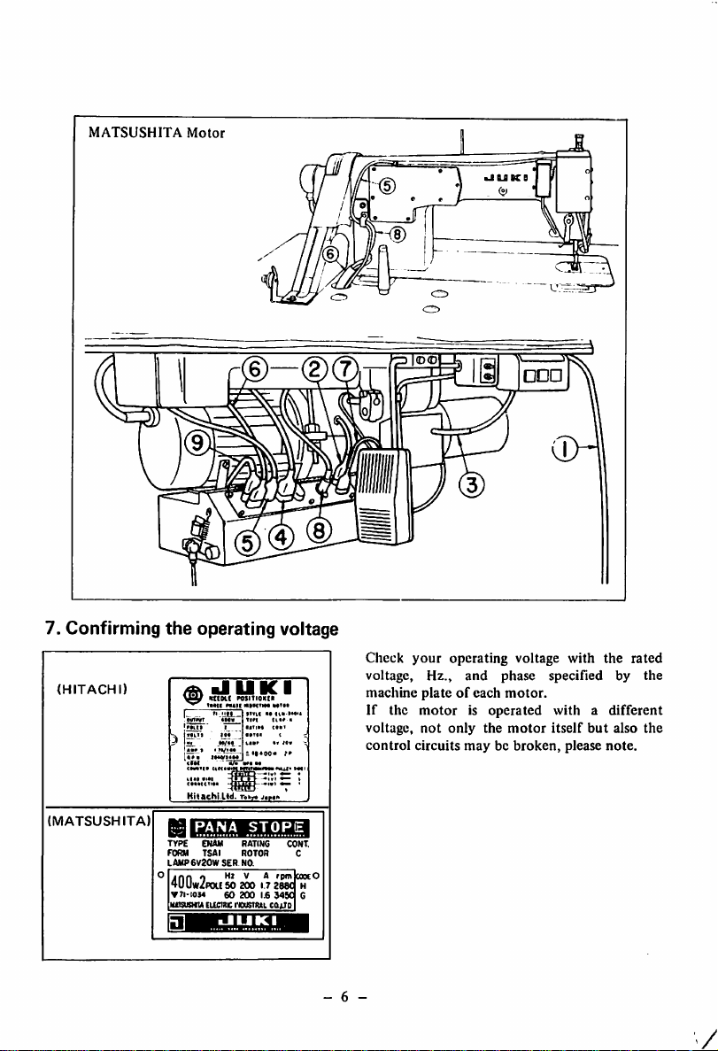
MATSUSHITA
Motor
>JUKB
I®®
7. Confirming
(HITACHI)
(MATSUSHITA)
the
operating voltage
HlOchi.Ud.
Totx
j.Mi
PANA
TYPE ENAM RATING CONT.
FORM TSAI ROTOR C
LAWP6V20WSER
jnn
4UUw/P0US0 200 17 2e8C H
•
n-i034
imsusTO
STORE
NO.
0 V A
60
200
Eiicwic
rcusTittL
•JUKI
rptnlcoocO
Ij6
34S0
cajjo
G
- 6 -
Clieck
voltage,
machine
If the
voltage,
control
your
operating voltage with the
Hz.,
and
plateofeach
phase
motor.
motorisoperated
not
only
the
circuits
motor
maybebroken,
specified
by
withadifferent
itself
but
also
please
note.
rated
the
the
V
Page 10
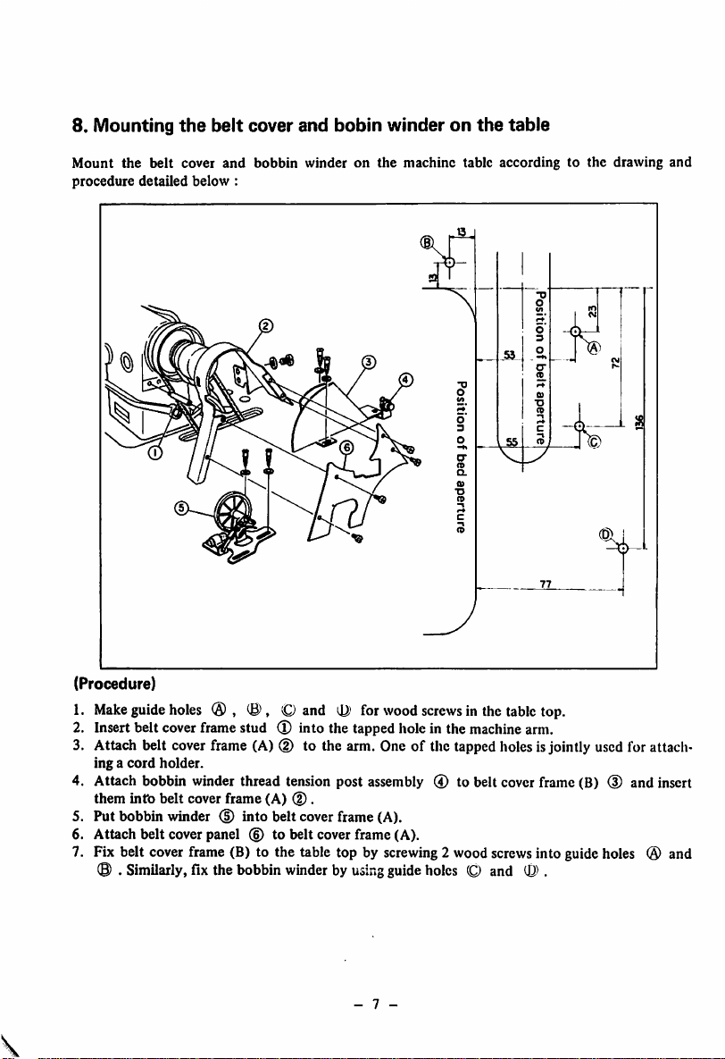
8. Mounting
Mount
the
procedure
belt
detailed
the
cover
below
belt
and
cover
:
bobbin
and
bobin
winderonthe
winderonthe
machine
table
table
accordingtothe
drawing
and
(Procedure)
1.
Make
guide
holes
® ® , O and for
2. Insert belt cover frame stud
(T)
into the tapped hole in the machinearm.
wood
screws
in the
table
top.
3. Attach belt coverframe (A) (D to the arm. One of the tappedholesisjointly usedfor attach
ing a
cord
holder.
4. Attach bobbin winder thread tension post assembly ® to belt cover frame (B) (D and insert
them
intb
belt cover frame (A)
5. Put bobbin winder (D into belt cover frame (A).
6.
Attach
belt
cover
panel
(D.
(6)tobelt
cover
frame
(A).
7. Fix belt cover frame (B) to the table top by screwing2wood screwsinto guide holes ® and
(8)
. Similarly, fix the bobbin winderby
using
guideholes (Q and .
- 7 -
Page 11
II.
1.
HOW
General
TO
OPERATE
instruction
THE
MACHINE
After the machine has been set up, bring down the needle by rotating the handwheel with
hand,
switchonthe
watching
from
the
the
open
machineontrial
and
rotationofthe handwheel.
sideofthe
handwheel.
check
The
that
the
handwheel
motor
must
rotatesinthe
rotate
correct
counterclockwise watching
direction
your
by
If you fail to judge it, you can repeat to switch on and off the machine until the direction is found,
o
Cleanupthe
installed
machine.
o Before starting to operate the machine, read through the separate INSTRUCTION BOOK,
o Do
not
drive
the
o Do
not
replace
machine
the
before
motor
pulley with a larger
the
oil
reservoir
one
is filled
with
within first 1
the
month.
lubricating
oil.
You may operate the machine at a higher speed depending on the necessityofsewing works
and operator's ability after the first 1 montli has passed,
o Keep away
o Do
tion or cleaning or removing
not
from
fail to
the
switch
needle
off
dropping
the
machine
the
V-belt.
place
before
when
you switch
you
tilt
the
the
machine
machine
head
on.
backwards
for
lubrica
(If you mistakenly tread on the pedal, the motor puUeywill be stopped immediately by means
of
the built-in safety device in the case of
you
move
the
o Whan
of
the
handwheel.
machinetoother
"HITACHI"
places, do
motor
not
hold it with
assembly.)
the
cover located on
the
rear
o Even if you tread on the pedal backwards (heel-down) immediately after the machine is switch
ed on or
the
thread
is trimmed,
the
needle
would
not
come
downorthe
thread
trimmer
would
not work. Such thread trimming motion is performed only after the pedal has been trod once
forwards
(toc-down).
- 8
Page 12
Oil
(Notes)
1. As
soonaslubricating
It
canbedrainedbyremoving
2. In
ordertothoroughly
at
a sewing
which
2.
Lubrication
speedof3,000to3,500
has
not
been
sight
and
window
oil
lubricate
operated
amount
has
become
the
oil
the
for
a long
of
dirty,
renew
drain
cap
machine,
s.p.m.
before
periodoftime.
oil
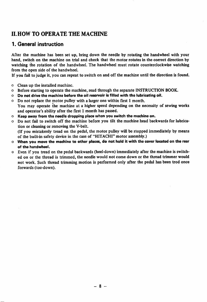
As long as the oil reservoir is properly filled up
with the lubricating oil, you will see the oil
splashingonthe
window
oil sight
lubricating oil is flowing or
have to
worry
ing in it.
the
oil.
screw.
provideitwithanidle
using a newly installed
while
window
internal
the
about
surfaceofthe
machine
is used
is running. Since
onlytocheckifthe
the
amountofoil
run
for
machineora
oU sight
not,
youdonot
appear
about10minutes
machine
the
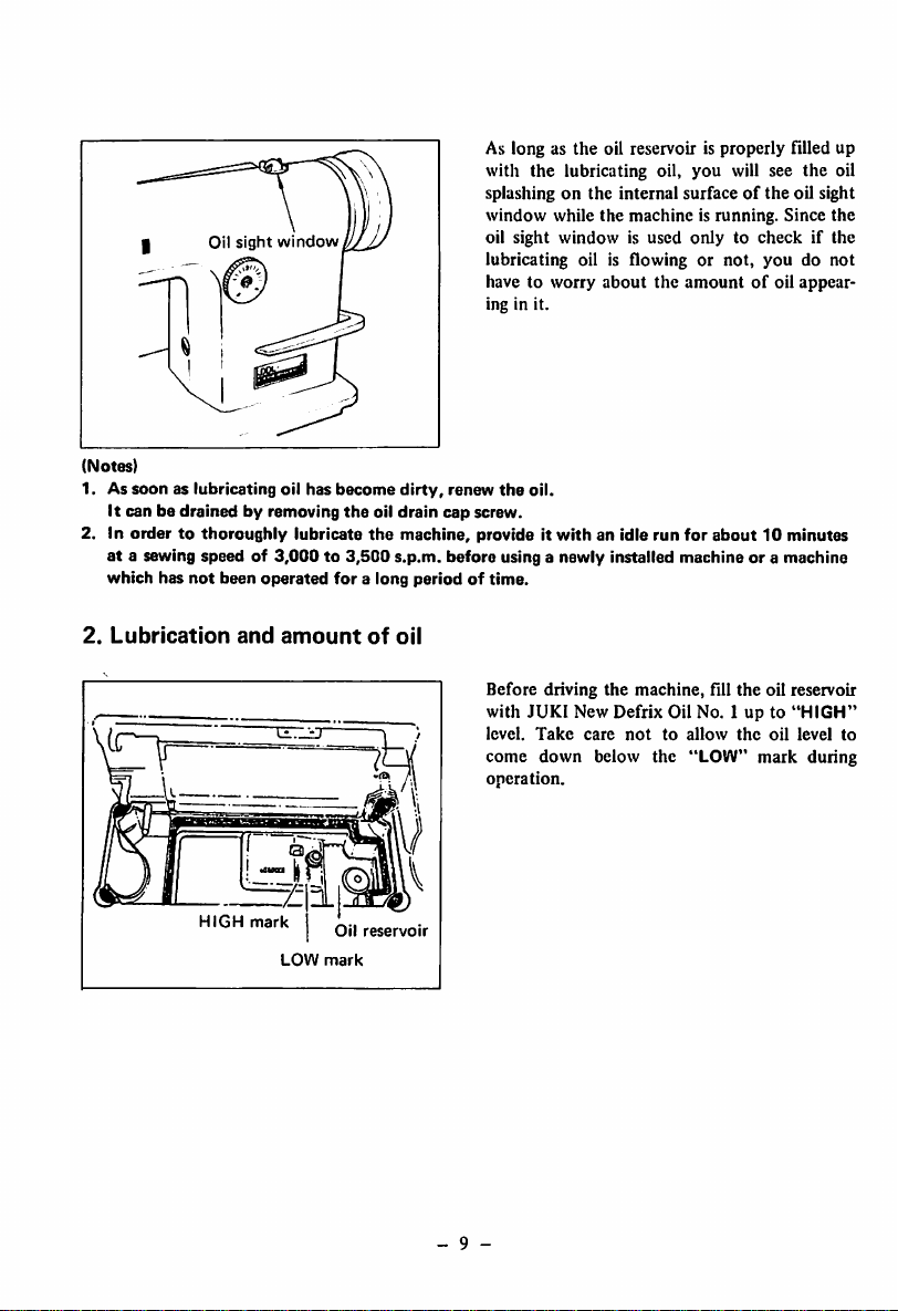
HIGH
mark
LOW
Oil
mark
reservoir
Before driving
with
JUKI
level.
Take
the
machine,
fill
the
New Defrix Oil No. 1 up to
care
nottoallow
the
come down below the "LOW" mark during
operation.
- 9 -
oil reservoir
"HIGH"
oil
level
to
Page 13
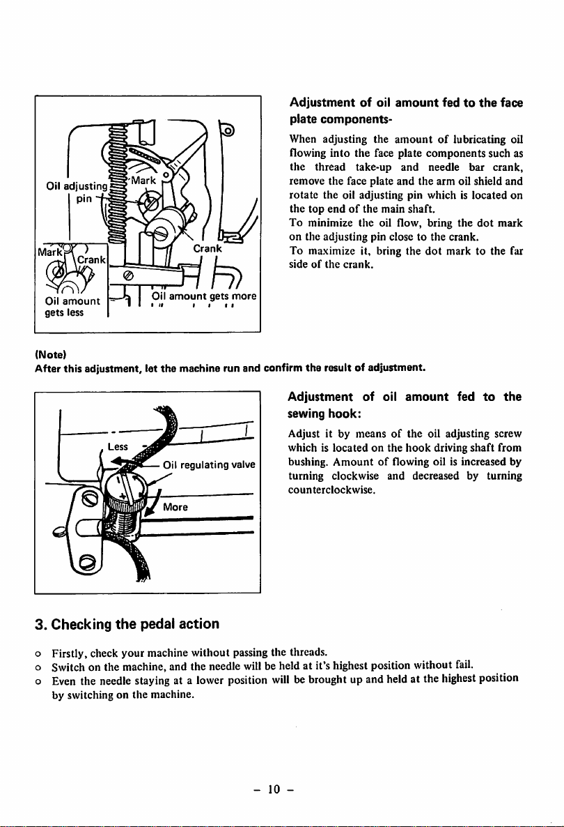
Mark
Oil
adjusting
pin
Crank
Mark
Crank
Adjustmentofoil
plate
components-
When adjusting the
flowing
into
the
thread
remove
the
rotate
the
face
the oil adjusting pin which is
top
endofthe
amount
fedtothe
amountoflubricating oil
the face plate components such as
take-up
plate
main
and
and
the
shaft.
needle
arm
oil
To minimize the oil flow, bring the
on the
adjusting
To ma.\imize it, bring the
sideofthe
crank.
pin close to
the
crank.
dot
mark to the far
bar
shield
located
dot
face
crank,
and
on
mark
r\
Oil
amount
gets
less
(Note)
After this adjustment, let
3.
Checking
the
amount
the
Oil
More
pedal
gets
I I
machine run and confirm
regulating
action
II
more
valve
the
result of adjustment.
Adjustment
sewing
Adjust it by
whichislocatedonthe
bushing.
of
oil
amount
hook:
meansofthe
Amountofflowing oil is increased by
oil adjusting screw
hook
turning clockwise and decreased by turning
counterclockwise.
Firstly, check your machine without passing the threads.
Switch on the machine, and the needle will be held at it's highest position without fail.
Even
the
needle
staying
at a
lower
by switching on the machine.
position
willbebrought
upand
held
at the
driving
highest
fed
to
shaft
position
the
from
-
10
-
Page 14
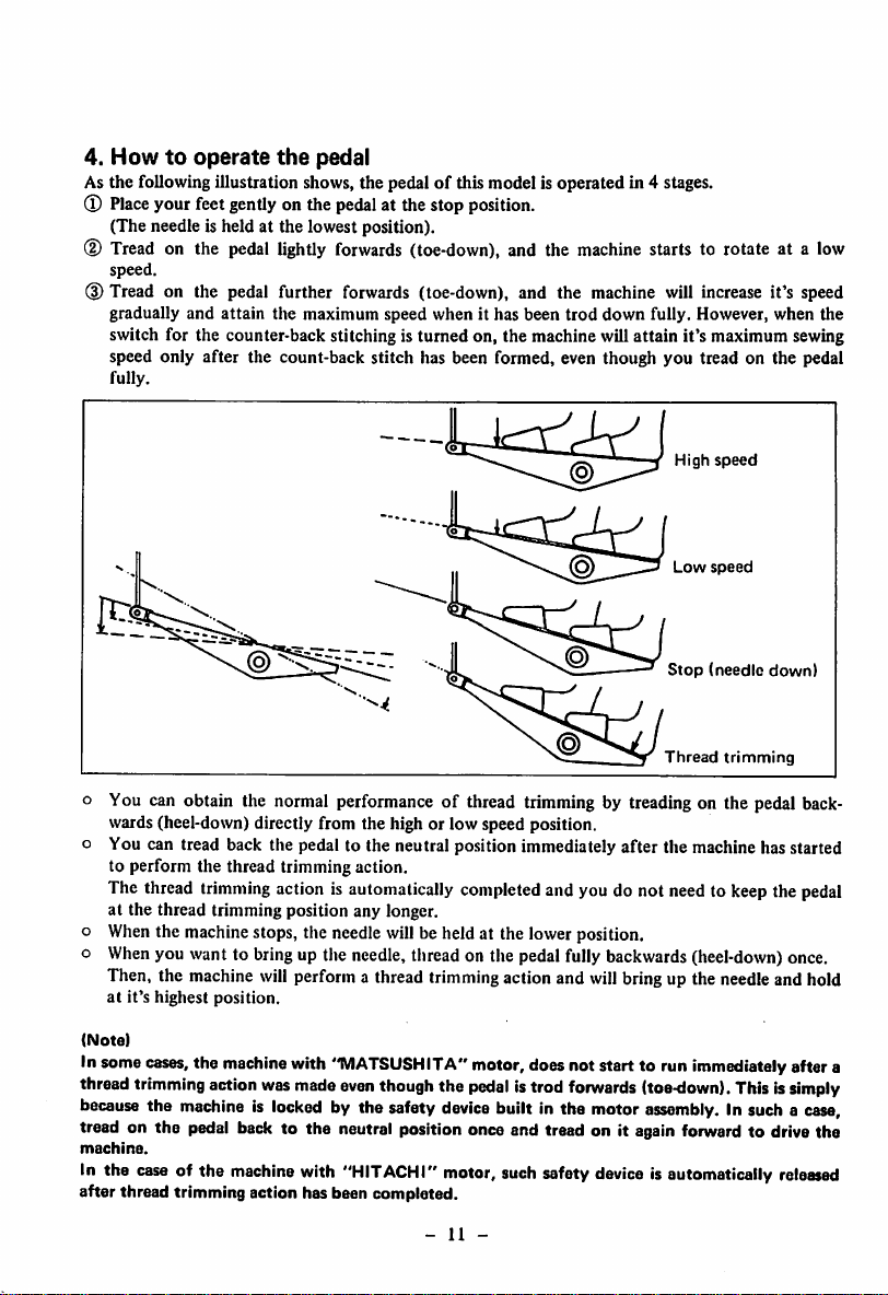
4.
Howtooperate
As the following illustration shows, the pedalofthis model is operated in 4 stages.
®
Place
your feetgentlyon the pedalat the stop position.
(The needle is held at the lowest position).
(D Tread on the pedal
speed.
(D Tread on the pedal further forwards (toe-down), and the machine will increase it's speed
gradually and attain the maximum speed when it has been
switch for the counter-back stitching is turned on, the machine will attain it's maximum sewing
speed only
fully.
after
the
pedal
lightly
forwards
the count-back stitch has been formed, even though you tread on the pedal
(toe-down), and the
machine
trod
starts to rotate at a low
down fully. However, when the
High
speed
Low
speed
Stop
(needle
Thread
trimming
down)
o You can obtain the normal performance of thread
wards (heel-down) directly from the high or low speed position,
o You can tread back the pedal to the neutral position immediately after the machine has started
to perform the thread trimming action.
The thread
at the thread trimming position any longer,
o
When
o
When
trimming
the machine stops, the needle willbe held at the lower position,
you want to bringup the
action is automatically completed and you do not needto keepthe
needle,
threadon the pedalfully
trimming
by treading on the pedal back
pedal
backwards
(heel-down)
once.
Then, the machine will perform a thread trimmingactionand willbringup the needleand hold
at
it's
highest position.
(Note)
Insome
cases,
the
machine
thread
trimming
because
tread on the pedal back to the neutral position once and tread on it again forward to drive the
machine.
In the
case
after thread trimming action has been completed.
action
the
machineislocked
of the
was
machine
with
"MATSUSHITA"
made
even
by the safety
with
"HITACHI"
thoughthe
device
motor,suchsafety
-
motor,does not start to run immediately after a
pedal
istrod
built in the motor
forwards
(toe-down).
assembly,
Thisis
in sucha
deviceisautomatically
11
-
simply
case,
released
Page 15

5. Adjusting
the
pedal pressure and stroke
(MATSUSHITA)
Adjustment
Adjustment
nutofthe
backward
pressure
spring.
C?
I Pedalpressure
^spring
grooves
(HITACHI)
Adjustmentofthe
Adjust the forward pressure by changing
positionofthe
"HITACHI"
The
pressure is
the
left
and
is increased to
"MATSUSHITA"
The
pressure is reduced by moving the spring
to the right
and
Adjustmentofthe
"HITACHI"
spring.
motor:
reduced
motor:
is increased to
motor;
forward
pressure
by moving tiie spring to
the
right.
the
left.
backward pressure
the
The backward pressure can be adjusted by
means of the adjustment nut of the backward
pressure spring. The pressure is increased by
tightening the spring and reduced by loosening.
(MATSUSHITA)
Motor
regulating
Connecting
(u
lever
(HITACHI)
rod
Adjustmentofthe
pedal
stroke
The pedal stroke can be adjusted by changing
the
with the
"HITACHI"
The
with
creased by the right
"MATSUSHITA"
The
with the right hand
increased by
-
12
-
connectionofthe
motor
regulating lever.
motor:
stroke is reduced by connecting
the
left
hand
stroke is reduced by connecting the rod
the
sideofthe
hand
motor:
left
hand
upper
side.
.side
of the lever and is
side.
connecting rod
the
lever
rod
and
in
Page 16

6. Automatic count-back stitching
You
can
form
the
count-back
without
operationofthe feed
Count-back
at
Count-back
at
BACK
TAG SW.
START
0FF|^^l6iA
END(»*')
)
OFF^^-SiT
•JUKI
(Note)
When the selector switch for the automatic count-back stitching is not used (with a
motor): Disconnect the swjtch from the motor control box.
When
it is
used,
insertaconnector
( 4 ,
Fig.
paragraph
5)on the motorcontrolbox.
stitches
control
the
the
Selector
formingacount-
back
startofa
Selector
formingacount-
back
endofa
stitch
start.
stitch
end.
switch
stitchatthe
seam
switch
stitchatthe
seam
J
whichiswiredasillustrated
at the start and/or the end of a
lever or switch-back lever.
(T)
You can preset the machine to form the
count-back
endofthe
lector
switches.
(D If the numberofcount-back stitch is
enough for your sewing purpose, turn
the selector switch and produce the neces
sary length of reverse stitches manually by
making usofthe
or
the
switch-back
(3) When the selector switch for
turned
on,
automatically
ately by treading on the pedal backwards
before or after forming the count-back
stitchatthe
tiiough you tread on the pedal for thread
for
line.
for
line.
trimming while the count-back
being formed, the thread trimming action
will not be performed prior to the forma
tionofthe
said
® When the selector switch for
turned on, the thread trimming action will
be
performed
been
formedatthe
you tread on the pedal for thread trimming
while the machine is forming a count-back
stitch at the endofa
will trim off the thread after completing the
said
count-back
below
(Option.
PartNo.
seam
line
stitches at
seam
you
trim
startofa
count-back
after
the
line by
reverse feed
lever.
can
let
off
the
the
count-back
endofa
.seam
stitch.
intothe
position
D6010555DA0)
start
meansofthe
the
thread
seam
stitch.
line, the machine
automatically
and/or
the
not
off
control
lever
"Start"
machine
immedi
line.
Even
stitch
"End"
stitch
has
seam
line.
HITACHI
of 3-p
plug
se
is
to
is
is
If
A
O
o
o
13
Page 17

7. Passing
o ir the machine stops leaving the needle at a lower position, tread on the pedal backwards for
performing an idle thread trimming before passing the needle thread.
Then,
o Pass the needle thread in the
the
needle
the
needle will go up
thread
and
order
stayatthe
highest
from ® to ® as shown in the illustration.
position,
I
-
14
-
Page 18

8.
Bobbin
thread
Bobbin
Adjustment
—Thread
case
screw
Tension
screw
Thread
post
bracket
hole
Thread
passing
Hook
tension
hole
Inserting
1. Bring up
2.
3.
4.
Winding
1.
2. Push
3. Adjust the winding adjustment screw so
and
removing
the
needle to its highest
by
manually
Tilt
rest
table.
Liftupthe
the
bobbin
Bobbin will
latchislifted.
To
insert
into
the
on
tiic
rotating
machine
the
bobbin
case.
not
the
hook
the
head
rubber
pads
case
fall
bobbin
shaftsothat
down
bobbin case rests in tlic
close
the
latch.
the
bobbin:
Thread
the
bobbin
winderinthe
illustrated
times
bobbin
the
about
and
wind
round
the
the
bobbin.
bobbin
down
winder pulley
threadiswound
80 per
centofits capacity.
the
touch
round
the
bobbin
handwheel.
back
and
allowitto
attachedtothe
latch
and
as long as the
case, fully
the
noseofthe
hook
groove
thread
end
trip latch to let
the
belt.
the
bobbin
case:
position
take
out
insert
and
order
several
the
that
for
4. When the bobbin is wound unevenly,
correct it by moving the thread tension post
bracket.
Tighten the screw for increasing the thread
length
to be
wound
and
loosen
for
reduce.
5. As soon as the
bobbin
in filled, the bobbin
winder will automatically stop.
(Note)
In order not to wound
withasynthetic
screw so
thr
inserting
1.
thread
Take
that
the
tension
the
bobbin
the
bobbininyour
thread,
thread
post
the
is lightly
socket,
into
bobbin
adjust
the
bobbin
handsothat
too
the
drawn
tight
tension
from
case:
the thread is directed clockwise and place it
into
the
bobbin
the
slotinthe
case.
fingers
bobbin
and pull up
case.
2. Take the thread in your
toward
3. Pull the thread, and it will pass through the
thread tension spring.
""Make
sure that the bobbin spins in the
bobbin
the
caseinthe
arrow
when
direction
the
threadisdrawn.
indicated
with
it
as
-
15
Page 19

9. Adjusting
Decreased
the
thread
Decreased
V\S—Increased
tension
Thread
Increased
Thread
No.
No.
tension
1
tension
2
Needle
thread
tension:
Needle thread tension is adjusted by the thread
tension
nuts
No. 1
and
No, 2
thread
tension
increased by a clockwise turn and reduced by a
counter-clockwise
o
Thread
tension
turn,
No.
1.
The length of needle thread remaining in the
needle
after
when
the
thread
tension
nut
No. 1 is
ened, and vice versa. Tighten the tension
thread trimming becomes
whenathin
used
used.
o
Thread
thread
like
and
loosenitwhenathick
tension
No.
2
synthetic
short
tight
nut
thread
thread
Adjust the thread tension nut No. 2 so that
the
needle
and
bobbin
threads
are
inter-
looped in the middle of the material. Do not
excessively reduce the thread tension when
sewing with a synthetic thread, or the
thread may be broken at the start of sewing.
is
is
is
thread
take-up
spring
Moving
range
Thread
tension
bar
(Note)
Thread
Thread
set
Tension
set
screw
screw
take-up
tension
bracket
bar
Thread
tension
socket
spring
When using a thin cotton or synthetic thread,
excessive
tensionorstroke.
Otherwise, stitch may be skipped at the end of
Thread
take-up
spring
Adjust the thread take-up spring for the follow
ing
standard:
Thread
Cotton
Cotton
Synthetic
Thread
No.
#40orless
#50ormore
Stroke
7to10
mm
(9/32"
to 25/64")
6to9
mm
(15/64" to 23/64")
6to9
mm
(15/64"
to 23/64")
o To change the stroke of the thread take-up
spring, loosen the screw of the thread
tension post socket and turn the thread
tension post in either direction,
o To change the tension of the thread
spring, loosen the screw of the thread
tension post socket, remove the thread
tension post and adjust the tension after
loosening
the
set
screw.
Tension is increased by turning the thread
tension post in the clockwise direction, and
vice
versa.
take
care not to provide
the
take-up spring with an
sewing and the threads will not be trimmed.
-
16
-
Tension
20 to 35g
15 to 30g
7 to 20g
tate-up
Page 20

Howto adjust the thread length remaining in the needle after thread trimming:
o In order to prevent the needle thread from slipping
. face of the materialat the start of
sewing,
a proper length of needlethreadmust beleft in the
needle eye after thread trimming.
o The thread length is adjusted by the thread tension No. 1.
o It is possible to provide the thread trimmer with different timing of action to trim a synthetic
thread from that of cotton thread. Consult withour distributorsor agentsin your areafor this
modification.
0
1
o
off
and produce neat stitch on the bottom
Increased
Adjusting
10.
Attaching
Use
a proper size of
screw
the
material as listed below;
Needle
#9
11
14
X 1
xl
16
18
21
22.23
8-9
11
14
DB
DA
Reduced
needle
DB,\1
or DAxl needle according to the
Thread
Cotlon
#80
80-60
60-50
30-20
30-
8
80
60
50
Synthetic
#80
80-60
60-50
50-30
30-20
8
80
60
50
Bobbin
Bobbin
tightening or loosening
bobbin
thread
tension:
thread
tension can be adjusted by
the
case.
Turn
tension screwofthe
the
screw
clockwise
increasing and counterclockwise for reducing
the
bobbin
thread
tension.
Fine
Light-weight
General
cloth
thickness and
Georgette, nylon,
broadcloth
Broadcloth, light-weight knits
Cotton
typeofthread
Material
gabardine,
tetron
drill
Medium-weight Coatings
Heavy-weight
Extra-heavy
Extra-heavy
Fine
Light-weight
General
cloth
Denim
Cantton,
Cantton,
canvas
canvas
Georgette, nylon,
broadcloth
Broadcloth,
Cotton
fine
gabardine, drill
tetron
knits
for
and
-
17
-
Page 21

11.
Needle
Presser
foot
Screw
Adjusting!
screw
Groove
Let the needle bar go up to its highest position
by the handwheel. Loosen the needle clamp
hold
screw,
right, insert the needle
a needle facing its recess to the
into
the needle clamp as
far as it will go and tighten the needle clamp
screw.
Adjusting
the
presser
foot
pressure:
Pressure applied by the presser foot to the
works is increased by rotating the presser spring
regulator in the clockwise direction and vice
versa. It is
when
Tighten the lock
advisabletoset
general
cloth
is sewn.
nut
after adjusting the presser
it to
about
5 Kg
spring regulator.
Hand
lifter
Presser
lifter:
Turn the hand lifting lever located in the rear of
the
machine
the
presser foot will go up for
(13/64")
Push
down
come
from
down
head
hand
to press
eithertoleft
the
throat
lifter,
plate
and
the pre.sser
the
work. By the knee
lifter, the presser foot will go up for
10 mm
(25/64")
-
18
-
from
the
throat
or right,
about
surface.
foot
plate surface.
and
5 mm
will
about
Page 22

12.
Stitch
13.
length
Stitch
adjustment
length
Reverse stitching by using
N
Feed
control
I
Stitch length is adjusted by the stitch dial
located
above
the
reverse
feed
control
lever.
Set a desired
the pointer pin fi.xcd to the machine arm.
*The ma.ximumstitch length is 4 mm (5/32").
stitch
length
(mm)ofthe
dial to
E
the
reverse feed
Push
as a
Release
lever
immediately
forward
/
down
desired
your
direction.
control
the
reverse
reverse
hand
go up to feed
lever
feed
control
stitchiscompleted.
from
the
lever,
the
material in
lever as
and
long
it will
the
OOL-SBS-4
19
-
Page 23

III.
ADJUSTMENT
1.
Feed
mechanism
Thrust
Set
screw
collar
\Feed
eccentric
n
drive
\ II
cam
w
Adjusting
the
feed
timing:
(excepting DDL-555H-4):
To
obtain
the
standard
feed timing, align
the
engraved line on the feed drive eccentric cam
with
the
dot
markonthe
adjustment,
and
stitches
puckering
will
haveanideal
Loosen 2 setscrewsonthe
thrust
stitch
will be eliminated
thread
feed drive
collar.Bythis
tension.
eccentric
cam properly position the cam and firmly
tighten 2 setscrews.
mm
If
it is preferable to
nism
with
an earlier
timing in
ping
eccentric
arrow.
ordertoprevent
during
stitching,
caminthe
Feed
Feed
Needle
dog
provide
timing
move
direction
Needle
dog
mm(
Throat
the feed
than
the
the
work
the feed drive
shownbythe
Throat
mecha
standard
from
plate
plate
slip
If
it is necessary to delay the timingoffeed
mechanism in
sioninstitches,
caminthe
do
not
becomeacauseofneedle
-
20
-
order
move
direction
moveittoo
Feed
to improve
the
feed
shownbythe
much,
otherwiseitmay
breakage.
Needle
dog
the
drive
Throat
thread
eccentric
arrow.
ten
But,
plate
Page 24

Front
Screw
(Note)
The
heightofthe
up
driver
Standard
DotL_^
Set
feed
Front
screw
dog
mustbecorrected
down
Adjusting
the
feed
dog
Inclination
(excepting DDL-555H-4):
The
feed dog
adjustedtohorizontal
tion). It can be changed, if necessary, according
to
the
varied sewing
o
Descent
Puckering is
is easily
o
Ascent
Cloth
fabric
o The standard inclinationofthe feed dog is
that
the
is aligned
Loosen
insertascrew
the
feed
direction. The front top of the feed dog will
be raised to
shaftisturned
by an
every
time
after
of
each
machine has been
position
(front-up)
comming
(front-down)
slipping
texture
arrow,
changing
conditions,
position:
prevented
out.
and
and
position:
breakage
chain-off
arc prevented,
engraved
with
2 setscrewsofthe feed bar
dot
on the feed bar
the axesof2 setscrews.
driver
bar
the
and
blade
shaft
and
turn
highest position when the
90"inthe
vice versa.
its
inclination.
into
direction
(standard
thread
of
knitted
the
slot
90"ineither
shown
posi
shaft
shaft,
in
•
Feed
H
driving
ri"
fork
,^CIamp
screw^
Adjusting
the
feed
dog
height:
The standard heightofthe feed dog is to Jut
out
its
teeth
0.8 mm
(1/32")
plate surface when sewing general materials. It
is advisable to change the feed dog height to
about 0.6 mm (1/64") for sewinglight-weight
materials
weight
If
the
occurred.
Loosen
crank, set
securely
-
21
-
and
about
materials.
1.0 mm
the
feed dog
throat
teeth
plate surface, puckering seam may be
the
setscrewofthe
the
feed bar for a
tighten
the
setscrew.
Feed
dog
Juts
(3/64")
out
proper
0.8mm
j/^c
feed
above the
too
much
rocker
position
Throat
throat
for heavy
above
shaft
and
plate
Page 25

2. Replacing
qpt
bet
Feed
base
lT0
the
sewing
«rrpw
Bobbincase positioning
screw f ,
hook
,.
Hook
When
the
sewing
hook
new
one
duetosome
following
1.
2.
3.
Set
screw
4. Loosen 2 sewing
5.
6.
7. Pull
procedure;
Manually
needle
reaches
Remove
Loosen
holder
the
positioning
positioning
Manually
feed
bar
Rotate
hold
reaches its highest position.
the
it in
out
the
turn
the
finger.
rotate
sewing
the
"'When installing
above
procedure.
has to be replaced with
reasons,
the
handwheel
its
highest
position.
bobbin
case
setscrew
and
of
finger
hook
screws.
the
handwheel
hookbyyour
position
sewing
the
hook
sewing
as illustrated.
to the left.
removeitin
until
the
needle.
the
bobbin
and
remove
until
finger
hook,
reverse
the
the
case
the
the
and
the
22
Page 26

3.
Sewing
hook
position relatedtothe
Clamp
screw
needle
Adjust the sewing hook position related to the
needle in
1. Bring up the needle to its lowest position by
2.
the
handwheel.
Loosen
tion.
the
following way :
the
screwofthe
needle
bar
connec
Blade
the
hook
Needle
point
sewing
(Needle
^
^
^
•
>
Needle
lower
Upper
indicating
Lower
line
Needle
bar
bushing
line
indicating
bar
3
4.
(Sewing
5.
Lower
indicating
(At
this
position,
the
blade
^ sewing hook with
of
line
match
pointofthe
the
center
the
needle)
Sewing
hook
of
6. Mold by
7.
8. By
9. Do
10.
bar
height)
Align
the
bar
lower
Tighten
Loosen
hook.
upper
with
the
bottom
bushing.
the
needle
hook
position)
2 .setscrews to release
hand
taking-up
Rotate
position.
the
handwheel
engraved line
the
bottom
end
bushing.
keeping
the needle bar in
mention-position,
of
the
sewing
hook
not
keep
away
the
more
tighten
liook
needle.
Securely
engraved lineofthe needle
the
of
endofthe
bar
connection
sewing
the
needle bar reaches
of
the
needle
the
hookinthe
until
the
needle
bar
screw.
sewing
the
align
the
pointed
with
the
needle
axes.
pointed
the
than
sewing
endofthe
O.OSmmfrom
hook
sewing
screws.
bar
thread
lower
lower
above
end
the
-
23
-
Page 27

4. Heightofthe
presser
Presser
screw
bar
bar
clamp
When correcting the height or angleofthe
presser bar after replacing the presser
some
other
reasons,
from the face plate
remove
and
the
loosen the screwofthe
rubber
foot
or
plug
presser bar guide bracket by inserting a screw
driver through the opening in the face plate.
Securely tighten the screw after adjusting the
^
presser bar height.
Howtouse
the
pressure
reducer:
It is possible to sliglitly reduce the pressure
applied by the presser foot when the pressure
reducer is used. This system is
when a floating presser
hastobe
continue
turned
to
stitch
Loosen the lock
foot
roundatan
inadifferent
nut
(g)
and
quite
useful
is used or a work
endofa
seam
direction.
properly tighten
the adjusting screw (g) , and the presser foot
will be raised up from the
so
that
the
turned
material
round
easily
the
throat
in
the
needle.
plate surface,
machine
can
to
be
-
24
-
Page 28

5.
Thread
take-up
action
6.
Returning
Thread
guide
(A)
pressureofthe
Increased
Reduced
reverse
It is recommendable to change
up
action
stitch
crease
according to
length, in
stitches.
the
thread
length
and
tightened
o When sewing heavy-weight materials, in
the
thread
the
typesofmaterial
ordertoobtain
takenbythe
take-up lever by lowering the thread guide
(A).
o When sewing light-weight materials,
the tliread length taken by the thread
take-up
lever by positioning
the
guide (A) in the middle or higher place.
This adjustment can be made after loosening
the
setscrewofthe
feed
control
In
ordertoallow
to
immediately
after
the
lever is forced
is necessary to
use
the
being released in
machine
thread
lever
the
reverse
return
back
reduce
at a low sewing
guide (A).
to its
any
by a
the
feed
stanby
sewing
strong
returning
speedorwith
control
conditions,
spring.Ifit
pressure to
fine stitch, slightly loosen the adjusting nut
take-
well-
thread
reduce
thread
lever
position
a
®.
-
25
-
Page 29

7. Adjusting
the
needle
stop
position
after
thread
trimming
You can adjust Hieposition at which the needle stops after a thread trimming has been completed.
The
standard needle
hand
wheel
with
the
stop
position is shown by the coincidenceofthe white
red
dodonthe
machine
arm.
This
adjustment
can be
dot
made
marked on the
by changing
the
installation angle of the sensing elementofthe synchronizer component. Refer to the separate
Instruction Book prepared for the
Stater
\
motor
assembly for the detailsofadjustment.
flange
"HITACHI"
Remove
the
component and adjust the installation angle
motor;
cover
from
the
synchronizer
of the printed circuit board within the adjust
able range of the oval holes on the stater flange.
White
Red
dot
Printed
circuit
board
cover
Magnetic
"MATSUSHITA"
Remove
the
cover
motor:
from
the
synchronizer
adjust the installation angle of the magnetic
plate.
-
26
-
and
Page 30

8.
Sharpening
Horn
Sharpen
Blade
1 /
this
this
the
corner
face-./
tip"""^^
N
counter
knife
y
^
As
soonasyou
trimmer has become dull, resharpen the
counter
knife
Put
the
resharpened
\
it's correct position shown by the following
illustration.
If you move the installing positionofthe
counter
knife to the right from the standard
noticed
immediately.
counter
that
knife
the
thread
back
to
position, the length of thread remaining on
the needle
and
vice
versa.
after
trimming becomes longer
Needle
Moving
center-
"*
knife
a
Counter
Shorter
I
The
of
knife
the
remaining
thread
becomes;
length
—
Counter
Longer*
I .omm
Stepped
of
the
Bottom
the
part
bed
knife
throat
face
plate
of
-
27
-
Page 31

IV.
HOW
TO
1.
Adjusting
ADJUST
the
positionofthe
THE
WIPER
wiper
You must adjust the position of the wiper according to the thickness of the material to be sewn in
the
following
way;
1)
Rotate
normal direction so
on
r
the
(D on
the
handwheel
handwheel
the
frame.
that
coincide
manually in
the white
with
the
dot
red
dot
2) Insert the wiper (D into the wiper driving
shaft
(2) so
that
the
vertical
clearance
between the wiper edge and the needle
point becomes 2 mm and also the parallel
clearance
straight inside faceofthe
between
the
needle
wiper becomes
center
and
1 mm. Fix the wiper at such a position by
tighteningthe lock nut (3) .
the
(D
the
2. Adjust
Wiper
the
positionofthe
switch
wiper magnet
Pull the plunger fully into the coil, loosen the
screw 0 which is clamping the wiper magnet
and
that
of2mm
Afteracorrect
the
the screw. When
off
28
—
adjust
the
positionofthe
wiper magnet so
the wiper tip is positioned with a clearance
from
the
center
wiper magnet at
position
the
wiper
switch.
lineofthe
has
that
position by tightening
youdonot
been
use
needle.
obtained,
the
wiper,
fix
turn
Page 32

V.HOW
1.
Forming
2.
Adjusting
I
TO
USE
AND
the
switch-back
the
positionofthe
ij
ADJUST
Swi
tch-back
button
f
THE
stitches
switch-back
DK Tighten the
SWITCH-BACK
Push
tiie
machine
form
the
As long as the
machine
As
soon
machine
When
you
reverse
feed
switch-back
will
perform
switch
back
buttoniskept
will
perform
as
the
will
reversedtothe
sew
control
BUTTON
button,
a reverse
stitches.
the reverse feed.
button
the
half
lever.
pressed,
is
released,
normal
stitches,
and
feed
feed.
use
lever
You
may
change
the
back buttonC1to a suitable height for your
positionofthe
operation.
Loosen
the
screw
(2) ,
move
the
up
and
down
and
obtainasuitable
screw
firmlyafter adjustment.
switch
switch
lever
height.
the
to
the
the
the
3.
Adjusting
the
reverse
stitch
length
-
An excessive lengthofreverse
formed by the
operate
be
advisable
reverse feed by decreasing the stitch length of
reverse feed in
length
with
To
lessen
this
new
the
the
operator
device.Insuchacase,itwould
to
shorten
comparison
normal
lengthofthe
stitch
until he gets used to
the
seam
line
with
feed, if it is permissible.
reverse
stitch,
the screw (I) and push up the stopper plate
d).
If you push it down to the normal and
reverse
feeds
are
identical.
29
-
is usually
with
the
stitch
loosen
the
Page 33

VI. AUTOMATIC PRESSER FOOT LIFTER, AK-2(Optional attachment)
The automatic presser foot lifter
AK-2
is an optional attachment which is capable of lifting the
presser foot and holding it at the heighest position for 10 to 15 secondsafter thread trimming has
been
made.
A special
1.
Howtooperate
motor
is used
AK-2
for
this
lifter
AK-2.
If you want to raise the presser foot during a
sewing
work,
presser
diately
foot
after
press the knee
will be
the
knee
switch.
Such
comming
switchisreleased.
down
raised
imme
If you want to bring down the presser foot
which
has
been
raisedasthe
resultofan
auto
matic run, tread on the pedal forwards (toe-
Knee
switch
2.
Adjusting
Coupler
the
presser lifter
stroke
down)orpush
1. Loosen the lock
2. Lower the presser foot
by
3.
Push
loosening
the
knee
and
release
nutofthe coupler.
the
lock
nut.
switchtodrive
the
knee
stopper
the
switch.
(A) fully
solenoid.
4. You can adjust the strokeofthe presser
foot by rotating the plunger on the far side
of
the
8.
Loosen
your
end/of
become
the
hand
the
about
solenoid;
a clockwise
counterlockwise
(The
maximum
presser
5. Raise
footisabout8mm
stopper
servoir by activating
6. Raise the
half
turn
7. Tighten
the
(B) so
connecting
the
coupler
presser
the
lifter
that
Presser
lifter
stopper
Presser
Stopper(A)
lifter
V
lever
Presser
tM\li
lock
nutofthe
and
adjust the heightofthe
knee
lifter
rod
Plunger
(B)
lifter
stopper
and
the
(B),
knee
push
stopper
lifter
1 mm (3/64"). After obtaining a proper position, retighten each lock nut.
the
stroke
turn
and
is decreased by a
turn.
stroke
performed
(A)
untilithits
the
stopper
after
lock
releasing
solenoid.
(A) by rotating it
the
nutsofthe
respectively.
lever
towards
the
playing gap between the
rod
locatedonthe
is increased by
by
(5/16")).
the
another
knee switch.
stopper
(A) and
the
solenoid
machine
oil re
with
head
the
top
-
30
-
Page 34

VII.
TROUBLES
AND
CORRECTIVE
MEASURE
Troubles
1.
Thread
breakage
2.
Stitch
skipping
Causes
1)
Thread
qualityispoor.
2)
Threadistoo
needle
3)
Threadisbrokenbythe
heatofthe
4)
Thread
5)
Thread
hook,
discs,
components
burrs.
thick
size.
needle.
tensionistoo
pathonthe
throat
plate,
thread
take-uporother
has
scratches
6) Stitches are skipping.
7)
Bobbin
thread
low.
8)
The
needle
facetothe
1) Distance
hook
blade
is
not
2) Needle bar height is
3)
4)
5)
6)
7)
correct.
correct.
Needleisbent.
Needle
plateistoo
Needle
footistoo
Thread
needle.
Thread
tensionistoo
recess
correct
from
the .sewing
from
holeinthe
great.
slotinthe
great.
clings to
tension
does
the
the
No.
high.
8) Presser
9)
sufficient
works.
Bobbin
low.
foot
does
pressuretothe
thread
tensionistoo
not
for
high.
sewing
tension
not
direction.
needle
not
throat
presser
heated
1 is
give a
the
too
Corrective
o
o
o
Use
the
quality.
Correct
thread
Prevent
measures
threadofbetter
the
and
the
over-heating
thread).
o
Reduce
o
or
o Provide the sewing
o
o
o
o Align the engraved lineofthe
o
o Bring
n Bring
o
o
o
o
the
Remove
such
burrs
from
by using an
or replace
parts.
blade
from
timing.
Hn.sure the needle bar height.
Adjust
between
bobbin
Insert
rect
Correct
timingofthe .sewing
relatedtothe
needle
endofthe
bushing.
Replace
the
withaproper
the
needle
the
the
threads.
the
needleinthe
way.
the
bar
with
the
down
and
increa.sc
stroke
(it
weight
increase the .sewing
stroke.
Prevent
heating.
Reduce
turning
tension
Increase
pressure.
Increa.se
tension.
occurs
materials).
down
the
the
counter-clockwi.se
nut
the
the
combination
needle.
needle
from
(synthetic
thread
tension.
scratches
the
oilstoneorbuff.
defective
thread
or
path
hook
clearance
andacorrect
thread
tension
needle
and
cor
clearance
needle
needle.
the
bar
and
hook
bottom
lower
needle.
the
needle
sewing
in light
needle
bar
hook
bar
the
the
hook
needle
from
thread
ten.sion by
No.
1.
presser
bar
bobbin
thread
of
over
and
the
Page
17
16
23
17
17
23
23
16
18
17
- 31 -
Page 35

Troubles
Causes
Corrective
measures
Page
3.
Isolated
idling-
loops
("Baloonstitch")
4, Wobbling
or waving
stitches.
S.
Idle
stitching.
6.
Loose
stitch.
I) Sewing
2) Adjust
3)
4) Feed dog
5)
6)
7)
1)
2)
3)
4)
5) Needle bar
1) Inclinationofthe
2)
3) Positionofthe
4)
1)
2)
3)
4) Thread take-up lever excessive
5)
6) Feed dog
7)
8)
hook
the
sewing
Needleistoo
out
plate
Presser
Needle
too
Tensionofthe
up spring is
Bobbin
too
Needleistoo
Threadistoo
The
not
tion.
teeth
enough from the
surface.
footisnot
thread
low.
not
thread
high.
recessofthe
facetothe
thread
not
proper.
is
Presser
footisnot
not
proper.
Thread
tensions
proper.
Needle
thread
too
low.
Bobbin
thread
too
high.
Threadistoo
needle.
ly takes up
Feed
out
plate
Thread
pass
throat
thread
paths.
Tensionofthe
spring is
the
timingistoo
teeth
enough
from
surface.
does
through
plate, tension discs.
take-uporother
not
is defective.
hook.
thin.
does
not
throat
suitable.
tension
thread
enough.
tension
thin.
thick.
needle
correct
guide.
feed dog
suitable.
feed dog is
are
not
tension
tension
thick
for
thread.
early.
does
not
the
not
smoothly
the
sewing
thread
enough.
Jut
is
take-
is
does
direc
is
is
the
jut
throat
hook,
thread
take-up
0 Replace
o
o
o Increase the
the
Increase
stroke.
Useathicker
the
sewing
hook.
sewing
hook
needle.
heightofthe
feed dog.
o Use a feed dog which has a
wider
needle
slot
and
thread
thread
thread
partofthe
position).
3-(5).
tensions.
thread
thread
thread.
the
thread
arm.
the
a
guide.
height
larger
relief
bottom
o
Increase
tension.
o Increa.se the spring tension.
o
Reduce
tension.
o
Replace
o
Replace
o
Insert
correct
angle on its
face.
the
the
bobbin
the
the
the
needleinthe
direction.
needle
needle.
thread.
o Use a .smaller
o Raise the
feed dog
o
Refertothe
o Move the feed dog closer to
operator.
o
Reduce
o
Increase
tension.
o
Reduce
tension.
o Change the
the
o Move
guide
o Delay the feed timing.
o Slightly increase
the
o
Polish
front
(front-up
the
the
the
needle
upwards
(A)onthe
feed dog.
the
surfaceofthread
above
thread
needle
bobbin
combination
and
paths.
o Increase the spring tension.
22
17
21
16
16
16
17
17
17
21
the
16
16
17
of
17
25
20
of
21
16
-
32
-
Page 36

Troubles
Causes
9)
10)
Bobbin
stable
while it is being
out.
Bobbin
spin in
thread
fails to
the
tensionisnot
smoothly
bobbin
case.
pulled
Corrective
o
Replace
case.
o Replace it
bobbin.
measures
the
bobbinorbobbin
withanaluminium
Page
7. Puckering
8. Slipping
of
cloths.
o
Reduce
the
needle
1)
Needle
thread
paths
throat
plate,
thread
haveasmooth
proper.
does
not
case.
slotinthe
great.
too
high.
tensionistoo
on the sewing
tension
take up lever
too
early.
feed dog is o Correct the feed dog height.
thick.
spin in
the
throat
tension.
o
Polish
the
thread
surfaceofsuch
paths.
o Adjust the feed timing to
standardora
the
standard.
o Raise up the
feed dog
0
Replaceitwithathinner
needle.
o
Replaceitwithanaluminium
bobbin.
o Use a
a
Reduce
small
(front-up
throat
needle
the
thread take-up spring.
not
give a o Increase the pressure
presser
bar.
o Raise up the
feed dog (front-up position).
feed.
o Use a feed dog with the course
teeth.
o Use a feed dog with the up
right
o Use a feed dog
teeth.
of
a sharper pressure angle.
high.
2) Tliread
hook,
discs or
does
not
surface.
3) Feed timing is
4) Inclinationofthe feed dog
is
not
5) Positionofthe
too
high.
6)
Needleistoo
7) Bobbin
bobbin
8)
Needle
plateistoo
9) Tension of the thread take-up o
spring is
1) Presser foot does
sufficient pressure to the
cloths.
2) Inclinationofthe feed dog is
not
suitable.
3) Feed timing is too late. o Make the feed timing earlier.
4)
Failureinmaterial
thread
little
later
front
partofthe
position).
plate
which has
slot.
tensionofthe
of
front
partofthe
with
the
than
the
teeth
the
16
20
21
21
17
16
18
21
20
9. Irregular
stitches
(as sewing
speed
changes)
1) Sewing speed is too high.
2)
Needle
thread
tensionistoo
high.
3)
Bobbin
thread
throat
components
tensionistoo
plate,
tension
take-up lever
does
surface.
low.
4) Thread path on the sewing
hook,
discs,
thread
other
and
not
haveasmooth
o Reduce the sewing speed.
o
Reduce
tensioninrelation
bobbin
o
Increase
tensioninrelation
needle
o Polish such
thread.
using an
33
-
the
needle
thread
tension.
bobbin
thread
with
thread
with
paths
thread
the
oilstoneorbuff.
the
the
2
16
17
by
Page 37

Troubles
Causes
5)
Tensionofthe
spring is
6)
Thread
is
not
7)
Bobbin
spininthe
thread
not
enough.
take-up
guide (A) on the arm
properly
docs
positioned.
not
bobbin
smoothly
case.
Corrective
o
o Move the thread guide (A) up
o
measures
Reduce
the
stroke
increase
the
and
tensionofthe
take-up spring,
wards.
Replaceitwithanaluminium
bobbin.
Page
16
25
-
34
-
y
Page 38

VII.
JZ-D31
DIAGRAM
SHOWING
METHOD
OF
ASSEMBLING
TABLE
88101-552-000
SM-9082023-SE
WP-0871602-SE
WS-08614t0-KR
S0-1204215-SE
WP-1252210-SC
WS-1253010-KN
08207-012-000x2
88209-125-000
x4
x4
x4
x4l
x4
x4
x2
40
88204-012-000
SK-1211000-SC
D8203-555-B00
D7114-555-BAB
B8216-O12-0A0
88126-552
SM-9082023-SE
WP-0871602-SE
WS-0861410-KR
1
NM-6080721-SE
88212-125-000
B8213-125-AA0x2
D820I-555-C00
x2
x4
88102-552-000
88104-552-000
x2
x2
SK-3514000-SDx4
B8105-552-000
D8112-555-80E
SM-9061203-SE
WP-0671016-SE
WS-0621210-KR
88111-552-000
x3
x3
x3
88103-552-000
88112-552-000
WP-0871602-SE
WS-08614I0-KR
SM-9082023-SE
88110-652-000
NM-6120003-SE
88107-552-000
08113-555-800
x2
x2
x2
x2
D8II4-555-80E
SM-9082023-SE
WP-0871602-SE
WS-0861410-KR
MM-6080721-SE
35
x2
D8110-555-80E
08115-555-800
-
E
88108-552-000
I
^88109-552-000
Page 39

IX. DIMENSIONAL DIAGRAM
OF
THE
TABLE
(TOP
SURFACE)
-90-
rSoH
3-^6S(holetl
H—100
X^35£as
Ihoio)
sLTzfoi:'
is
1^%
POWER
SOURCE
SWITCH
installing
POSITION \
jiTTfTr
-40-'
-50
DRAWER
INSTALLING
miTION
STOPPER
INSTALLING
POSITION
LifU
106
•(525J-
LEG
INSTALLING
POSlTiON
t—80
"il.s
2
♦18
-Cf•
't
•«.
^
-76-
-tl5-
fzio
LEG
INSTALLING
POSITION
Ihol*il
Page 40

>.
-ip
I
TOKYO
TOKYO
Head Office & Plant: 2-1, 8-chome, Kokuryo-cho, Chofu-shi,
Business Office: 23-3, Kabuki-cho 1-chome,Shinjuku-ku, Tokyo
Cable:
JUKI
JUKI
TOKYO
INDUSTRIAL
Telex:
22967;
JUKI
232-2301
CO..
Tokyo,
'
LTD.
Japan
16Q,
Japan
hfedinTapan(T)
 Loading...