

Page 1
MODEL
HIGH
SPEED,
INDUSTRIAL
EQUIPPED
MODEL
HIGH
SPEED,
LOCKSTITCH
EQUIPPED
MODEL
HIGH
SPEED,
INDUSTRIAL
EQUIPPED
MODEL
HIGH
SPEED,
INDUSTRIAL
EQUIPPED
DDL-552-2•553-2•555-2
SINGLE
NEEDLE,
SEWING
SINGLE
INDUSTRIAL
SINGLE
SEWING
SINGLE
SEWING
MACHINE
NEEDLE,
NEEDLE,
MACHINE
NEEDLE,
MACHINE
WITHANAUTOMATIC
DLN-415-2
WITHANAUTOMATIC
DLU-450-2
WITHANAUTOMATIC
DLD-432-2
WITHANAUTOMATIC
LOCKSTITCH
UNDERTRIMMER
NEEDLE
SEWING
UNDERTRIMMER
TOP
UNDERTRIMMER
DIFFERENTIAL
UNDERTRIMMER
MACHINE
AND
FEED.
BOTTOM
FEED
FEED
UKI
Instruction
"Qt
•JUKI
TSK
Book
TOKYO
JOKI
INDUSTRIAL
CO.,LTO
Page 2
CONTENTS
I.
GENERAL
1.
2. Main
II.
HOW
1.
2.
3.
4.
5.
6.
7.
8.
9.
10.
11.
III.
HOW
1.
2.
3.
4.
5.
6. Adjusting
7. Adjusting
8. When low speed sewing is
9. Carefully
10. How
IV.
ADJUSTING
1. Adjusting
2. Adjusting
3.
4.
5. How to sharpen
6. Changing
7. Adjusting
8. Adjusting
9.
10. Adjusting
11. In
V.
DDL-552-2-3
DDL-553-2-3 DDL-553-2-4
DDL-555-2-3 DDL-555-2-4
VI.
DDL-555-2-2B
VII.
MALFUNCTIONS
DESCRIPTION
Outstanding
features
specifications
TO
INSTALL
Table
Installing
the
THE
motor
Limitoflow-speed
Lengthofbelt
Installing
Installing
Installing
Construction
Function
Howtohandle
Adjusting
TO
the
the
the
of
the
OPERATE
control
machine
pedal
and
operationofmotor
the
cord
the
clutch
THE
Cautiononoperation
Lubrication
Trial
Howtooperate
Threading
Howtoinstall
The
floating rangeofthe
and
runofthe
the
the
the
note
to
select
THE
the
the
adjusting
machine
the
machine 13
thread
needle
the
following
the
presser
MACHINE
timing of
positionofthe
the
fixed
the
the
moving knife 20
the
bobbin
the
slide shaft 22
Howtoinstall
caseofelectrical
and
the
installing angle of
DDL-552-2-4
DDL-555-2-4B
AND
MACHINE
rotationofthe
box
head
and
its
adjustment
control
box
and
machine
lever
cautions
switch
gap 10
MACHINE
the
oiling
amount
pedal
tension 13
stop
position
not
after
thread trimming 14
necessary 15
points
foot,
throat
the
plate, sewing
thread
trimming cam 16
hook
and
feed dog 15
moving knife 17
knife
correctly
second
thread
tension
disc 19
knife blade 20
thread presser 21
remove
the
knife
the
synchronizer
installing
base
malfunctions
CORRECTIVE
MEASURES
VIII. CIRCUIT DIAGRAM, TIME CHART 33
IX.
DIAGRAM
SHOWING
METHOD
OF
ASSEMBLING
TABLE
1
I
1
2
2
2
3
3
3
3
4
5
6
9
11
11
11
11
12
15
16
18
22
23
2^
25
27
28
35
Page 3
1.
Outstanding
1)
By a
sewing,
controlled,
2)
The
by
electric
features
Simple
operation
simple
operationofone
stopping
Stable
and
all
worriesofoperational
efficiency
thread
trimming
devicetoproduce
I.
GENERAL
pedal,
thread
trimming
tolerances
movementisinterlocked
constant,
with
stable
DESCRIPTION
this
machine
utmost
are
efficiency.
will
perform
ease. Also, as
eliminated.
with
the
rotationofthe
the
high
thread
speed
trimmer
machine
sewing,
is electrically
and
low
speed
controlled
3) All
All
foot,
needle
4)
This machine is
stepped on for high speed sewing until
pedalisstepped
5)
All
attachments
attachments
plate,
Dependable
on.
Compact
the
thread
canbeused
which
are
slide plate, etc. can be used on this
safety
device
equipped
construction
used
without
for
alterations
conventional
lockstitch
machine
with
a dependable safety device by which
the
thread trimming is completed after the thread trimming
machines,
without
any
trimming mechanisms are built-in inside the bed in rational
suchasfeed
alterations.
the
machine
ordersothat
dog,
cannot
presser
sewing area is amply wide and all attachments can be used freely.
2.
Main
specifications
Sewing speed DLD-432-2 Up to 4,200 s.p.m.(Cotton) Up to 4,000 s.p.m.(Synthetic Fiber)
Low-speed
the
machine
Threads
Sewing
Needles
hook
Motor
Electric
Safety
control
device
rotation
box
DLU-450-2 Up to
DLN-415-2 Up to
DDL-555-2 Up to
DDL-552-2 Up to
DDL-553-2Upto
of
Cotton
Synthetic
Cotton,
thread
thread
synthetic,
DB type automatic lubricating
DB
x 1
DA
Stop
positioner
needle
positioner)
AMCO
motor
Super
stop
Voltage
Voltage
IC
Built-in
control
power
control
inside
4,200
5,000
5,000
5,000
4,300
Maximum
Maximum
silk
x 1
clutch
motor
DC
46V,
AC 100, 115, 200,
system
the
motor
s.p.m.(Cotton) Up to
s.p.m.(Cotton)
s.p.m.(Cotton) Up to
s.p.m.(Cotton)
s.p.m.
150
s.p.m.
120
s.p.m.
hook
with bobbin thread guide groove attached
motor,
400W (Hitachi
DC 5V
240,
380,
lever
Up to
Up to
4,000
4,000
4,000
4,000
clutch
415V
s.p.m.(Synthetic Fiber)
s.p.m.(Synthetic
s.p.m.(Synthetic Fiber)
s.p.m.(Synthetic
motor
with
automatic
(All ±10%)
Fiber)
Fiber)
be
the
- 1 -
Page 4
II.
HOW
TO
INSTALL
This
machine
machines.
lever,
trimming
machine
All operations are controlled by the pedal and by the
the
control
mechanism
If the adjustment of the pedal is inadequate or if the connections of the cords are wrong,the
will
not
After the
machine.
1.
Table
1)
The
installing
the dimensional diagram which is enclosed within this book.
2)
Fig.l
shows
*
The
installed
purpose of removing the rear cover of the motor easier.
2.
Installing
the
is equipped with different kinds of
box,
with
and the
function
machine
positions
the
position
motor
harmonious
needle
properly.
is properly installed,
of the
rear viewofthe
of the control box is
cooperation
positioner clutch motor, the thread is neatly
table
legs,
set-up.
give
THE
MACHINE
devices
with
the
it a trial run and
than conventional lockstitching
signals
given
needle
positioning
verify
the correctrunning of the
motorandcontrolboxetc. are
rather
far
away
from
the
motor
out from the motor
synchronizer,
trimmed.
clearly
but thisisfor the
thread
illustrated by
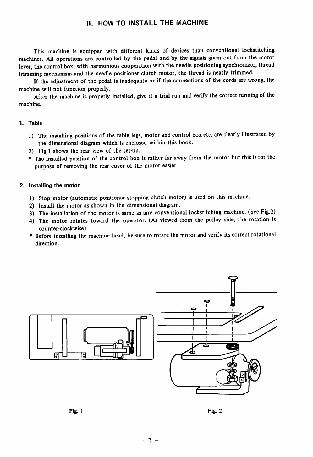
1) Stop motor (automatic positioner stoppingclutch motor) is
2) Install the
3)
The
4)
The
counter-clockwise)
*
Before
direction.
motor
installation
of the
motor rotates
installing
the
as shown in the dimensional diagram.
motorissame
toward
machine
the operator.
head,besure
asany
conventional
(As
viewed
to rotate the motorand
from
a
used
on this
lockstitching
the
pulley
verify
I I
I !
machine.
machine.
side,
(See
Fig.2)
the rotation is
itscorrect rotational
Fig. 1
- 2 -
Fig. 2
Page 5
50
cycle
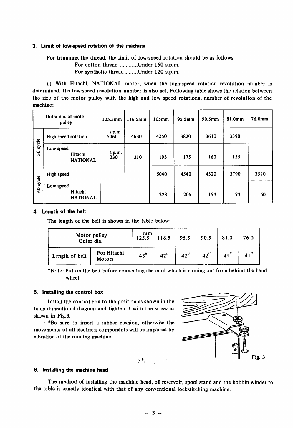
3.
Limitoflow-speed
For
trimming
1)
With
determined,
the
sizeofthe
machine:
Outer
the
dia.ofmotor
pulley
High speed
Low
speed
the
For
cotton
For
synthetic
Hitachi,
low-speed
motor
rotation
Hitachi
NATIONAL
rotationofthe
thread,
the
limitoflow-speed
thread
thread
NATIONAL
revolution
pulley
with
the
125.5mm
s.p.m.
5060
s.p.m.
230
machine
motor,
number
high
116.5mm
4630
210
Under
Under
when
is also
and
150
120
low
105mm
4250
rotation
s.p.m.
s.p.m.
the
set.
speed
193
shouldbeas
high-speed
Following
rotational
95.5mm
3820
175
follows:
rotation
table
shows
revolution
the
relation
numberofrevolutionofthe
90.5mm
3610
160
81.0mm
3390
155
number
between
76.0mm
is
High speed
_9}
"o
>,
u
'
Low
o .
vo
4.
speed
Lengthofthe
The
lengthofthe
Lengthofbelt
*Note:
Putonthe
wheel.
5. Installing
table
dimentional
shown
'
Install
in Fig. 3.
*Be
sure
the
the
movementsofall
vibrationofthe
Hitachi
NATIONAL
belt
beltisshowninthe
Motor
Outer
belt
control
control
boxtothe
diagram
to
insertarubber
electrical
running
machine.
pulley
dia.
For
Hitachi
Motors
before
box
and
components
table
mm
125.5
43"
connecting
the
positionasshowninthe
tightenitwith
cushion,
will be
the
otherwise
impaired
5040
228
below:
116.5
42"
cord
whichiscoming
screw
as
the
by
4540
95.5
42"
206
4320
193 173
90.5
42"
out
from
81.0
41"
3790
behind
76.0
41"
the
3520
160
hand
.
"1-
6.
Installing
The
the
table is exactly identical with
the
method
machine
of installing
head
the
machine head, oil reservoir, spool stand and
that
of any conventional lockstitching machine.
- 3 -
the
bobbin winder to
Fig. 3
Page 6
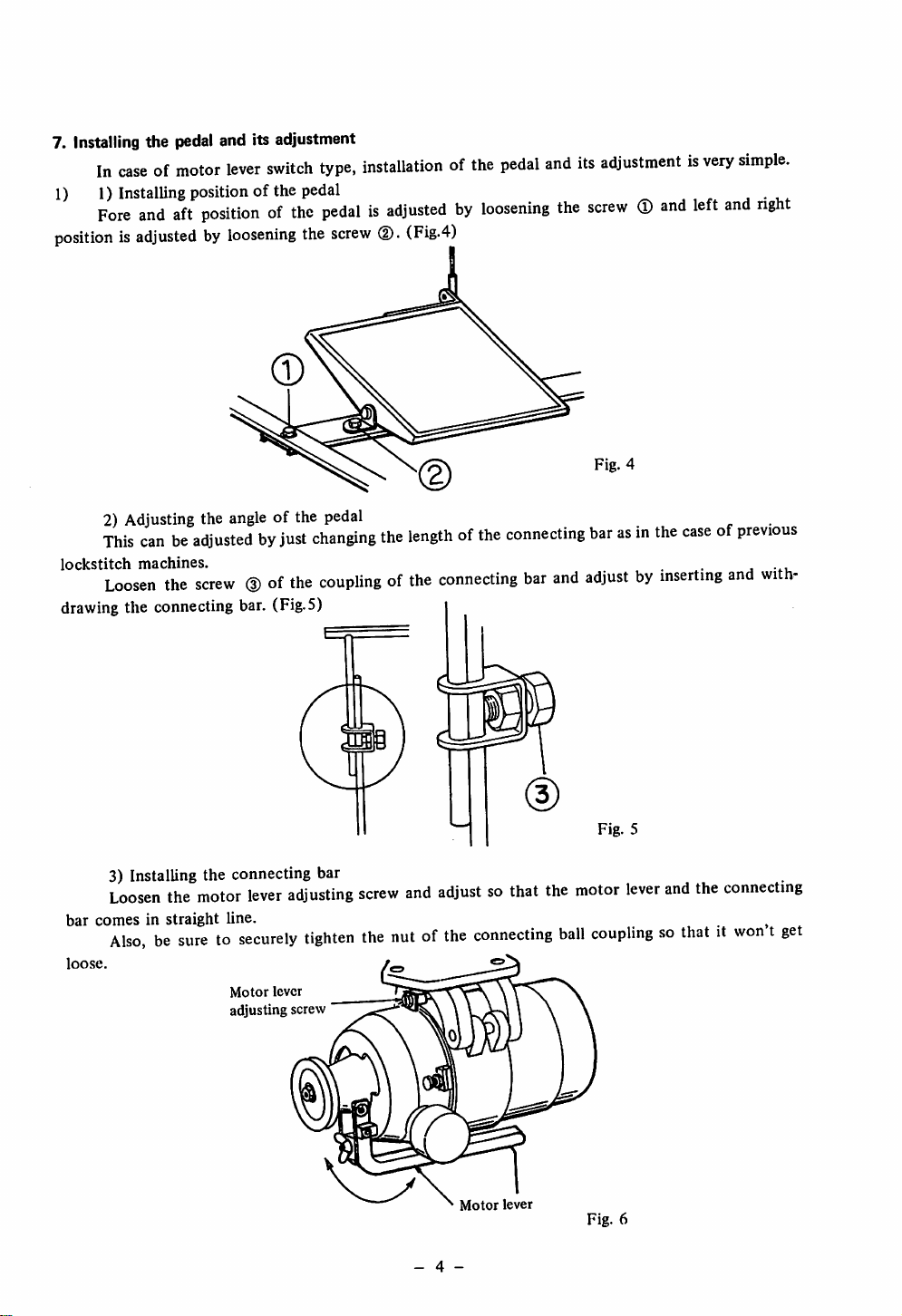
7. Installing the pedal and its adjustment
In
caseofmotor
1) 1)
positionisadjustedbyloosening
Installing
Fore
and
lever
position
aft
positionofthe
switch
ofthe
type,
pedal
pedalisadjustedbyloosening
the
screw
installationofthe
(Fig.4)
pedal
and
the
its
adjustmentisvery
screw
(T)
and
Fig. 4
left
simple.
a •
and
right
U4-
2) Adjusting the
This
canbeadjustedbyjust
lockstitch machines. j
Loosen
drawing
3) Installing the connecting bar
Loosen
bar comes in straight line. ^
the
the connecting bar. (Fig.5)
the
Also,besuretosecurely
loose.
angle
screw(Dof
motor
lever
Motor
lever
adjusting screw
of the pedal
changing
the
couplingofthe
adjusting
tighten
the
screw
the
nutofthe
lengthofthe
connecting
and
adjustsothat
connecting
connecting
bar
barasin
and
adjustbyinserting
the
motor
ball
couplingsothatitwontget
Fig.
5
lever
the
caseofprevious
and
and
the
connecting
with
Motor
lever
- 4 -
Fig.
6
Page 7
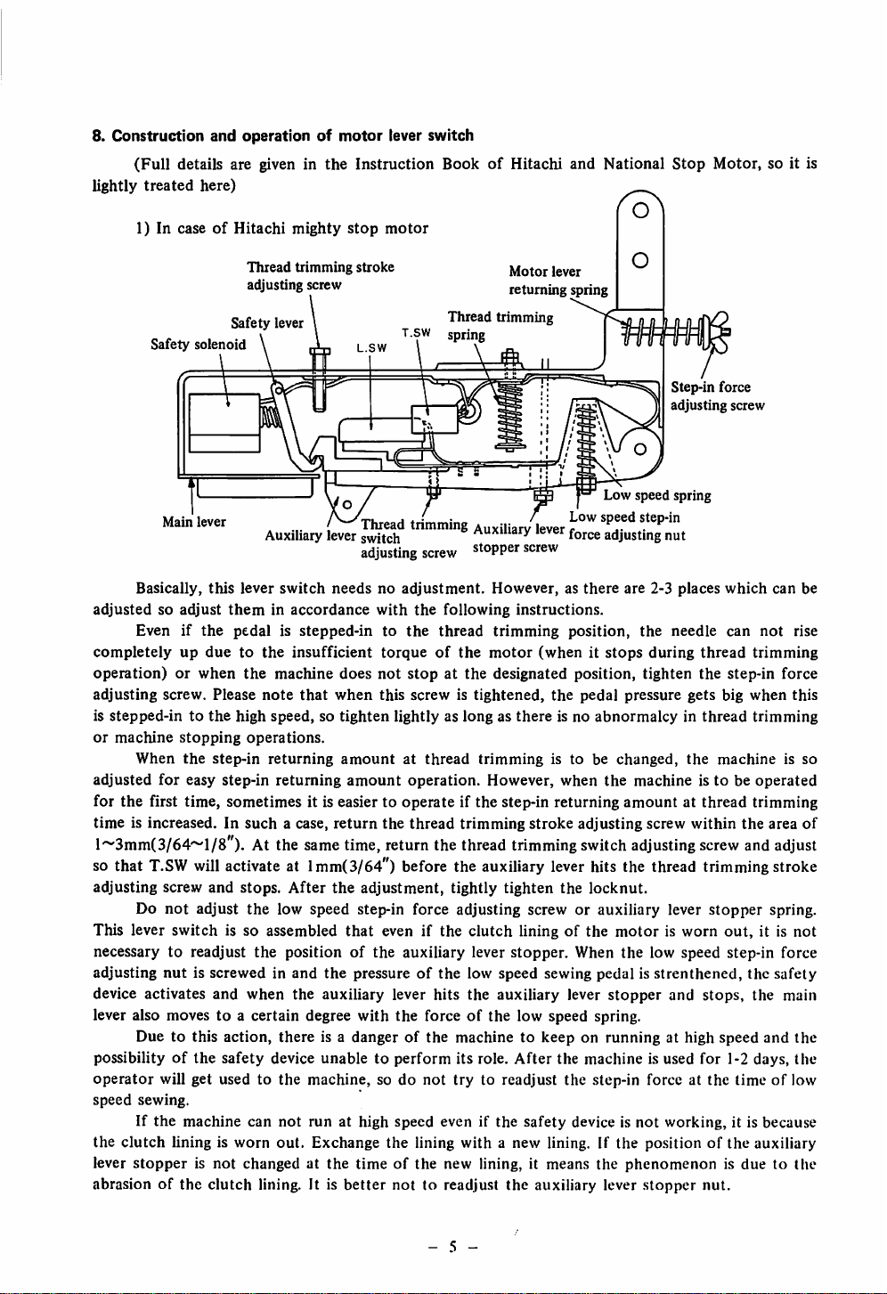
8.
Construction
(Full
lightly
treated
and
operationofmotor
details are given in
here)
the
Instruction
lever switch
BookofHitachi and National
Stop
Motor, so it is
1)IncaseofHitachi
Safety
Safety solenoid
Main
lever
Basically,
adjustedsoadjust
Even if
completelyupduetothe
operation)orwhen
adjusting
is
stepped-intothe
or
machine
When
adjusted
for
the
first time, sometimes it is easier to operate if the step-in returning
time
is increased. In
this
theminaccordance
the
screw. Please
stopping
the
step-in
for
easy
step-in
pedalisstepped-intothe
high speed, so
l~3mm(3/64~l/8"). At the sametime, return the thread
so that
adjusting screw and stops.
This lever
necessarytoreadjust
adjusting
device activates and when the auxiliary lever hits the auxiliary lever
T.SW
Do
will
activate at lmm(3/64") before the auxiliary leverhits the thread trimmingstroke
not
adjust
switch
is so assembled
nut
is screwed in and
mighty
Thread
adjusting screw
lever
Auxiliary
lever
switch
insufficient
the
machine
note
operations.
returning
returning
such
a case,
After
the
low speed step-in force adjusting screw or auxiliary lever
the
positionofthe
stop
motor
trimming
/^
lever
stroke
L.SW
Thread
switch
adjusting
needsnoadjustment.
with
torqueofthe
does
not
that
when
this screw is
tighten
amount
amount
return
the
the
adjustment,
that
even if
the
pressureofthe
Motor
returning
Thread
T.sw spring
trimming
screw
the
following
thread
stop
at the designated position,
lightly as
at
thread
operation.
thread
trimming
Auxiliarv'lever
Auxiliary
stopper
However,asthere
instructions.
trimming
motor
tightened,
longasthere
trimming
However,
trimming
trimming
tightly
the
auxiliary lever
tighten
clutch
liningofthe
stopper.
low speed sewing pedal is
lever
spring
lever
force
screw
position,
(whenitstops
the
pedal
is no
abnormalcyinthread
is to be
when
stroke
adjusting
switchadjusting
the
locknut.
When
adjusting
the
stopper
changed,
motorisworn
the
lever also moves to a certain degree with the force of the low speed spring.
Due to this
possibilityofthe
operator
speed
the
lever
will get used to the machine, so do
sewing.
If
the
clutch
stopperisnot
abrasionofthe
action,
safety
machine can
lining is worn
changed at
clutch
there
is a dangerofthe machine to
device
unabletoperform
not
run at high speed even if the
out.
Exchange the lining with a new lining. If the position of
the
timeofthe
lining. It is
better
not to readjust the auxiliary lever
its role.
not
try
to readjust the step-in force at
new lining, it means the
keeponrunning
After
the machine is used for 1-2 days,
safety
device is
Step-in force
adjusting screw
speed
spring
nut
are
2-3
places
which
can
the
needle
during
tighten
pressure
machineistobeoperated
amount
screw
low speed step-in force
strenthened,
and stops, the main
at high
not
working, it is because
phenomenonisdue
stopper
can
not
thread
trimming
the
step-in force
gets
big
when
trimming
the
machine
at thread trimming
within
the
area
screw
andadjust
stopper
the
spring.
out,
it is
the
speed
and
timeoflow
the
auxiliary
safety
to the
nut.
be
rise
this
is so
of
not
the
the
- 5
Page 8
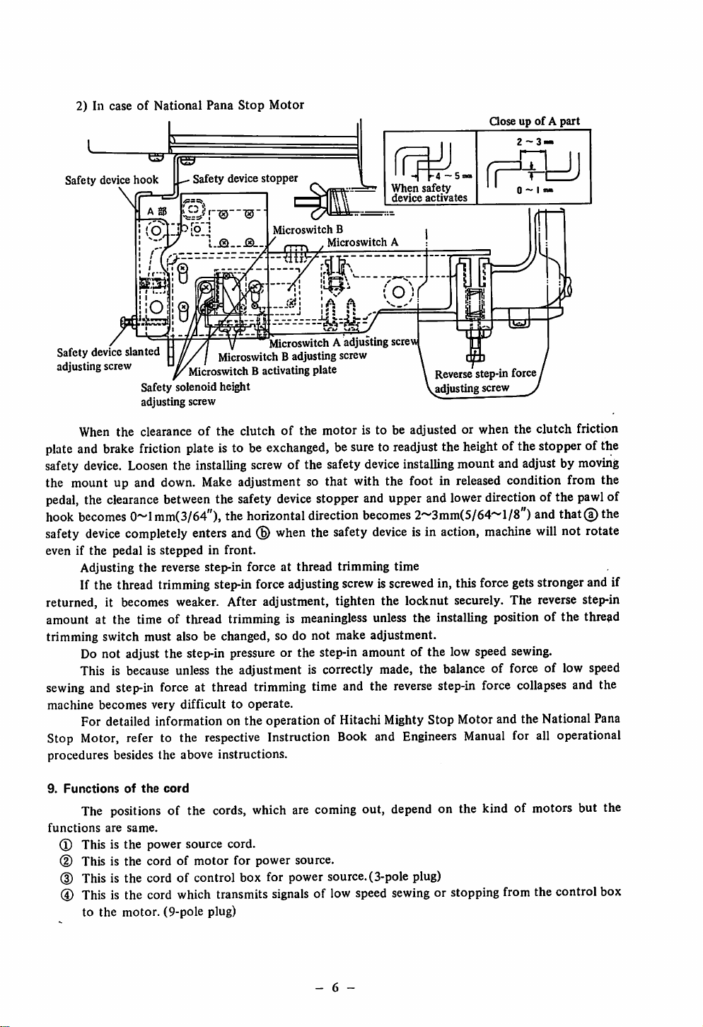
2) In caseofNational
Pana
Stop
Motor
QoseupofApart
2-3.
Safety device
hook
\
Safety device slanted
adjusting
screw
Safety solenoid height
adjusting screw
Safety
device
stopper
Microswitch
Microswitch B adjusting screw
Microswitch B activating plate
Microswitch A adjusting screw
B
Microswitch
When
device
A
>-4 — 5 not
ifety
Si
ictivates
s
Reversestep-in force
adjusting screw
0 - 1 «
m
When the clearanceofthe clutch of the motor is to be adjusted or when the clutch friction
plateand brakefriction plateis to be
safety
device.
the mount up and
pedal,
the
hook
becomes
safety
device
even if the pedal is
Adjusting
Loosen
clearance
the installing
down.
Make
between
0~lmm(3/64"), the
completely enters and
stepped
the
reverse step-in force at thread trimming time
the safety
in front.
exchanged,
screw
of the safety
besureto readjust the
device
installing mount and adjustby
adjustment so that with the foot in
device
stopper and upper and
horizontal
(B)
when
direction
the safety
becomes
device
2~3mm(5/64~l/8")
is in action,
height
released
lower
direction of the
machine
of the stopper of the
moving
condition from the
pawl
and
that@ the
will
not rotate
If the thread trimming step-inforce adjustingscrew isscrewedin, this force gets stronger and if
returned, it
becomes
weaker.
After adjustment, tighten the locknut securely. The
reverse
step-in
amount at the time of thread trimming is meaningless unless the installing position of the thread
trimming switch must also be changed, so do
not
make adjustment.
Do not adjust the step-in pressure or the step-in amount of the low speed sewing.
This is because unless the adjustment is correctly made, the balance of force of low speed
sewing
machine
and
step-in
becomes
force
at thread trimming time and the
very
difficulttooperate.
reverse
step-in force
collapses
and the
For detailed information on the operation of Hitachi MightyStop Motor and the National Pana
Stop
Motor,
procedures besides the above instructions.
refer to the
respective
Instruction
Book
and
Engineers
Manual
for all operational
of
9.
Functions
The positions of the
functions
(l)
Thisisthe
(D This is the
are
of
same.
the
cord
power
source
cordofmotor
cords,
cord.
for
which are
power
source.
coming
out, depend on the kind of motors but the
(D This is the cord of control box for power source.(3-pole plug)
@ This is the cord which transmits
to the motor. (9-pole plug)
signals
of low speed
- 6 -
sewing
or stopping from the control box
Page 9
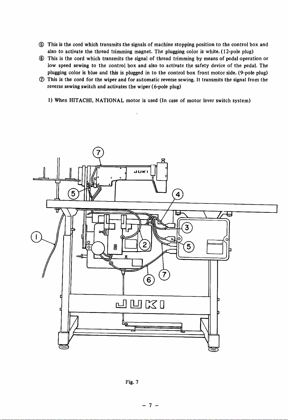
® This is the cord which transmits the signals of machine stopping position to the control box and
alsotoactivate
the
thread
trimming
magnet.
The
plugging
coloriswhite.
(12-pole
plug)
(D This is the cord which transmits the signal of thread trimming by means of pedal operation or
low
speed
sewingtothe
plugging
(2)
This is the cord for the wiper and for automatic reverse
reverse sewing
color
is blue
switch
and
and
control
this
is plugged in to
activates
box
the
and
alsotoactivate
wiper
(6-pole
the
control
sewing.
plug)
the
safety
deviceofthe
box
front
motor
side. (9-pole plug)
It transmits the signalfrom the
pedal.
The
1) When HITACHI, NATIONAL
JJ
motor
UUK
is used
I
(In
caseofmotor
lever switch system)
i-i][U]c:^a
Fig. 7
- 7
Page 10
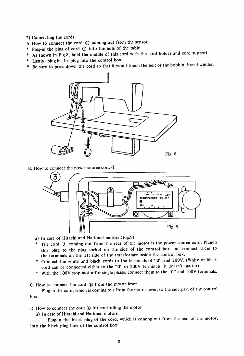
2) Connecting the cords
A. How to connect the cord (D coming
Plug-in
As
Lastly,
Be
the
plug
of cord
showninFig.8,
plug-in
suretopress
the plug into the control box.
down
(§)
into the
hold
the
middleofthis
the
cordsothatitwon't
out
from the sensor
hole
of the
cord
table.
with
touch
the
cord
the
beltorthe
holder
and
cord
bobbin
support.
thread
winder.
B. How to connect the power source cord
a) In case of Hitachi and National motors (Fig.9)
*
The
cord3coming
this
plugtothe
the terminals on the left side of the transformer inside the control box.
*
Connect
cord can be connected either to the
*
With
C. How to
Plug-in
box.
D. How to connect
a) In case of Hitachi and
into
the
the
white
the
lOOV
connect
Plug-in
black plug hole of the control box.
the
the
cord,
the
the
out
from
plug
socketonthe
and
black
stop
motor
for
cord (6) from the
whichiscoming
cord ® for controlling the
National
black
plug
of the
the
cords
single
out
motors
cord,
(3)
rear
of the
motor
sideofthe
to the
terminals
"0"
or 200V terminals. It
phase,
connect
motor
lever
from
the
motor
motor
whichiscoming
\ 1 1 '
transformer
a
2Ry
/ / 1 \ \
control
of "0"
them
lever,tothe
M
isthe
out
AWi
for
att
•!
Fig.
power
box
and
cloesn
to the"0"
from
9
source
and
200V.
and
side
the
connect
t matter)
partofthe
rear
cord.
Plug-in
them
to
(Whiteorblack
lOOV
terminals.
control
of the
motor,
- 8
Page 11
10.
Howtohandle
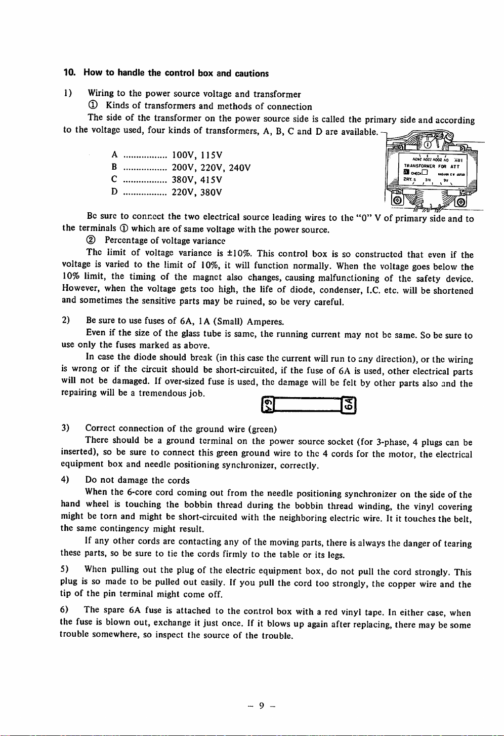
1) Wiring to the power source voltage and transformer
® Kinds of transformers and methods of connection
The
side
to the voltage used, four kinds of transformers, A, B, C and D are available.
of the
the
control
transformer
box
on the
and
cautions
power
source
sideiscalled
the
primary
side
and
according
A lOOV, 115V
B
C
D
Be
sure to connect the two electrical source
the terminals® whichareof same
(D Percentage of voltage variance
The limit of voltage variance is ±10%. This control box is so constructed that even if the
voltageisvaried
10%
limit,
However,
and sometimes the sensitive parts may be ruined, so be very careful.
2) Besure to use fuses of 6A, 1A (Small) Amperes.
use
is
wrong
will
repairing will be a tremendous job. -
3) Correct connection of the ground wire (green)
Even
only
In
not be
when
the
case
or if the
There
inserted),
equipment box and needle positioningsynchronizer, correctly.
4) Do
hand
so be
not
When
wheelistouching
mightbetorn
the
same
contingency
If
any
these
parts, so be sure to tie the
5)
When
plug
is so
tipofthe
6)
the
trouble
pin
The
spare6Afuseisattached
fuseisblown
somewhere,
to the limit of
the
timing
the
if the sizeof the
fuses
markedasabove.
the
diode
damaged.Ifover-sized
should
suretoconnect
damage
the 6-core cord coming out from the
and
mightbeshort-circuited
other
cords
pulling
made
to be
terminal
out,
200V,
220V,
380V,
415V
220V,
380V
voltage
10%,itwill
of the
voltage
should
circuit
magnet
gets too
glass
tube is
break
shouldbeshort-circuited,
fuseisused,
be a
ground
terminal
this
the
cords
the
bobbin
might result.
are
contacting
cords
out
the
plug
of the
pulled
out
easily.
might
come
off.
exchange
so inspect
it just
the
sourceofthe
240V
leading
with the power
function
also
changes,
high,
the life of diode, condenser,
same,
the runningcurrent may not be
(in
this
case
the
normally.
causing
current
if the
the
damage
dL
on the
green
thread
anyofthe
firmly
electric
If you
to the
once.
power
sourcesocket(for
ground
with
during
the
wire
to the 4
needle
positioningsynchronizer on the sideof the
the
bobbin
neighboring
moving
to the table or its
equipment
pull
the
cord
control
box
If it
blowsupagain
trouble.
withared
wires
to the
"0"
source.
When
the
malfunctioning
will
runtoany
fuseof6Aisused,
willbefelt
by other
dl
cords
for the motor,the
thread
winding,
electric
parts,
thereisalways
legs.
box,
do not
too
after
pull
strongly,
vinyl
replacing,
wire.
tape.Ineither
Vof
voltage
I.C.
direction),
3-phase,4plugs
the
the
AOK AOJJ
TRANSFOHUER FOR ATT
9
OCCkCI
2RY. S Siv 9v
primary
goes
of the
etc.
will
same.
other
electrical
parts
the
It it
touches
the
dangeroftearing
cord
copper
there
AOOJ
AO AMI
usuuc»iini
sideand to
below
safety
device.
be shortened
Sobesureto
orthe
wiring
parts
also
and the
can be
electrical
vinyl
covering
the
belt,
strongly.
wire
case,
This
and the
when
maybesome
the
9 -
Page 12
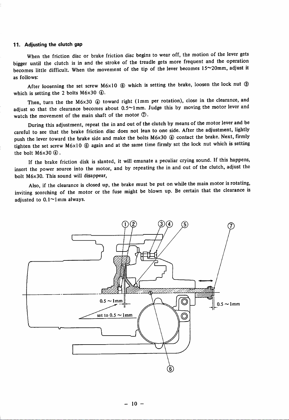
11. Adjusting
When
bigger
until
becomes
as
follows:
After
which is setting the 2 bolts M6x30 ®.
Then,
adjustsothat
watch the movement of the main shaft of the motor
During
carefultosee
push
the
tighten
the
bolt
If the
insert
the
bolt
M6x30.
Also,ifthe
inviting
adjustedto0.1~lmm
the
clutch gap
the
friction
the
clutchisin
little
difficult.
loosening
turn
lever
the
set
M6x30
power
this
brake
This
the
the
the
the
clearance
adjustment,
that
the
toward
screw
M6xl0®again
® .
friction
source
sound
clearanceisclosed
scorchingofthe
discorbrake
and
the
When
the
movement
set
screw
M6xl0®whichissetting
M6x30®toward
becomes
repeat
theinand
brake
friction
the
brake
side
and
diskisslanted,itwill
into
the
motor,
will
disappear,
up,
motororthe
always.
friction
disc
strokeofthe
of the tip of the
right
about
0.5~lmm.
outofthe
disc
does
not
make
the
andatthe
same
andbyrepeating
the
brake
fuse
mightbeblown
beginstowear
treadle
(1mm
per
Judge
(2).
off, the
gets
more
lever
becomes
the
brake,
rotation),
thisbymoving
clutchbymeansofthe
leantoone
bolts
M6x30®contact
time
emanateapeculiar
side.
firmly
set
crying
theinand
mustbeputonwhile
up.Becertain
motion
frequent
15~20mm,
loosen
closeinthe
the
After
the
the
the
lock
sound.
outofthe
the
main
that
of the
lever
and
the
operation
adjust
the
lock
nut
clearance,
motor
lever
motor
lever
adjustment,
brake.
Next,
nut
whichissetting
If this
happens,
clutch,
adjust
motorisrotating,
the
clearance
gets
(D
and
and
and
be
lightly
firmly
the
it
is
0.5~1mm
setto0.5~1mm
-
10
-
0.5^1mm
Page 13

III.
HOW
TO
OPERATE
1.
Cautionsonoperation
Turn
the switch on
direction
of
the
machine.
once
THE
and
MACHINE
after
turning it off,
steponthe
pedal and observe the
rotational
* Unpack the machine and after setting it up, clean it well.
* Before operating this machine, please read and digest every paragraph of the INSTRUCTION
BOOK
on DDL-552, 553 and 555 or DLN-4I5, DLU-450, DLD-432 thoroughly.
* Do not run the machine without filling up the oil reservoir.
* The machine should rotate toward the operator. (As
counter-clockwise).
Do
not
run
the
machineinthe
* For the first month, drop the speed to 4,500 s.p.m. for
s.p.m. for
DLN-415-3
and 3,800 s.p.m. for
DDL-553-3,
viewed
reverse
from the pulley side, the direction is
direction.
DDL-552-3
DLU-450-3
and
and
DLD-432-3.
DDL-555-3
and 4,300
After that,
increase the speed depending on the nature of work and the capability of the operator.
*
When
the power switch is turned on, do not put your hands around and under the needle parts.
* When the
power
switch is
turned
on, do
not
touch
the
hand wheel.
* When the machine head has to be tilted for oiling or cleaning, be sure to turn the switch off.
* If the needle does not stop at the top position evenwhenthe pedalisstepped on toward the rear,
turn
the
switch
off.
* When transporting the machine, do not touch the cover on the rear part of the hand wheel.
* Sometimes when the power switch is turned on and the thread is trimmed but if you step on the
pedal to the rear immediately after these actions, the needle will not come down and trimming
cannotbedone.
down
and
normal
In such a case,
trimming
canberesumed.
just
steponthe
pedal
toward
front
once
and
the
needle will
come
2. Lubrication and adjusting
the
oiling
amount
Before running the machine, fill up the oil reservoir with the designated JUKI industrial
machine oil to the "HIGH" mark.
separate
3.
Trial
instruction
runofthe
volume.
machine
Please
refer to the chapter on "Lubrication and drainage" on the
* At first, verify the correct movement of the machine without passing the thread.
1) When the power switch is turned on, the needle always stops at the raised position. In case
the needle does not stop at the raised position, refer to the chapter on "Malfunctions and corrective
mea.sures"
and
make
proper
adjustment.
2) Step on the pedal lightly toward front and verify the correct low speed sewing operation.
If the
machine
functions
to ascertain
and
3) After the pedal is stepped on front (away from the operator) and
that
does not function
corrective
the
machine
measures".
stops
with
even
after thesere-adjustments, referto the chapteron "Mal
the
foot is released, be sure
the
needle at
lower
position.
-
II
-
Page 14

4) Step on the pedal
5)
Re-adjusting
Step
on the
of the
magnet
If these
the
pedal
will
if the
machine
machineatthis
6) Insert
Note:
*"Front"
*"Rear"
the
pedal
working
movements
not
move
should
the
move
position.
needle
means
means
toward
low-speed
toward
from
rear
under
rear and
switch
(the
thread
the
bed,
verify
and
immediately
are repeatedoverand over
toward
and
front
for
low-speed
start
away
toward
any
sewing.
from
the
operator
more.Atthis
sewing,
the
operator
the tlircad
verifying
trimming
again,
re-adjust
trimming
the
correct
switch
will
step
on the
invariably there
position,
the
the
low-speed
operation.
working
start)
andifyou
pedal
machine
sewing
of the
safety
hear
tov/ard
will
bea position
front.
willbestopping
switch
device.
the
sound
where
but
to stop the
4. Howtooperate
As
showninFig.
CD
The
(D
When
(D
When
@
When
*
Normal
either from high speed or low speed sewing.
thread
* After the
to the
neutral
needle
goesupand
the
pedal
10, the
pedal
machineisstopping
the
pedalissteppedonlightly
the
pedalissteppedonfurther
the
pedalissteppedonfully
trimming
machine
can be
hasstarted the
position.Itis
stops.
of this
byjust
performed
trimming,
not
necessarytokeeponsteppingonthe
machine
resting
functions in 4
your foot
to front, it
lightly
becomes
stronglytofront,itbecomes
toward
High speed
Low
Stopped position
"
Thread
rear,
the
machine
even
if the pedalisstepped on abruptly to the rear
the
trimming
speed
trimming
canbedone
stagesasfollows:
on the
pedal.
low-speed
sewing.
high
will
perform
even
if the
pedal
speed
thread
pedal
to the
sewing.
trimming.
isreturned
rear
until
HIGH
LOW
STOPPED
POSITION
the
SPEED
SPEED
THREAD
TRIMMING
Fig.
10
-
12
-
Page 15

* When the machine is stopped, the needle always comes down and stops.
* If the lowered needle is to be raised up again, step on the pedal toward rear fully. Needle goes up
and
stops
after
the
trimming
(Caution)
After completing the trimming (stepping the pedal to rear), if you try to step on the pedal to
front suddenly, sometimes the pedal
is acting to prevent any undue damage to the machine. In such a case, return the pedal to the rear
once
and
then
step
on
running.
5.
Threading
*The needle always stops at the raised position. But if it is at the lowered position when thread
ing the machine, step on the pedal toward rear once and do the trimming action once. Then the
needle will goupand
*Pass the needle thread in the order of (D ~
the
machine
stops
the
pedal
there.
action.
toward
will
not
move.
front
Thisis becausethe safety deviceinsidethe pedal
once
more
and
the
©as
shown in Fig,27.
machine
will
start
its
normal
6. Adjusting
machine. Please follow the procedures as outlined in the INSTRUCTION BOOK on DDL-552, 553
and 555, DLN-4I5, DLU-450 or DLD-432. However, please note
attachedtothis
the
thread
tension (Fig.28)
Adjusting the thread tension of this machine is exactly like a conventional lockstitching
that
due to the thread trimmer
machine,
the
adjustmentislittle
different
than
other
lockstitch
machines.
First
tension
disc
WeakIStrong
(Adjusts
the
thread remaining at
the
trimming >
length
needle
eye
after
(D
(4)
Strong
w
Second
tension
Weak
(adjusts
tention)
the
disc
thread
of
i
Fig. 11
-
13
-
Fig. 12
Page 16

1)
Thread
When
take-up
causing
thread.
the
becomes
spring
skip-stitching
Be
2) Adjusting the first thread tension disc
*When
needle
*For fine threads (synthetic
3) Adjusting the second thread tension
*
Normally,
*
the thread might break at the start of sewing.
4) Adjusting the
The
ing
machine.
causing
the
breakageorslipping
*Asa rule, this
idle
spinning
7.
Adjusting
After
the
standard
control
red mark on the arm and the white mark on the hand wheel are matched with each other.
box)toright
If the
standard
will stop below the standard stopping position (in case of B).
* If the thread should slip out even if the length of needle thread isadjustedafter the thread
is trimmed, rotate the adjusting knob toward the
* If the needle should hit the wiper, rotate the knob toward the "FAST" direction, (toward
[A]
direction).
(Caution)
If the
sometimes the machine does not stop. In such a case rotate the knob toward the "FAST" direction.
take-up.^ring
fine cotton thread or synthetic
may
become
extremely
the tension of the firstthread tension is madestronger,the threadremaining at the tip of
eye
longer.
However,
adjustment
careful.
becomes
the adjustment of this
please
However,
needle
threadto"float"upat
of the
the
needle
the thread is
needle
adjusting
stopping
position
adjusting
too
strongorthe
just
before
the
shorter
note
bobbin
of the
if the
outof
machineisused
bobbin.
stop
stop
and
after
fiber),
that
when
thread
bobbin
tension
the
needle
(Part
number
position
trimmed,
position,
rotate the
leftso that,after the
knobisrotated
(in
caseofA)
knob is rotated too
threads
rangeofmovementofthe
machine
stops
trimming
weaken
discissame
synthetic
tension.
thread
tensionispractically
istoo
weak,
the
thread
at thestartof
with a bobbin
is D
after
thread
this
machine
needle
toward
and
much
the
ifit's
(tetoron,
and
and
when
the tension and for thick thread,
threadisused,
the
bobbin
startofsewing,
1837555
trimming
can
position
threadistrimmed
"FAST"
rotated
"SLOW"
toward
nylon
eic.)arc
sometimes
it is
as any other lockstitching
the
made
ifthe
sameasany
might
spin
and
sewing
caseinwhichamagnet
BAO
and
might
sold
used,
spring
may
machine
weaker,
tensionisadjusted
conventional
idly
at the
for
synthetic
occur.Bevery
separately)
(Fig.13)
change
the
needle
stop
position.
adjusting
direction,
toward
direction, (toward [B] direction).
the
"SLOW"
knob
(I)
and
the
needle
the
needle
the
"SLOW
direction (towardBdirection),
the
tension
become
does
not
the
remaining
make
it stronger.
machines.
trimming
threads,
is built-in to
To adjust to
(on the
has
stopped,
will
stop
direction,
too
trim
too
lockstitch
careful.
side
above
the
of the
wide,
thread
weak,
instant,
thread
prevent
of the
needle
the
the
the
IB)
[A]
^^"FAST"
"SLOW"
Adjusting
)iiiii)ii)i
knob
Standard
stop
position
i/mmn
Throat
needle
plate
Adjusting
knob
Fig.
13
-
14
-
Page 17

8. When low speed cewing is
not
necessary (Fig.14)
* Be sure to cut off the power and makeadjustment.
at
the
startofsewing;
(T)
Cut off the power source.
(D
open
the cover of the control box.
(3)
Pull
function.
Thus,
out the
the low
inserted
speed
® of the
sewing
figure
function can be eliminated without affecting the thread trimming
n
Fig.
from
the pin
14
When
fg)
and
low speed
insert
sewing
is not necessary
it into the pin (0.
9. Carefully
note
the following points
* Be certain that the needle thread comes out smoothly from the thread spindle.
(Otherwi.se,
the remaining thread at the needle eye after trimming will become short and thread slipping out
might
result.)
* When skip-stitching occurs, the bobbin thread may break but the needle thread docs not
break. In such a case, re-adjust the timing of the needle with the sewing hook.
10.
How
to selectthe
1) Presser foot Select small a and b parts (Fig.15)
2) Throat plate Select small needle eye and A part.
3) Needle Finer needle for less thread slippage
4) Sewing hook Automatic lubricating hook with a groove
presser
foot, throat plate,
sewing
hookandfeed dog
5) Feed dog If a feed dog which is commonly used is adopted, there is no problem,
but if an extremely thick feed dog is used, the backside of the dog teeth might be scratched when
the moving
knife
1)
2)
Presser
Throat
moves fully.
foot
plate
}
Na
Fig.
15
-
15
-
Page 18

IV.
ADJUSTING
THE
MACHINE
This machine consists of lockstitching part and the thread trimming part. The lockstitching
function is same as all
other
previous models, so this text will cover the thread trimming part only.
1. Adjusting
the
timingofthe
indicated
before
cam
roller
that
condition,
hand
the
1)
Howtojudge
In
order
lineonthe
Tilt
the
the
upper
(Fig.
wheel
will
matchedsothat
(Fig. 18 (D)
are
indicating line
synthetic
thread.
timingofthe
the
to change
thread
hand
machine,
dead
point
17) will
rotate
the
cometoa
the
indicated
matched
(Fig.l8
(D)
thread
trimming
correct
the
trimming
wheel,
turn
enter
hand
timingofthe
lengthofthe
cam.
accordingtothe
the
hand
andifthe
the
point
sewing
cam
grooveofthe
wheelinthe
where
wheel
lineofthe
togetherasshown
is matched with
cam
trimming
thread
This can be
with
hook
reverse
it will
not
arm
(Fig.18 (D)
in Fig. 18, it
the
indicating line
Thread
cam
cam
remaining at
done
the
easily by
kindofthread
your
hand
until
presser (Fig. 16 (D) is
cam
(Fig.
17)
direction
rotate
than
any
more.Atthis
and
the
becomesacotton
(Fig.l8
trimming
needle eye
used-cotton
the
and
the
after
matching
thread
pushed
will be
interlocked
conventional
trimming,
the
arm
or
synthetic
take-up
deeplytoright,
way,
pointifcam
indicated
lineofthe
thread
hand
timing. But if
(D), it becomes a timing for
Rotational
direction
Mil
with
comes
there.
and
timing is
adjust
the
thread.
just
the
In
the
wheel
the
2)
Howtomatch
First,
No.2,
and
cotton
thread,
the
green
Then,bypushing
roller,
and
normal
not
finally
hook
rotate
tighten
loosen
match
color
without
any
Fig. 16
match
(D),
shaft
more,
the
DLD-4322
the
timingofthe
the2set
the
screwsofthe
indicating
red color (i) with
(Fig.
18)
the
sewing
rotating
the
rotational
push
the
cam
set
screws
lineofthe
hook
hook
direction
cam
(Fig.
Cam
roller
Cam
roller
set
screw
trimming
cam
with
the
shaft
cam
(Fig.17) in
indicating
arm
thread
trimming
arm
the
red color (D and for
presser (Fig.16 (D)toright,
shaft,
rotate
the
cam
only
with
your
finger tips. At
against
17)inthe
the
thread
orderofNo.2
-
16
trimming
-
synthetic
toward
the
cam
and
Rotate
direction
Fig.
17
order
from
lineofthe
thread, red
interlock
the
reverse
position
thrust
No.l.
caminthis
with
hand
set
screw
hand
the
cam
direction
where
collar
wheel.
color
and
the
(Fig.
No.l
(I)
the
than
cam
17)
Set
Thrust
screw
and
(For
with
cam
the
does
and
collar
No.2
Page 19

2.
Adjusting
shown
centerofthe
needleorbobbin
knife
knife
1)
The
in Fig.l9,
might
correctly.
the
correct
hit
Green
positionofthe
positionofthe
when
the tip of the
needle.
When
threadatthe
each
other.
moving
the
retreated
trimming
Therefore,
knife
moving
moving
range
instant,
it is
knife
whenithas
moved to
its
maximum
knifehasretreated to 2~2.5mm(l/6"~3/32")
is less
than
this
whileifit's
very
important
position,itcannot
too
much,
to
match
2
~2.5mm
the
feed
the
positionofthe
dog
scoop
and
range is, as
from
the
up
the
the
moving
moving
Needle
Fig. 18
Moving
knife
Fig. 19
2) How to match the position of the moving knife
This is adjusted by changing the right or left position of the moving knife shaft (Fig.20
®)
when the machine stops. By this adjustment, the interlocking of the cam and the cam roller also
changes, so match the positionofthe thread trimming cam toward the shaft direction, also.
a. First, loosen the magnet set screw (Fig.20 (D and pull
b. Move the magnet link (Fig.20 (£)) downwards and adjust the .screwed-in
out
the magnet link pin (Fig.20 (D).
amount
of the knife
moving shaft adjusting nut (Fig.20 (D). If this nut is screwed in deep, the retreating range of
th the knife becomes greater and if it's loosened, the range gets less.
c. Loosen
both
set screws of trimming cam
(7)
and the thrust collar (6).
d. Match the indicating line of the hand wheel with the indicating line of the arm.
(2)
(In case of cotton thread, match (D with
of Fig.18 and for synthetic thread, match (D with
e. Rotate the set screw No.2 (Fig.20®)(indicated point) of the trimming cam so that it comes to
front and when it comes to front, push the sewing hook presser to right.
f. Move
the
cam to right and left
and
interlock
the
cam
and
the
cam roller.
g. With this condition, as you pull the cam to right, move it toward teh arrow direction until the
cam
cannot
h.
Temporarily
i.
Tighten
j. At this
(D
Is the indicating line of the pulley matched?
(2)Isthe
rotate
anymore.
the
point,
tighten
lock
nut.
verify
the
(Fig.20
the
set
screw
(D)
following:
No.2(Dof
the
roller inserted smoothly into the cam groove?
cam.
(DIs the retreated range of the moving knife 2~2.5mm?
k. Tighten the two set screwsofthe cam securely.
1.
Push the thrust collar against the cam and tighten the two set screws,
m. Attach the magnet link pin in its original position.
(3))
-
17
-
Page 20

The simple
step
partofthe
parallel,
(Note)
1) No
the
the
matter
retreating
2) Verify if
methodtojudge
bed and
positioniscorrect.
how slight
rangeofthe
the
moving knife disposes
the
the
the
correct
forked baseofthe
position of
the
moving knife would be to verify if
knife are paralled to
each
other.Ifthey
the
are
right or left position adjustment may be, it has a big bearing on
moving
knife.
the
thread
properly as shown in Fig.21.
s
0
3. HowtoInstall
The
correct
®(2)(3)®(4
the
fixed
knife
correctly
methodofinstalling
wism
the
0
fixed
knifeisshowninFig.22.
Fig.
Fig. 21
The
20
standard
distance
from
the center of the needle to the tip of the fixed knife is 4.2mm(5/32"). The tip of the fixed knife
shouldbe0.6mm
When
the
cutting
the
cutting
be
changed,
installation
above
the
the
angleofthe
partofthe
power
be sure to verify
(Fig.22A).
fixed
becomes
installing
installing
knife
most
powerful.
the
sharpnessofthe
surface.
fixed
and
the
(Fig.23).
knife's
moving
When
tipischanged,
knife
is precisely
the
fixed
knifeistobeadjustedorwhen
blade
andatthe
the
same
cutting
matched,
time,
power
then
adjust
changes. When
and
only
then
it is
the
angle
to
of
18
-
Page 21

Movingknife
Lower
of
throat
part
plate
Needle
a
Shorter Longer
Length of remaining thread
after trimming
Fig.
22
i.5bb
Graded
of
bed
(Note):
part
0.6mm
DLN-415-2
Set
the
feed adjusting dial to
Fixed
Fig.
knife
23
The fixed knife can be installed by moving it to the right of the standard installation position.
In that case, the length of the remaining thread of needle thread and the bobbin thread not
only gets longer by the distance the fixed knife has
moved,
but
because
the timing of the
trimming also is delayed which makes the length of the thread at the tip of the needle eye
much
longer
(Fig.25)
In the case of synthetic thread, move the fixed knife to right to delay the timing of the thread
trimming. However, to make the adjustment complete, it is alsonecessaryto adjust the timing
of
the
thread
trimmer.
(Chapt.
IV-1).
"0".
4.
The
floating
1)
At
rangeofthe
Howtoverify
the
position
the
where
second
floating
the
take-up
thread
range
has
tension
come
disc
just
before
the
upper
dead
foot and when the hook thread presser (Fig. 16 (D) is pushed hard to right, verify
rangeofthe
Bring
center
Moving knife
2)
Adjusting
second
thread
the
tension
floating
disc is
rangeofthe
0.5~lmm.
second
(DTo increase the floating range, loosen nut
©To
decrease the floating range, loosen nut
After
the
adjustmentiscompleted,
to
Fixed
knife
l(M
Sewing
tighten
Wlien
is
Standard
thread
(B)
and tighten nut
(g)
and tighten nut
both
®
and
fixed
movedtoright
knife
Moving knife
Bobbin
thread
presser
tension
(B>
disc
nuts.
(Fig.26)
©.
©.
point,
®
lower
that
(D
® d) ©
the
presser
the floating
Fig.
24
Fig.
-
25
19
-
Fig.
26
Page 22

5. Howtosharpen
The
shape
most
cases,
just
1)
It is
fixed
©
Just
sharpen
X in
Fig.27)
®
The
cutting
change the angleofx when sharpening.
®
When
blade
same time. Correct
♦
To improve the contacting of the
mark of Fig.29.
does
not
cut
Shave
and sharpen well
Sharpen this surface
A
surface
of the
sharpen
very
knife.
cutting
surface
When
well,
off
Blade
B
the
knife blade
blade
tipof the
the
blade
important
the
power
"A"
becomes
that
surface
powerisnotsogood
of the
moving
the
inclination angle of
the D side of Fig.28 does not cut well,shorten the angle and when the C side
make
the
angle
corners
tip
surface
of the
the
(Fig.27)
weak
knife
larger.
fixed
fixed
blade
surfaceofthe
when
even
and the
Fixed
knife
greatly
knifeand the cutting
affects
moving
and
cutting
the B
though
fixed
the
moving
knife
becomes
surface
the
blade
knife
is not
fixed knife.
and fixed knife,
Moving knife
the
cutting
becomes
knife
should
better.
(Note
tipissagging
tips
are
sharpened,itis
contactingtoright
change
power
and
the
sharper.
contact
the
angle
blunted.
angle
ofthe
knife.
the
blade
shown
So,donot
because
andleftat the
of the arrow
Fixed
In
of
by
the
knife
Fig.
27
Changing
the
moving knife
To change the moving knife, do as follows:
1)
Loosen
pin
2)
Remove
and
the moving knife from the knife forked base.
3)
Move
screw
the
(Fig.32
the
the
moving
the
(Fig.3IB).
knife
(D).
moving
knife
forked
knife
knife
forked
For
Fixed
base
hinge
(Fig.30
basetothe
this
purpose,
Fig. 29
knife
pin
(D)tothe
set
screw
position
use
screw
(Fig.32®)and
(Fig.30
®),
position
showninFig.31B
the
special
C&D
partsofmoving
should contact each other at the same time
Fig. 28
pull
out
the
knife
knife
and
forked
fixed
. . •
move
the
knife
forked
showninFig.31Aand
and
remove
spanner
in the
accessories
base
remove
the
knife
box.
(Fig.30
the
knife
base
/-n
(D)
pin
ol
hinged
Fig.
30
-
20
-
Page 23

move
knife
the
the
N (
Knife
forked
base
Moving knife
For
installing
the
moving
forked
forked
base). When
base.
Fig.
back,
reverse
knife
with
base to
the
position
(If
the
knife
the
shaftismovedtoright,besure
the
your
hand
showninFig.31C
moving
Knife hinged
Moving
/
31A
Knife
above
and
shaft
forked
screw
knife
procedure.
see
if it
is moved to right or
base
Fig.
moves
and
to see
31B
After
firmly insert
that
the
smoothly
the
knife
knife
hinged
without
the
knife
left,
the
movestoright,
Knife
Moving knife
screwistightened,
any
rattling.
forked
base
pin will go in
also.
forked
base
Fig.
31C
Match
pin
deep
the
into
into
7. Adjusting
the
bobbin
thread
presser
If the bobbin thread presser (Fig.32 (3)) is penetrating too deep toward the bobbin case at the
trimming time, the bobbin will not rotate and the bobbin thread will be trimmed too short, causing
thread
slippage at
the
startofsewing.
On the contrary, if it is not inserted deep enough, the needle thread will slip out from the tip
of the bobbin thread presser at the trimming time, shortening the thread remaining amount at the
tip of the needle eye after the trimming and invites thread slipping out.
1) The correct position of the bobbin thread presser
When the thread trimming lever is pressed hard against the stopper side, the bobbin thread
should be pulled out easily. At this position, the clearance between the tip (Bobbin presser) of the
bobbin thread presser and the upper carved part of the bobbin should be 1.5~2mm asshown in Fig.47.
1.5
~2mm
a
Fig.
DLD-432'2
32
V
Fig.
33
2) How to adjust the bobbin thread presser
Loosen
ond
down.Atthis
the
position
After
shaft is not contacting the bottom of the
contacting, refer to the chapter on "Adjusting the
shaft
collar.
the
screws
instant,
of the
adjusting,
(Fig.32 ®), and adjust by
adjust
the
fore
thread
trimming
tighten
the set
stopper
screw
and
arm
of the
cam
aft
moving
position
(Fig.26
the bobbinthread
ofthe
(D).Asshowninfigure.
stopper.Besuretoverify
-
groove
21
slide
-
when
the stopper is
shaft" and
bobbin
re-adjust
presser
in and out or up
thread
presser
that the tipofthe
deeply
the positionof the
and
inserted. If it's
adjusting
roller
slide
Page 24

8.
Adjusting
The
the
moving
slide
range
shaft
of the
slide
shaft
(Fig.34
®) is
5.4mm(7/32").
Thisisadjustedbymoving
the slide collar (Fig.34 (D) toward the shaft direction. Also, the position of the cam roller shaft arm
(Fig.34 (D) should be 13.5mm(33/64") as
*
The
adjusting
procedure
is as follows:
showninFig.34.
(D Determine the position of the thread trimming arm stopper depending upon the position of
the
hook
thread
presser.
(D Adjust the position of the slide collar so
that
the moving range of the slide shaft comes to
5.5mm(7/32").
(D Adjust the position of the thread trimmer magnet (DC solenoid).
When
the
thread trimming arm has moved to
the
position were it is almost touching
the
stopper,
adjust the position of the thread trimming magnet so that the snap ring which is attached to the
thread trimming magnet plunger hits the rubber ring and stops and also when the magnet is pulling,
there
shouldbeno
clearance
between
the
two
endsofthe
rubber
ring.
E
20mm
13.5mm
Fig.
34
9.
Howtoinstall
To remove
®Take
(D Loosen the knife forked base (Fig.35 (D), and pull
(D After removing
hinged screw
base
will
come
and
the
remove
knife
the
installing base (Fig.35
out the sewing hook.
the
hook
(Fig.35
®)
knife
off.Toinstall
installing base set screw
back,
knife
installing base
thread presser link hinged screw (Fig.35 (D), and if
reverse
this
®),
do as follows in
order.
out
(Fig.35
Fig.
order:
the
knife forked base pin
(D) is pulled
out,
35
the
the
hook
knife
(Fig.35
presser
installing
(D).
Page 25

10. Adjusting
This synchronizer has adopted semi-leading element, non-contacting type called hole IC, so it
is impossible to verify the position of the synchronizerby the tester by pulling out the 12P
Therefore, the position of the synchronizer should be adjusted in the following order:
®
(D
(DTurn
®
(D
the
position of
Remove
Remove the cover ® of the synchronizer and loosen the screw
Match
If the
the
belt.
the power source switch to
the
black
synchronizerismoved
the
synchronizer (Fig.36)
"ON".
indicating lineof the
gently
pulley
withthe redindicating lineof the
by the
hand
without
moving
®.
the
pulley,
machine
the
auxiliary
plug.
head.
motor will either rotate or stop. So, at the position where the auxiliary motor has started to stop,
tighten
the
(D
Replace
screw
®.
the
cover
of the synchronizer to the
original
position.
(Note)
When
the
above
adjustments
are
made,
do not
loosen
the
screw(©(+
screw),
absolutely.
this part is either loosened or released, sometimes the synchronizerdoes not function. So,
use
extreme
caution.
Fig.
36
0
0
If
-
23
-
Page 26

11. In caseofelectrical malfunctions, be sure
discrepancies: (Refer to malfunctions and corrective
measures for
complete
to
investigate
details)
the
following
No.
1
2
3
4
Malfunctions
Does
not
speed
Main
motor
over-heated
Auxiliary
over-heated
Enters
speed
running
the
power
"ON".
runatlow
motor
into
low
source
Causes
1.
Defective
2. Motor cord is pulled
stop at upper
3. Inadequate plug-in
triode
4. Wireofauxiliary
connected.
5. Inadequate returningofMB
part..
L.SW
thyristor
switch.
stop
printed
out
position).
of
bi-directional-
board.
motor
is dis
(does
not
clutch
6. Low speed function changing pin is
Corrective
* Exchange the L.SW switch.
* Plug-in
correctly.
* Plug-in correctly.
*
Connector
is
disconnected.
* Repair
the
* Replug-in the pin to the
inside
clutch
measures
the
motor
part
with oil stone.
"on"
(end
cover)
side.
connected to the low speed (ofO side.
(Inside
the
control
box).
the
is
1. No
clearanceatclutch
part.
2. One phaseof3 phases is disconnected
(single phase running).
* Adjust
* Inspect the plug-in conditionofthe
power
(Verify
the
is
1. Inadequate returningofthe MB part.
2. Inadequate lead relay (contact point)
of
3. One phase
3 phases is disconnected.
1. Inadequate positionofL.SW switch.
with
2.
Defective
3. 12P
L.SW
switch.
connectorofheadispulled
4. Inadequate adjustment of the adjust
ing
knobofstopping position.
5. Pedal cord is pulled
upper
stopping
position).
out
(make it to
out
* Repair the clutch part with oil stone.
* Exchange
*
Connector
is
disconnected.
* Adjust the positionofL.SWswitch.
* Exchange
* Re-plug-in
*
Rotate
direction.
* Re-plug-in
clearanceofclutch part.
source cord.
the
fuseofthe
plant)
the
lead relay.
inside
the
the
L.SW switch.
the
connector.
the
knob
toward
the
connector.
power
motor
the
source
(end
"FAST"
of
cover)
5
6
Machine
stop
running
does
(keeps
at low
speed)
Does
not
low speed.
trimming
performed
stopsatany
on
rotate
Thread
not
and
1.
not
Defective
2.
Too
3.6Afuseisblown
L.SW
much
clearanceofmagnet
switch.
out.
4. Pressure of returning springofmotor
leveristoo
5. 12P
at
1.lAfuseisblown
weak.
connectorofheadispulled
out.
brake.
out.
* Exchange
* Re-adjust the clearance.
* Exchange the 6A fuse.
* Tighten the adjusting screw.
* Re-plug-in correctly.
* Exchange
the
L.SW switch.
thelAfuse.
position.
-
24
-
Page 27

V. HIGH
SPEED,
UNDERTRIMMER
SINGLE
NEEDLE,
EQUIPPED
LOCKSTITCH,
WITH
A
WIPER
AUTOMATIC
1.
Adjusting
The
adjust
the
positionofthe
it as
follows:
1)
Rotate
positionofthe
wiper is adjusted
the
hand
wheel
point (Dofthe hand wheel so
z
wiper
toward
that
Model
it will
DDL-552-2-3
DDL-553-2-3
DDL-555-2-3
accordingtothe
the
regular
match
with
direction
the
DDL-552-2-4
DDL-553-2-4
DDL-555-2-4
thicknessofthe
andasshown
sewing
in Fig.37,
red point (Dofthe
frame.
cloth.
bring
2inin
Normally,
the
white
1mm
Fig. 37
Fig.
38
2) Then, as shown in Fig.38, insert the wiper ® into the driving shaft (D and bring the tip
of the
wiper
that
the
space
so that it
between
will
come
to 2mm(approx. 1/16") under the point of the
the
flat surfaceofthe
wiper
and
the
centerofthe
needle.
needle comes to
(approx. 5/128").
Make
sure
1mm
-
25
-
Page 28

2.
Adjusting
moving
1)
Pullinthe
the
wiper
the
positionofthe
plunger
magnetupand
comes to the position where it
this
adjustment,
securely
tighten
wiper
magnet
entirely
into
the
coil,
loosen
the
wiper
magnet
down
andasshowninFig.3,
will
be away from the needle center by 2mm (approx. 1/16"). After
the
wiper
magnet
set
screw.
adjustsothat
set
screw
the
edgeofthe
0
and
by
wiper
Fig.
2min
With
the
exceptionofabove, all
operating
-
instructions
26
-
and
adjustments
39
are same as DDL-555-2.
Page 29

VI. HIGH SPEED, SINGLE NEEDLE, LOCKSTITCH INDUSTRIAL
SEWING
AND
MACHINES
AUTOMATIC
WITH
REVERSE
AUTOMATIC
SEWING
THREAD
UNIT
TRIMMER
1.
Howtosew
(DIf the push
in reverse sewing
(D As long as this
do
reverse
(DIf the
sewing
automatically
button
sewing.
button
condition.
Model
(i) is pushed, the machine will become
state
and reverse sewing can be performed.
button
is released, the machine will return to normal
is kept pressed,
DDL-555-2-2B
the
DDL-555-2-4B
machine will
@ When half-stitching process is to be performed, use the
normal
2. Adjusting the switch lever of reverse sewing
CD
The height of the push button (D is not specially set, so
adjust it to an
(DLoosen screw (2), move the push
and adjust to the proper height. After adjustment, securely
tighten
3. Adjusting
back
lever.
appropriate
the
screws.
the
pitch of reverse sewing
position.
button
up and down
Due to the adoption of push button system, until the operator gets used to the system, some
times the length of the reverse sewing might become longer than necessary.
In case when the pitch of the
follows
reverse
of
feed
and the pitch of the
sewing
will
Loosen
reverse
and
the
sewing
the
reverse sewing will become same.
become
screw(Dfrom the bottom of the bed and
will become
shorter.
reverse
reverse
less.
If this is lowered fully to bottom, the pitches of the normal
sewing
sewing
will
may be lessened than the normal
become
smaller
raise
and accordingly the length of the
up the stopper
(2)
Fig.
40
Fig.
41
sewing,
do as
and the pitch
Fig.
42
With
the
exceptionofabove,
Please
refertoINSTRUCTION
all
operating
instructions
BOOKonDDL-552,
-
27
and
adjustments
553,
555.
-
are
sameasDDL-555-2,
Page 30

VII.
MALFUNCTIONS
Malfunctions
A. l-scvcral stitches skip at
startofsewing
B. Needle threadslips
the
needleatthe
sewing
start
out
of
from
AND
CORRECTIVE
Thread
1.
2. The needle, needle plate
3. Hook point does not scoop
4.
5. The length
remaining at the
needle
eye
trimming
and
are
pressing power is
too
up
(skip-stitching)
The
short
thread
scattered
after
is too
presser
inadequate
weak
the
needle
bobbin
at the start of sewing
of
after
thread
short
foot
used
or the
thread
threadistoo
needle
trimming is
MEASURES
• Penetration of
Causes
* Needle eye passing is defective. Tensionofneedle thread
at trimming time may be too strong.
' Tension of first tension disc too strong
* Floating of second tension disc at trimming time inadequate
* Timingofcam
too
fast
* Position of hook presser wrong, causing needle thread to
slip
off
at trimming time
* Fixed knife placed too close to needle. Blade point is
sticking
out
too
far
* Knife thread guide, moving knife and sewing hook are
bruised
* The
"a"
dimension is too large
The
"b"
groove is too large
So the sewn needle thread cannot be pressed down
* Needle is too large
* Needle hole of needle plate too large
* Groove of "A" part of needlehole of needle plate too long
* Pressing
power
too
weak
' Bad timing of needle with sewing hook - too much clearance
' Blade
pointofhookisabraded
*
Inadequate
installationofneedle
' The bobbin thread tip is pulled in inside the bobbin case
by
the
idle spinningofbobbin.
a. Inadequate pressing pressureof bobbin presser.
b.
Bobbin
thread
tensionistoo
weak
* Fither the bobbin thread tension is too strong or the hook
is
bruised
and
the
bobbin
threadiscut
short
* The timing of the cam is too slow, thus first thread
tension disc becomes too strong and the thread is cut
before the blades of the moving knife and the fixed knife
interlock
each
other.
(So-called intermediate cutting)
hook
presser into the bobbin case is too
shallow, thus the needle thread slips off from the hook
presser
OrderofInspection
'D
Inspect
the
needle
thread
rod
and
positionofthread
route,
guideofthe thread stand.
® Rotate the thread adjusting nut of the first
the
tension.
and
correct
Corrective
idle
Measures
spinningofthread
tension
from
thread
disc to left and
guide
weaken
(D Check and see if the floating range of the second tension disc is 0.5mm~l mm
(l/64"~3/64") when the bobbin
adjusting
nut
under
Also see if
the bed
the
disc is loosened evenly, horizontally, and if not, cither rotate
presserispushed
(Refer
iV-4).
in to right and adjust by the
the tension spring 180° or change the slant of the spring.
(4)
FollowIV-1 and adjust cam
(D
Inspect
(6) Remove the needle plate, inspect the position of the fixed knife and adjust any
(T)
the loosecondition of
bruiseofmoving knife
Inspect the bruised condition of the sewing hook and knife thread guide hole.
(lV-3,
timing.
bobbin
lV-6).
thread
presser
set
screw
(IV 7).
If any bruises are found, thoroughly polish with buff, etc. If the bruises are
serious, change
(T)
Inspect the shaping of "a" and
plate.
a. When using
b. When synthetic thread is used, a 1.2mm, b & A
c. For
should
a <
cotton
0.8mm
have
the
parts.
synthetic
b & A
thread
small
"b"
part of presserfoot and "A" part of needle
threadontricot
part
r <
too,
as long as no defective thread tightening, a, b, A parts
grooves.
0.3mm
material.
part
without grooves.
d. The finer the cloth, more mesh the cloth, the more slippery the thread, the
smaller the stitch pitch, the grooves of a, b, A parts should be small.
® As long as the thread tightening is not defective, use a finer needle.
Use
#7
#9
needles especially for
tricot
material
(3) If pressingpower is too weak, adjust by the presser foot adjusting screw.
(f) Run the
® Try
<D
(D After the thread is trimmed, take out the bobbin caseand if theidle spinningof the
machine
the
needle
and
decreasing
to
5~7mm(3/16~l/4").
at low speed and if skip-stitch is
its
curvature.
the springpower of the take-up springand its rangeof movement
verified,
correct the
Makethe timing of hook faster than normal lockstitching machine.
Make clearance less
bobbinistoo
much:
than
0.0Smm(l/S12").
angle
a. Make the pressure of the bobbin presser stronger. (Refer to IV 7).
b.
Check
the
Conduct the above inspection and make the length of the bobbin thread to
tensionofthe
50mm(l-3/8~l-31/32").
(D After the thread is
trimmed,
bobbin
thread.
if there isno idle
spinning
of the bobbinand the thread
35^
is trimmed short, make the pressure of the bobbin presserweaker.(Refer to IV 7).
®
Polisli
the sewinghook or exchangeit.
(D Stop the motor and at the
presser into the bobbin case. Rotate the hand wheel with your hand, trim the
position
where
the
needleislowered,
insert
the hook
thread and stop the machine at the upper dead point. At this instant if the needle
thread
than
remaining
when
at the tip of the needle eye is more than 10mm(3/8")shorter
trimmedbypedal
action,
this
means
a "intermediate"
cutting.
a. So, quicken the cam timing and weaken the first thread tension.
b. Sharpen the fixed knife again correctly.
c.
Polish
the knifethread
guide,
moving
(IV-5).
knifeand the
sewing
hook
thoroughly.
of
28
Page 31

Malfunctions
Needle thread slips out from
the
needle
after
immediately
trimmin;*
Causes
* Hie fixed knife is too sharp (too pointed at top) cutting
the
thread
only
with
the
fixed
also
knife
needle
threadonthe
* Knife thread guide, moving knife and hook are bruised
* C^m
sideofthe
'
Needleistoo
timingistoo
fast so even the
needleistrimmed
thick
®
®
When
presser
When
thread
the
lengthisless
(IV—7).
the
needle
remaining
OrderofInspection
than
thread
breaks
at the side of the needle is being cut due to the inadequate
and
20mm(25/32"),
just after
disposition of the thread by the movingknife.
about 20mm(25/32") of the needle thread is
timingofthe
cam
(IV-1).
Corrective
adjust
trimming,
remaining.
Measures
the
position
this is
because
When
the needleplate is removed,
In such a case,delay the
of the
the
bobbin
needle
C. At the
the
tipofneedle
sticks
D.
The
back
is
dirtyatthe
of
sewing
(Long
remaining
cloth)
I-;.
Thread
startofsewing
F.
Needle
be
cut
is
cut)
startofsewing,
out
needle
(bobbin
tluead
atop
the
sideofthe
start
thread
under
the
tensionisbad
thread
cannot
tlircad
cloth
cloth
is
1.
The
needle
thread
thread
eye
the
thread
tluead
eye
plate
remain
docs
remain
after
remain
after
and
at
tension
of
not
ing at the needle
thread trimming is too long
1.
Tlie
needle
ing at
needle
trimming is too long
2. Needle, needle
presser foot inadequate
and after trimming, can
not
shorten
ing
needle
needle
tip
at
1.
The
needle
at start of sewing too
weak
1. Skip stitching at the end
of sewing cycle
2. One
partofblade
trimming knife
cut
well
*
The
first
tension
disc
thread
tensionistoo
late
bobbin
and
insertion
bobbin
* Cam timing is too
*
The
fixed
knifeisretreated
(Please refer to previous chapters)
• Inadequate installation of bobbin presser.
• Due to idle spinningofthe bobbin, the tensionofthe bobbin
threadisweakened.
a.
Tlic
Both
Defective
tensionofthe
needle
needle
•
• The prc.vwr fool and the needle plate arc
•
too
thread
far
thread
weak
loo
weak
tensions
not
suitable.
arc
too
weak
• Stroke of take-up spring too big
• Timingofsewing
• The trimming
not sticking together at trimming time.
hook
bad
partsofmoving knife and fixed knife arc
(The angle of the fixed knife, its position and the slant
of the cutting point are not matched with the cutting part
of moving knife.
® Try strengthenthe first tensiondisc (lV-2).
(D Try
bring
the
fixed
knife
closer
to the
needle
and
presser.
plate
and as you
(lV-3).
corrective
closely
measures"
and
referto1-2
push
the
and
bobbin,
make
para
try
proper
pulling
(D Try
quickening
0 Referto
(D
Referto1-2
adjustments.
CO
Adjustthe installedpositionof bobbin
(2)
Inspect
adjustment.
®
Take
out the
the cam timing(IV-1).
previous
chapter.
chapteron"Malfunctions
the
presser
foot
and the
bobbin
case
after
needle
(rimming
out the bobbin thread. If the tension is weak, strengthen the bobbin thread tension.
®
Make
the needlethread tensionstronger.
(D Increase the pressureof presserfoot.
(D
Use
a bobbincasewitha
0
Correct
®
Make
0
Inspect
(Make
machine).
Remove
the needle plate, and
the
installed
the
stroke
the
skip-stitchingatlow
the
timing
of the
of the
angle
spring.
of the
take-up
sewing
move
needle
and
change
the
curved
spring
smaller
speed
hook a little
and
(5~7mm).
correct
quicker
the
needle.
timingofthe
than
normal
sewing
lockstitching
the knife with your hand and try cutting the
hook
#50 cotton thread (3 strands at the same time). If the 3 threads are cut evenly,
it's
adequate
(V Sharpen the fixed knife blade(IV-5).
0
Correct
butifnot:
the
inclined
angle
of the tipof the
fixed
knife
(IV-5).
for
@ Re-adjustthe installedposition of the fixed knife (IV-3).
29
Page 32

Malfunctions
Causes
OrderofInspection
and
Corrective
Measures
G.
Only
bobbin
cut
needle
bobbin
cut
heard
(needle
(Stops
position)
stops
the
(hrcad
thread
thread
thread
at
on to the rear,
midway
upper
not
is
cut)
If.
Both
and
not
lowered
1) Iwen when the pedal
stepped
is
soundofthread
trimming magnet is
no)
2)
Needle
reaching
position
are
stop
is
before
3. Retreating range
moving knife insufficient
4. Tiic
bobbin
trimming
components
trimming
disconnected
thread
timeisnot
loose
torque
at
steady
1. Defective thread
switch
2.
Thread
is
either
shorted.
1.
Beltistoo
2.
Inadequate
speed sewing
of
position
trimming
magnet
or
at low
* Inadequate adjustmentofthe moving knife (left-right
position of the knife shaft and thread trimming cam
inadequate).
*
Due
to using
undesignated
* Incorrect installed positionoftrimming switch
sewing
hook
* Inadequate contact and functioning of thread trimming
components
' Inadequate connection of the cords to (he trimming
components
' Voltage is too low.
*
Faulty
' Motor lever
conditionofthe
returning
clutch
spring is too weak
plateofthe auxiliary
motor
CO
Verify
the retreating amount of the
of
the
trimming
(5/64"
~3/32").
CO
Inspect and see if the sewing hook is equipped with a bobbin thread guide
groove and if
(0 Step on the pedal to the rear and verify the workingsound of the thread trimming
magnet. If the
CO
In the case of HITACHI motor, screw-in the thread trimming adjusting screw, and
verify
the
In
the
caseofNATIONAL
cam so
not,
change the sewing hook.
sound
can
moving
soundofthe
not
motor,
that
the
be heard;
switch.
exchange
moving
knifeand adjust the left-rightposition
retreating
the
amount
switch.
comes
to 2. 2.Smm
® Inspect the continuity of all parts by a tester and measure the resistance value,
a. Inspect the
thread
trimming
switch.
Inspect the conductivity between the No.4(red) and No.6(blue) pin terminals of
12P plug and if at the pedal
stopping
position there is no
conductivity
but
there is
conductivity when the pedal is stepped to rear (thread trimming action), it is
5n,
normal. When the resistance value al conductivity time is
(1) Inspect
the
thread trimming magnet.
exchange it.
Measure the resistance value between No.2(black) and No.5(brown) pin terminals of
the
I2P
a.Ifthe
plug coming
resistance
out
is 11 n
from the
...
machine
it is
head,
normal.
* If the resistance is oo ... inspect the wiring and if the magnet is di.sconncctcd,
exchange it.
* When
the
.shorted inside the magnet, exchange the magnet. After that if the magnet is
resistanceisOn
condition, exchange the Tr23. At this point, inspect the
UJ)
Tighten
the
belt
somewhat.
...
inspect
and
sec if
the
circuitisshorted.Ifits
033.
"ON"
(.0 Inspect the voltageofthe power source.
(2) Tighten the hinge
nut
at lever
returning
spring gradually, little at a
time.
3)
The
.sound of magnet is
heard
not
trimmed
but
the
thread
is
I. Insuffieient retreating
range of the knife or the
moving knife
is
brokenorinsufficient
trimming power
2
The
and
interlock
thread
the
rollerdonot
forked
trimming
base
cam
*
The
right
and
inadequate
'
Faulty
*
The
screwsofthe
are
loose
* Installationofparts
magnetisfaulty
left
timingofthe
positionofthe thread trimming cam is
thread trimming cam
slide
shaft
collarorthe
which are moved by
cam
the
* The knife moving shaft adjusting nut screw is loose
roller
trimming
arm
Remove the needle plate and inspect and if the thread is not trimmed when
thread trimming operation is
retreating range of the moving knife or insufficient trimming power
(D
Inspect
the
knife
driving
shaft
performed
adjusting
by the pedal, it is becauseofinsufficient
(IV-5,
nut,
slide
shaft
collar
and the
arm not screwsfor loosened condition and correct them to the right positions.
@
Inspect
and
see
if the
within
the 60°
zone
trimming
of the
main
arm
shaft
moves
rotating
smoothly
angle
when
until
the
it hits
needle
the
tip
from the needlehole of the needle plate. If it doesnot movesmoothly,verify first
if the retreating
and left position of the cam
(D
Adjust
the
hand
wheel
timing
(IV-1).
range
of the
of the
thread
moving
(IV-1).
knife is
trimming
cam
adequate
and then adjust the right
with
the
indicating
point
cam
slips
6).
roller
stopper
out
of the
-
30
-
Page 33

Malfunctions
Causes
OrderofInspection
and
Corrective
Measures
I. Machine does
at the
uppei
position
(The
stopping position
the
needleisnot
not
stop
or lower fixed
of
definite)
1. Auxiliary drivingdevice
of the motor or the special
functionofthe
not
working right
brake
Insufficient voltageofelectrical source for the
is
auxiliary motor device or wrong connectionofthe dis
connecting
a) When connecting the electrical cordofHITACHI motor
b)
The
Auxiliary
Defective bi-directional-triode thyristor
cord
to the transformer of the control box, the method
connectioniswrong
The
fuseofthe
magnet
control
brakeofthe
motorisdefective
boxIsblown
motor
is defective
out
brake
and
(D
Inspect
(D
of
(D Put out all the input cords, once, and correct the insertions.
(D Inspect the
®
(D
®
the6Aand1A
Check
the
of
between
of the input cord to the transformer is wrong, so correct it.
Remove the cover of the magnet brake and adjust so
the brake plate and the brake friction plate becomes
refer to Instruction Book of Hitachi and National motors).
Inspect
plugging cord inside the control box, measure the resistance between the No.3
(red lead wire) and No.4(yellow lead wire) and if it's
connected
magnet
Remove
the end
terminal (3 ea. of 3 phase, 2 ea. of single phase) of the cord which is connected
to the
by a tester. If the resistance is
coil or
Also,
are matched to show the resistance indicator points to "0".)
Verify
connected
from
measure
voltageofthe
alternate
0 and 3IV is 25~37V, it is
clearance
the
disconnectionorshorting
or shorted and if the connection of the cords is nonnal,
brake.
the
black
cover
auxiliary
shorting.
the
tester
that
the
to theON'
the
motor,
the
voltage
meansoftester
bi-directional-triode
No.8(grey)
and
bi-directional-triode
thyristor.
(D
When
the
triode thyristor or running with defective phases(of 3 wires, 1 wire isdisconnected
or
®
Step
and No.l(white) and if it's "0", it's ok and
(grey)and No.9(orange) is "0", it's ok andifany terminals show
it
thyristor.
(Note) The
auxiliary
defective
connection)
on the
pedaltolow
means
defective
inspection
condition, so be extremely careful not to receiveelectric shock. Also,do not
forget to set the rangeofthe tester to AC250V.
fuses
andif
blown
switch
current
of the
of the magnetbrake.
capofthe
of the
motor,
motor and
(Be sure to
should
measure
low
speed
side.
input
the
between
AC250V
thyristoris
No.9(orange)
function
range.
transformer
tipofthe
also,
measure
"0"or<»,
measure
so that
Flip
upthe
current
the pin
If the
defective.
terminals
part
and by
changing
(pedalIsneutral
voltageisover
in the
thyristorisdefective,
motor is
abnormally
speed
sewing
and
bi-directional-triode
of ® will be conductedwith the powersourcein
out,
replace
them
with
and
if it is
inside
the
normal.
If not, the
of the
magnet
cord
coming
removing
the
conductivityofrespective
it means disconnection of the motor
the
resistance
when
2 test
pins
new
normal,
measure
control
box.
connecting
that
the clearance between
O.Smm.
(For full
brake.
Pull
"0"
or they are dis
out
from
the
the
vinyl
cover
within
the rangeof R x 1.
are
contacted
pinontopofmother
black
cap
atthetipof the
and
terminals
No.l(whitc)
40V,
With
the 3
phase
same
manner
so in
cither
case
heated,itmeans
measure
the
voltage
similarily
if the
thyristor.Insuchacase,
cord
machineisstopping)
and
it isokbutifit's
motor,
measure
andif not
exchange
defective
between
voltage
voltage
ones.
the
If the
out tlie
exchange
motor,
of the pin
pin
terminals
that
printed
board
coming
No.2(black)
OV,
between
over
40V,
the
defective
bi-directional-
No.2(b!ack)
between
of over40V,
exchange
turned-on
voltage
voltage
method
dctail.<i.
black
the
remove
tl>cy
is
out
and
by
the
the
No.8
the
- 31
Page 34

Malfunctions
Causes
OrderofInspection
and
Corrective
Measures
J. Kvcn when (he pedal is
set at stopping position,
the
machine
runs
low speed
at
2.
Malfunctionofsensor
components
1.
Inadequate
low speed sewing switch
2.
Connector
3.
Defective
motor
adjustment
is pulled
brakeofthe
magnet
out
• Motor lever returning spring too weak or too much
clearance between the worm gear of low speed rotation
or brake lining of (he hand wheel gear and the clutch
plate
' Malfunction of needle positioning sensor
a. Inadequate contact of the cord connecting the sensor to
the
control
box or wrong connection.
b. Defective connection of the electrical wiring from the
control box to the transformer or inadequate plug-in of
3P
connector.
c.6AandlAfu-sesofthe
of
control
box
blown
out.
i) Rotate the
machineathigh
speed,
release
your foot
from
the
pedal
same time lift up the motor lever and if the machine stops at this time, the
above-stated spring is
too
weak.
a. In the case of HITACHI motor, tighten the motor lever returning lever
adjusting screw and make the spring stronger.
(D In the
(1)
(2) Inspect and see if the fuse is disconnected or not.
(D
caseofHITACHI
screw of the gear head part to lessen the moving range of the motor lever.
motor
and
NATIONAL
motor,
screw
in the
Inspect the wireconnectionof powersource to the control box.
Remove
the beltof the
machine
from
the
pulley,
turnoverthe
grey
capof the
connector, turn the power switch on and while measuring the DCvoltage between
the No.l(white) and No.6(blue) terminals with the direct wire lOV range (black
lead rod to No.6), rotate the pulley with the hand and if the voltage is
the
synchronizing
condition
the needle of the tester should remain showingOVor SVeven once, verify the wiring
connections and they are not in error, exchange them.
'D
When
the
part
can
not
zone
between
No.4(yellow)
pedalislightly
be heard,
and
shows
and
stepped
adjust
on and if the
the position of L.SW.
5V at
No.6(blue),
other
areas,
it's
it's
normal. But in
moving
normal
sound
OV
andifit's
either
of the motor
and at the
adjusting
12P
between
.same
case, if
lever
Release the plugged-in cord of the motor lever and while lowering or separating the
motor lever lightly, inspect the continuity between the cords V3(red) and Y7(grey)
which
come
out
from
the
motor
brake
lever.
"OFF",
exchange the switches.
between
X3- X4
tcrininal.s.
If they do not become "ON" or
(X)
Verify the plugged-in condition of the 12P connector and 9P connector (blue).
X)
Readjust
the
clearance
(D
Inspect
the
wiringtomagnet
of the magnet brake.
(D Inspect the conductivity of the magnet brake of motor and if resistance is about
90n
(Hitachi),
® Exchange the magnet brake.
60f2
(National)
itsokif
not,
K.
Needle
breaksat(he
startofsewing
Unusual
from the bed part
soundisheard
4. Inadequate adjustment
stop
position adjusting
knob
I.
Malfunctionofthe
movementofthe
device
safety
of
*
Safety
magnet
cord
is disconnected.
D Try to rotate the adjustingknob toward the "FAST" direction and see.
® Inspect the cord of the adjusting knob inside the control box.
Remove the needle, step on the pedal to rear and when the pedal is stepped on to
the front quickly,verify to seeif the pedalcannot besteppedon before thestopping
position, (National) or becomes idle stepping (Hitachi).
If it can be stepped on, adjust the safety device stopper.
® Verify and see if the
moving
sound of the safety magnet can be heard at the
trimming time. If it cannot be heard, re-adjust the installed position of the safety
lever so
that
the
®
®
Re-adjust
Measure
movementofthe
the installed positionof the pedal
the
resistance
of the safety
safety
lever will
connecting
magnet.
become
When
rod.
the
smooth.
resistance
between
terminals Y2~Y5 of the 9P plug is 0 or the connection is bad or the safety
magnet is defective, (change the
magnet)
the
-
32
Page 35

®
@OPEN
R94
W ^Vcc
C67 R72 VR1
CIRCUIT
®—I
®-j|^
A
Un..
1??_.
»221*ICP4
h
DIAGRAM
Q65 A7e
FOR
VR2
WlMl
„.C63
DDL-555-2-2,
DDL-555-2-4,
OAZ
V06ET
@
2B
4B
R66 IT7
Vee
R67
R113 C91
7r2t
Tr24
R<OZ
tTH
R)15
M.B
RIOI
M.S
Rt04
RU)3
VW M
V06E
V06E
H
V03E
D32
V03e
H
034
V06E
w
D33
[-@-
^aoi»r35«w
1
No.
JICll
fICIJ
[lC»3M4
[iClB
Fpwti
ficic
•kytoldtC
i ......
fDMM
UiJUS
TNIAC
jVni
jCMiillxvilVBrMiNtMBn
Ivn? 1
V«noW»
fwM
1" ,
|«TI
n«iiiw«
•sTa
f.
NwiwHierA
,«.r. ^
Not*
7mfMi
(wndoil*
i«iiuiaiM
troToiim
mNlOf
nipp»M*e< 0
1
Spmltesiiei^
|£N7«0Tt
|sN74on»
[sN7477ni
TAIOKU
^Itosuiaa i
- -♦- - i
2NS3BSnCA
:2SC»Mmc
*rri>f
-iHITACMI..
iTMIOkfPVl.j
^70UtAV24V
[e*
|lA
^MSCi
^M«C6
SSXDOSOO
!
Wf-2a«0
jCVDC
'wio
;
HITMMI
vm
_
VM
'yw
o?&<r40oiw
J
^
'*
,
^
\
'1
^
^
ST. 2
NOTE
THE
FIGURESINTHE
4C31V
CIRCLES
SHOW
M4C-5
•jL^PtT
recii
THE
TIME
CHART
tt
11
TTTT
C59 cse crS-vCTB
INDICATING
li
COOES
®
UJ
^Vec
06ND
U2,3
45V
114.15
6K0
<3VDC)
OC
-33-
Plug
fockot
connection}
PkiiMctoteP
t MvyfockM V !Mub
Page 36

LOW
SPEED
UPPER DEAD
FUNCTION
TIME CHART
POINT
LOWER
L
DEAD
POINT
FOR
U
DDL-555-2-2,-2B,
DDL-555-2-4,-4B
LOW
SPEED
FUNCTION
nm
nn
nnrnrmn
mmn
(NOTEI
•
FIGURES
• CP
•
CP-3
(NTHE
SHOWS
CIRCLES
ONESHOT
SHOWS
APPROXIMATELY34MSEC.
PULSE.
ARE
SHOWN
CP-1
SHOV/S
IN THE
2 20
CP-4
CIRCUIT
MSEC.
SHOWS
-
DIAGRAM.
CP-2
SHOWS
14-15.4
APPROXIMATELY72MSEC.
MSEC.
34
nnr
Page 37

Diagram
JZ-D31
Showing
MethodofAssembling
Tablefor
DDL-552-2
DDL-553-2
DDL-555-2
DLN-415-2
DLU-450-2
DLD-432-2
88101-552-000
SM-9082023-SE
WP-0871602-SE
WS-0861410-KR
SD-1204215-SE
WP-12522I0-SC
WS-1253010-KN
88207-012-000x2
88209-125-000
x4
x4
x4
x4'|
x4
x4
x2
88204-012-000
SK-1211000-SC
D8203-555-B00
D7114-555-8A8
88216-012-0A0
x2
x4
88126-552-OAE
SM-9082023-SE
WP-0871602-SE
WS-086f410-KR
NM-6080721-SE
88102-552-000
88104-552-000
D820
88212-125-000x2
88213-125-AA0X2
-555-COO
x2
SK-3514000-SDX4
88105-552-000
D8112-555-B0E
SM-9061203-SE
WP-0671016-SE
WS-062I210-KRX3
88111
-552-000
x3
x3
88110-552-000
NM-6120003-SE
88103-552-000
88112-552-000
WP-0871602-SE
WS-0861410-KR
SM-9082023-SE
88107-552-000
08113-555-8002x2
x2
x2
x2
x2
D8II4-555-B0E
SM-9082023-SE
WP-087I602-SE
WS-0861410-KR
NM-6080721-SE
-
35
-
D8110-555-B0E
D8115-555-B00
—88108-552-000
88109-552-000
Page 38

DIMENTIONAL
DIAGRAMOFTHE
TABLE
{TOP
SURFACE)
FOR
DDL-555-2
1200
MOTOR
HITACHI
NATIONAL
QUICK
A 8
105
57
80
C
66.5
159
159
eas
70
120
DRAWER
INSTALLING
POSITION
STOPPER
INSTALLING
POSITION
CONTROL
INSTALLING
POSITION
LEG
INSTALLING
POSITION
BOX
70
339.7
± I
3-^8.5
depth
POWER
SWITCH
POSITION
80
(holes)
100
016
30
035±O.5
SOURCE
INSTALLING
(holes
80
018
(holes)
LEG
INSTALLING
POSITION
Page 39

MEMO
-
37
-
Page 40

iys&riSR
TOKYO
Head
Office&Plant,
Business
Cable
Address:
Office:
JUKI
2-1,
23,
Kabuki-cho,
JUKI
TOKYO
INDUSTRIAL
8-chome,
Kokuryo-cho,
Shinjuku-ku.
Telex:
22967
Chofu-shi,
Tokyo,
JUKITK
CO..LTO.
Tokyo,
Japan
Japan
 Loading...