

Page 1
MODEL
HIGH
LOCK
INDUSTRIAL
SPEED
STITCH
DDL-552
-555
SINGLE
SEWING
NEEDLE,
MACHINE
-553
Instruction
Book
TOKYO
JUKI
INDUSTRIAL
CO.ITD
Page 2
We
thank
you
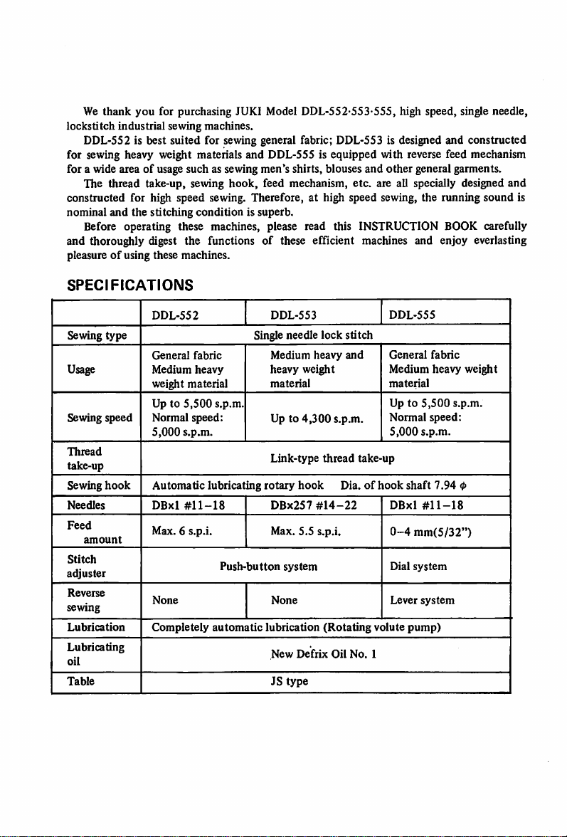
for purchasing JUKI Model DDL-552-553-555, high speed, single needle,
lockstitch
industrial
sewing machines.
DDL-SS2 is best suited for sewing general fabric; DDL-S53 is designed and constructed
for sewing heavy weight materials and DDL-555 is equipped with reverse feed mechanism
for a wide area of usage such as sewing men's shirts, blouses
hook,
The thread take-up, sewing
feed mechanism, etc. are all specially designed
and
other
general garments.
and
constructed for high speed sewing. Therefore, at high speed sewing, the running sound is
nominal
and
the
stitching
condition
is superb.
Before operating these machines, please read this INSTRUCTION BOOK carefully
and thoroughly digest the functions of these efficient machines and enjoy everlasting
pleasureofusing these machines.
SPECIFICATIONS
Sewing
type
Usage
Sewing
speed
Thread
take-up
hook
Sewing
Needles
Feed
amount
Stitch
adjuster
Reverse
sewing
Lubrication
Lubricating
oil
Table
DDL-552
General
fabric
Medium
weight
Up to
heavy
material
5,500
Normal speed:
5,000
s.p.m.
Automatic
DBxl
lubricating
#11-18
Max. 6 s.p.i.
None
Completely
s.p.m.
Push-button
automatic
DDL-553
Single needle
Medium
heavy
weight
material
Up to
4,300
Link-type
rotary
hook
DBx257
Max. 5.5 s.p.i.
system
None
lubrication
New
Defrix
JS
type
lock
heavy
s.p.m.
thread
#14-22
(Rotating
Oil
DDL-555
stitch
and
General
Medium heavy weight
material
Up to
Normal
5,000
take-up
Dia.ofhook
DBxl
0-4
Dial
Lever
volute
No.
1
fabric
5,500
speed:
s.p.m.
shaft
7.94
#11-18
mm(5/32")
system
system
pump)
s.p.m.
<l>
Page 3
TABLE
OF
CONTENTS
(DDL-552-553-555)
Installingtheoil reservoir 2
MotorpuUey and the belt 2
Cautions on operating the machine 3
Lubrication 3
1.
Adjusting
2. TheoUadjusting pin 4
3.
Adjusting
Threading the machine 5
Preparation
Inserting & removing the bobbin case 6
Windingthe bobbin thread 6
How to insert the bobbin 6
The thread tension 7
Adjusting the needle thread tension 7
Thread take-up spring 7
Adjusting the bobbin thread tension 7
Presserfoot and feed dog 8
Adjusting the pressureofthe presser foot 8
The
presser
Height of the feed dog 8
The stitch length 9
Adjusting
Adjusting
Reverse
Inserting
the
Installing
Relation
between
Adjusting
Adjusting
Adjusting
theoil
supply
to the
face
part 4
theoil
supply
to thehook
of
the bobbin thread 6
foot
hand
lifter
the stitch
the stitch length
sewing
length
(DDL-555)
(DDL-552-553)
(DDL-555)
components
needle
and
removing
the
height
the
amount
the
pressing
the
sewing
thehookandtlie
of the
presser
ofthe
thread
pressure
of the
hook
needle
bar
take-up.
feed
lever
(DDL-555)
Page
4
8
9
9
9
12
(Note)
Due to improvements on the machine, some parts of the operationalprocedures
of this INSTRUCTION BOOK might be changed without notice.
- 1 -
Page 4
INSTALLING
Rubber
Operator
side
Oil
THE
cushion
reservoir
OIL
Hinge side
RESERVOIR
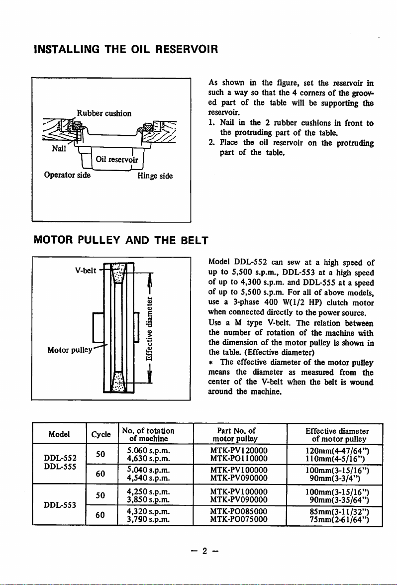
As shown in the flgure, set the reservoir in
such a way so that the 4 comersofthe grooV'
ed part of the table will be supporting the
reservoir.
1.
Nailinthe2rubber
the protruding
cushionsinfront
partofthe table.
to
2. Place the oil reservoir on the protruding
partofthe
table.
MOTOR
Motor
Model
DDL-552
DDL-555
DDL-553
PULLEY
V-belt
pulley
Cycle
50
60
50
60
AND
THE
No.ofrotation
of
machine
5.060
s.p.m.
4,630
s.p.m.
5,040 s.p.m.
4,540
s.p.m.
4,250
s.p.m.
3,850
s.p.m.
4,320
s.p.m.
3,790
s.p.m.
BELT
Model DDL-552 can sew at a high speed of
up to 5,500 s.p.m., DDL-553 at a high speed
of up to 4,300
s.p.m.
and
DDL-555
of up to 5,500 s.p.m. For all of above models,
use a 3-phase
400
W(l/2
HP)
when connected directly to the power source.
Use a M
the
the dimension of the
the
type
V-belt.
numberofrotationofthe
The
motor
pulley is shown in
table. (Effective diameter)
* The effective diameter of the motor pulley
means
the
centerofthe
around
the
Part
No.
motor
pulley
MTK-PVl
MTK-POllOOOO
MTK-PVl
MTK-PV090000
MTK-PVl
MTK-PV090000
MTK-P0085000
MTK-P0075000
20000
00000
00000
diameter
machine.
of
V-belt
as
measured
when
the
Effective
of
120mm(4-47/64")
110mm(4-5/16")
100mm(3-15/16")
90mm(3-3/4")
100mm(3-15/16")
90mm(3-35/64")
85mm(3-ll/32")
75mm(2-61/64")
at a speed
clutch
relation
machine
from
beltiswound
diameter
motor
motor
between
with
the
pulley
- 2 -
Page 5
CAUTIONS
1
Do
not run the
with
fresh
oil.
ON
OPERATING
machine,
under
THE
any
circumstances,
MACHINE
before
theoil
reservoirisfilled
2. Always rotate the machine toward the operator. Do not run the machine in the re
verse
direction.
3.
Although
to
DDL-553at3,800
at an
operator.
normal
appropriate
the
machines
speed
and
s.p.m.
speed
can
attainamaximum
for
DDL-552
and
for
DDL-555at4,500
depending
operate
on the
speed,
for
the
at a
normal
s.p.m.
natureofwork
first
month
speedof4,500
After
that,
and
run
the
capabilityofthe
drop
the
the
speed
s.p.m.,
machines
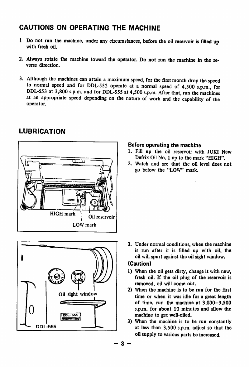
LUBRICATION
Before
operating
1. Fill up the oil reservoir with JUKI New
Defrix Oil No. 1 up to the mark "HIGH".
2.
Watch
and
go
below
the
see
"LOW"
the
that
machine
the
oil level
mark.
does
up
for
not
HIGH
mark
LOW
Oil sight window
IDOL-SSS
•mtrm ntTffI
Oil
reservoir
mark
3.
Under
normal
is
run
oil will
(Caution)
1) When the oil gets dirty, change it with new,
fresh oil.
removed,
2)
When
time or when it was idle for a great length
of
time,
H
- 3 -
s.p.m.
machinetoget
3) When
at less than
oil supply to various parts be increased.
conditions,
after
it is filled up with oil,
spurt
against
If
the oil plugofthe reservoir is
oil will
the
for
the
come
machineistoberun
run
the
about10minutes
well-oiled.
machineistoberun
3,500
when
the
machine
the
oil sight window.
out.
for
the
first
machineat3,000-3,500
and
allow
s.p.m. adjust so
constantly
that
the
the
the
Page 6

Oil
Oil
gets
Z
adjusting
pin
amount
less
II•••''
n I I II
Needle
"Oil
adjusting
\
^
Oil
Counterweight
Crank
amount
If
crank
pin
shaft
adjusting
1^
gets
11
pin
Oil
bar
Grooveofeccentric
Arm
more
screw
1. Adjusting the oil supply to the face
part
When adjusting the oil supply to the thread
take-up and needle bar crank components,
remove
the
face
plate
and
the
oil preventing
plate and adjust by turning the oil adjusting
pin at the tip of the main
1. When
2. When
the
comes
near
less.
the
sideofthe
red
the
red
crank,
(Caution)
The
oil
amount
after
the
adjustment,sowhen
thisinmiiid.
2.
The
oil
adjusting
The oil adjusting pin has a carved groove
1.
as shown in the figure. When this groove
and
the
oil
holeofthe
together, the oil amount gets more.
When
the
red
markonthe
without
groove
the
2.
the oil hole, the oil
The
side
shaft
markofthe adjusting pin
crank,
the
oil
amount
mark
does
comes to
the
oil
not
amount
change
the
opposite
gets
Immediately
adjusting,
pin
main
shaft
is at the oppositesideof
amount
gets less.
oil adjuster shows
carved groove.
gets
more.
have
come
the
Oil regulating valve
3. Adjusting
components
The
supplyofoil to
can be adjusted by
the
hook
1. If this
the
2. If this
amount
- 4 -
oil
shaft.
valve
amount
valve
gets less.
the
oil supplytothe
the
hook
the
oil regulating valve on
is turned toward0
gets
more.
is turned
to0
hook
components
side(right),
side(left), the
Page 7

THREADING
Rotate
the
1.
Pass
2.
Pass
3.
Pull
hand
the
needle
the
thread
out about 10
THE
MACHINE
wheeltoright
thread
in the
to the
needle
cni(4")
and
order
eye
of the
place
shown
from
thread
the
left to
from
thread
by the
right.
the
take-uptothe
flgure.
needle
eye.
highest
position.
(U)
- 5 ~
Page 8

PREPARATION
OF
THE
BOBBIN
THREAD
Bobbin
Trip
case
Adjusting screw
latch
— ^
Thread
Hfii\
f(l!r
Hook
Tension
base
hole
Thread
passinghole
Inserting & removing
1.
Rotate
the
hand
wheel
the
with
bring the needle to its highest position.
2.
Tilt
the machine and support it by tlie head
support
on the table.
3. Lift up the knob of the bobbin case and
takeitout.
*Ifyou
4.
Winding
1.
2.
bobbin
To
into
of
the
of
the
Set
screws.
Pass
hold
will
insert
the
bobbin
hook
the
the
the
shaftoftlie
bobbin
the
knobinopen
not
fall
the
bobbin
case fully
and
then
bobbin
threadinthe
thread
windertothe
off.
case,
hooksothat
close
order
figure and wind it around the bobbin
several
times.
3. Knock down the trip latch and contact the
disc
pulley to the
4. Adjust the winding amount by the winding
belt
adjustingscrewso that about 80%is wound.
5.
When
the
the
threadiswound
thread
tension
disc
correcttoeven winding
6. When the winding is completed, the trip
latch
will be released
stop
automatically.
How
to
1.
Hold
the
case so
condition.
2. Pass the
of
the
3.
Then
the
thread
out
through
insert
the
bobbin
that
the
threadtothe
bobbin
pull the
tension spring and
the
and
bobbin
and
insertitto
thread
case.
thread
anditwill pass under
thread
hole.
bobbin
your
case
hand
and
condition,
insertitdeep
the
the
knob.
table
nose
groove
with
move
and
enters
the
showninthe
unevenly,
basetoleft
condition.
the
pulley will
the
bobbin
will be in
ri^t-twist
thread passing hole
can
be pulled
- 6 -
Page 9
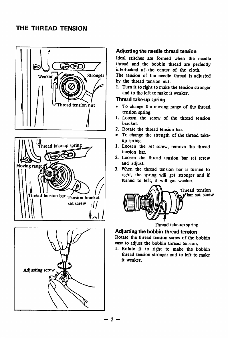
THE
THREAD
TENSION
Weaker
'-'Thread
Ehread
Movingrange
(Tl^ad
take-up
springy
tension
bar
set
Stronger
tension
nut
bracket
screw , / /
Adjusting
Ideal
stitches
the
needle
are
thread
formed
tension
when
the
needle
thread and the bobbin thread are perfectly
interlockedatthe
centerofthe
cloth.
The tension of the needle thread is adjusted
by
the
thread
tension
nut.
1. Turn it to right to make the tensionstronger
andtothe
lefttomakeitweaker.
Thread take-up spring
* To change the moving range of the thread
tension spring:
1.
Loosen
bracket.
2.
Rotate
» To change the strengthofthe thread take-
up spring.
1. Loosen the set screw, remove the thread
tension
2.
Loosen
and
3.
When
right, the spring will get stronger and if
turnedtoleft,
the
bar.
the
adjust.
the
the
screwofthe
thread
thread
thread
tension
tension
it will
tension
get
thread
tension
bar.
bar
set
baristurned
weaker.
Thread
tension
bar
set
screw
screw
to
Adjusting screw
Thread
take-up spring
Adjusting
Rotate
casetoadjust
1. Rotate it to right to make the bobbin
_ 7 -
the
bobbin
the
thread
the
thread tension stronger and to left to make
it
weaker.
thread
tension
tension screwofthe
bobbin
thread
tension.
bobbin
Page 10

PRESSER
FOOT
AND
FEED
DOG
Pressure
screw
0
Hand
hfter
adjusting
Nut
—
Hill
JUKI
N!|^
Adjusting
1.
2.
"
3.
The
To stop the presser
1.
2. The presser foot will go up
(13/64")
3. To
4. With
the
pressureofthe
Turn
the
to
Turn
weaker.
Normal pressure
5 kg (11 lbs).
After
presser
Rotate
part
lifter
downtothe
go up
pressure adjusting screwtoright
make
the
pressure
this
screw to
adjustment,
foot
the
hand
eithertoright or left.
and
stops.
lower
the
presser
once
and
original position.
the
knee
about
10 mm
stronger.
left
to make
for
general fabric is
firmly tighten the
hand
lifter
footatthe
lifterinthe
foot,
activate
the
presser
lifter,
the
presser
(25/64")
presser
foot
the
pressure
about
nut.
lifted position:
rearofthe
about
foot
will
foot
the
face
5 mm
knee
come
will
Feed driving fork
~T7=
Clamp
screw*"
lU
Heightofthe
feed
dog
The height of the feed dog from the surface
the
throat
plate
is set
In sewing light weight materials, if this height is
too
high, shrink-stitching
To
adjust
Loosen
ing
forkofthe
the
the
1.
from0.7-0.8mm(l/32").
may
result.
heightofthe
clamping screwofthe
compound
feed dog:
feed.
2. Move the feed dog base up and down and
adjust
3. After adjusting, tightly tighten the clamping
screw.
Feed
- 8 -
dog
0.7~0.8om
Throat plate
feed
of
driv
Page 11

THE
STITCH
Feed
LENGTH
adjusting dial
Adjustingthe stitch length
(DDL-552-DDL-553)
The stitch lengthofDDL-552
adjusted by the push button ® at the center
of
the upper surface of the arm. Rotate the
hand wheel as you keep pressing down the ®
button.
When the button drops down deep into the
groove of the ratchet (you can feed it) push
down the button further and by rotating the
hand wheel, match the
wanted
(D with the indicator® of the
With this, the length of stitches can be obtained.
The figures on the
hand
numberofstitches per one inch. Release the
push
button
and
verify
to the original position.
The maximum stitch length for DDL-552 is
6 s.p.i. and for DDL-553is 5.5 s.p.i.
Reverse sewing can
(Caution)Donot
not
touch
machine is running.
(DOL-555)
The stitch length of this model can be adjusted
by rotating the feed adjusting dial on top of
the
feed
lever.
The figures on the graduation scale is shown in
millimeter
(mm).
1. Rotate the feed adjusting dial
rightorleft
and
2. Match the wanted figure with the pin
coming
out
from
the
* The maximum stitch length is 4mm(5/32").
number
wheel indicate
that
the
be done.
the
button
frame.
and
DDL-553 is
button
of stitches
frame.
the
returns
while
the
either
to
t
1.DDI--S5SJ
Feed
I
lever
Reverse sewing
(DDL-555)
1. For reverse sewing, push the feed lever
down.
2. As long as this lever is kept down, reverse
- 9 -
sewing can be
3.
Release
turn
to original position and normal straight
stitching can be resumed.
this
performed.
lever
and
the
feed
lever
will
re
Page 12

INSERTING
Set
screw
Needle
THE
NEEDLE
Groove
For
DDL-552
needles
needle.
and
There
and
for
are
DDL-555
DDL-553
many
models,
model,
size
use DBx2S7
numbersofneedles
use
DBxl
but size numbers depend on the thickness of
the using thread or the kinds of sewing cloth.
So, select a correct size and number for your
work.
1.
Rotate
the
hand
wheel
and
bring
the
bar
to the highestposition.
2. Loosen
the
needle clamp screw.
3. Hold the needle so
the
needle
comestoyour
that
the long groove of
left
needle
side.
4. Insert the needle deep into the needle hole.
5. Then securely tighten the needle clamping
screw.
INSTALLING AND REMOVING
r
Set
screw
Bobbin case
finger
positioning
screw
THE
SEWING HOOK
During the running of the machine, if thread
hards get into the hook or the position of the
hook changes for some reason or to exchange
the
hook
order:
1.
Rotate
bartothe
2.
Remove
withanew
the
hand
highest position.
the
one,
do as follows in
wheel and bring the needle
bobbin
case
and
the
needle.
3. Remove the bobbin case base positioning
finger set screw and take out the bobbin
case positioning finger.
4. Loosen the 3 screws
5.
Rotate
the
hand
of
the sewing hook.
wheel
and
raise up
feed base to its highest position.
Rotate
6.
and
the
7. Pull
*
To
the sewing
place it in
figure.
the
hooktoyour
install
the
hook
the
hook
with
position as shown in
left
and
takeitout.
back,
reverse
your
procedure.
the
hand
this
-10
Page 13

RELATION
BETWEEN
Clamp screw
THE
HOOK
AND
THE
NEEDLE
Match
the needle with the
follows:
1. Rotate the hand
bar to its lowest position.
2.
Loosen
the needlebar
(Note)
When
matching the timing of the needle and
wheel
sewing
andbringthe
clamping
set
hook as
needle
screw.
the sewing hook, be sure to set the feed,
adjusting dial to
"0".
(D
DETERMINE
OF
(D
DETERMINE
OF
Needle
Biade
pointy
the
sewing,
hook
THE
THE
THE
NEEDLE
THE
SEWING
(At
the
HEIGHT
BAR
^ Needle bar
lower
bushing
Upper
indicating
Lower
indicating
bar
•
indicating
line
match
pointofthe
hook
the
center
the
needle)
hook
line
with
Needle
POSITION
HOOK
Lower
this
position,
blade
sewing
Sewing
line
(Determine
the
height
of the
3. Match the upper carved line of the needle
bar with the lower edge of the needle bar
lower bushing.
4.
Tighten
(Determine
hook)
the needlebar
the position of the
clamping
5. Loosen the 3 clamping screwsof the hook
so that the hook can be rotated freely with
the
hand.
of
6. Place the
passing position.
7.
Rotate
carved
hook
with your hand to the thread
the
hand
wheel
and
lineofthe
needle
edge of the needle bar lower bushing.
8. In this condition, match the blade point of
the
hook
with
the
center
clearance
between
blade point td
tighten the hook
10.
-11-
9.
Make
and the
Securely
screw.
the
hook
needle
set
match
bar
with
lineofthe
the
O.OS
clamping
screw.
sewing
the
the
needle.
needle
mpi
bar)
lower
lower
and
set
Page 14

ADJUSTING THE HEIGHT OF THE PRESSER BAR
When
the height or the direction of the
presser bar is to be changed due to the
exchangeofpresser foot:
1. Remove the rubber plug of the face plate.
2. From this hole, adjust by loosening the
presser bar clamping screw.
3. After the adjustment, securely tighten the
set
Presser
bar
clamp
screw
screw.
ADJUSTING THE AMOUNT OF THREAD TAKE-UP
The
^
Thread
More
guide
Less
r~/
amount
be changed according to the length of stitches
or thicknessofthe
ideal
thread
1. When sewing heavy weight materiab, move
the thread guide to your left.
The thread take-up amount of the take-up
gets
2. When sewing light weight materials, move
the
The thread take-up amount gets less.
more.
thread
of
tension.
guide to
the
thread take-up should
sewing
clothtoproduce
your
riglit.
ADJUSTING
(DDL-555)
THE
PRESSING
PRESSURE
The reversing spring of the feed lever is
strengthened somewhat so
sewing, no matter what kindofstitches are to
be
original
When
machine istobe
the pressing pressure of the feed lever can be
lessenedbyloosening
the accompanying figure.
-
12
-
formed,
position.
the
OF
THE
the
lever
stitching
FEED
that
returns
pitch
is small or
run
by lowering
the adjusting nut
positively to
LEVER
at high speed
the
when
the
the
r.p.m.,
(T)
of
Page 15

I
lllllll
TOKYO
JUKI
IIKVO
Head
Office&Plant,
Business
Cable
Address:
JUKI
Office:
INDUSTRIAL
2-1,
23.
JUKI
8-chome,
Kabuki
TOKYO
cho,
Kokuryo
Sftiniuku
Telex:
G0..1T0.
cho.
Chofu
ku.
Tokyo.
232-2301
^BEB
shi.
Tokyo.
Japan
JUKISINJUK.U
PrintedinJapan
Japan
TOK
 Loading...