

Page 1
MODEL
HIGH
SPEED.
INDUSTRIAL
EQUIPPED
MODEL
HIGH
SPEED,
LOCKSTITCH
EQUIPPED
MODEL
HIGH
SPEED,
INDUSTRIAL
EQUIPPED
MODEL
HIGH
SPEED,
INDUSTRIAL
EQUIPPED
DDL-552-2-553-2-555-2
SINGLE
NEEDLE,
SEWING
SINGLE
INDUSTRIAL
SINGLE
SEWING
SINGLE
SEWING
MACHINE
NEEDLE,
SEWING
NEEDLE,
MACHINE
NEEDLE,
MACHINE
TOP
DIFFERENTIAL
WITHANAUTOMATIC
DLN-415-2
WITHANAUTOMATIC
DLU-450-2
WITHANAUTOMATIC
DLD-432-2
WITHANAUTOMATIC
LOCKSTITCH
UNDERTRIMMER
NEEDLE
FEED.
MACHINE
UNDERTRIMMER
AND
BOTTOM
UNDERTRIMMER
UNDERTRIMMER
FEED
FEED
Instruction
lIUKI
i
Book
TOKYO
JOKI
INDUSTRIAL
CO.,LTD.
Page 2
CONTENTS
I. GENERAL DESCRIPTION 1
1.
Outstanding
2.
Main
II. HOW TO
1.
2.
3.
4.
5.
INSTALL
Table
Installing
Limit
Lengthofbelt
Installing
6. Installing
7. Installing
Construction
8.
9.
Functionofthe
10.
Howtohandle
11.
Adjusting
III.
HOW
TO
OPERATE
1.
Cautiononoperation
2.
Lubrication
3.
Trial
runofthe
4. How to
5.
Threading
6.
Adjusting
7. Adjusting
8. When low
9.
Carefully
Howtoselect
10.
IV.
ADJUSTING
1.
Adjusting
2.
Adjusting
3.
Howtoinstall
4.
The
floating
5. Flow
6.
7.
8.
9.
10.
11.
V.
DDL-552-2-3
DDL-553-2-3
DDL-555-2-3 DDL-555-2-4
VI.
DDL-555-2-2B
to
Changing
Adjusting
Adjusting
Howtoinstall
Adjusting
In
caseofelectrical
features
specifications
THE
the
motor
of low-speed
the
control
the
machine
the
pedal
and
cord
the
the
clutch
THE
and
machine
operate
the
the
the
the
machine
thread
needle
speed
note
the
the
THE
MACHINE
the
timingofthe
the
positionofthe
the
rangeofthe
sharpen
the
the
the
the
moving
bobbin
slide
and
the
installing
DDL-552-2-4
DDL-553-2-4
DDL-555-2-4B
MACHINE 2
rotationofthe
machine
box
head
and
its
adjustment
operationofmotor
control
box
and
lever
cautions
switch
gap 10
MACHINE
adjusting
the
oiling
amount
pedal
tension
stop
sewing is
following
presser
fixed
knife
position
not
foot,
knife
second
blade
after
thread
trimming
necessary 15
points
throat
plate,
sewing
hook
and
feed
dog
thread
moving
correctly
thread
trimming
knife
tension
cam
disc
knife
thread
presser
shaft
remove
the
angleofthe
malfunctions
knife
installing
synchronizer
base
20
20
21
22
22
23
24
25
27
VII. MALFUNCTIONS AND CORRECTIVE MEASURES , 28
VIII.
IX.
CIRCUIT
DIAGRAM
DIAGRAM,
SHOWING
TIME
METHOD
CHART
OF
ASSEMBLING
TABLE
33
35
1
1
2
2
3
3
3
3
4
5
6
9
11
11
11
11
12
13
13
14
15
15
16
16
17
18
19
Page 3
1.
Outstanding
1)
Simple
By a
simple
sewing,
controlled,
by
foot,
2)
The
electric
3)
All
needle
4)
This
stopping
all
Stable
thread
devicetoproduce
All
attachments
plate,
Dependable
machineisequipped
steppedonfor
pedalisstepped
5)
Compact
All
the
sewing
areaisamply
features
operation
operation
and
worriesofoperational
efficiency
trimming
attachments
slide
safety
high
speed
on.
construction
thread
trimming
wide
of
thread
trimming
movementisinterlocked
constant,
canbeused
which
are
plate,
etc.
device
sewing
mechanisms
and
all
I.
GENERAL
one
pedal,
this
with
utmost
used
tolerances
stable
without
for
are
efficiency.
alterations
conventional
can be used on
withadependable
until
the
thread
are
attachments
canbeused
DESCRIPTION
machine
will
ease.
eliminated.
with
the
lockstitch
this
machine
safety
perform
Also,asthe
rotationofthe
without
device by
trimmingiscompleted
built-in
inside
freely.
the
high
speed
thread
machines,
suchasfeed
any
which
after
bedinrational
sewing,
trimmeriselectrically
machine
and
dog,
low
speed
controlled
presser
alterations.
the
machine
the
cannot
thread
trimming
ordersothat
be
the
2. Main
Sewing
Low-speed
Threads
Sewing
Needles
Motor
Electric
Safety
the
speed
machine
hook
device
specifications
rotation
control
box
DLD-432-2
DLU-450-2
DLN-415-2
DDL-555-2
DDL-552-2
DDL-553-2
of
Cotton
Synthetic
Cotton,
DB
DB
Stop
needle
AMCO
Super
Voltage
Voltage
IC
Built-in
type
x 1
positioner
positioner)
motor
stop
control
Up to
Up to
Up to
Up to
Upto5,000
Upto4,300
thread
thread
synthetic,
automatic
DA
x 1
motor
control
power
system
inside
the
4,200
4,200
5,000
5,000
silk
clutch
DC
AC
motor
s.p.m.(Cotton)
s.p.m.(Cotton)
s.p.m.(Cotton)
s.p.m.(Cotton)
s.p.m.(Cotton)
s.p.m.
Maximum
Maximum
lubricating
motor,
46V,
DC 5V
100,115,
lever
150
120
hook
400W
200,
s.p.m.
s.p.m.
with
(Hitachi
240,
Up to
4,000
Upto4,000
Upto4,000
Upto4,000
Upto4,000
bobbin
clutch
380,
415V
s.p.m.(Synthetic
s.p.m.(Synthetic
s.p.m.(Synthetic
s.p.m.(Synthetic
s.p.m.(Synthetic
thread
guide
motor
with
(All
±10%)
groove
automatic
Fiber)
Fiber)
Fiber)
Fiber)
Fiber)
attached
- 1 -
Page 4
This
machineisequipped
machines.
lever,
trimming
machine
machine.
1.
the
control
mechanism
If
the
will
After
Table
1)
The
the
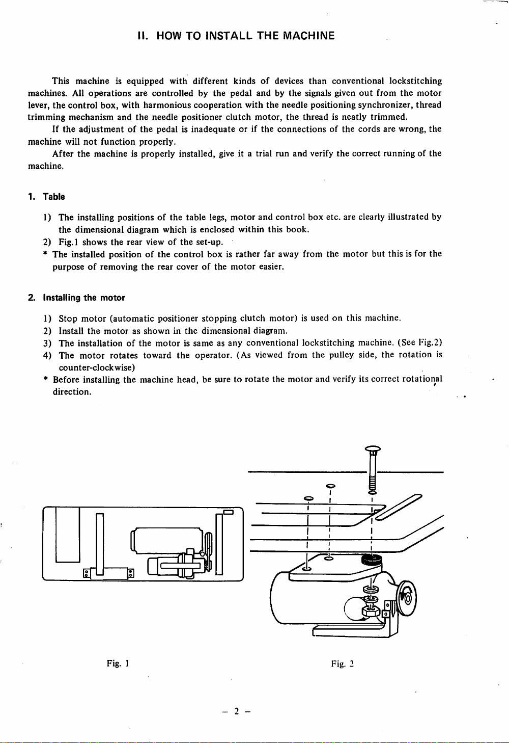
2) Fig. 1
All
operations
box,
with
and
adjustmentofthe
not
function
the
machineisproperly
installing positionsofthe
dimensional
shows
the
diagram
rear
* The installed positionofthe
purposeofremoving
2.
Installing
1)
2)
Stop
Install
the
motor
motor
(automatic
the
motorasshowninthe
3) The installationofthe
4)
The
motor
rotates
counter-clockwise)
*
Before
installing
direction.
the
II.
HOW
TO
with
different
are
controlled
harmonious
the
needle
pedalisinadequateorif
properly.
by
cooperation
positioner
installed, give it a trial
table
whichisenclosed
viewofthe
set-up.
control
the
rear
coverofthe
positioner stopping
dimensional
motor
is same as any conventional lockstitching machine. (See Fig.2)
toward
machine
the
operator.
head,besure
INSTALL
kindsofdevices
the
pedal
with
clutch
legs,
motor
within
boxisrather
motor
clutch
(As viewed
to rotatethe
THE
MACHINE
than
andbythe
the
motor,
the
and
this
signals given
needle
the
threadisneatly
connectionsofthe
run
and
control
box
book.
far away from the
easier.
motor)
diagram.
is used on this machine.
from
motor
conventional
positioning
verify
the
etc.
are clearly
motor
the
pulley side, the
and
verify
out
from
synchronizer,
trimmed.
cords
are
correct
runningofthe
illustrated
but
this is for the
its
correct
lockstitching
the
motor
thread
wrong,
the
by
rotation
rotationjal
is
I I
Fig.
1
- 2 -
Fig.
Page 5
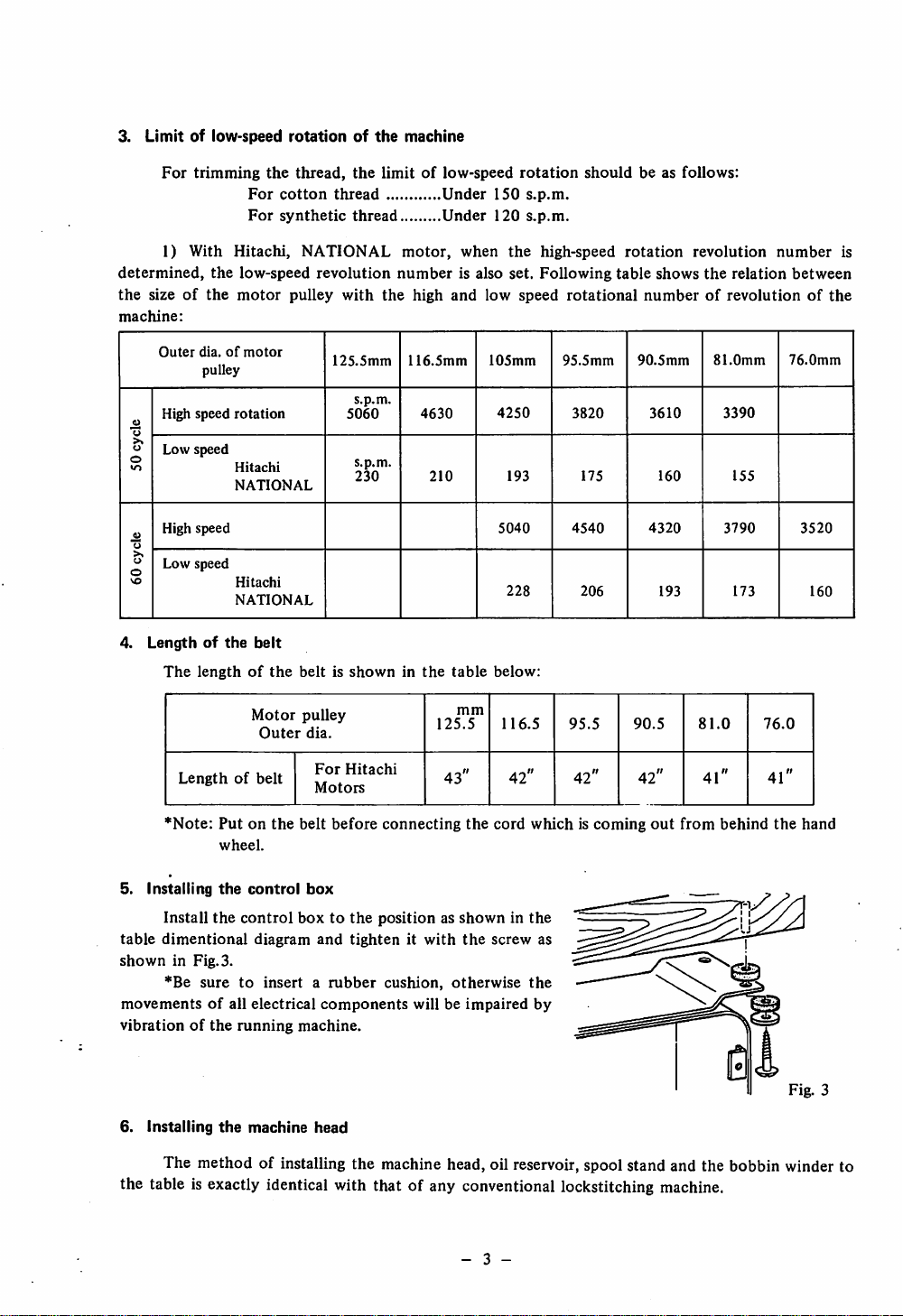
3.
Limitoflow-speed
For
trimming
rotationofthe
the
thread,
For
cotton
For
synthetic
the
limitoflow-speed
thread
thread
machine
Under
Under
150
120
rotation
s.p.m.
s.p.m.
should
be as follows:
1) With
determined,
the
sizeofthe
machine:
Outer
High
.H
o
Low
o
lO
High
•3
u
Low speed
0
ve
4.
Lengthofthe
The
Lengthofbelt
Hitachi,
the
low-speed
motor
dia.ofmotor
pulley
speed
rotation
speed
Hitachi
NATIONAL
speed
Hitachi
NATIONAL
belt
lengthofthe
Motor
Outer
NATIONAL
revolution
pulley
with
125.5mm
5060
s.p.m.
s.p.m.
230
motor,
number
the
116.5mm
beltisshowninthe
pulley
dia.
For
Hitachi
Motors
high
4630
210
and
table
125.5
43"
when
the
high-speed
is also
set.
Following
low
speed
105mm
4250
193
5040
228
below:
mm
116.5
42" 42" 42"
rotational
95.5mm
3820
175
4540
206
95.5
rotation
table
shows
revolution
the
relation
number
numberofrevolutionofthe
90.5mm
3610
160
4320
193
90.5
81.0mm
81.0
41"
3390
155
3790
173
76.0
41"
is
between
76.0mm
3520
160
*Note:
5.
Installing
Install
table
dimentional
shown
*Be
movementsofall
vibrationofthe
6.
Installing
Putonthe
wheel.
the
the
control
belt
control
boxtothe
diagram
in Fig. 3.
suretoinsertarubber
electrical
running
the
machine.
machine
before
box
and
tightenitwith
components
head
connecting
the
cord
whichiscoming
positionasshowninthe
the
screw
cushion,
will be
otherwise
impaired
the
by
out
from
behind
as
The method of installing the machine head, oil reservoir, spool stand and the bobbin winder to
the table is exactly identical with that of any conventional lockstitching machine.
- 3 -
the
hand
Fig. 3
Page 6
7. Installing
the
pedal
and
Its
adjustment
In case of motor lever switch type, installation of the pedal and its adjustment is very simple.
1) 1)
Installing
positionofthe
pedal
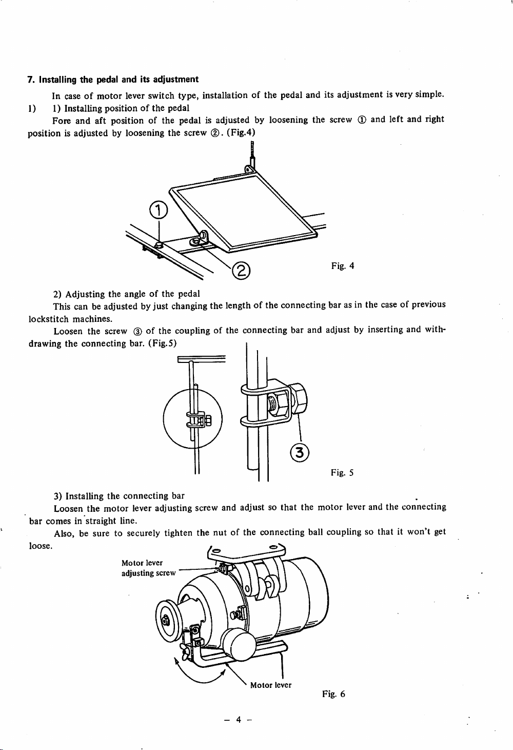
Fore and aft position of the pedal is adjusted by loosening the screw (I) and left and right
position is adjusted by loosening the screw
2) Adjusting the angleofthe pedal
(2).
(Fig.4)
Fig. 4
This can be adjusted by just changingthe length of the connecting bar as in the caseof previous
lockstitch
drawing the connecting bar. (Fig.5)
machines.
Loosen the screw
(3)
of the coupling of the connecting bar and adjust by inserting and with
ss
Fig. 5
3) Installing
Loosen the motor lever adjusting screw and adjust so that the motor lever and the connecting
bar
comesinstraight
Also, be sure to securely tighten the nut of the connecting ball coupling so that it won't get
loose.
the
connecting
line.
Motor
adjusting screw
lever
bar
- 4 -
Motor
lever
Fig. 6
Page 7
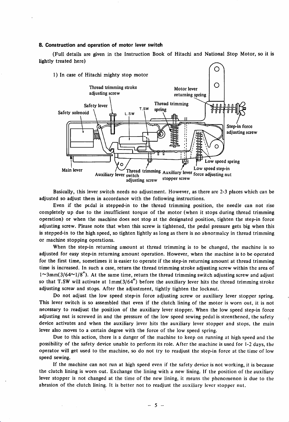
8.
Construction
(Full
lightly
treated
and
operationofmotor
details are given in
here)
the
Instruction
lever switch
BookofHitachi
and
National
Stop
Motor,
so it is
1) In caseofHitachi
Safety
Safety
solenoid
Main
lever
Basically,
adjustedsoadjust
Even if
completely
operation)orwhen
adjusting screw. Please
is
stepped-intothe
or
machine
When
adjusted
for
the
first time, sometimes it is easier to operate if the step-in returning amount at thread trimming
time
is increased. In
this
theminaccordance
the
pedal is stepped-in to
up
duetothe
high
stopping
the
step-in
for easy step-in
l~3mm(3/64~l/8"). At the sametime,return the thread
T.SW
will
so that
adjusting
screw
activate at lmm(3/64") before the auxiliary
and
mighty
Thread
trimming
adjusting screw
lever
Auxiliary
lever
switch
insufficient
the
machine
note
that
speed,sotighten
operations.
returning
returning
such
a case,
stops.
After
stop
motor
stroke
Thread trimming
tsw
L.SW
/^Thread
lever
switch
adjusting
needsnoadjustment.
with
torqueofthe
does
not
when
this screw is
amount
amount
return
the
the
adjustment,
spring
trimming
screw
the
following
the
thread
stopatthe
lightlyaslongasthere
at
thread
operation.
thread
tightly
Motor
lever
returning
Auxiliary
Auxiliary
stopper
However,asthere
instructions.
trimming
motor
designated
tightened,
trimmingistobechanged,
However, when
trimming
trimming
tighten
spring
lever
r
lever
force
screw
position,
(whenitstops
position,
the
pedal pressure gets big
is no
abnormalcyinthread
stroke
adjusting
switchadjusting
lever
hits the thread trimming stroke
the
locknut.
adjusting
the
Step-in force
adjusting screw
speed
spring
nut
are 2-3
places
the needle can
during
thread
tighten
machine istobe
screw
the
the
within
screw
which
not
trimming
step-in
when
trimming
machine
operated
the
and adjust
can be
rise
force
this
is so
area
Do not adjust the low speed step-in force adjusting screw or auxiliary lever stopper spring.
This lever
switch
is so assembled
that
even if the
clutch
liningofthe
motorisworn
out,
it is
not
necessary to readjust the position of the auxiliary lever stopper. When the low speed step-in force
adjusting
device activates and when the auxiliary lever hits the auxiliary lever
lever also moves to a certain degree
nut
is screwed in
and
the
pressureofthe low speed sewing pedal is
with
the
forceofthe low speed spring.
stopper
strenthened,
the
and stops, the main
safety
Due to this action, there is a danger of the machine to keep on running at high speed and the
possibilityofthe
operator
speed
will get used to
sewing.
safety
device unable to
the
machine,
perform
so do
not
its role.
try
to readjust
After
the machine is used for 1-2 days,
the
step-in force at
the
timeoflow
the
If the machine can not run at high speed even if the safety device is not working, it is because
the
clutch
lining is
worn
out.
Exchange
the
lining
with
a new lining. If the positionofthe auxiliary
lever stopper is not changed at the time of the new lining, it means the phenomenon is due to the
abrasion of the clutch lining. It is
better
not
to readjust the auxiliary lever
stopper
nut.
of
- 5 -
Page 8
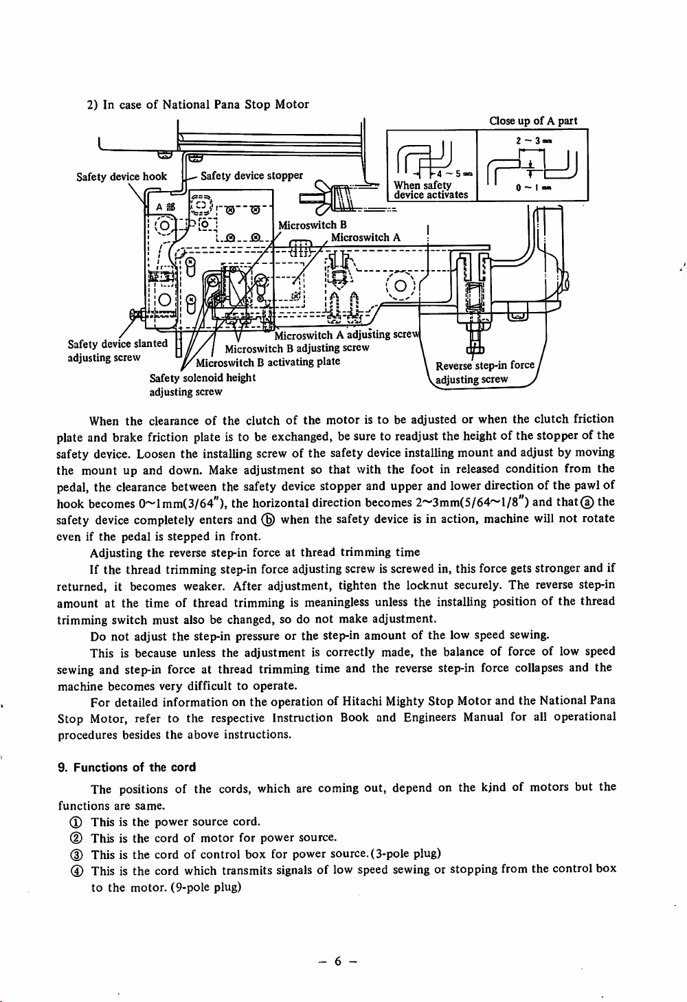
2)IncaseofNational
Pana
Stop
Motor
GoseupofApart
Safety
device
hook
\
Safety device slanted
adjusting
When
screw
Safety
adjusting
the
clearanceofthe
Safety
device
stopper
Microswitch
Microswitch B adjusting screw
Microswitch B activating
solenoid
height
screw
MicroswitchAadjusting
clutchofthe
When
device
B
Microswitch
plate
motoristobeadjustedorwhen
A
screw
5
safety
activates
Reverse step-in force,
adjusting screw y
the
clutch
friction
plate and brake friction plate is to be exchanged, be sure to readjust the heightof the stopper of the
safety device. Loosen the installing screw of the safety deviceinstalling mount and adjust by moving
the mount up and down. Make adjustment so that with the foot in released condition from the
pedal,
the
hook
safety
even if
clearance
becomes
device
the
pedalisstepped
Adjusting
between the safety
0~lmm(3/64"),the
device
horizontal
stopper and upper and lowerdirectionof the
direction
completely enters and ® when the safety
in front.
the
reverse step-in force at thread trimming time
becomes
device
pawl
2~3mm(5/64~l/8")andthat@ the
is in action,
machine
will not rotate
of
If the thread trimming step-in force adjusting screw is screwed in, this force gets stronger and if
returned, it becomes weaker. After adjustment, tighten the locknut securely. The reverse step-in
amount at the time of thread trimming is meaningless unless the installing position of the thread
trimming switch must also be changed, so do
not
make adjustment.
Do not adjust the step-in pressure or the step-in amount of the low speed sewing.
This is because unless the adjustment is correctly made, the balance of force of low speed
sewing and step-in force at thread trimming time and the reverse step-in force collapses and the
machine
becomes
very difficult to
operate.
For detailed information on the operation of Hitachi Mighty Stop Motor and the National Pana
Stop Motor, refer to the respective Instruction Book and Engineers
procedures
besides
the
above
instructions.
Manual
for all operational
9.
Functions
of
the
cord
The positions of the cords, which are coming out, depend on the kjnd of motors but the
functions
(3)
d)
(3) This is
are
same.
Thisisthe
power
This is the cord of
the
cord of control box for power source. (3-pole plug)
source
motor
cord.
for power source.
® This is the cord which transmits signals of low speed sewing or stopping from the control box
to
the
motor.
(9-pole
plug)
- 6 -
Page 9
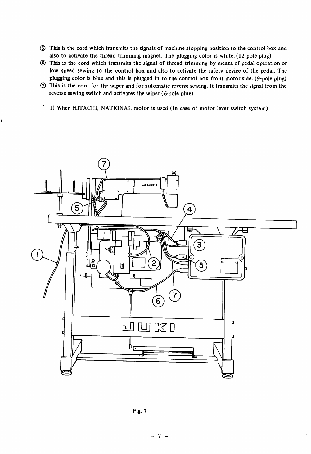
(D This is the cord which transmits the signalsofmachine stopping position to the control box and
alsotoactivate
the
thread
trimming
magnet.
The
plugging
coloriswhite.
(I2-pole
plug)
(D This is the cord which transmits the signal of thread trimming by means of pedal operation or
low
speed
sewingtothe
plugging
color
is blue and this is plugged in to
(?) This is the cord for the wiper and for automatic reverse
reverse sewing
switch
and
control
activates
box
the
and
alsotoactivate
wiper
(6-pole plug)
the
control
sewing.
the
safety
deviceofthe
box
front
motor
side. (9-pole plug)
It transmits the signalfrom the
pedal.
The
1) When HITACHI, NATIONAL
motor
•JUKI
is used
(In
caseofmotor
lever switch system)
[-flCLOKD
Fig.
7
- 7
Page 10
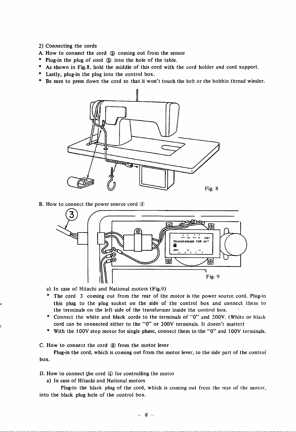
2)
Connecting
A.
Howtoconnect
* Plug-in
* As
showninFig.8,
the
the
plugofcord
* Lastly, plug-in
* Be suretopress
cords
the
cord(Dcoming
hold
the
plug
down
(§)
into
the
the
middleofthis
into
the
control
the
cordsothatitwon't
out
from
holeofthe
cord
box.
the
table.
with
touch
sensor
the
the
cord
holder
beltorthe
bobbin
Fig. 8
and
cord
thread
support.
winder.
B. How to
connect
a) In caseofHitachi
*
The
cord 3
this plug
the
terminals
*
Connect
cord
canbeconnected
*
With
the
C.
Howtoconnect
Plug-in
the
box.
D.
Howtoconnect
a) In
caseofHitachi
Plug-in
into
the
black
plug
to
the
lOOV
cord,
the
the
power
and
coming
the
on
white
the
stop
the
out
plug
left
and
motor
cord
whichiscoming
the
cord0for
and
National
black
plugofthe
holeofthe
source
cord (J)
National
socket
black
eithertothe
(6)
motors
from
the
on
sideofthe
cordstothe
for
single
from
the
controlling
motors
control
(Fig.9)
rearofthe
the
sideofthe
transformer
"0"or200V
phase,
motor
out
from
the
cord,
whichiscoming
box.
TRAKSFORMER
a
*»r
/ / 1 V \
motoristhe
control
inside
terminalsof"0"
terminals.Itdoesn't
connect
lever
the
motor
motor
themtothe
lever, to
»•
the
out
m
xai
f^OR
ATr
Fig.
power
box and
control
and
"0"
the
side partofthe
from
9
source
box.
200V.
and
the
rearofthe
connect
matter)
cord.
Plug-in
them
(Whiteorblack
lOOV
terminals.
control
motor,
to
- 8
Page 11
10.
Howtohandle
the
control
box
and
cautions
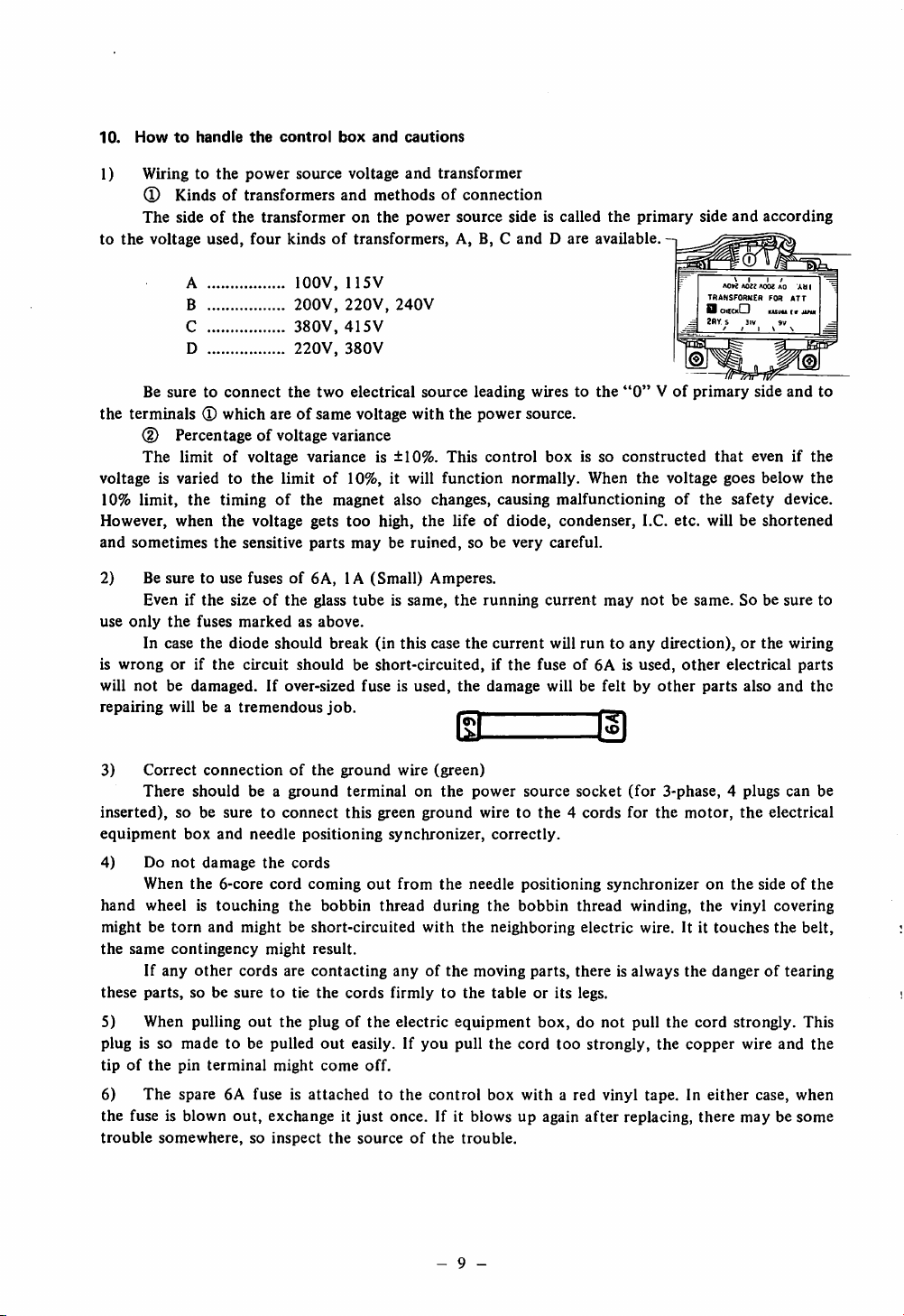
1) Wiring to
the
power
(D Kindsoftransformers
The
sideofthe
to
the
voltage
A lOOV,
B
C
D
Be
suretoconnect
the
terminals®which
used,
transformer
four
kindsoftransformers,
the
areofsame
(D Percentage of voltage variance
The
limitofvoltage
voltage is varied to
10%
limit,
the
However, when
and
sometimes
2) Be
use
is
will
repairing
sure
Evenifthe
only
the
In
case
wrongorif
notbedamaged.
will
the
limitof10%, it will
timingofthe
the
voltage gets
the
sensitive
to use fusesof6A,1A(Small)
sizeofthe
fuses
markedasabove.
the
diode
should
the
circuit
If over-sized
be a
tremendous
source voltage
and
and
transformer
methodsofconnection
on
the
power
source
A, B, C
115V
200V,
220V,
240V
380V,
415V
220V,
380V
two
electrical
voltage
varianceis±10%.
source
with
the
This
leading
power
control
function
magnet
parts
also changes, causing
too
high,
the
mayberuined,
life of diode, condenser, I.C. etc. will be
so be
Amperes.
glass
tubeissame,
break
(in
this
case
the
the
running
current
shouldbeshort-circuited,ifthe
fuseisused,
job.
the
damage
Ht
sideiscalled
andDare
wires to
the
available.
the
source.
box
is so
normally.
When
malfunctioningofthe
very
careful.
current
will
may
runtoany
fuseof6A is
will be
feltbyother
primary
"0"Vof
constructed
the
notbesame.Sobe
side
A0>? A022 AOOZAO Ati I
TRANSFORMER
D
oicckIZI
2RY.S 3IV 9V
primary
that
voltage goes
direction),orthe
used,
other
parts
and
according
VI
I /
FOR
kuiiu
side
evenifthe
below
safety
shortened
electrical
also
ATT
!• Jin
and
device.
sure
wiring
parts
and
to
the
to
the
Correct
3)
There
inserted),
equipment
4) Do
so be
not
When
hand
wheelistouching
mightbetorn
the
same
contingency
If
any
these
parts,
5)
When
plug is so
tipofthe
6)
the
trouble
madetobe pulled
pin
The
spare 6A fuse is
fuse is blown
somewhere,
connectionofthe
should
be a
suretoconnect
box
and
needle
damage
the
and
other
so be
pulling
terminal
the
6-core
cord
mightbeshort-circuited
might
cords
suretotie
out
the
might
out,
exchange it
so
inspect
ground
positioning
cords
coming
the
bobbin
result.
are
contacting
the
plugofthe
out
come
attached
ground
wire
terminalonthe
this
green
synchronizer,
out
from
thread
anyofthe
cords
firmlytothe
electric
easily. If
off.
to the
just
once. If it blows up again
the
sourceofthe
(green)
ground
the
during
with
you
control
- 9 -
power
source
socket
wiretothe4cords
correctly.
needle
the
the
neighboring
moving
tableorits
equipment
pull
the
positioning
bobbin
parts,
box,donot
cord
synchronizeronthe
thread
electric
there
is always
legs.
too
strongly,
box with a red vinyl tape. In
after
trouble.
(for
3-phase,4plugs
for
the
motor,
winding,
wire. It it
the
pull
the
the
copper
replacing,
the
electrical
sideofthe
the
vinyl
covering
touches
the
dangeroftearing
cord
strongly.
wire
and
either
case, when
there
maybesome
can
be
belt,
This
the
Page 12
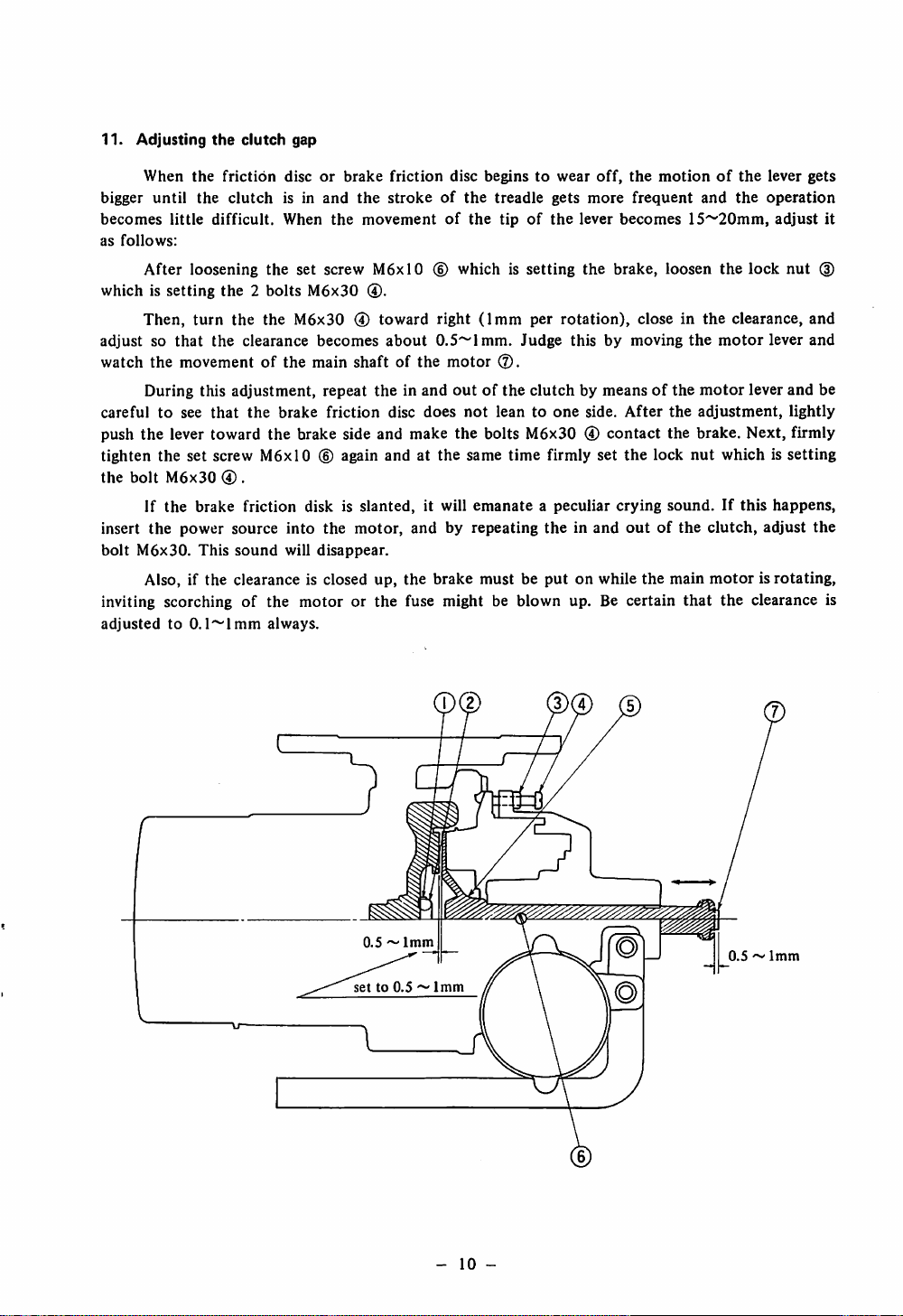
11.
Adjusting
When
bigger
until
becomes
as
follows:
After
which is
Then,
adjustsothat
watch
the
During this
carefultosee
push
the
tighten
the
bolt
If
insert
the
bolt
M6x30.
the
the
the
little
difficult.
loosening
setting
turn
the
movement
that
lever toward
the
set
screw
M6x30
the
brake
power
This
clutch
friction
clutch
discorbrake
is in
When
the
the2bolts
the
the
clearance
of
the
adjustment,
the
brake
the
M6xl0
0 .
friction
source
into
sound
will
Also, if the clearance is closed up,
inviting scorching of the
adjustedto0.l~lmm
always.
gap
friction
and
the
strokeofthe
the
movementofthe
set screw
M6x30
M6xl0
0.
M6x300toward
becomes
main
repeat
friction
about
shaftofthe
theinand
disc
disc
beginstowear
(D which is
right
(1mm
0.5~lmm.
motor
outofthe
does
not
treadle
gets
tipofthe
setting
per
rotation),
Judge
clutchbymeansofthe
leantoone
brake side and make the bolts M6x30 0
® again
disk is
the
disappear.
motor
and
slanted,
motor,
at the same
it will
and
by
the
brake must be
time
firmly
emanateapeculiar
repeating
theinand
put
or the fuse might be blown up. Be certain
off,
the
motionofthe
more
frequent
lever
becomes
the
brake,
loosen
close in
thisbymoving
side.
After
the
contact
set
the brake. Next, firmly
the
lock
crying
sound.Ifthis
outofthe
on while
the
and
the
15~20mm,
the
the
clearance,
the
motor
motor
adjustment,
nut
whichissetting
clutch,
main
motorisrotating,
that
the
lever
gets
operation
adjust
lock
nut
and
lever
and
lever
and
lightly
happens,
adjust
the
clearance is
it
(3)
be
0.5~1mm
setto0.5~1mm
-
10
-
0.5^1mm
Page 13

I.
HOW
TO
OPERATE
1.
Cautionsonoperation
Turn
the
switchononce
direction
* Unpack
* Before
* Do
*
*
of
the
machine.
the
machine
operating
BOOKonDDL-552,
not
run
the
The
machine
counter-clockwise).
For
the
first
should
month,
s.p.m. for DLN-415-3
increase
* When
*
When
* When
the
the
the
the
speed
power
power
machine
* If the needle does
turn
the
switch
this
machine
Do
dependingonthe
switchisturned
switchisturned
head
not
off.
and
machine,
553
without
rotate
not
drop
and
has to be
stop
THE
and
after
settingitup,
and
555orDLN-4I5,
toward
run
the
the
speedto4,500
3,800
at the
* When transporting the machine, do
* Sometimes when the
pedal to the rear
cannotbedone.Insuch
down
and
normal
power
immediately
a case,
trimming
canberesumed.
switch is
after
just
MACHINE
after
turningitoff,
steponthe
clean it well.
please
read
and
digest
DLU-450,
filling up
the
machineinthe
s.p.m.
on,donot
on,donot
tilted
top
not
the
oil reservoir,
operator.
(As
reverse
s.p.m.
viewed
for DDL-552-3
for DDL-553-3, DLU-450-3
natureofwork
put
touch
for
oilingorcleaning,besuretoturn
your
the
and
hands
position even when the pedal is
touch
the cover on
turned
on and the thread is
these actions, the needle will
steponthe
pedal
toward
every
paragraphofthe
DLD-432
from
direction.
the
capabilityofthe
around
hand
wheel.
the
rear partofthe hand wheel.
front
pedal
and
observe
thoroughly.
the
pulley
and
DDL-555-3
and
DLD-432-3.
and
under
steppedontoward
trimmed
not
once
come
and
butifyou
the
the
INSTRUCTION
side,
the
operator.
the
needle parts.
the
switch
steponthe
down
and
needle
rotational
direction
and
4,300
After
that,
off.
the
rear,
trimming
will
come
is
2.
Lubrication
Before
machine oil to
separate
3.
Trial
and
running
the
instruction
runofthe
adjusting
the
"HIGH"
volume.
machine
the
oiling
amount
machine, fill up the oil reservoir
mark. Please refer to
the
chapteron"Lubrication
with
the
designated
and
JUKI
drainage"onthe
* At first, verify the correct movement of the machine without passing the thread.
1) When the power switch is turned on, the needle always stops at the raised position. In case
the needle does not
measures"
and
2)
Step
If the machine does not function even after these re-adjustments, refer to the
functions
to
ascertain
3)
and
After
that
stop
make
at the raised position, refer to the
proper
adjustment.
chapter
on "Malfunctions and corrective
on the pedal lightly toward front and verify the correct low speed sewing operation.
chapter
corrective
the pedal is
the
measures".
steppedonfront
machine
stops
with
(away
from
the
needleatlower
the
operator)
position.
and
the
foot
is released, be sure
industrial
on "Mal
- 11 -
Page 14

4) Step on the pedal toward rear and verify the thread trimming operation.
5) Re-adjusting the low-speed switch and verifying the correct working of the safety
device.
Step on the pedal toward rear (the thread trimming switch will start) and if you hear the sound
of the magnet working from under the bed, immediately step on the pedal toward front.
If these movements are repeated over and over again, invariably there willbea position where
the pedal will not move toward front any more. At this position, the machine will be stopping but
if the machine should
machineatthis
6) Insert the needle and start sewing.
Note:
*"Front"
*"Rear"
4.
Howtooperate
As
shown
move
position.
means
means
the
pedal
in Fig. 10,
for
low-speed
away
toward
the
pedalofthis
from
the
sewing,
the
operator
operator
machine
re-adjust the
functions
low-speed
in 4 stages as follows:
sewing
switch to stop the
(D The machine is stopping by just resting your foot lightly on the pedal.
(D
When
(D
®
the pedal is stepped on lightly to front, it
When
the pedalis stepped on further
When
the pedal is stepped on
fully
strongly
toward rear, the
becomes
to front, it
machine
low-speed
becomes
will
sewing.
high
speed
sewing.
perform thread
trimming.
* Normal thread trimming can be performed even if the pedal is stepped on abruptly to the rear
either
from
high
speedorlow
speed
sewing.
* After the machine has started the trimming, the trimming can be done even if the pedal is returned
to
the
needle
neutral
goesupand
position.Itis
stops.
not
necessarytokeeponsteppingonthe
pedaltothe
rear
until
the
High
" ~
speed
Low
speed
^Stopped
Thread trimming
-
12
position
HIGH
SPEED
LOW
SPEED
STOPPED
POSITION
THREAD
TRIMMING
Fig.
10
-
Page 15

♦
When
the
machine is
* If the lowered needle is to be raised up again,
and
stops
after
(Caution)
the
stopped,
trimming
the
needle always comes
action.
down
and stops.
step
on the pedal toward rear fully. Needle goes up
After completing the trimming (stepping the pedal to rear), if you try to step on the pedal to
front suddenly, sometimes the pedal will not move. This is because the safety device inside the pedal
is acting to prevent any undue damage to the machine. In such a case, return the pedal to the rear
once and then step on the pedal toward front once more and the machine will start its normal
running.
5.
Threading
*The
ing the machine, step on the pedal toward rear once and do
needle
*Pass
6.
Adjusting
Adjusting
machine. Please follow
and
555,
attachedtothis
the
needle always
willgoup
the
needle thread in
the
DLN-415,
machine
stops
at the raised position. But if it is at
and
stops
there.
the
thread
tension
the
thread
the
DLU-450orDLD-432.
machine,
(Fig.28)
tensionofthis
procedures as
the
adjustmentislittle
orderof(T)
outlined
However, please
the
lowered position when
the
trimming action once. Then
~ ® as shown in Fig.27.
machineisexactly
in the INSTRUCTION BOOK on DDL-552, 553
different
than
note
other
like a
that
conventional
duetothe
lockstitch
thread
machines.
thread
the
lockstitching
trimmer
^ First tension disc
WeakIStrong
(Adjusts
the
thread
remaining at
the
needle
trimming >
(4)
Strong
w
Second
(adjusts
tention)
Fig.
Weak
11
-
13
-
Fig. 12
length
of)
eye
after
tension
disc
the
thread
Page 16

1)
Thread
When fine
take-up
cotton
spring
thread or synthetic threads (tetoron, nylon etc.) are used, the tension of the
take-up spring may become too strong or the range of movement of the spring may become too wide,
causing skip-stitching
thread.
Be
extremely
2)
Adjusting
*When
the tension of the first thread tension is made stronger, the thread remaining at the tip of
just
careful.
the
first
before
thread
the
tension
machine
disc
stops
and
sometimes
the
machine
does
not
trim
the
the needle eye becomes shorter after trimming and when it is made weaker, the remaining thread
becomes
longer.
*For fine tlireads (synthetic fiber), weaken the tension and for thick thread, make it stronger.
3)
Adjusting
* Normally, the adjustmentofthis disc is same as any
* However, please
the
thread
might
4)
Adjusting
The
adjustment
the
second
note
breakatthe
the
bobbin
of the
thread
tension
other
lockstitching machines.
that
when synthetic thread is used, if the tension is adjusted
startofsewing.
thread
tension.
bobbin
thread
tension is practically
sameasany
conventional
too
weak,
lockstitch
ing machine. However, if the tension is too weak, the bobbin might spin idly at the trimming instant,
causing the needle thread to
"float"
up at the
start
of sewing, and for synthetic threads, thread
breakage or slipping out of the needle thread at the start of sewing might occur. Be very careful.
* As a rule, this machine is used with a bobbin case in which a magnet is built-in to prevent
idle spinning of the bobbin. (Part number is D 1837555 BAO and sold separately)
7. Adjusting
the
standard
control box) to right and left so that, after the thread is trimmed and
red
mark
standard
will
stop
the
needle
stop
position after thread trimming (Fig.13)
After the thread is trimmed, this machine can change
needle
on
the
If the adjusting
stopping
below
* If the thread should slip
stop
arm
and
knobisrotated
position,
the
white
rotate
mark
toward the
position (in caseofA) and if
the
standard
stopping
out
position
even if the length of needle thread is adjusted
the
on
needle
the
it's
(in
position
hand
wheel
"FAST"
rotated
caseofB).
the
needle
stop
position.Toadjust to
adjusting
are
matched
knob®(on
the
needle has stopped,
with
each
direction, the needle will
toward
the
"SLOW"
direction,
the
other.
stop
after
sideofthe
above the
the
the
is trimmed, rotate the adjusting knob toward the "SLOW" direction, (toward [B] direction).
* If the needle should hit the wiper, rotate the knob toward the
[A]
direction).
(Caution)
"FAST"
direction, (toward
If the adjusting knob is rotated too much toward the "SLOW" direction (toward B direction),
sometimes
the
machine
does
not
stop.Insuch
a case
rotate
the
knob
toward
the
"FAST"
direction.
iBl [A]
o
"SLOW"
Adju-sting
T7T777T7T77-
knob
Standard
stop
position
"777V7/////
Throat
needle
•
plate
^?^"FAST"
Adjusting
y
knob
Fig.
13
the
needle
thread
-
14
-
Page 17

8. When low speed sewing is not necessary (Fig.14)
* Be sure to cut off the power and make adjustment. When low speed sewing is not necessary
at
the
startofsewing;
(2)
Cut
off
the
power
source.
(2)
Open
the
coverofthe
control
box.
(D Pull out the inserted ® of the figure from the pin @ and insert it into the pin lij.
Thus, the low speed
function.
sewing
function can be eliminated without affecting the thread trimming
r
Fig.
14
9.
Carefully
the
remaining
might
break.Insuch
* Be
result.)
*
When
note
the
certain
thread
skip-stitching
a case,
following
that
the
at
re-adjust
the
points
needle
needle
occurs,
the
thread
comes
eye
after
the
bobbin
timingofthe
out
trimming
thread
needle
smoothly
will
may
with
from
become
break
the
sewing
but
the
short
thread
the
hook.
and
needle
spindle.
thread
thread
(Otherwise,
slipping
does
out
not
10. Howtoselect
1)
Presser
2)
Throat
3)
Needle
4)
Sewing
5)
Feed
but
if an
extremely
the
moving
dog
knife
1)
2)
the
foot
plate
hook
moves
Presser
Throat
presser
thick
foot
plate
feed
fully.
foot,
throat
Select
smallaandbparts
Select
small
Finer
needle
Automatic
If a
feed
dog
dogisused,
plate, sewing
needle
eye
andApart.
for
less
thread
lubricating
whichiscommonly
the
hook
backsideofthe
hook
and
(Fig.
15)
slippage
withagroove
usedisadopted,
feed
dog
dog
teeth
mightbescratched
thereisno
Na
Fig.
15
-
15
-
problem,
when
Page 18

IV.
ADJUSTING
THE
MACHINE
This machine consists of lockstitching part and the thread trimming part. The lockstitching
function is same as all other previous models, so this text will cover the thread trimming part only.
1. Adjusting
the
timingofthe
1) Howtojudge
In
order
to change
the
timingofthe
indicated
Tilt
before
the
lineonthe
the
upper
thread
hand
machine,
dead
cam roller (Fig.17) will
that
condition,
hand
wheel
matchedsothat
(Fig.
18 (D)
will
are
rotate
cometoa
the
indicated
matched
indicating line (Fig. 18
synthetic
thread.
thread
trimming
the
correct
the
timingofthe
lengthofthe
thread
trimming cam. This can be
wheel,
accordingtothe
turn
the
hand
wheel
point
and if
the
sewing
enter
the
cam
grooveofthe
the
hand
wheelinthe
point
where
it will
lineofthe
togetherasshown
®)ismatched
a
arm
in Fig.
with
(Z
cam
trimming
cam
remaining at the needle eye
done
easily by matching the arm with
kindofthread
with
your
hand
until
hook
presser (Fig. 16 (D) is pushed deeply to right, the
cam (Fig. 17)
reverse
(Fig.18 (D)
the
Thread
cam
direction
not
rotate
any
more.Atthis
and
the
18,itbecomesacotton
indicating
line (Fig. 18 (D), it
trimming
used-cotton
the
and
than
the
indicated
after
thread
will be
interlocked
conventional
pointifcam
lineofthe
thread
becomes
Rotational
trimming,
or
synthetic
take-up
timing.
comes
way,
hand
Butifthe
a timing
direction
adjust
the
thread.
Just
there. In
and
the
timing
wheel
for
is
2)
Howtomatch
First,
No.2,
and
cotton
thread,
the
green
Then,bypushing
roller,
and
normal
not
finally
hook
rotate
tighten
loosen
match
color
without
any
Fig. 16
match
(D),
shaft
more,
the
DLD-432-2
the
the2set
the
indicating
red
(Fig.
the
rotating
rotational
push
cam
set
timingofthe
screwsofthe
lineofthe
color
(i)
18)
sewing
the
hook
direction
the
screws
with
hook
cam
(Fig.
thread
trimming
the
presser
shaft,
with
against
17)inthe
Cam
arm
red
rotate
your
-
Cam
arm
color
the
16
roller
roller
shaft
set
screw
trimming
cam
(Fig.
with
the
(2)
and
(Fig.
16 (3))toright,
the
cam
only
finger tips. At
thread
orderofNo.2
trimming
-
cam
17)inorder
indicating
for
synthetic
toward
and
Rotate
direction
Fig.
lineofthe
interlock
the
the
position
cam
No.l.
17
from
thread,
reverse
thrust
caminthis
with
hand
set
screw
hand
red
the
cam
direction
where
collar
Thrust
Set
screw
No.l
and
wheel.
color®with
and
the
(Fig.
the
than
cam
17)
(For
cam
the
does
and
collar
No.2
Page 19

2. Adjusting
showninFig.
1)The
the
position of
correct
19,
position
when
the
moving knife
of the
the tip of the
moving
moving
knife
knife
whenithas
has
retreated
moved
to its
maximum
to 2~2.5mm(l/6 ~3/32 )
range
from
is, as
the
center of the needle. When the retreated range is less than this position, it cannot scoop up the
needle or bobbin thread at the trimming instant, whileif it's too much, the feed dog and the
knife
might
knife
correctly.
hit each other. Therefore, it is
Green
(3
Fig. 18
very
important to
2 ~
match
2.5mm
the position of the
Needle Moving knife
moving
moving
Fig. 19
2)
Howtomatch
the
positionofthe
moving
knife
This is adjusted by changing the right or left position of the moving knife shaft (Fig.20 (D)
when
the
changes, so
a. First,
b. Move
moving
th
the
knife
c. Loosen
d.
Match
(In
caseofcotton
Rotate
e.
front
and
f. Move
g.
With
this
cam
cannot
h.
Temporarily
i.
Tighten
j. At
this
machine
match
loosen
the
shaft
both
the
the
the
the
point,
stops.
By
this
the
positionofthe
the
magnet set screw
magnet
becomes
indicating
set
whenitcomestofront,
camtoright
condition,
link
(Fig.20
adjusting
set
screw
rotate
tighten
lock
verify
nut
greater
screwsoftrimming
lineofthe
thread,
No.2
and
as
you
anymore.
the
set
nut.
(Fig.20
the
(Fig.20
andifit's
match0with®of
(Fig.20
left
pull
screw
®)
following:
adjustment,
thread
(Fig.20®and
0)
downwards
(D). If
loosened,
cam ®
hand
wheel
®)
(indicated
push
the
and
interlock
the
camtoright,
No.2 ®ofthe
the
interlockingofthe
trimming
this
and
with
sewing
cam
toward
pull
out
and
adjust
nutisscrewedindeep,
the
range
gets
the
thrust
the
indicating
Fig.18
and
for
point)ofthe
hook
pressertoright.
the
cam
and
moveittoward
cam.
cam
and
the
shaft
direction,
the magnet link pin
the
less.
collar
synthetic
trimming
the
cam
screwed-in
®.
lineofthe
roller.
teh
amountofthe knife
the
arm.
thread,
cam so
arrow
the
cam
(Fig.20
retreating
match0with
thatitcomes
direction
0 Is the indicating line of the pulley matched?
@ Is
the
k.
1.
m.
@ Is
Tighten
Push
Attach
roller inserted
the
retreated
the
two
the
thrust
the
magnet
collar
smoothly
into
the
rangeofthe moving knife
set
screwsofthe
against
link
pininits
the
cam
cam
and
original
cam groove?
securely.
tighten
position.
2~2.5mm?
the
two
set
screws,
also.
roller
(3)).
range
until
also
of
(3))
to
the
-
17
-
Page 20

The
simple
step
partofthe
parallel,
(Note)
1) No
the
the
matter
retreating
2) Verify if
methodtojudge
bed and
positioniscorrect.
how
rangeofthe
the
moving knife disposes
slight
the
the
the
correct
positionofthe
forked baseofthe
right or
moving
left
knife.
the
position
thread
s
0
0
0
knife
adjustment
properly
3
moving
knife
are paralled to
may
be, it has a big bearing on
as shown in Fig.21.
Fig.
wouldbeto
each
other.Ifthey
20
verifyifthe
are
Fig. 21
3.
Howtoinstall
The
correct
the
fixed
knife
correctly
methodofinstalling
the
fixed
knifeisshowninFig.22.
The
standard
distance
the center of the needle to the tip of the fixed knife is 4.2mm(5/32"). The tip of the fixed knife
shouldbe0.6mm
When
the
cutting
the
cutting
be
changed,besure
installation
above
the
angleofthe
partofthe
power
becomes
(Fig.22A).
the
fixed
to verify
installing
installing
knife
most
powerful.
the
sharpnessofthe
surface.
fixed
and
the
(Fig.23).
knife's
moving
When
-
18
tipischanged,
knifeisprecisely
the
fixed
knifeistobeadjustedorwhen
blade
andatthe
the
cutting
matched,
same
time,
power
then
adjust
changes.
and
the
only
angle
from
When
then
it is
to
of
Page 21

Moving knife
Lower
of
throat
part
plate
Needle
The
In
U
that
(Note):
Graded
part
of
bed
Fixed
Shorter Longer
Length of remaining thread
after trimming
Fig.
22
fixed knife
can
be installed by moving it to
knife
0.6mm
the
case, the length of the remaining thread of needle thread and the bobbin thread not
DLN-415-2
Set
the
rightofthe
feed
adjusting
Fixed
Fig.
standard
knife
23
installation
only gets longer by the distance the fixed knife has moved, but because the timing of the
trimming also is delayed which makes the length of the thread at the tip of
much
longer
(Fig.25)
In the caseofsynthetic thread, move the fixed knife to right to delay the timing of the thread
the
trimming. However, to make
of
the
thread
trimmer.
(Chapt.
adjustment complete, it is also necessary to adjust the timing
IV-1).
dial to
the
needle eye
"0'
position.
4.
The
floating
1)
How
rangeofthe
to verify
second
the
floating range
thread
tension
disc
At the position where the take-up has come just before the upper dead point, lower the presser
foot and when the hook thread presser (Fig. 16 (D) is pushed hard to right, verify that the floating
rangeofthe
Bring
center
Moving knife
second
2) Adjusting
(DTo increase the floating
thread
tension
the
floating range of the second thread tension disc (Fig.26)
discis0.5~lmm.
range,
loosen nut
(B)
and tighten nut
(2)To decrease the floating range, loosen nut ® and tighten nut
After
the
adjustmentiscompleted,
to
Mxed
knife
1(0
0
Sewing
hook^—
tighten
When
is
Standard
both
fixed
moved
\
Moving
Bobbin
to right
presser
<3)
knife
knife
thread
and
(g)
nuts.
(jg).
®
(D
@ ® ©
1
Fig.
24
Fig. 25
-
19
Fig.
26
-
Page 22

5.
Howtosharpen
The shape of the blade tip of the fixed knife greatly affects the cutting power of
most cases,
just
the
sharpen
knife
blade
the
blade of the fixed knife and the cutting becomes sharper.
the
knife. In
1) It is very important that the blade surface of the moving knife should contact the blade of
fixed
knife.
® Just sharpen the
X in
Fig.27)
® The cutting power becomes weak when the B surface tip is
change
the
"A"
angleofx
surface (Fig.27) and cutting becomes better. (Note the angle shown by
when
sagging
sharpening.
and blunted. So, do not
® When cutting power is not so good even though the blade tips are sharpened, it is because the
blade surface of the moving
same
time.
Correct
* To
improve
markofFig.29.
When
the
the
contacting
the D
knife
and
inclination
angleofthe
of the
sideofFig.28
the
fixed knife is
moving
does
not cut
fixed
and
knife.
fixed
well,
not
contacting to right
knife,
change
shorten
the
the
angle
angle
and
and
of the
when
leftatthe
arrow
theC
side
does not cut well, make the angle larger.
Fixed
Shave
off
sharpen
Blade
B
corners
well
surface
and
Sharpen this surface
A
surface
tip
Fixed
Moving knife
knife
knife
C & D parts of moving knife and fixed knife
should
contact
each
otheratthe
Fig.
6. Changing
To
change
1)
Loosen
pin
the
moving
the
the
(Fig.32
knife
moving
knife
(D).
27
knife,doas
forked
base
follows:
pin
set
screw
(Fig.32
®)
and
pull
Fig.
out
28
the
knife
2) Remove the moving knife hinge screw (Fig.30 (D), move the knife forked base (Fig.30 (D)
and
the
the
3) Move
screw
moving
moving
the
(Fig.3IB).
knife
knife
knife
from
forked
For
(Fig.30
the
knife
basetothe
this
purpose,
Fig. 29
(D)tothe
forked
position
use
position
base.
showninFig.31B
the
special
shown
in Fis.31 A
spannerinthe
and
remove
accessories
and
remove
the
box.
m
Fixed
knife
same
forked
the
knife
time
base
pin
hinged
Fig.
of
30
-
20
-
Page 23

For installing back,
reverse
the
above
procedure. After the knife
hinged
screw
move the moving knife with your hand and see if it movessmoothly without any rattling. Match the
knife forked base to the position shown in Fig.31C and firmly insert the knife forked base pin into
the forked base. (If the knife moving shaft is moved to right or left, the pin will go in deep into
the base). When the shaft is moved to right, be sure to see that the knife moves to right, also.
N (
Knife
Moving
forked
base
knife
Fig.
7.
Adjusting
the
If
the
bobbin
trimming time,
thread
slippage at
On
the
of
the
bobbin
tipofthe
1)
The
When
needle
the
should be pulled
bobbin
thread
31A
bobbin
the
thread
thread
presser
bobbin
the
startofsewing.
contrary,ifit is
thread
correct
presser and
presser at
eye
after
the
positionofthe
thread
trimming
out
easily. At this position, the clearance between
the
Knife hinged
Moving
presser
will
not
not
the
trimming
lever is pressed
upper
Knife
forked
screw
knife
(Fig.32
rotate
inserted
trimming
bobbin
carved
base
Fig.
31B
(D)ispenetrating
and
the
bobbin
deep
enough,
time, shortening
and
invites
thread
thread
presser
hard
partofthe
bobbin
too
thread will be trimmed
the
needle
the
slipping
against
the
shouldbe1.5~2mmasshown
deep
thread
out.
stopper
Knife
forked
base
Moving
knife
Fig.
toward
the
bobbin
too
thread
will slip
remaining
side,
the
the
tip (Bobbin presser)ofthe
is tightened,
31C
case at
short,
causing
out
from
the
amountatthe
bobbin
thread
in Fig.47.
the
tip
£
DLD-4322
Fig.
Fig. 32
2)
Howtoadjust
Loosen
the
ond down. At this instant, adjust
the position of the thread trimming stopper arm (Fig.26
After
adjusting, tighten
shaft is
not
contacting the
contacting, refer to
shaft
collar.
the
bobbin
screws
(Fig.32
bottom
the
chapteron"Adjusting
thread
presser
0),
and
adjust
by moving
the
fore and
the
set screwofthe
aft
position of the bobbin thread presser and adjusting
stopper.
of the cam groove when the
the slide
21
the
bobbin
@).
thread
As shown in figure.
Be sure to verify
stopper
shaft"
and re-adjust
-
33
presser in
that
the
and
tipofthe
is deeply inserted. If
the
positionofthe
1.5
outorup
roller
it's
slide
Page 24

8.
Adjusting
The
the
moving
slide
range
shaft
of the slide shaft (Fig.34
(D)
is 5.4mm(7/32").This is adjusted by
moving
the slide collar (Fig.34 (D) toward the shaft direction. Also, the position of the cam roller shaft arm
(Fig.34 (D) should be 13.5mm(33/64") as shown in Fig.34.
*
The
adjusting
procedure
is as follows:
(D Determine the position of the thread trimming arm stopper depending upon the position of
the
hook
thread
presser.
(D Adjust the position of the slide collar so that the moving range of the slide shaft comes to
5.5mm(7/32").
(D Adjust the position of the thread trimmer magnet (DC solenoid).
When
the
thread
adjust
thread
there
the
position of
trimming
should
trimming
the
magnet
be no clearance
arm
has
movedtothe
thread trimming magnet so
plunger
hits
between
the
the
20mm
rubber
two
endsofthe
ring
position
that
and
stops
were it is
the
snap ring which is
and
also
rubber
ring.
almost
when
touching
attachedtothe
the
magnet
the
stopper,
is pulling,
13.5mm
Fig.
9. How to install and remove
To
remove
the
knife
34
the
knife installing base
installing base
(Fig.35
®),
do as follows in
Fig. 35
order:
(DTake out the sewing hook.
© Loosen the knife forked base(Fig.35 (D),and pull out the knife forked basepin (Fig.35 (D).
(DAfter removingthe hook thread presser link hinged screw(Fig.35 (D),and if the hook presser
hinged screw (Fig.35@)knife installing base set screw (Fig.35
base
will
come
off.Toinstall
back,
reverse
this
order.
d))
is pulled
out,
the knife installing
-
22
-
Page 25

10.
Adjusting
This synchronizer has adopted
is impossible to verify the position of the synchronizer by the tester by pullingout the 12P
the position of the synchronizer
semi-leading
(Fig.36)
element, non-contacting type
called
hole IC, so it
plug.
Therefore, the position of the synchronizer should be adjusted in the following order:
®
Remove
the
belt.
(DRemove the coverCDof the synchronizer and loosen the screw (3).
(DTurn
the
power source switch to
"ON".
@ Match the black indicating line of the pulley with the red indicating line of the machine head,
d) If the synchronizer is moved gently by the hand without moving the pulley, the auxiliary
motor will either rotate or stop. So, at the position where the auxiliary motor has started to stop,
tighten
the
screw
© Replace
(g).
the
cover of the synchronizer to the original position.
(Note) When the above adjustments are made, do not loosen the screw
this part is either loosened or released, sometimes the synchronizer does not function. So,
use
extreme
caution.
0
Fig.
36
(B)
(+ screw), absolutely. If
(S)
-
23
-
Page 26

11. In caseofelectrical
discrepancies: (Refer
No.
Mairunctions
1
Docs
not
2
speed
Main
over-heated
motor
runatlow
is
1.
Defective
2. Motor
stopatupper
malfunctions,
measures
Causes
L.SW
switch.
cord
is pulled
stop
be
sure
to
malfunctions and corrective
for
complete
out
(does
not
position).
3. Inadequate plug-in of bi-directional-
triode thyristor printed board.
4. Wireofauxiliary
connected.
motor
is dis
5. Inadequate returningofMB clutch
part.
6. Low speed function changing pin is
connectedtothe
(Inside
the
1. No
clearanceatclutch
low speed (ofO side.
control
box).
part.
2. One phase of 3 phases is disconnected
(single phase running).
to
investigate
the
following
details)
Corrective
* Exchange the L.SW switch.
* Plug-in correctly.
* Plug-in correctly.
*
Connector
is
disconnected.
*
Repair
the
inside
clutch
* Replug-in the pin to the
*
Adjust
the
*
Inspect
the plug-in
power
source
(Verify the fuseofthe power source of
the
plant)
measures
the
motor
part
with
"on"
clearanceofclutch
conditionofthe
cord.
(end
cover)
oil stone.
side.
part.
3
4
5
6
Auxiliary
over-heated
Enters
into
speed
running
the
power
"ON".
Machine
stop
(keeps
running
at low
speed)
Docs
not
low
speed.
trimming
performed
stopsatany
position.
motor
source
does
rotate
Thread
not
and
low
on
is
1.
Inadequate
returningofthe
2. Inadequate lead relay
of
3. One phase
3 phases is disconnected.
1. Inadequate position of L.SW switch.
with
2.
Defective
3. 12P
L.SW
switch.
connectorofheadispulled
4. Inadequate adjustmentofthe adjust
ing
knobofstopping position.
5. Pedal cord is pulled
upper stopping position).
1.
not
Defective
2.
Too
3.6Afuseisblown
L.SW
much
clearanceofmagnet
switch.
out.
4. Pressureofreturning springofmotor
leveristoo
5.
12P
1.1Afuseisblown
at
weak.
connectorofheadispulled
out.
(contact
out
(make it to
MB part.
point)
out
brake.
out.
* Repair the clutch
part
with oil stone.
* Exchange the lead relay.
*
Connector
is
disconnected.
* Adjust
* Exchange
inside
the
motor
the
positionofL.SW switch.
the
L.SW switch.
* Re-plug-in the connector.
*
Rotate
the
knob
toward
direction.
the
* Re-plug-in the connector.
* Exchange the L.SW switch.
* Re-adjust the clearance.
* Exchange the 6A fuse.
* Tighten the adjusting screw.
* Re-plug-in correctly.
* Exchange
thelAfuse.
(end
"FAST"
cover)
-
24
-
Page 27

V. HIGH SPEED, SINGLE NEEDLE, LOCKSTITCH, AUTOMATIC
UNDERTRIMMER
EQUIPPED
WITHAWIPER
DDL-552-2-3
DDL-553-2-3
DDL-555-2-3
1.
Adjusting
the
positionofthe
Model
wiper
The position of the wiper is adjusted accordingto the thickness of the
adjust
it as
follows:
DDL-552-2-4
DDL-553-2-4
DDL-555-2-4
sewing
cloth. Normally,
1) Rotate the hand wheel toward the regular direction and as shown in Fig.37, bring the white
point ® of the hand wheel so that it
will
match with the red point(Dof the frame.
Q)
!r~@
2mm
Fig. 37
2)
Then,asshown
of the
wiper
so that it
that
the
space
(approx. 5/128").
between
in Fig.38, insert
will
come to
the
flat
surfaceofthe
Fig.
the
wiper
(T)
into
the
driving
2mm
(approx. 1/16") under the point of the
wiper
and
the
centerofthe
38
1mm
shaft
(2)
needle
and
bring
needle.
comesto1
the
Make
tip
sure
mm
-
25
-
Page 28

2. Adjusting the position of the wiper magnet
I) Pull in the plunger entirely into the coil, loosen the wiper
moving
the wiper magnet up and down and as shown in Fig.3, adjust so that the edge of the wiper
magnet
set screw
(T)
and by
comes to the position where it will be away from the needle center by 2mm (approx. 1/16"). After
this adjustment, securely tighten
the
wiper magnet set screw.
2mm
Fig.
39
Withthe exception of above, all operating instructions and adjustments are sameas DDL-555-2.
-
26
-
Page 29

VI. HIGH SPEED, SINGLE NEEDLE, LOCKSTITCH INDUSTRIAL
SEWING
AND
MACHINES
AUTOMATIC
WITH
REVERSE
AUTOMATIC
SEWING
THREAD
UNIT
TRIMMER
DDL-555-2-2B DDL-555-2-4B
the
reverse
the
sewing
pressed,
machine
1.
Howtosew
® If
the
in reverse
© As
longasthis
do
reverse
® If
the
sewing
automatically
push
button
sewing
sewing.
button
condition.
Model
(T)ispushed,
state
and
buttoniskept
is released,
0 When half-stitching process istobe
normal
2.
Adjusting
0
The
adjustittoanappropriate
@
Loosen
and
tighten
3.
Adjusting
times
follows
reverse
of
feed
heightofthe
adjusttothe
Duetothe
the
lengthofthe
In
case
and
sewing
Loosen
reverse
and
the
back
lever.
the
switch
leverofreverse
push
screw
©,
move
proper
the
screws.
the
pitchofreverse sewing
adoptionofpush
reverse
when
the
pitchofthe
the
pitchofthe
will
become
the
screw ®
sewing
reverse
will
become
sewing
button
height.
shorter.
from
® is
position.
the
push
After
button
sewing
reverse
reverse
the
less.Ifthisislowered
will
become
machine
will
will
canbeperformed.
the
machine
returntonormal
performed,
sewing
not
specially
button
might
sewing
up
adjustment,
system,
become
sewing
will
bottomofthe
same.
become
will
use
the
set,
so
and
down
securely
until
the
operator
longer
than
maybelessened
become
smaller
bed
and
fullytobottom,
gets
necessary.
than
and
accordingly
raiseupthe
usedtothe
the
normal
the
stopper©and
the
pitchesofthe
Fig.
40
Fig.
41
system,
sewing,doas
some
lengthofthe
the
pitch
normal
Fig.
42
With
the
Please
exceptionofabove,
refer to
INSTRUCTION
all
operating
BOOK
instructions
and
adjustments
on DDL-552, 553, 555.
-
27
-
are
sameasDDL-555-2,
Page 30

VII.
MALFUNCTIONS
Malfunctions
A. l-scvcral
startofsewing
B. Needle
the
needleatthe
sewing
thread
stilchcs
slips
skip at
out
start
of
from
AND
CORRECTIVE
I. Thread remaining at the
needle
eye
trimming is
The needle, needle
and presser
arc
pressing
too
after
too
foot
inadequate
power
weak
3. Hook point docs not scoop
up the
needle
(skip-stitching)
4.
The
bobbin
threadistoo
at the
startofsewing
lengthofneedle
after
trimming is
5.
short
The
thread
scattered
thread
short
plate
used
or the
is
thread
MEASURES
Causes
Needle eye passing is defective. Tension of needle thread
at trimming time may be too strong.
Tension of first tension disc too strong
floating of second tension disc at trimming time inadequate
Timingofcam too fast
Position of hook presser wrong, causing needle thread to
slip
off
at trimming time
Fixed knife placed too close to needle. Blade point is
sticking
out
too
far
Knife thread guide, moving knife and sewing hook arc
bruised
The
"a"
dimension is too large
The
"b"
groove is too large
So the sewn needle thread cannot be pressed down
Needle is too large
Needle hole of needle plate too large
"A"
Groove of
Pressing
Bad timing of needle with
Blade
pointofhookisabraded
Inadequate
part of needle hole of needle plate too long
power
too
weak
.sewing
hook
installationofneedle
too
much
clearance
The bobbin thread tip is pulled in inside the bobbin case
by the idle spinning of bobbin.
a. Inadequate
b.
Bobbin
l-jther the bobbin thread tension is too strong or the hook
is
bruised
thread
and
pre.ssing
pressure of bobbin presser.
tensionistoo
the
bobbin
threadiscut
weak
short
The timingofthe cam is too slow, thus first thread
tension disc becomes too strung and the thread is cut
before the blades of the moving knife and the fixed knife
interlock
each
other.
(So-called intermediate cutting)
Penetrationofhook
presser
into
the bobbin case is too
shaUow, thus the needle thread slips off from the hook
presser
OrderofInspection
0
Inspect
the
needle
~rod
Rotate
the
and
positionofthread
the
tension.
thread route, correct idle
thread
guideofthe
adjusting
(3) Check and see if the floating range of the second tension disc is
(l/64"~3/64")
adjusting
nut
when
under
the bobbin
the
bed
and
Corrective
thread
nutofthe first tension disc to left and
prcs-scrispushed
(Refer
1V~4).
Measures
spinningofthread
stand.
from
in to right and adjust by the
thread
guide
weaken
0.5mm~lmm
Also see if the disc is loosened evenly, horizontally, and if not, either rotate
the tension spring 180° or change the slant of the spring.
4) Follow IV-1 and adjust cam timing.
<5)
Inspect the loose conditionofbobbin thread
6) Remove the needle plate, inspect the position of the fixed knife and adjust any
bruise of moving knife
(IV-3,
IV-6).
7) Inspect the bruised condition of the sewing
prcs.scr
.setscrew (IV 7).
hook
and knife thread guide hole.
If any bruises are found, thoroughly polish with buff, etc. If the bruises arc
serious, change the
Inspect the shapingof"a"
plate.
a. When using
a <
b. When
synthetic
c. F'or
cotton
should
parts.
and
synthetic
0.8mm
b & A
threadontricot
part
thread is used, a 1.2mm, b & A
thread
too,
have small grooves.
as long as no defective thread tightening, a, b, A parts
r <
"b"
0.3mm
partofpresser
material.
part
foot
and
without
"A"
partofneedle
grooves.
d. The finer the cloth, more mesh the cloth, the more slippery the thread, tlic
smaller
the
stitch
pitch,
the
As
long
as the
thread
Use#7~#9needles especially for
If pressing power is too weak, adjust by the presser
'37
grooves of a, b, A
tighteningisnot
tricot
defective, use a finer needle.
material
parts
foot
should
be small.
adjusting screw.
i: Run the machine at low speed and if skip-stitch is verified, correct the angle of
the
needle
and
its
curvature.
2) Try decreasing the spring power of the take-up spring and its rangeofmovement
to
5'-7mm(3/16~l/4").
'3) Make the timingofhook
Make
clearance
less
faster than normal lockstitching machine.
than
0.05mm(l/S12").
•1; After the thread is trimmed, take out the bobbin caseand if the idle spinningof the
bobbinistoo
much;
a. Make the pressure of the bobbin presser .stronger.(Refer to IV 7).
b.
Check
the
Conduct
50mm(l-3/8~l-3l/32").
2) After the thread is trimmed, if there isno idle spinning of the bobbin and the thread
tensionofthe
the above
is trimmed .short, make the pressure of the liobbin
(3) Poli.shthe sewing
hook
bobbin
inspection
or exchange it.
thread.
and
make the lengthofthe
bobbin
prc.sscr
weaker. (Refer to IV 7).
thread
to 35
Stop the motor and at the position where the needle is lowered, insert the hook
presser into the bobbin case. Rotate the hand wheel with your hand, trim the
thread and stop tiie machine at the upper dead point. At this instant if the needle
thread remaining at the tip of the needle eye is more than 10mm(3/8") shorter
than
when
trimmedbypedal
action,
this
meansa"intermediate"
cutting.
a. So, quicken the cam timing and weaken the first thread tension.
b. Sharpen the fixed knife again correctly. (IV 5).
c.
Polish
the
knife
thread
guide,
moving
knife
and the
sewing
hook
thoroughly.
28
Page 31

Malfunctions
Needle
thread
slips
the
needle
aFtcr trimming
C. At the start of sewing,
the lipofneedle
sticks
D.
The
back
is
dirtyatthe
of
sewing
(Long
remaining under the
cloth)
IL
Thread
startofsewing
I-.
Needle
be
cut
is
cut)
immediately
out
atop
the
sideofthe
start
needle
thread
tensionisbad
thread
cannot
(bobbin
out
thread
cloth
thread
rroni
cloth
is
Causes
OrderofInspection
and
Corrective
Measures
* The fixed knife is too sharp (too pointed at top) cutting
the
thread
only
* Knife thread guide, moving knife and hook are bruised
* Cam timing is too fast so even the needle thread on the
sideofthe
'
Needleistoo
with the fixed knife
needleistrimmed
thick
also
(D
(D
When
presser
When
thread
the
lengthisless
(IV-7).
the
needle
remaining
than
thread
20mm(25/32"),
breaks
just after
adjust
trimming,
the
this is
position
because
of the
the
bobbin
needle
at the side of the needle is being cut due to the inadequate
disposition of the thread by the moving knife. When the needleplate is removed,
about 20mm(2S/32") of the needle thread is
timingofthe
1.
The
needle
thread
ing at the needle eye
thread trimming is too long
1.
The
needle
ing at needle eye
trimming is too long
2. Needle, needle plate and
presser
foot
and after trimming, can
not
shorten
ing needle thread at
needle tip
at
1.
The
needle
at start of sewing too
weak
remain
thread
remain
after
inadequate
the
remain
thread
tension
after
*
The
first
tension
disc
* Cam timing is
*
The
fixed
knifeisretreated
(Please refer to previous chapters)
• Inadequate installation of bobbin presser.
• Due to idle spinningofthe bobbin, the tensionofthe bobbin
threadisweakened.
a.
The
Both
tensionofthe
needle
prc.s.scr
foot and the needle plate arc not suitable.
•
• The
too
thread
tensionistoo
late
bobbin
and
bobbin
too
thread
far
thread
weak
loo
tensions
weak
arc
too
weak
(i) Try strengthen the first tensiondisc (IV-2).
® Try bringthe fixedknifecloser to the needle(IV-3).
(3) Try quickeningthe cam timing(IV-1).
® Refer to previouschapter.
(D
Referto1-2
adjustments.
Cl)
Adjustthe installedposition of bobbinpresser.
®
Inspect
adjustment.
(D
Take
out the bobbin thread. If the tension is weak, strengthen the bobbin thread tension.
0
Make
(D Increasethe pressureof presser foot.
cam
(IV-1).
chapteron"Malfunctions
the
presser
foot
and the
needle
out the
bobbin
case
after
trimming
the needlethread tensionstronger.
remaining.
and
corrective
plate
closely
andas you
In such a case, delay the
measures"
and
push
and
referto1-2
the
bobbin,
make
try
proper
para
pulling
for
© Usea bobbincasewith a spring.
1. Skip stitching at the
of sewing cycle
end
•
Defective
needle
insertion
• Stroke of take-up spring too big
• Timing of .sewing
hook
bad
.U Correct the installed angle of the needle and change the curved needle.
®
Make
©
Inspect
(Make
machine).
the strokeof the
the
skip-stitchingatlow
the
timing
of the
take-up
sewing
spring
smaller
and
(S-^Trnm).
correct
the
speed
hook a little quicker than
timingofthe
normal
sewing
hook
lockstitching
2. One
partofblade of
trimming knife docs not
cut
well
29
* Tlie trimming parts of moving knife and fixed knife are
not sticking together at trimming time.
(Tlic angle of the fixed knife, its position and the slant
of the cutting point are not
of moving knife.
matched
with the cutting part
Remove
the
needle
plate, and
move
the knife with your hand and try cutting the
#50 cotton thread (3 strands at the same time). If the 3 threads are cut evenly,
it's
adequate
1) Sharpen the fixed knife blade
®
Correct
butifnot:
the
inclined
angle
of the tip of the
(IV-5).
fixed
knife
(IV 5).
(D Re-adjust the installed position of the fixed knife (IV-3).
Page 32

Malfunctions
Ci.
Only
bobbin
not
cut
(needle
is
cut)
II.
Both
needle
and
bobbin
not
cut
(Stops
lowered
position)
1)
Ivven
when the pedal
is
stepped
soundofthread
trimming magnet is
not
heard
(lircad
is
thread
thread
thread
are
at
on to the rear,
3. Retreating range of
moving knife insufficient
4. The bobbin thread position
at trimming time is not
steady
1. Defective thread trimming
switch
components
Causes
•
Inadequate
position
inadequate).
• Due to using undesignated sewinghook
Incorrect
•
Inadequate
components
•
Inadequate
components
adjustment
of the
of the knife shaft and
installed
positionof
contact and
connection
trimming
functioningoftliread
of the
moving
cords
thread
switch
knife
trimming
to the
(left-right
cam
trimming
trimming
OrderofInspection
(U
Verify
the
of the trimming cam so that the retreating amount comes to 2. ~ 2.Smm
retreating
(5/64"
-3/32").
vD
Inspect
and
groove and if not, change the sewing hook.
(D
Step
on the
magnet.Ifthe
('i)
In the
caseofHITACHI
verify the moving
In the caseof NATIONALmotor, exchange the switch.
(3) Inspect the continuity of all parts by a tester and measure the resistance value,
a. Inspect the thread trimming .switch.
Inspect
the conductivity
12P plug and if at the pedal stopping position there is no conductivity but there is
conductivity when the pedal is stepped to rear (thread
normal.
When
seeifthe
pedal
to the
.sound can
sound
the
amount
sewing
rear
notbeheard:
motor,
of the switch.
between
resi.stance
and
Corrective
of the
moving
hookisequipped
and
verify
the
.screw-in
the
the
No.4(red)
valueat conductivity timeis ,
knife
working
thread
Measures
and
adjust
withabobbin
.sound
trimming
and
No.6(blue)
trimming
the
of the
adjusting
exchange
left-right
thread
thread
.screw,
pin
terminals
action),it is
it.
position
guide
trimming
and
of
2) Needle slops midway before
reaching the
position
3) The sound of magnet is
heard
not
but
trimmed
the
upper
thread
stop
is
2. fhread trimming magnet
is
cither
disconnected
shorted.
1.
Beltistoo
2. Inadequate torque at low
speed sewing
1. Insufficient retreating
rangeofthe knife or the
moving knife
is
trimming power
2 The thread trimming cam
and
interlock
loose
brokenorinsufficient
the
rollerdonot
forked
or
ba.se
' Voltage is
faulty condition of the clutch plateof the
• Motorleverreturning
The right and left position of the
inadequate
Faulty timing of the thread
The screws of the slide shaft collar or the cam roller arm
are
Installation
magnet is faulty
The knife
loose
too
low.
.spring
is too weak
trimming
of parts
moving
which
are
shaft adjustingnut screwis loose
thread
cam
moved
auxiliary
trimming
by the
trimming
motor
cam is
:1) Inspect the thread trimming magnet.
Mea.sure
the
the I2P plug coming out from the machine head,
resistance
a. If the
resistance
* If the
* When the resistance is Oil ... inspect and
'D Tighten the belt somewhat.
Ci)
Inspect the voltageof the power source.
(2)
Tighten
,1)
Remove
thread
retreating
(X)
Inspect
arm
CD
Inspect
within
from
if
and left position of the cam
@
Adjust
hand
resistance
exchange
.shorted
in.side
condition,exchangethe Tr23. At this point, inspect the D33.
the
hinge
the needle plate and inspect and if the thread is not
trimming
range
the
knife
nut
screws
and
seeifthe
the
60°
the
needle
the
retreating
the
timingofthe
wheel
(IV-1).
value
between
No.2(black)
is 11 D ... it is
it.
the
nut at
is oo ...
magnet,
lever
normal.
inspect
exchange
returning
operation is performed by the
of the
moving
knifeorinsufficient
driving
shaft
for
loosened
zoneofthe
holeofthe
rangeofthe
adjusting
condition
trimming
main
shaft
needle
moving
(IV-1).
thread
arm
plate.
trimming
the
wiring
the
magnet.
spring
nut,
and
correct
moves
rotating
Ifit
knifeisadequate
cam
and
No.5(brown)
andif the
.see
gradually,
pedal,
slide
smoothly
angle
does
with
magnetisdi.sconnectcd,
if the circuit is .shorted. If its
After
thatif the
little at a time.
it is
becauseofinsufficient
trimming
power
shaft
collar
to the
and
right
them
untilithits
when
the
move
and
the
indicating
needle
smoothly,
then
not
pin
terminals
magnet
trimmed
(IV-5, 6).
the
cam
positions.
the
tip
verify
adjust
the
pointofthe
is"ON"
when
roller
stopper
slips
out
first
right
of
-
30
-
Page 33

Malfunctions
Causes
OrderofInspection
and
Corrective
Measures
[. Machine
at
the
position
(The
stopping
the
needleisnot
does
not
upperorlower
stop
positioaof
definite)
fixed
1. Auxiliary driving device
of the
motor
functionofthe
not
or the special
brake
working right
Insufficient
auxiliary motor device or wrong connection of the dis
is
connecting
a) When connecting the electrical cordofHITACHI
b)
The
voltageofelectrical source for the
cord
to
the
transformerofthe
connectioniswrong
The
fuseofthe
magnet
control
brakeofthe
motor
control
boxisblown
is defective
box,
out
the
brake
motor
method
and
(D
Inspect
®
Check
the6AandIA
the
voltage
fuses
of the
of alternate current of the transformer inside the control box. If the voltage
of
between 0 and 31V is
of
the
input
(D Put
cord
out
ail the input cords, once, and correct the insertions.
to the transformer is wrong, so correct it.
(i) Inspect the clearance of the magnet brake.
Remove the
the
refer to
brake
Instruction
coverofthe
plate
and
BookofHitachi and
the
andif
switch
25~37V,
magnet
brake
blown
out,
replace
part and if it is
themwith
normal,
new
ones.
measure
tlie
it is normal. If not, the connecting method
brake
and
friction
adjustsothat
plate
becomes
National
motors).
the clearance
O.Smm.
(For
full details,
voltage
between
(D Inspect the disconnection or shorting of the magnet brake. Pull out the black
plugging
cord
inside
the
control
box,
Auxiliary
motorisdefective
(red lead wire) and No.4(yellow lead wire) and if
connected or shorted and if the connection of the cords is normal, exchange the
magnet
brake.
CD
Remove
the
black
cap of the tip of the cord
the end cover of the motor, also, and by
terminal (3 ea. of 3 phase, 2 ea. of single phase) of the cord which is connected
measure the resistance
coming
it's
out
removing
between
the
motor,
the No.3
remove
"0"
or «>, they are dis
from
the vinyl cover of the pin
to the auxiliary motor and measure the conductivityofrespective pin terminals
by a
tester.Ifthe
coil or shorting. (Be sure to measure the resistance within the range of R x 1.
resistanceis"0"
or
it
means
disconnectionofthe
motor
Also, the tester should measure so that when 2 test pins are contacted that they
are matched to show the resistance indicator points to
(D
Verify
that the low
speed
function
changing
pinon top of
connectedto the "ON" side. Flip up the blackcap at the tip of thecord
"0".)
mother
printed
coming
board
is
out
from the motor, input the current (pedal is neutral and machine is stopping) and
measure the voltage between the pin terminals No.I(white) and No.2(black) by
means of tester AC250V range. If the voltage is over 40V, it is ok but if it's
OV,
the
bi-directional-triode thyristor is defective. With the 3 phase motor, measure between
No.8(grey)and No.9(orange) terminals in the same manner and if not over 40V, the
Defective bi-directional-triode
thyristor
bi-directional-triode thyristor is defective, so in either case exchange the
thyristor.
G} When the auxiliary motor is abnormally heated, it means defective bi-directional-
triode tliyristor or
or
defective
running
connection)
with
defective phases
(of
3 wires, I wire is
defective
disconnected
(2) Step on the pedal to low speed sewingand measure the voltage between No.2(black)
and No.I(white) and if
(grey) and No.9(orange) is
it's
"0",
it's
"0",
ok and similarity if the voltage between No.8
it's
ok and if any terminals show voltage of over 40V,
it means defective bi-directional-triodc thyristor. In such a case, exchange the
thyristor.
(Note) The inspection of (g) will be conducted with the power source in turned-on
condition,
forget to set the rangeofthe tester to AC250V.
so be
extremely
careful
not
to receive electric shock. Also, do
not
- 31
Page 34

Malfunctions
Causes
OrderofInspection
and
Corrective
Measures
J.
Ivven
set at
the
low speed
when the pedal is
stopping
machine
position,
runs
• Motor lever returning spring too weak or loo much
clearance between the worm gear of low speed rotation
or brake lining of the hand wheel gear and the clutch
plate
1; Rotate the machine at high speed, release your foot from the pedal and at the
same time lift up the motor lever and if the machine stops at this time, the
above-stated
a. In the
adjusting screw
2) In the case of
springistoo
ca.se
of HITACHI motor, tighten the motor lever returning lever
HITACHI
weak.
and
make the spring stronger.
motor and
NATIONAL
motor, screw in the adjusting
screw of the gear head part to lessen the moving range of the motor lever.
2.
Malfunctionofsensor
components
• Malfunction of needle positioning sensor
a. Inadequate contact of the cord connecting the sensor to
the
control
box or
wrong
connection.
b. Defective connectionofthe electrical wiring from the
control
box to the transformer or inadequate plug-in of
3P
connector.
c.6AandlAfusesofthe
control
box
blown
out.
i) Inspect the wireconnection of power source to the control box.
(2) Inspect and sec if the fuse is di.sconncctcd or not.
3) Remove the belt of the machine from the pulley, turn over the grey cap of the 121'
connector, turn the power switch on and while mea.suring the DC voltage between
No.l(whitc)
the
and No.6(blue) terminals with the direct wire lOV range (black
lead rod to No.6), rotate the pulley with the hand and if the voltage is OVbetween
the
synchronizing
condition
between
zone
and
No.4(yellow)
shows
5V at
and
other
No.6(blue),
areas,
it's
normal. But in
it's
normal and if
cither
it's
case, if
.same
the needle of the tester .shouldremain showingOVor 5V evenonce, verify the wiring
connections and they arc not in error, exchange them.
t. Inadequate
ut
low speed sewing switch
adjustment
of
T)
(2)
Wiien
the pedal is lightly stepped on and if the
part
can
Relea.sc
notbeheard,
the
pluggcd-in
adjust
the
cord of the motor leverand while
positionofL.SW.
moving
sound of the motor lever
lowering
or separatingthe
motor lever lightly, inspect the continuity between the cords Y3(rcd) and Y7(grcy)
which
come
out
from
the
motor
lever.
"ON"
or "OI'I-", exchange the switches.
between
X3 X4
its ok if
not,
terminals.
rc.sistance
is about
2. Connector is pulled out
3.
Defective
motor
Itrakcofthe
magnet
If they do not become
1) Verify the pluggcd-in condition of the I2P connector and 9P connector (blue).
1/ Readjust the clearance of the magnet brake.
•'2)
Inspectthe
(1)
Inspect the conductivity of the magnet brake of motor and if
90n
(Hitachi),
wiring
to magnetbrake
60f2
(National)
(f) Kxchange the magnet brake.
4.
K.
Needle
startofsewing
Unusual
breaksatthe
soundisheard
Inadequate
stop
knob
1.
Malfunctionofthe
movementofthe
device
adjustment
position adjusting
safety
of
*
Safety
magnet
cord
is disconnected.
from the bed part
1
Trytorotate
2) Inspect the
0
Remove
the
adjusting
cordofthe
knob
adjusting
toward
knob
the
"l-AST"
inside the
direction
control
and see.
box.
the needle, step on the pedal to rear and when the pedal is stepped on to
the front quickly, verify to see if the pedal cannot be stepped on before the stopping
position, (National) or becomes idle stepping (Hitachi).
If it can be stepped on, adjust the safety device stopper.
,2^1
Verify and see if the moving sound of the .safety magnet can be heard at the
trimming time. If it cannot be heard, re-adjust the installed position of the safety
lever so
that
the
CD
©
Re-adjust
Measure
terminals
movementofthe
the
installed
the resistance of the safety
V2-Y5
position
of the 9P plug is 0 or
of the
safety
lever will become
pedal
magnet.
connecting
When
«>,
the connection is bad or the safety
rod.
the
smooth.
resistance
between
magnet is defective, (change the magnet.)
the
-
32
-
Page 35

T.SW
(5)@
^tlSLsszj.
Z^®®ic70
OPEN
FilKi
SSKO
-0100
AC31V
84
C67 R72 VRI
Ft
ST. 2
RIS3>
«VI=^V
M4C-S
A Lvj«
Z4>—M-
Lofj
CS1
"I
CIRCUIT
1.ICP4
e/WT400
C59
cse
@RV
c7S'\.c7a
DIAGRAM
t^TS-ys q;? \
UJ
U2,3
(4SV
OCl
0Tt4.15
^
®'"'
I—^Vcc
(5V0C1
OONO
FOR
TP
jitfi'lffljatihJ
DDL-555-2-2,
DDL-555-2-4,
Plug
socktt
nufioctntr
{pk^mUijF
conntclioni
!n>t<«uiv
2B
4B
R68 (Tl
fl66
R67
<7kiam>.i
TfZl
(T7
Tr24
RI02
All
RI15 VOGE
V06E
RIOI
M
M.S
R104
VME
M
033
Rt03
V03E
VW
M
H.T
032
V03E
H
V nu,»,uiy
|-©-
-@-
^^Ni
ftINMwef^
'
CMMMtinOf
RC3
iCwtonntiiw
^R63'-64
^CarbMmii*e«
RCS
^
CftrbOAfttlUAP
^CwteamiMw
R»
R70
^torbewmiBW
^R7t
1
CMmi
[h7J
^73-77
•I^TO
^Rt3
^R94
^RBd
^R87,n
^R80
tftoas)
^RS».U
^R94
^Ripi
RIM
^Rltl.112
^RIiaiH
RitS
R1>»
RieOLIQS
CS7
ICS9^7
^cso_
^CSOfil
^ces
CC8-70
|C7*
jC77-.«)
^CBI
ICl*^
iic&
jICO
IIC7
ICQ.0
[icio
R81
PKAior
j
CBrMnrfM»o«
^
CtfMA
wtioloT
miner
^
CvtonrMfUor
^
Carbon
(isiHei
1
CMtOn
r»n*lo«
^
Cwtenrewior
•
Ovben
mknor
Carbon
mbier
^
Carton
rviAlor
1Carbon
mbiof
_^tebon
rtiNlot
i
Miten
iatHlor
'•
Carbon
mbtor
1
Cwben
ftftbtor
:
Cbtben
mAier
1
Cwton
raabior
[te^ratiuer
j^benmitrer
^
Carbocs
iniuer
' Carbon PHwtor
^
Carbon
roMor
'
Carton
raainer
^
ttnwicnoaaiiOi
^Camaiecaoftcitor
Canmte
cooacHor
,
*b»«»ftnom
' OnanMC «aoac*ior
;CtfMcamor
' Abiiwinumemiro»vi»eeapmce
TawalmnabciioM*
Cmcnc
rapaoior
^
TarwabrEB
alacitoiviic
^
Tantalum
elaeiteayl«
^
ToniabimclwifoMrcoapwiie'
^Mrarrricowhor
Aiuminwm
1
OtrarPM
caoociier
_ ^^mirvmalmtolvtie caonltor
^3
in^
nand
,
SinowtrMAdgaM
13
irsgul
nend
!
Singirtnondgata
j
3ingutnanifgaia
1Slngul
nandgita
•b<«e»»iic
alKirelyiic
gat*
gata
oeaciio
eamesrer
rimfiini
npatrtor
ra^iior
[
ttaolicoimi[Tan
_!
BAannw
47oaiirtw
|toorui/iiv
|47orMtaw
^470njl/tlV
-
iQoruimr
luuidmr
laofuiffw
3ktJ7)/SW
'
tooiui/tw
?3k(}71/CIT
1
tooriii/*w
|3bflJ7/aW
^
lOMMimr
4701m/sw
juitjtnw
j
lootuirsiv
147oirii/svr
_[
imm/m
1uiui/stv
^tOCMtlliSIV
1
droiMrmv
:
tOOllil/fiW
|47|]J1;3iv
^
IItfl7i/9W
j
1<KI7)/7W
^tOTMl^
^
4>n7>/aw
^fsonjitew
SlUirTW
|ciM7»Fi»rv
^aoinrTswv
^aM7ari3«W
iQratcawv
^OM7i.n3lW
^aM7afS0WV
r^73oet.rtawv
^7:bncmr
aot»«3swv
^2SbriGwv
^47aFlCWV
^
laFTSMV
^OMransviv
^aMianTiw
,
IOOOfFOSWV
^SN74007«
[SN7410Tt
^SM7400Tl
^SNf4)0Ti
[SN74Mtt
^&N7410Ti
^ICII
^tCI3
ICIS'oM
lets
^icte
,rm.u
^TRil-i.7
VRI
VR7
/'
i"
lar?
'
t-f.
f 1
Nf
^M.F
oil
03I.J4
033:34
041.47
C9I.93
^
^
1
I
No.
I
Ulrvvtmndyw
1
'
3liibwinanrtwi*
1
1
OnoMmnwblam
'
foNot
|RvtrWIC
'pMtrMM.
TtMOMIW
•
. TRIAC
1
j
CiNfir
^
Varlabla
Fmo
^
Fwm
RwirtMT
RrrMWr
Itantlormai
NonotupprHMnA
Nona
Raad ralry
i
Dmb
'
Dioda
Dmia
Omli
•
*
t
i
1
1
trgwIiiEW
rtud
tttiwor
luppraaier
Mom
variabia
ot
.
Vf7O0t<
|SN?40aii
SM»4»?1T*
*TA7tUM
iTOClHBA
'
TNoauncA
'
7SCD44M(C
i TMtOkirv»
'
XkllRVMV
ISXDOlOO
a
f
vm
•van
'vtm
9nto
NOTE
THE
RGURES
IN THE
CIRCLES
SHOW THE TIME CHART INDICATING
CODES
-33-
Page 36

UPPER
OWSPEED FUNCTIOf
DEAD
LOWER
TIME
POINT
DEAD
CHART
POINT
FOR DDL-555-2-2,-2B^ DDL-555-2-4^-4B
LOW
SPEED
FUNCTION
o
©
©
©
©
©
©
©
©
©
©
©
0
0
©
©
©
©
©
©
0
®
@
0
0
0
0
0
0
0
0
(32)
1 1
J
1
-O-CPI
-ll-CM
1
1
1
u u
u
u
(1
II
II
11
u
II
u u 1
—
U
0
y y
II
u
y
L_
J u
r
II
1
1
JTTT
u u U y y 1 y y
1
1
1
n n
r
y
r
L
1 u y
y
r
y y u
u u
n
U
1
1
y
1
1
"nnnr
u y u 1 y y
1
1
n
u
u
n
^3
•i
L
r
n y
y y y
1 y y
y y y
TTTTJ
mm
UULXJ
TTTT
nrm
1
y 1
1
1
1
1 1
y U
J
n
y y
)—CP4—4
1 1
L
1
1
1
1
1
1
1
[1
[
fJ1
1
|_j
(NOTE)
•
FIGURES(NTHE
• CP SHOWS ONE SHOT PULSE. CP-1 SHOWS 2 20 MSEC. CP*2 SHOWS 14-1S.4 MSEC.
• CP-3 SHOWS
CIRCLES
APPROXIMATELY
ARE
SHOWNINTHE
34 MSEC. CP-4 SHOWS
CIRCUIT
APPROXIMATELY
-
DIAGRAM.
34
72 MSEC.
-
Page 37

Diagram
17
%3£.-UO
Showing
1
MethodofAssembling
Tablefor
DDL-552-2
DDL-553-2
DDL-555-2
DLN-415-2
DLU-450-2
DLD-432-2
B8I01-552-000
SM-9082023-SE
WP-0871602-SE
WS-0861410-KR
S0-12O4215-SE
WP-1252210-SC
WS-1253010-KN
88207-012-000
88209-125-000
x4
x4
x4
x4l
x4
x4
x2
x2
88204-012-000
SK-1211000-SC
—
08203-555-800
B8216-012-0A0
D7114-555-BA8
B8126-552-0AE
SM-9082023-SE
WP-0871602-SE
WS-086f410-KR
NM-6080721-SE
88212-125-000x2
B8213-125-AA0x2
D820I-555-C00
x2
x4
88102-552-000
88
04-552-000
x2
SK-3514000-SDX4
88105-552-000
D8112-555-B0E
SM-9061203-SE
WP-0671016-SE
WS-0621210-KRX3
88111
-552-000
x3
x3
B8110;-552-000
NM-6120003-SE
ffi-—
88103-552-000
88112-552-000
WP-0871602-SE
WS-08614i0-KR
SM-9082023-SE
88107-552-000
08113-555-8002x2
x2
x2
x2
x2
08114-555-BOE
SM-9082023-SE
WP-0871602-SE
WS-0861410-KR
NM-6080721-SE
-
35
-
D8110-555-B0E
08115-555-800
88108-552-000
88109-552-000
Page 38

DIMENTIONAL DIAGRAM OF THE TABLE (TOP SURFACE) FOR DDL-555-2
1200
MOTOR
HITACHI
NATIONAL
OUICK
105
A
8
C
159
57
80
6&5
159
66.5
120
70
DRAWER
INSTALLING
POSITION
STOPPER
INSTALLING
POSITION
CONTROL
INSTALLING
POSITION
LEG
INSTALLING
POSITION
BOX
339.7+1
ro
3-08.5
depth
POWER
SWITCH
POSITION
BO \ .
(holes)
016
30
SOURCE
INSTALLING
100
035
(holes)*
80
±as
80
018
LEG
INSTALLING
POSITION
bJUKI
(holes)
I
to
Page 39

MEMO
-
37
-
Page 40

IIKYO
Head Office & Riant, 2-1, 8-chome, Kokuryo-cho, Chofu-shi, Tokyo, Japan
Business
Cable
Address:
JUKI
Office:\23,
JUKI
INDUSTRIM
Kabuki-cho,
TOKYO
Shinjuku-ku,
Telex:
22967
Tokyo,
JUKITK
C0..1TD.
Japan
PjnsfedM
 Loading...