

Page 1
INSTRUCTIONS AND
ILLUSTRATED PARTS LIST
BETRIEBSANLEITUNG UND
ILLUSTRIERTES TEILEVERZEICHNIS
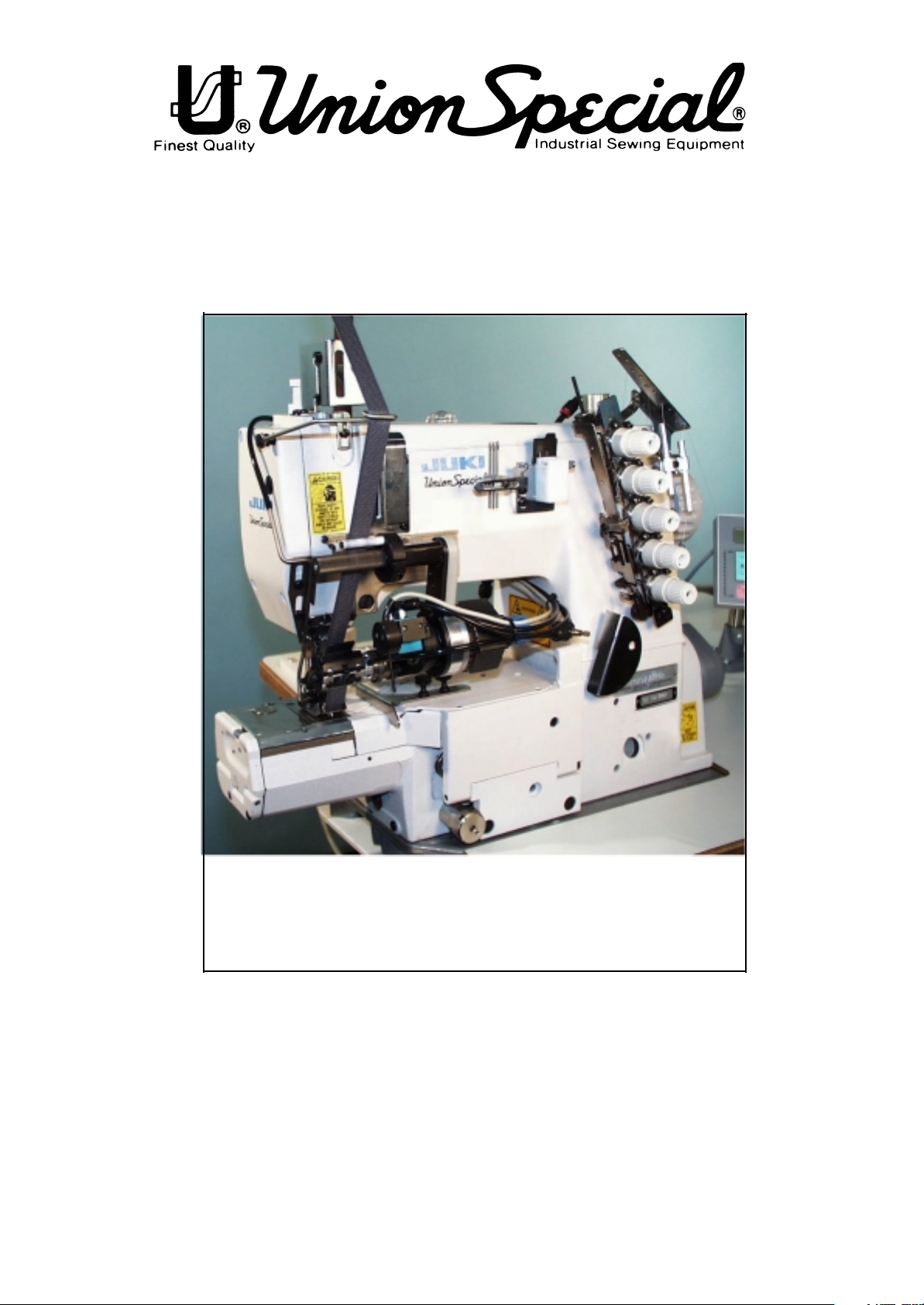
TWO NEEDLE CYLINDER BED DOUBLE LOCKED STITCH
MACHINE FOR ATTACHING CUFF AND HEEL TAPE
ZWEINADEL-ZYLINDER-DOPPELKETTENSTICHMASCHINE ZUM ANNÄHEN VON HOSENSTOSSBAND
CATALOG NO. 307
KATALOG NR. 307
SUPPLEMENT TO CATALOG NO. PT9425
ZUSATZ ZUM KATALOG NR. PT9425
FIRST EDITION
ERSTE AUFLAGE
STYLE / TYP CS112T02-2M111UT
Page 2

First edition / Erste Auflage
© Union Special GmbH
10.2000
2
Page 3

FOR
KLIPP-IT
MOTOR
METERING
THREAD GUIDES
FÜR
KLIPPAB
MOTOR
BANDZUMESSEINRICHUNG
FADENFÜHRUNG
3
Page 4
SAFETY RULES
SICHERHEITSHINWEISE
1. Before putting the machines described in this manual
into service, carefully read the instructions. The starting
of each machine is only permitted after taking notice
of the instructions and by qualified operators.
IMPORTANT! Before putting the machine into service,
also read the safety rules and instructions from the
motor supplier.
2. Observe the national safety rules valid for your country.
3. The sewing machines described in this instruction
manual are prohibited from being put into service
until it has been ascertained that the sewing units
which these sewing machines will be built into, have
conformed with the provisions of EC Machinery
Directive 98/37/EC, Annex II B.
Each machine is only allowed to be used as foreseen.
The foreseen use of the particular machine is
described in paragraph "STYLES OF MACHINES" of this
instruction manual. Another use, going beyond the
description, is not as foreseen.
4. All safety devices must be in position when the
machine is ready for work or in operation. Operation
of the machine without the appertaining safety
devices is prohibited.
5. Wear safety glasses.
1. Lesen Sie vor Inbetriebnahme der in diesem Katalog
beschriebenen Maschinen die Betriebsanleitung
sorgfältig. Jede Maschine darf erst nach Kenntnisnahme der Betriebsanleitung und nur durch
entsprechend unterwiesene Bedienungspersonen
betätigt werden.
WICHTIG: Lesen Sie vor Inbetriebnahme auch die
Sicherheitshinweise und die Betreibsanleitung des
Motorherstellers.
2. Beachten Sie die für Ihr Land geltenden nationalen
Unfallverhütungsvorschriften.
3. Die Inbetriebnahme der in dieser Betriebsanleitung
beschriebenen Nähmaschinen ist solange untersagt,
bis festgestellt wurde daß die Näheinheiten bzw.
Nähanlagen, in die diese Nähmaschinen eingebaut
werden sollen, den Bestimmungen der EG-Richtlinie
Maschinen 98/37/EG, Anhang II B entsprechen.
Jede Maschine darf nur ihrer Bestimmung gemäß
verwendet werden. Der bestimmungsgemäße Gebrauch der einzelnen Maschine ist im Abschnitt
"MASCHINENTYPEN" der Betriebsanleitung beschrieben. Eine andere, darüber hinausgehende
Benutzung ist nicht bestimmungsgemäß.
4. Bei betriebsbereiter oder in Betrieb befindlicher
Maschine müssen alle Schutzeinrichtungen montiert
sein. Ohne zugehörige Schutzeinrichtungen ist der
Betrieb nicht erlaubt.
6. In case of machine conversions and changes all valid
safety rules must be considered. Conversions and
changes are made at your own risk.
7. The warning hints in the instructions are marked
with one of these two symbols.
8. When doing the following the machine has to be
disconnected from the power supply by turning
off the main switch or by pulling out the main plug.
8.1 When threading needle(s), looper,
spreader etc.
8.2 When replacing any parts such as
needle(s), presser foot, throat plate,
looper, spreader, feed dog, needle guard,
folder, fabric guide etc.
8.3 When leaving the workplace and when
the work place is unattended.
8.4 When doing maintenance work.
8.5 When using clutch motors without
actuation lock, wait until motor is stopped
totally.
5. Tragen Sie eine Schutzbrille.
6. Umbauten und Veränderungen der Maschinen dürfen
nur unter Beachtung der gültigen
Sicherheitsvorschriften vorgenommen werden.
Umbauten und Veränderungen erfolgen auf eigene
Verantwortung.
7. Überall da, wo die Betriebsanleitung Warnhinweise
enthält, sind diese durch eines der beiden Symbole
gekennzeichnet.
8. Bei folgendem ist die Maschine durch Ausschalten am
Hauptschalter oder durch Herausziehen des
Netzsteckers vom Netz zu trennen:
8.1 Zum Einfädeln von Nadel(n), Greifer, Leger
usw.
8.2 Zum Auswechseln von Nähwerkzeugen, wie
Nadel, Drückerfuß, Stichplatte, Greifer, Leger,
Transporteur, Nadelanschlag, Apparat, Nähgutführung usw.
8.3 Beim Verlassen des Arbeitsplatzes und bei
unbeaufsichtigtem Arbeitsplatz.
8.4 Für Wartungsarbeiten.
8.5 Bei mechanisch betätigten Kupplungsmo-
toren ohne Betätigungssperre ist der Stillstand
des Motors abzuwarten.
4
Page 5

9. Maintenance, repair and conversion work (see
item 8) must be done only by trained technicians
or special skilled personnel under condsideration
of the instructions.
9. Wartungs-, Reparatur- und Umbauarbeiten (siehe
Punkt 8) dürfen nur von Fachkräften oder entsprechend unterwiesenen Personen unter Beachtung der Betriebsanleitung durchgeführt werden.
Only genuine spare parts approved by UNION
SPECIAL have to be used for repairs.
10. Any work on the electrical equipment must be
done by an electrician or under direction and
supervision of special skilled personnel.
11. Work on parts and equipment under electrical
power is not permitted. Permissible exceptions
are described in the applicable section of standard
sheet EN 50 110 / VDE 0105.
12. Before doing maintenance and repair work on the
pneumatic equipment, the machine has to be
disconnected from the compressed air supply. In
case of existing residual air pressure after
disconnecting from compressed air supply (e.g.
pneumatic equipment with air tank), the pressure
has to be removed by bleeding. Exceptions are
only allowed for adjusting work and function checks
done by special skilled personnel.
Für Reparaturen sind nur die von UNION
SPECIAL freigegebenen Original-Ersatzteile zu
verwenden.
10. Arbeiten an der elekrischen Ausrüstung dürfen nur
von Elektrofachkräften oder unter Leitung und
Aufsicht von entsprechend unterwiesenen Personen durchgeführt werden.
11. Arbeiten an unter Spannung stehenden Teilen und
Einrichtungen sind nicht erlaubt. Ausnahmen regeln
die zutreffenden Teile der EN 50 110 / VDE 0105.
12. Vor Wartungs- und Reparaturarbeiten an pneumatischen Einrichtungen ist die Maschine vom
pneumatischen Versorgungsnetz zu trennen.
Wenn nach der Trennung vom pneumatischen
Versorgungsnetz noch Restenergie ansteht (z. B.
bei pneumatischen Einrichtungen mit Windkessel),
ist diese durch Entlüften abzubauen. Ausnahmen
sind nur bei Einstellarbeiten und Funktionsprüfungen
durch entsprechend unterwiesene Fachkräfte
zulässig.
5
Page 6
6
Page 7
7
Page 8

Parameterliste für Stossband CS112T02-2M111UT mit 997A736
100 200 400 500 600 700 800 900
105 3500 206 II 419 I 568 I 601 I 700 64 800 I 950 10
106 II 221 1200 425 II 602 II 701 I 801 30 951 14
107 I 427 5 603 I 702 37 805 II 952 18
703 161 808 I 953 22
110 5000 605 II 710 60 855 2500 954 26
111 6 606 200 714 350 856 500 956 140
112 0 607 4000 715 110 857 500 957 70
113 II 608 I 716 150 858 5 958 1000
859 7
114 II 609 200 717 150 860 150
116 0 613 I 718 0 861 100
117 400 615 II 719 60 862 100
133 2 616 I 721 40 863 75
134 300 617 II 722 40 864 2550
141 10 618 II 723 20 865 II
867 5
145 20 619 I 729 350 868 200
161 70 620 II 730 300 869 200
189 50 623 10 731 200 870 2500
190 180 633 II 734 10 871 500
191 1500 640 II 783 640 872 500
192 1000 641 150 785 II 873 5
193 260 651 I 789 225 874 0
199 2000 653 II 797 II 875 12
668 I 798 II 876 120
675 II 799 2 877 50
676 I 878 150
879 100
884 13
P 193 Nachlauf Vorabzug Timing Tape Puller 260
P 607 Max. Drehzahl max. speed 4000
P 619 Sicherheitsschalter Ja = I Nein = II Safety switch Yes = I No = II I
P 676 Drehzahl Potentiometer frei speed potentiometer free I
P 714 Einschaltdauer Kettentrenner duty cycle chain-cutter 350
P 715 Einschaltdauer Fadenzieher duty cycle wiper 110
P 719 PFA Einstellung PFA timing 60
P 729 Startverzögerung nach PFA unten delayed start after PFA down 350
P 730 PFA nach oben nach Nahtende PFA up after end of seam 300
P 799 Stoßbandmaschine cuff- and heel tape machine 2
P 805 Drehrichtung Metering direction Metering II
P 808 Drehrichtung Vorabzug / Zackenrad direction Tape Puller / toothed wheel I
P 859 Übersetzung Vorabzug / Zackenrad reduction ratio of main motor stepping 2 7 / 4
P 865 O = Aus Off
I = Zackenschere toothed wheel Off (on)
I I = Vorabzug Tape Puller II (I)
P 875 Übersetzung Stepper 1 (R0 00 dann transmission stepper 1 (R0 00 then sewing
weiternähen bis Band flach näht until tape is evenly attached)
P 950 P 954 Raffwerte shirring factors
8
Page 9
9
Page 10

11.4 List of Parameters (2A_401_2.EN2)
No. Function(Meaning) Level Range of Standard
Values Value
105 (AR/DRZ/STVD) Speed for front B,C 100 - 6400 3500
backtack/stitch condensation
(00000011)
106 (AR/DRZ/STVD) Speed for front B,C 0
backtack/stitch condensation
I variable (treadle-controlled)
II constant (corresponding to <105>)
107 (AR/RIE/DRZ/STVD) Speed for front B,C 0
backtack/stitch condensation when <106> = I
I limited by <105>
II limited by <607>
110 (ER/RIE/DRZ/STVD) Speed for end B,C 100 - 6400 5000
backtack/stitch condensation
111 (LS) Photocell compensation stitches 1 A,B,C 1 - 255 6
(stitches from photocell clear to seam end)
112 (LS) Number of stitches for photocell fade-out A,B,C 0 - 255 0
on knit fabrics (according to stitch size)
113 (LS/START) Start with photocell B,C 0
I when photocell is dark only
II also when photocell is clear
114 (PR/STOP/NE) Stop before seam end after B,C 0
stitch count (last seam section)
I yes
II no
116 (SANL) Soft start stitches A,B,C 0 - 255 0
(00000111)
117 (SANL/DRZ) Speed for soft start stitches B,C 30 - 640 400
133 (PR) Stitches for seam section 6 A,B,C 1 - 255 2
134 (PR) Stitches for seam section 7 A,B,C 0 - 2550 300
141 (FW) Number of stitches until bobbin thread B,C 0 - 255 10
monitor signal becomes active
(signal suppression on bobbin thread monitor)
145 (NE) Number of stitches for seam end A,B,C 0 - 255 15
(00001001)
161 (LS/START) Start delay for start of photocell B,C 0 - 2550 70
189 (VERZ) Delay t1 B,C 0 - 2550 50
190 (VERZ) Delay t2 B,C 0 - 2550 180
191 (VERZ) Delay t3 B,C 0 - 2550 600
192 (VERZ) Delay t4 B,C 0 - 2550 1000
199 (DRZ/LS) Speed for photocell compensation B,C 300 - 6400 2000
stitches
206 (NE/PR/STOP) Interrupt/discontinue seam B,C 0
sections at speed = constant (<203> = II)
I with treadle -2
II with treadle 0
10
Page 11

11.4 Parameterliste (2A_401_2.DE2)
Nr. Funktion(Bedeutung) Ebene Einstell- Standard-
bereich wert
105 (AR/DRZ/STVD) Drehzahl für Anfangsriegel/ B,C 100 - 6400 3500
-stichverdichtung
(00000011)
106 (AR/DRZ/STVD) Drehzahl für Anfangsriegel/ B,C 0
-stichverdichtung
I variabel (pedalabhängig)
II konstant (entspr. <105>)
107 (AR/DRZ/STVD) Drehzahl für Anfangsriegel/ B,C 0
-stichverdichtung bei <106> = I
I begrenzt durch <105>
II begrenzt durch <607>
110 (ER/RIE/DRZ/STVD) Drehzahl für Endriegel/ B,C 100 - 6400 5000
-stichverdichtung
111 (LS) Lichtschrankenausgleichsstiche 1 A,B,C 1 - 255 6
(Stichzahl von Lichtschranke hell bis
Nahtende)
112 (LS) Stichzahl zur Lichtschrankenausblendung A,B,C 0 - 255 0
bei Maschenware(entsprechend der
Maschenweite)
113 (LS/START) Start mit Lichtschranke B,C 0
I nur wenn Lichtschranke dunkel
II auch wenn Lichtschranke hell
114 (PR/STOP/NE) Stopp vor Nahtende nach B,C 0
Stich zählung (letzte Nahtstrecke)
I ja
II nein
116 (SANL) Sanftanlaufstiche (Soft start) A,B,C 0 - 255 0
(00000111)
117 (SANL/DRZ) Drehzahl für Sanftanlaufstiche B,C 30 - 640 400
133 (PR) Stiche für Nahtstrecke 6 A,B,C 1 - 255 2
134 (PR) Stiche für Nahtstrecke 7 A,B,C 0 - 2550 300
141 (FW) Stichzahl bis Spulenfadenwächter-SignalB,C 0 - 255 10
wirksam ist
(Signalunterdrückung des Spulenfadenwächters)
145 (NE) Stichzahl für Nahtende A,B,C 0 - 255 15
(00001001)
161 (LS/START) Startverzögerung für B,C 0 - 2550 70
Lichtschrankenstart
189 (VERZ) Verzögerungszeit t1 B,C 0 - 2550 50
190 (VERZ) Verzögerungszeit t2 B,C 0 - 2550 180
191 (VERZ) Verzögerungszeit t3 B,C 0 - 2550 600
192 (VERZ) Verzögerungszeit t4 B,C 0 - 2550 1000
199 (DRZ/LS) Drehzahl für B,C 300 - 6400 2000
Lichtschrankenausgleichs stiche
206 (NE/PR/STOP) Unterbrechen/Abbrechen B,C 0
der Nahtstrecken bei Drehzahl = konstant (<203> = II)
I mit Pedal -2
II mit Pedal 0
11
Page 12

221 (PR/DB/DRZ) Speed limitation for sewing B,C 300 - 6400 1200
programs (or sewing program 1)
419 (RIV/RIUNT/STVD) Function of external key B,C 0
I backtack/stitch condensation inversion
II backtack/stitch condensation suppression
(flip-flop function)
425 (ENTKET) Unlocking of chain at seam end A,B,C 0
I yes
II no
427 (PF/HV/PULL/STOP/MESSER) Selection of B,C 1 - 5 5
the function available with input E4
1 = presser foot
2 = stroke adjustment
3 = control of puller@4 = stop
5 = chopper
6-9 without function
568 (TUM/STVD/BSN) output A4 is at B,C 0
I Feed reverse / stitch condensation
II Tape cutter
601 (SN) Trimming B,C 0
I yes
II no
602 (NE) Seam end at treadle position B,C 0
I slightly heeled (-1)
II fully heeled (-2)
603 (START) Start after seam end B,C 0
I after treadle 0 only
II immediate start of operation
605 (DRZ) Actual speed in display B,C 0
I yes
II no
606 (DRZ) Speed: level 1 (min.) B,C 30 - 640 200
(00010001)
607 (DRZ) Speed: level 12 (max.) B,C 100 - 10000 4000
608 (DRZ) Speed level curve (treadle B,C 0
characteristic)
I linear
II not linear
609 (SN/DRZ) Trimming speed 1 B,C 30 - 300 200
(00010011)
613 (ANLSP/STOP) Input „Ex“ induces block/stop B,C 0
at
I potential „zero“
II potential „plus“
615 (LS) End recognition when photocell goes B,C 0
I from light to dark
II from dark to light
616 (NPW/NHOS) Function of external key (input B,C 0
E2)
I needle position change-over (NPW)
II needle up without trimming (NHOS)
12
Page 13

221 (PR/DB/DRZ) Drehzahlbegrenzung für Näh- B,C 300 - 6400 1200
programme (bzw. Nähprogramm 1)
419 (RIV/RIUNT/STVD) Funktion des externen B,C 0
Tasters
I Riegelinvertierung/
Stichverdichtungsinvertierung
II Riegelunterdrückung/Stichverdichtungsunterdrückung (Flip-Flop-Funktion)
425 (ENTKET) Entketteln am Nahtende A,B,C 0
I ja
II nein
427 (PF/HV/PULL/STOP/MESSER) Auswahl der B,C 1 - 5 5
Funktion des Eingangs E4
1 = Presserfuß
2 = Hubverstellung
3 = Pullersteuerung
4 = Stopp
5 = Abhacker
6 - 9 z. Z. keine Funktion
568 (TUM/STVD/BSN) Ausgang A5 ist bei B,C 0
I Transportumstellung / Stichverdichtung
II Bandschneider
601 (SN) Schneiden B,C 0
I ja
II nein
602 (NE) Nahtende bei Pedalstellung B,C 0
I leicht rückwärts (-1)
II voll rückwärts (-2)
603 (START) Start nach Nahtende B,C 0
I nur nach Pedal 0
II sofortiger Nähbeginn
605 (DRZ) Istwert in der Anzeige(<725>) B,C 0
I ja
II nein
606 (DRZ) Drehzahl: Stufe 1 (min.) B,C 30 - 640 200
(00010001)
607 (DRZ) Drehzahl: Stufe 12 (max.) B,C 100 - 10000 4000
608 (DRZ) Drehzahlstufenkurve B,C 0
(Pedalcharakteristik)
I linear
II nicht linear
609 (SN/DRZ) Schneiddrehzahl 1 B,C 30 - 300 200
(00010011)
613 (ANLSP/STOP) Eingang“Ex“ führt zu B,C 0
Laufsperre/Stopp
I bei Potential „null“
II bei Potential „plus“
615 (LS) Enderkennung durch Lichtschranke B,C 0
I von hell nach dunkel
II von dunkel nach hell
616 (NPW/NHOS) Funktion des externen Tasters B,C 0
(Eingang E2)
I Nadelpositionswechsel (NPW)
II Nadel hoch ohne Schneiden (NHOS)
13
Page 14

617 (EST/RIV/STVD) Function of external key B,C 0
(input E3)
I single stitch (EST)
II backtack/stitch condensation inverted (RI
V)
618 (RDR) Inverse rotation after seam end B,C 0
I yes
II no
619 (SN/ANLSP/STOP) Control of thread trimming B,C 0
(safety switch no run)
I yes
II no
620 (FW) Thread monitor function B,C 0
I yes
II no
623 (RDR/VERZ) Delay in start-up time (ms) for B,C 0 - 2550 10
inverse rotation
633 (SN/PF) Trimming and presser foot B,C 0
I with treadle „-2“ only (<602> = II)
II corresponding to <602>
640 (LS/START) Start possible by obscuring the B,C 0
photo- cell (if existing, note parameter 113!)
I yes
II no
641 (LS/START/VERZ) Delay before start (ms) B,C 0 - 2550 150
after photocell (at <640> = I)
651 (PF) Presser foot with automatic descent on B,C 0
machine stop
I yes
II no
653 (PEIPO) Target stitch before sewing B,C 0
I yes
II no
668 (BLA/WI) Thread wiper/thread clearer B,C 0
I yes
II no
(00010101)
675 (NAPO) Automatic needle change-over into B,C 0
position@2 (up) after enabling
I yes
II no
676 (DRZ) Speed adjustment via potentiometer B,C 0
possible
I yes
II no
700 (NAPO) Needle position 0 B,C 0 - 239 0
(reference position of the needle)
701 (NAPO) Angular adjustment B,C 0
I with handwheel (teach-in)
II by keys (+/-)
14
Page 15

617 (EST/RIV/STVD) Funktion des externen B,C 0
Tasters (Eingang E3)
I Einzelstich (EST)
II Riegel/Stichverdichtung invertiert (RIV)
618 (RDR) Rückdrehen nach Nahtende B,C 0
I ja
II nein
619 (SN/ANLSP/STOP) Überwachung des B,C 0
Fadenschneiders (Anlaufsperre)
I ja
II nein
620 (FW) Fadenwächterfunktion B,C 0
I ja
II nein
623 (RDR/VERZ) Einschaltverzögerung (ms) für B,C 0 - 2550 10
Rückdrehen
633 (SN/PF) Schneiden und Presserfuß B,C 0
I nur mit Pedal „-2“ (<602> = II)
II entsprechend <602>
640 (LS/START) Start durch Lichtschranke B,C 0
abdunkeln möglich (wenn vorhanden,
Parameter 113 beachten!)
I ja
II nein
641 (LS/START/VERZ) Startverzögerung (ms) B,C 0 - 2550 150
nach Lichtschranke (bei <640> = I)
651 (PF) Presserfuß mit automatischer AbsenkungB,C 0
bei Stillstand der Maschine
I ja
II nein
653 (PEIPO) Peilposition vor dem Nähen B,C 0
I ja
II nein
668 (BLA/WI) Fadenwischer/Fadenausbläser B,C 0
I ja
II nein
(00010101)
675 (NAPO) Nadel automatisch nach Einschalten B,C 0
in Position 2 (oben)
I ja
II nein
676 (DRZ) Drehzahleinstellung über B,C 0
Potentiometer möglich
I ja
II nein
700 (NAPO) Nadelposition 0 B,C 0 - 239 0
(Referenzposition der Nadel)
701 (NAPO) Winkeleinstellungen B,C 0
I am Handrad (teach-in)
II mit Tastern (+/-)
15
Page 16

702 (NAPO) Needle position 1 (needle down) B,C 0 - 239 210
(00010111)
703 (NAPO) Needle position 2 (thread take-up B,C 0 - 239 60
lever up)
710 (NAPO/NHOS) Needle position 3 (needle up) B,C 0 - 239 60
(00011011)
714 (EINZ/SN/RDR) Duration (ms) for chainstitch B,C 0 - 2550 350
trimming or inverse rotation
715 (EINZ/WI) Duration (ms) of thread wiper B,C 0 - 2550 110
716 (VERZ/WI) Delay in start-up time (ms) for B,C 0 - 2550 150
thread wiper
717 (SN/VERZ) Delay in start-up time (ms) for B,C 0 - 2550 150
trimming method when the machine is not
activated by the treadle
718 (STBR) Timing of residual brake B,C 0 - 100 0
(0 = brake off)
719 (PF/TA) Timing output A4 B,C 0 - 100 60
(0 = 100% switching on)
721 (TUM/TA) Timing output A5 B,C 0 - 100 40
(0 = 100% switching on)
722 (DRZAN) Acceleration ramp B,C 1 - 50 40
1 gradual
50 steep
723 (DRZAB) Brake ramp B,C 1 - 50 20
1 gradual
50 steep
729 (STVERZ/PF) Start delay after lowering B,C 0 - 2550 350
presser foot
730 (PF/VERZ) Lift delay for presser foot after B,C 0 - 2550 300
seam end
731 (ER/WRIE/VERZ) Delay before stitch counting B,C 0 - 2550 200
for end backtack (ERV)
734 (SN/TA) Timing output A2 B,C 0 - 90 10
783 (BLA/EINZ) Time needed to switch on (ms) B,C 0 - 2550 640
for thread blower
758 (REG/DRZAB) Deceleration ramp B,C 0
I braking as per <723>
II braking with maximal moment
789 (PEIPO) Needle position 10 B,C 0 - 239 225
(target stitch)
797 (HWT) Hardware test B,C 0
I yes
II no
798 (EBC) Programming level C B,C 0
I yes
II no
16
Page 17

702 (NAPO) Nadelposition 1 (Nadel unten) B,C 0 - 239 210
(00010111)
703 (NAPO) Nadelposition 2 (Fadenhebel oben) B,C 0 - 239 60
710 (NAPO/NHOS) Nadelposition 3 (Nadel oben) B,C 0 - 239 60
(00011011)
714 (EINZ/SN/RDR) Einschaltzeit (ms) für B,C 0 - 2550 350
Kettenstich schneiden oder Rückdrehen
715 (EINZ/WI) Einschaltzeit (ms) für Fadenwischer B,C 0 - 2550 110
716 (VERZ/WI) Einschaltverzögerungszeit (ms) B,C 0 - 2550 150
für Fadenwischer
717 (VERZ/SN) Einschaltverzögerungszeit (ms) B,C 0 - 2550 150
für Schneidsystem in Ruhelage
718 (STBR) Stillstandsbremse-Taktung B,C 0 - 100 0
(0 = Bremse aus)
719 (PF/TA) Taktung Ausgang A4 B,C 0 - 100 60
(0 = 100% Einschaltung)
721 (TUM/TA) Taktung Ausgang A5 B,C 0 - 100 40
(0 = 100% Einschaltung)
722 (DRZAN) Beschleunigungsrampe B,C 1 - 50 40
1 flach
50 steil
723 (DRZAB) Bremsrampe B,C 1 - 50 20
1 flach
50 steil
729 (STVERZ/PF) Startverzögerung nach B,C 0 - 2550 350
Absenkung des Presserfußes
730 (PF/VERZ) Anhebeverzögerung für PresserfußB,C 0 - 2550 300
nach Nahtende
731 (ER/WRIE/VERZ) Stichzählverzögerung für B,C 0 - 2550 200
Endriegel (ERV)
734 (SN/TA) Taktung Ausgang A2 B,C 0 - 90 10
783 (BLA/EINZ) Einschaltzeit (ms) für B,C 0 - 2550 640
Fadenausbläser
758 (REG/DRZAB) Bremsrampe B,C 0
I Bremsen entsprechend <723>
II Bremsen mit maximalem Moment
789 (PEIPO) Nadelposition 10 (Peilposition) B,C 0 - 239 225
797 (HWT) Hardware-Test B,C 0
I ja
II nein
798 (EBC) Programmierebene C B,C 0
I ja
II nein
17
Page 18

799 (MAKL) Machine class which has been B,C 1 - 3 2
selected
(00011101)
800 (DRR) Direction of motor rotation viewed from B,C 0
belt pulley
I left-hand rotation
II right-hand rotation
801 (RDR) Reverse rotation angle after seam B,C 5 - 200 30
end
805 (DRR/ZUSAN/SMOT) Rotational direction of B,C 0
auxiliary drive
I lefthand rotation
II righthand rotation
808 (DRR/ZUSAN/SMOT) Rotating direction of B,C 0
auxiliary drive 2
I lefthand rotation
II righthand rotation
850 (DRZ) Maximum motor speed C 4500
851 (PR/DRZAB) Brake ramp for stitch-count C 0
seams
I steep
II gradual
855 (SMOT) maximum speed of stepping motor 2 B,C 10 - 2550 2500
856 (SMOT) Start-/stopping speed of stepping B,C 10 - 1000 500
motor 2
857 (SMOT) band engagement speed of stepping A,B,C 10 - 1000 100
motor 2
858 (SMOT) acceleration of stepping motor 2 B,C 1 - 20 5
859 (SMOT) reduction ratio of main motor/steppingB,C 1 - 255 20
motor 2
860 (SMOT) acceleration increments of stepping B,C 0 - 255 150
motor 2
861 (SMOT) braking increments of stepping motor B,C 0 - 255 100
2
862 (SMOT) maximum current of stepping motor 2 B,C 1 - 255 255
(255 = 3.6 A)
863 (SMOT) stationary current of stepping motor 2 B,C 0 - 255 128
(255 = 3.6 A)
864 (SMOT/VERZ) delay time from stop until B,C 0 - 2550 2550
switch-on of stationary current of stepping
motor 2 (ms)
865 (SMOT) Stepping motor 2 activated A,B,C 0
I yes
II no
18
Page 19

799 (MAKL) Ausgewählte Maschinenklasse B,C 1 - 3 2
(00011101)
800 (DRR) Motordrehrichtung mit Blick auf B,C 0
Keilriemen- scheibe
I Linkslauf
II Rechtslauf
801 (RDR) Rückdrehwinkel nach Nahtende B,C 5 - 200 30
805 (DRR/ZUSAN/SMOT) Drehrichtung B,C 0
Zusatzantrieb
I Linkslauf
II Rechtslauf
808 (DRR/ZUSAN/SMOT) Drehrichtung B,C 0
Zusatzantrieb 2
I Linkslauf
II Rechtslauf
850 (DRZ) Maximale Motordrehzahl C 4500
851 (PR/DRZAB) Bremsrampe für gezählte Nähte C 0
I steil
II flach
855 (SMOT) Maximaldrehzahl des Schrittmotors 2 B,C 10 - 2550 2500
856 (SMOT) Start-/Stopdrehzahl des Schrittmotors B,C 10 - 1000 500
2
857 (SMOT) Band-Vorlagegeschwindigkeit des A,B,C 10 - 1000 100
Schrittmotors 2
858 (SMOT) Beschleunigung des Schrittmotors 2 B,C 1 - 20 5
859 (SMOT) Untersetzungsverhältniss B,C 1 - 255 20
Hauptmotor/ Schrittmotor 2
860 (SMOT) Beschleunigungsschritte des B,C 0 - 255 150
Schrittmotors 2
861 (SMOT) Bremsschritte des Schrittmotors 2 B,C 0 - 255 100
862 (SMOT) Maximalstrom des Schrittmotors 2 B,C 1 - 255 255
(255 = 3,6A)
863 (SMOT) Stillstandsstrom des Schrittmotors 2 B,C 0 - 255 128
(255 = 3,6A)
864 (SMOT/VERZ) Verzögerungszeit (ms) von B,C 0 - 2550 2550
Stillstand bis Einschaltung
Stillstandsstrom des Schrittmotors 2
865 (SMOT) Schrittmotor 2 aktiv A,B,C 0
I ja
II nein
19
Page 20

867 (REG) integral amplification, band regulation B,C 0 - 40 5
868 (SMOT) band forward movement 2 of A,B,C 0 - 2550 200
stepping motor 1
869 (SMOT) band reverse movement 2 of A,B,C 0 - 2550 200
stepping motor 1
870 (SMOT) maximum speed of stepping motor B,C 10 - 2550 2500
1
871 (SMOT) Start-/stopping speed of stepping B,C 10 - 1000 200
motor 1
872 (SMOT) band engagement speed of stepping A,B,C 10 - 1000 500
motor 1
873 (SMOT) acceleration of stepping motor 1 B,C 1 - 20 5
874 (SMOT/REG) proportional amplification of B,C 0 - 50 0
band tension regulation
875 (SMOT) reduction ratio of main B,C 0 - 255 22
motor/stepping motor 1
876 (SMOT) band forward movement of stepping A,B,C 0 - 2550 200
motor 1
877 (SMOT) band reverse movement 2 of A,B,C 0 - 2550 50
stepping motor 1
878 (SMOT) acceleration increments of stepping B,C 0 - 255 150
motor 1
879 (SMOT) braking increments of stepping motor B,C 0 - 255 100
1
884 (REG) Proportional amplification of the speed B,C 4 - 50 20
control (in general)
885 (REG) Integral amplification of the speed C 0 - 100 30
control
886 (REG) Proportional amplification of the order C 1 - 50 20
controllers
887 (REG) Differential amplification of the order C 1 - 100 30
controllers
889 (EINZ/REG) Time required for order C 0 - 1000 400
controlling (0 = always)
890 (REG) Proportional amplification of the C 1 - 50 25
superior order controllers for the residual
brake
891 (REG) Proportional amplification of the lower C 1 - 50 20
speed controllers for the residual brake
894 (REG) Rotational direction of motor and C 0
synchronizer
I different
II same
20
Page 21

867 (REG) Integralverstärkung B,C 0 - 40 5
Bandspannungsregler
868 (SMOT) Bandtransportstrecke 2 vorwärts A,B,C 0 - 2550 200
des Schrittmotors 1
869 (SMOT) Bandtransportstrecke 2 rückwärts A,B,C 0 - 2550 200
des Schrittmotors 1
870 (SMOT) Maximaldrehzahl des Schrittmotors 1 B,C 10 - 2550 2500
871 (SMOT) Start-/Stopdrehzahl des Schrittmotors B,C 10 - 1000 200
1
872 (SMOT) Band-Vorlagegeschwindigkeit des A,B,C 10 - 1000 500
Schrittmotors 1
873 (SMOT) Beschleunigung des Schrittmotors 1 B,C 1 - 20 5
874 (SMOT/REG) Proportional-Verstärkung B,C 0 - 50 0
Bandspannungsregelung
875 (SMOT) Untersetzungsverhältniss B,C 0 - 255 22
Hauptmotor/ Schrittmotor 1
876 (SMOT) Bandtransportstrecke 1 vorwärts A,B,C 0 - 2550 200
des Schrittmotors 1
877 (SMOT) Bandtransportstrecke 1 rückwärts A,B,C 0 - 2550 50
des Schrittmotors 1
878 (SMOT) Beschleunigungsschritte B,C 0 - 255 150
des Schrittmotors 1
879 (SMOT) Bremsschritte des Schrittmotors 1 B,C 0 - 255 100
884 (REG) Proportional-Verstärkung der B,C 4 - 50 20
Drehzahl- regelung (allgemein)
885 (REG) Integral-Verstärkung der C 0 - 100 30
Drehzahlregelung
886 (REG) Proportional-Verstärkung des C 1 - 50 20
Lagereglers
887 (REG) Differential-Verstärkung des C 1 - 100 30
Lagereglers
889 (EINZ/REG) Zeit für Lageregelung C 0 - 1000 400
(0 = immer)
890 (REG) Proportional-Verstärkung des C 1 - 50 25
übergeordneten Lagereglers für
Stillstandsbremse
891 (REG) Proportional-Verstärkung des C 1 - 50 20
untergeordneten Drehzahlreglers für
Stillstandsbremse
894 (REG) Laufrichtung von Motor und C 0
Istwertgeber
I verschieden
II gleich
21
Page 22

897 (SONST) Commutation transmitter C 0
I ABB
II QR
898 (SONST) Number of motor poles C 0
I 4 poles
II 6 poles
950 (SMOT/RAFF) gathering value 1 of stepping A,B,C 0 - 200 10
motor axis 1
951 (SMOT/RAFF) gathering value 2 of stepping A,B,C 0 - 200 14
motor axis 1
952 (SMOT/RAFF) gathering value 3 of stepping A,B,C 0 - 200 18
motor axis 1
953 (SMOT/RAFF) gathering value 4 of stepping A,B,C 0 - 200 22
motor axis 1
954 (SMOT/RAFF) gathering value 5 of stepping A,B,C 0 - 200 26
motor axis 1
956 (SMOT) maximum current of stepping motor 1 B,C 1 - 255 140
(255 = 3.6 A)
957 (SMOT) stationary current of stepping motor B,C 0 - 255 70
1 (255 = 3.6 A)
958 (SMOT/VERZ) delay time from stop until B,C 0 - 2550 1000
switch-on of stationary current of stepping
motor 1 (ms)
990 (REG) Distance to position at switch over C 1 - 255 32
from speed control to position control
22
Page 23

897 (SONST) Kommutierungsgeber C 0
I ABB
II QR
898 (SONST) Polzahl des Motors C 0
I 4 Pole
II 6 Pole
950 (RAFF/SMOT) Raffwert 1 der A,B,C 0 - 200 10
Schrittmotorachse 1
951 (RAFF/SMOT) Raffwert 2 der A,B,C 0 - 200 14
Schrittmotorachse 1
952 (RAFF/SMOT) Raffwert 3 der A,B,C 0 - 200 18
Schrittmotorachse 1
953 (RAFF/SMOT) Raffwert 4 der A,B,C 0 - 200 22
Schrittmotorachse 1
954 (RAFF/SMOT) Raffwert 5 der A,B,C 0 - 200 26
Schrittmotorachse 1
956 (SMOT) Maximalstrom des Schrittmotors 1 B,C 1 - 255 140
(255 = 3,6A)
957 (SMOT) Stillstandsstrom des Schrittmotors 1 B,C 0 - 255 70
(255 = 3,6A)
958 (SMOT/VERZ) Verzögerungszeit (ms) von B,C 0 - 2550 1000
Stillstand bis Einschaltung
Stillstandsstrom des Schrittmotors 1
990 (REG) Entfernung von Sollposition bei C 1 - 255 32
Umschaltung von Drehzahl- auf Lageregelung
23
Page 24

24
Page 25

25
Page 26

Stossbandmaschine
C:‘----KCA‘buschpneu.vsd
998-82E
998-82EA
Stecker X 4
26
999 - 165
999 - 196
999 - 411 G1/8 - 4
999 - 411 G1/8 - 6
999 - 196
999 - 411 G 1/8 - 4
zum Klippab / to Klipp - it
999 - 151
999 - 153 A
B
B
B
B
B
B
CS 112 T 02 - 2 M 111 / UT
WS72800 GHP 1 A
999- 460 G1/8 - 4
A
A
A
A
AB
A
A
671-103 A
A4
A6
A9
A1
A3
A3
A6
999-196 F
Drückerfuss
V1
Presserfoot
Nadelkühlung
V2
Needlecooler
Bandschere
V3
Tape cutter
Klippab
V4
Klipp - it
Fadenbläser
V5
Thread blower
Ausbläser
V6
Blower
Absaugung
V8
Suction
671-104 A
+ 24 V
+ 24 V
+ 24 V
+ 24 V
+ 24 V
+ 24 V
+ 24 V
998-82EB
998-82E1-10
1
2
3
4
5
6
7
8
9
10
1
1
12
998-82EC
90233LE178
Grün 3
Gelb 3
Weiss 2
Weiss 2
grau 6
Gelb 5
+ 24 V Braun 1
+24V Braun 1
Stecker X 6
Filterdruckminderer
Filter Regulator
999 - 411 G 1/8 - 4
zur Nadelkühlung / Fadenbläser
to Needle cooler / Thread wiper
AUF MONTAGEPLATTE
A 10361 BA MONTIERT
999 - 287
999- 411G1/4-
999-140 C
Luftnetz
Air supply
999-401G1/8-6
6
999-179
999-196
Page 27

27
Page 28

28
Page 29

DESCRIPTION OF PARTS
TEILEBESCHREIBUNG
29
Page 30

30
Page 31

313233
Page 32

Page 33

Page 34

Hints for adjusting the thread chain cutter of this sewing machine
Problems with uneven beginning of the thread
34600KCA/ CS112T02-2M111UT
(also see Adjusting Instruction in Catalog 282CA, Page 20 to 25)
1. Make sure that the catching knife - support M (page 40) neither in its right nor in its
left final position hits against the screw (page 40).
In both positions 1 mm of the radius at the end of the guiding slot N (page 38) has
to be visible next to the head of the screw S (page 40) (see also catalog 282CA,
page 22, Fig. 36).
The distance in resting position of the knife carrier M (page 40) can be adjusted
by turning the bolt B (page 40) on the thread of the driving collar L (page 40) as
described above to at least 1 mm. Movement to the left can be limited with the
set collar K (page 36) with the same distance. Tighten screw in set collar K securely.
2. Make sure enough thread is pulled to ensure clean cutting and clamping of the
sewing thread. For this you make a seam, cut off the air and put the needle bar
in its highest position (upper dead center).
Swing in the catching knife completely by pushing against the clevis C (page 36)
of the air cylinder.
Release the clevis again slowly and watch the thread in the area of the take up
hooks H1 to H4 (page 38). Excess thread built up while turning in the catching knife
should be just used up when the catching knife reaches its resting position.
In no way at the end of the movement - in which you have to pull at the clevis C
(page 36) - thread should be pulled from the bobbin through the thread tension.
Is this the case, check the position of the take up hooks H1 to H4. (page 38).
These must be positioned in such a way, that the belonging thread runs closely
underneath without being diverted.
To get more thread increase the movement of the bar 21 (page 38) for the take up
hook H1 to H4 (page 38) by loosening the screw 19 (page 36) and moving it in
small steps upwards until desired thread length is available. Fasten the screws
securely again. Check at the same time if take up hooks H1 to H4 do not hit against
anything or block in some way. Make sure that between take up hooks H2 and
the lower fastening clip of the thread guide strip always a distance of 1 mm remains
when catching knife is turned in - meaning being in its outermost left position.
3. Regulate the speed of the air cylinder with the flow control D (page 36) in such a
way that the speed of the back stroke of the catchingknife is only half the speed
of the forward motion.
4. Please watch for small, approx. 10 mm long u-shaped thread residue inside of the
machine. This is a clue that one or both of the catching knifes cut off the needle
thread loop instead of just cutting it open.
Adjust the knife in the middle of the looper as described in catalog 282CA (S. 22,
Fig. 35).
34
Page 35

3536373839
Page 36

Page 37

Page 38

Page 39

THREAD TENSION
FADENSPANNUNG
Ref. No.
Pos. Nr.
1
2
3
4
5
6
7
8
9
10
11
12
13
14
15
16
17
18
19
20
21
22
23
24
25
26
27
28
29
30
31
32
33
34
35
36
37
38
Part No.
Teil Nr.
29477NL
NS6110420SP
57865
SS7090520SP
50392AP
SS7090520SP
50392AV
59392X
50392AR
57892K
56392G
B3120352000
B3126012000
B3120704000
56392H
B3103804000
B3101804000
B3021804010
B3112704000
56392M
56392L
56392S
SS4120615SP
96711
50932AS
G51358KE
28C
A9858
77A
99296
50392AN
22735
99620
22596
G51346KA
22757
77A
A9858C
99306
A10476B
A10476A
90
Description Beschreibung
Five Thread Tension Assembly
Nut
Lead-in Thread Guide
Screw
Thread Guide
Screw
Guide for tension disc separator
Tension Bracket
Tension Disc Separator
Thread Tension Eyelet
Tension Post
Tension Disc Felt
Tension Disc
Tension Disc Felt
Spring Shield
Spring for spreader (blue)
Spring for needle (red)
Spring for looper (plain)
Ferrule for tension spring
Knob for spreader (blue)
Knob for needle (red)
Knob for looper (plain)
Screw
Spring
Rod for thread puller
Thread Pull-off Hook
Screw
Thread Pull-off Hook
Screw
Shoulder Screw
Tension Release Assembly
Shoulder Screw
Tension Release Assembly
Screw
Tensions Release Eccentric
Screw
Screw
Thread Pull-off
Screw
Thread Guide Support
Thread Guide
Screw
Fünf Fadenspannung komplett
Mutter
Fadenführung
Schraube
Fadenführung
Schraube
Träger für Fadenspannung
Ablöseleiste
Fadenführung
Fadenspannungsbolzen
Filzscheibe für Fadenspannung
Fadenspannungsscheibe
Filzscheibe für Fadenspannung
Federhülse
Feder für Fadenspannung (blau)
Feder für Nadel (rot)
Feder für Greifer (einfach)
Zahnscheibe für Fadenspannung
Fadenspannungsmutter (blau)
Fadenspannungsmutter (rot)
Schraube
Feder
Stange für Fadenspannungsauslösung
Fadenabzug
Schraube
Fadenabzug
Schraube
Zylinderschraube
Auslösestange komplett
Zylinderschraube
Schraube
Exzenterring
Schraube
Schraube
Doppelfadenabzug
Gewindestift
Halter für Fadenführung
Fadenführung
Zylinderschraube
Amt. Req.
Anzahl
1
5
5
2
1
2
2
1
1
5
5
5
10
5
5
1
3
1
5
1
3
1
2
1
1
4
4
1
1
1
1
1
1
1
1
1
2
1
1
1
1
1
Page 40

404142
Page 41

Page 42

Thread Guides Fadenführungen
Part No.
Teil Nr.
A10476D Thread Pull-Off Fadenabzug
A19838 Thread Guide Holder Halter für Fadenführung
A10476CV Thread Guide Fadenführung, vorn
A19827 Rocker Sc hwinghebel
A10476F Thread Pull-Off Fadenabzug
A10476E Thread Pull-Off Fadenabzug
A10476CH Thread Guide Fadenführung, hinten
Description Be schreibung
Page 43

Thread Guides Fadenführungen
Part No.
Teil Nr.
Description Be schreibung
A10476B Thread Guide Support Halter f ür Fadenführ ung
A10476A Thread Guide Fadenführung
A9858C Thread Pull-Off Doppelfadenabzug
43
Page 44

44
Page 45

METERING DEVICE
BANDZUMESSEINRICHTUNG
45
Page 46

46
Page 47

METERING DEVICE
BANDZUMESSEINRICHUNG
47
Page 48

48
Page 49

KNIFE HOLDER ASSEMBLY
MESSERHALTER KOMPLETT
49
Page 50

50
Page 51

51
Page 52

WORLDWIDE SALES AND SERVICE
WELTWEITER VERKAUF UND KUNDENDIENST
Union Special maintains sales and service facilities throughout the
world. These offices will aid you in the selection of the right sewing
equipment for your particular operation. Union Special
representatives and service technicians are factory trained and
are able to serve your needs promptly and efficiently. Whatever
your location, there is a qualified representative to serve you.
Corporate
Office:
Union Special Corporation
One Union Special Plaza
Huntley, IL 60142
Phone: US: 800-344 9698
Phone: 847-669 4200
Fax: 847-669 4258
www.unionspecial.com
Brussels, Belgium
Hong Kong, China
Huntley, IL
Lainate-Milano, Italy
Leicester, England
Lesquin cedex, France
Mexico City, Mexico
Möglingen, Germany
Montreal, Quebec
Singapore
Tokyo, Japan
European Distribution Center:
Union Special unterhält Verkaufs- und KundendienstNiederlassungen in der ganzen Welt. Diese helfen Ihnen in der
Auswahl der richtigen Machine für Ihren speziellen Bedarf. Union
Special Vertreter und Kundendiensttechniker sind in unseren
Werken ausgebildet worden, um Sie schnell und fachmännisch zu
bedienen.
Union Special GmbH
Raiffeisenstrasse 3
D-71696 Möglingen, Germany
Tel.: 49 (0)7141/247-0
Fax: 49 (0)7141/247-100
www.unionspecial.de
Other Representatives throughout all parts of the world.
Weitere Vertretungen in allen
Teilen der Welt.
 Loading...