

Page 1

BK-7
INSTRUCTION MANUAL
Page 2

CONTENTS
Component parts list ......................................................................................................1
1. Installing the main body of automatic bobbin changer ...........................................2
1-1. Attaching the plate cover ...............................................................................................2
1-2. Installing the main body of automatic bobbin changer .............................................. 4
2. Wiring procedure ........................................................................................................5
(1) Wiring to the main body of BK-7 ...............................................................................5
(2) Wiring to the PS-700 ..................................................................................................5
3. Adjusting the installation ...........................................................................................8
3-1. Adjusting the installation of the automatic bobbin changer ......................................8
4. Explanation of operation of the control box of automatic bobbin changer ........15
5. Parts list for the BK-7 ...............................................................................................21
i
Page 3
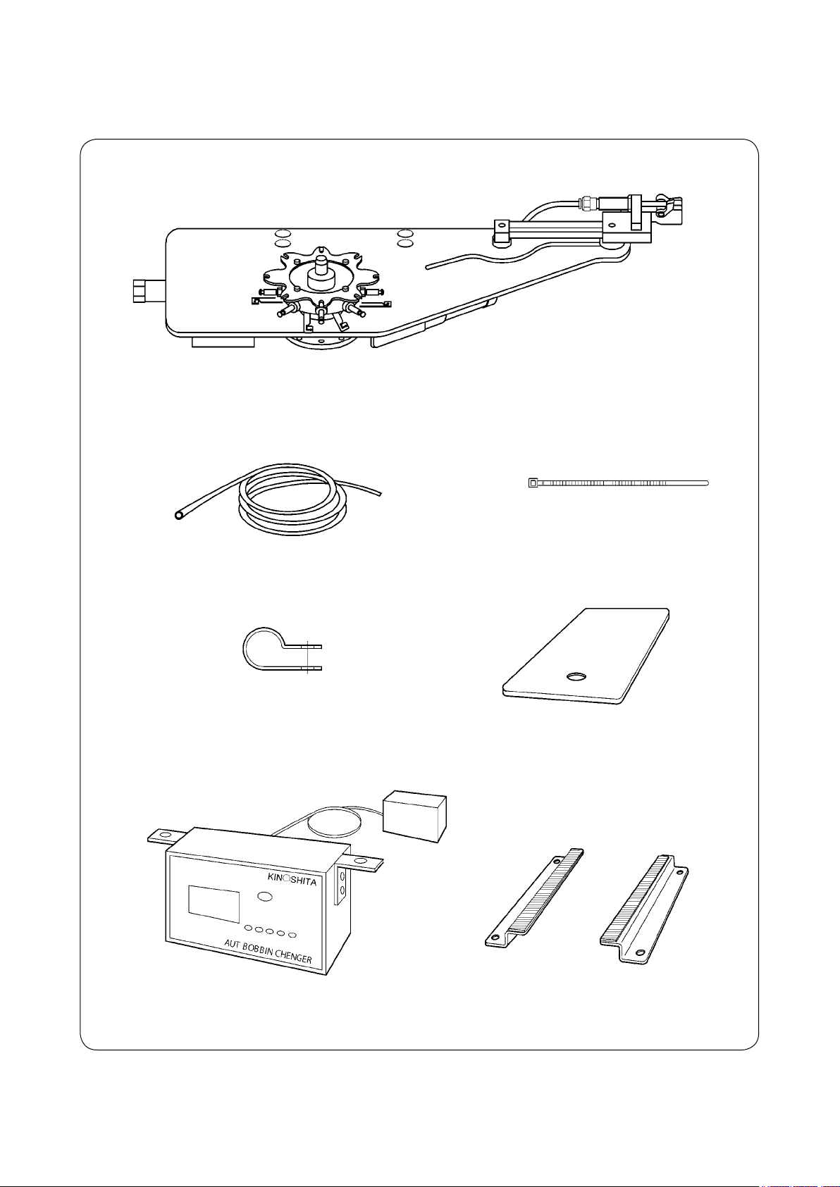
Component parts list
Check the below-stated parts.
Automatic bobbin changer asm., complete set
Setscrew, screw M6 × 20 L, 4 pieces
Cable clip band T-18R, 7 piecesAir hose ø8 × 800 mm
Cable clip SL-9N, 3 pieces
Control box, complete set
Setscrew, screw M5 × 20L, nut M5,
2 pieces each
Opening / closing door set, plate cover
Support plate
Setscrew, screw M4 × 16L, nut M4,
4 pieces each
– 1 –
Page 4
1. Installing the main body of automatic bobbin changer
WARNING :
1. Installation procedure of the automatic bobbin changer must be carried out by a trained technical
expert.
2. Request your distributor or a specialized electrician to carry out electric wiring.
3. Do not connect the power plug of the sewing machine before completing the installation
procedure.
If the start button is pressed during the work by mistake, the sewing machine will actuate, posing a
great risk.
4. Be sure to connect the ground wire.
If the ground wire connection is not proper, electric shock can be caused.
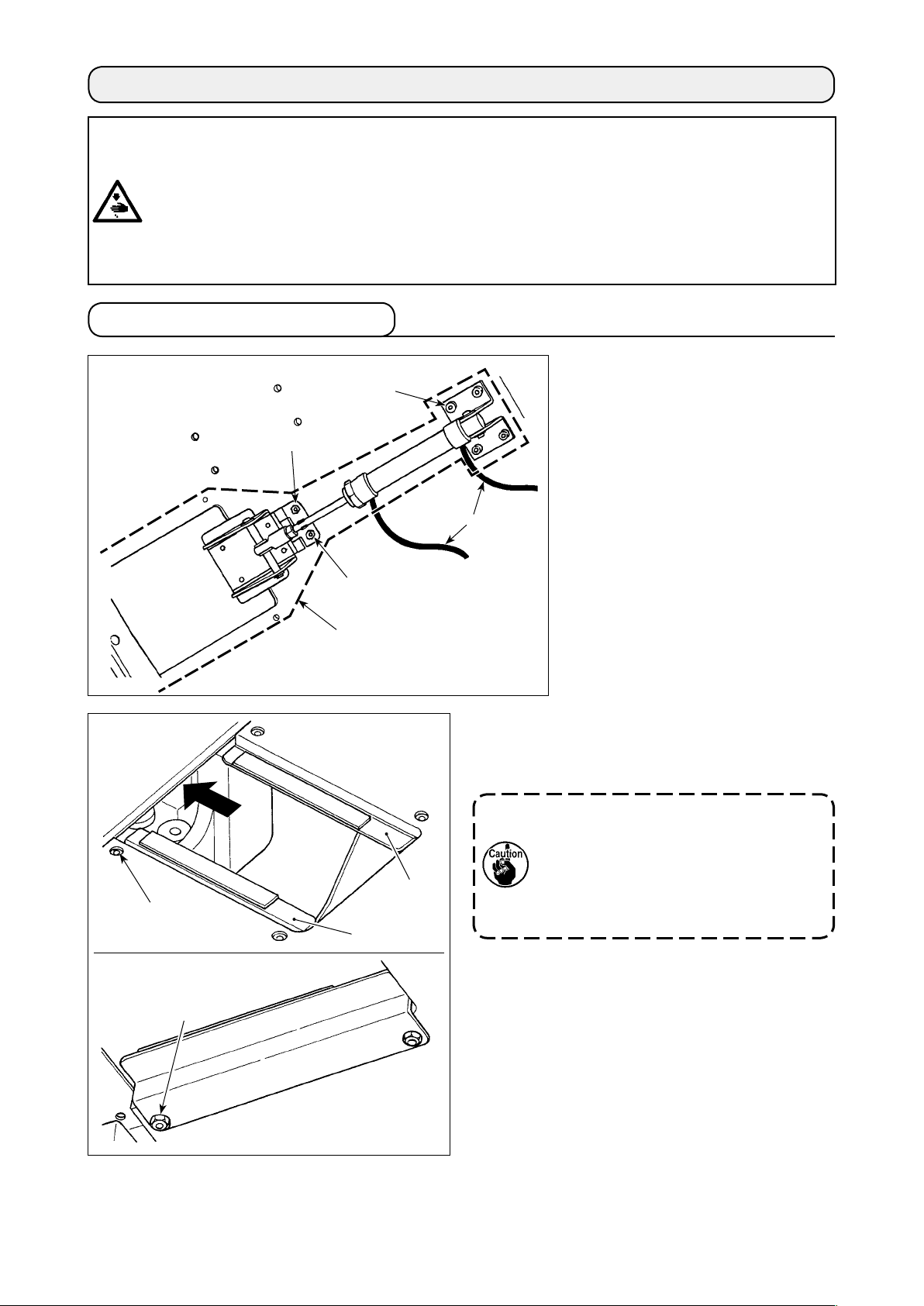
1-1. Attaching the plate cover
1) Pull out two air hoses ❾ from the
❶
❸
❾
manual valve.
Remove screws ❶ (four pieces)
and ❷ (two pieces) and nuts ❸
(two pieces). Detach the opening /
closing table cover asm.
Throat plate
❻
❼
❷
Opening /
closing table
Cover asm.
❺
❹
2) Attach support plates ❹ and ❺ with a table. Se-
cure them with screws ❻ (four pieces) and nuts
(four pieces).
❼
Support plates ❹ and ❺ are provided
with a magnet sheet on their top
surfaces. Attach the support plates with
their magnet-attached sides up and with
their sides with shorter base metal faced
toward the throat plate.
– 2 –
Page 5
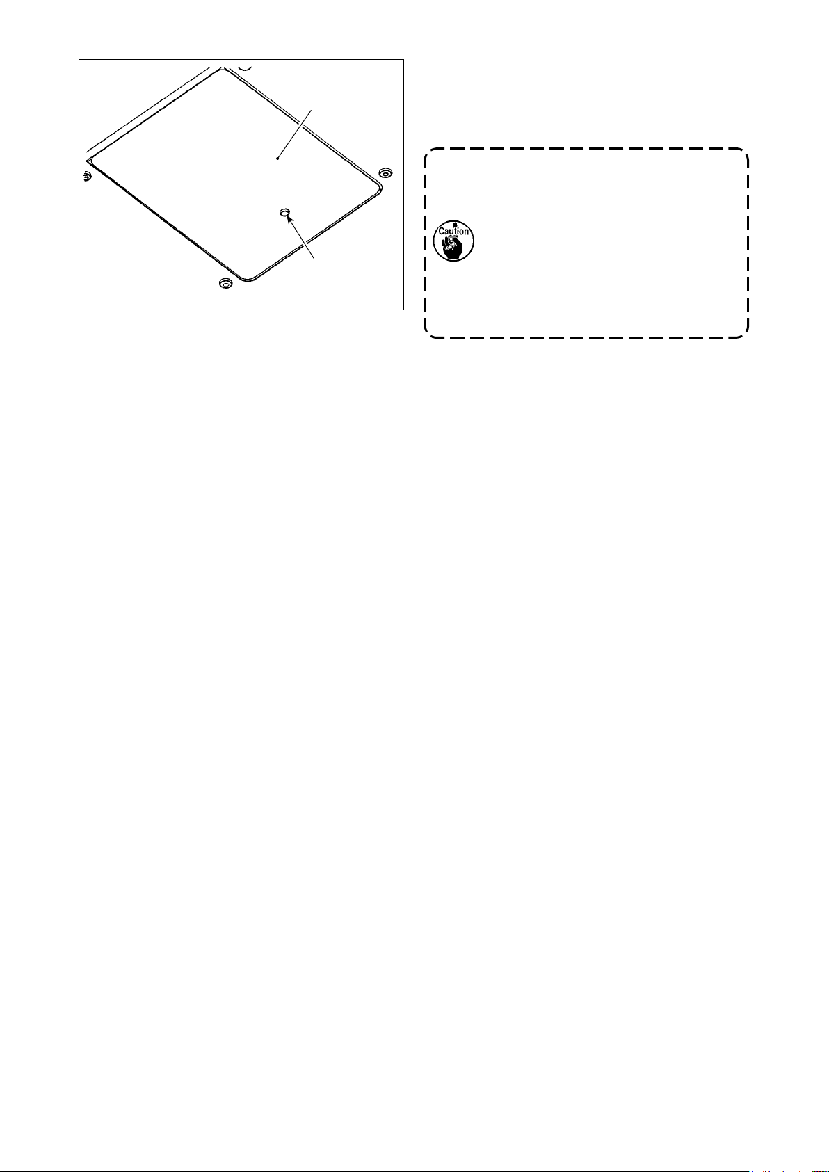
Throat plate
❽
A
3) Fit plate cover ❽ on the table.
Place it in such a way that hole portion A of the
opening / closing cover is brought to opposite side
of the throat plate.
1. Check to make sure that plate cover
does not project the table surface.
❽
If it projects the table surface, correct
by slightly bending part ❹ or ❺.
2. Afterttingplatecover❽ on the
table, carefully adjust the longitudinal
position of the cover so that it does
not come in contact with the throat
plate of sewing machine.
[How to open the plate cover]
Inserting a thin screw driver into hole portion A of
the opening / closing cover, open plate cover ❽.
– 3 –
Page 6
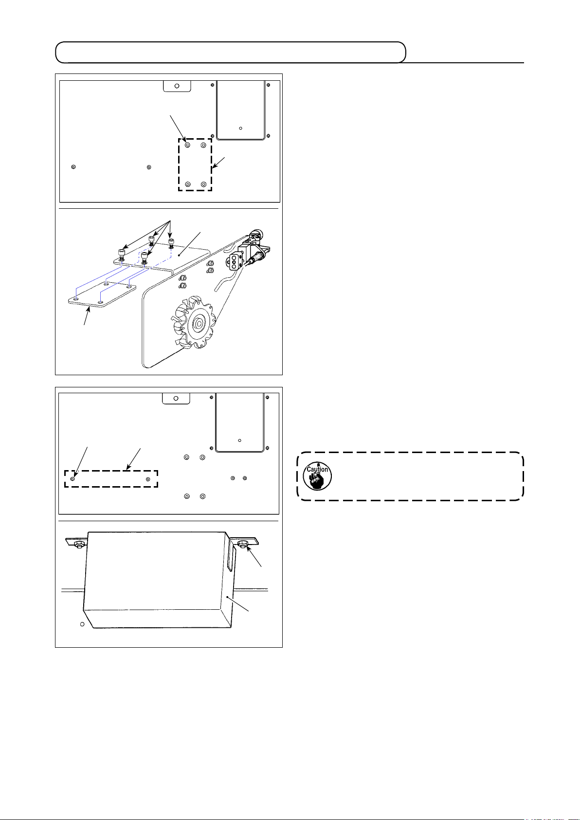
1-2. Installing the main body of automatic bobbin changer
1) Put screws ❶ (four pieces) into the top surface of
table. Fitting bobbin changer mounting plate ❷ on
❶
Location
of screws
which are to
be left in the
current state
❶
❷
❸
those screws, temporarily tighten the screws.
2) Adjust the nal position of the bobbin changer
following the steps of procedure for adjusting the
mounting position of bobbin changer. Then, tight-
en screws ❶ (four pieces) and screw plate ❸.
Location of screws
which are to be left in
the current state
❹
❺
❻
3) Put screws ❹ (two pieces) into the tapped holes
from the top surface of table. Hanging control box
of the bobbin changer on the screws, tighten
❺
nuts ❻ (two pieces).
Attach the control box in such a way that
its operation button faces to the operator
side.
– 4 –
Page 7
2. Wiring procedure
(1) Wiring to the main body of BK-7
②
(2) Wiring to the PS-700
②
①
③
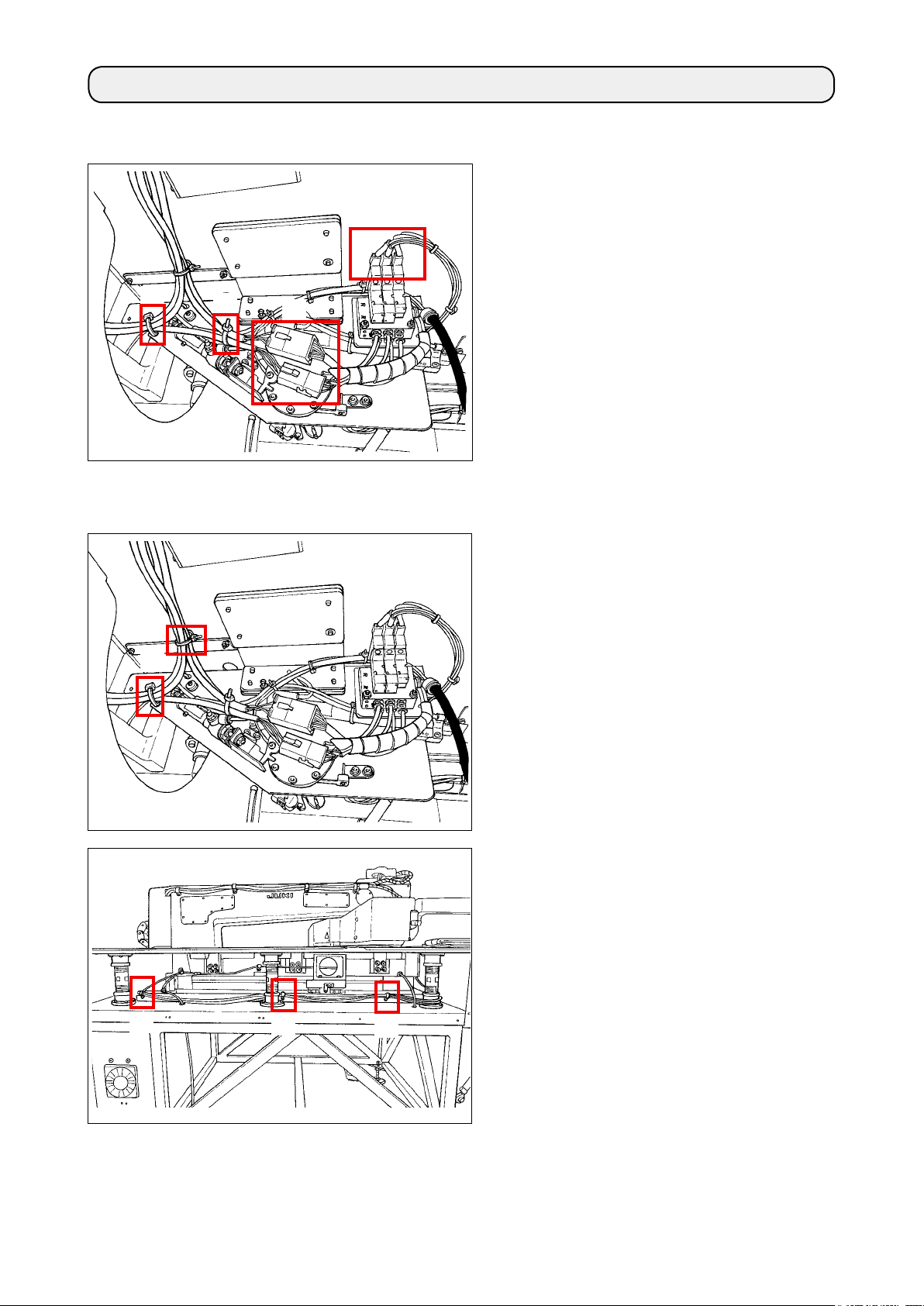
Connect the two wirings coming from the main
①
body of BK-7 and two wirings coming from the
controller while matching their connector num-
bers.
Secure the wirings at two locations with cable
②
clip bands as illustrated in the gure. At this
time, take care not to x the cores.
Connect the cords to the connectors in the
③
order or white one, red one and blue one from
the left as illustrated in the gure.
①
Secure the wirings at two locations as illustrat-
①
ed in the gure. At this time, take care not to
x the cores.
Detach the side cover.
②
Remove cable clamps which secure the Y-ori-
③
gin sensor wirings at three locations. They are
to be changed with the cable clamps supplied
with the unit in the below-stated Step ⑤.
③
③
③
– 5 –
Page 8
⑤
④
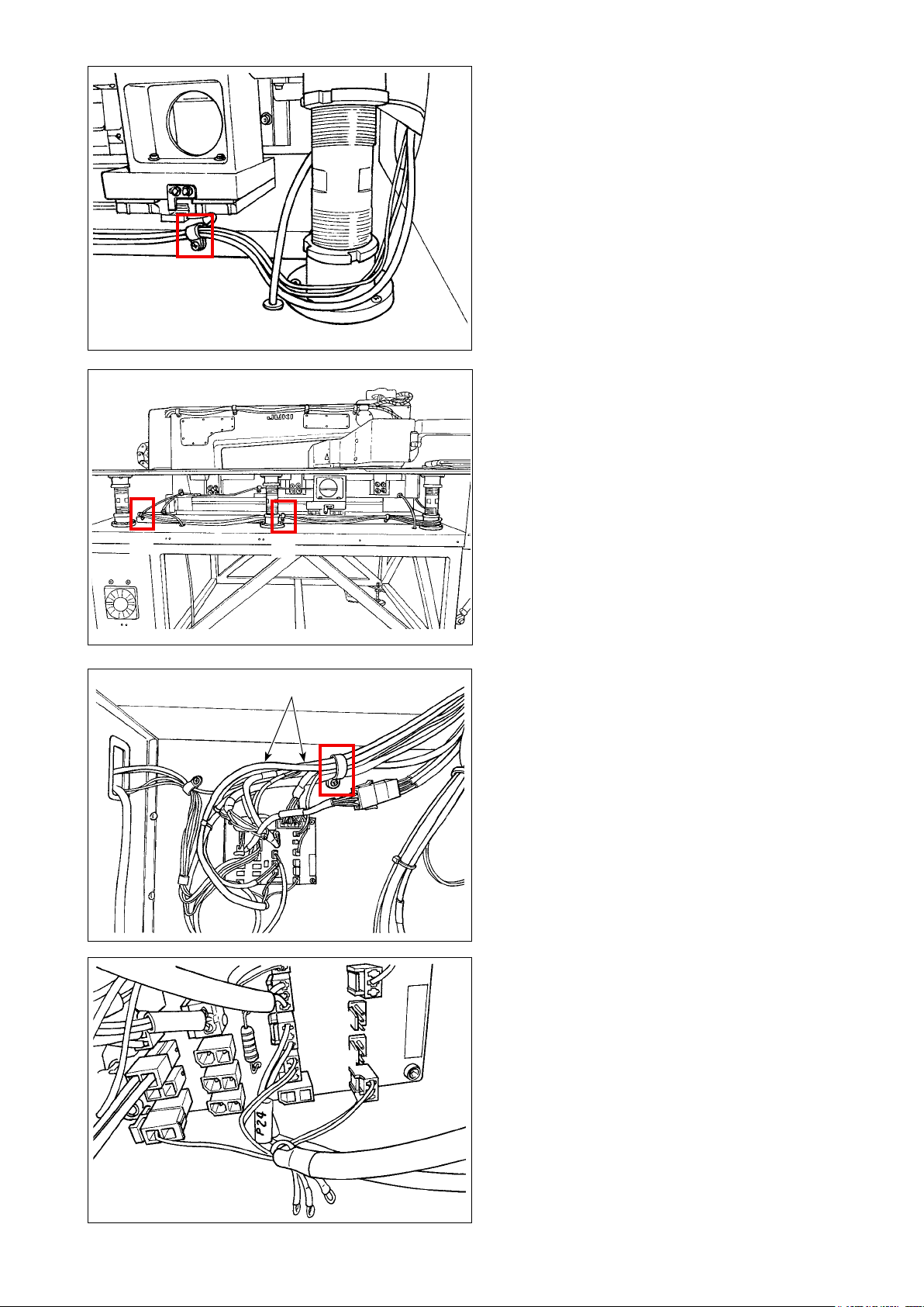
For wiring of cables, pass the two cables
④
coming from the controller along the outside of
strut (this is the wiring route).
Secure the Y origin sensor wirings together
⑤
with the aforementioned two cables and air
tube using the cable clamp supplied with the
unit.
At this time, take care not to bend the wirings
located at the root of Y origin sensor.
Secure the aforementioned three cables, air
⑥
tube and Y origin sensor wirings with cable
clamps supplied with the unit at two locations
as illustrated in the gure.
⑥
⑥
⑦
⑧
Open the storage door on the rear side of the
⑦
main body of PS-700. Draw the cables, wirings
and air tube through the hole into the sewing
machine table.
Pass two wirings through the cable clamps
⑧
which have already been attached to secure
them.
Connect the wirings to the connectors at four
⑨
locations on the PCB.
CZ1324
CZ1316
CZ1320
CZ1327
– 6 –
Page 9

⑩
⑫
After the completion of connection of wirings
⑩
to the PCB, secure the wirings with cable clip
bands.
Close the storage door. Attach the side cover.
⑪
Also detach the air tube which has been con-
⑫
nected to the manual valve.
⑭
Connect the air tube that is wired from BK-7, to the Y union as illustrated in the gure.
⑬
After you have connected the air tube, cut off the original cable tie. Secure the piping with a new cable tie.
⑭
– 7 –
⑬
Page 10

3. Adjusting the installation
3-1. Adjusting the installation of the automatic bobbin changer
WARNING :
1. Adjustment procedure has to be carried out by a trained technical expert.
2. Be sure to turn OFF the power to the sewing machine and to the automatic bobbin changer, and
unplug them. Turn OFF the air supply to decrease the air pressure to "0 (zero)".
It is quite dangerous to actuate the sewing machine and / or the bobbin changer during the
adjustment work.
How to check the installation position of the automatic bobbin changer
■
1. The illustration shown below rep-
resents the state that the opera-
tor grasps the bobbin arm ⑬ and
presses bobbin case ① against
sewing machine hook ⑫ with the
air supply turned ON.
Turn ON the
air supply.
Chuck cylinder
⑪
Clearance
Hook of the
⑫
sewing
machine
Claw opening/
④
closing lever
Bobbin case
①
3. Dimension of clearance provided when chuck claw ③
grasps bobbin case ① and presses it against sewing
machine hook ⑫.
2. Put bobbin ② in the bobbin case. Push claw
opening / closing lever ④ until the bobbin case is
pressed against the sewing machine hook ⑫. In
this state, measure the clearance.
0.3 to 0.5mm
Bobbin arm
Arm head
⑩
⑬
Chuck claw
③
Bobbin
②
Clearance
Press against
the hook
Clearance: 0.3 to 0.5 mm
(in the state the bobbin case is pressed
against the hook)
– 8 –
Page 11

How to adjust the installation position
■
With respect to the X direction, loosen main body anchor bolts ⑨ (four pieces) of the automatic bobbin
・
changer mounting bracket ⑤. Move bobbin changer mounting bracket ⑤ to the right and left to adjust the
installation position of the bobbin changer.
With respect to the Y direction, loosen base tightening bolts ⑥ (four pieces) of bobbin changer base plate
・
. Move base plate ⑦ back and forth to adjust the installation position of the bobbin changer.
⑦
With respect to the Z direction, loosen base tightening bolts ⑥ (four pieces) of bobbin changer base plate
・
. Move base plate ⑦ up and down to adjust the installation position of the bobbin changer.
⑦
If the aforementioned clearance is too small, bobbin case ① and sewing machine hook ⑫
can be broken when arm head ⑩ moves toward the hook side. On the other hand, if the
aforementioned clearance is too large, chuck claw ③ can fail to grasp the bobbin case, causing
a chuck error.
Base tightening bolt
+X
⑥
Base plate
⑦
Sewing
⑫
-Y
machine hook
+Y
Main body
⑨
mounting bolt
Mounting bracket
⑤
Screw plate
⑧
-X
Screw plate
⑮
Bobbin case
①
Bobbin
②
Chuck claw
③
Claw opening / closing lever
④
Mounting bracket
⑤
Base tightening bolt
⑥
Base plate
⑦
+Z
-Z
Screw plate
⑧
Main body mounting bolt
⑨
Arm head
⑩
Chuck cylinder
⑪
Sewing machine hook
⑫
Bobbin arm
⑬
Bobbin cassette
⑭
Screw plate
⑮
Bobbin cassette
⑭
Arm head
⑩
– 9 –
Page 12

Detailed procedure of installation and adjustment
★ ⑧⑨⑩⑪の上下のランプは〈自動モード〉の場合でも、ボビンチェンジャー各部の
動作に従って自動的に順次点灯します。
○○○○○○
⑦ ⑧ ⑨ ⑩ ⑪
4、オートボビンチェンジャーコントロールBOX操作説明
○
■
1) Install the automatic bobbin changer to the sewing machine with M6 cap bolt No. 79 and mounting plate
No. 77.
2) Install the control box to the predened location.
3) Connect and wire the cables and connect the air hose referring to
4) Turn ON the power and air supply. Check to make sure that the lamps mounted on the control box light up
as described below.
Lamps to be checked whether they light up
Power lamp; ❸ Automatic mode lamp; ❹ Bobbin replacement lamp; ❺ Bobbin presence lamp
❸ ❹ ❺
⑫ ③ ④ ⑤
"2. Wiring procedure" p.5
.
㻼㻻㼃㻱㻾
○
Manual mode lamp
⑬ 手動モード時ランプ
㻻㻺
❷
②
㻌㻭㼁㼀㻻㻌㻌 㻌㻌㻮㻻㻮㻮㻵㻺
㻌㻹㻻㻰㻱㻌㻌 㻌㻌㻯㻴㻭㻺㻳㻱
○○○
㻮㻻㻮㻮㻵㻺
㻯㻭㻿㻿㻱㼀㼀㻱㻌
㻌㻯㻴㻭㻺㻳㻱
㼀㻾㻻㼁㻮㻸㻱
○
⑥
⑧⑨⑩⑪各キーの
○ ① ② ③ ④ ⑤
MANUAL ○ ○ ○ ○ ○
㻻㻲㻲
㻌㻭㼁㼀㻻㻌㻮㻻㻮㻮㻵㻺㻌㻯㻴㻭㻺㻳㻱㻾
❶
①
Power switch
❶
Cassette replacement key
❷
Automatic mode lamp
❸
Bobbin replacement lamp
❹
Bobbin presence lamp
❺
Fault lamp
❻
Manual mode key
❼
Chuck opening / closing key
❽
Cassette feed key
❾
Arm head key
Power lamp
Manual mode lamp
❼ ❽ ❾
❽❾
⑧⑨⑩⑪
Backward travel lamp
各キーの後退ランプ
❻
❽❾
Forward travel lamp
前進ランプ
5) Pull out white tube, A side, A located at the center of 3-way solenoid valve. Then, insert plug cap B sup-
plied with the unit.
A
B
– 10 –
Page 13

6) Change over the operation method of the control box to the manual operation.
When manual mode key ❼ is pressed, manual mode lamp (orange) lights up, automatic mode lamp
・
(green) goes out and the operation mode is changed over to the manual mode.
❸
When arm head key is pressed once, the chuck unit can be moved back and forth (sewing machine
・
side ⇔ bobbin changer side).
Manual mode lamp
Manual mode key
Back and forth direction
❼
→
→
Bobbin changer side
Bobbin cassette
⑭
Forward
travel lamp
Backward
travel lamp
Sewing machine side
Each of ❽, ❾, keys
Each of ❽, ❾, keys
Sewing machine
⑫
hook
Check to make sure that the
chuck unit is returned to the
bobbin cassette side.
If the chuck unit is not
returned to the bobbin
cassette side, danger will
be incurred!
Bobbin cassette
⑭
DANGER :
Sincetheplugcapisttedoverthesolenoidvalve,theairisnotsuppliedtothecylinderonthehead
returning side. If arm head key is pressed again, in this state, the chuck head will abruptly return
to the cassette side, inviting great danger.
Be sure not to press arm head key unlessyouhaveconrmedthatyouhavereturnedthechuck
unit to bobbin cassette ⑭ side by hand. If the chuck unit is not returned to the bobbin cassette side,
theriskofpinchingyourngersinthechuckunitwillbeinvited.
– 11 –
Page 14

7) Chucking the bobbin case, check the installation clearance between the bobbin case and sewing machine
hook ⑫. Then, x the automatic bobbin changer.
Once the chuck can be moved by hand, put the bobbin case in the bobbin changer cassette. Press
・
chuck opening / closing key ❽ to let the chuck grasp the bobbin case.
Moving the chuck head in the aforementioned state, check the operation of putting the bobbin case in
・
and out of the sewing machine hook.
Loosen base tightening bolts ⑥ of the bobbin changer. Finely adjust the position of the automatic bob-
・
bin changer to the optimum one with respect to X, Y and Z directions to allow the bobbin case to be
put in and out of the sewing machine hook. Once the automatic bobbin changer is correctly positioned,
tighten the base tightening bolts to secure it.
Adjusting the clamp clearance between bobbin case
Press push button ❽ to place the chuck
opening / closing key in the ON state.
Then, grasp bobbin arm ⑬ and press
bobbin case ① against the hook. In this
state, measure the clearance between
bobbin case and chuck.
Turn ON the
air supply.
Bobbin arm
⑬
0.3 to 0.5 mm
Bobbin case
①
Sewing machine
⑫
hook
For adjustment of the
lateral position of the
automatic bobbin changer
Base tightening bolt
⑥
-Y
+Y
+Z
-Z
Cautions regarding the setting position of the bobbin changer in the longitudinal direction (Y
direction)
If the clearance provided between the bobbin case that is placed in the sewing machine
・
hook and the chuck is too small when the chuck rests on the sewing machine side,
breakage of the bobbin and hook and mis-chucking can be caused. On the other hand, if the
aforementioned clearance is too large, malfunctions such that the chuck fails to grasp the
bobbin case arm can occur.
Finely adjust the setting position of the bobbin changer in longitudinal direction so that a
・
clearance of 0.3 to 0.5 mm is provided between the bin case and the chuck when the chuck
grasps the bobbin case arm.
Chuck opening / closing key ON
❽
Free
-X
+X
Main body
⑨
mounting bolt
For adjustment of
the longitudinal and
vertical positions
Claw opening / closing lever
④
Clearance:
0.3 to 0.5 mm
Pressing
dimension
– 12 –
Page 15

8) Return the chuck unit to the cassette side by hand. Press arm head key .
③②①
⑤
④
TROUBLE
Turn ON the air supply to the chuck unit so that it cannot be moved by hand. Detach the plug cap tted
・
to the solenoid valve. Then, reconnect the originally-connected white tube to the solenoid valve.
<Completion of preparation for piping>
・
The installation of the automatic bobbin changer to the sewing machine is completed with the afore-
mentioned steps of procedure. Operating the automatic bobbin changer manually, check whether
it performs operations normally referring to
automatic bobbin changer" p.15
.
"4. Explanation of operation of the control box of
<Check the operation buttons>
Cassette feed key
❾
Automatic forward / backward
carrying of bobbin
Arm head key
Bobbin presence lamp ON
❺
POWER
ON
OFF
❶
AUTO BOBBIN CHANGER
Chuck opening /
❽
closing key
❹
❸
BOBBIN BOBBIN
AUTO
CHANGE
MODE
❷
❼
❽ ❾
❺
③②①
TROUBLE
④
❻
⑤
❽❾
Forward travel lamp
❽❾
Backward travel lamp
Power switch
❶
Cassette replacement key
❷
Automatic mode lamp
❸
Bobbin replacement lamp
❹
Bobbin presence lamp
❺
Fault lamp
❻
Manual mode key
❼
Chuck opening / closing key
❽
Cassette feed key
❾
Arm head key
Power lamp
Manual mode lamp
– 13 –
Page 16

DBK
DBKDBK
DBK700
700700
700AAAA----1111
加藤
加藤加 藤
加 藤藤藤藤藤
2017
20172017
2017・・・・04
0404
04・・・・07
0707
07
1111
55
5555
55 ワリダシオクリツ メ
ワリダシオクリツメワリダシオクリツメ
ワリダシオクリツメ
51
51 51
51 カセットワリダシボス
カセットワリダ シボスカセットワリダ シボス
カセットワリダ シボス
47
4747
47 キンセツセンサークミ
キンセツセンサークミキンセツセンサークミ
キンセツセンサークミ
59
59 59
59 ナット
ナットナ ット
ナットMMMM5555
52
5252
52 アナツキボルト
アナツキボルトアナツキボルト
アナツキボルトMMMM5555××××5555
50
5050
50
バ ネザガネ
バネザガネバネザガネ
バネザガネMMMM4444
46
4646
46 センサトリツケカナグ
センサトリツケカナグセンサトリツケカナグ
センサトリツケカナグ
56
5656
56 ワリダシフレトメステー
ワリダシフレトメステーワリダシフレトメステー
ワリダシフレトメステー
2222
54
5454
54 シリンダートリツケカナグ
シリンダートリツケカナグシリンダートリツケカナグ
シリンダートリツケカナグリンダートリツケカナグ
リンダートリツケカナグリンダートリツケカナグ
リンダートリツケカナグンダートリツケカナグ
ンダートリツケカナグンダートリツケカナグ
ンダートリツケカナグダートリツケカナグ
ダートリツケカナグダートリツケカナグ
ダートリツケカナグートリツケカナグ
ートリツケカナグートリツケカナグ
ートリツケカナグトリツケカナグ
トリツケカナグトリツケカナグ
トリツケカナグリツケカナグ
リツケカナグリツケカナグ
リツケカナグツケカナグ
ツケカナグツケカナグ
ツケカナグケカナグ
ケカナグケカナグ
ケカナグカナグ
カナグカナグ
カ ナ グナ グ
ナグナグ
ナ グググググ
1111
53
53 53
53 シリンダークミ
シリンダークミシリンダーク ミ
シリンダークミφφφφ16
1616
16××××30
3030
30
57
5757
57 ワリダシツメフレトメ
ワリダシツメフ レトメワリダシツメフ レトメ
ワリダシツメフ レトメ
60
60 60
60 バネザガネ
バネザガネバネザガネ
バネザガネMMMM5555
58
5858
58 シリンダーナット
シリンダーナットシリンダ ーナット
シリンダーナット
1111
1111
49
4949
49 アナツキボルト
アナツキボルトアナツキボルト
アナツキボルトMMMM4444××××6666
1111
2222
43
4343
43
バンドヒキバネ
バンドヒキバネバンドヒキバネ
バンドヒキバネ
41
41 41
41 ナット
ナットナ ット
ナットMMMM4444
40
40 40
40 アナツキボルト
アナツキボルトアナツキボルト
アナツキボルトMMMM4444××××16
1616
16
2222
1111
1111
1111
1111
45
4545
45
バ ネザガネ
バネザガネバネザガネ
バネザガネMMMM4444
3333
2222
44
4444
44 アナツキボルト
アナツキボルトアナツキボルト
アナツキボルトMMMM4444××××6666
3333
1111
NO
NONO
NO
....
1111
2222
1111
1111
39
3939
39
ブレーキ バンド
ブレーキバンドブレーキバンド
ブレーキバンド
36
3636
36
バ ネザガネ
バネザガネバネザガネ
バネザガネMMMM4444
1111
1111
1111
5555
37
3737
37 シリンダクミ
シリンダクミシリンダクミ
シリンダクミφφφφ16
1616
16××××150
150150
150
3333
42
4242
42
バ ネザガネ
バネザガネバネザガネ
バネザガネMMMM4444
1111
1111
48
4848
48 キンセツシメビス
キンセツシメビスキンセツシメビス
キンセツシメビス
86
8686
86 アナトメネジ
アナトメネジアナトメネジ
アナトメネジMMMM8888××××12
1212
12
98
98 98
98 ストレートツギテ
ストレートツギテストレートツギテ
ストレートツギテ
32
32 32
32 シテンネジピン
シテンネジピンシテンネジピン
シテンネジピン
31
31 31
31 シリンダナット
シリンダナットシリンダナット
シリンダナット
1111
35
3535
35 アナツキボルト
アナツキボルトアナツキボルト
アナツキボルトMMMM4444××××6666
1111
1111
89
89 89
89 ナット
ナットナ ット
ナットMMMM6666
34
343 4
34 シリンダトリツケカナグ
シリンダトリツケカナグシリンダ トリツケカナグ
シリンダトリツケカナグ
93
9393
93 アナツキボルト
アナツキボルトアナツキボルト
アナツキボルトMMMM4444××××6666
91
9191
91 マルザガネ
マルザガネマルザガネ
マルザガネMMMM6666
92
9292
92 エアーブラケット
エアーブラケットエアーブラ ケット
エアーブラケット
95
9595
95 アナツキボルト
アナツキボルトアナツキボルト
アナツキボルトMMMM4444××××25
2525
25
94
94 94
94 バネザガネ
バネザガネバネザガネ
バネザガネMMMM4444
87
8787
87 アナトメネジ
アナトメネジアナトメネジ
アナトメネジMMMM8888××××12
1212
12
1111
90
9090
90 ナット
ナットナ ット
ナットMMMM6666
85
8585
85 コウキュウオシバネ
コウキュウオシバネコウキュウオシバネ
コウキュウオシバネ
1111
ヒンメイ
ヒンメイヒンメイ
ヒンメインメイ
ンメインメイ
ン メ イメ イ
メイメイ
メ イイイイイ
14
1414
14
ボビンカンゴウビス
ボビンカンゴウビスボビンカンゴウビス
ボビンカンゴウビス
84
84 84
84 コウキュウ
コウキュウコウキュウ
コウキュウφφφφ4444
1111
1111
38
3838
38
ブレーキ バンドホジカナグ
ブレーキバンドホジカナグブレーキバンドホジカナグ
ブレーキバンドホジカナグ
4444
1111
1111
1111
8888
1111
8888
8888
2222
1111
1111
1111
1111
2222
1111
2222
2222
1111
2222
2222
1111
2222
4444
33
3333
33 アナクボミ
アナクボミアナクボミ
アナクボミMMMM3333××××3333
1111
2222
6666
2222
1111
1111
4444
1111
1111
1111
96
96 96
96 サイレンサ
サイレンササイレンサ
サイレンサ
2222
スウ
スウスウ
ス ウウウウウ
2222
4444
1111
2222
NO
NONO
NO
....
1111
2222
4444
1111
1111
1111
1111
2222
26
2626
26 セットカラー
セットカラーセットカラー
セットカラー
27
2727
27 カムスラストカラー
カムスラストカラーカムスラストカラー
カムスラストカラーAAAA
28
2828
28 カムスラストカラー
カムスラストカラーカムスラストカラー
カムスラストカラーBBBB
1111
1111
29
2929
29 アナクボミ
アナクボミアナクボミ
アナクボミMMMM4444××××5555
97
97 97
97 ウメセン
ウメセンウメセン
ウメセンMMMM5555
1111
1111
30
3030
30 アナツキボルト
アナツキボルトアナツキボルト
アナツキボルトMMMM4444××××12
1212
12
1111
1111
7
7 7
7 スライダーピン
スライダーピンスライダーピン
スライダーピン7
7 7
7 スライダーピン
スライダーピンスライダーピン
スライダーピン
16
1616
16 アナツキボルト
アナツキボルトアナツキボルト
アナツキボルトMMMM6666××××10
1010
10
1111
2222
2222
1111
1111
1111
1111
2222
2222
1111
73
7373
73
ボビンマ ワリトイタ
ボビンマワリトイタボビンマワリトイタ
ボビンマワリトイタ
19
1919
19 キュウユフェルト
キュウユフェルトキュウユフェ ルト
キュウユフェルト
75
75 75
75 ミシントリツケイタ
ミシントリツケイタミシントリツケイタ
ミシントリツケイタ
74
74 74
74 マルアタマビス
マルアタマビスマルアタマビス
マルアタマビスMMMM3333××××5555
78
7878
78 トリツケ
トリツケトリツケ
トリツケMMMM6666ネジイタ
ネジイタネジイタ
ネジイタ
77
7777
77 トリツケ
トリツケトリツケ
トリツケMMMM6666ネジイタ
ネジイタネジイタ
ネジイタ
76
7676
76 ---
--- ---
---
2222
80
8080
80 アナツキボルト
アナツキボルトアナツキボルト
アナツキボルトMMMM6666××××20
2020
20
81
81 81
81 バネザガネ
バネザガネバネザガネ
バネザガネMMMM6666
82
8282
82 カセット
カセットカセット
カセットφφφφ10
1010
10ピン
ピンピン
ピン
79
79 79
79 アナツキボルト
アナツキボルトアナツキボルト
アナツキボルトMMMM6666××××20
2020
20
1111
69
6969
69 ナット
ナットナ ット
ナットMMMM4444
71
7171
71
ボビンカセット
ボビンカセットボビンカセット
ボビンカセット
65
6565
65 アナツキボルト
アナツキボルトアナツキボルト
アナツキボルトMMMM4444××××6666
62
6262
62
バ ネザガネ
バネザガネバネザガネ
バネザガネMMMM4444
68
68 68
68 ボビンカセットクミ
ボビンカセットクミボビンカセットクミ
ボビンカセットクミ
スウ
スウスウ
ス ウウウウウ
67
6767
67 シタイトホジイタ
シタイトホジイタシタイトホジイタ
シタイトホジイタ
66
66 66
66 バネザガネ
バネザガネバネザガネ
バネザガネMMMM4444
70
7070
70
ボビンピン
ボビンピンボビンピン
ボビンピンMMMM4444
63
6363
63 アナツキボルト
アナツキボルトアナツキボルト
アナツキボルトMMMM4444××××8888
61
6161
61 アナツキボルト
アナツキボルトアナツキボルト
アナツキボルトMMMM4444××××8888
64
6464
64
バ ネザガネ
バネザガネバネザガネ
バネザガネMMMM4444
72
7272
72 ボビンマワリトメスペーサ
ボビンマワリトメスペーサボビンマワリトメスペーサ
ボビンマワリトメスペーサビンマワリトメスペーサ
ビンマワリトメスペーサビンマワリトメスペーサ
ビンマワリトメスペーサンマワリトメスペーサ
ンマワリトメスペーサンマワリトメスペーサ
ンマワリトメスペーサマワリトメスペーサ
マワリトメスペーサマワリト メスペーサ
マワリトメスペーサワ リトメスペーサ
ワリトメスペーサワ リトメスペーサ
ワリトメスペーサリトメスペー サ
リトメスペーサリトメスペーサ
リトメスペーサトメスペーサ
トメスペーサトメスペーサ
トメスペーサメスペーサ
メスペーサメスペーサ
メスペーサスペーサ
スペーサスペーサ
スペーサペーサ
ペーサペーサ
ペーサーサ
ーサーサ
ー サササササ
1111
2222
88
8888
88 マルザガネ
マルザガネマルザガネ
マルザガネMMMM6666
18
1818
18 アナクボミ
アナクボミアナクボミ
アナクボミMMMM4444××××5555
2222
2222
83
838 3
83 マワリトメピン
マワリトメピンマワリトメピン
マワリトメピンφφφφ4444××××30
3030
30
11
1111
11 カイヘイレバー
カイヘイレバーカイヘイレバー
カイヘイレバー
12
1212
12 カイヘイシリンダー
カイヘイシリンダーカイヘイシリンダー
カイヘイシリンダー
13
1313
13 シリンダーナット
シリンダーナットシリンダ ーナット
シリンダーナット
9
9 9
9 カイヘイツメ
カイヘイツメカイヘイツメ
カイヘイツメ9
9 9
9 カイヘイツメ
カイヘイツメカイヘイツメ
カイヘイツメ
8
8 8
8 チャックヘッウド
チャックヘッウドチャックヘッウド
チャックヘッウド8
8 8
8 チャックヘッウド
チャックヘッウドチャックヘッウド
チャックヘッウド
21
212 1
21 ワンタッチツ ギテ
ワンタッチツギテワンタ ッチツギテ
ワンタッチツギテ
20
2020
20 アナクボミ
アナクボミアナクボミ
アナクボミMMMM4444××××5555
17
1717
17 アナクボミ
アナクボミアナクボミ
アナクボミMMMM4444××××5555
99
99 99
99 エルボツギテ
エルボツギテエルボツギテ
エルボツギテ
1111
1111
15
15 15
15 スプリングピン
スプリングピンスプリングピン
スプリングピンAW
AWAW
AW12
1212
12
22
2222
22 エアーチューブ
エアーチューブエア ーチューブ
エアーチューブφφφφ4444
23
2323
23 アナクボミ
アナクボミアナクボミ
アナクボミMMMM4444××××5555
24
2424
24 アナクボミ
アナクボミアナクボミ
アナクボミMMMM4444××××5555
ミシン
ミシンミシン
ミシン取付
取付取付
取付けけけけ及及及及びびびび名称図
名称図名称図
名称図シン
シンシン
シン取付
取付取付
取付けけけけ及及及及びびびび名称図
名称図名称図
名称図ンンンン取付
取付取付
取付けけけけ及及及及びびびび名称図
名称図名称図
名称図取付
取付取付
取付けけけけ及及及及びびびび名称図
名称図名称図
名称図付付付付けけけけ及及及及びびびび名称図
名称図名称図
名称図けけけけ及及及及びびびび名称図
名称図名称図
名称図及及及及びびびび名称図
名称図名称図
名称図びびびび名称図
名称図名称図
名称図名称図
名称図名称図
名称図称図
称図称図
称 図図図図図
25
252 5
25 カムスライドピ ン
カムスライドピンカムスライドピン
カムスライドピン
10
1010
10 カイヘイバネ
カイヘイバネカイヘイバネ
カイヘイバネ
107
107 107
107 操作
操作操作
操作ボックス
ボックスボックス
ボックス
100
100100
100
デンジエアバル ブクミ
デンジエアバルブクミデンジエアバルブクミ
デンジエアバルブクミ3333レン
レンレン
レン
102
102102
102 シリンダセンサクミ
シリンダセンサクミシリンダセンサクミ
シリンダセンサクミ
105
105 105
105 エアーチューブ
エアーチューブエアーチューブ
エアーチューブ
101
101 101
101 バルブハーネス
バルブハーネスバルブハーネス
バルブハーネス
104
104 104
104 スパイラルチューブ
スパイラルチュー ブスパイ ラルチューブ
スパイラルチュー ブ
103
103 103
103 シリンダセンサ
シリンダセンサシリンダセンサ
シリンダセンサ
2
2 2
2 セ ンターピン
センターピンセンターピン
センターピン2
2 2
2 セ ンターピン
センターピンセンターピン
センターピン
1
1 1
1 ベ ースプレート
ベースプレートベースプレート
ベースプレート1
1 1
1 ベ ースプレート
ベースプレートベースプレート
ベースプレート
6
6 6
6 チャックスライダー
チャックスライ ダーチャックスライダー
チャックスライ ダー6
6 6
6 チャックスライダー
チャックスライ ダーチャックスライダー
チャックスライ ダー
1111
4444
5
5 5
5 セ ンターブロック
センターブロックセンターブロック
センターブロック5
5 5
5 セ ンターブロック
センターブロックセンターブロック
センターブロック
4
4 4
4 セ ットカラー
セットカラーセットカラー
セットカラー4
4 4
4 セ ットカラー
セットカラーセットカラー
セットカラー
3
3 3
3 セ ットカラー
セットカラーセットカラー
セットカラー3
3 3
3 セ ットカラー
セットカラーセットカラー
セットカラー
ヒンメイ
ヒンメイヒンメイ
ヒンメインメイ
ンメインメイ
ン メ イメ イ
メイメイ
メ イイイイイ
4444
106
106 106
106 一山
一山一山
一山ナックル
ナックルナックル
ナックル
木下精密工業株式会社
木下精密工業株式会社木下精密工業株式会社
木下精密工業株式会社下精密工業株式会社
下精密工業株式会社下精密工業株式会社
下精密工業株式会社精密工業株式会社
精密工業株式会社精密工業株式会社
精密工業株式会社密工業株式会社
密工業株式会社密工業株式会社
密工業株式会社工業株式会社
工業株式会社工業株式会社
工業株式会社業株式会社
業株式会社業株式会社
業株式会社株式会社
株式会社株式会社
株式会社式会社
式会社式会社
式会社会社
会社会社
会 社社社社社
ボビンチェンジャ
ボビンチェンジャ
ボビンチェンジャ
ボビンチェンジャ----ビンチェンジャ
ビンチェンジャビンチェンジャ
ビンチェンジャ----ンチェンジャ
ンチェンジャンチェンジャ
ンチェンジャ----チェンジャ
チェンジャチェンジャ
チェンジャ----ェ ン ジ ャ
ェンジャェンジャ
ェンジャ----ン ジ ャ
ンジャンジャ
ンジャ----ジ ャ
ジャジャ
ジャ----ャャャャ--------
1/3
1/31/3
1/3
A3
A3A3
A3
81
後退緑ランプ退緑ラン プ緑ランプランプ
81
8181
80
80
8080
79
79
7979
8888
14
14 9999 27
1414
10
10
1010
11
11 15
15
1111
1515
50
50
49
49
5050
4949
16
16
1616
6
6
6 6
47
47
46
46
4747
4646
100 233
100
18
18
1818
5
5
5 5
100 233
5
5
5 5
27
25
2
2
2 2
22
22
222 2
53
53
5353
61
61
62
62
6161
6262
48
48
4848
25
2727
2525
3
3
23
23
106
3 3
54
54
5454
56
56
5656
106
2323
106106
65
65
66
66
6565
6666
77
77
7777
75
75
7575
31
31
3131
57
5757
19
19
1919
DRIVE SIDE →
32
32
33
33
3232
3333
26
2626
22
222222 12
21
2222
2121
2
2 7
7
2 2
7 7
79
79
797 9
77
77
777 7
35
35
3535
34
34
3434
24
24
2424
55
55
52
52 51
5555
51
5252
5151
4090
99991 1
11
1221
1111
1212
6
6
6 6
25
25
2525
75
75
757 5
1
1
BASE PLATE
1 1
36
36
3636
92
37
37 93
3737
45
45
4545
40
40
4040
39
3957
3939
9226
9292
41
41
42
42
4141
4242
44
44
4444
44
44
38
38
1
4444
1
3838
1 1
BOBBIN
CATCHER
80
80
808 0
← OPERATION SIDE
CASSETTE UNIT
94
94
93
9494
9393
107
107
107107
⑪
POWER ランプ
ON
OFF
① 電源スイッチ源スイッチスイッチ
6666
73
73
7373
74
74
747 4
72
72
7272
82
82
8282
85
85
8585
84
84
8484
83
83
8383
70
7071
71
7070
7171
101
101
101101
98
98
9898
ボビン交換ランプ
自動モードランプ動 モードランプモード ランプ
③
④
BOBBINAUTO
CHANGE
MODE
CASSETTE CHANGE ②→
手動モードランプ
手動モードキーMANUAL動モードキーMANUALモードキーMANUAL ⑦→→
⑫→→
AUTO BOBBIN CHANGER
チ ャ ッ ク 開 閉 キ ー ⑧⑧
カセット送りキー ⑨
アームヘッドキー ⑩
105
105
105105
95
95
9595
ボビン有りランプ
⑤
BOBBIN
① ②
②
①
4444
③
③
75
75
757 5
80
80
8080
31
31
3131
32
32
3232
34
34
3434
47
47
4747
37
37
3737
異常ランプ常ランプランプ
TROUBLE ⑥
④
④
26
26
27
27
2626
2727
25
25
2525
32
32
3232
34
34
3434
51
51
5151
52
52
5252
68
68
6868
67
67
676 7
4090
77
77
7777
81
81
8181
33
33
3333
100
100
100100
99
99
9999
⑥
前進ランプ進ランプラ ンプ
⑤
⑤
No. Name of part
1 BASE PLATE 1 61 SCREW M4×8 2
2 CENTER PIN 1 62 SPRING_WASHER M4 2
3 SET_COLLAR 1 63 SCREW M4×8 2
4 SET_COLLAR 1 64 SPRING_WASHER M4 2
5 CENTER BLOCK 1 65 SCREW M4×6 2
6 CHUCK SLIDER 1 66 SPRING_WASHER M4 2
7 SLIDER PIN 2 67 LOWER THREAD HOLDER 1
8 CHUCK HEAD 1 68 BOBNIN CASSET ASSY 1
9 OPEN FOOT 1 69 NUT M4 8
10 OPEN SPRING 1 70 BOBBIN PIN M4 8
11 OPEN LEVER 1 71 BOBNIN CASSET 1
12 AIR CYLINDER 1 72 BOBBIN STOPPER WASHER 1
13 AIR CYLINDER NUT 1 73 BOBBIN STOPPER PLATE 1
14 BOBBIN LINK SCREW 1 74 SCREW M3×5 4
15 SPRING PIN AW12 1 75 BRAKET 1
16 SCREW M4×10 2 76 --- 1
17 SCREW M4×5 1 77 PLATE 1
18 SCREW M4×5 3 78 PLATE 1
19 OIL FELT 1 79 SCREW M6×20 4
20 SCREW M4×5 1 80 SCREW M6×20 4
21 ONE TOUCH JOINT 1 81 SPRING_WASHER M6 4
22 AIR TUBEφ4 1 82 SPRING_WASHER M6 1
23 SCREW M4×5 1 83 PIN φ4×30 1
24 SCREW M4×5 2 84 BALL φ4 2
25 CAM SLIDE PIN 1 85 SPRING 1
26 SET_COLLAR 1 86 SCREW M8×12 1
27 CAM THRUST_COLLAR A 1 87 SCREW M8×12 1
28 CAM THRUST_COLLAR B 1 88 WASHER M6 2
29 SCREW M4×5 1 89 NUT M6 4
30 SCREW M4×12 2 90 NUT M6 4
31 AIR CYLINDER NUT 1 91 WASHER M6 4
32 SCREW PIN 2 92 AIR BRAKET 1
33 SCREW M3×3 2 93 SCREW M4×6 2
34 AIR CYLINDER BRAKET 1 94 SPRING_WASHER M4 2
35 SCREW M4×6 2 95 SCREW M4×25 2
36 SPRING_WASHER M4 2 96 SILENCER 2
37 AIR CYLINDER ASSYφ16×150 1 97 JOINT 2
38 BRAKE BAND HOLDER BRAKET 1 98 STRAIGHT UNION 6
39 BRAKE BAND 1 99 ELBOW UNION 1
40 SCREW M4×16 1 100 3-PORT SOLENOID VALVE 1
41 NUT M4 1 101 POWER CABLE 3
42 SPRING_WASHER M4 1 102 CYLINDER SENSOR ASSY 3
43 SPRING 1 103 CYLINDER SENSOR 1
44 SCREW M4×6 2 104 SPIRAL TUBE 1
45 SPRING_WASHER M4 2 105 AIR TUBE 5
46 SENSOR BRAKET 1 106 KNUCKLE 1
47 SENSOR ASSY 1 107 OPERATION BOX 1
48 SCREW 1
49 SCREW M4×6 2
50 SPRING_WASHER M4 2
51 CASSET FEED BOSS 1
52 SCREW M5×5 8
53 AIR CYLINDER ASSYφ16×30 1
54 AIR CYLINDER BRAKET 1
55 FEED_PLATE 1
56 FEED_ SHAKE STOP STAY 1
57 FEED_PLATE SHAKE STOP 1
58 AIR CYLINDER NUT 1
59 NUT M5 2
60 SPRING_WASHER M5 2
Quan-
No. Name of part
tity
Quan-
tity
– 14 –
Page 17

4. Explanation of operation of the control box of automatic bobbin
★ ⑧⑨⑩⑪の上下のランプは〈自動モード〉の場合でも、ボビンチェンジャー各部の
動作に従って自動的に順次点灯します。
○○○○○○
⑦ ⑧ ⑨ ⑩ ⑪
4、オートボビンチェンジャーコントロールBOX操作説明
○
changer
Upper and lower lamps of ❽, ❾ and automatically light up in sequence according to the operations
★
carried out by the relevant sections of automatic bobbin changer (even under the automatic mode).
❸ ❹ ❺
⑫ ③ ④ ⑤
㻼㻻㼃㻱㻾
○
Manual mode lamp
⑬ 手動モード時ランプ
㻻㻺
❷
②
㻌㻭㼁㼀㻻㻌㻌 㻌㻌㻮㻻㻮㻮㻵㻺
㻌㻹㻻㻰㻱㻌㻌 㻌㻌㻯㻴㻭㻺㻳㻱
○○○
㻮㻻㻮㻮㻵㻺
㻯㻭㻿㻿㻱㼀㼀㻱㻌
㻌㻯㻴㻭㻺㻳㻱
㼀㻾㻻㼁㻮㻸㻱
○
⑥
○ ① ② ③ ④ ⑤
MANUAL ○ ○ ○ ○ ○
㻻㻲㻲
㻌㻭㼁㼀㻻㻌㻮㻻㻮㻮㻵㻺㻌㻯㻴㻭㻺㻳㻱㻾
❶
①
Power switch
❶
When power switch ❶ is placed in <ON>, the power lamp lights up. (If the power lamp does not
・
light up, check the voltage of the 24 VDC connection point.)
Check the voltage of the connection destination.
When power switch ❶ is placed in <ON>, automatic mode lamp ❸ and cassette feed key ❾, arm
・
head key and chuck opening / closing key ❽ light up respectively. (Automatic mode)
Caution: If the backward travel lamps (green) of keys ❽, ❾and fail to light up, it is assumed
When the bobbin case is loaded in the cassette at the bobbin changing position, bobbin presence lamp
・
lights up. When no bobbin case is present at the bobbin changing position, the lamp goes out.
❺
that some fault has occurred. Request the serviceperson for inspection.
❼ ❽ ❾
❽❾
⑧⑨⑩⑪
Backward travel lamp
各キーの後退ランプ
❻
⑧⑨⑩⑪各キーの
❽❾
Forward travel lamp
前進ランプ
Cassette replacement key
❷
When the manual mode is selected:
・
When this switch is pressed under the manual mode, the automatic bobbin changer does not operate.
In the case the cassette is manually rotated by four or eight turns, the fault lamp lights up in order to
prevent improper operation. In this state, the bobbin changer will no longer operate.
This switch is used for resetting the fault lamp which ickers (when the preset nal counter value is
reached).
When the automatic mode is selected:
・
Normal operation When replacement of all of the bobbin cases (four or eight pieces) loaded in
①
When this switch is pressed after the replacement of cassette, the automatic
the automatic bobbin changer is completed, fault lamp ❻ ickers and the bobbin changer stops.
bobbin changer takes out a bobbin case from the newly installed cassette and
feeds it to the sewing machine.
– 15 –
Page 18

Forced replacement of the bobbin cassette
②
This function is provided to allow the cassette to be changed in the case of changing the
thread color, etc. before it is emptied. (Regardless of the number of bobbins already used,
the cassette replacement operation is carried out forcibly.)
When this switch is pressed while the sewing machine is at rest and the automatic bobbin
changer rests at its origin (in this state, the green lamp of the respective cylinders light up
and the bobbin presence (in the sewing machine) lamp and bobbin lamp on the bobbin
changer side go out), fault lamp ❻ ickers, bobbin cases are taken out from the sewing
machine to the bobbin changer side, and the chuck section retracts toward the sewing
machine side. (At this time, fault lamp ❻ keeps ickering. Replace the bobbin cassette
with a new one. When this switch is pressed again, the automatic bobbin changer takes
out a bobbin from the newly installed cassette and feeds it the sewing machine.
Automatic mode button
❸
When the automatic mode button ❸ lights up, the automatic bobbin changer is placed in the mode
・
under which it automatically replaces the bobbin (automatic mode).
Bobbin replacement lamp
❹
This lamp only lights up at the moment when the thread trimming signal and the count-completed sig-
・
nal are received from the sewing machine (bobbin thread remaining amount detector, counter circuit).
When the thread absence signal and the count complete signal are received, the automatic bobbin
・
changer automatically changes the bobbin.
Bobbin presence lamp
❺
This lamp lights up when the bobbin case is put in the cassette at its bobbin changing position.
・
Fault lamp
❻
Fault lamp ❻ ickers or lights up in the following cases.
・
<When the fault lamp lights up>
1. In the case the chuck fails to grasp the bobbin case (mis-grasping of the bobbin case on the
sewing machine side and on the automatic bobbin changer side)
2. In the case the automatic bobbin changer stops operation halfway and fails to complete operation
within the specied time since the cylinder advancing end sensor fails to detect or has broken.
3. In the case the cylinder sensor has failed.
<The fault lamp ickers>
1. In the case all of the bobbins (four or eight pieces) loaded in the cassette have been used.
When the manual mode is selected
If the cassette is manually rotated by one turn (four or eight bobbin cases) under the manual
mode, the fault lamp will light up and the cassette cannot be rotated further in order to prevent
improper operation. To re-start the automatic bobbin changer, press cassette replacement
key ❷. (Cassette replacement key ❷, under the manual mode, is only used for resetting the
ickering fault lamp. If this key is pressed, the bobbin changer will not move.)
Under the automatic mode (automatic mode is selected)
When the fault lamp ickers, the automatic bobbin changer returns all of the bobbin cases to the
cassette and the arm head enters the standby state on the sewing machine side. When cassette
replacement key ❷ is pressed after the replacement of the cassette, the bobbin changer takes
out a bobbin case from the newly-installed cassette and feeds it to the sewing machine.
* In the case the bobbin cassette is not fully loaded with bobbin cases (i.e., the number of bobbin
cases loaded in the bobbin cassette is smaller than the maximum loadable number of bobbin
cases), the bobbin changer operates while skipping the empty portions. However, when the cassette rotates four or eight turns to feed four or eight pieces of cassettes to the sewing machine,
the fault lamp ickers and the bobbin changer stops. Then, the cassette changer will be placed
in the standby state under which the bobbin changer waits for replacement of the cassette.
– 16 –
Page 19

Keys used for manual operation
Manual mode key
❼
When manual mode key ❼ is pressed, the manual mode lamp lights up.
・
The automatic bobbin changer can be operated manually with below-stated keys ❽, ❾and .
・
When manual mode key ❼ is pressed again while all of the lower lamps (green) of the ❽, ❾and
・
light up, automatic mode lamp ❸ lights up to return the operation mode to the < Automatic mode >.
Chuck opening / closing key
❽
When chuck opening / closing key ❽ is pressed once, the chuck grasps the bobbin case arm (i.e.,
・
chuck closes) and forward travel lamp (red) lights up. When the chuck opening / closing key is pressed
again, the chuck releases the bobbin case arm (i.e., chuck opens) and backward travel lamp (green)
lights up.
* After the completion of operation, light up the backward travel lamp (green).
Cassette feed key
❾
The cassette feed key is enabled when the arm head is distantly positioned from the cassette.
・
(The forward travel lamp (yellow) of the arm head key lights up.)
When cassette feed key ❾ is pressed once, the cassette is fed once and the forward travel lamp (yellow)
・
lights up.
When the key is pressed again, the cylinder returns to its home position and the backward travel lamp
(green) lights up.
Arm head rotating key
The arm head rotating key is enabled when the arm head is distantly positioned from the cassette.
・
When arm head key is pressed once, the arm head travels forward from the bobbin changer side to
・
the sewing machine side and the forward travel lamp (red) lights up.
When the key is pressed again, the arm head travels backward to the bobbin changer side and back-
ward travel lamp (green) lights up.
* After the completion of the operation, return the arm head to the bobbin changer side. (The backward
travel lamp (green) lights up.)
Arm head forward / backward travel key
When arm head forward / backward travel key is pressed once, the arm head travels forward to the
・
sewing machine side and the cassette side and the forward travel lamp (red) lights up.
When the key is pressed again, the arm head leaves the sewing machine side and the cassette side
and backward travel lamp (green) lights up.
* After the completion of the operation, move the arm head away from the sewing machine side and the
cassette side. (The backward travel lamp (green) lights up.)
– 17 –
Page 20

Automatic operation (normal operation)
■
[Precautions]
1. Be sure to turn OFF the power switch of the sewing machine in any of the following cases.
If not, the sewing machine will run when you press the start button by mistake during the
work, inviting great danger.
* When the bobbin case in the sewing machine hook is replaced
* When the sewing machine is disused or the operator leaves the sewing machine side
2. Be sure to turn OFF the power switch of the automatic bobbin changer when attaching / de-
taching the cassette. If the bobbin changer is operated by mistake, great danger will be invited.
The automatic bobbin changer carries out the following operations when receiving the "bobbin re-
・
placement command" from the sewing machine.
Conditions to be satised to allow the automatic bobbin changer to accept the "bobbin replacement
・
command" are as stated below.
If one of the conditions is not satised, the automatic bobbin changer will not start the bobbin re-
placement operation even if the sewing machine outputs the "bobbin replacement command".
① Automatic mode…The select switch is placed in the "automatic" side.
② Origin position…The green lamps of all the cylinders light up.
"Bobbin presence" lamp goes out… No bobbin is present at the position of the bobbin presence /
③
absence check sensor of the automatic bobbin changer.
In the case all of the four or eight bobbins loaded in the cassette of the bobbin changer are used up
・
(replaced), the bobbin changer stops in the state all of the four or eight empty bobbin are loaded in
the cassette, the arm bed retracts to the sewing machine side, and the fault lamp ickers.
When the "cassette replacement" switch is pressed after the replacement of the cassette with empty
bobbins with the cassette loaded with the threaded bobbins, the bobbin changer feeds a new bobbin
to the sewing machine and the stops (The ickering fault lamp also goes out.)
– 18 –
Page 21

Connection
■
1) Connecting the power supply (control box)
The supply voltage is 24 VDC (white → 24 V; black → 0 V).
Never apply the AC voltage to the control box. Application of the AC voltage to the control box will
break it.
2) Connecting the automatic bobbin changer to the sewing machine
Bobbin changer side Sewing machine side
Wiring
color
White INPUT GND 0V
Black Sewing machine is running
Red Bobbin replacement command Output (output for down counter, etc.)
Yellow OUTPUT GND 0V
Brown Prohibition of operation
Green Bobbin replacement completed Input (used for clearing the counter)
Blue
Wiring number & name of sig-
nal
Automatic bobbin changer is
faulty
Output (output for operation, needle cooler, etc.)
Input (protection of thread trimmer, precedence stop at upper position, etc.)
Input (used for the case the fault indication, etc. is necessary)
Explanation of signals
From the sewing machine: "Sewing machine is in operation"
①
This is the signal for prohibiting the automatic bobbin changer from
operating while the sewing machine is in operation.
From the sewing machine: "Bobbin replacement command"
②
Output this signal at the timing of bobbin replacement such that the
counter completes counting. While the "sewing machine is in operation"
signal is being output, the automatic bobbin changer will not accept this
signal.
To the sewing machine: "Prohibition of operation"
③
This signal is output from the automatic bobbin changer to the sewing
machine in order to prevent malfunction while the automatic bobbin
changer is automatically replacing the bobbin, or when the manual
mode is selected.
To the sewing machine: "Bobbin replacement completed"
④
This signal is output for approximately 0.5 s upon the completion of
automatic bobbin replacement. It can be used to clear the counter, etc.
To the sewing machine: "Automatic bobbin changer is faulty"
⑤
This signal is output when the automatic bobbin changer is faulty (the
fault lamp lights up).
It is not output when the fault lamp ickers (during the replacement of
cassette).
– 19 –
Page 22

Signals related to the checking sensors
Case AMP 172163-1
Pin AMP 170363-1
CN pin number Name of signal Wiring color
1 +5V Arm forward / backward travel; advancing end Yellow
2 +5V Arm forward / backward travel; reversing end Blue
3 GND Arm forward / backward travel; common (-) Brown and grey
4 +5V Index; advancing end White / black 1
5 +5V Index; reversing end Green / black 1
6 GND Index; common (-) Red / black 1 Yellow / black 1
7 +5V Arm rotating; advancing end Brown / black 1
8 +5V Arm rotating; reversing end Grey / black 1
9 GND Arm rotating; common (-) Blue / black 1 White / black 2
10 +24V Bobbin presence / absence sensor (+) Black and white
11 GND Bobbin presence / absence sensor (-) Green
12 +5V Bobbin presence / absence sensor signal Red
13 +5V Reserved; advancing end Red / black 2
14 +5V Reserved; reversing end Yellow / black 2
15 GND Reserved; common (-) Green / black 2 Brown / black 2
Signals related to the valves
Case AMP 172171-1
Pin AMP 170365-1
CN pin number Name of signal Wiring color
1 GND Clamp SOL valve (-) White
2 +24V Clamp SOL valve (+) Black
3 GND Index SOL valve (-) Green
4 +24V Index SOL valve (+) Red
5 GND Arm rotating SOL valve (-) Brown
6 +24V Arm rotating SOL valve (+) Yellow
7 GND Arm forward / backward travel SOL valve (-) Grey
8 +24V Arm forward / backward travel SOL valve (+) Blue
9 *GND Reserved SOL valve (-) Red / black 1
10 *+24V Reserved SOL valve (+) White / black 1
11
12
13
14
15
Signals transmitted / received between the sewing machine and the automatic bobbin changer
Case AMP 172170-1
Pin AMP 170365-1
CN pin number Name of signal Wiring color
1 input From the sewing machine: Sewing machine is in operation Black
2 GND GND for input White
3 input From the sewing machine: Bobbin replacement command Red
4 output To the sewing machine: Automatic start Green
5 GND GND for output Yellow
6 output To the sewing machine: Operation prohibition command Brown
7 output To the sewing machine: Bobbin changer is faulty Blue
8 GND Reserved: GND Grey
9
10
11
12
– 20 –
Page 23

PS-700 PS-700
ーツリスト ーツリスト
ツリスト ツリスト
リスト リスト
スト スト
1111
1010
5. Parts list for the BK-7
79
79
7979
77
77
7777
51
51
86
86
5151
8686
52
52
5252
84
84
8484
78
78
7878
85
85
8585
87
87
8787
83
83
82
82
8383
8282
32
32
3232
3
AAAA
31
31
3131
33
33
3333
53
53
5353
61
61
6161
58
58
5858
59
59
5959
64
6464
62
62
6262
64
63
63
6363
60
6060
60
54
54
5454
66
6666
66
65
65
6565
25
25
2525
51
51
5151
55
55
5555
3 3
2
2
2 2
24
24
2424
26
26
2626
35
35
3535
81
81
8181
3
56
5656
57
57
5757
56
36
3636
36
52
52
5252
23
23
2323
80
8080
80
44
44
4444
34
34
3434
1
1
1 1
49
49
4949
43
43
4343
45
45
4545
67
67
6767
69
69
6969
68
68
6868
70
70
7070
71
71
17
17
1717
22
2222
22
7171
72
72
7272
73
73
7373
74
74
21
21
2121
6
6
6 6
7474
12
12
1212
13
13
1313
11
11
10
10
15
15
1515
9999
14
14
1414
8888
75
75
7575
5
5
5 5
19
19
1919
18
18
1818
7
7
7 7
20
20
2020
4
4
4 4
27
27
2727
AAAA
41
41
4141
42
42
4242
40
40
4040
38
38
3838
39
39
50
50
5050
3939
48
4848
48
93
93
9393
94
94
9494
46
46
4646
47
4747
47
28
28
2828
29
2929
29
30
3030
30
37
37
3737
16
16
1616
104
104
104104
47
47
4747
102
102
102102
103
103
103103
95
95
9595
96
96
9696
101
101
101101
98
98
9898
105
105
105105
100
100
100100
– 21 –
92
9292
92
99
99
9999
97
97
9797
22
22
2222
PS-700
PS-700
パーツリスト
パーツリスト 1111頁頁頁頁ーツリスト
ーツリスト 1111頁頁頁頁ツリスト
ツリスト 1111頁頁頁頁リ ス ト
リスト 1111頁頁頁頁ス ト
スト 1111頁頁頁頁ト
パーツリスト パーツリスト
ト 1111頁頁頁頁1111頁頁頁頁
ト ト
Page 24

No. Name of part Quantity Remarks No. Name of part Quantity Remarks
1
BASE PLATE
2
CENTER PIN
3
SET_COLLAR
4
SET_COLLAR
5
CENTER BLOCK
6
CHUCK SLIDER
7
SLIDER PIN
8
CHUCK HEAD
9
OPEN FOOT
10
OPEN SPRING
1 61
1 62
1 63
1 64
1 65
1 66
2 67
1 68
1 69
1 70
SCREW M4×8
SPRING_WASHER M4
SCREW M4×8
SPRING_WASHER M4
SCREW M4×6
SPRING_WASHER M4
LOWER THREAD HOLDER
BOBNIN CASSET ASSY
NUT M4
BOBBIN PIN M4
2
2
2
2
2
2
1
1
8
8
11
OPEN LEVER
12
AIR CYLINDER
13
AIR CYLINDER NUT
14
BOBBIN LINK SCREW
15
SPRING PIN AW12
16
SCREW M4×10
17
SCREW M4×5
18
SCREW M4×5
19
OIL FELT
20
SCREW M4×5
21
ONE TOUCH JOINT
22
AIR TUBE ø4
23
SCREW M4×5
24
SCREW M4×5
25
CAM SLIDE PIN
26
SET_COLLAR
27
CAM THRUST_COLLAR A
28
CAM THRUST_COLLAR B
29
SCREW M4×5
30
SCREW M4×12
31
AIR CYLINDER NUT
32
SCREW PIN
33
SCREW M3×3
34
AIR CYLINDER BRAKET
35
SCREW M4×6
36
SPRING_WASHER M4
37
AIR CYLINDER ASSY ø16×150
38
BRAKE BAND HOLDER BRAKET
39
BRAKE BAND
40
SCREW M4×16
1 71
1 72
1 73
1 74
1 75
2 76
1 77
3 78
1 79
1 80
1 81
1 82
1 83
2 84
1 85
1 86
1 87
1
1
2
1
2 92
2 93
1 94
2 95
2 96
1 97
1 98
1 99
1 100
BOBNIN CASSET
BOBBIN STOPPER WASHER
BOBBIN STOPPER PLATE
SCREW M3×5
BRAKET
--PLATE
PLATE
SCREW M6×20
SCREW M6×20
SPRING_WASHER M6
SPRING_WASHER M6
PIN ø4×30
BALL ø4
SPRING
SCREW M8×12
SCREW M8×12
AIR BRAKET
SCREW M4×6
SPRING_WASHER M4
SCREW M4×25
SILENCER
JOINT
STRAIGHT UNION
ELBOW UNION
3-PORT SOLENOID VALVE
1
1
1
4
1
1
1
1
4
4
4
1
1
2
1
1
1
1
2
2
2
2
2
6
1
1
41
NUT M4
42
SPRING_WASHER M4
43
SPRING
44
SCREW M4×6
45
SPRING_WASHER M4
46
SENSOR BRAKET
47
SENSOR ASSY
48
SCREW
49
SCREW M4×6
50
SPRING_WASHER M4
51
CASSET FEED BOSS
52
SCREW M5×5
53
AIR CYLINDER ASSY ø16×30
54
AIR CYLINDER BRAKET
55
FEED_PLATE
56
FEED_ SHAKE STOP STAY
57
FEED_PLATE SHAKE STOP
58
AIR CYLINDER NUT
59
NUT M5
60
SPRING_WASHER M5
1 101
1 102
1 103
2 104
2 105
1 106
1 107
1
2
2
1
8
1
1
1
1
1
1
2
2
– 22 –
POWER CABLE
CYLINDER SENSOR ASSY
CYLINDER SENSOR
SPIRAL TUBE
AIR TUBE
KNUCKLE
OPERATION BOX
* Part number of spare parts to be used
for purchase order
No.55 40190373
No.70 40190374
3
3
1
1
5
1
1
 Loading...