

Page 1

ASN-690
INSTRUCTION MANUAL
Page 2

CONTENTS
1. CONFIGURATION OF THE MACHINE ...................................................... 1
2. SPECIFICATIONS
3. INSTALLATION
3-1. Removing packing materials ............................................................................................................3
3-2. Securing the machine ........................................................................................................................ 3
3-3. Installing the dust collector ..............................................................................................................4
3-4. Installing the stacker .........................................................................................................................5
3-5. Installing the stacker cloth guide .....................................................................................................6
3-6. Installing the cloth plate and the cloth guide unit ..........................................................................7
3-7. Installing the thread stand ................................................................................................................8
3-8. Installing the regulator ......................................................................................................................8
3-9. Connecting the air coupler ................................................................................................................9
3-10. Connecting the starting pedal for the machine .............................................................................9
3-11. Joining the sub-table (only for the long table type) ....................................................................10
3-12. Connecting the power plug ........................................................................................................... 12
3-13. Installing the cloth receiving board (KM-5) (optional) ................................................................ 13
3-14. Installing the 3-pedal unit (PK-79) (optional) ............................................................................... 14
....................................................................................... 2
........................................................................................... 3
4. PREPARATION ......................................................................................... 15
4-1. Caution before operation ................................................................................................................15
4-2. Lubrication ........................................................................................................................................15
4-3. Threading the machine .................................................................................................................... 16
4-4. Adjusting the pressure of the presser foot and removing the presser foot ............................... 17
4-5. Adjusting the stitch length ..............................................................................................................17
4-6. Differential feed mechanism ...........................................................................................................18
5. OPERATION ............................................................................................. 19
5-1. Sewing procedure ............................................................................................................................ 19
5-2. Explanation of the operation panel ................................................................................................22
5-3. Description of the pedals and the switches on the machine head .............................................23
5-4. List of functions to be set ...............................................................................................................24
5-5. Details of selected functions ..........................................................................................................25
5-6. Other settings ................................................................................................................................... 28
5-7. Initialization of the setting data ......................................................................................................28
6. ADJUSTMENT .......................................................................................... 29
6-1. Stacker support board adjustment .................................................................................................29
6-2. Adjusting the position of the thread trimmer presser ..................................................................30
6-3. Adjusting the air blow ......................................................................................................................30
6-4. Adjusting the edge guide ................................................................................................................31
6-5. Adjusting the cloth guide ................................................................................................................32
6-6. Regulator adjustment ......................................................................................................................32
6-7. Adjusting the cloth chip suction force ........................................................................................... 33
6-8. Adjusting the sensors ......................................................................................................................34
i
Page 3

7. MAINTENANCE ........................................................................................ 36
7-1. Adjusting the knife ...........................................................................................................................36
7-2. Cleaning the machine head .............................................................................................................36
7-3. Checking the cartridge lter and replacing it ................................................................................ 37
7-4. Changing the machine oil ...............................................................................................................37
7-5. Changing needles ............................................................................................................................38
7-6. Drainage of lter regulator .............................................................................................................. 38
7-7. Cautions for the compressed air supply (source of supply air) facility .....................................39
7-8. Dust collector box ............................................................................................................................ 40
7-9. Cleaning the sensor ......................................................................................................................... 40
7-10. Consumable parts to be replaced ................................................................................................41
7-11. Replacing the fuse .........................................................................................................................42
7-12. Adjusting the belt tension .............................................................................................................43
7-13. Destination of connection for input/output connectors ............................................................. 44
7-14. Error codes ..................................................................................................................................... 45
7-15. Error code list ................................................................................................................................. 46
ii
Page 4
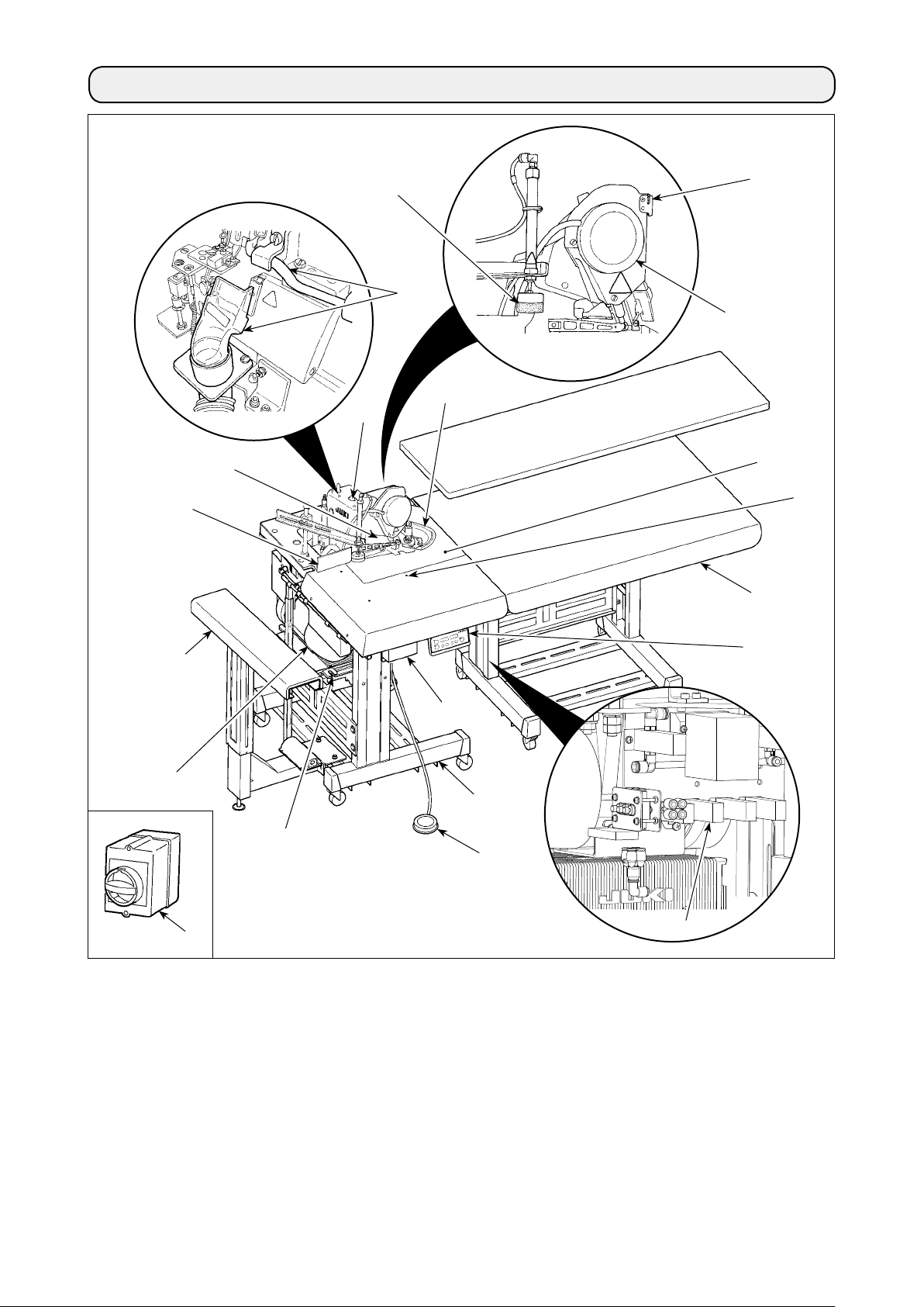
1. CONFIGURATION OF THE MACHINE
J
K
P
R
L
I
F
E
D
Q
C
B
H
G
T
Main body structural mechanism section
A
(table stand, machine support and sewing table
covers)
Stacker unit
B
Sub-table
C
Cloth plate
D
Sewing machine head
E
Cloth guide
F
Control box
G
Sewing machine motor
H
Start switch for the stacker
I
Stacker cloth guide
J
N
A
O
M
Side cutter
K
Dust collector
L
Pneumatic controller
M
Power switch
N
Starting pedal for the sewing machine
O
Thread trimmer presser
P
Cloth feeding air blow
Q
Pause switch
R
Operation panel CP-18
S
Power switch (EU type)
T
(also used as the emergency stop switch)
S
– 1 –
Page 5

2. SPECIFICATIONS
1 Machine head MO-6904S 1-needle overlock machine
1
2 Sewing speed Max. 8,000 sti/min
3 Stitch system JIS E13 (USA standard : 504)
4 Stitch length 0.8 to 4 mm
5 Overedging width 4.0 mm (E), 4.8 mm (F), 5.6 mm (G)
6 Needle ORGAN DC×27 #9 to #14 (Standard : #11)
7 Thread Spun thread #60 (recommended)
8 Chain-off thread
Pneumatic side cutter
cutter
9 Presser foot lift Max. 7 mm (for the machine provided with AK-139)
10 Differential feed
Gathering 1 : 2 (max. 1 : 4), stretching 1 : 0.7 (max. 1 : 0.6)
ratio
11 Sewing specica-
A Cutting curve
tions
B Material size
C Number of plies of material
12 Number of piec-
70 (slacks)
es that can be
stacked
13 Power consump-
420VA or less (operating rate 50 %)
tion
14 Pneumatic pres-
0.5MPa
sure
15 Air consumption 250dm3/min(ANR)
16 Lubricating oil JUKI MACHINE OIL 18
17 Dimensions Type Width Length Height
Short table type 790 mm 575 mm
Long table type 1500 mm
18 Mass of the ma-
chine
Short table type : 110 kg
Long table type : 160 kg
19 Noise - Equivalent continuous emission sound pressure level (LpA) at the workstation :
A-weighted value of 90.5 dB; (Includes KpA = 2.5 dB); according to ISO 10821- C.6.3
-ISO 11204 GR2 at 8,000 sti/min.
- Sound power level (LWA) ;
A-weighted value of 94.0 dB; (Includes KWA = 2.5 dB); according to ISO 10821- C.6.3
-ISO 3744 GR2 at 8,000 sti/min.
*
... In-curve R200 or more
... Out-curve R300 or more
... 400 mm or less (width), 650 mm or more (length)
… Limited to one
(1800 mm
2
(875 mm
*
)
790 mm 880 mm
2
*
)
880 mm
1
*
"sti/min" is an abbreviation for "stitches per minute."
2
*
Machine dimensions including the stacker
– 2 –
Page 6
3. INSTALLATION
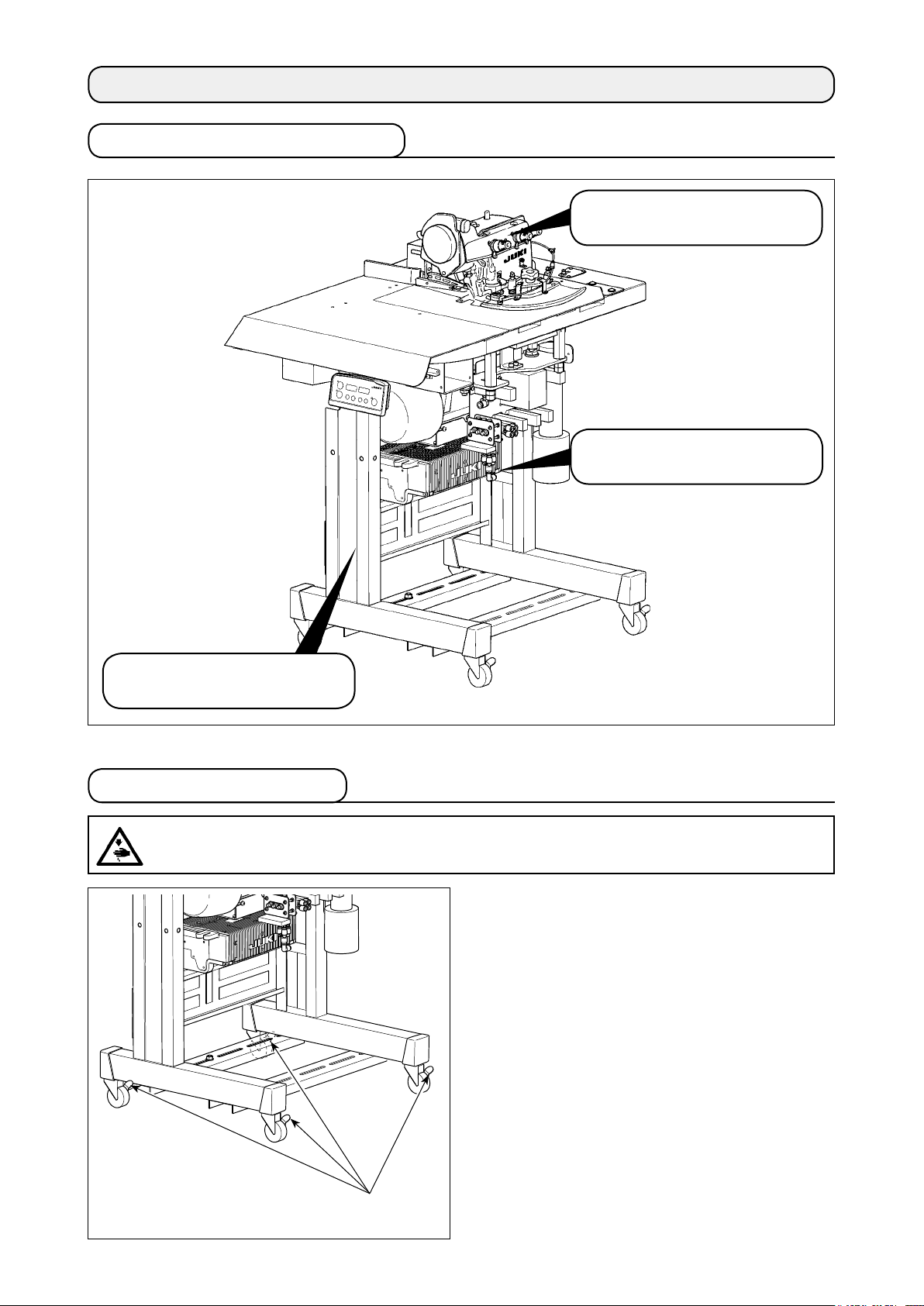
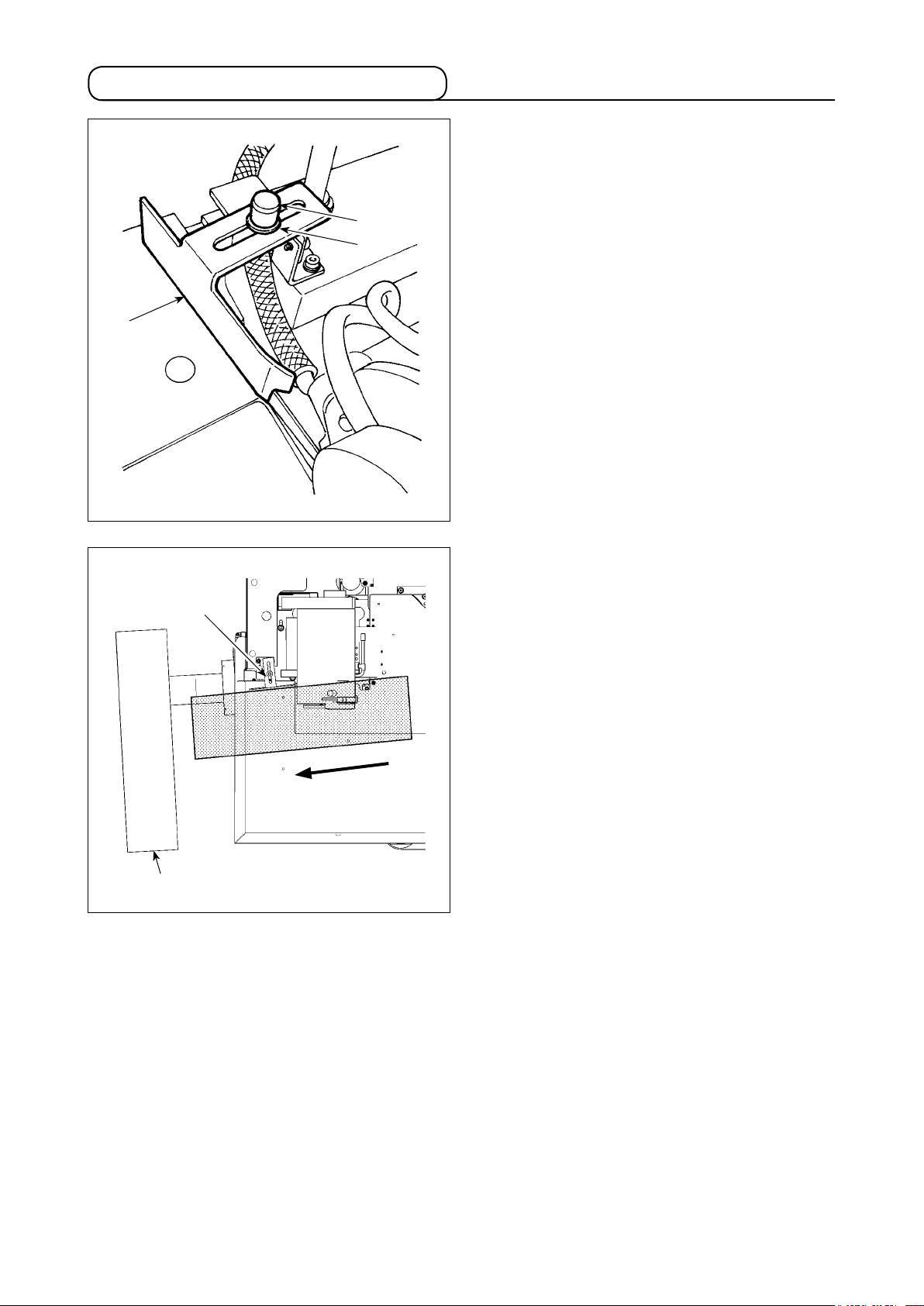
3-1. Removing packing materials
Remove the string which secures
the power cable.
Remove the tape which secures
the cloth plate.
Remove the string which secures
the hose.
3-2. Securing the machine
CAUTION
To avoid possible personal injuries, be sure to move the machine to a level and stable place and lock
casters ❶.
:
❶
– 3 –
Page 7
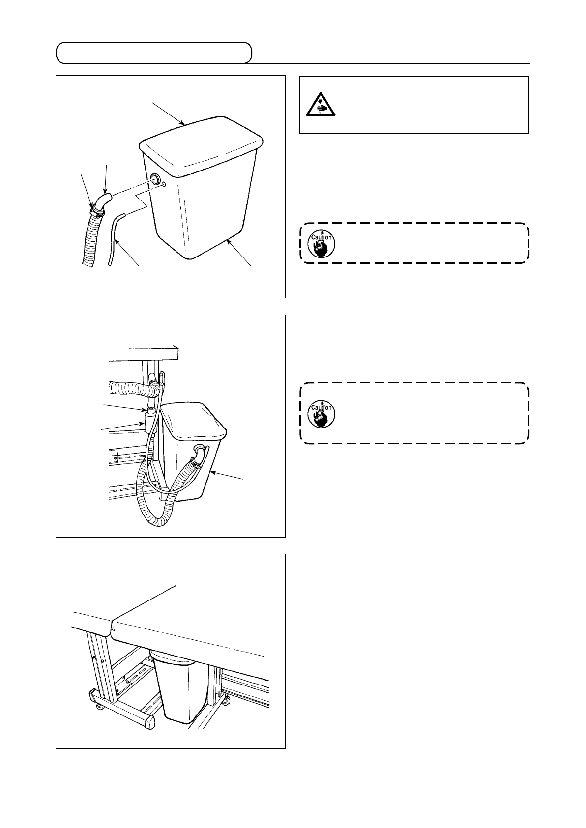
3-3. Installing the dust collector
❹
❷
❺
CAUTION :
If the dust collector is not securely installed, blown-out dust or lint can get in
eyes, resulting in personal injury.
1) Plug the lings blowing hose ❷ and the chain-
off thread blowing hose ❸ into the dust collec-
tion box ❶.
2) Install lter ❹ so that it completely covers the
top of the box.
When dumping dust from the dust collec-
tion box, also clean up lter ❹.
Short table type
❺
❻
❸
❶
Install the dust collection box ❶ to the rear of the
main unit, as shown in the gure.
(Conguration position differs depending upon speci-
cation.)
Conrm that the hose mounting bracket ❺
is completely tightened (the same for other
mounting hardware). Note that the noise
mufer ❻ is optional.
❶
Long table type
– 4 –
Page 8
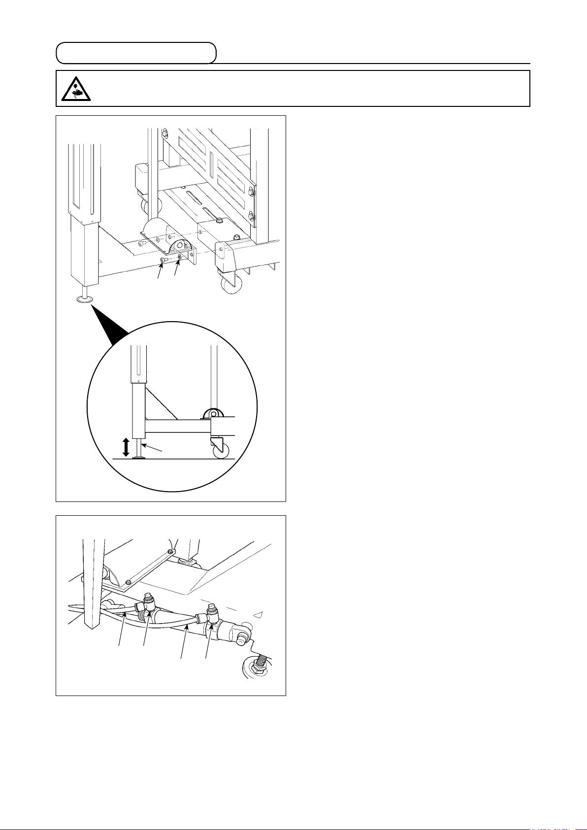
3-4. Installing the stacker
CAUTION
Be sure to carry out installation of the stacker by two or more workers in order to protect against
accidents caused by the stacker unit when it accidentally falls.
:
1) Install the stacker unit on the base with screws
and washers ❷ (at two locations each).
❶
2) Adjust adjusting bolt ❸ to make the support rod
of the stacker parallel to the installing plane.
❷
❶
❹
❺
❸
❻
3) Connect air tube ❹ to joint ❺ and air tube ❻ to
joint ❼ in numerical order.
❼
– 5 –
Page 9
3-5. Installing the stacker cloth guide
❷
❸
❶
Installing stacker cloth guide ❶ on the guide base
with hand screw ❷ and washer ❸.
❹
Adjust the orientation of the cloth guide according to
the clamping position at the stacker unit ❹.
❶
Material feeding direction
– 6 –
Page 10
3-6. Installing the cloth plate and the cloth guide unit
1) Place the cloth plate on the sewing machine
Cloth plate
❶
table.
2) Put the slots (at two locations) in the cloth guide
unit as illustrated in the gure over two studs ❶
(at two locations) of the cloth plate over. Fix the
studs ❶ with washer ❸ and thumb screws ❷.
3) Connect air tube ❹ to joint ❺.
Installing position
❸
Cloth guide unit
❷
❺
❸
❹
❷
– 7 –
Page 11
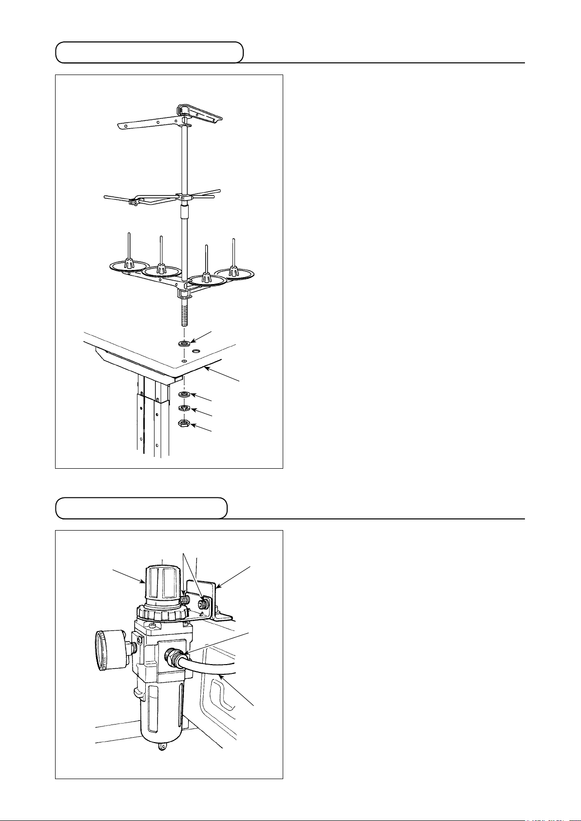
3-7. Installing the thread stand
Washer
Insert the thread stand into the hole in table ❶ with
a washer placed between them and x with the nut
and washers from under the table as illustrated in
the gure at left.
3-8. Installing the regulator
❸
❶
❶
Washer
Spring washer
Nut
❷
❺
Fix regulator ❶ on mounting plate ❷ with screws ❸
(at two locations).
Connect ø8 air tube ❹ to joint ❺.
❹
– 8 –
Page 12
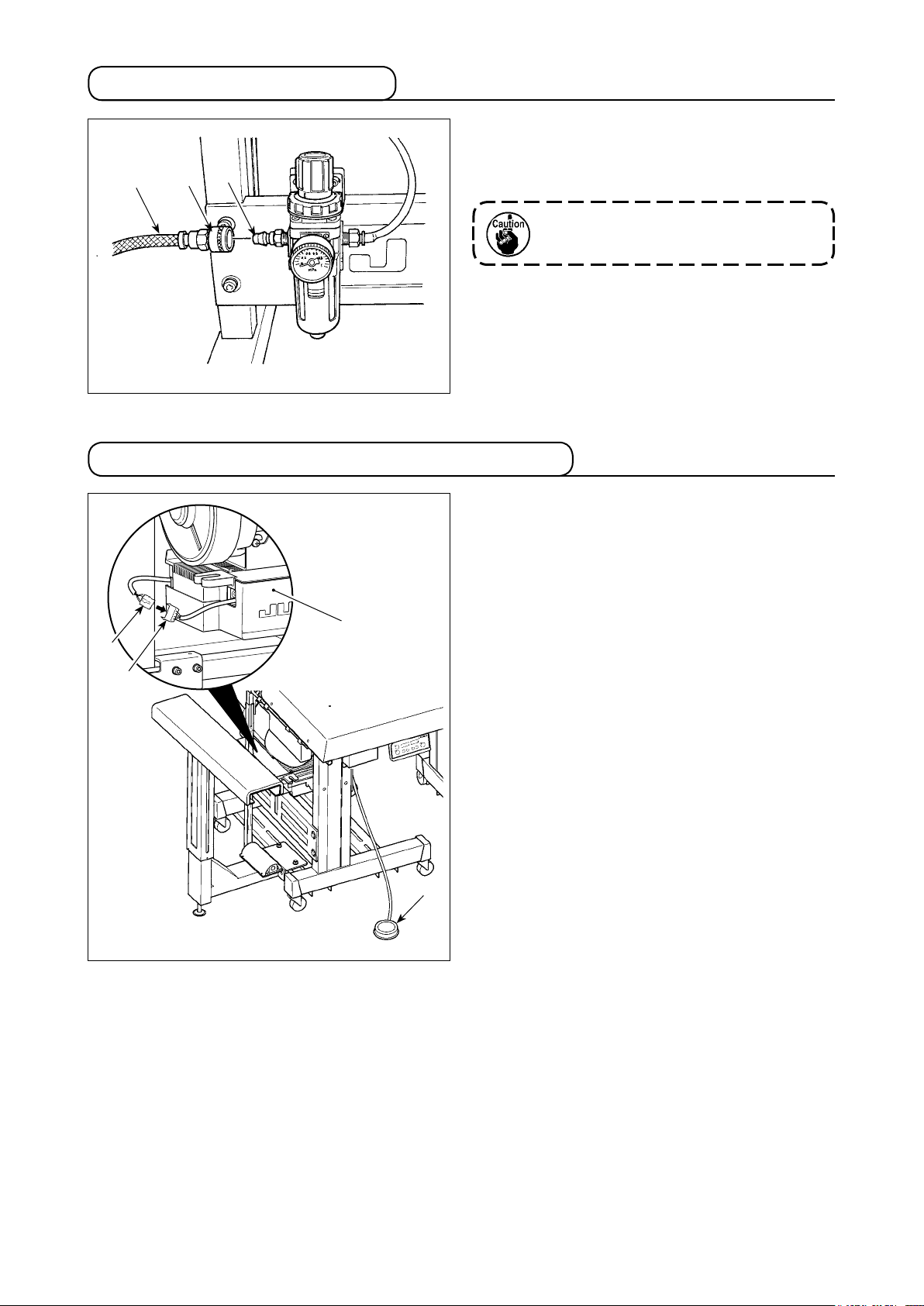
3-9. Connecting the air coupler
Connect the air coupler ❶ supplied with the unit as
an accessory rstly to air hose ❷, secondly to cou-
❷
❶
❸
pler ❸ on the main body side.
Make sure that the pressure gauge of the
regulator reads 0.5 MPa.
3-10. Connecting the starting pedal for the machine
Connector ❷ of starting pedal ❶ to junction connec-
tor ❹ coming from control box ❸.
❷
❸
❹
❶
– 9 –
Page 13
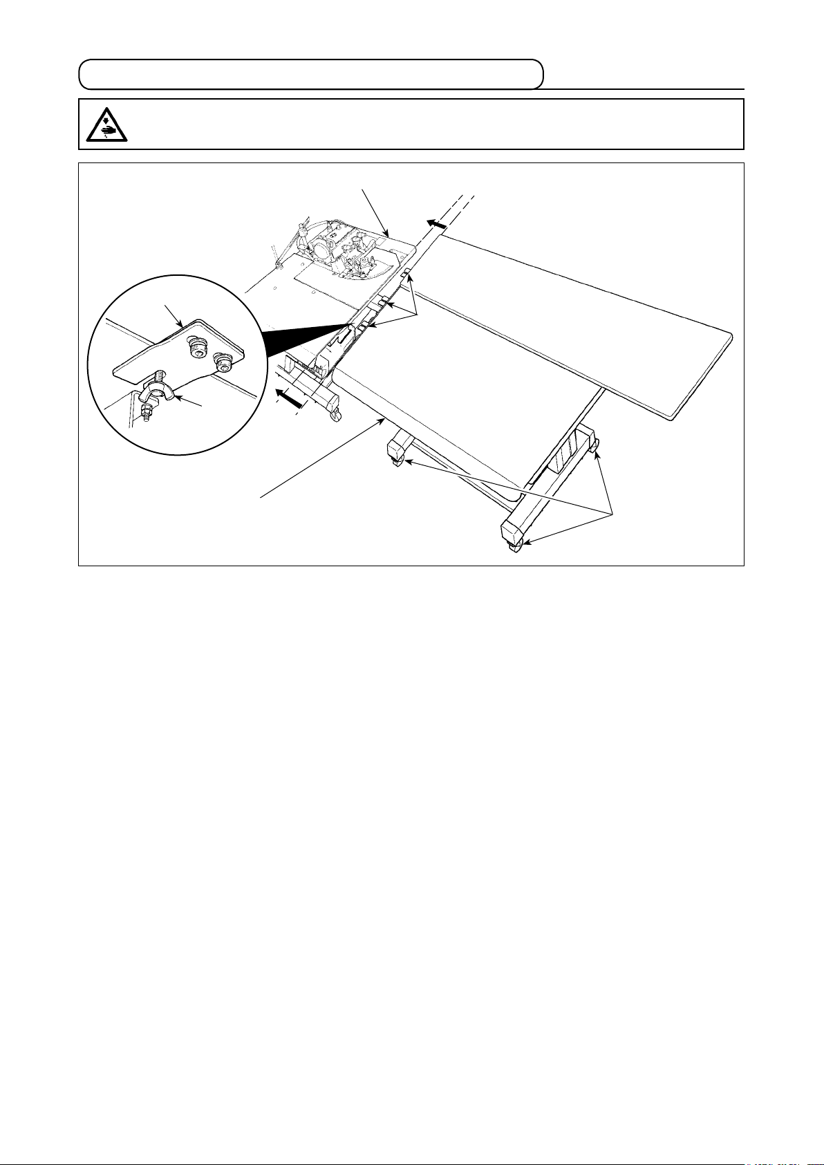
3-11. Joining the sub-table (only for the long table type)
CAUTION
Connect the sub-table to the main-body table taking care not to allow your ngers caught between
them.
:
Main-body table
❹
❶
❷
Sub-table
❸
Butting the sub-table and the main-body table with no clearance provided between them, x clips ❶ (at three
locations) with thumbscrews ❷. Lock casters ❸ (at four locations) to secure the sub-table.
A difference in height between the top face of the main-body table and that of the sub-table may be observed
on some installation site.
If such a difference is observed, adjust so that the tables are same in height with spacers ❹ for adjusting the
height of the clips. (Three spacers are supplied.)
If the sub-table is lower than the main-body table :
・
Add the supplied spacer(s) appropriately.
If the sub-table is higher than the main-body table :
・
Remove spacer ❹ and change with a thinner one.
– 10 –
Page 14
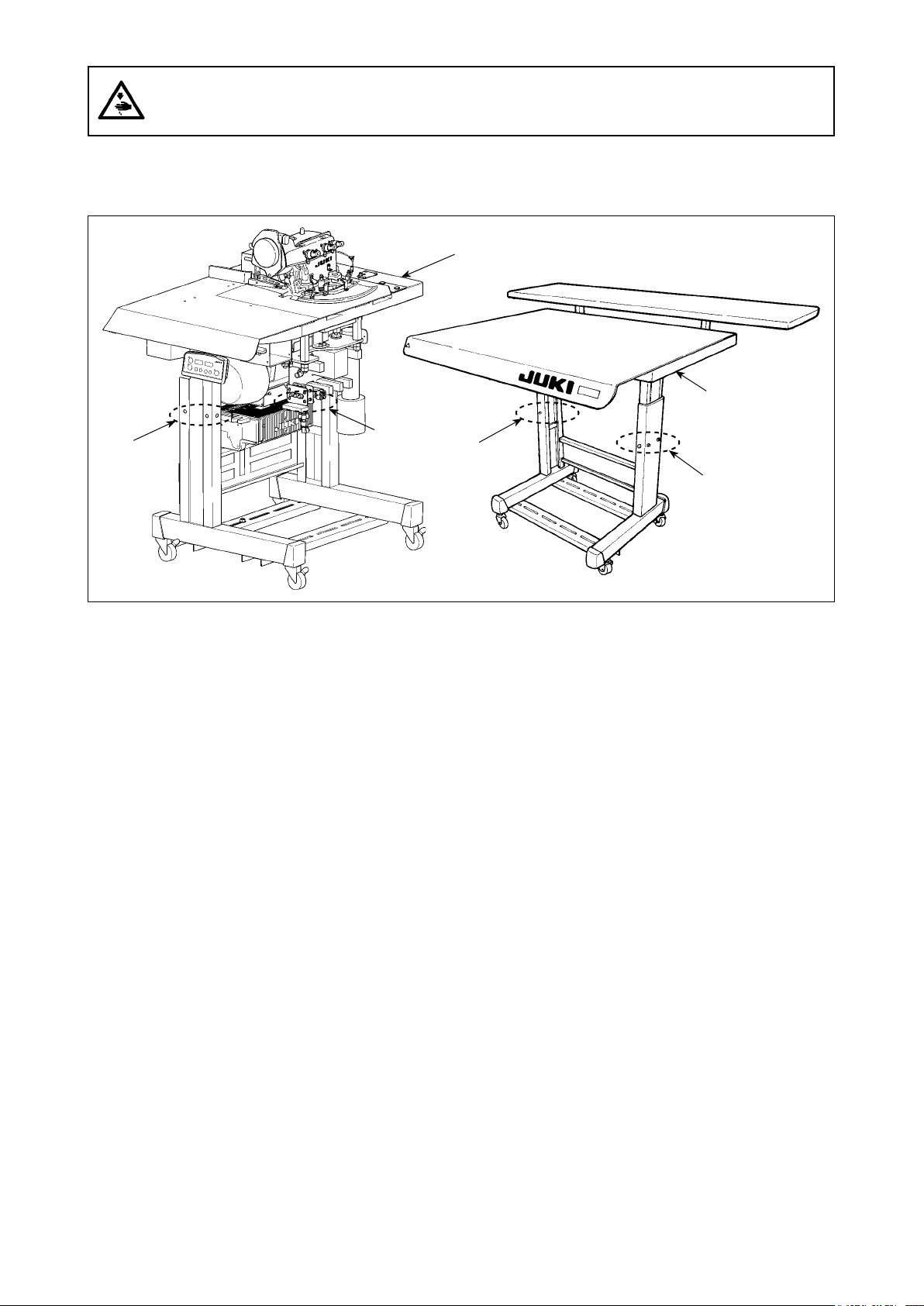
CAUTION :
To protect against possible personal injury or death, be sure to connect the tables while supporting
the machine by four or more workers.
If the difference in height between the sub-table and the main-body table cannot be eliminated with spacer ❹,
adjust the height of the main-body table (or the height of the sub-table).
Main-body table
Sub-table
❺
❺
❻
❻
To adjust the height of the main-body table, loosen screws ❺ that secure the casters (at six locations) to
adjust the height of the main-body table to that of the sub-table and tighten the screws ❺.
To adjust the height of the sub-table, loosen screws ❻ that secure the casters (at six locations) to adjust the
height of the sub-table to that of the main-body table and tighten the screws ❻.
– 11 –
Page 15

3-12. Connecting the power plug
CAUTION
To prevent possible accidents caused by leakage or dielectric strength, an appropriate power plug
shall be installed by a person who has an expert knowledge of electricity. Be sure to connect the
power plug to the receptacle that is well grounded.
:
Connection of the power plug to the power depends on the specications of the product. Adjust the power
plug to the power specications to connect.
In case of the product of single-phase, 200 to 240V specications (CE specications) :
①
Connect the sky-blue and brown wires of the power cord to the power terminal (AC200 to 240V) and the
yellow/green wire to the ground (earth) terminal respectively.
In case of the product of single-phase, 200 to 240V specications (other than CE specications) :
②
Connect the black and white wires of the power cord to the power terminal (AC 200 to 240V), and the
yellow/green wire to the ground (earth) terminal respectively.
In case of the product of 3-phase, 200 to 240V specications :
③
Connect the red, white and black wires of the power cord to the power terminal (AC200 to 240V) and the
yellow/green wire to the ground (earth) terminal respectively.
– 12 –
Page 16

3-13. Installing the cloth receiving board (KM-5) (optional)
❶
❷
❹
❸
❺
1) Fix support rods ❷ on cloth holding table ❶ with wood screws ❸ and washers ❹ (at four locations
each).
2) Fix the cloth holding table mounted with the support rods on the sub-table with screws ❺.
The cloth holding table can be adjusted to four different heights using the xing holes in the support
rod.
❺
– 13 –
Page 17

3-14. Installing the 3-pedal unit (PK-79) (optional)
Connect the connector of the pedal to the junction
connector coming from the control box.
The gure shows differential feed switch ❶, pause
switch ❷ and high-/low-speed changeover switch ❸
from left to right.
❶ ❷ ❸
Differential feed
❶
switch
Pause switch As long as this switch is held depressed, the pause function works. The machine returns
❷
High-/low-speed
❸
changeover switch
As long as this switch is held depressed, the differential feed function works.
to the normal operation (running) by releasing the switch.
Changeover from the high-speed to low-speed can be done only by a depress on this
switch.
The machine returns to the normal operation (running) by releasing the switch.
– 14 –
Page 18

4. PREPARATION
4-1. Caution before operation
CAUTION :
To avoid possible malfunctions and damage of the machine, check the following items.
• Before you put the machine into operation for the rst time, be sure to thoroughly clean it.
• Check to be sure that the voltage has been correctly set.
• Make sure that the power plug is connected properly.
• Never use the machine under a voltage that is different from the specication.
4-2. Lubrication
CAUTION :
To protect against possible personal injury due to abrupt start of the machine, be sure to start the
following work after turning the power off and ascertaining that the motor is at rest.
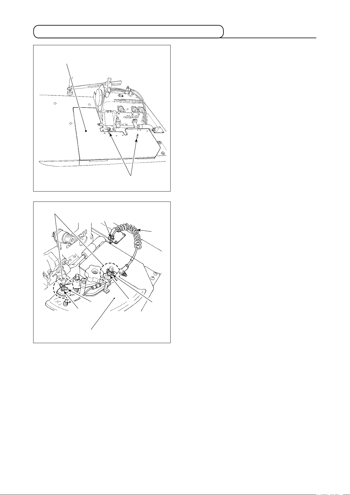
• Lubrication to chain-off thread trimming device
Lubricant inlet
Pipe holder
Knife plate (asm.)
❶
Cloth plate side cover
Remove screw ❶ from the top end of the oil
hose at the rear section of the machine. The
upper limit of the oil quantity is at the top of the
pipe holder.
Oil consumption differs depending on the condi-
tion of use. The oil quantity should be checked
on a daily basis.
As a guide, lubricate the chain-off thread trim-
mer at the following intervals :
❶
❷
❷
· Once a day for the continuous use
· Normally once every three to four days
The chain-off thread trimmer has not been
factory-oiled at the time of delivery.
JUKI MACHINE OIL 18 should be used for
lubrication.
1) Remove oil cap ❶.
2) Pour JUKI MACHINE OIL 18 into the oil reser-
voir.
3) Supply oil until the pointer bar almost reaches
the upper red marker line when oil gauge ❷ is
observed from the side.
If the oil amount pointer bar exceeds the
red marker line, the oil quantity becomes
excessive resulting in oil leakage. Be sure
to stop adding the oil before the red mark-
er line is reached.
– 15 –
Page 19

4-3. Threading the machine
How to remove the cloth plate
★
Remove the cloth plate by holding the cloth plate
guide base.
Do not touch the curve sensor (optional)
mounted on the cloth plate.
To thread the machine head, remove the cloth plate
in advance.
When using an untwisted thread such as
wooly nylon thread or weak thread, do
not wind it round the intermediate thread
guide.
How to thread the needle thread silicon oil
★
tank
When the needle cooler is used. Pass the thread
under the center pawl.
When the needle cooler is not used. Pass the thread
above the center pawl.
– 16 –
Page 20

4-4. Adjusting the pressure of the presser foot and removing the presser foot
1) Adjust the pressure of the presser foot by loos-
❶
❹
❸
❷
ening rst nut ❹ and turning presser foot adjust
screw ❶.
When the adjust screw is turned clockwise, the
pressure will increase. When it is turned coun-
terclockwise, the pressure will decrease.
After the adjustment, be sure to turn nut ❹ with-
out fail.
2) To open presser foot ❷ sidewayd, raise the nee-
dle to the highest position of its stroke and lower
presser bar lifting lever ❸.
4-5. Adjusting the stitch length
CAUTION :
To protect against possible personal injury due to abrupt start of the machine, be sure to start the
following work after turning the power off and ascertaining that the motor is at rest.
❶
1) Slowly turn the handwheel as you keep depress-
2) With the above condition maintained, align the
3) Reset the pushbutton ❶ after setting the dial.
❷
To carry out adjustment, remove the cloth
plate in advance.
ing pushbutton ❶, and you will nd a point at
which the pushbutton goes in farther.
desired scale mark on the handwheel with mark
on the belt cover.
❷
– 17 –
Page 21

4-6. Differential feed mechanism
CAUTION :
To protect against possible personal injury due to abrupt start of the machine, be sure to start the
following work after turning the power off and ascertaining that the motor is at rest.
To carry out adjustment, remove the cloth
plate in advance.
❷
❶
❸
1) Loosen differential feed lock nut ❷. Move lever
up for stretching stitch or down for gathering
❶
stitch.
2) When you want to move the lever ❶ only slight-
ly, use differential feed minute-adjust screw ❸.
3) When the differential feed adjusting lever is
set to graduation S, the machine will perform
stretching with a differential feed ratio of 1 : 0.8.
When the lever is set to graduation 0, the differ-
ential feed ratio between the main feed dog and
the differential feed dog will be 1 : 1.
4) The maximum differential feed ratio for gather-
ing is 1 : 2. The graduations beyond 0 are used
as standard.
5) After the adjustment, securely tighten locknut ❷.
– 18 –
Page 22

5. OPERATION
5-1. Sewing procedure
CAUTION :
• Never start the machine with the eye protector cover raised in order to prevent injury accidents
caused by the needle and the knife.
• The machine becomes hot when it is running continuously or after it has run, never touch the
sewing machine.
❷
❶
1) Press ON button ❶ of the power switch to turn
ON the power.
When the buzzer is kept beeping imme-
diately after turning ON the power, press
OFF button ❷ on the sewing machine to
turn OFF the power since connection of
the cord or power voltage may be wrong.
Indication given after turning the power on
2) After the power to the machine is turned on, the
indication shown below appears on the opera-
tion panel.
The setting item "SEM" ashes on and off.
Fig. A
❸
The machine will not start as long as the
lamp ashes on and off. If this indication
does not appear on the operation panel, turn
off the power to the machine. If the machine
head is not selected correctly, the indication
will not appear on the operation panel.
Refer to the Engineer's Manual for details.
CAUTION :
Never remove the cloth guide while the
machine is ready for sewing in order to
prevent accidents caused by abrupt start
of the machine.
3) When ❸ is pressed while it is ashing on and
off, the machine gets ready for sewing. Insert
the material along the cloth guide from the direc-
tion of the arrow as shown in Fig. A.
When the material is inserted on start sensor ❹
located this side of the throat plate, the machine
starts running to perform sewing.
❹
– 19 –
Page 23

❺
4) Once the material has come out of the sensor,
the machine stops after several stitches. The
stacker operates when the stacker selector
switch or stacker starting switch ❺ is depressed.
CAUTION :
• Do not place hands under the thread
trimmer presser in order to protect
against injury caused by trapping.
• Do not place your face near the stacker
while it is in operation since air is blown
out from the stacker blower outlet ❻.
• Do not place hands near receiving plate
of the stacker unit while the stacker
❼
is in operation.
❼
In the case of an out-curve
❻
When sewing an out-curve part of the ma-
terial, support the material by hand since
seams easily slip off the material edge.
– 20 –
Page 24

❽
5) When sewing is completed, make sure that the
sewing machine has stopped.
Then, press the OFF button ❽ of the power
switch to turn OFF the power.
– 21 –
Page 25

5-2. Explanation of the operation panel
Ⓐ
❷
switch : Used for returning the setting to the initial value.
❶
switch : Used for changing the contents of setting.
❷
When this switch is pressed, changeable positions ash on and off.
By pressing the switch, ashing position shifts in the left direction.
Starting the machine is prohibited while the switch lamp is ashing on and off (setting mode).
❸ ❹ ❺❶ ❻
Ⓑ
switch : Used for changing the contents of setting.
❸
By pressing the switch, ashing position shifts in the right direction.
switch : Used for changing the contents of the selected display (ashing section).
❹
When this switch is pressed, the set value is decreased.
❺
When this switch is pressed, the set value is increased.
switch : Used for determining the contents of setting.
❻
When this switch is pressed, ashing stops and the contents of setting are determined.
The machine enters the sewing mode under which it can start. When the material to be sewn is already
switch : Used for changing the contents of the selected display (ashing section).
placed on the machine under the Automatic mode, E333 will appear on the operation panel. In this case,
the machine is unable to enter the sewing mode. If the curve sensor is set effective, the same phenome-
non occurs when the material is already placed on the machine (E334). If E334 is displayed, check rstly
the neighboring area of the sensor whether the material has been placed on the machine. (The same
phenomenon occurs when dust settles on the sensor. Check the neighboring area of the sensor for
dust.) The operation level can be changed by keeping this switch held pressed for three seconds while
the switch light is ashing on and off.
If the power to the machine is turned off before having taken the aforementioned procedure, the data
changed will not be stored in memory.
Set item indication : Abbreviation of the name of the set item selected is displayed.
Ⓐ
Set contents indication : Content of the set item selected is displayed.
Ⓑ
– 22 –
Page 26

5-3. Description of the pedals and the switches on the machine head
Switch location Name and description of function
Sewing machine starting pedal
❶
The machine starts at the chain-off thread setting speed (at the high
speed if the manual start mode is selected) as long as this switch is
held depressed.
• When the automatic start mode is selected :
When the material is detected, the automatic starting is given priority.
The chain-off thread (starting pedal) is inoperative under the automatic
starting.
• When the manual start mode is selected :
❶
The material detection is inoperative.
The operation same with that taken when the material has come out of
the sensor under the automatic mode is taken by releasing the switch.
Stacker operation switch
❷
When the switch is pressed, the seam is changed to be last one regard-
❷
❸
less of the setting of the number of seams for activating the stacker.
The stacker works regardless of the use/disuse setting of the stacker.
❼ ❻ ❺
❹
Pause switch
❸
When the switch is pressed, E050 is displayed on the operation panel
to stop the machine. After the machine has stopped, the machine is
restored to the on state by pressing the panel switch.
Cloth plate open/close switch
❹
When this switch works, E302 is displayed on the operation panel to
stop the machine. To reset, turn the power off then on.
Low-/high-speed changeover switch (optional)
❺
Changeover from the high-speed to low-speed can be done only by a
depress on this switch.
As long as the switch is held depressed, the low-speed operation is
selected.
Temporary stop switch (optional)
❻
As long as this switch is held depressed, the temporary stop function
works.
The machine returns to the normal operation (running) by releasing the
switch.
Differential feed switch (optional)
❼
As long as this switch is held depressed, the differential feed function
works.
The speed to be employed while the function is working will be the one
for the curve sensor.
– 23 –
Page 27

5-4. List of functions to be set
Item
indication
1 S E M 1 - 1 The number of seams, current seam
2 C n T 0 No. of pcs. counter
3 S T K 0 Use/disuse of the stacker
4 S T d 1 0 Number of delay stitches for the thread trimming
5 S C d 0 Number of delay stitches for the stacker presser
6 S S T 5 5 Number of delay stitches for operating the stacker
7 S b d 5 0 0 Delay time of the stacker blow
8 S b L 7 0 0 Stacker blow time
9 S T F 2 0 Delay time of the thread trimmer presser 0
10 H S P 5 5 0 0 Speed of stitch for the high-speed mode
11 L S P 3 0 0 0 Speed of stitch for the low-speed mode
12 S S P 2 0 0 0 Speed of stitch for the curve sensor
13 d S P 2 0 0 0 Speed of stitch for producing chain-off thread
14 S T r 1 0 0 Start delay time
15 S T P 5 5 Number of delay stitches for stopping the machine
16 A U T 1 Setting of the start mode
17 C U b 1 Curve-mode setting
18 C U 1 1 Curve-mode seam setting
19 C S H 1 Curve differential feed mode setting
20 C S 1 1 Curve differential feed mode seam setting
21 C S S 0 Setting of the number of stitches for starting the
22 C S E 5 0 Setting of the number of stitches for ending the curve
23 d U S 2 0 Setting of the number of stitches for sucking chain-
24 C U r 2 Curl blow time
25 F L U 0 Presser-lifter lift waiting time
26 F L d 0 Presser-lifter lowering waiting time
Contents indication
(initial value)
Description Setting range
presser
and stopping the machine
curve mode
mode
off thread at the beginning of sewing
1 to 9
0 to 9999
0 to 1
0 to 99 stitches
0 to 999 stitches
0 to 999 stitches
0 to 9900 ms
0 to 9900 ms
to
200ms 2
200 to 8000
200 to 8000
200 to 8000
200 to 8000
0 to 9900 ms
0 to 999 stitches
0 to 1
0 to 1
0 to 1
0 to 1
0 to 1
0 to 999 stitches
0 to 999 stitches
0 to 999 stitches
0 to 60 seconds
0 to 9900 ms
0 to 9900 ms
sti/min
sti/min
sti/min
sti/min
Operation
level
*
*
*
*
1
1
1
2
2
1
2
1
1
1
1
2
2
1
2
1
1
1
1
1
1
2
2
2
2
* "sti/min" is an abbreviation for "stitches per minute."
Indication given when changing the operation level
★
L E v 1 Operation level 1 : Normal operation
(When turning the power on)
L E v 2 Operation level 2 : Detailed operation
The operation level can be changed by keeping the switch held depressed for
three seconds.
After the operation level has been changed, the indication which appears when turning on the power
to the machine is shown on the operation panel.
Listing of digitally displays
★
Numeral 0 1 2 3 4 5 6 7 8 9
Digital display
Character A B C D E F G H I J K L M
Digital display
Character N O P Q R S T U V W X Y Z
Digital display
– 24 –
Page 28

5-5. Details of selected functions
Setting of the number of seams (level 1)
①
The number of seams for activating the stacker is set.
The preset number of seams and the current seam are indicated.
Current seam (the ordinal position of the seam being sewn with respect to
the set number of stitches is indicated)
Set value (setting range 1 - 9)
Setting of the No. of pcs. counter (level 1)
②
The number of pieces of products to be sewn is set.
The No. of pcs. counter increments by one every time the stacker operates.
Setting range 0 to 9999
Setting of use/disuse of the stacker (level 1)
③
Whether the stacker is used or not is selected.
0 : Not used
1 : Used (The stacker is controlled when sewing the last seam.)
Setting of the number of delay stitches for the thread trimmer presser (level 2)
④
The number of stitches to be sewn before the thread trimmer presser works after the material has come
out of the sensor is set.
Setting range 0 to 99 stitches
Setting of the number of delay stitches for the stacker presser (level 2)
⑤
The number of stitches to be sewn before the stacker presser works after the thread trimmer presser has
worked is set.
Setting range 0 to 999 stitches
Setting of the number of delay stitches for operating the stacker and stopping the machine (level 1)
⑥
The number of stitches to be sewn before the sewing machine stops after the material has come out of
the sensor is set.
Setting range 0 to 999 stitches
Setting the delay time for the stacker blow (level 2)
⑦
The time to be elapsed before the stacker blow works after the stacker presser has worked is set.
Setting range 0 to 9900 ms
Setting the time for the stacker blow (level 1)
⑧
The length of time during which the stacker blow works after the delay time for the stacker blow has
elapsed.
Setting range 0 to 9900 ms
Setting the delay time for lifting the thread trimmer (level 2)
⑨
The time to elapsed before lifting the thread trimmer presser after the stacker blow has worked is set.
Setting range 0 to 200 ms
– 25 –
Page 29

Setting the speed of stitch for the high-speed mode (level 1)
⑩
The speed of stitch for the high-speed mode is set.
Setting range 200 to 8000 sti/min
Setting the speed of stitch for the low-speed mode (level 1)
⑪
The number of low-speed revolutions is set.
Setting range 200 to 8000 sti/min
Setting the speed of stitch for the curve sensor (level 1)
⑫
The speed of stitch for the section where the curve sensor is effective (from the number of stitches at
which the curve sensor starts to the one at which the sensor stops) is set.
Setting range 200 to 8000 sti/min
Setting the speed of stitch for producing chain-off thread (level 2)
⑬
The speed of stitch to be employed when operating the chain-off thread (starting) pedal.
*
*
*
Setting range 200 to 8000 sti/min
Setting of the start delay time (level 2)
⑭
The time to be elapsed before starting the machine after the material has been detected is set.
Setting range 0 to 9900 ms
Setting of the number of delay stitches for stopping the machine (level 1)
⑮
The number of stitches to be sewn before the machine stops after the normal-seam material (other than
the stack mode) has come out of the sensor is set.
Setting range 0 to 999 stitches
Setting of the start mode (level 2)
⑯
The start mode of the machine is set.
Either the automatic mode by the start sensor or the manual mode by the starting pedal is selected.
0 : Manual mode (The start sensor is inoperative.)
1 : Automatic mode
(The starting pedal is used as the chain-off thread switch.)
Curve mode setting (level 1)
⑰
Whether the curve sensor is used or not is selected.
0 : Not used
1 : Used
*
Curve mode seam setting (level 1)
⑱
Whether the curve sensor is used or not is selected for the specied seam.
0 : Not used
1 : Used
Curve differential feed mode setting (level 1)
⑲
Whether the differential feed mechanism is activated or not by means of the curve sensor is selected.
0 : Not used
1 : Used
* "sti/min" is an abbreviation for "stitches per minute."
– 26 –
Page 30

Curve differential feed mode seam setting (level 1)
⑳
Whether the differential feed mechanism is activated or not by means of the curve sensor is selected for
the specied seam.
0 : Not used
1 : Used
The number of stitches for starting the curve mode (level 1)
The number of stitches to be sewn before the curve mode or differential feed mode starts after the curve
sensor has detected a curved part of the material is set.
Setting range 0 to 999 stitches
The number of stitches for ending the curve mode (level 1)
The number of stitches to be sewn from the start to the end of the curve mode or differential feed mode
is set.
Setting range 0 to 999 stitches
The number of stitches for sucking chain-off thread at the beginning of sewing (level 2)
The number of stitches for sucking chain-off thread at the beginning of sewing is set.
Setting range 0 to 999 stitches
Curl blow output time (level 2)
The time to be elapsed before turning off the curl blow after the machine has stopped is set.
Setting range 0 to 60 seconds
Presser-foot lift waiting time (level 2)
The time to be elapsed before lifting the presser foot after the machine has stopped is set.
(The presser foot automatically goes up when the machine has stopped after stacking.)
Setting range 0 to 9900 ms
Presser-foot lowering waiting time (level 2)
The period of time to be elapsed from the startup of sawing machine to the lowering of the presser foot.
Setting range 0 to 9900 ms
– 27 –
Page 31

5-6. Other settings
(1) Setting of the auto lifter function (optional)
ⒷⒶ
CAUTION :
When the auto-lifter function is used, do not
place your ngers under the presser foot.
When the optional auto-lifter device (AK) is attached,
the auto-lifter function is brought into action.
1) Turn ON the power switch while pressing switch
on the operation panel.
❶
2) LED display is turned to Ⓐ, Ⓑ (FL ON) with
❶
“beep”, and the function of auto-lifter becomes
effective.
3) Turn OFF the power switch, and turn ON the
power switch again to return to the normal
mode.
Air drive display (+24V)
4) Repeat the operation 1) to 3), and LED display
is turned to (FL OFF). Then, the function of auto-lifter does not work.
FL ON : Auto-lifter device becomes effective.
FL OFF : Auto-lifter function does not work.
1. To perform re-turning ON of the power, be sure to perform after the time of one second or more
has passed.
(If ON / OFF operation of the power is performed quickly, setting may be not changed over well.)
2. Auto-lifter is not actuated unless this function is properly selected.
5-7. Initialization of the setting data
Ⓐ
❸❷❶
All contents of function setting of the control box can
be returned to the standard set values.
1) Pressing all switches ❶, ❷ and ❸, turn ON
the power switch.
2) LED displays indication Ⓐ with the sound “peep”,
and initialization starts.
3) The buzzer sounds after approximately one
second (single sound three times, “peep”, “peep”,
and “peep”), and the setting data returns to the
standard setting value.
Do not turn OFF the power on the way of
initializing operation. Program of the main
unit may be broken.
4) Turn OFF the power switch, and turn ON the
power switch again to return to the normal
mode.
– 28 –
Page 32

6. ADJUSTMENT
6-1. Stacker support board adjustment
CAUTION :
To avoid possible accidents because of abrupt start of the machine or the device, turn OFF the power
to the machine, and expel air remaining in the machine by removing the pipe of the air supply before
carrying out assembling or adjustment works.
(1) Adjusting the stacker height
❶
❷
❸
❹
❺
1) Adjust the support board ❶ in accordance with
the type of material to be used.
2) When handle ❷ is loosened, the support board
can be moved up and down. When it is in the
correct position, tighten the handle tightly.
3) Loosen nut ❹. Loosen hexagon head bolt ❸
and adjust work clamp shaft ❺ in accordance
with the support board. After the adjustment, x
the nut by tightening the hexagon head bolt.
(2) Adjusting the orientation of the stacker
Material feeding direction
❷
Loosen nuts ❶ (at two locations) and adjust the ori-
entation of the stacker unit ❷.
If the stacked materials are not neatly
stacked, adjust the orientation of the
stacker unit so that stacker support board
is at right angles to the stacker cloth
❷
guide (material feeding direction).
❶
– 29 –
Page 33

6-2. Adjusting the position of the thread trimmer presser
Loosen screws ❷ (at two locations) which x cylin-
der mounting arm ❶ to adjust the arm to the right or
left. Adjust the thread trimmer presser to the position
at which it clamps the material to be sewn at the
center of its width.
When adjusting, x the thread trimmer
presser so that presser sponge ❸ is
aligned with the top face of the table with
the thread trimming cylinder brought to its
lower position. If the cylinder is inclined,
the thread trimmer presser may fail to
properly clamp the material or a cylinder
failure can occur.
❷
❶
❸
6-3. Adjusting the air blow
1) The amount of the following air blow should be
For the start sensor air blow
and curve sensor air blow
For the side cover air blow
adjusted by means of the speed controller ac-
cording to the type of material and pattern to be
sewn.
❶
❷
For material feeding
❹
❶ ❷ ❸
❸
❺
❻
Cloth feeding air blow
❶
Cloth feeding air blow
❷
Cloth feeding air blow
❸
Side cover air blow
❹
Start sensor air blow
❺
Curve sensor air blow (optional)
❻
2)
The air blowing amount is reduced by turning the
adjusting knob clockwise.
3)
The air blowing direction of the cloth feeding blow
can be changed by loosing the M4 nut mounted
underside of the table.
After changing the air blowing direction, be sure
to tighten the nut to x it. In addition, check to be
sure that the air hoses are fully tightened with a
clip band.
– 30 –
Page 34

6-4. Adjusting the edge guide
CAUTION :
Turn OFF the power before starting the work so as to prevent accidents caused by abrupt start of the
sewing machine.
❹
❸
Material
❷
❶
❸
1) Edge guide ❶ works to adjust the overedging
width of the material. Adjust the overedging
width by adjusting edge guide ❶ to the right or
left using screws ❷.
2) Curl guide ❸ works to prevent the material edge
from curling. Adjust the curl guide with screw ❹
according to the cloth thickness.
Overedging width of the material
– 31 –
Page 35

6-5. Adjusting the cloth guide
CAUTION :
Turn OFF the power before starting the work so as to prevent accidents caused by abrupt start of the
sewing machine.
Fig. A
❷
❸
❶
❹
1) By loosening two screws ❷, cloth guide posi-
tion can be adjusted in the direction shown by
arrow. After the adjustment of overedging width
of the material with edge guide ❹, adjust the
surface of edge guide ❹ and that of cloth guide
(Fig. A) are ush with each other.
❸
2) If the knob ❶ is turned to the right, cloth guide
is lowered, and if the knob is turned to the
❸
left, cloth guide is raised. Make adjustment ac-
cording to the cloth thickness.
❸
6-6. Regulator adjustment
CAUTION :
Turn OFF the power before starting the work so as to prevent accidents caused by abrupt start of the
sewing machine.
❶
Tightening adjustment screw ❶ weakens the chain-
off thread suction power; loosening the screw
strengthens it.
– 32 –
Page 36

6-7. Adjusting the cloth chip suction force
CAUTION :
Turn OFF the power before starting the work so as to prevent accidents caused by abrupt start of the
sewing machine.
❶
Tightening adjustment screw ❶ weakens the chain-
off thread suction power; loosening the screw
strengthens it.
The suction force for the cloth chip collec-
tor and the dust collector mounted on the
upper looper bracket is adjusted by means
of the same adjusting screw.
– 33 –
Page 37

6-8. Adjusting the sensors
Once the cloth guide has been adjusted to 5 mm position, check to be sure that the numeric value on the
main digital display shown on the amplier is 8000 or more when no material is placed under the sensor unit,
and that the numeric value on the main digital display is 6200 or less when the material is placed under the
sensor unit.
If the aforementioned requirements are not satised, the machine can malfunction. It is therefore
necessary to adjust the threshold of the amplier.
❶
Startup sensor amplier ❶ is located at the position
as illustrated in the gure.
Amplier ❷ for the curve sensor is located at the
rightmost position on the top face of the cloth plate.
❷
DPC indicator
Turns ON when Dynamic power control is
effective.
* This function is not used by this sewing machine.
L/D indicator
Setting status of L/D between "ON (L)
when the light enters" and "ON (D) when
the light is shielded" is displayed.
button
Set value for the light projecting
power is automatically set.
OUT Indicator
Turns ON when Output is ON.
Threshold
Green digital display
+/- UP/DOWN button
This button is used for nely adjusting the threshold
and changing the conguration parameter.
L/D button
△
This button is used for changing over the status
of L/D between "ON (L) when the light enters" and
"ON (D) when the light is shielded".
* The startup sensor has been set to the state "ON (D)
when the light is shielded". The curve sensor has been
set to the state "ON (L) when the light enters".
ST indicator
Turns ON when Smart tuning is in progress.
Amount of light
received
Red digital display
MODE button
□
This button is used for
changing over the mode
between the detection
mode and the setting
mode.
– 34 –
Page 38

(1) Setting thresholds for the start sensor and curve sensor
It is possible to detect two amounts of light received; i.e., the amount of light received when there is no material and that when there is a material. The intermediate value between those two amounts of light received
can be set as the threshold.
1)
Adjust the clearance provided between the cloth
Without-material state
guide and cloth plate to 5 mm before starting
adjustment.
Turn on the power to the machine.
Be sure to carry out adjustment under the
machine setting mode in order to prevent
accidents caused by abrupt start of the
machine.
Press once.
With-material state
Material
2) Open the sensor amplier cover.
3) Place no object to be detected at the sensor
irradiation position.
4) Press the button once.
is displayed with lighted.
5) Place a sheet of white paper (substitute for
the material) at the sensor irradiation positions
respectively on the cloth guide and on the cloth
plate. Then, press the button once.
is displayed with lighted.
6) The setting is completed when the screen is re-
stored to the one on which the specied thresh-
old and the current amount of light received are
displayed.
7) Close the sensor amplier cover.
8) Insert the material into the cloth guide unit.
Check to be sure that the amount of light re-
ceived do not exceed the threshold.
Press once.
Threshold Amount of light
received
– 35 –
Page 39

7. MAINTENANCE
7-1. Adjusting the knife
CAUTION :
• To protect against possible personal injury due to abrupt start of the machine, be sure to start the
following work after turning the power off and ascertaining that the motor is at rest.
• To protect against possible personal injury, never touch the blade of the knife with ngers and
hands.
• To prevent possible accidents caused by inexperienced persons and those resulting from
maladjustment, adjustment work should only be carried out by maintenance personnel who have
received safety training and are familiar with the sewing machine.
❹
❸
To adjust the extent of cutting uff at the overedged
edge of the material :
1) Loosen setscrew ❶. Tighten the setscrew with
lower knife ❷ pressed to the left.
2) Loosen setscrew ❸. Move upper knife as far as
needed and secure with the setscrew ❹.
3) Lower the upper knife to its lower end position.
Loosen setscrew ❶ to adjust so that the lower
knife comes in contact with the upper knife, then
tighten setscrew ❶.
❶
7-2. Cleaning the machine head
CAUTION :
To protect against possible personal injury due to abrupt start of the machine, be sure to start the
following work after turning the power off and ascertaining that the motor is at rest.
❷
1. Be sure to tighten screw ❶ before oper-
ating machine.
2. After the completion of adjustment,
make the knives cut a thread to check
for sharpness of the knives.
Clear lint from inside the looper cover and the needle
bar and components about once or twice a day. If
not, oil may leak the sewing material will be soiled.
– 36 –
Do not wipe the coated surface of the ma-
chine head with lacquer thinner. Doing so
will damage the coated surface.
Page 40

7-3. Checking the cartridge lter and replacing it
1. After a long period of usage, cartridge lter ❶
❷
❸
❹
may become clogged with dust.
If the machine is left in this state, the dirty oil
may fail to pass through cartridge lter ❶, and
the machine may wear out abnormally, or a sei-
zure may result.
Cartridge lter ❶ should normally be checked
※
once every six months, and cleaned or replaced
accordingly.
7-4. Changing the machine oil
❶
2. How to inspect the cartridge lter and replace it.
1) Remove rst oil discharging screw ❷.
2) Remove screws ❸, and lift top cover ❹ just
above until it comes off.
If top cover ❹ is shifted sideward, the oil
amount pointer bar and the cartridge lter
may be damaged.
3) Remove cartridge lter ❶ and check it. If the
lter is found to be abnormal, clean the relevant
components, or replace cartridge lter ❶.
4) Re-insert cartridge lter ❶ into its proper posi-
tion and return the cover. Do not forget to put
back the setscrews and tighten them up.
CAUTION :
Turn OFF the power before starting the work so as to prevent accidents caused by abrupt start of the
sewing machine.
1) Use JUKI MACHINE OIL 18 in the machine
head.
❶
2) To change the oil, rst drain the oil out by un-
screwing screw ❶ on the tip of the oil drain hose
connected to the oil pan. At this time, remove
the cover from the oil inlet hole on top of the ma-
chine head.
3) Refer to
lubricate the machine.
"4-2. Lubrication" p.15
for how to
– 37 –
Page 41

7-5. Changing needles
CAUTION :
To protect against possible personal injury due to abrupt start of the machine, be sure to start the
following work after turning the power off and ascertaining that the motor is at rest.
❶
❷
The standard needle is DC×27 #11. You can also
use the DC×1 needle. In this case, however, the
clearance provided between the needle and the
looper may be required to be adjusted. If sewing
need to be carried out with a nely adjusted thread
tension, use the DC×27 needle.
1) Bring needle clamp ❶ to the highest position.
2) Loosen needle clamp screw ❷, and fully insert
the needle into the needle clamp hole with the
needle recess facing backwards as viewed from
the operator’s side.
3) Tighten the needle clamp screw ❷.
7-6. Drainage of lter regulator
CAUTION :
Turn OFF the power before starting the work so as to prevent accidents caused by abrupt start of the
sewing machine.
1) Drainage of regulator ❶ must take place before
usage, and water must be eliminated.
(Loosen knob ❷, then drain the water.)
2) Be careful about moisture as it is harmful to air
control system.
If the amount of water is enormous, check
in addition the main unit of the compres-
sor for water.
❶
❷
– 38 –
Page 42

7-7. Cautions for the compressed air supply (source of supply air) facility
As large as 90 % of failures in pneumatic equipment (air cylinders, air solenoid valves) are caused by "con-
taminated air."
Compressed air contains lots of impurities such as moisture, dust, deteriorated oil and carbon particles. If
such "contaminated air" is used without taking any measures, it can a cause of troubles, inviting reduction in
productivity due to mechanical failures and reduced availability.
Be sure to install the standard air supply facility shown below whenever the machine provided with pneumat-
ic equipment is used.
Standard air supply facility to be prepared by the user
Air compressor
After cooler
Auto-drain
Air tank
Main line lter
Auto-drain
Air dryer
Mist separator
Filter regulator
Air solenoid valve
Quality of the air supply
When the supply air contains a considerable amount of moisture
Ambient environment
When our machine is installed at a place where the temperature greatly
changes in the morning and in the evening from that in the daytime or
freeze is like to occur
In the aforementioned cases, be sure to install an air dryer.
When the supply air contains a considerable amount of carbon and dust
(Most troubles in the air solenoid valves are caused by carbon.)
Be sure to install a mist separator.
Standard equipment supplied by JUKI
Air cylinder
Cautions for main piping
• Be sure to slope main piping by a falling gradient of 1 cm per 1 m in the direction of air ow.
• If the main piping is branched off, the outlet port of the compressed air should be provided at the
top part of the piping using a tee in order to prevent drain settling inside the piping from owing
out.
• Auto drains should be provided at all lower points or dead ends in order to prevent the drain from
settling in those parts.
– 39 –
Page 43

7-8. Dust collector box
CAUTION :
Turn OFF the power before starting the work so as to prevent accidents caused by abrupt start of the
sewing machine.
1) Throw away waste cloth chips inside the dust collector box at least once a day. At this time, also clean
up the lter.
2) Fine cloth chip adhere to the suction port inside the box; blow them away with an air gun.
3) If a great deal of lint adheres to the intake, the suction power may be reduced.
7-9. Cleaning the sensor
CAUTION :
Turn OFF the power before starting the work so as to prevent accidents caused by abrupt start of the
sewing machine.
When dust gathers around irradiating position for the
start sensor and curve sensor, the sensor may make
❷
erroneous detection resulting malfunction of the ma-
chine. To avoid this, be sure to remove dust from the
following four parts by blowing air with an air gun.
❶
❹
❸
• Irradiating point ❶ for the start sensor on the
top face of the cloth plate
• Irradiating point ❷ for the curve sensor on the
top face of the cloth plate
• Irradiating point ❹ for the start sensor on the
throat plate base A
(Remove the cloth plate to carry out the dust
removal procedure.)
• Irradiating point ❺ for the start sensor on the
rear face of the cloth plate
(Remove the cloth plate to carry out the dust
removal procedure.)
❸
❺
Rear face of the cloth plate
– 40 –
Page 44

7-10. Consumable parts to be replaced
CAUTION :
• Turn OFF the power before starting the work so as to prevent accidents caused by abrupt start of
the sewing machine.
• To protect against possible personal injury, never touch the blade of the knife with ngers and
hands.
• To prevent possible accidents caused by inexperienced persons and those resulting from
maladjustment, adjustment work should only be carried out by maintenance personnel who have
received safety training and are familiar with the sewing machine.
The following parts are consumables. Be sure to periodically replace them with new ones.
Side cutter block
• Side cutter block
(Part number : MAT02503000)
If the block is not periodically replaced with a
new one, it can wear out to fail to trim chain-
off thread sharply, affecting the quality of thread
trimming at the end of sewing.
• Thread trimmer presser sponge
(Part number : 18072603)
If the sponge is not periodically replaced with a
new one, it can fail to clamp the material ade-
quately, affecting the quality of thread trimming
at the end of sewing.
Thread trimmer
presser sponge
– 41 –
Page 45

7-11. Replacing the fuse
DANGER :
To prevent personal injuries caused by electric shock hazards or abrupt start of the sewing machine,
remove the cover after turning OFF the power switch and a lapse of 5 minutes or more. To prevent
personal injuries, when a fuse has blown out, be sure to replace it with a new one with the same
capacity after turning OFF the power switch and removing the cause of the blown-out of the fuse.
1) Press the OFF button of the power switch to turn
OFF the power after conrming that the sewing
machine has stopped.
2) Draw out the power cord coming from the power
plug socket after conrming that the power
switch is turned OFF. Perform the work of step 3)
after conrming that the power has been cut and
it has passed for 5 minutes or more.
3) Loosen setscrew ❷ in cover ❶. Open cover ❶.
❷
Be sure to open/close cover ❶ while put-
ting a hand on it.
❶
4) Remove all the cables which are connected to
the control box.
5) Loosen setscrews ❹ of control box mounting
plate ❸. Detach the control box from the motor.
❹
❸
– 42 –
Page 46

[ Replacing fuse on PWR-T circuit board ]
(Caution) The illustration below shows the PWR-T PCB. The type of PCB differs by destination.
❺
❻
6) Holding the glass section of fuse ❺, remove the fuse.
(Caution) There is a risk of electrical shock when removing the fuse. Be sure to remove the fuse after LED
has totally gone out.
❻
5) Be sure to use a fuse with the designated capacity.
: 3.15 A/250 V Time-lag fuse
❺
(Power circuit protective fuse)
Part number: KF000000080
8) Install the control box to the motor.
9) Connect all the cables to the control box. (Refer to
connectors" p.44
.)
"7-13. Destination of connection for input/output
7-12. Adjusting the belt tension
15mm(9.8N)
Tension
adjust nuts
The belt tension should be adjusted by turning the
tension adjust nuts to change height of the motor,
so that the belt sinks down by about 15 mm (9.8N)
when it is depressed by band at the center of the belt
span.
If the belt tension is not adequate, the sewing ma-
chine may not rotate with consistency at the low- to
medium-speed operation.
The belt can increase in length as a result
of use. Be sure to periodically check and
adjust the belt tension appropriately.
– 43 –
Page 47

7-13. Destination of connection for input/output connectors
CAUTION :
• To prevent personal injury caused by abrupt start of the sewing machine, carry out the work after
turning OFF the power switch and a lapse of 5 minutes or more.
• To prevent damage of device caused by maloperation and wrong specications, be sure to
connect all the corresponding connectors to the specied places.
• To prevent personal injury caused by maloperation, be sure to lock the connector with lock.
• As for the details of handling respective devices, read carefully the Instruction Manuals supplied
with the devices before handling the devices.
Solenoid valves and sensors used with ASN-690 are connected to the connectors inside the control box as
described below: Connection state of the connectors can be checked by loosening front-cover xation screws
and opening the front cover.
❶
❷
❼
CN42 Curve sensor
❶
CN54 Startup sensor
❷
CN30 Motor signal connector
❸
CN48 Connector for the cloth plate open/close switch and halt switch
❹
CN38 Operation panel CP-18
❺
CN39 Connector for pedal junction cable
❻
CN56 Connector for solenoid valve
❼
CN36 Connector for solenoid valve
❽
CN37 Connector for solenoid valve
❾
CN201 Connector for starting pedal
CN206 Connector for 3-pedal unit (optional)
❽
❾❻❺❹❸
– 44 –
Page 48

7-14. Error codes
In case of the following, check again before you judge the case as trouble.
Phenomenon Cause Corrective measure
When tilting the sewing machine, the
buzzer beeps and the sewing machine cannot be operated.
Solenoids for thread trimming, reverse
feed, wiper, etc. fail to work. Hand
lamp does not light up.
When tilting the sewing machine
without turning OFF the power switch,
action given on the left side is taken
for safety sake.
When the fuse for solenoid power
protection has blown out
Tilt the sewing machine after turning
OFF the power.
Check the fuse for solenoid power
protection.
Presser foot does not go up even
when auto-lifter device is attached.
Sewing machine fails to run. Motor output cord (4P) is disconnect-
Auto-lifter function is OFF. Select “FL ON” by auto-lifter function
selection.
Cord of auto-lifter device is not connected to connector (CN37).
ed.
Connector (CN30) of motor signal
cord is disconnected.
Connect the cord properly.
Connect the cord properly.
Connect the cord properly.
In addition, there are the following error codes in this device. These error codes interlock (or limit function)
and inform the problem so that the problem is not enlarged when any problem is discovered. When you re-
quest our service, please conrm the error codes.
[Checking procedure of the error code]
Ⓑ
1) Turn ON the power switch with
switch ❸ held pressed.
2) The latest error number is displayed
on indicator Ⓑ with a blip.
3) Contents of previous errors can be
checked by pressing switch ❸ or
switch ❹.
❹❸
(When the conrmation of the contents
of previous error advanced to the last,
the warning sound peeps in single
tone two times.)
(Caution) When switch ❸ is pressed, the previous error code of the currently displayed one is
displayed. When switch ❹ is pressed, the next error code of the currently displayed one
is displayed.
– 45 –
Page 49

7-15. Error code list
No.
Description of error detected
E000
E003 Disconnection of synchro-
E004 Synchronizer lower position
E005 Synchronizer upper position
E007 Overload of motor • When the machine head is locked.
E050 The pause switch is
E070 Slip of belt • When the machine head is locked.
E071 Disconnection of motor
E302 Opening of the cloth plate
E333 The material is inserted on
E334 The material is inserted on
Execution of data initialization
(This is not the error.)
nizer connector
sensor failure
sensor failure
pressed
output connector
is detected.
the start sensor.
the curve sensor.
Cause of occurrence expected Items to be checked
• When the machine head is changed.
• When the initialization operation is executed.
• When position detection signal is not input
from the sewing machine head synchronizer.
• When the synchronizer has broken.
• Belt is loose.
• Machine head is not proper.
• Motor pulley is not proper.
• When sewing extra-heavy material beyond
the guarantee of the machine head.
• When the motor does not run.
• Motor or driver is broken.
• The connector of the switch has come off. • Check the connector of the pause switch
• Belt is loose.
• Disconnection of motor connector • Check the motor output connector for loose
• The cloth plate is not installed on the table. • Check whether the cloth plate is set on the
• Dust on the sensor
• Sensitivity of the sensor
• Check the synchronizer connector (CN33,
CN43) for loose connection and disconnection.
• Check whether the belt is loose.
• Check whether the synchronizer cord has
broken since the cord is caught in the machine head.
• Check the belt tension.
• Check the setting of the machine head.
• Check the setting of the motor pulley.
• Check whether the thread has been entangled in the motor pulley.
• Check the motor output connector (4P) for
loose connection and disconnection.
• Check whether there is any holdup when
turning the motor by hand.
for loose connection and disconnection.
• Check whether there is any holdup when
turning the motor by hand.
• Check the belt tension.
connection and disconnection.
table
• Dust around the sensor
• Adjustment of the sensitivity of the sensor.
• Setting of the L/D
E730 Encoder failure • When the motor signal is not properly
inputted.
E731 Motor hole sensor failure
E733 Inverse rotation of motor • This error occurs when the motor is run-
ning at 500 rpm or more in the opposite direction of that of rotation indication during
motor is running.
E811 Overvoltage • When voltage higher than guaranteed one
is inputted.
• 220V has been inputted to SC-510 of 110V
specications.
• 400V is applied to the box of 220V (230V).
E813 Low voltage • When voltage lower than guaranteed one
is inputted.
• 110V has been inputted to SC-510 of 220V
specications.
• 110V is applied to the box of 220V.
• Inner circuit is broken by the applied overvoltage.
E924 Motor driver failure • Motor driver has broken.
• Check the motor signal connector (CN30)
for loose connection and disconnection.
• Check whether the motor signal cord has
broken since the cord is caught in the machine head.
• Connection of the encoder of main shaft
motor is wrong.
• Connection for the electric power of main
shaft motor is wrong.
• Check whether the applied power voltage
is higher than the rated voltage + (plus)
10% or more.
• Check whether 110V/220V changeover
switch is improperly set.
In the aforementioned cases, POWER p.c.b
is broken.
• Check whether the voltage is lower than
the rated voltage – (minus) 10% or less.
• Check whether 110V/220V changeover
switch is improperly set.
• Check whether fuse or regenerative resistance is broken.
– 46 –
 Loading...