

Page 1

APW-895/IP-420
INSTRUCTION MANUAL
* "CompactFlash(TM)" is the registered trademark of SanDisk Corporation, U.S.A.
Page 2

CONTENTS
I. CAUTIONS BEFORE OPERATION .................................................................................. 1
II. CONFIGURATION OF THE MACHINE ...........................................................................2
III. SPECIFICATIONS ........................................................................................................... 3
1. MECHANICAL SPECIFICATIONS ........................................................................................................ 3
2. ELECTRICAL SPECIFICATIONS ......................................................................................................... 3
IV. INSTALLATION ...............................................................................................................4
1. REMOVING PACKING MATERIALS .................................................................................................... 4
2. SECURING THE MACHINE .................................................................................................................. 4
3. CONNECTING THE FOOT PEDAL ...................................................................................................... 5
4. CONNECTING THE AIR COUPLER .................................................................................................... 5
5. CONNECTING THE POWER PLUG .................................................................................................... 6
6. ASSEMBLING THE THREAD STAND AND ATTACHING IT TO THE MACHINE ............................... 7
7. INSTALLING SP-46 (CLAMP BAR STACKER) (OPTIONAL PART NO. : 40058952) ........................ 7
8. INSTALLING SP-47 (ROLLER STACKER) (OPTIONAL PART NO. : 40058953) ............................... 8
9. REMOVING THE HEAD FIXING PLATE .............................................................................................. 9
10. INSTALLING THE SUB-TABLE ........................................................................................................... 9
11. INSTALLING OPERATION PANEL IP-420 ........................................................................................... 9
12. LUBRICATING THE OIL TANK .......................................................................................................... 10
13.
INSTALLING SA-120 (INTERLINING SUPPLYING DEVICE) (OPTIONAL PART NO. : 40045772)
14. ADJUSTMENT OF SA-120 (INTERLINING SUPPLYING DEVICE) (OPTIONAL PART NO. :
40045772) ........................................................................................................................................... 12
.... 11
V. PREPARATION OF THE SEWING MACHINE ..............................................................13
1. HOW TO OPERATE THE SEWING MACHINE HEAD ....................................................................... 13
(1) How to attach the needles .............................................................................................................. 13
(2) Thread used .................................................................................................................................... 13
(3) How to pass the needle thread ....................................................................................................... 14
2. HOW TO REMOVE THE SEWING TABLE ......................................................................................... 15
(1) When replacing the bobbin thread .................................................................................................. 15
(2) Cautions to be taken when the sewing tables are removed ........................................................... 16
3. HOW TO WIND THE BOBBINS .......................................................................................................... 17
4. HOW TO THREAD THE BOBBIN CASE ............................................................................................ 18
5. HOW TO INSTALL THE BOBBIN CASE ............................................................................................ 18
6. HOW TO ADJUST THE THREAD TENSION...................................................................................... 19
7. SETTING THE MATERIAL TO BE SEWN .......................................................................................... 20
(1) Setting a garment body .................................................................................................................. 20
8. ADJUSTING THE MATERIAL GUIDE ................................................................................................ 20
VI. HOW TO USE THE OPERATION PANEL ....................................................................21
1. PREFACE ............................................................................................................................................ 21
2. BASIC OPERATION OF THE OPERATION PANEL (IP-420) ............................................................ 24
(1) Conguration of IP-420 ................................................................................................................... 24
(2) Buttons used in common ................................................................................................................ 25
(3) Basic operation ............................................................................................................................... 25
3. EXPLANATION OF THE BASIC SCREEN ......................................................................................... 28
(1) Input screen (Independent sewing mode)....................................................................................... 28
(2) Sewing screen (Independent sewing mode) .................................................................................. 29
i
Page 3

(3) Input screen (Alternate sewing mode) ............................................................................................ 30
(4) Sewing screen (Alternate sewing mode) ........................................................................................ 31
(5) Input screen (Cycle sewing mode).................................................................................................. 32
(6) Sewing screen (Cycle sewing mode) ............................................................................................. 33
4. USING THE COUNTER ...................................................................................................................... 34
(1) Setting procedure of the counter..................................................................................................... 34
(2) Releasing procedure of count-up .................................................................................................... 37
(3) Counter value changing procedure during sewing ......................................................................... 37
5. USING THE BOBBIN THREAD AMOUNT ADJUSTMENT COUNTER ............................................. 38
(1) Setting procedure of the bobbin thread remaining amount adjustment counter ............................. 38
(2) Releasing procedure of the bobbin thread remaining amount detection count-up ......................... 40
6. CHANGING THE SEWING MODE...................................................................................................... 41
7. USING THE SEWING PATTERN ........................................................................................................ 42
(1) Performing the selection of pattern ................................................................................................. 42
(2) Performing the new creation of pattern ........................................................................................... 43
(3) Copying the pattern......................................................................................................................... 44
(4) Erasing the pattern.......................................................................................................................... 46
(5) Naming the pattern ......................................................................................................................... 47
(6) Editing procedure of the cycle sewing data .................................................................................... 48
8. CHANGING THE SEWING DATA ....................................................................................................... 50
(1) Changing procedure of the sewing data ......................................................................................... 50
(2) Sewing data list ............................................................................................................................... 51
9. CHANGING THE MEMORY SWITCH DATA ...................................................................................... 59
(1) Changing procedure of the memory switch data ............................................................................ 59
(2) Memory switch data list................................................................................................................... 60
10. PERFORMING OPTIONAL SETTING ................................................................................................ 68
(1) Changing procedure of the optional setting .................................................................................... 68
(2) Optional setting list.......................................................................................................................... 69
11. CHANGING THE DEVICE SETTING .................................................................................................. 70
(1) Changing procedure of the device setting ...................................................................................... 70
(2) Device setting list ............................................................................................................................ 71
12. CUSTOMIZING THE PEDAL OPERATION ........................................................................................ 72
(1) Method to select and use the customized data............................................................................... 72
(2) Customizing the pedal operation data ............................................................................................ 73
13. CUSTOMIZING THE DATA INPUT SCREEN ..................................................................................... 75
(1) Customizing procedure ................................................................................................................... 75
14. PERFORMING THE CUSTOMIZING SETTING OF THE SEWING SCREEN ................................... 77
(1) Customizing procedure ................................................................................................................... 77
15. USING THE INFORMATION ............................................................................................................... 79
(1) Observing the maintenance inspection information ........................................................................ 80
(2) Releasing procedure of the warning ............................................................................................... 81
(3) Observing the production control information ................................................................................. 82
(4) Performing setting of the production control information ................................................................ 84
(5) Observing the operation measurement information ........................................................................ 86
16. USING THE COMMUNICATION FUNCTION ..................................................................................... 88
(1) Handling possible data ................................................................................................................... 88
(2) Performing communication by using the media .............................................................................. 88
(3) Performing communication by using USB ...................................................................................... 88
(4) Take-in of the data .......................................................................................................................... 89
(5) Take-in of plural data together ........................................................................................................ 90
17. PERFORMING FORMATTING OF THE MEDIA ................................................................................. 92
ii
Page 4

VII. MAINTENANCE ........................................................................................................... 93
1. INSPECTION ....................................................................................................................................... 93
(1) Maintenance and inspection of the pneumatic device .................................................................... 93
(2) Maintenance and inspection related to the sewing machine .......................................................... 93
(3) With regard to the waste oil of the hook oil ..................................................................................... 94
(4) With regard to the cleaning of the hook shaft base......................................................................... 94
2. MARKING LIGHT ................................................................................................................................ 95
(1) Marking light for sewing reference setting ...................................................................................... 95
(2) Adjusting the marking light irradiation position ................................................................................ 95
3. REPLENISHING GREASE TO THE DESIGNATED PLACE .............................................................. 96
(1) Grease-up procedure ...................................................................................................................... 97
4. CONSUMABLE REPLACEMENT COMPONENTS ............................................................................ 99
5. TILTING THE MACHINE ................................................................................................................... 101
6. STANDARD OF REPLACING TIME OF THE GAS SPRING ........................................................... 102
7. REPLACING PROCEDURE BETWEEN DOUBLE-WELT AND SINGLE-WELT ............................. 103
(1) Replacing procedure between double-welt and single-welt .......................................................... 103
(2) Fine adjustment of the position of garment body clamp ............................................................... 103
(3) Replacing the binder ..................................................................................................................... 104
8. ADJUSTING THE CORNER KNIFE ................................................................................................. 105
9. ADJUSTING THE POSITION OF THE SENSOR FOR DETECTING FLAPS .................................. 106
10. CAUSES AND CORRECTIVE MEASURES AGAINST TROUBLES WITH THE BOBBIN THREAD
REMAINING AMOUNT DETECTING DEVICE ................................................................................. 107
11. HOW TO ADJUST THE FOOT PEDAL ............................................................................................ 108
12. ERROR CODE LIST ......................................................................................................................... 110
13. INPUT NUMBER TABLE .................................................................................................................. 120
iii
Page 5

I. CAUTIONS BEFORE OPERATION
Following items have to be checked every working day before the operation of the machine
and before the start of work hours.
1. Ascertain that the sewing machine is lled with the predetermined amount of oil.
2. Never operate the machine unless the lubricating part in the hook has been lled up with oil.
3. Ascertain that the pressure gauge indicates the designated air pressure of 0.5 MPa.
*
(This is necessary particularly when the compressor is stopped for a lunch break or the like.)
If the compressed air pressure is equal to or less than the designated value, troubles such as
interference between the parts can occur. It is therefore necessary to carefully check the compressed air pressure.
4. Check whether the needle thread/bobbin thread need to be replenished.
5. To perform sewing immediately after turning ON the power switch, perform trial stitching rst,
then proceed with sewing of actual products after the test sewing.
6. In order to prevent the optical ber sensor of the bobbin thread remaining amount detecting device from showing a detecting failure, be sure to clean thread waste around the hook using an air
gun once or more times a day.
7. In order to protect the ap sensor from showing a detecting failure, be sure to clean dust on the
reecting tape of the folding plate using an air gun once or more times a day.
− 1 −
Page 6
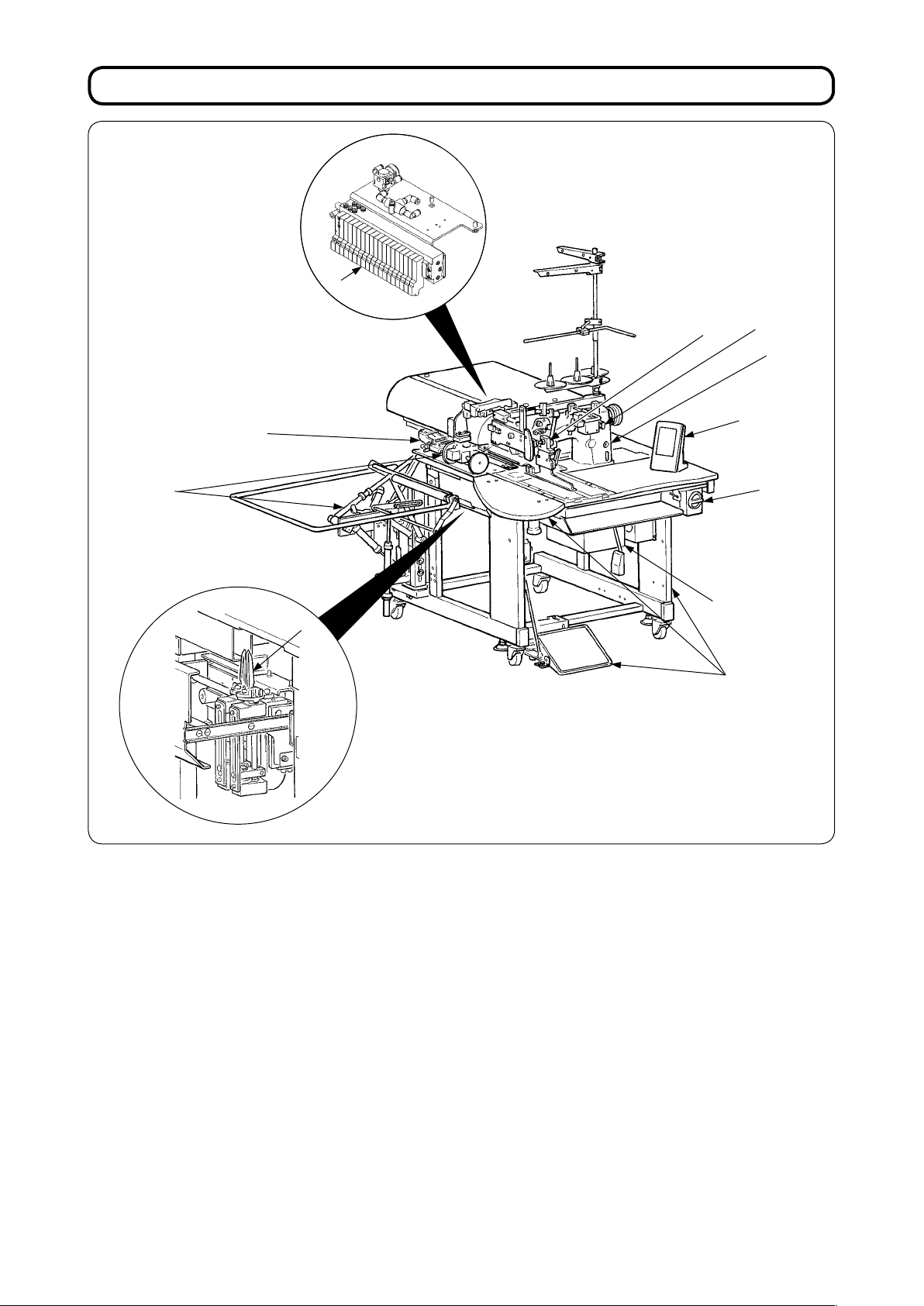
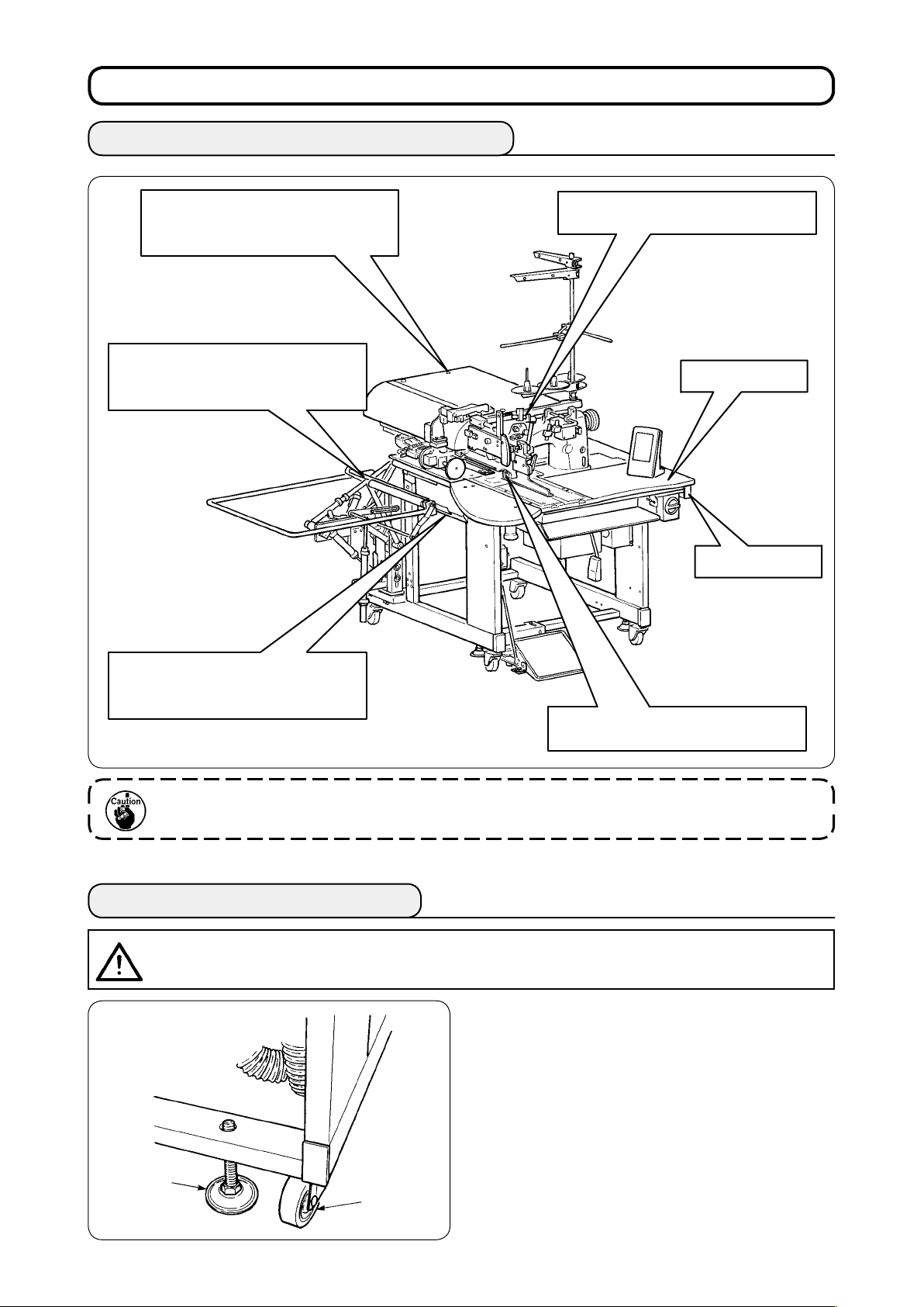
II. CONFIGURATION OF THE MACHINE
E
F
B
C
D
K
G
I
J
H
A
The APW-895 consists mainly of the following units.
Frame and structural components (Framesewing table, covers, foot switch, etc.)
A
Clamp foot unit and feed mechanism
B
Corner knife unit
C
Binder unit (Binder components and its driving components)
D
Pneumatic control unit (Pneumatic control devices and pipings)
E
Stacker unit (Optional)
F
Sewing machine head
G
Electric control unit (Control panel)
H
Operation panel
I
Power switch (Also used as the emergency stop switch)
J
Temporary stop switch
K
With this machine consisting of the aforementioned 11 units, you can do desired welting work simply by set-
ting materials (garment body, interlining piece, welting patch, etc.) in place and operating the switches on the
operation panel.
In addition, when temporary stop switch K is pressed during operation of the device, the device stops.
− 2 −
Page 7
III. SPECIFICATIONS
1. MECHANICAL SPECIFICATIONS
1 Sewing machine LH-895 model of 2-needle, lockstitch machine with a center knife
2 Sewing speed 3,000 sti/min (max.)
3 Stitch length Lockstitch : 2.0 to 3.4 mm (standard : 2.5 mm)
4 Types of welt Parallel double welt,
5 Pocket lip length
(Welt lenght)
6 Welting width
(Needle gauge)
7 Needles ORGAN DP X 17 #14 to #18 (standard #16)
Condensation stitch : 0.5 to 1.5 mm (standard : 1.0 mm)
Back tack stitch : 0.5 to 3.0 mm (standard : 2.0 mm)
Condensation/Back tack stitch selectable
parallel single welt
Standard type : Possible to set in increments of 1 mm within the range of min. 18 to
max. 220 mm
Note that the pocket length is min. 35 mm when using the corner knife.
(Min. 50 mm in case of 14 mm gauge or more, and min. 21 mm by adding a solenoid valve)
For the long and wide type : Possible to set in increments of 1 mm within the range of
Note that the pocket length is min. 70 mm when using the corner knife. (Min. 56 mm by adding a solenoid valve)
Possible to set max. 300 mm without entering corner knife.
8, 10, 12, 14, 16, 18 and 20 mm ( Long and wide type : 22, 24, 26, 28, 30 and 32 mm)
* However, for with dart stretcher, 8, 10, and 12 mm
For with zipper attachment, 16 mm, 18 mm, 20 mm
Each with ap or without ap
min. 18 to max. 250 mm
8 Thread Spun thread #60 (Recommended)
9 Hook Full rotary, vertical-axis, self-lubrication hook
10 Thread take-up lever Slide thread take-up lever
11 Needle bar stroke 33.3mm
12 Cloth feed mechanism Driven by stepping motor
13 Control By a micro-computer
14 Safety mechanism
15 Lubricating oil JUKI New Defrix Oil No. 1
16 Operating air pressure 0.5 MPa
17 Air consumption Approx. 40 Nℓ/min.
18 Dimensions of machine Width : 1,095 mm
19 Weight 238.5kg
20 Noise
Machine operation is automatically stopped if the cloth feed mechanism error detector,
the needle thread breakage detector or any of the various safety devices is actuated.
(1,580 mm - when including the stacker)
Length : 1,500 mm
Height :
- Equivalent continuous emission sound pressure level (LpA) at the workstation :
A-weighted value of 78.5 dB; (Includes KpA = 2.5 dB); according to ISO 10821- C.6.3
(Pattern : No.1, Jump feed speed of clamp foot : Max speed).
1,165 mm
-ISO 11204 GR2 at 3,000 sti/min for the sewing cycle, 4.5s ON.
(1,800 mm - when including the thread stand)
2. ELECTRICAL SPECIFICATIONS
The number of independent sewing patterns that can be
1
stored in memory
The number of alternate sewing patterns that can be
2
stored in memory
3
The number of cycles that can be stored in memory 20 (1 to 20)
4 Input power: Single phase/3-phase 200 to 240V 50/60 Hz (Optional 380V)
5 Power consumption 350VA
99 (1 to 99)
20 (1 to 20)
Voltage uctuation: Within + 10% of the rated voltage
− 3 −
Page 8
IV. INSTALLATION
1. REMOVING PACKING MATERIALS
Remove the upper cover and remove
the string and packing materials that
have xed the clamp foot.
Remove the string and packing
materials that have xed the clamp
bar stacker.
Remove the string that has xed the
binder unit.
Wooden table
Frame
Draw out the corner knife unit and
remove the string that has xed the
unit.
When lifting the machine, hold the frame without holding the wooden table.
2. SECURING THE MACHINE
CAUTION
To prevent a fatal accident, lower and x adjust bolts ❷ (4 places) located at the side of caster ❶ after
moving the machine to the level and stabilized place.
:
Cut and remove the clip band that
has xed the needle bar.
❷
❶
− 4 −
Page 9
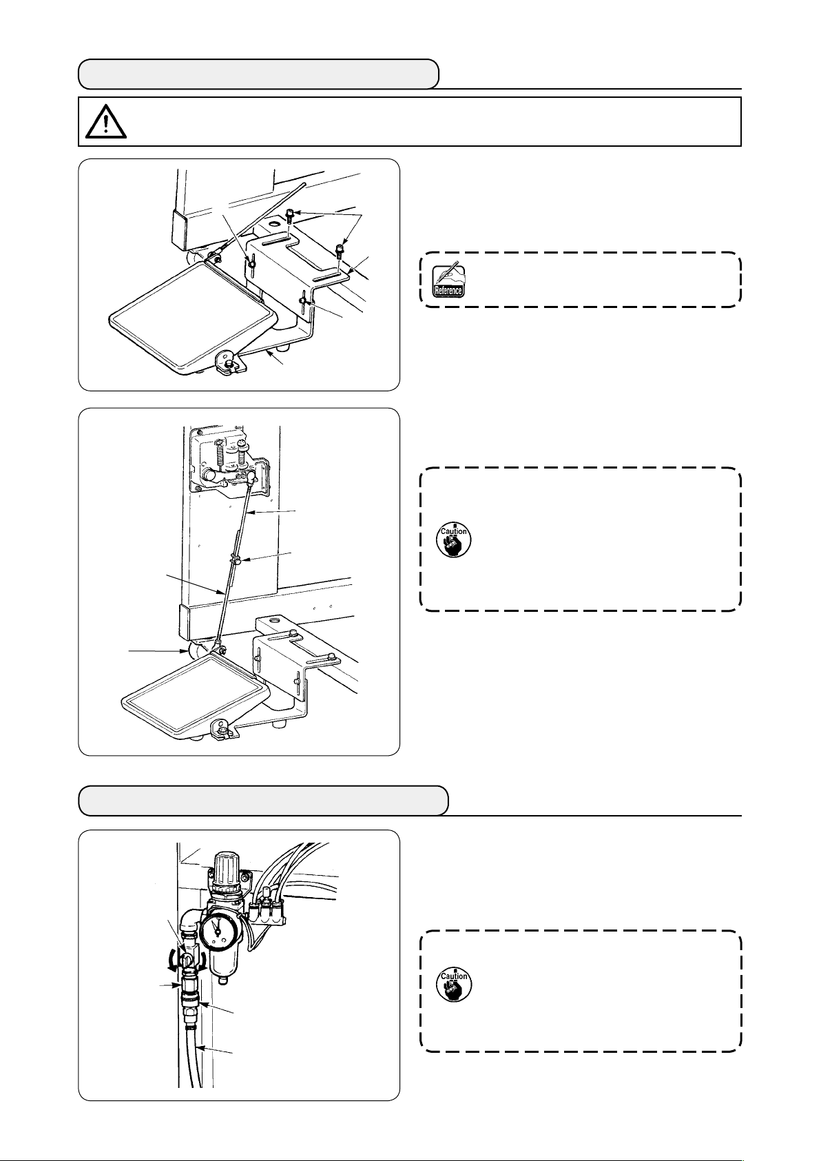
3. CONNECTING THE FOOT PEDAL
CAUTION
When installing the pedal, perform the work paying attention to the overhead table.
:
Install the pedal base to the machine frame with
①
screws ❷.
Connect pedal bases A and B with two screws
②
.
❶
Position of the pedal can be optionally
adjusted within the range of the slot.
Connect the connecting rods with xing screw
③
.
❸
1. When connecting, do not connect the
rods with connecting rod C on the
sensor side pulled downward,
2. Install so that connecting rod on the
pedal side D and the caster ❹ do not
interfere with each other within the
range of pedal operation.
D
❶
❷
B
❶
A
C
❸
❹
4. CONNECTING THE AIR COUPLER
Connect one end of air coupler A supplied with
the machine as an accessory to air hose ❷. Then
connect the other end to coupler ❸ on the main unit
side.
❶
❸
A
❷
• Connect coupler A to the main unit
with air cock ❶ closed, then carefully
open air cock ❶ to allow the com-
pressed air to be supplied.
• Make sure that the pressure gauge of
the regulator reads 0.5 MPa.
− 5 −
Page 10
5. CONNECTING THE POWER PLUG
CAUTION
To prevent possible accidents caused by leakage or dielectric strength, an appropriate power plug
shall be installed by a person who has an expert knowledge of electricity. Be sure to connect the power plug to the receptacle that is well grounded.
:
Connection of the power plug to the power depends on the specications of the product. Adjust the power
plug to the power specications to connect.
In case of the product of single-phase, 200 to 240V specications :
①
Connect the sky-blue and brown wires of the power cord to the power terminal (AC200 to 240V) and the
yellow/green wire to the ground (earth) terminal respectively.
In case of the product of 3-phase, 200 to 240V specications :
②
Connect the red, white and black wires of the power cord to the power terminal (AC200 to 240V) and
the yellow/green wire to the ground (earth) terminal respectively.
In case of the product with the optional high voltage transformer (with SA-128) :
③
Connect the black wires (3 pieces) of the power cord to the power terminal (AC380 to 415V) and the
yellow/green wire to the ground (earth) terminal respectively.
It is possible to connect to 380/400/415V by setting of the input tap of transformer (standard setting at
the time of delivery : 380V).
This product performs operation by the single-phase connection for 3-phasse 380/400/415V.
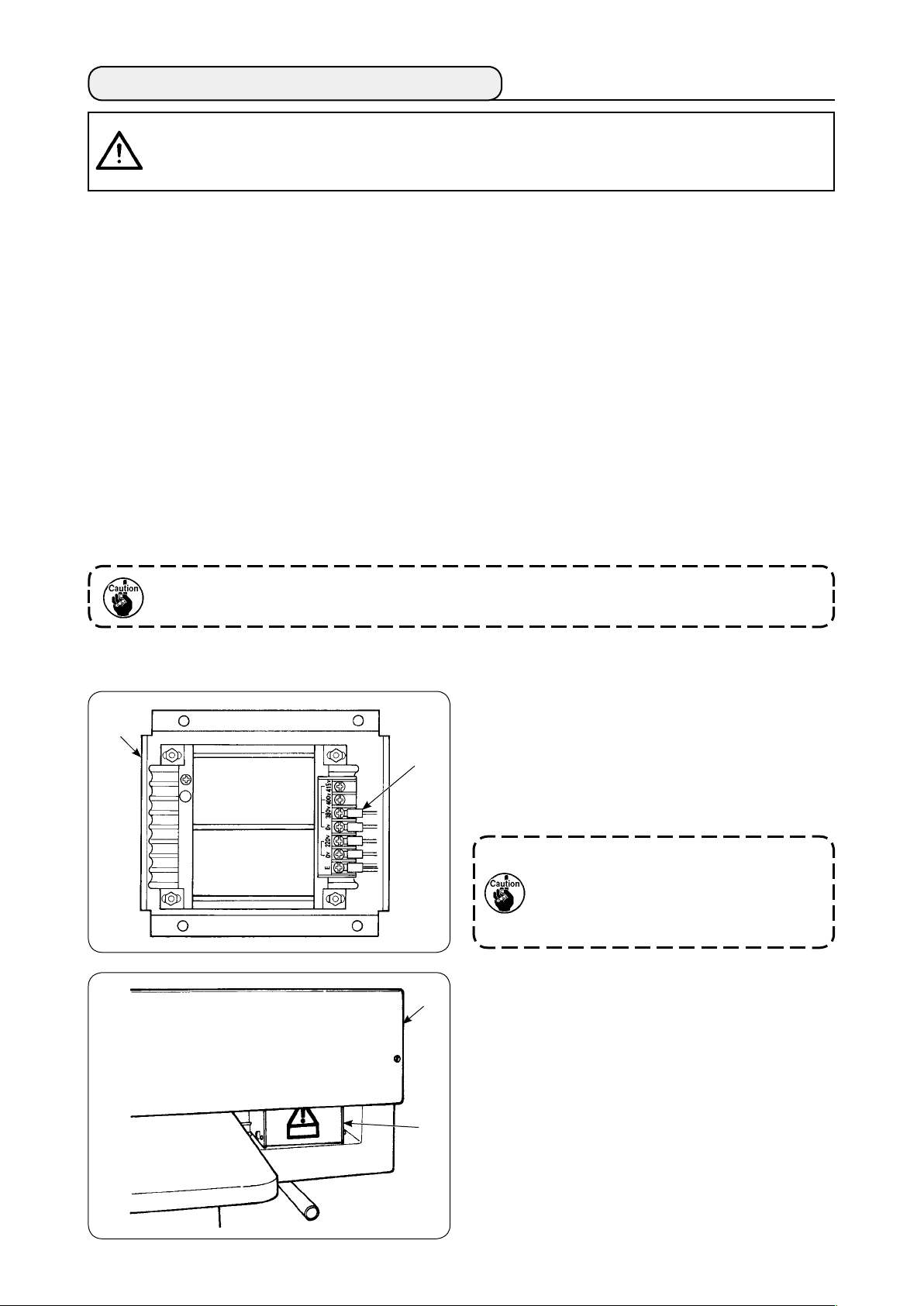
[ Caution when changing the power source of the high voltage optional transformer ]
When using high voltage optional transformer ❶ with
❶
the input voltage of 400V or 415V, it is necessary to
replace input power source cord ❷ of high voltage
❷
optional transformer ❶. Change power source input
cord ❷ (sky blue) that is connected to 380V to the
connection of 400V or 415V.
To prevent accidents, perform the work
after leaving the sewing machine alone
more than 4 minutes in the state that
the power switch is turned OFF and the
power cord is drawn out.
High voltage optional transformer ❶ is set on the
❸
rear side of the table.
When performing changeover of voltage, remove
transformer box ❹ after removing top cover ❸.
❹
− 6 −
Page 11
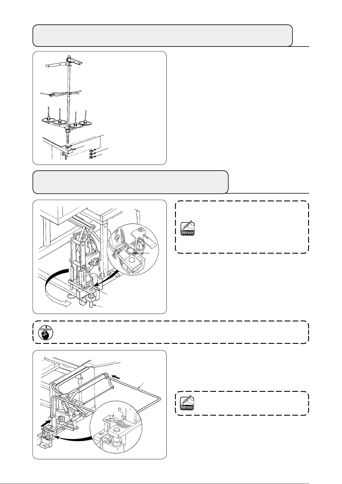
6. ASSEMBLING THE THREAD STAND AND ATTACHING IT TO THE MACHINE
Putting nut and washer between main unit frame ❶
and x the thread stand as illustrated in the left-hand
gure.
Washer
❶
Spring washer
Nut
7. INSTALLING SP-46 (CLAMP BAR STACKER)
(OPTIONAL PART NO. : 40058952)
Clamp bar stacker is delivered in the
state that it is xed in the frame at the
time of delivery with the clamp bar
stacker mounted. It is necessary to
change the installing position to the nor-
mal using position.
❶
B
A
Remove stacker xing plate ❶.
①
Turn the whole stacker in the direction of the
②
arrow and take it out from inside of the frame.
Change stacker turning shaft A section to
③
stacker base hole B.
C
At this time, take care to prevent the stacker cord, the air piping, etc. from being caught.
Lock the whole stacker with hinge ❷.
④
Enter safety bar ❸ from C and D directions
⑤
and x it at the position where is almost parallel
to the oor.
At this time, conrm that air is being
supplied.
❷
D
❸
− 7 −
Page 12
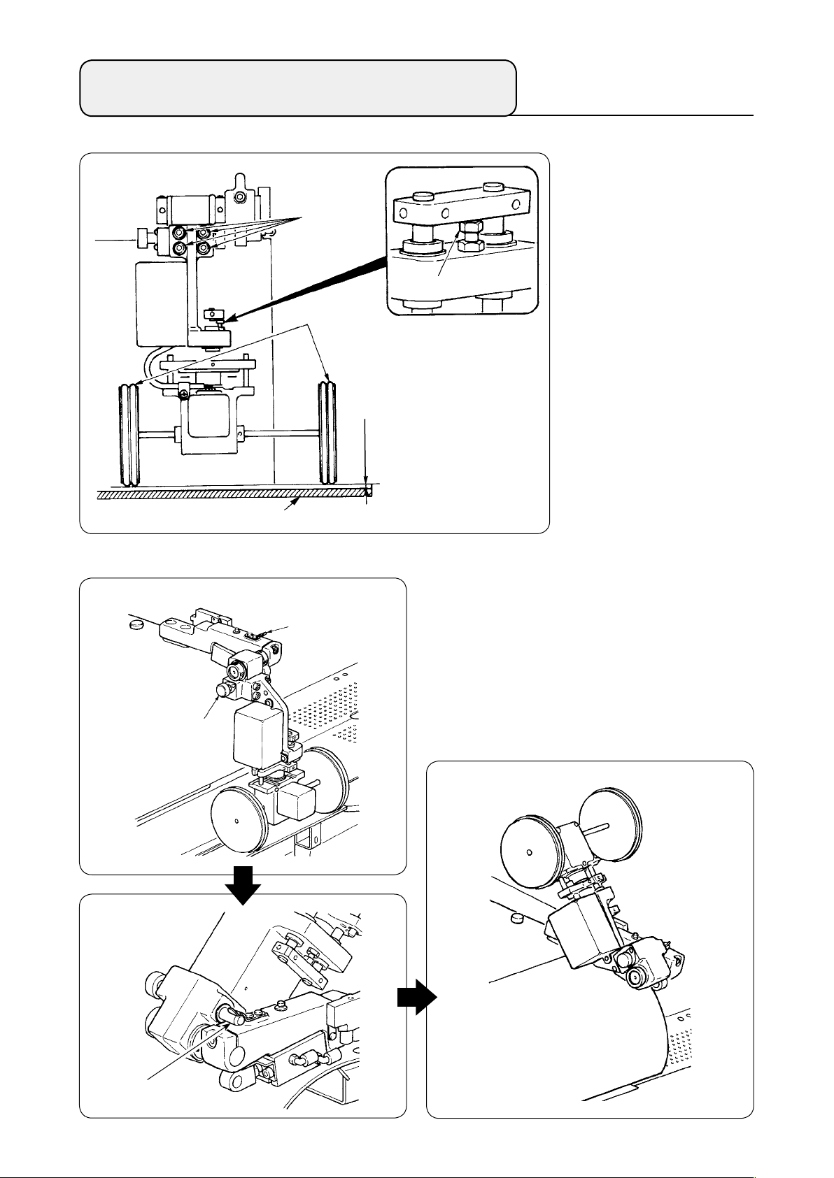
8. INSTALLING SP-47 (ROLLER STACKER)
(OPTIONAL PART NO. : 40058953)
(1) Adjusting the position
❷
❺
Conrming parallelism
①
Make sure that stacker
table ❹ and rubber roller
are installed parallel
❸
with each other.
If not, loosen four set-
screws ❷ to adjust.
(2) Maintenance
(Working state)
❶
❹
❷
❸
0.5mm
Conrming the clearance
②
Make sure that the clear-
ance between stacker
table ❹ and rubber roller
is approximately 0.5
❸
mm.
If it is not approximately
0.5 mm, loosen nut ❺ to
adjust.
When the roller stacker is not used or adjusting the
corner knife, the roller stacker can be turned upward
with the procedure below.
Pull release lever ❶. Lift up the roller section to
thrust pin ❸ into xing spring ❷, then bring them
into locked state (see Fig. 1). This puts the sewing
machine in standby state.
Fig. 1
(Waiting state)
❸
− 8 −
Page 13
9. REMOVING THE HEAD FIXING PLATE
Remove xing screws ❷ of head xing plate ❶.
❷
❶
10. INSTALLING THE SUB-TABLE
Install the sub-table with four screws ❶ as shown in
the gure.
Be sure to x the machine and the frame
when performing re-transportation.
At this time, x the sub-table so as to be
ush with the main table.
❶
❶
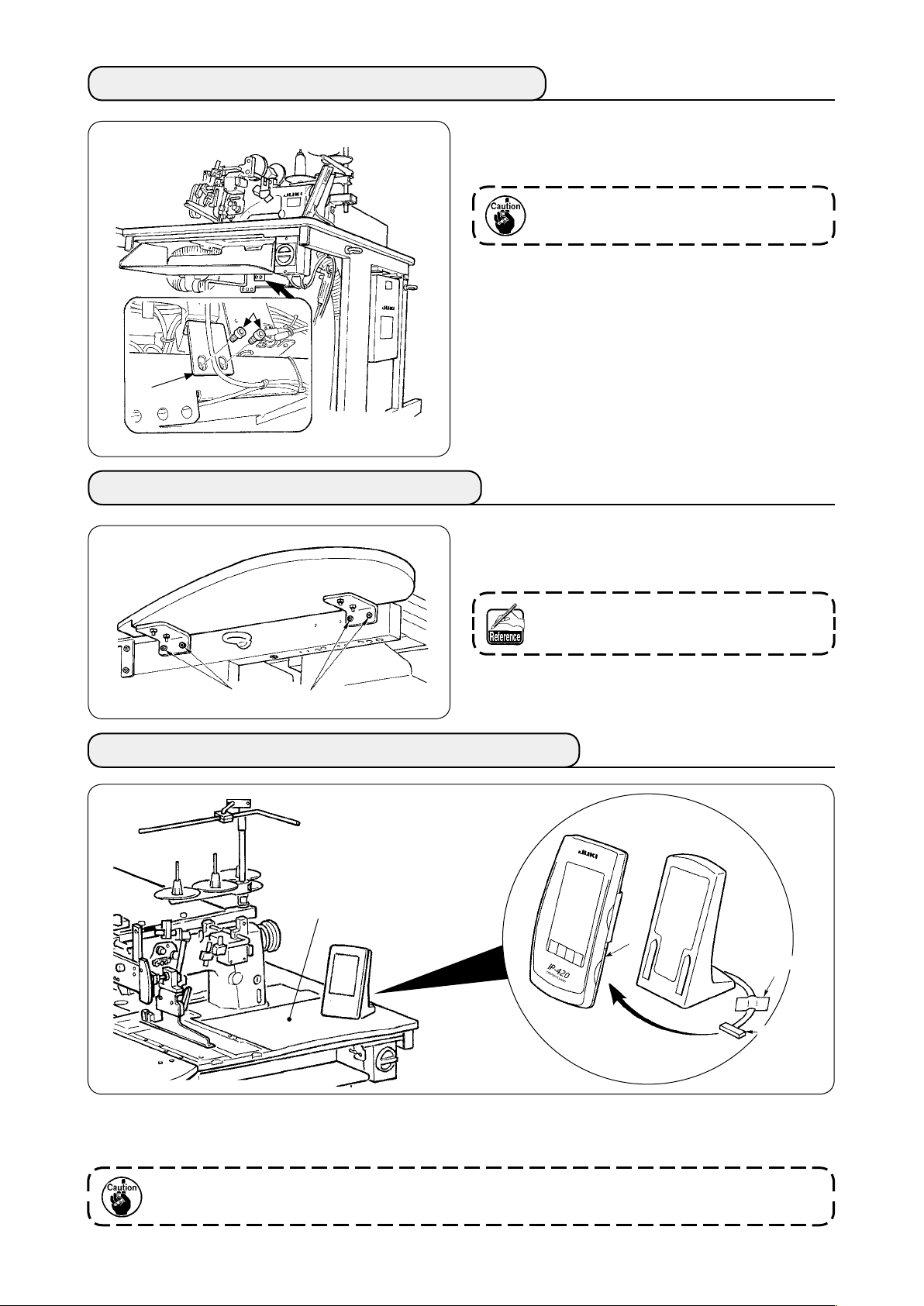
11. INSTALLING OPERATION PANEL IP-420
B
C
Tape
Connector
As shown in the gure above, open the lid on the right-hand section C of IP-420 and connect the connector
which is xed with tape to the right-hand top surface B of the table.
To prevent malfunction due to static electricity, install operation panel IP-420 on the panel base
to use and do not change the position of the panel base.
− 9 −
Page 14
12. LUBRICATING THE OIL TANK
CAUTION
1. To prevent accidents caused by abrupt start of the sewing machine, do not connect the power
plug until lubrication has been completed.
2. To prevent inammation or rash, immediately wash the part when oil has stuck to your eyes or
body.
3. If oil has been swallowed, diarrhea or vomiting may occur. Put oil to the place where children can-
not reach.
:
Fill the oil tank with the oil for hook lubrication before
operating the sewing machine.
Remove oil cap ❶ and ll the oil tank with
①
JUKI MACHINE OIL No. 1 (Part No. : MD-
FRX1600C0) using the oiler supplied with the
❶
Upper
engraved
marker line
❸
machine as accessories.
To prevent entering of dust, be sure to
attach the cap for use.
❷
Fill the oil tank with the oil until the top end of
Lower
engraved
marker line
②
oil amount indicating rod ❸ comes between
the upper engraved marker line and the lower
engraved marker line of oil amount indicating
window ❷.
When oil amount is excessively large, oil leaks
from the air hole or adequate lubrication cannot
be performed. So, be careful.
When operating the sewing machine and the top
A
A
③
of oil amount indicating rod ❸ has lowered up to
oil amount indicating window ❷, start lubricat-
ing.
− 10 −
• At the time of initial lling, ll the oil
tank with oil of 200cc as the standard
and conrm that the oil amount indicating rod is working.
• When operating a newly installed
machine or a machine which has not
been used for a relatively long period
of time, make the machine run at 2,000
sti/min or less for the purpose of
break-in. In addition, use the machine
after applying oil to races A of the
right/left hooks.
• For the oil for hook, purchase JUKI
MACHINE OIL No. 1 (Part No. : MDFRX1600C0).
• Be sure to ll the oil tank with clean
oil.
Page 15
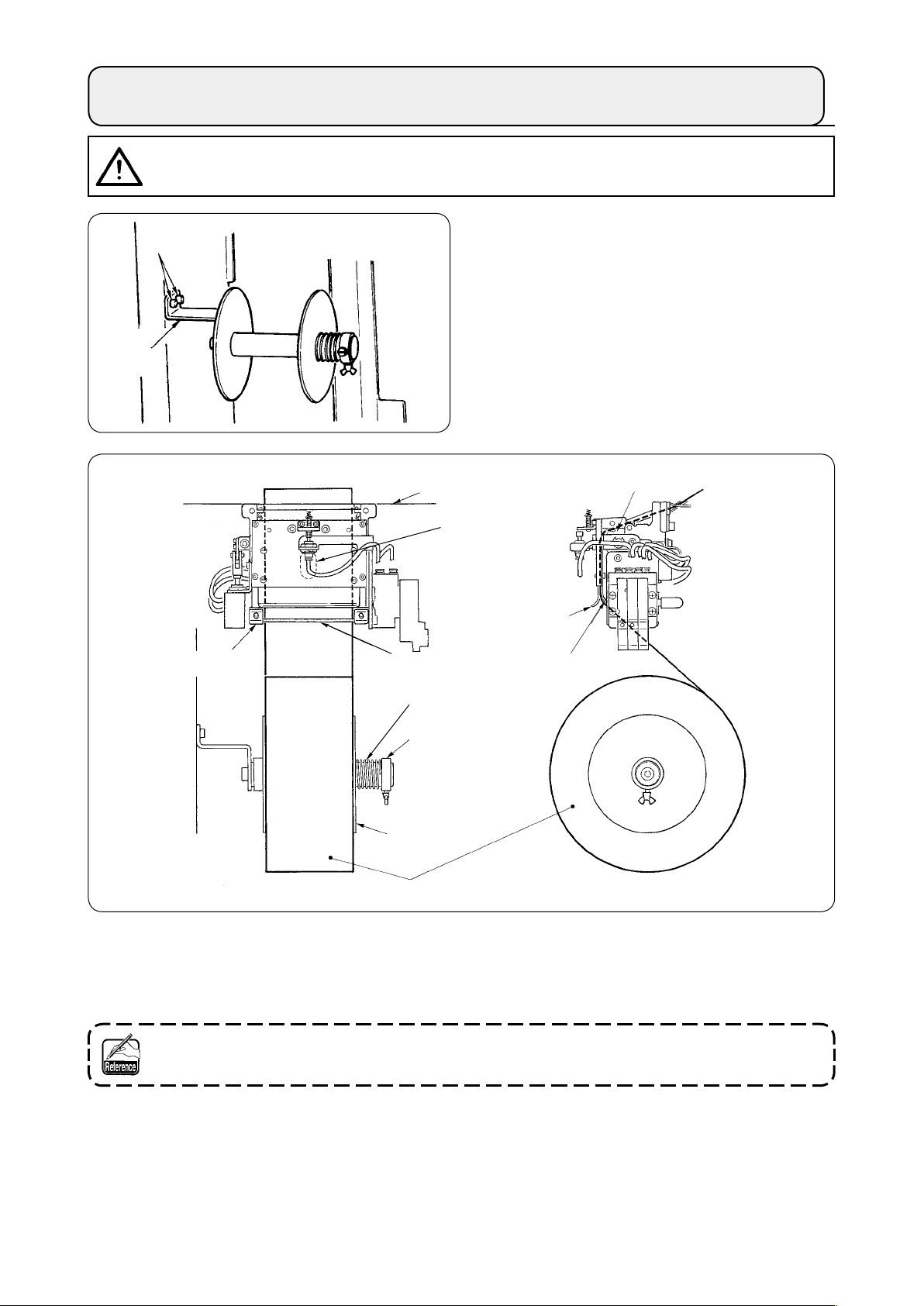
13. INSTALLING SA-120 (INTERLINING SUPPLYING DEVICE) (OPTIONAL PART NO. : 40045772)
CAUTION
Turn OFF the power before starting the work so as to prevent accidents caused by abrupt start of the
sewing machine.
:
* It cannot be used for the long and wide type.
❷
Fix interlining installing plate ❶ to the machine
①
frame with two screws ❷.
❶
Sewing table
Notch
Roller
Guide A
Guide plate
Set interlining as shown in the gure above.
②
Guide B
Spring
Set collar
Side plate
Interlining
Guide B
The roll core that can be used is 40 to 70 mm wide and 200 mm in roller diameter (max.).
Pass the interlining between guide B and guide A and roller, and route it up above the table.
③
Feed the interlining up to the roller section using the notch of the guide plate.
Adjust the lateral position of two guides, two guide pins and side plate (on the right) to allow the interlin-
④
ing to be fed straight up above the sewing table.
Position the set collar on the left-hand side to allow the side plate to lightly hold the interlining by spring.
⑤
Then x the set collar there.
− 11 −
Page 16
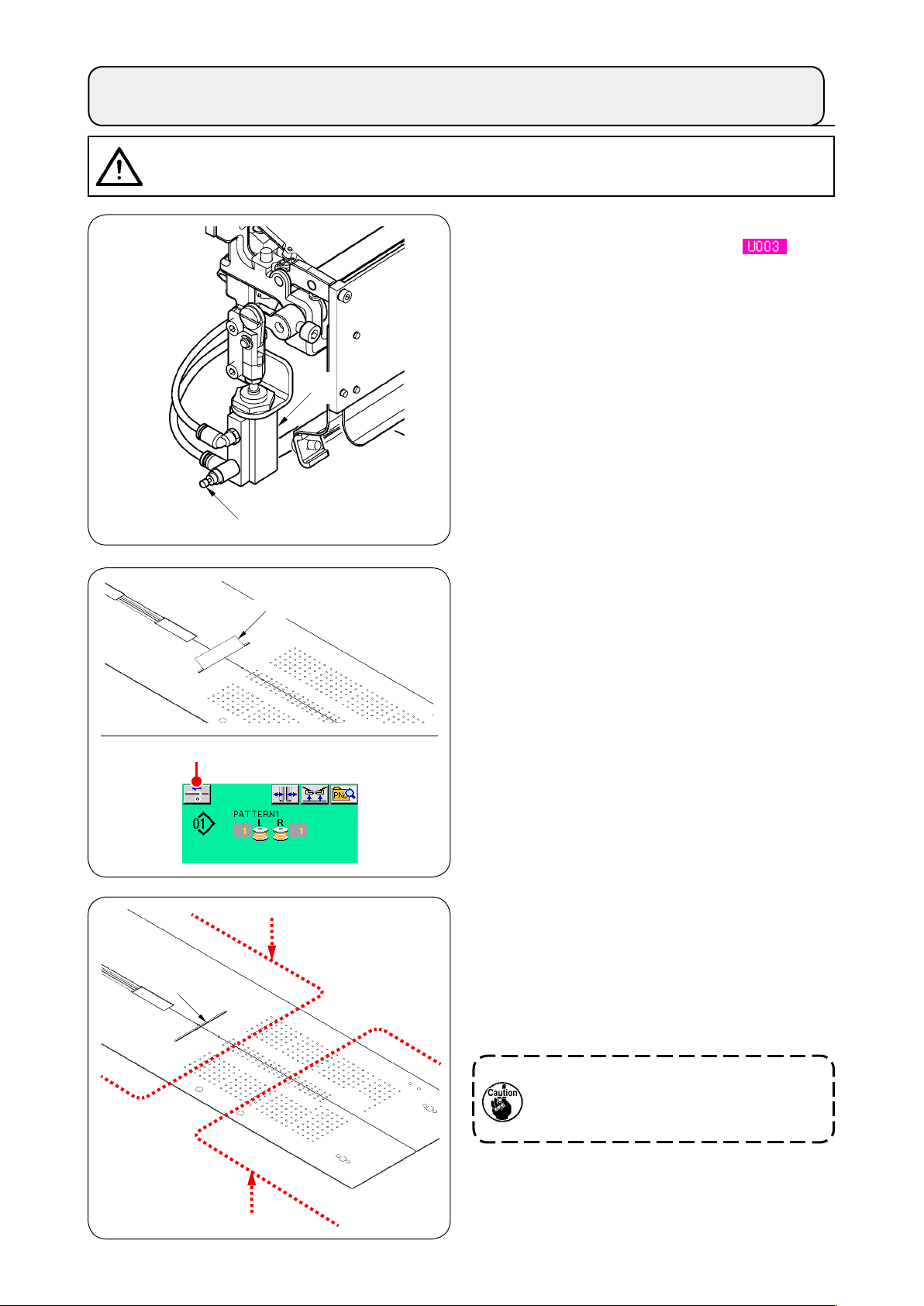
14. ADJUSTMENT OF SA-120 (INTERLINING SUPPLYING DEVICE) (OPTIONAL PART NO. : 40045772)
CAUTION
Turn OFF the power before starting the work so as to prevent accidents caused by abrupt start of the
sewing machine.
:
❷
❸
❶
Adjustment of the interlining feeding amount
①
is performed with memory switch (
However, perform further ne adjustment with
the speed controller ❷ of the interlining feeding
cylinder ❶.
(When tightening the speed controller
amount is decreased and when loosening it, the
amount is increased.)
When a new interlining
②
interlining supply button ❹, perform feeding
of the trial sewing several times and use the
device after conrming the feeding amount and
the parallel feeding of the interlining.
is mounted, press
❸
❷
).
, the
❻
❹
❺
(Caution when operating)
When using the interlining supplying device with
rear reference ❺, the interlining at the sewing
start remains long since it is away from interlin-
ing outlet ❻. So, use the device with front refer-
ence ❼.
For handling the sewing tables, refer to
"V-2.(2) Cautions to be taken when the
sewing tables are removed" p. 16
❼
− 12 −
Page 17
V. PREPARATION OF THE SEWING MACHINE
1. HOW TO OPERATE THE SEWING MACHINE HEAD
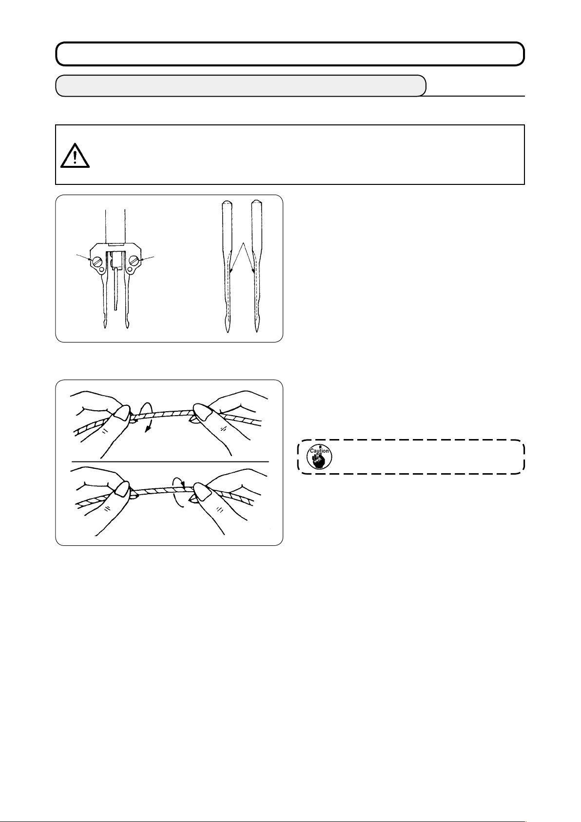
(1) How to attach the needles
CAUTION
• Turn OFF the power before starting the work so as to prevents accidents caused by abrupt start of
the sewing machine.
• When replacing the needle, be careful not to allow your ngers to touch the blade section of the
center knife.
❷
(2) Thread used
:
Needles used are DP X 17 #14 to #18 (standard
#16). Use the specied needle.
❶
❷
Insert left- and right-hand sides needles as far as
they will go pointing their long grooves ❶ at each
other and tighten needle clamp screws ❷.
• Use the left hand twist thread for the needle
thread.
• Either twist thread will do for the bobbin thread.
Right hand twist thread
Left hand twist thread
Use a new thread which is uniformly
twisted.
− 13 −
Page 18
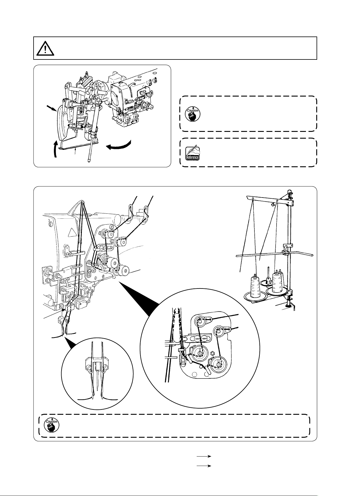
(3) How to pass the needle thread
CAUTION
Turn OFF the power before starting the work so as to prevent accidents caused by abrupt start of the
sewing machine.
:
Lift binder ❶ in the direction A, Hold section B
①
by hand and turn the whole binder in the direc-
tion C.
B
A
❶
Then pass needle thread in the order as shown in the gure below.
②
C
B
A
Be sure to press section B since welt-
ing width may become improper when
the binder is pressed and turned in the
direction C.
Binder is locked with the ball plunger.
Rather strongly turn the binder in the
direction C to release the lock.
C
A
B
A
A
B
A B
A
Periodically replace thread guide felt C. Sewing trouble due to rough motion of thread
during sewing can be prevented.
B
B
Pass the needle thread in the illustrated order.
Left-hand side needle thread toward the sewing machine
Right-hand side needle thread toward the sewing machine
− 14 −
A
B
Page 19
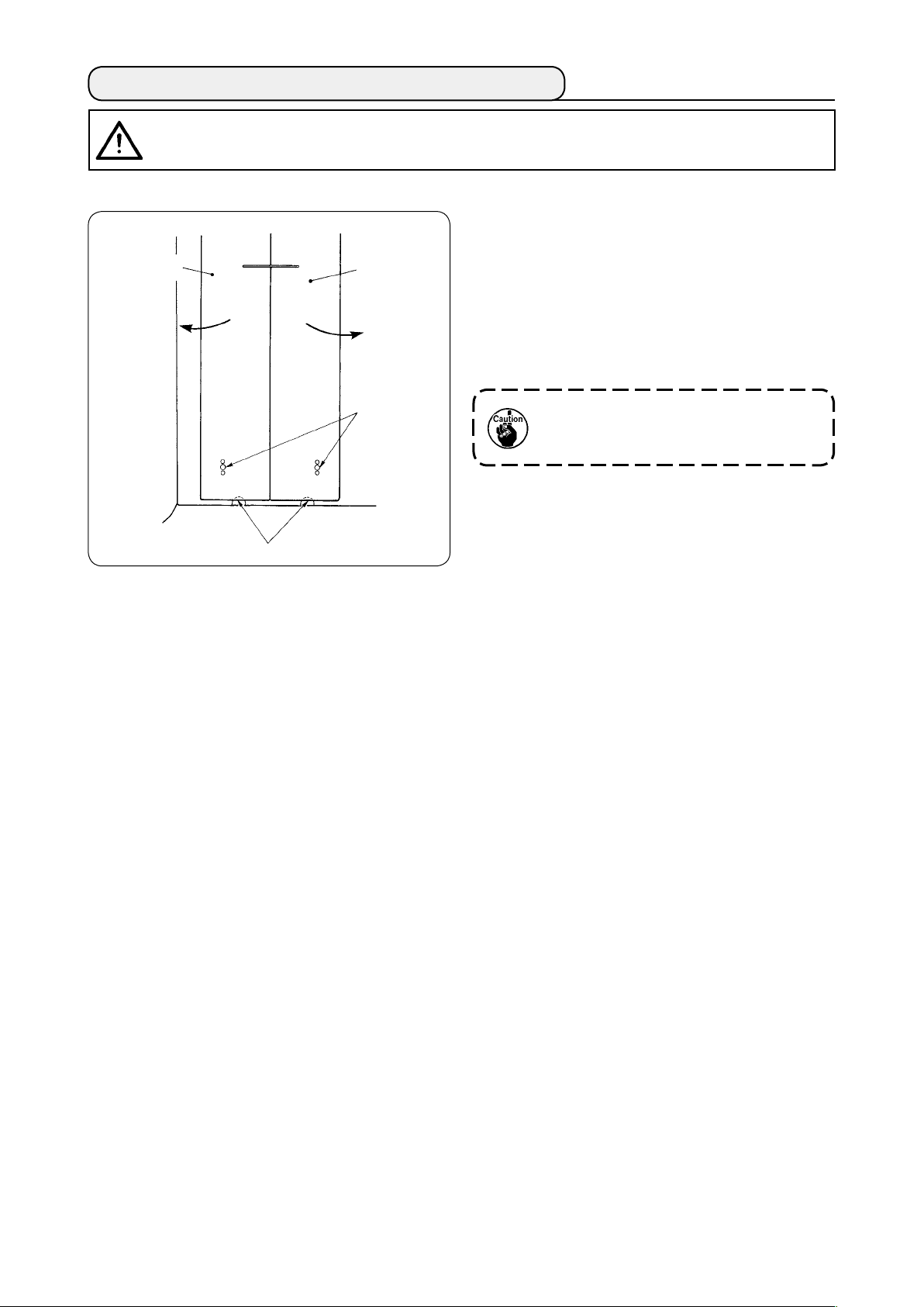
2. HOW TO REMOVE THE SEWING TABLE
CAUTION
Turn OFF the power before starting the work so as to prevent accidents caused by abrupt start of the
sewing machine.
:
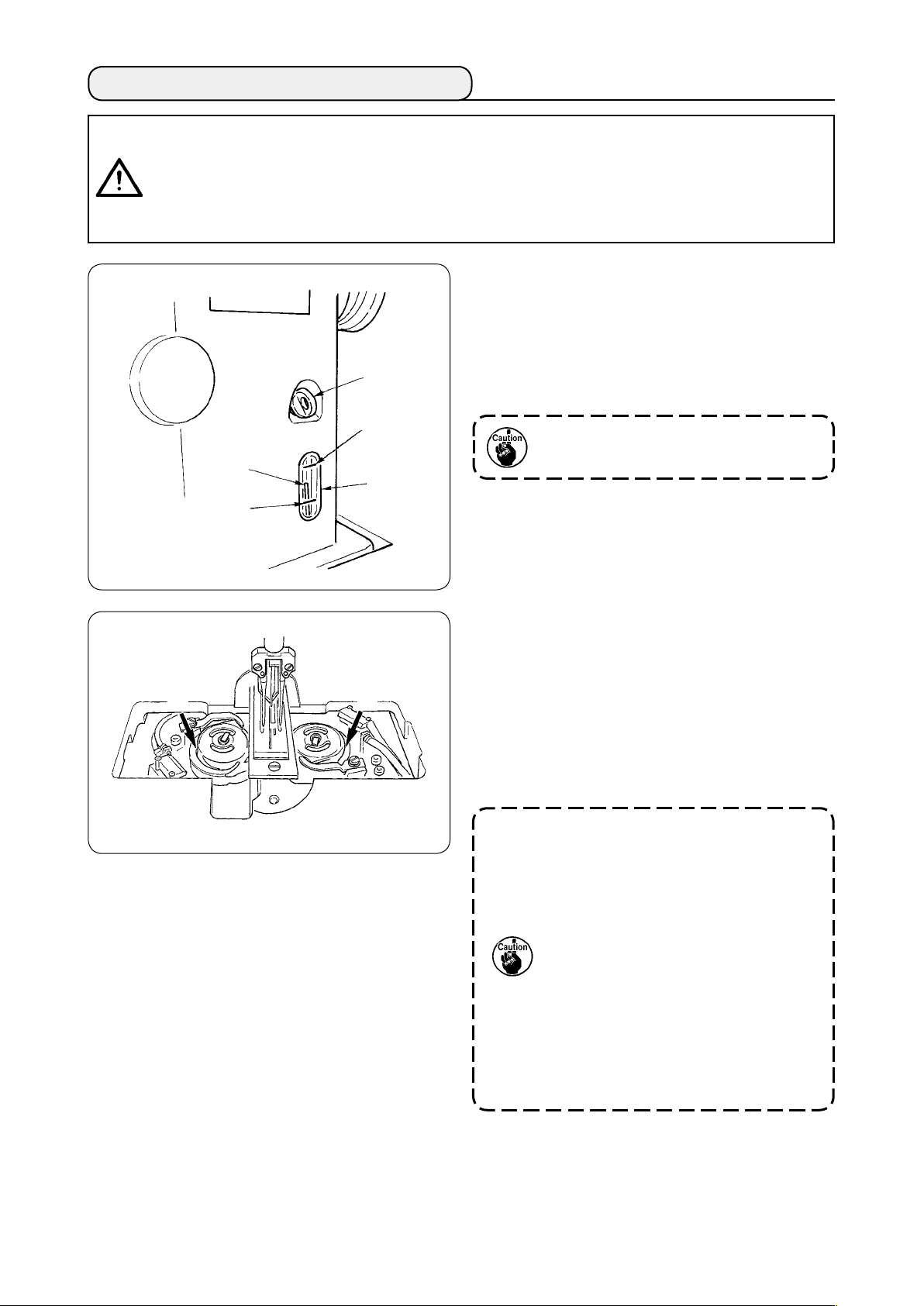
(1) When replacing the bobbin thread
❷
A
❶
Pin
Move the clamp foot to the rear end of its stroke.
①
Insert your ngers into notches A in the bottom
②
of right- and left-hand sewing tables ❶ and ❷,
and push up the sewing tables.
Move the tables in the direction of the arrow
③
keeping the above state, and you can see the
bobbin case.
At this time, move the sewing tables
so as not to allow the sewing tables to
come in contact with the needles.
After replacing the bobbin thread, return
④
the sewing tables in place by following the
above-mentioned steps of procedure in the
reverse order. Now, rmly set the sewing tables
on the throat plates and the pins.
− 15 −
Page 20
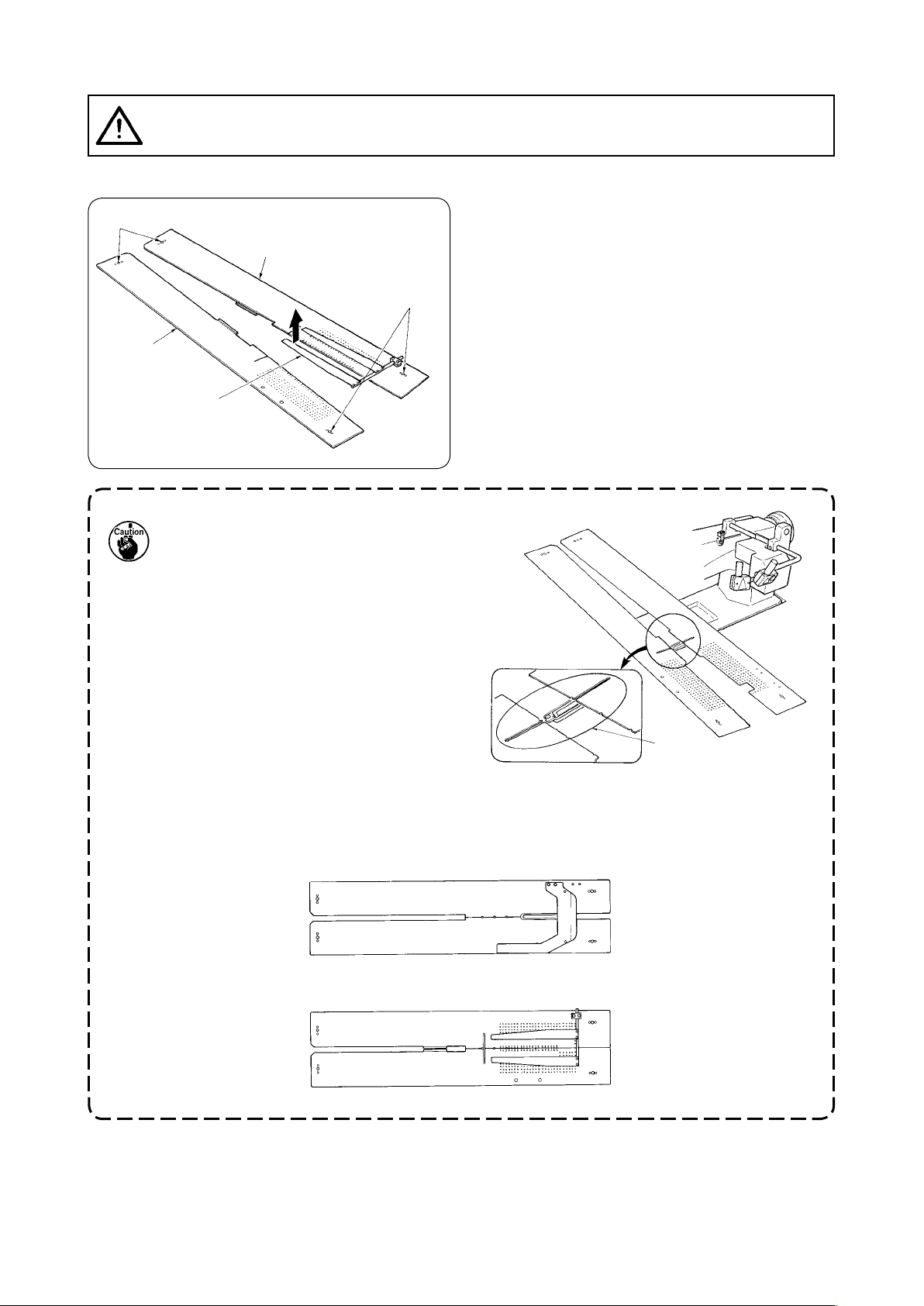
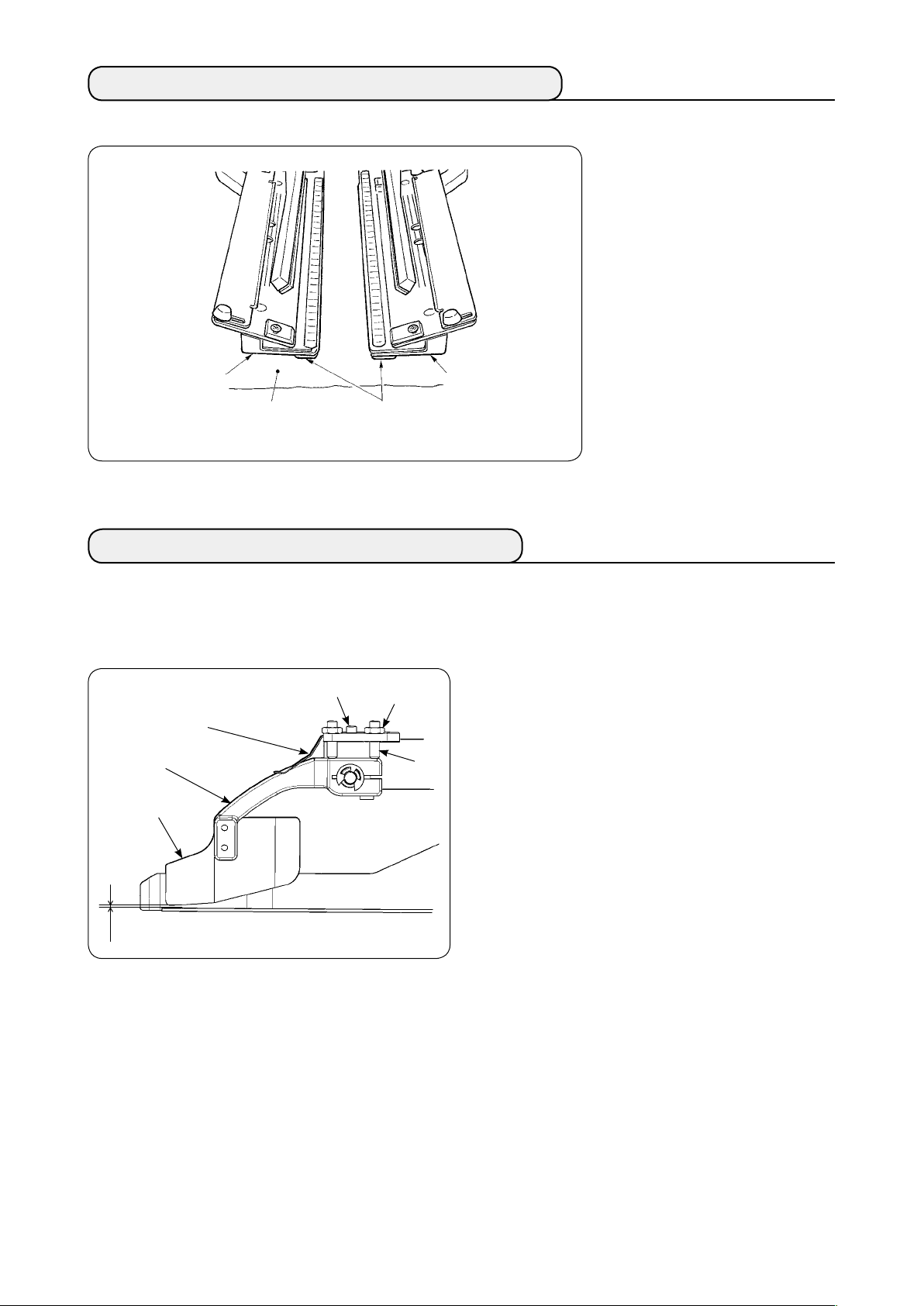
(2) Cautions to be taken when the sewing tables are removed
CAUTION
Turn OFF the power before starting the work so as to prevent accidents caused by abrupt start of the
sewing machine.
:
When you remove the sewing tables, be sure to accurately set them by following the points below.
Securely t the pins, rear (left) (right) over the
Pins, rear
❶
①
pin holes.
Securely t pin holes, front (left) (right) over the
②
pins.
Pin holes, front
❷
Plate spring
1. In case of the machine provided with
SA-120 (automatic interlining supply-
ing device), return the sewing tables
to their home positions while lifting
the sewing tables so that the plate
spring section is not bent.
Outlet of interlining
supply
2. In case of removing the sewing tables with the types below, take care not to bend pocket bag
clamping device and interlining clamping device.
Pocket bag clamping device (standard)
①
Pocket bag clamping device (for interlining supply)
②
− 16 −
Page 21
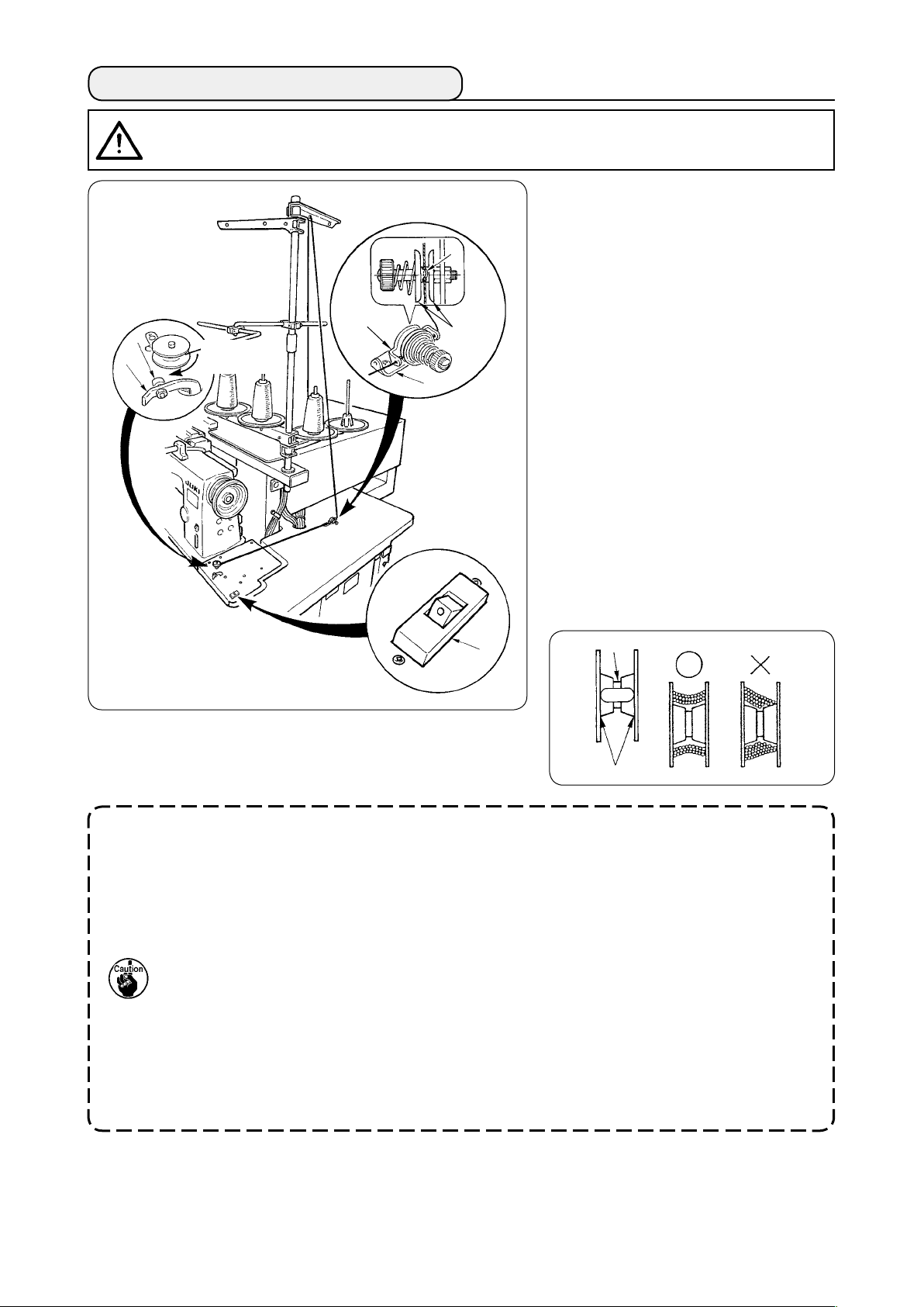
3. HOW TO WIND THE BOBBINS
CAUTION
To prevent damage, avoid contact with bobbins while the machine is in operation.
:
Put bobbin into the thread winder
①
shaft until it will go no further.
Pass thread through thread guide
②
❹
plate ❽, open thread tension disk
and put the thread into the slit of
❼
thread tension rod ❹.
❶
❷
❽
Direction of
rotation
❸
❼
Pass thread in the order as shown in
③
the gure, and wind the thread onto
bobbin by four or ve turns. (The
direction of the arrow corresponds to
the direction of rotation of the bob-
bin.)
Press bobbin thread guide ❶ and
④
the bobbin rotates.
The thread winder will automatically
⑤
stop as soon as it has wound up the
bobbin to a predetermined amount.
❾
1. If you want to wind a bobbin, start winding it from recess ❺ as illustrated in the gure above. If
you start to wind a bobbin from portion ❻, the detection of run-out of bobbin thread will fail to
be performed normally.
2. To ensure the appropriate remaining amount of bobbin thread, it is important to wind the bobbin
uniformly. Be sure to check that the bobbin is uniformly wound particularly at the start of bob-
bin winding.
If the bobbin fails to be uniformly wound with thread, properly adjust the lateral position of ten-
sion post socket ❸.
3. It is most suitable to wind the bobbin with thread to approximately 80% of the outer diameter of
the bobbin. The winding amount can be adjusted with winding amount adjustment screw ❷.
4. Do not press lever ❶ except when winding bobbin thread. Motor continues to run and trouble
will be caused.
5. When abnormalities such as overload of the thread winding motor, etc. are delected, thermal
switch ❾ is shut off. When thermal switch is shut off, turn ON thermal switch ❾ again after
turning OFF it to return.
❺
❻
− 17 −
Page 22
4. HOW TO THREAD THE BOBBIN CASE
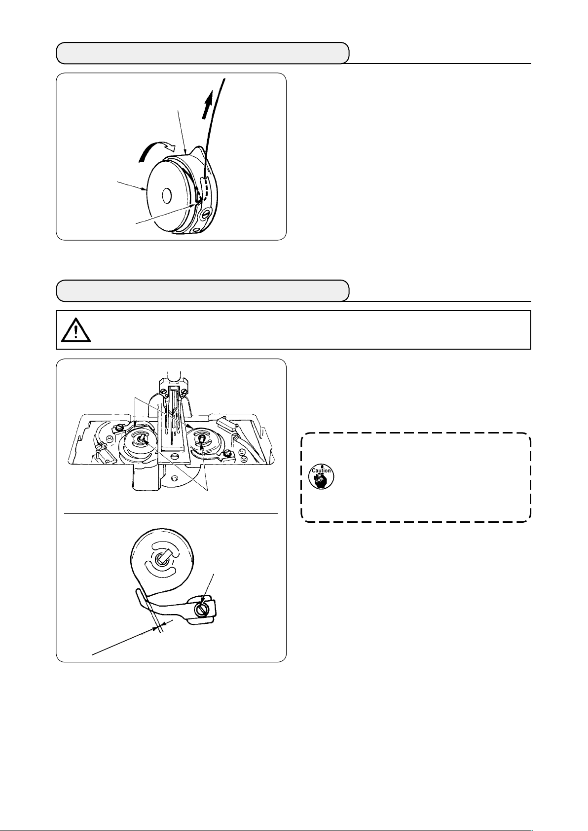
Hold in hand a bobbin in the way that it spins
①
clockwise and put it into the bobbin case.
Bobbin case
Pass the thread through slot ❶ in the bobbin
②
case.
Pull the thread to pass it under the tension
③
spring.
Bobbin
❶
5. HOW TO INSTALL THE BOBBIN CASE
CAUTION
Turn OFF the power before starting the work so as to prevent accident caused by abrupt start of the
sewing machine.
:
Raise hook levers ❶ and take out the bobbin
①
cases together with the bobbins.
❷
When tting, t the bobbin cases into the hook
②
driving shaft and tilt levers ❶.
When bobbin cases, left and right, ❷ are
replaced, make sure that the clearance
between the opener which is extremely
❶
❸
receded and the bobbin case is 0.2 to 0.3
mm. If the clearance is not 0.2 to 0.3 mm,
loosen setscrew ❸ and adjust it.
0.2 to 0.3mm
− 18 −
Page 23
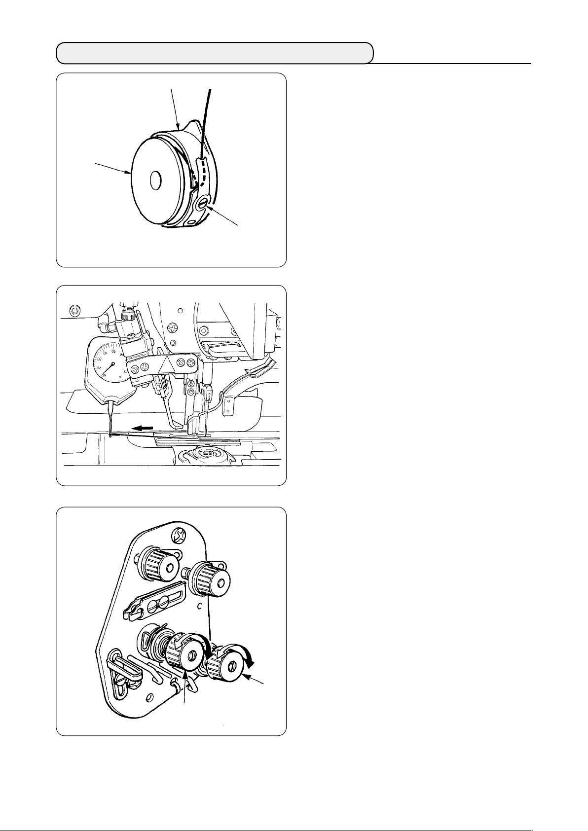
6. HOW TO ADJUST THE THREAD TENSION
Adjusting bobbin thread tension
Bobbin case
Bobbin
Bobbin thread
tension adjustment
screw
①
Turn bobbin thread tension adjustment screw
clockwise to increase the bobbin thread tension
or turn the screw counterclockwise to decrease
it.
As shown in the left-hand gure, standard
bobbin thread tension is 0.25 to 0.35N when
measuring with the tension gauge.
❷
❶
Adjusting needle thread tension
②
First, adjust the right- and left-hands bobbin
thread tension.
Then in accordance with the bobbin thread
tension obtained, adjust the right- and left-hand
sides needle threads tension appropriately by
turning thread tension adjustments nuts ❶ and
respectively. Turning the nuts clockwise will
❷
increase the thread tension or turning them
counterclockwise to decrease it.
− 19 −
Page 24
7. SETTING THE MATERIAL TO BE SEWN
(1) Setting a garment body
Garment body
clamp (left)
Garment body
Garment body
clamp rubber
Garment body
clamp (right)
Use a garment body that is larger
than the garment body clamp rub-
ber piece adhered under the right
and left garment body clamps.
If a garment body of which size
is smaller than the garment body
clamp rubber piece, the rubber
piece can come off or the machine
can malfunction.
If it is necessary to use a small
material, mount a shim type gauge
(optional) on the machine.
8. ADJUSTING THE MATERIAL GUIDE
Material guide functions to stabilize the welt patch at the edge of the machine needle.
Adjust the height and the presser pressure of material guide ❶ in accordance with the thickness of material.
The height of material guide can be adjusted by
①
loosening nut ❷ and screw ❸.
(Clearance between material guide and welt
patch scale has been adjusted to 0.5 to 1.0 mm
at the time of delivery.)
Presser pressure can be adjusted with spring
②
pressure adjust screw ❹.
(Adjust the pressure so that there is no exces-
sive resistance when the material passes.)
Material guide
spring
Material guide arm
❶
0.5 to 1.0 mm
❹
❷
❸
− 20 −
Page 25
VI. HOW TO USE THE OPERATION PANEL
1. PREFACE
1) To use the data for APW895/896 (EPD data) on APW-895
To use the EPD data on the APW-895, read the data into the IP-420.
Insert the relevant medium into the IP-420. Select pattern number xxx from EPD data.
2) Folder structure of the media
Store each le in the directories below of the media.
Media drive
Data that are not stored in the directories above cannot be read. So, be careful.
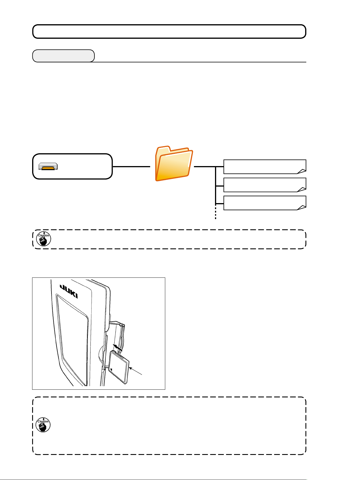
3) CompactFlash (TM)
Inserting the CompactFlash (TM)
■
Media
APW895
1) Turn the label side of the CompactFlash(TM) to
this side (place the notch of the edge to the rear.
) and insert the part that has a small hole into
the panel.
2) After completion of setting of the media, close
the cover. By closing the cover, it is possible to
access. If the media and the cover come in con-
tact with each other and the cover is not closed,
check the following matters.
• Check that the media is securely pressed
until it goes no further.
• Check that the inserting direction of the me-
dia is proper.
APW××× .EPD
APW××× .EPD
APW××× .EPD
1. When the inserting direction is wrong, panel or media may be damaged.
2. Do not insert any item other than the CompactFlash (TM).
3. The media slot in the IP-420 accommodates to the CompactFlash (TM) of 2 GB or less.
4. The media slot in the IP-420 supports the FAT16 which is the format of the CompactFlash (TM).
FAT32 is not supported.
5. Be sure to use the CompactFlash (TM) which is formatted with IP-420. For the formatting proce-
dure of the CompactFlash (TM), see"VI-17. PERFORMING FORMATTING OF THE MEDIA" p. 92
− 21 −
Page 26

Removing the CompactFlash (TM)
■
1) Hold the panel by hand, open the cover, and
press the media ❷ removing lever ❶. The me-
dia is eject.
4) USB port
Inserting a device into the USB port
■
❷
❶
When the lever ❶ is strongly pressed,
the media ❷ may be broken by protrud-
ing and falling.
2) When the media ❷ is drawn out as it is, remov-
ing is completed.
Slide the top cover and insert the USB device into
the USB port. Then, copy data to be used from the
USB device onto the main body.
After completion of copying the data, remove the
USB device.
Disconnecting a device from the USB port
■
Cautions when using the media
• Do not wet or touch it with wet hands. Fire or electric shock will be caused.
• Do not bend, or apply strong force or shock to it.
• Never perform disassembling or remodeling of it.
• Do not put the metal to the contact part of it. Data may be disappeared.
• Avoid storing or using it in the places below.
Place of high temperature or humidity / Place of dew condensation /
Place with much dust / Place where static electricity or electrical noise is likely to occur
Remove the USB device. Put the cover back in
place.
− 22 −
Page 27

Precautions to be taken when handling USB devices
①
• Do not leave the USB device or USB cable connected to the USB port while the sewing machine is in
operation. The machine vibration can damage the port section resulting in loss of data stored on the
USB device or breakage of the USB device or sewing machine.
• Do not insert/remove a USB device during reading/writing a program or sewing data.
It may cause data breakage or malfunction.
• When the storage space of a USB device is partitioned, only one partition is accessible.
• Some type of the USB device may not be properly recognized by this sewing machine.
• JUKI does not compensate for loss of data stored on the USB device caused by using it with this sewing
machine.
• When the panel displays the communication screen or pattern data list, the USB drive is not recognized
even if you insert a medium into the slot.
• For USB devices and media such as CF(TM) cards, only one device/medium should be basically con-
nected/inserted to/into the sewing machine. When two or more devices/media are connected/inserted,
the machine will only recognize one of them. Refer to the USB specications.
• Insert the USB connector into the USB terminal on the IP panel until it will go no further.
• Do not turn the power OFF while the data on the USB ash drive is being accessed.
USB specications
②
• Conform to USB 1.1 standard
• Applicable devices *
1 �����
Storage devices such as USB memory, USB hub, FDD and card reader
• Not-applicable devices ���� CD drive, DVD drive, MO drive, tape drive, etc.
• Format supported ������� FD (oppy disk) FAT 12
Others (USB memory, etc.), FAT 12, FAT 16, FAT 32
• Applicable medium size ��� FD (oppy disk) 1.44MB, 720kB
Others (USB memory, etc.), 4.1MB ~ (2TB)
• Recognition of drives ����� For external devices such as a USB device, the device which is recog-
nized rst is accessed. However, when a medium is connected to the built-
in media slot, the access to that medium will be given the highest priority.
(Example: If a medium is inserted into the media slot even when the USB
memory has already been connected to the USB port, the medium will be
accessed.)
• Restriction on connection � � Max. 10 devices (When the number of storage devices connected to the
sewing machine has exceeded the maximum number, the 11th storage de-
vice and beyond will not be recognized unless they are once disconnected
and re-connected. )
• Consumption current ����� The rated consumption current of the applicable USB devices is 500 mA at
the maximum.
1
*
: JUKI does not guarantee operation of all applicable devices. Some device may not operate due to a
compatibility problem.
− 23 −
Page 28
2. BASIC OPERATION OF THE OPERATION PANEL (IP-420)
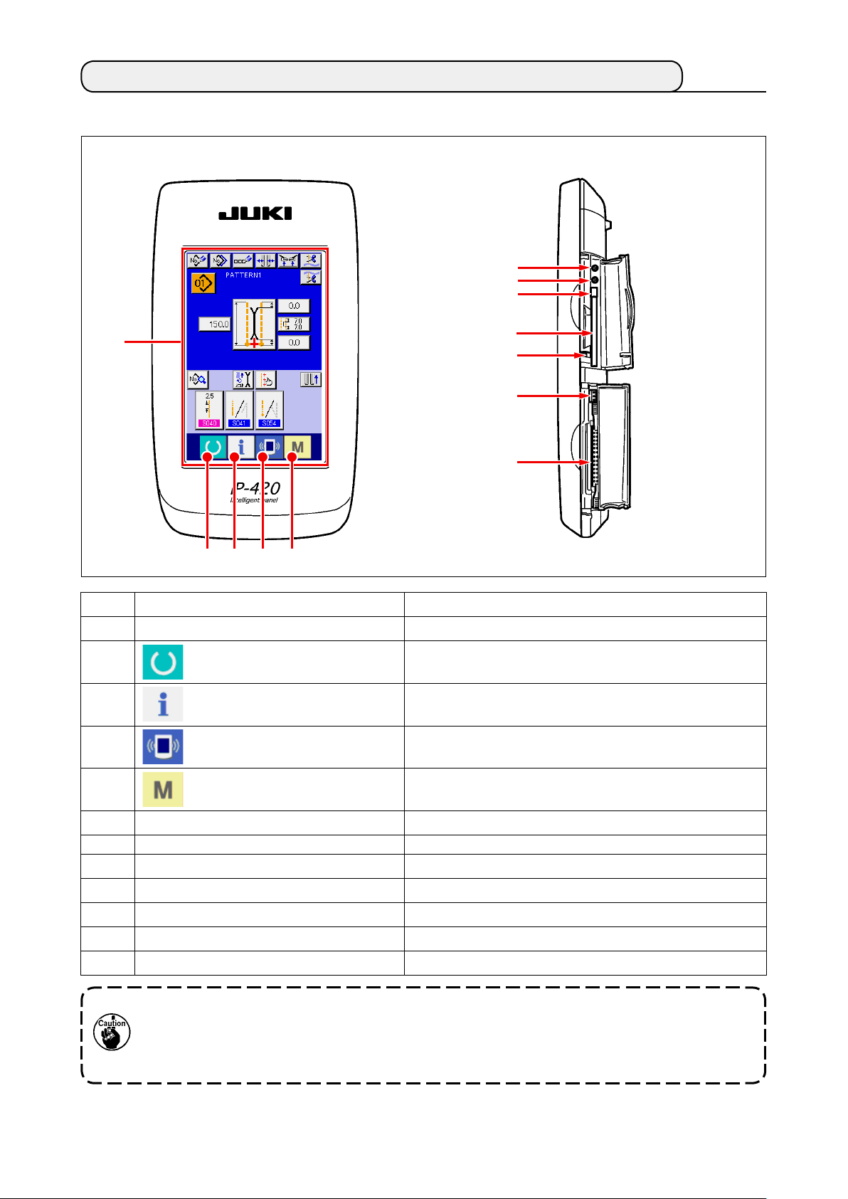
(1) Conguration of IP-420
[ Front ] [ Right side ]
❻
❼
❽
❶
Symbol
❶
❷
❸
❹
❷ ❸ ❹ ❺
Name
TOUCH PANEL, LCD display section
READY key
INFORMATION key
COMMUNICATION key
❾
Description
Change-over of the data input screen and the sewing screen is
performed.
Change-over of the data input screen and the information screen is
performed.
Change-over of the data input screen and the communication
screen is performed.
❺
❻
❼
❽
❾
Contrast control
Brightness control
CompactFlash (TM) eject button
CompactFlash (TM) slot
Cover detection switch
Connector for external switch
Connector for control-box connection
MODE CHANGEOVER key
Change-over of the data input screen and the mode change-over
screen which performs various details setting.
1. Lightly press the target key on the touch panel with a ngertip to operate the IP-420. If you
operate with any means other than your ngertip, the IP-420 can malfunction or the glass
surface of the touch panel can be scratched or break.
2. When READY key is pressed rst after turning ON the power, origin retrieval of the clamp
foot is performed. At this time, the clamp foot moves. So, be careful.
− 24 −
Page 29
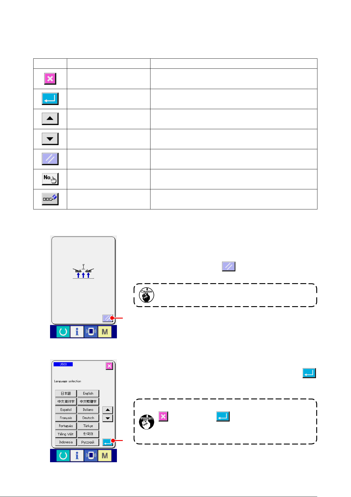
(2) Buttons used in common
Buttons that perform common operation in the respective screens of IP-420 are as described below.
Pictograph Name
CANCEL button
ENTER button Data changed are determined.
UP SCROLL button This button scrolls button or display upward.
DOWN SCROLL button This button scrolls button or display downward.
RESET button This button releases error and the like.
NUMBER INPUT button Ten keys are displayed and input of number can be performed.
CHARACTER INPUT button Character input screen is displayed.
(3) Basic operation
Description
Pop-up screen is closed. In case of the data change screen, the data during
changing can be cancelled.
Turn ON the power switch.
①
First, turn ON the power switch.
Reset pop-up screen is displayed after displaying WELCOME
screen. Press RESET button A.
When RESET button is pressed, the binder goes up. So,
be careful.
A
Next, language selection pop-up screen is displayed. After select-
ing the language you desire to display, press ENTER button
. Then the independent sewing input screen (screen A) of the
B
gure below is displayed.
When ending the selection screen with CANCEL button
B
or ENTER button without performing the lan-
guage selection, the language selection screen is dis-
played whenever the power is turned ON.
− 25 −
Page 30
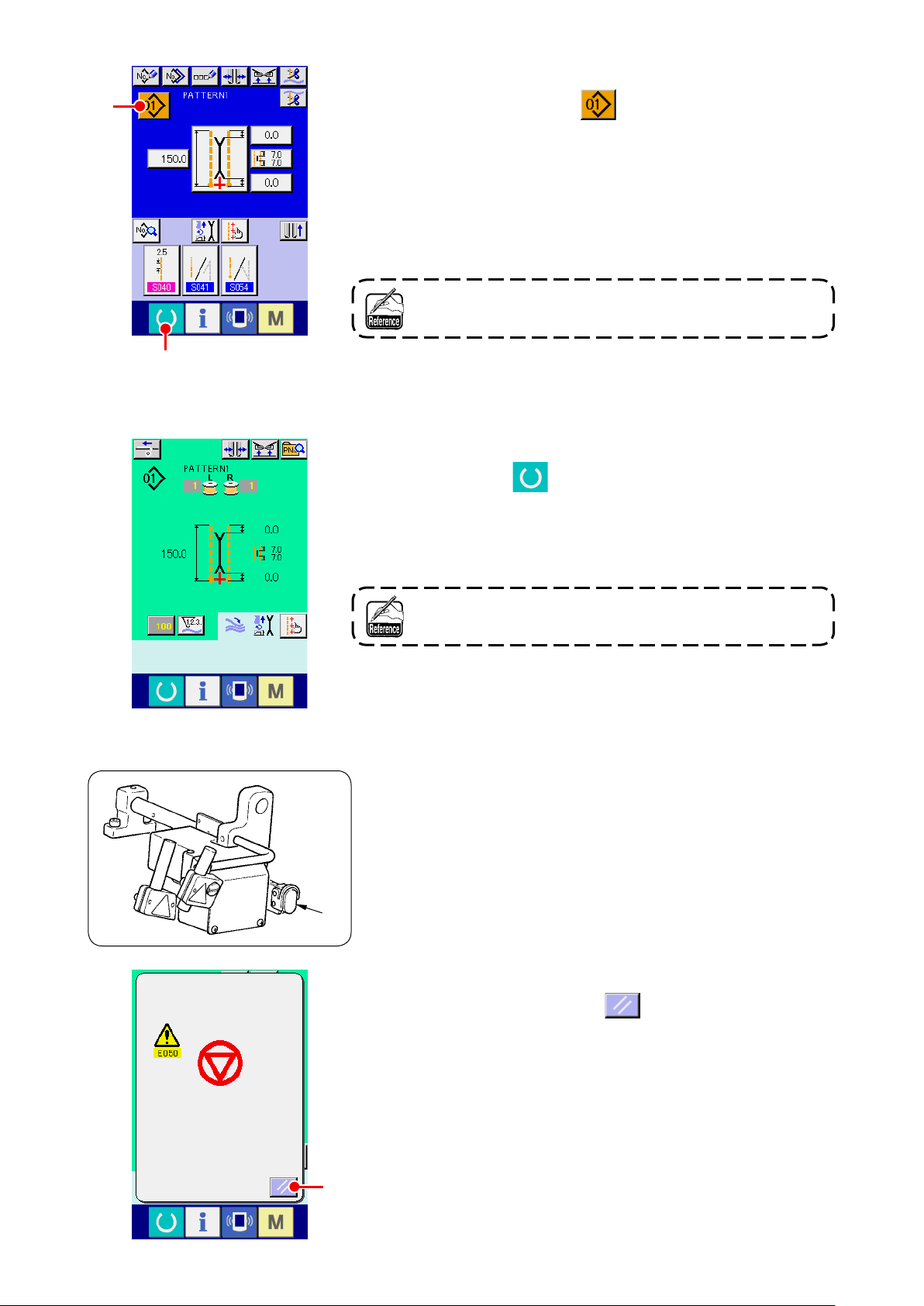
Select pattern No. you desire to sew.
②
C
D
The independent sewing
input screen (screen A)
When PATTERN NO. button C is pressed, the pattern No.
can be selected. For the selecting procedure of pattern No., see
"VI-7.(1) Performing the selection of pattern" p. 42
At the time of your purchase, pattern Nos. 1 to 10 have been reg-
istered. Change the sewing data in accordance with the sewing
types for use. (The number to which the pattern has not been
registered is not displayed.)
For the detailed explanation of input screen, see "VI-3.
EXPLANATION OF THE BASIC SCREEN" p. 28 .
Start sewing
③
When READY key D is pressed in the independent sewing
input screen (screen A), the green sewing screen (screen B) is
displayed and the sewing operation is started by the pedal opera-
tion.
Sewing screen (screen B)
E
For the detailed explanation of input screen, see "VI-3.
EXPLANATION OF THE BASIC SCREEN" p. 28 .
To stop the device during operation
④
When temporary stop switch E is pressed during sewing, the
device can be stopped.
At this time, the error screen is displayed to inform that stop switch
is pressed. When RESET button F is pressed, the error is
released and the screen returns to the input screen.
F
− 26 −
Page 31

Depress back the pedal at the time of selection of the long
⑤
H
and wide type.
At the time of selection of the long and wide type, when
depressing back the pedal in the green sewing screen (screen B),
the conrmation screen as shown on the left side is displayed.
When the clamp foot moves to the back by depressing back the
pedal, it retreats with the ap presser closed. This screen is to
conrm whether material is put on the clamp foot.
Conrming message saying that "Clamp foot moves to the back
G
with ap presser closed. Remove material on the clamp foot" is
displayed.
When there is no material on the clamp foot, press CLAMP FOOT
BACK button G and the clamp foot moves to the back with
the ap presser closed. At the same time, the conrming screen is
released and the screen returns to the sewing screen.
When canceling clamp foot back, press CANCEL button
, and the ap presser is opened. Then the clamp foot does
H
not move to the back. At the same time, the conrming screen is
released and the screen returns to the sewing screen.
When there is material on the clamp foot, be sure to press
CANCEL button H and remove the material.
Then depress back the pedal again to move the clamp
foot to the back.
− 27 −
Page 32

3. EXPLANATION OF THE BASIC SCREEN
(1) Input screen (Independent sewing mode)
A B C D E F
H
I
J
K
L
M
G
N
O
P
Q
R
S
U
V
T
Symbol Name of button Description
NEW CREATION button Independent sewing pattern new creation screen is displayed and new register of the pattern
A
COPY button
B
CHARACTER INPUT button Character input screen is displayed and the name can be inputted to the pattern data.
C
TYPE OF WELT CHANGE-OVER button Type of welt change-over screen is displayed, and change-over of type of welt and adjust-
D
CLAMP UP PROHIBITION AT SEWING END
E
button
NEEDLE THREAD TRIMMING button When this button is pressed, needle thread trimming knife comes down and the needle
F
BOBBIN THREAD TRIMMING button Bobbin thread trimming knife opens while this button is pressed.
G
PATTERN NO. LIST button Pattern No. list screen is displayed and the pattern data can be selected.
H
SEWING MODE CHANGE-OVER button
I
L SIZE LENGTH SETTING button In case of L size sewing, sewing length is set.
J
MOTION MODE SETTING button
K
STACKER MOTION/STOP CHANGE-OVER button
L
SEWING DATA DISPLAY button Sewing pattern edit screen is displayed. Detailed sewing data that are not displayed in the
M
PATTERN NAME display Names that are inputted in pattern Nos. are displayed.
N
CORNER KNIFE MOTION POSITION AT
O
SEWING START SETTING button
CENTER KNIFE SETTING button Center knife data edit screen is displayed, and center knife cutting position of sewing start
P
CORNER KNIFE MOTION POSITION AT
Q
SEWING END SETTING button
MARKING LIGHT SETTING button
R
CLAMP FOOT MOVE button Clamp foot is moved to the front or to the back.
S
SEWING DATA SHORTCUT button Shortcut buttons (max. 4 items) of the sewing data that are set in customizing in the sewing
T
FLAP DROP DATA AT SEWING START SET-
U
TING button
FLAP DROP DATA AT SEWING END SET-
V
TING button
data can be performed.
Independent sewing copy source pattern list screen is displayed and the pattern can be copied.
ment of parallelism of the binder can be performed.
When this button is pressed, the clamp is returned in the lowered state at sewing end.
It is convenient to use this button at the time of adjusting the marking light or trial sewing.
thread trimming operating screen is displayed.
Sewing mode is selected.
With/without of motion of sewing machine motor, center knife and corner knife.
This button selects motion/stop and of stacker.
input screen can be selected and edited.
Cutting position of corner knife at sewing start is set.
and sewing end is set.
Cutting position of corner knife at sewing end is set.
Marking light setting screen is displayed. Selection of sewing reference and setting
of marking irradiation position, , or is performed.
screen are displayed.
Flap concealed stitching data at sewing start or is set.
Flap concealed stitching data at sewing end or is set.
* It is possible to customize display/non-display of the respective buttons.
For the details, refer to
"VI-13. CUSTOMIZING THE DATA INPUT SCREEN" p. 75
.
− 28 −
Page 33

(2) Sewing screen (Independent sewing mode)
A B D
C
G
H
E
F
Symbol Name of button Description
INTERLINING SUPPLY button When this button is pressed, interlining is supplied.
A
I
* This is displayed when “With” of , automatic interlining supplying device is set
with the optional setting.
TYPE OF WELT CHANGE-OVER button Type of welt change-over screen is displayed and change-over of type of welt and adjustment
B
CLAMP UP PROHIBITION AT SEWING END
C
button
DIRECT PATTERN LIST button Direct pattern list screen is displayed and selection of the sewing data can be performed.
D
COUNTER CHANGE-OVER button When this button is pressed, the display of sewing counter and number of pcs. counter is
E
COUNTER VALUE CHANGE button This button changes the counter value which is displayed at present.
F
BOBBIN THREAD (RIGHT) REMAINING
G
AMOUNT VALUE
BOBBIN THREAD (LEFT) REMAINING
H
AMOUNT VALUE
MARKING LIGHT SETTING button Marking light setting screen is displayed, and changeover of marking light irradiation position
I
of parallelism of the binder can be performed.
When this button is held pressed, the clamp is returned in the lowered state at sewing end.
It is convenient to use this button at the time of adjustment of marking light or trial sewing.
changed over.
* This button is displayed only when both sewing counter and number of pcs. counter are
ON.
This button detects reecting light from bobbin and informs that bobbin thread remaining
amount is running out. When one stitching completes, the counter value is subtracted, and
the count-up screen is displayed when “0” is reached.
* This button is displayed only when the reecting light from bobbin is detected.
This button detects reecting light from bobbin and informs that bobbin thread remaining
amount is running out. When one stitching completes, the counter value is subtracted and the
count-up screen is displayed when “0” is reached.
* This button is displayed only when the reecting light from bobbin is detected.
and setting of change of marking light set value , and
are performed.
* It is possible to customize display/non-display of the respective buttons.
For the details, refer to
"VI-13. CUSTOMIZING THE DATA INPUT SCREEN" p. 75
.
− 29 −
Page 34

(3) Input screen (Alternate sewing mode)
A B C D E F
H
I
J
G
O
P
Q
R
T
U
V
M
L
K
Symbol Name of button Description
NEW CREATION button Alternate sewing data new creation screen is displayed and new register of data can be
A
COPY button Alternate sewing data copy source No. list is displayed and alternate sewing data can be
B
CHARACTER INPUT button Character input screen is displayed and name input can be performed n the alternate sewing
C
TYPE OF WELT CHANGE-OVER button Type of welt change-over screen is displayed ,and change-over of type of welt and adjust-
D
CLAMP UP PROHIBITION AT SEWING END
E
button
NEEDLE THREAD TRIMMING button Needle thread trimming knife comes down and needle thread trimming in motion screen is
F
BOBBIN THREAD TRIMMING button Bobbin thread trimming knife opens while this button is pressed.
G
ALTERNATE SEWING DATA NO. LIST button Alternate sewing data No. list screen is displayed and alternate sewing data can be selected.
H
SEWING MODE CHANGE-OVER button
I
L SIZE LENGTH SETTING button
J
SEWING DATA DISPLAY button Sewing pattern edit screen is displayed. This button selects detailed sewing data that are not
K
STACKER MOTION/STOP CHANGE-OVER
L
button
MOTION MODE SETTING button
M
MARKING LIGHT SETTING button
N
NEXT SEWING DATA CHANGE-OVER button Sewing pattern to be sewn next which is enclosed with yellow frame is changed over.
O
CORNER KNIFE MOTION POSITION AT
P
SEWING START SETTING button
CENTER KNIFE SETTING button Center knife data edit screen is displayed and center knife cutting position of sewing start
Q
CORNER KNIFE MOTION POSITION AT
R
SEWING END SETTING button
CLAMP FOOT MOVE button Clamp foot is moved to the front or to the back.
S
T, V
U, W
FLAP CONCEALED STITCHING DATA AT
SEWING START SETTING button
FLAP CONCEALED STITCHING DATA AT
SEWING END SETTING button
N
S
performed.
copied.
data.
ment of parallelism of the binder can be performed.
When this button is held pressed, clamp is returned in the lowered state at the time of sew-
ing end.
It is convenient to use this button at the time of adjusting marking light or trial sewing.
displayed.
Sewing mode is selected.
In case of L size sewing, sewing length is set.
displayed in the input screen and can edit the data.
This button selects motion/stop and of stacker.
With/without motion of sewing machine motor, center knife and corner knife.
Marking light setting screen is displayed, and selection of sewing reference and
setting of marking irradiation position , or can be performed.
* This is not displayed when ap priority sewing selection is ON.
Cutting position of corner knife at sewing start is set.
and sewing end .
Cutting position of corner knife at sewing end is set.
Flap concealed stitching data at sewing start or is set.
Flap concealed stitching data at sewing end or is set.
W
* It is possible to customize display/non-display of the respective buttons.
For the details, refer to
"VI-13. CUSTOMIZING THE DATA INPUT SCREEN" p. 75
.
− 30 −
Page 35

(4) Sewing screen (Alternate sewing mode)
A B C
D
G
H
I
E
F
Symbol Name of button Description
INTERLINING SUPPLYING button When this button is pressed, interlining is supplied.
A
TYPE OF WELT CHANGE-OVER button Type of welt change-over screen is displayed, and change-over of type of welt and adjust-
B
CLAMP UP PROHIBITION AT SEWING END
C
button
DIRECT PATTERN LIST button Direct pattern list screen is displayed and selection of the sewing data can be performed.
D
COUNTER CHANGE-OVER button When this button is pressed, display of sewing counter and number of pcs. counter is
E
COUNTER VALUE CHANGE button Counter value which is displayed at present is changed.
F
NEXT SEWING DATA CHANGE-OVER button Sewing pattern to be sewn next which is enclosed with yellow frame is changed over.
G
BOBBIN THREAD (RIGHT) REMAINING
H
AMOUNT VALUE
BOBBIN THREAD (LEFT) REMAINING
I
AMOU’NT VALUE
MARKING LIGHT SETTING button Marking light setting screen is displayed, and changeover of marking light irradiation position
J
J
* This is displayed when “With” of , automatic interlining supplying device is set
with the optional setting.
ment of parallelism of the binder can be performed.
When this button is held pressed, the clamp is returned in the lowered state at the time of
sewing end.
It is convenient to use this button at the time of adjustment of marking light and trial sewing.
changed over. This button is displayed only when both sewing counter and number of pcs.
counter are ON.
* This is not displayed when ap priority sewing selection is ON.
This button detects reecting light from bobbin and informs that bobbin thread remaining
amount is running out. When one stitching completes, the counter value is subtracted, and
the count-up screen is displayed when “0” is reached.
* This button is displayed only when the reecting light from bobbin is detected.
This button detects reecting light from bobbin and informs that bobbin thread remaining
amount is running out. When one stitching completes, the counter value is subtracted, and
the count-up screen is displayed when “0” is reached.
* This button is displayed only when the reecting light from bobbin is detected.
and setting of change of marking light set value , and
are performed.
* It is possible to customize display/non-display of the respective buttons.
For the details, refer to
"VI-13. CUSTOMIZING THE DATA INPUT SCREEN" p. 75
− 31 −
.
Page 36

(5) Input screen (Cycle sewing mode)
A B C D E F
H
G
I
K
J
L
M
N
Symbol Name of button Description
NEW CREATION button Cycle sewing data No. new creation screen is displayed and new register of cycle sewing
A
COPY button Cycle sewing data copy source No. list screen is displayed and cycle sewing data can be
B
CHARACTER INPUT button Character input screen is displayed and name can be inputted to the cycle sewing data.
C
TYPE OF WELT CHANGE-OVER button Type of welt change-over screen is displayed and change-over of type of welt, and adjust-
D
CLAMP UP PROHIBITION AT SEWING END
E
button
NEEDLE THREAD TRIMMING button Needle thread trimming knife comes down and the needle thread trimming in motion screen
F
BOBBIN THREAD TRIMMING button While this button is held pressed, bobbin thread trimming knife opens.
G
CYCLE SEWING DATA NO. LIST button Cycle sewing data No. list screen is displayed and the cycle sewing data can be selected.
H
PATTERN DATA EDIT button Edit of pattern data which have been registered to cycle sewing data can be performed.
I
PATTERN DATA EDIT button (blank) When this blank button is pressed, the pattern list screen to register the pattern data to the
J
CYCLE RETURN button Pattern data to be sewn next which is displayed with white emphasis is moved forward by
K
CYCLE FEED button Pattern data to be sewn next which is displayed with white emphasis is moved backward by
L
PATTERN DATA DELETION button Pattern data which is displayed with white emphasis is deleted from register.
M
CLAMP FOOT MOVE button Clamp foot is moved to the front or to the back.
N
data can be performed.
copied.
ment of parallelism of the binder can be performed.
When this button is held pressed, the clamp is returned in the lowered state at the time of
sewing end.
It is convenient to use at the time of adjustment of marking light and trial sewing.
is displayed.
* For the editing procedure, refer to
28
cycle sewing data is displayed, and it is possible to select and register the pattern data.
one. In case of rst pattern, it moves to the last pattern.
one. In case of the last pattern, it moves to the rst pattern.
"3-(1) Input screen (Independent sewing mode)" p.
* It is possible to customize display/non-display of the respective buttons.
For the details, refer to
"VI-13. CUSTOMIZING THE DATA INPUT SCREEN" p. 75
− 32 −
.
Page 37

(6) Sewing screen (Cycle sewing mode)
A B C
D
I
H
E
J
K
F
G
Symbol Name of button Description
INTERLINING SUPPLYING button When this button is pressed, interlining is supplied.
A
TYPE OF WELT CHANGE-OVER button Type of welt change-over screen is displayed, and change-over of type of welt and adjust-
B
CLAMP UP PROHIBITION AT SEWING END
C
button
DIRECT PATTERN LIST button Direct pattern list screen is displayed and selection of the sewing data can be performed.
D
CYCLE DATA display All pattern data that have been registered to the cycle sewing data are displayed.
E
COUNTER CHANGE-OVER button When this button is pressed, display of sewing counter and number of pcs. counter is
F
COUNTER VALUE CHANGE button Counter value which is displayed at present is changed.
G
BOBBIN THREAD (RIGHT) REMAINING
H
AMOUNT
BOBBIN THREAD (LEFT) REMAINING
I
AMOUNT
LEFT SCROLL button Pattern data to be sewn next is moved forward by one. In case of the rst pattern, it moves
J
RIGHT SCROLL button Pattern data to be sewn next is moved backward by one. In case of the last pattern, it moves
K
MARKING LIGHT SETTING button Marking light setting screen is displayed, and changeover of marking light irradiation position
L
L
* This is displayed when “With” of , automatic interlining supplying device is set
with optional setting.
ment of parallelism of the binder can be performed.
When this button is held pressed, the clamp is returned in the lowered state at the time of
sewing end.
It is convenient to use this button at the time of adjustment of marking light and trial sewing.
changed over. This button is displayed only when both sewing counter and number of pcs.
counter are ON.
This button detects light from bobbin and informs that bobbing thread remaining amount is
running out. When one stitching completes, the counter value is subtracted, and the count-
er-up screen is displayed when “0” is reached.
* This button is displayed only when the reecting light from bobbin is detected.
This button detects reecting light from bobbin and informs that bobbin thread remaining
amount is running out. When one stitching completes, the counter value is subtracted, and
the counter-up screen is displayed when “0” is reached.
* This button is displayed only when the reecting light from bobbin is detected.
to the last pattern.
to the rst pattern.
and setting of change of marking light set value , and
are performed.
* It is possible to customize display/non-display of the respective buttons.
For the details, refer to
"VI-13. CUSTOMIZING THE DATA INPUT SCREEN" p. 75
− 33 −
.
Page 38
4. USING THE COUNTER
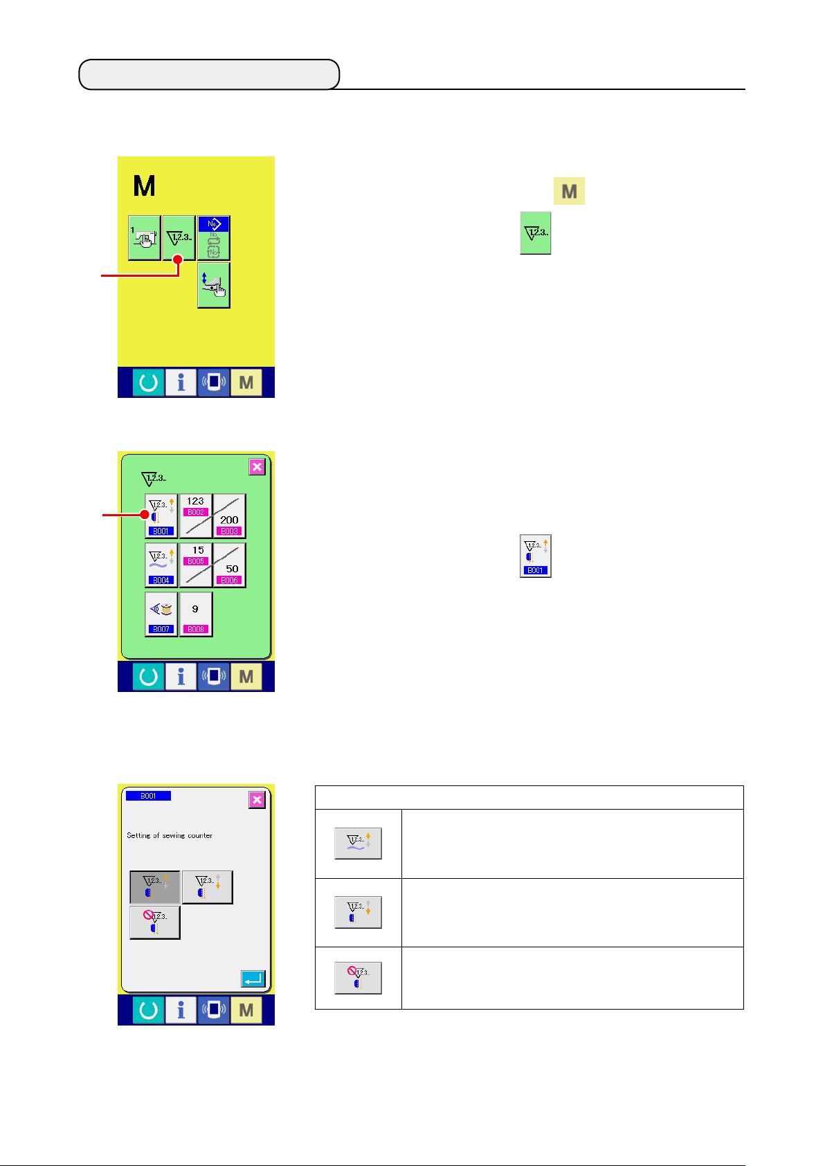
(1) Setting procedure of the counter
Display the counter setting screen.
①
Press MODE CHANGEOVER key from the input screen and
COUNTER SETTING button A is displayed on the screen.
A
B
Press this button and “COUNTER SETTING screen (screen A)” is
displayed.
Select the kind of counter.
②
There are three kinds of counters with this sewing machine, sew-
ing counter, number of pcs. counter and bobbin thread remaining
amount adjustment counter.
Press sewing counter button B in “counter setting screen
(screen A)”, and “sewing counter setting screen (screen B)” is
displayed. Then the kind of counter can be set.
Counter setting screen
(Screen A)
Sewing counter setting
screen (Screen B)
[ Sewing counter ]
UP counter
Every time one sewing is performed, the existing value is counter
up. When the existing value is equal to the set value, the count-
up screen is displayed.
DOWN counter
Every time one sewing is performed, the existing value is counted
down. When the existing value is reached to “0”, the count-up
screen is displayed.
Counter unused
Sewing counter is set to the prohibition.
− 34 −
Page 39

C
Counter setting screen
(Screen A)
Number of pcs. counter
(Screen C)
Press NUMBER OF PCS. COUNTER button C In “Counter
setting screen (screen A)”, and “number of pcs. setting screen
(screen C)” is displayed. Then the kind of counter can be set.
[ Number of pcs. counter ]
UP counter
Every time one of nished products is sewn, the existing value is
counted up.
* In case of independent sewing : 1 time of sewing
In case of alternate sewing : 2 times of sewing
In case of cycle sewing : 1 time of cycle sewing
The number given in each case above is regarded as one of
nished products.
When the existing value is equal to the set value, the count-up
screen is displayed.
DOWN counter
Every time one of nished products is sewn, the existing value
is counted down. When the existing value is reached to “0”, the
count-up screen is displayed.
Counter unused
Number of pcs. counter is set to the prohibition.
− 35 −
Page 40

Changing the target value of the counter
③
In case of the sewing counter, press button D, and in case
D
of the number of pcs. counter, press button E, and “ Nu-
E
merical setting pop-up screen (screen D)” Is displayed. Then the
target value of counter can be set.
Here, input the target value of counter. When “0” is inputted to the
target value of counter, only the existing value is displayed during
sewing and the count-up screen is not displayed.
Numerical setting pop-up screen
(screen D)
Change the existing value of counter
④
F
In case of the sewing counter, press button F and in case
G
of the number of pcs. counter, press G, and “ Numerical
setting pop-up screen (screen E)” is displayed. Then the existing
value of counter can be set.
Here, input the existing value of counter.
Numerical setting pop-up screen
(screen E)
− 36 −
Page 41

(2) Releasing procedure of count-up
During the sewing work, the count-up condition is reached the count-
up screen is displayed and the buzzer sounds. Press CLEAR button
A to reset the counter, and the screen returns to the sewing
screen. And, counting starts again.
A
(3) Counter value changing procedure during sewing
A
Display the counter value change screen
①
When you desire to change the counter value during the sewing
work, press COUNTER VALUE CHANGE button A on the
sewing screen. Counter value change screen is displayed.
Change the counter value
②
Change the counter value with TEN keys to B or ▼▲
button C ( D ).
F
B
Determine the counter value
③
Press ENTER button E and the data is determined. When
you desire to clear the counter value, press CLEAR button F.
E
DC
− 37 −
Page 42

5. USING THE BOBBIN THREAD AMOUNT ADJUSTMENT COUNTER
(1) Setting procedure of the bobbin thread remaining amount adjustment counter
Display the counter setting screen
①
Press MODE CHANGEOVER key from the input screen,
COUNTER SETTING button A is displayed on the screen..
A
B
Press this button and “Counter setting screen (screen A)” is dis-
played.
Set the bobbin thread remaining amount adjustment counter
②
to ON.
Press BOBBIN THREAD REMAINING AMOUNT ADJUSTMENT-
COUNTER MOTION SETTING button B, and “Bobbin
thread remaining amount adjustment counter setting pop-up
screen (screen B)” is displayed. Then the bobbin thread remaining
amount adjustment counter motion (ON/OFF) can be set.
Set the bobbin thread remaining amount adjustment value
③
Counter setting screen
(Screen A)
Bobbin thread remaining amount
adjustment value setting screen
(Screen B)
[ Bobbin thread remaining amount detection ]
Bobbin thread remaining amount adjustment counter ON :
The counter detects the reecting light from bobbin and informs
that bobbin thread remaining amount is running out. Every time
one sewing is performed, the counter value is subtracted and the
count-up screen is displayed when the existing value is reached
to “0”.
Bobbin thread remaining amount adjustment counter OFF :
Bobbin thread remaining amount detection is set to the prohibi-
tion.
− 38 −
Page 43

Counter setting screen
(Screen A)
Press BOBBIN THREAD REMAINING AMOUNT ADJUSTMENT
VALUE SETTING button C and the bobbin thread remain-
ing amount adjustment value setting screen (screen B) is dis-
played.
C
Here, input the bobbin thread remaining amount adjustment value
(0 to 9).
Set the number of times of sewing from detecting run-out of bob-
bin thread by the sensor to performing the count-up display.
Bobbin thread remaining amount
adjustment value setting screen
(Screen B)
When you desire to lengthen the remaining length bobbin
thread :
→ Decrease the number (toward “0”).
When you desire to shorten the remaining length of bob-
bin thread :
→ Increase the number (toward 9).
− 39 −
Page 44
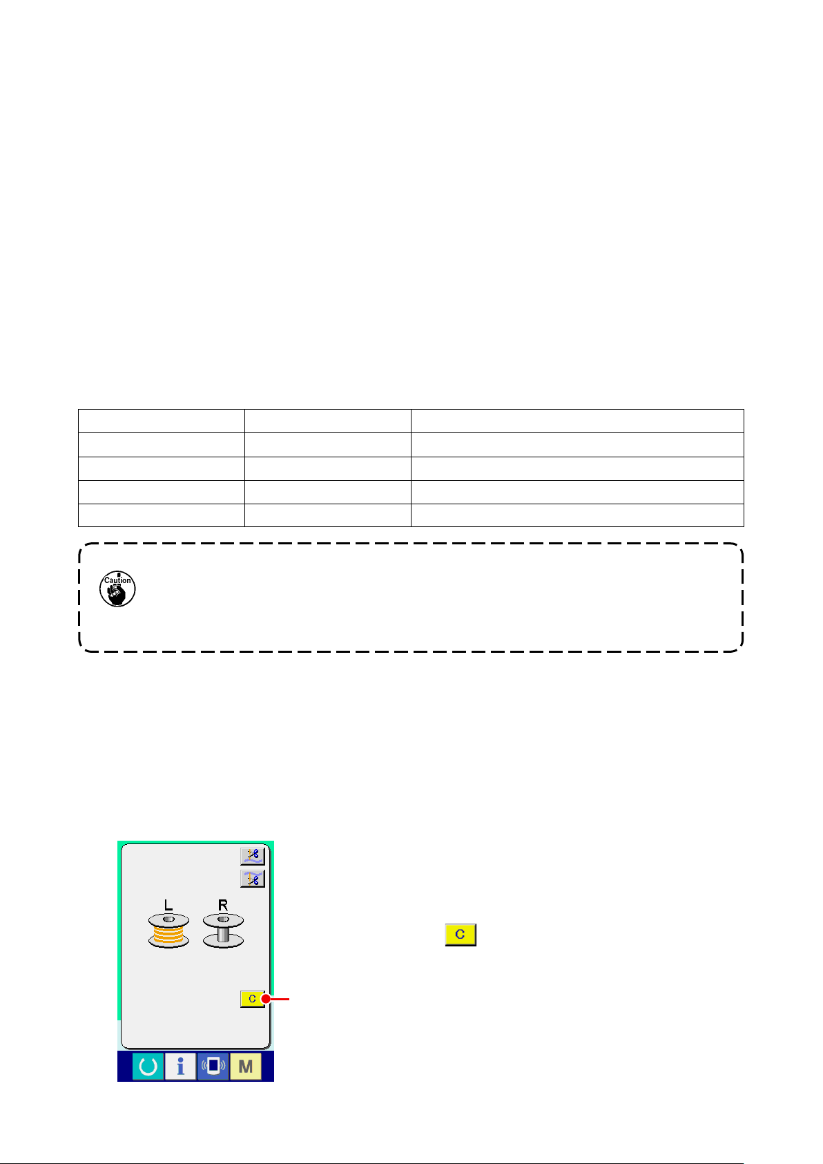
Setting of the bobbin thread remaining amount adjustment counter
*
*
1) Set the bobbin thread remaining amount adjustment counter to the value shown in the table below.
2) Start the sewing to perform regular sewing. In case of test sewing, adjust the sewing length to that to be
sewn in the actual process.
3) As you continue sewing, the bobbin thread is gradually reduced and the run-out of bobbin thread is dis-
played in the screen when the bobbin sensor detects the reecting light.
4) At this time, check the length of bobbin thread remaining on the bobbin and properly modify the value on
the counter.
5) Increasing the counter value by 1 will shorten the remaining length of bobbin thread by the amount that
is consumed for one time of sewing.
6) The remaining length of bobbin thread at the time when the indication of run-out of bobbin thread varies
by a certain extent. This variation depends on the type of thread, sewing length and the winding way of
thread.
The remaining length of bobbin thread is shown, as a guide, in the table below. Correct the counter value
in accordance with sewing conditions and the like so that the bobbin thread does not completely run out
during sewing.
[ The table shows the counter value when the sewing length is set to 150 mm ]
Thread count Counter value Bobbin thread remaining length for reference (m)
#40 1 0.4 to 2.6
#50 2 0.2 to 2.6
#60 2 0.4 to 2.8
#80 3 0.1 to 3.0
•
1.
2.
• The value of bobbin thread remaining amount counter is cleared by inputting the value of the
The bobbin thread remaining length has to be re-adjusted in the case described below.
When the sewing length for the sewing product has been changed.
When the thread count of bobbin thread has been changed.
bobbin thread remaining amount adjustment counter.
7) If the bobbin has run out of thread, the bobbin thread remaining amount detecting device is incapable of
performing “bobbin thread remaining amount detection”. So, it is very important to specify a value on the
bobbin thread remaining amount adjustment counter to allow the device to give the indication of “run-out
of bobbin thread” when the sufcient amount of bobbin thread remains.
(2) Releasing procedure of the bobbin thread remaining amount detection count-up
When the bobbin thread remaining amount counter value becomes “0”
at the sewing end, the count-up screen is displayed and the buzzer
sounds. Replace the bobbin thread of the bobbin where the bobbin
thread remains few.
When CLEAR button A is pressed, the bobbin thread remaining
amount counter value is reset and the screen returns to the sewing
screen.
A
− 40 −
Page 45

6. CHANGING THE SEWING MODE
Display the sewing mode selection screen
①
Press SEWING MODE CHANGEOVER key A and the
mode change-over screen is displayed.
B
A
Select the sewing mode
②
Press MODE SELECTION button B and the indication of button is changed.
When the independent
sew is selected
Determine the sewing mode.
③
When the alternate sewing
is selected
When the cycle sewing is
selected
Press MODE CHANGEOVER key A and the data input screen of the selected sewing mode is
displayed.
Independent sewing input
screen
Alternate sewing input
screen
− 41 −
Cycle sewing input screen
Page 46

7. USING THE SEWING PATTERN
(1) Performing the selection of pattern
Display the input screen
①
When the input screen of independent sewing mode, alternate sewing mode and cycle sewing mode is
displayed, the selection of pattern can be selected.
By customizing the sewing screen, the selection of pattern can be performed from the sewing screen as
well.
Call the pattern list screen
②
Press PATTERN LIST button , or A and the pattern list screen is displayed.
A AA
Select the pattern
③
Press pattern data you desire to select B.
B
Determine the pattern
④
C
B
C
B
When ENTER button C is pressed, the pattern is selected and the screen returns to the input
screen.
C
− 42 −
Page 47

(2) Performing the new creation of pattern
Display the input screen
①
When the input screen of independent sewing mode, alternate sewing mode and cycle sewing mode is
displayed, the new creation of pattern can be performed.
Call the sewing pattern new creation screen
②
Press NEW CREATION button , or A, and the pattern new creation screen is dis-
played.
A
Input the pattern No.
③
A A
Input pattern No. you desire to newly create with ten keys to B. It is possible to retrieve pat-
tern No. which has not been registered yet with ▼▲ button C and D.
B
DC
Determine the pattern No.
④
E
B
DC
E
E
B
DC
When ENTER button E is pressed, the pattern No. to newly create is determined and the screen
returns to the input screen.
− 43 −
Page 48

(3) Copying the pattern
The pattern which has been already registered can be copied to the sewing pattern which has not registered
yet. Copying of overwriting of pattern is prohibited. So, when you desire to overwrite, perform it after erasing
the pattern once.
→ For the erasing procedure, see
When performing copying the pattern No. which has been already registered, copy disapproved
error (E401) is displayed.
Display the input screen
①
When the input screen of independent sewing mode, alternate sewing mode and the cycle sewing mode
is displayed, it is possible to copy.
A A A
"VI-7.(4) Erasing the pattern" p. 46
.
Call the pattern No. list screen of the copy source
②
Press PATTERN COPY button , or A, and the copy source pattern list screen is dis-
played.
− 44 −
Page 49

Select the pattern of copy source
③
Select the pattern of copy source from PATTERN LIST button B.
Next, press COPY DESTINATION NO. INPUT button C and the copy destination input screen
(screen B) is displayed.
C
B
Input the pattern No. of copy destination
④
B
Copy destination No. input screen (screen A)
C
B
C
Input the pattern No. of copy destination with ten keys to B. It is possible to retrieve the pat-
6tern No. which has not been used yet with ▼▲ buttons ( C and D ).
E
B
E
B
Start copying
⑤
C
D
B
E
C D C D
Copy destination No. input screen (screen B)
When ENTER button E is pressed, copying starts. The pattern No. which has been copied is in
the selection state and returns to the copy source pattern list screen (screen A).
− 45 −
Page 50

(4) Erasing the pattern
Display the input screen
①
When the input screen of independent sewing mode, alternate sewing mode and cycle sewing mode is
displayed, it is possible to erase the pattern.
Call the pattern list screen
②
Press PATTERN LIST button , or A and the pattern No. list screen (screen A) is dis-
played.
A
Select the pattern to be erased
③
A
A
Select the pattern to be erased from pattern list button B.
Next, press ERASE button C and the pattern erase conrmation screen is displayed.
B
Determine the pattern to be erased
④
B
C
Pattern No. list screen (screen A)
B
C
Press ENTER button in the pattern erase conrmation screen and the pattern is erased.
When CANCEL button is pressed, the screen returns to the original screen A without erasing the
pattern.
− 46 −
C
Page 51

(5) Naming the pattern
Display the input screen
①
When the input screen of independent sewing mode, alternate sewing mode and cycle sewing mode is
displayed, it is possible to input the name to the pattern data.
Call the character input screen
②
Press CHARACTER INPUT button A and the character input screen (screen B) is displayed.
B
A
A
Data input screen (screen A)
F
B
E
F
E
A
F
B
E
C D
Input the character
③
Character input screen (screen B)
C D
C D
It is possible to input the character by pressing CHARACTER button B you desire to input. As many as
14 characters of characters ( to and to ) and symbols ( , , , , and
) can be inputted. Cursor can be moved with CURSOR LEFT MOVE button C and CURSOR
RIGHT MOVE button D. When you desire to erase the inputted character adjust the cursor to the
position of the character you desire to erase and press ERASE button E.
End the character input
④
Press ENTER button F to end the character input. After the end, the inputted character is dis-
played at the upper part of the input screen.
− 47 −
Page 52
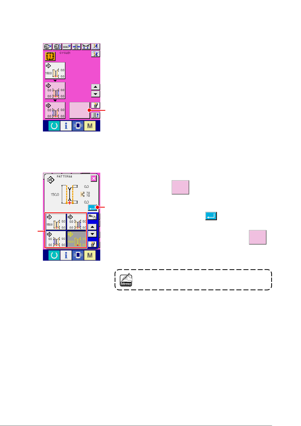
(6) Editing procedure of the cycle sewing data
Display the cycle sewing input screen
①
When the input screen of cycle sewing ode is displayed, it is pos-
sible to edit the cycle sewing data.
A
Cycle sewing input screen
(Screen C)
B
Pattern list screen
(Screen B)
Register the pattern data
②
Press BLANK button A and the pattern list screen (screen
B) is displayed.
C
Select the pattern data you desire to register from PATTERN LIST
button B and press ENTER button C. Then the selected
pattern data is registered to the blank section.
When the rst pattern data is registered, BLANK button
is displayed in the second place. Repeat the operation of ② in
D
case of need.
As many as 6 pattern data can be registered to the cycle
sewing data.
− 48 −
Page 53

D
Erase the registered pattern data
③
Press ERASE button E and the pattern data which is dis-
played with white emphasis is erased. Select the pattern data you
desire to erase with UP/DOWN SCROLL buttons and
and erase it.
F
F
Cycle sewing input screen
(Screen C)
G
E
Edit the registered pattern data
④
The pattern data which is displayed with white emphasis
is the pattern data to be sewn next. So, move it in accor-
dance with the sewing work.
Press PATTERN DATA button G you desire to edit and
the pattern data edit screen (screen D) is displayed in pop-up.
Refer to
28
"VI-3.(1) Input screen (Independent sewing mode)" p.
.
Pattern data edit screen
(Screen D)
− 49 −
Page 54

8. CHANGING THE SEWING DATA
(1) Changing procedure of the sewing data
Display the input screen
①
When the input screen of independent sewing mode, alternate sewing mode and cycle sewing mode is
displayed it is possible to change the swing data.
The sewing data which are frequently used can be registered to SEWING DATA SHORTCUT button
B
in the input screen and be set directly. In addition, the detailed sewing data can be set by pressing
C
A
B
A
A
B
A.
1. When changing the sewing data of cycle sewing mode, press PATTERN DATA EDIT button
and it is possible to change.
2. In case of alternate sewing mode, SEWING DATA SHORTCUT button
3. For SEWING DATA SHORTCUT button
SCREEN" p. 75.
4. For the details of sewing data, refer to "① Items that are displayed in the data input screen of
VI-8-(2) Sewing data list" p. 51.
Select the sewing data to be changed
②
, refer to "VI-13. CUSTOMIZING THE DATA INPUT
B
is not displayed.
B
C
Press A and the sewing data list screen (screen A) is dis-
played. Then select the data you desire to change.
Data items which are not used due to the shape are not dis-
played. So, be careful.
Sewing data list screen (Screen A)
− 50 −
Page 55

(2) Sewing data list
Items that are displayed in the data input screen
①
No. Item
Motion mode change-over
With/without of motion of sewing machine motor, center knife and corner
knife is selected.
Cloth feed mode
Cloth feed, sewing machine
thread trimming
Sewing mode change-over
Sewing mode is selected.
* In case of alternate sewing, ap priority sewing is set with .
L size sewing Left ap sewing
Right ap sewing Flap priority sewing
Cloth feed, sewing machine
thread trimming and center
knife mode
Cloth feed, sewing machine
thread trimming, center
knife and corner knife mode
Setting range
/
Edit unit
- - -
- - -
Initial value
L size setting
In case of L size sewing, the sewing length is set.
* It is possible to set only when setting L size sewing .
* For the long and wide type, it is possible to set up to 250 mm.
(However, it is possible to set up to 300 mm without corner knife.)
Marking light irradiation position change-over
Sewing start irradiation/sewing end irradiation/center irradiation is selected.
Sewing start irradiation Sewing end irradiation
Center irradiation
Flap concealed stitching data (Left sewing start)
Position of sewing start of left-hand ap is adjusted.
* It is possible to set only when is set to ap sewing.
Flap concealed stitching data (Left sewing end)
Position of sewing end of left-hand ap is adjusted.
* It is possible to set only when is set to ap sewing.
18.0 to
220.0
/
0.1mm
- - -
–9.9 to 9.9
/
0.1mm
–9.9 to 9.9
/
0.1mm
150.0mm
0.0mm
0.0mm
Flap concealed stitching data (Right sewing start)
Position of sewing start of right-hand ap is adjusted.
* It is possible to set only when is set to ap sewing.
. . . Item that is not displayed due to other setting state
− 51 −
–9.9 to 9.9
/
0.1mm
0.0mm
Page 56

No. Item
Flap concealed stitching data (Right sewing end)
Position of sewing end of right-hand ap is adjusted.
* It is possible to set only when is set to ap sewing.
Setting range
/
Edit unit
–9.9 to 9.9
/
0.1mm
Initial value
0.0mm
Center knife actuating position setting
Cutting position of center knife at sewing start/sewing end is set.
* Be sure to adjust with every gauge so that the position meets the top of
letter V of corner knife.
Sewing start center knife
position
Sewing end center knife
position
Corner knife actuating position at sewing start
Cutting position of corner knife at sewing start is set.
Corner knife actuating position at sewing end
Cutting position of corner knife at sewing end is set.
Marking light setting
Marking light irradiation position in each case of sewing start irradiation/
sewing end irradiation/center irradiation is set. When set value 0.0n mm,
the sewing position is the same as the marking light irradiation position.
Use this function when irradiating the marking light to the position that is
different from the sewing position.
Sewing start irradiation Sewing end irradiation
0.0 to 25.0
/
0.1mm
* APW-895L
only
Max. 30.0
–9.9 to 9.9
/
0.1mm
–9.9 to 9.9
/
0.1mm
–100.0 to
100.0
* Sewing start
irradiation :
–80.0 to 100.0
/
0.1mm
7.0mm
0.0mm
0.0mm
0.0mm
Center irradiation
Roller stacker stop/motion change-over
Stop/motion of roller stacker is selected.
* It is displayed only when is set to roller stacker mounting.
Stop Motion
Clamp bar stacker stop/motion change-over
Stop/motion of clamp bar stacker is selected.
* It is displayed only when is set to clamp bar stacker mounting.
Stop Motion
. . . Item that is not displayed due to other setting state
- - -
- - -
− 52 −
Page 57

Items that are displayed in the sewing data list screen
②
No. Item
Flap priority sewing selection
Flap priority sewing mode is selected.
* It is possible to set only when alternate sewing mode is set.
Flap priority sewing prohib-
ited
Flap priority sewing mode
Setting range
/
Edit unit
- - -
Initial value
Selection of automatic changeover of marking light irradiation position
When is sewing start irradiation or sewing end irradiation, the marking
irradiation position is automatically changed over after end of sewing.
* This function does not move at the time of alternate sewing mode and
cycle sewing mode.
Stop Motion
Flap forced stop data
When ap sewing end is not detected, the machine stops after sewing as
long as the set length from rear reference position.
* It is possible to set only when is set to ap sewing.
Lockstitch pitch
Sewing pitch of lockstitch section is set.
Selection of condensation/back tack at sewing start
Condensation/back tack at sewing start is selected.
Condensation Back tack
- - -
0.0 to 10.0
/
0.1mm
2.0 to 3.4
/
0.1mm
- - -
5.0mm
2.5mm
Number of condensation stitches at sewing start
Number of condensation stitches at sewing start is set.
*
It is possible to set only when is set to selection of condensation.
Condensation pitch at sewing start
Condensation sewing pitch at sewing start is set.
*
It is possible to set only when is set to selection of condensation.
First stitch pitch of condensation sewing at sewing start
First stitch pitch of condensation sewing at sewing start is set.
*
It is possible to set only when is set to selection of condensation.
*
It is possible to set only when is set to selection of condensation/
back tack detailed setting.
3 to 19
/
1 stitch
0.5 to 1.5
/
0.1mm
0.1 to 1.5
/
0.1mm
5 stitches
1.0mm
1.0mm
. . . Item that is not displayed due to other setting state
− 53 −
Page 58

No. Item
Second stitch pitch of condensation sewing at sewing start
Second stitch pitch of condensation sewing at sewing start is set.
*
It is possible to set only when is set to selection of condensation.
*
It is possible to set only when is set to selection of condensation/
back tack detailed setting.
Setting range
/
Edit unit
0.1 to 1.5
/
0.1mm
Initial value
1.0mm
Third stitch pitch of condensation sewing at sewing start
Third stitch pitch of condensation sewing at sewing start is set.
*
It is possible to set only when is set to selection of condensation.
*
It is possible to set only when is set to selection of condensation/
back tack detailed setting.
Number of back tack stitches at sewing start
Number of back tack stitches at sewing start is set.
*
It is possible to set only when is set to selection of back tack.
Back tack pitch at sewing start
Back tack sewing pitch at sewing start is set.
*
It is possible to set only when is set to selection of back tack.
Back tack tie stitch pitch at sewing start
Back tack tie stitch at sewing start is set.
*
It is possible to set only when is set to selection of back tack.
0.1 to 1.5
/
0.1mm
1 to 12
/
1 stitch
0.5 to 3.0
/
0.1mm
–2.0 to 2.0
/
0.1mm
1.0mm
3 stitches
2.0mm
–1.5mm
First stitch pitch of return of back tack at sewing start
First stitch pitch of return section of back tack sewing at sewing start is set.
*
It is possible to set only when is set to selection of back tack.
*
It is possible to set only when is set to selection of condensation/
back tack detailed setting.
Second stitch pitch of return of back tack at sewing start
Second stitch pitch of return section of back tack sewing at sewing start is set.
*
It is possible to set only when is set to selection of back tack.
*
It is possible to set only when is set to selection of condensation/
back tack detailed setting.
. . . Item that is not displayed due to other setting state
− 54 −
0.1 to 3.0
/
0.1mm
0.1 to 3.0
/
0.1mm
2.0mm
2.0mm
Page 59

No. Item
Third stitch pitch of return of back tack at sewing start
Third stitch pitch of return section of back tack sewing at sewing start is set.
*
It is possible to set only when is set to selection of back tack.
*
It is possible to set only when is set to selection of condensation/
back tack detailed setting.
Setting range
/
Edit unit
0.1 to 3.0
/
0.1mm
Initial value
2.0mm
Selection of condensation/back tack at sewing end
Selection of condensation/back tack at sewing end is performed.
Condensation Back tack
Back tack pitch at sewing start
Back tack sewing pitch at sewing start is set.
*
It is possible to set only when is set to selection of back tack.
Condensation pitch at sewing end
Condensation sewing pitch at sewing end is set.
*
It is possible to set only when is set to selection of condensation.
The last stitch pitch of condensation
The last stitch pitch of condensation sewing at sewing end is set.
*
It is possible to set only when is set to selection of condensation.
* It is possible to set only when is set to selection of condensation/
back tack detailed setting.
- - -
3 to 19
/
1 stitch
0.5 to 1.5
/
0.1mm
0.1 to 1.5
/
0.1mm
5 stitches
1.0mm
1.0mm
Pitch of one stitch before the last stitch of condensation
Pitch of one stitch before the last stitch of condensation sewing at sewing
end is set.
*
It is possible to set only when is set to selection of condensation.
* It is possible to set only when is set to selection of condensation/
back tack detailed setting.
Pitch of two stitches before the last stitch of condensation
Pitch of two stitches before the last stitch of condensation sewing at sew-
ing end is set.
*
It is possible to set only when is set to selection of condensation.
* It is possible to set only when is set to selection of condensation/
back tack detailed setting.
Number of back tack stitches at sewing end
Number of back tack stitches at sewing end is set.
* It is possible to set only when is set to selection of back tack.
0.1 to 1.5
/
0.1mm
0.1 to 1.5
/
0.1mm
1 to 12
/
1 stitch
1.0mm
1.0mm
3 stitches
. . . Item that is not displayed due to other setting state
− 55 −
Page 60

No. Item
Back tack pitch at sewing end
Back tack sewing pitch at sewing end is set.
* It is possible to set only when is set to selection of back tack.
Setting range
/
Edit unit
0.5 to 3.0
/
0.1mm
Initial value
2.0mm
First stitch pitch of return of back tack at sewing end
First stitch pitch of return section of back tack sewing at sewing end is set.
* It is possible to set only when is set to selection of back tack.
* It is possible to set only when
back tack detailed setting.
Second stitch pitch of return of back tack sewing at sewing end
Second stitch pitch of return section of back tack sewing at sewing end is set.
* It is possible to set only when is set to selection of back tack.
* It is possible to set only when
back tack detailed setting.
Third stitch pitch of return of back tack sewing at sewing end
Third stitch pitch of return section of back tack sewing at sewing end is set.
* It is possible to set only when is set to selection of back tack.
* It is possible to set only when
back tack detailed setting.
is set to selection of condensation/
is set to selection of condensation/
is set to selection of condensation/
0.1 to 3.0
/
0.1mm
0.1 to 3.0
/
0.1mm
0.1 to 3.0
/
0.1mm
2.0mm
2.0mm
2.0mm
The last stitch pitch of back tack at sewing end
The last stitch pitch of back tack at sewing end is set.
* It is possible to set only when is set to selection of back tack.
Compensation of back tack return at sewing end
Compensation value of back tack return at sewing end is set.
* It is possible to set only when is set to selection of back tack.
* It is possible to set only when compensates with pattern data.
–2.0 to 2.0
/
0.1mm
–2.0 to 2.0
/
0.1mm
–1.5mm
1.0mm
. . . Item that is not displayed due to other setting state
− 56 −
Page 61

No. Item
Stacking position
After moving clamp foot as far as the set distance from the position of cor-
ner knife, stacker is actuated. (+ : rear side, - : front side)
* Range of actuating amount is limited by the position of clamp foot at the
time of sewing end.
* Use clamp bar stacker or roller stacker. In addition, it is
possible to set only when roller stacker motion setting or
clamp bar stacker motion setting is performed.
Setting range
/
Edit unit
0 to 500mm
/
1mm
Initial value
0mm
Stacker timer 1
Roller rotation time is set. When material sensor has detected without
material before setting time, rotation stops.
* roller stacker option is used and it is possible to set only when
roller stacker motion is set.
Jump feed speed up to the position of sewing start
Jump feed speed up to the position of sewing start is set.
Jump feed speed up to the position of corner knife
Jump feed speed up to the position of corner knife is set.
Dart stretcher device stop/motion change-over
Stop/motion of dart stretcher device is selected.
* It is possible to set only when dart stretcher option is used.
0.0 to 9.9
/
0.1 sec.
3 to 8
/
1
3 to 6
/
1
- - -
0.5 sec.
5
5
Stop Motion
Automatic interlining supplying device stop/motion change-over
Stop/motion of automatic interlining supplying device is selected.
* It is possible to set only when automatic interlining supplying
option is used.
* Regarding the interlining supplying, when the pattern is not used, be
careful not to make the interlining come out from the top surface of the
table. When using next, press once the feeding button on the panel and
perform the feeding motion to cut.
Stop Motion
. . . Item that is not displayed due to other setting state
- - -
− 57 −
Page 62

No. Item
Flap length
Length of ap is set.
It is possible to set only when automatic interlining supplying de-
vice is selected to motion and sewing mode changeover is select-
ed to ap sewing.
* This setting is set to determine the interlining feeding length of automatic
interlining supplying device. Sewing length is determined by the detec-
tion of ap sensor.
Setting range
/
Edit unit
37.0 to
220.0
/
0.1mm
Initial value
150.0mm
Sewing speed under the high-speed mode
Number of revolutions at lockstitch section is set.
* It is possible to set only when sewing speed setting selection is
set to pattern data selection.
Sewing speed under the low-speed mode
Number of revolutions at condensation and back tack sewing sections is
set.
* It is limited by sewing speed under the high-speed mode.
* It is possible to set only when sewing speed setting selection is
set to the selection of pattern data.
* In case of back tack sewing, the upper limit of number of revolutions of
the actual low speed is limited to 1,500 sti/min.
1000 to
3000
/
100sti/min
1000 to
2500
/
100sti/min
2500sti/min
1500sti/min
. . . Item that is not displayed due to other setting state
− 58 −
Page 63

9. CHANGING THE MEMORY SWITCH DATA
(1) Changing procedure of the memory switch data
Display the memory switch data list screen
①
Press MODE CHANGE-OVER key and the memory switch
A
C
button A is displayed. When this button is pressed, the
memory switch data list (screen A) is displayed.
Select the memory switch button you desire to change
②
Press UP/DOWN SCROLL button or B and select
DATA ITEM button C you desire to change.
B
Memory switch data list screen
(Screen A)
− 59 −
Page 64

(2) Memory switch data list
Level 1
①
Memory switch data (level 1) are the motion data that the sewing machine has in common and the data
that operate on all sewing patterns in common.
Setting range
No. Item
Change-over of the position of clamp foot after sewing end
Position of clamp foot after sewing end is selected from Stop at front
end/Return to medium/Clamp return/Stop at rear end.
Stop at front end Return to medium
Clamp return Stop at rear end
/
Edit unit
- - -
Initial value
Front end motion start waiting time
Waiting time up to the start of front end motion of clamp foot is set.
* It is possible to set only when is set to the stop at front end.
Number of times of feeding of automatic interlining supplying at
sewing start
Number of times of feeding of automatic interlining supplying device at
sewing start is set.
* It is possible to set only when automatic interlining supplying
option is used.
Feeding length of automatic interlining supplying at sewing end
Feeding length of automatic interlining supplying device at sewing end
is set.
* It is possible to set only when automatic interlining supplying
device is used.
Thread trimming timing
Thread trimming timing after sewing is selected from Standard/Medi-
um/Longest and length of thread at sewing end is adjusted.
0.50 to
9.99
/
0.01 sec.
2 to 9
/
1
0 to 99.9
/
0.1mm
- - -
3.00 sec.
3
0mm
Standard 0 Medium 1
Longest 2
* When
dard value "0", needle thread may not be cut.
Stacker timer 2
Waiting time from the start of clamp motion to hold material on the
stacker base to release the material presser is set.
* It is possible to set only when clamp bar stacker option is
used.
. . . Item that is not displayed due to other setting state.
Zipper attachment is mounted and the setting is set to stan-
− 60 −
0.00 to
9.99
/
0.01 sec.
0.70 sec.
Page 65

No. Item
Stacker timer 3
Motion time of material sweeping bar is set.
* It is possible to set only when clamp bar stacker option is
used.
Setting range
/
Edit unit
0.00 to
9.99
/
0.01 sec.
Initial value
0.70 sec.
Stacker timer 4
Time to advance timing to release the sewing product by lifting clamp
foot is set.
When clamping a short sewing product, the amount to drop by tare is
adjusted.
* It is possible to set only when clamp bar stacker option is
used.
Sewing speed under the high-speed mode
Number of revolutions of lockstitch section is set.
* It is possible to set only when sewing speed setting selection
is set to memory switch.
Sewing speed under the low-speed mode
Number of revolutions of condensation and back tack sewing sections
is set.
* It is limited by sewing speed under the high-speed mode.
* It is possible to set only when sewing speed setting selection
is set to memory switch.
* In case of back tack sewing, the upper limit of number of revolutions
of the actual low speed is limited to 1,500 sti/min.
Soft start, rst stitch
Number of revolutions of rst stitch at sewing start is limited.
0.00 to
9.99
/
0.01 sec.
1000 to
3000
/
100
sti/min
1000 to
2500
/
100
sti/min
500 to
2500
/
100
sti/min
0.00 sec.
2500sti/min
1500sti/min
500sti/min
Soft start, second stitch
Number of revolutions of second stitch at sewing start is limited.
Soft start, third stitch
Number of revolutions of third stitch at sewing start is limited.
Return speed of clamp foot
Return speed of clamp foot is set.
. . . Item that is not displayed due to other setting state.
− 61 −
500 to
2500
/
100
sti/min
500 to
2500
/
100
sti/min
3 to 9
/
1
700sti/min
1000sti/min
7
Page 66

No. Item
Thread breakage detection
With/without thread breakage detection is selected.
Setting range
/
Edit unit
- - -
Initial value
With thread break-
age detection
Without thread
breakage detection
Flap presser motion mode
Motion order of ap presser is selected.
From right From left
Right/Left at the
same time
Side where ap is
put
* When right and left are simultaneously actuated with customizing of
pedal setting, this parameter is neglected and the right and left are
simultaneously actuated.
Clamp foot down order change-over
Lowering order of clamp foot is selected.
From right From left
Right/left at the
same time
- - -
- - -
* When right and left are simultaneously actuated with customizing of
pedal setting, this parameter is neglected and the right and left are
simultaneously actuated.
Folding plate motion mode
“Return/No return” of folding plate when corner knife projects is select-
ed.
Return No return
Binder pressure reduction rise prohibition
Pressure reduction rise of the binder at the time of jump feed is prohib-
ited.
Pressure reduc-
tion rise is prohib-
Pressure reduc-
tion rise
ited
Standing pedal continuous depressing timer effective/ineffective
change-over
Effective/ineffective of standing pedal continuous depressing
timer is selected.
* It is possible to set only when one-shot pedal is set.
- - -
- - -
- - -
Ineffective Effective
. . . Item that is not displayed due to other setting state.
− 62 −
Page 67

No. Item
Standing pedal continuous depressing timer
When performing sewing product setting work with the standing pedal
depressed, the time interval when the respective devices operate in
order is set.
* It is possible to set only when
one-shot pedal is set.
Setting range
/
Edit unit
0.1 to 2.0
/
0.1 sec.
Initial value
0.5 sec.
Condensation/back tack detailed setting
Detailed setting “Perform/Not perform” of pitch of condensation/back
tack section is selected.
Perform Not perform
Flap stopper position
In case of ap sewing, sewing start irradiation position of marking light
(distance from needle)is set
* Setting is only the irradiation position of marking light. Actual sewing
position is the ap end position detected by the ap sensor.
Stacker timer 5
Sets the waiting time of the stacker from the start of material grasping
operation to the release of the material
This setting is available when "Grasping stacker (optional)" is used.
Stacker timer 6
Sets the duration of operating the oscillating arm
This setting is available when "Grasping stacker (optional)" is used.
- - -
80.0 to
280.0
/
0.1mm
0.00 -
9.99/
0.01 sec
0.00 -
9.99/
0.01 sec
80.0mm
1.00 sec
1.50 sec
Number of stitches of grease-up
Number of stitches of sewing machine motion after replenishing grease
is indicated.
* When pressing CLEAR button, number of stitches is cleared to “0”.
Be sure to clear after replenishing grease.
Language selection
Language to be indicated in the panel is selected.
Japanese
Chinese (traditional) Chinese (simplied)
Spanish Italian
French German
Portuguese Turkish
Vietnamese Korean
Indonesian Russian
. . . Item that is not displayed due to other setting state.
English
− 63 −
- - - - - -
- - - No selection
Page 68

Level 2
②
Memory switch data (level 2) are the motion data that the sewing machine has in common and the data
that operate on all sewing patterns in common. The data are for the maintenance personnel and possi-
ble to edit by pressing the mode switch as long as 6 seconds.
Setting range
No. Item
Marking light mounting
Mounting/Non-mounting of marking light is selected. When “Non
mounting” is selected, marking light does not work.
Non mounting Mounting
/
Edit unit
- - -
Initial value
Sewing position selection
Mode that surely ends sewing at rear reference position, mode that
surely starts sewing from front reference position or the conventional
motion mode that changes sewing position according to the setting of
is selected.
* Front reference position : 80 mm from needle
Rear reference position : 300 mm from needle
For the long and wide type, it is 330 mm.
However, when
Conventional motion
mode
Sewing position
xed mode (Front
reference)
is set, it is 380 mm.
Sewing position
xed mode (Rear
reference)
Setting of solenoid valve for corner knife separate drive
Mounting/non mounting of solenoid valve for corner knife separate
drive is set.
Non mounting Mounting
- - -
- - -
Pedal operation mode change-over
Mode to be used for foot pedal is set.
7-step pedal mode 1-shot pedal mode
Excess rate of center knife cutting
Excess rate in terms of the speed of revolution of center knife can be
set.
− 64 −
- - -
300 to
500
/
1%
350%
Page 69

No. Item
Setting of intermittent feed prohibition
Perform/not perform intermittent feed sewing is selected.
* When performing intermittent sewing, the max. sewing speed of sew-
ing machine is limited 1,500 sti/min.
Setting range
/
Edit unit
- - -
Initial value
Perform intermittent
feed sewing
Not perform intermit-
tent feed sewing
Change-over of ap concealed stitching data edit reference
Making the ap concealed stitching data that is set from panel the
compensation value from the ap detecting end or the distance from
detecting sensor to sewing start is selected.
Flap detecting end
compensation
Sensor compensa-
tion
L size data range enlargement
Enlarging/not enlarging L size data range to max. 220 mm + 15 mm is
set. In case of the long and wide type, the size is enlarged to 250 mm
+ 50 mm.
* When performing sewing longer than 250 mm with
the long
and wide type, the corner knife does not work.
* In case of
the long and wide type, corner knife does not work
when a ap cloth is put in the area of +50 mm even when it is less
than 250 mm.
Not enlarging Enlarging
Selection of sewing speed of sewing machine setting
It is selected that either memory switch or pattern data performs setting
of sewing speed of sewing machine.
- - -
- - -
- - -
Memory switch Pattern data
Selection of reecting tape check mode
ON/OFF of reecting tape check mode is set.
When ON is set, the clamp foot is automatically comes lowered with
the rst clamp foot advance motion after turning ON the power and
deterioration check of reecting tape is performed.
* Clamp foot is automatically lowered. Be sure to use this function only
in case of shim type.
OFF ON
Selection of back tack return at sewing end compensation setting
It is selected that either memory switch or pattern data performs setting
of back tack return at sewing end compensation.
Memory switch Pattern data
- - -
- - -
− 65 −
Page 70

No. Item
Back tack return at sewing end compensation
Back tack return at sewing end compensation is set.
* It is possible to set only when is set to the memory switch
selection.
Setting range
/
Edit unit
−2.0 to
2.0
/
0.1mm
Initial value
1.0mm
Selection of mode change-over button display in the pattern list
screen
Mode change-over button is displayed in the pattern list screen and
data of different mode can be selected.
Non-display Display
Cycle sewing coupling function
Odd-numbered pattern can be coupled to even-numbered pattern and
as many as 12 steps can be sewn.
Only combination of 1 and 2, 3 and 4, 5 and 6, 7 and 8, 9 and 10, 11
and 12, 13 and 14, 15 and 16, 17 and 18, and 19 and 20 can be cou-
pled.
Coupling function
OFF
Coupling function
ON
Center knife lowering time
Center knife lowering time is set.
- - -
- - -
10 to 100
/
1
40
Center knife one-shot motion prohibition setting
With/without one-shot motion to properly cut the cutting position of
center knife on the side of the end of sewing is selected.
With one-shot mo-
tion
One-shot motion
prohibited
Clamp foot motor origin compensation
Origin of clamp foot motor is compensated.
- - -
−10.0 to
10.0
/
0.1mm
0.0mm
− 66 −
Page 71

No. Item
Corner knife motor origin compensation
Origin of corner knife motor is compensated.
Setting range
/
Edit unit
−5.0 to
5.0
/
0.1mm
Initial value
0.0mm
Marking light origin compensation (just under)
Origin of marking light motor is compensated. Origin is in the state that
it irradiates light just under and located at the position of 230 mm from
needle.
* In case of Long and wide type, light irradiation position is at
the position of 246 mm from the needle.
Marking light origin compensation (needle side)
Position of needle side from origin of marking light motor is compensat-
ed. Light irradiation position is 80 mm from needle.
* In case of Long and wide type, light irradiation position is at
the position of 96 mm from the needle.
Marking light origin compensation (operator side)
Position of operator side from origin of marking light motor is compen-
sated. Light irradiation position is 380 mm from needle.
* In case of Long and wide type, light irradiation position is at
the position of 396 mm from the needle.
−500 to
500
/
1 pulse
−500 to
500
/
1 pulse
−500 to
500
/
1 pulse
0 pulse
0 pulse
0 pulse
Back tack motor origin compensation
Origin of back tack motor is compensated.
−30 to 30
/
1 pulse
0 pulse
− 67 −
Page 72

10. PERFORMING OPTIONAL SETTING
(1) Changing procedure of the optional setting
Displaying the 2nd screen of the operation-mode changeover
①
A
screen.
When you keep operation-mode changeover key held
B
pressed for six seconds, right-scroll button
A is displayed
on the screen.
When you press this button, the 2nd screen (screen A) of the op-
eration-mode changeover screen is displayed.
Displaying the option setting list screen
②
Option setting button B is displayed on the screen.
When you press this button, option setting list screen (screen B)
is displayed.
Second screen of the
mode changeover screen
(Screen A)
D
Optional setting list screen
(Screen B)
C
Selecting the option setting you want to change
③
Press up/down scroll buttons C to select the data item
button D you want to change.
− 68 −
Page 73

(2) Optional setting list
By setting the optional mounted state, it is possible to perform the respective optional operations.
Setting range
No. Item
Clamp bar stacker mounting/not mounting is set
/
Edit unit
- - -
Initial value
Not mounting Mounting
Roller stacker mounting/not mounting is set.
Not mounting Mounting
Sets mount/unmount of the grasping stacker device mount/unmount
Unmount Mount
Dart stretcher mounting/not mounting is set.
* However, in case of dart stretcher mounting, Gauge size set-
ting is limited to 8 to 12 mm.
* In case of the long and wide type, the dart stretcher does not
work.
Not mounting Mounting
Vacuum device mounting/not mounting is set.
* In case of the long and wide type, the vacuum device does
not work.
Not mounting
- - -
Not mounting
- - -
Unmount
- - -
Not mounting
- - -
Not mounting
Not mounting Mounting
Automatic interlining supplying device mounting/not mounting is
set.
* In case of the long and wide type, the automatic interlining
supplying device does not work.
Not mounting Mounting
Zipper attachment mounting/not mounting is set.
* However, in case of zipper attachment mounting, Gauge size
setting is limited to 16 to 20 mm.
* In case of the long and wide type, the zipper attachment does
not work.
Not mounting Mounting
- - -
Not mounting
- - -
Not mounting
− 69 −
Page 74

11. CHANGING THE DEVICE SETTING
(1) Changing procedure of the device setting
Displaying the 2nd screen of the operation-mode changeover
①
A
screen.
When you keep operation-mode changeover key held
pressed for six seconds, right-scroll button A is displayed
on the screen.
When you press this button, the 2nd screen (screen A) of the op-
eration-mode changeover screen is displayed.
Displaying the device setting list screen
②
Second screen of the
mode changeover screen
(Screen A)
Device setting button B is displayed on the screen.
When you press this button, the device setting list screen is dis-
B
played.
Selecting the device setting you want to change
③
Select the data item button C you want to change.
C
Device setting list screen
(Screen B)
− 70 −
Page 75

(2) Device setting list
By setting the type of device, it is possible to operate according to the type.
No. Item
Gauge size
Gauge size of sewing machine is set.
* For the long and wide type, the range is enlarged to 22 to 32
mm.
* Corner knife motion is changed according to the set value of gauge
size.
* When Dart stretcher device is mounted, the range is limited to
8 to 12 mm and Zipper attachment is mounted, 16 to 20 mm.
Setting range
/
Edit unit
8 to 20
( 22 to 32 )
/
2 mm
Initial value
10 mm
Long and wide type selection
It is set when using the long and wide type.
Standard :
Standard clamp mounting, Sewing size 220 mm
Long and wide type :
Clamp foot for long and wide type mounting, Sewing
size 250 mm
The type has been set according to the mounted
clamp foot type at the time of delivery. Do not select
any other than the mounted clamp foot type since
interference occurs.
- - -
− 71 −
Page 76
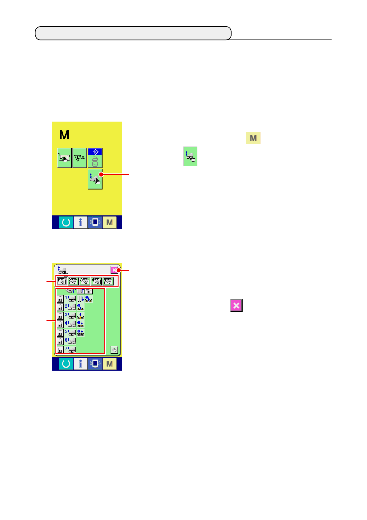
12. CUSTOMIZING THE PEDAL OPERATION
Operation functions of “Binder down”, “Flap presser down”, etc. in terms of the number of the respective de-
pressing steps of the pedal can be optionally registered in accordance with the using conditions.
In addition, the customized pedal operation data can have as many as 5 kinds. Select and use them.
(1) Method to select and use the customized data
Display the pedal customizing screen
①
Press MODE CHANGEOVER key and PEDAL CUSTOMIZ-
ING button A is displayed on the screen.
Press this button and the pedal customizing screen (screen A) is
A
displayed.
B
C
Pedal customizing screen
(Screen A)
Select from button B 5 kinds of pedal operation that are regis-
②
D
tered as customized. At this time, the contents of selected pedal
operation data are displayed at C.
When SCREEN END button D is pressed, the selected
③
pedal operation data is determined and the screen returns to the
original screen.
− 72 −
Page 77

(2) Customizing the pedal operation data
A
B
C
Press button A, and set whether to make the clamp foot
①
recede or not with the pedal depressed to the reverse step.
Display Description
To make clamp foot recede
Not to make clamp foot recede
D
Press button
②
, and set whether or not the interlining press-
B
er actuate with the pedal depressed to the reverse step.
Display Description
To actuate
Not to actuate
Press button
③
and set whether or not to lock the respec-
C
tive pedal operations of rst to seventh steps.
In case of “lock”, even when the pedal is released, the motion
state by pedal operation is held unless the pedal is depressed to
the reverse step or reset of pedal is performed.
Display Description
To lock
Pedal motion function setting screen
(Screen A)
Not to lock
Press button D, and the pedal motion function setting
④
screen (screen A) is displayed. Then the motion function to be
registered to the number of the respective pedal steps can be set.
− 73 −
Page 78

Functions below can be registered from rst step in order. Func-
⑤
tions that can be registered are in the state of button as
, and displayed in order. When the button is pressed, the color
changes and the function is registered. The number of pedal
F
E
steps is advanced with ▲▼ button
pedal steps is returned with
F, it becomes the state before
E. When the number of
one.
When functions are registered up to the last, ENTER button
is displayed. Press it to determine the registered data.
G
G
* It is possible to clear and register the number of pedal steps.
* When the function is determined without registering MACHINE START , knee switch start is applied.
* Whether or not the clamp foot comes down from right or left is determined by clamp foot lowering
order change-over. When right and left are set to the same time, even if the independent motion is set in
this screen, the right and the left actuate at the same time.
* Whether or not the ap presser comes down from right or left is determined by ap presser lowering
order change-over.
When right and left are set to the same time, even If the independent motion is set in this screen, the right
and the left actuate at the same time.
Display Description Display Description
Dart stretcher (optional) Binder down
Vacuum suction Flap presser one side down
Clamp foot one side down Flap presser remaining side down
Clamp foot remaining side down Machine start
− 74 −
Page 79

13. CUSTOMIZING THE DATA INPUT SCREEN
Buttons displayed in the data input screen can be customized in accordance with the customers’ using con-
ditions.
(1) Customizing procedure
Display the customizing screen of the input screen
①
Keep pressing MODE CHANGEOVER key for three sec-
is displayed on the
A
A
onds, and CUSTOMIZE button
screen.
When this button is pressed, the customizing screen of the input
screen is displayed.
B
F
C
D
E
G
H
I
J L
K
Select the conditions of buttons
②
Every time the buttons from
to L are pressed, display/non dis-
B
play of the buttons can be changed over. Customize and use the
buttons in accordance with the customers’ using conditions.
Symbol Display
B
C
D
E
F
G
H
Non dis-
play
Description Initial state
Pattern list button
Flap concealed stitching data
(Left sewing start)
Center knife motion position setting
Flap concealed stitching data
(Left sewing end)
Sewing mode change-over
Corner knife motion position at sewing start
L size setting
I
J
K
L
Corner knife motion position at sewing end
Stacker stop/motion change-over
Motion mode change-over
Marking light setting
− 75 −
Page 80

M
Register the sewing data to SEWING DATA CUSTOMIZING
③
button
Up to 4 sewing data can be registered to SEWING DATA CUS-
TOMIZE buttons M.
Register and use the sewing data that are frequently used.
When pressing CUSTOMIZING button M you desire to register,
the sewing data list (screen A) is displayed.
Select the sewing data to be registered
④
Select the sewing data you desire to register with SEWING DATA
button N.
When the selected button is pressed twice, the selection is re-
leased.
Register the data to the customizing button
⑤
When ENTER button O is pressed, register to the cus-
tomizing button ends, and the screen returns to the customizing
screen of the input screen. The registered sewing data is dis-
played on CUSTOMIZING button M.
N
O
Sewing data list screen
(Screen A)
The data below have been registered in order from the left at the time of your purchase.
a. Lockstitch pitchy
b. Condensation/back tack at sewing start selection
c. Condensation/back tack at sewing end selection
d. Dart stretcher stop/motion change-over
− 76 −
Page 81

14.
PERFORMING THE CUSTOMIZING SETTING OF THE SEWING SCREEN
Buttons displayed in the data input screen can be customized in accordance with the customers’ using condi-
tions.
(1) Customizing procedure
Display the customizing screen of the sewing screen
①
Keep pressing MODE CHANGEOVER key for three sec-
A
B
F
C
D
E
K
J L
G
H
I
onds and SEWING SCREEN CUSTOMIZING button
displayed on the screen.
Press this button and the customizing screen of sewing screen is
displayed.
Set the conditions of buttons
②
Every time the buttons from
to L are pressed, button display/
B
non display can be changed over. Customize and use the buttons
in accordance with the customers’ using conditions.
Symbol Display
B
C
D
Non dis-
play
Description Initial state
Pattern list button
Flap concealed stitching data
(Left sewing start)
Center knife motion position setting
A is
E
F
G
H
I
J
K
L
Flap concealed stitching data (Left
sewing end)
Sewing mode change-over
Corner knife motion position at sewing start
L size setting
Corner knife motion position at sewing end
Stacker stop/motion change-over
Motion mode change-over
Marking light setting
− 77 −
Page 82

M
N
Register the direct pattern.
③
When DIRECT PATTERN REGISTER button
is pressed, the
M
direct pattern register list screen (screen A) is displayed.
In the direct pattern list screen, the pattern data of independent
sewing/alternate sewing/cycle sewing can be freely registered up
to 30.
Register and use the pattern data that are frequently used. Press
PATTERN LIST button N and the direct pattern selection screen
(screen B) is displayed.
Direct pattern list screen
(Screen A)
Q
O
Direct pattern selection screen
(Screen B)
Select the pattern you desire to register with PATTERN SELEC-
TION button O.
In addition, the ten keys are displayed by pressing NO. INPUT
button R and the pattern you desire to register can be selected
P
R
by inputting the ten keys.
When the selected button is pressed again, the selection is
released.
When ENTER button
is pressed, register to the direct button is
P
completed and the screen returns to the direct pattern list screen
(screen A).
When MODE CHANGEOVER button
is pressed, the sewing
Q
mode is changed over to independent sewing → alternate sewing
→ cycle sewing.
The direct buttons have not been registered at the time of your purchase.
− 78 −
Page 83

15. USING THE INFORMATION
There are three functions below, in the information function.
Display the information screen
①
Ⓑ
Ⓐ
A
Information screen
(screen A)
Press INFORMATION key
the input screen and the information screen (screen A) is dis-
played.
Maintenance inspection information
Ⓐ
Oil replacement (grease-up) time, needle replacement time,
cleaning time, etc. are specied, and when the specied
time has passed, the warning notice can be performed.
Ⓒ
See
"VI-15.(1) Observing the maintenance inspection
information" p. 80.
Production control information
Ⓑ
By means of function to display target production and
actual production, the target achieving consciousness of a
line or a group is enhanced and also the progress can be
conrmed in one glance.
See
"VI-15.(3) Observing the production control infor-
mation" p. 82 and "VI-15.(4) Performing setting of the
production control information" p. 84.
of the switch seat section in
A
Operation measurement information
Ⓒ
Information on machine operating situation, machine op-
erating rate, pitch time, machine time, and machine speed
can be displayed.
See
"VI-15.(5) Observing the operation measurement
information" p. 86.
− 79 −
Page 84

(1) Observing the maintenance inspection information
Display the maintenance information screen
①
Press MAINTENANCE INSPECTION INFORMATION SCREEN
A
B
DISPLAY button
of the information screen.
A
Three items of the information below are displayed in the mainte-
nance inspection information screen.
• Needle replacement
(1,000 stitches) :
D
C
• Cleaning time (hour) :
• Oil replacement time
(hour) :
Interval
to inform the inspection and remaining time D up to
C
replacement are displayed in the respective item buttons B.
Also, the remaining time up to the replacement can be cleared.
Perform CLEAR of the remaining time up to the replacement
②
Press ITEM button
you desire to clear and the replacement
B
time clear screen is displayed.
Press CLEAR button E, and the remaining time up to the
E
replacement is cleared.
− 80 −
Page 85

Display the threading diagram
③
Press THREADING button E displayed in the maintenance
inspection information screen and the needle thread threading
screen is displayed.
See when performing threading.
E
(2) Releasing procedure of the warning
When the specied inspection time is reached, the warning screen is
B
displayed. In case of clearing the inspection time, press CLEAR button
A. The inspection time is cleared and the pop-up is closed. If
A
not, press CANCEL button B and close the pop-up. Every time
one sewing is completed, the warning screen is displayed until the
inspection time is cleared.
Warning Nos. of the respective items are as follows.
• Needle replacement : A201
• Cleaning time : A202
• Oil replacement time : A203
− 81 −
Page 86

(3) Observing the production control information
It is possible to designate the start, display the number of pieces of production from the start to the existing
time, display the number of pieces of production target, etc. in the production control screen. There are two
kinds of display ways for the production control screen.
[ In case of displaying from the information screen ]
Display the production control screen
①
A
Ⓐ
Ⓑ
Press PRODUCTION CONTROL SCREEN DISPLAY button
in the information screen. The production control screen is
A
displayed.
The production control screen is displayed.
: Existing target value
Ⓐ
Number of pieces of the target of sewn products at the pres-
Ⓒ
Ⓓ
ent time is automatically displayed.
: Actual results value
Ⓑ
Number of pieces of the sewn products is automatically dis-
Ⓔ
played.
: Final target value
Ⓒ
Number of pieces of the nal target of sewn products is dis-
played.
: Pitch time
Ⓓ
Time (second) required for one process is displayed.
: Number of times of thread trimming
Ⓔ
Number of times of thread trimming per process is displayed.
Refer to "VI-15.(4) Performing setting of the production control information" p. 84, and input Ⓒ
number of pieces, Ⓓ time (unit : second) and Ⓔ number of times.
− 82 −
Page 87

[ In case of displaying from the sewing screen ]
Display the sewing screen
①
Press READY key A in the input screen and the sewing
screen is displayed.
A
Display the production control screen
②
B
Press INFORMATION key
in the sewing screen and the
B
production control screen is displayed.
The contents of display and the functions are common to “In case
of displaying from the information screen”.
− 83 −
Page 88

(4) Performing setting of the production control information
Display the production control screen
①
Refer to
tion" p. 82
A
B
C
Input the nal target value
②
First, input the number of pieces of the target of production in the
process to which sewing is performed from now on.
When FINAL TARGET VALUE button A of item ① is
pressed, the nal target value input screen is displayed.
Input the value you desire with ten keys or UP/DOWN buttons.
"VI-15.(3) Observing the production control informa-
and display the production control screen.
After the input, press ENTER button D.
D
Input the pitch time
③
Next, input the pitch time required for one process.
When PITCH TIME button B of item ① is pressed, the
pitch time input screen is displayed.
Input the value you desire with ten keys or UP/DOWN buttons.
After the input, press ENTER button E.
E
Input the number of times of thread trimming
④
Next, input the number of times of thread trimming per process.
When NUMBER OF TIMES OF THREAD TRIMMING button
C of item ① is pressed, the number of times of thread
trimming input screen is displayed.
Input the value you desire with ten keys or UP/DOWN buttons.
After the input, press ENTER button F.
* When the input value is “0”, count of the number of times of
F
thread trimming is not performed. Use this function by connecting
the external switch.
− 84 −
Page 89

K
I
Start the count of number of pieces of production
⑤
Press START button I and the count of number of pieces
of production is started.
Stop the count
⑥
Display the production control screen referring to
"VI-15.(3) Ob-
serving the production control information" p. 82.
When the count is being performed, STOP button J is
M
N
J
L
displayed. When STOP button
is pressed, the count is
J
stopped.
After the stop, START button
is displayed at the position
I
of STOP button. When continuing the count, press START but-
ton
button
Clear the counted value
⑦
I again. The counted value is not cleared until CLEAR
K is pressed.
When clearing the counted value, set the count to the stop state
and press CLEAR button
The value to be cleared is the present target value
L
.
M
results value N.
* CLEAR button is displayed only in case of stop state.
and actual
O
When CLEAR button
is pressed, the clear conrmation
L
screen is displayed.
When CLEAR button
is pressed in the clear conrmation
O
screen, the counted value is cleared.
− 85 −
Page 90

(5) Observing the operation measurement information
Display the operation measurement screen
①
Press OPERATION MEASUREMENT SCREEN DISPLAY button
in the information screen. The operation measurement
A
Ⓐ
Ⓒ
Operation measurement screen
(Screen A)
A
screen (screen A) is displayed.
Information on the following 5 items is displayed in the operation
measurement screen.
: This item automatically displays the operation rate from the
Ⓑ
Ⓓ
Ⓔ
Ⓐ
time of starting the measurement.
: This item automatically displays the mean machine speed
Ⓑ
from the time of starting the measurement.
: This item automatically displays the mean pitch time from the
Ⓒ
time of starting the measurement.
: This item automatically displays the mean machine time from
Ⓓ
the time of starting the measurement.
: This item displays the number of times of thread trimming per
Ⓔ
process.
Input the number of times referring to item
below.
②
Input the number of times of thread trimming
②
Next, input the number of times of thread trimming per process.
Press NUMBER OF TIMES OF THREAD TRIMMING button
Ⓔ and the number of times of thread trimming input
screen is displayed.
Input the value you desire with ten keys or UP/DOWN buttons.
After the input, press ENTER button
B
B
.
* When the input value is “0”, count of the number of times of
thread trimming is not performed. Use this function by con-
necting the external switch.
− 86 −
Page 91

Start the measurement
③
Press START button C, and the measurement of each data
is started.
E
C
Stop the count
④
Display the operation measurement screen referring to Items ①
and ② of
information" p. 86
"VI-15.(5) Observing the operation measurement
.
When the measurement is being performed, STOP button
is displayed. When STOP button D is pressed, the
D
measurement is stopped. C is displayed at the position of
STOP button. In case of continuing the measurement, press again
D
START button C. The measured value is not cleared until
CLEAR button E is pressed.
Clear the counted value
⑤
When clearing the counted value, set the count to the stop state
and press CLEAR button F.
* CLEAR button is displayed only in case of stop state.
F
When CLEAR button F is pressed, the clear conrmation
screen is displayed.
When CLEAR button G is pressed in the clear conrmation
screen, the counted value is cleared.
G
− 87 −
Page 92

16. USING THE COMMUNICATION FUNCTION
Communication function can download the sewing data created with other sewing machine . In addition, the
function can upload the aforementioned data to the media or personal computer.
As the means of communication, a media slot and USB are prepared.
(1) Handling possible data
Data name Extension Description of data
Sewing data APW ××× .EPD
(2) Performing communication by using the media
For handling way of the media, read
"VI-1. PREFACE" p. 21
(3) Performing communication by using USB
Data can be sent/received to/from a personal com-
puter or the like, by means of a USB cable.
Sewing data created by the sewing ma-
chine exclusive for APW
××× : File No.
.
If the contact part becomes dirty, failure
of contact will be caused. Do not touch
by hand, and control so that dust, oil or
other foreign material does not adhere
to it. In addition, the inside element is
damaged by static electricity or the like.
So, be very careful when handling.
− 88 −
Page 93

(4) Take-in of the data
E
A
C
Communication screen
(screen A)
Display the communication screen
①
G
When COMMUNICATION key of switch seat section is
pressed in the input screen, the communication screen (screen A)
is displayed.
Select the communication procedure
②
B
There are four communication procedures as described below.
D
Writing data from media to panel
A
Writing data from personal computer (server) to panel
B
Writing data from panel to media
C
Writing data from panel to personal computer (server)
D
Select the button of communication procedure you desire.
Select the data No.
③
When
is pressed, the writing le selection screen is
E
displayed.
Input the le No. of the data you desire to write. For the le No.,
input APW×××. of the le name and the numerals of the part ×××
of EPD. Designation of the pattern No. of writing destination can
be performed in the same way. When the writing destination is the
panel, pattern Nos. which have not been registered are displayed.
F
Determine the data No.
④
When ENTER button
is pressed, the data No. selection
F
screen is closed and the screen returns to the communication
screen (screen A).
Start communication
⑤
When COMMUNICATION START button
is pressed, the
G
data communication starts.
The during communication is displayed during communication
and the screen returns to the communication screen after the end
of communication.
Do not open the cover during reading the data. Data may
not be read in.
− 89 −
Page 94

(5) Take-in of plural data together
It is possible for the sewing data to select plural data to be written and write all together. Pattern No. of writ-
ing destination is the same No. of the selected data No.
No.99 and after of the media cannot perform the plural selection.
Display the writing le selection screen
①
B
Press PLURAL SELECTION button
and the data No.
A
plural selection screen is displayed.
A
Perform the selection of data No.
②
List of the le No. of the existing data is displayed. Press FILE No.
buttons B you desire to write. It is possible to reverse the selec-
.
C
tion state of the button with REVERSE button
Determine the data No.
③
C
When ENTER button
is pressed, the data No. plural se-
D
lection screen is closed and the selection of data ends.
D
Start the communication
④
E
Press COMMUNICATION START button
communication starts.
and the data
E
− 90 −
Page 95

Data No. during communication, total number of writing data and num-
ber of data that have nished the data communication are displayed in
the during communication screen.
* When performing writing to the pattern No. that already exists, the
overwriting conrmation screen is displayed before writing. When
.
performing overwriting, press ENTER button
F
G F
When performing overwriting to all without displaying the overwrit-
in
ing conrmation screen, press OVERWRITING button
G
all cases.
− 91 −
Page 96

17. PERFORMING FORMATTING OF THE MEDIA
When re-formatting the media, be sure to perform it with IP-420. The media that have been formatted with
the personal computer cannot be read with IP-420.
Display the media format screen
①
Keep pressing MODE CHANGEOVER key for three sec-
onds and MEDIA FORMAT button A is displayed on the
screen. When this button is pressed, the media format screen is
displayed.
A
Start formatting of the media
②
Set the media you desire to format to the media slot, press EN-
TER button B after closing the cover and formatting starts.
Store the necessary data in the media to other media before
formatting. When formatting is performed, the inside data are
erased.
B
− 92 −
Page 97

VII. MAINTENANCE
1. INSPECTION
Be sure to periodically execute the maintenance and inspection to keep the performance of this machine.
Be sure to periodically execute the work since machine trouble may be caused unless the maintenance and
inspection are performed.
(1) Maintenance and inspection of the pneumatic device
CAUTION
To prevent accidents caused by abrupt start of the sewing machine, do not place hand(s), foot, face
or tools on the machine moving part.
:
• Discharge the drain of lter every day.
Press the drain exhaust button located at the
bottom of lter to exhaust the drain.
Drain exhaust button
(2) Maintenance and inspection related to the sewing machine
CAUTION
To prevent accidents caused by abrupt start of the sewing machine, start the work after turning OFF
the power.
• When dust adheres to the small places of the machine such as clamp foot or the like, normal operation is
disturbed. Be sure to perform cleaning before the work. In addition, be sure to clean the thread waste in
the hook cover once a week.
• Check the sharpness of center knife and corner knife before the work, and try to replace it in good time.
• For the lubrication of the sewing machine, be sure to use the designated oil JUKI MACHINE OIL No. 1
(MDFRX1600C0).
• Periodically replace the thread guide felt. (Refer to
:
"V-1.(3) How to pass the needle thread" p. 14).
− 93 −
Page 98

(3) With regard to the waste oil of the hook oil
CAUTION
To prevent accidents caused by abrupt start of the sewing machine, start the work after turning OFF
the power.
:
Turn and remove the oil can, and drain the waste oil
when the waste oil gathered in approximately half of
oil can ❶ located on the machine bed cover.
❶
(4) With regard to the cleaning of the hook shaft base
CAUTION
To prevent accidents caused by abrupt start of the sewing machine, start the work after turning OFF
the power.
:
Periodically clean the waste cloth or the like gathered in the hook oil cover.
• Raise the machine head and remove oil cover ❷
❷
❸
after loosening setscrews ❸ (5 places).
• Clean the inside of hook oil cover ❹.
❹
− 94 −
Page 99

2. MARKING LIGHT
WARNING
1. If the laser light directly enters the eye, eyesight trouble may be caused.
Do not look into the laser inlet/outlet.
2. Never perform installing/removing of the marking lamp with the power turning ON.
In addition, do not use the light other than marking.
:
(1) Marking light for sewing reference setting
The light of marking light on the front side observed from the
operator side is used for longitudinal line reference setting
(xed) A and that in the rear side is used for lateral line refer-
ence setting (moving according to the sewing type) B.
B
A
Needle
80
mm
Movable range
220
mm
B
A
Lateral line reference laser Longitudinal line reference laser
Class 2 laser product Class 2M laser product
Maximum output: 1.0mW Maximum output: 3.5mW
Wave length: 650nm Wave length: 650nm
JIS C 6802:2011
IEC60825-1+A2:2007
• Use installing hole
bottom side up to gauge size 8
C
to 16 mm. In case of 18 mm or
more, use installing hole C on
the top side.
D
• After changing the top or the
bottom installing position, be
sure to perform the adjustment
of marking light motor origin.
Laser specications
Safety standard
on the
D
(2) Adjusting the marking light irradiation position
Press button
screen is displayed. Then the irradiation position of marking light can
be adjusted.
Lateral line irradiation position of marking light is determined by the
sewing type, and the irradiation position is automatically moved by B
change-over of sewing start irradiation/sewing end irradiation/
A
center irradiation” and “ L size setting”.
When the compensation value of C is 0.0 mm, the marking light irradi-
ates the sewing position.
When you desire to move the marking light irradiation position in terms
of the sewing position, set each compensation value of C for use.
CB
in the input screen and the marking light setting
A
: Sewing start irradiation position compensation
: Sewing end irradiation position compensation
: Center irradiation position compensation
− 95 −
Page 100

3. REPLENISHING GREASE TO THE DESIGNATED PLACE
* When “Grease-up warning E220” or “Grease-up error E221” is displayed, or when the machine has been
used for one year, be sure to perform replenishing of grease.
When turning ON the power after the sewing machine has operated up to 40 million stitches, “grease-up
warning E220” informing of the time of grease replenishment is displayed on the panel. When pressing RE-
SET button
to leave the error screen, the machine can continue operating. However, the error has not
been released and the error is displayed every time the power is turned ON. After performing replenishment
of grease which is explained later, call “Memory switch
“0” with CLEAR button
.
” and set the number of stitches of operation to
When the machine has been continuously used up to 48 million stitches, “grease-up error E221” is displayed
on the panel. In this case, even when RESET button
sewing after that cannot be performed. Be sure to call “Memory switch
es of to “0” with CLEAR button
1.
“Grease-up warning E220” and “Grease-up error E221” are displayed again unless memory
switch
2. Be sure to use the grease tube (Part No. : 40006323) supplied with the machine as accessories
for replenishing grease to the designated place which is explained later. If any grease other than
the designated one is replenished, Component breakage will be caused.
3. Keep the used grease tube in a safe place.
is cleared to “0” after replenishing grease.
after performing replenishment of grease which is explained later.
is pressed and the error screen is released, the
” and set the number of stitch-
CAUTION
To prevent accidents caused by abrupt start of the sewing machine, start the work after turning OFF
the power.
:
− 96 −
 Loading...