

Page 1

•JUKI
Automatic
(Simpiified
Lockstitch
Operation
APW-193N
ENGINEER'S
Weiting
Type)
MANUAL
Machine
Page 2
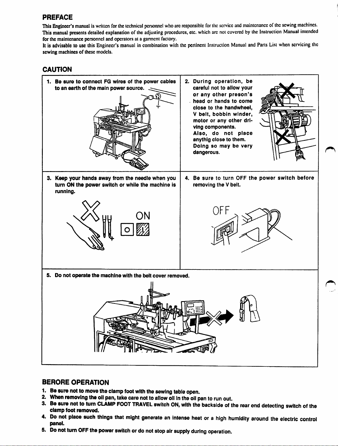
PREFACE
This
Engineer's
This
manual
for the maintenance personnel and operators at a ganneni factory.
Itis
advisabletouse
sewing machinesofthese models.
CAUTION
1.
Be
toanearthofthe
manualiswriitcn
presents
suretoconnect
detailed
this
for
ihe
explanationofthe
Engineer's
main
manualincombination
FG
wiresofthe
power
technical
source.
personnel
adjusting
power
cables
who
procedures,
with
are
responsible
the
pertinent
2.
for
the
service
etc.
which
arc
not
coveredbythe
Instruction
During
careful not to allow
or
head
closetothe
V
motororany
ving
Also,
anythig
Doing
dangerous.
operation,
any
other
or
hands
belt,
bobbin
components.
do
closetothem.
so
handwheel,
not
may
and
maintenanceofthe
Manual
and
be
your
preson's
to
come
winder,
other
dri-
place
be
very
Instruction
Parts
List
sewing
Manual
when
machines.
intended
servicing
the
3. Keep
turnONthe
running.
5. Do
not
your
operate
hands
power
away from
switch or while
the
machine
the
with
needle
the
ON
m
the
belt
when you
machine Is
cover
removed.
4. Be
removing
suretoturn
theVbeit.
OFF
the
power
switch
before
BERORE
1. Besure notto
When
Be
clamp
Do
panel.
Do
OPERATION
removing
sure
nottoturn
foot removed.
not
place
notturn
OFF
move
the
such
the
the
clamp
oil
pan,
take
CLAMP
things
power
FOOT
that
switch
foot
with
the
carenotto
TRAVEL
might
switch
generateanIntense
ordo notstopair
sewing
allow
table
oilInthe
ON,
with
supply
open.
oil
pantorun
the
backsideofthe
heat
during
ora
out.
high
operation.
rear
humidity
end
detecting
around
the
electric
switchofthe
control
Page 3
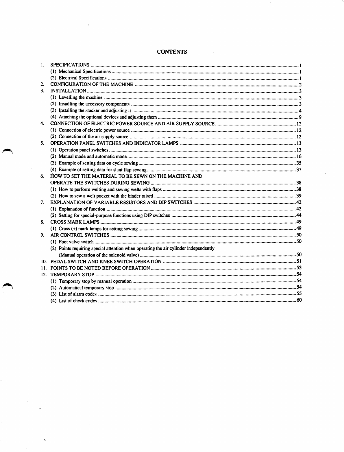
CONTENTS
1.
SPECIFICATIONS
(1) Mechanical Specifications 1
(2) Electrical Specifications I
2.
CONFIGURATIONOFTHE
3.
INSTALLATION
MACHINE
(1) Levelling the machine 3
(2) Installingthe accessorycomponents 3
(3) Installing the stacker and adjusting it 4
(4) Attaching the optional devices and adjusting them 9
4.
CONNECTIONOFELECTRIC
POWER
SOURCE
AND
AIR
SUPPLY
SOURCE
(1) Connection of electric power source 12
(2) Connection of the air supply source 12
5.
OPERATION
PANEL
SWITCHES
AND
INDICATOR
LAMPS
(1) Operation panel switches 13
(2) Manual
mode
and automatic
mode
(3) Example ofsetting data on cycle sewing 35
(4) Example of setting data for slant flap sewing 37
6.
HOWTOSET
OPERATE
THE
THE
MATERIALTOBE
SWITCHES
DURING
SEWNONTHE
SEWING
MACHINE
AND
(1) How to perform welting and sewing welts with flaps 38
(2) How to sew a welt pocket with the binder raised 39
7.
EXPLANATION
OF
VARIABLE
RESISTORS
AND
DIP
SWITCHES
(1) Explanation of function 42
(2) Setting for special-purpose functions using DIP switches 44
8.
CROSS
(I)
9.
MARK
LAMPS
Crass (+) mark lampsfor settingsewing 49
AIR
CONTROL
SWITCHES
(1) Foot valve switch 50
(2) Pointsrequiringspecial attentionwhen operatingthe air cylinder independently
(Manual
10.
PEDAL
11.
POINTSTOBE
12.
TEMPORARY
(1)
Temporary
(2)
Automatical
operationof thesolenoidvalve) 50
SWITCH
AND
KNEE
NOTED
STOP
BEFORE
.stopbymanual
temporary
.stop
SWITCH
OPERATION
operation
OPERATION
(3) List of alarm codes 55
(4) Listof check codes 60
1
2
3
12
13
16
38
42
49
50
51
53
54
54
54
Page 4
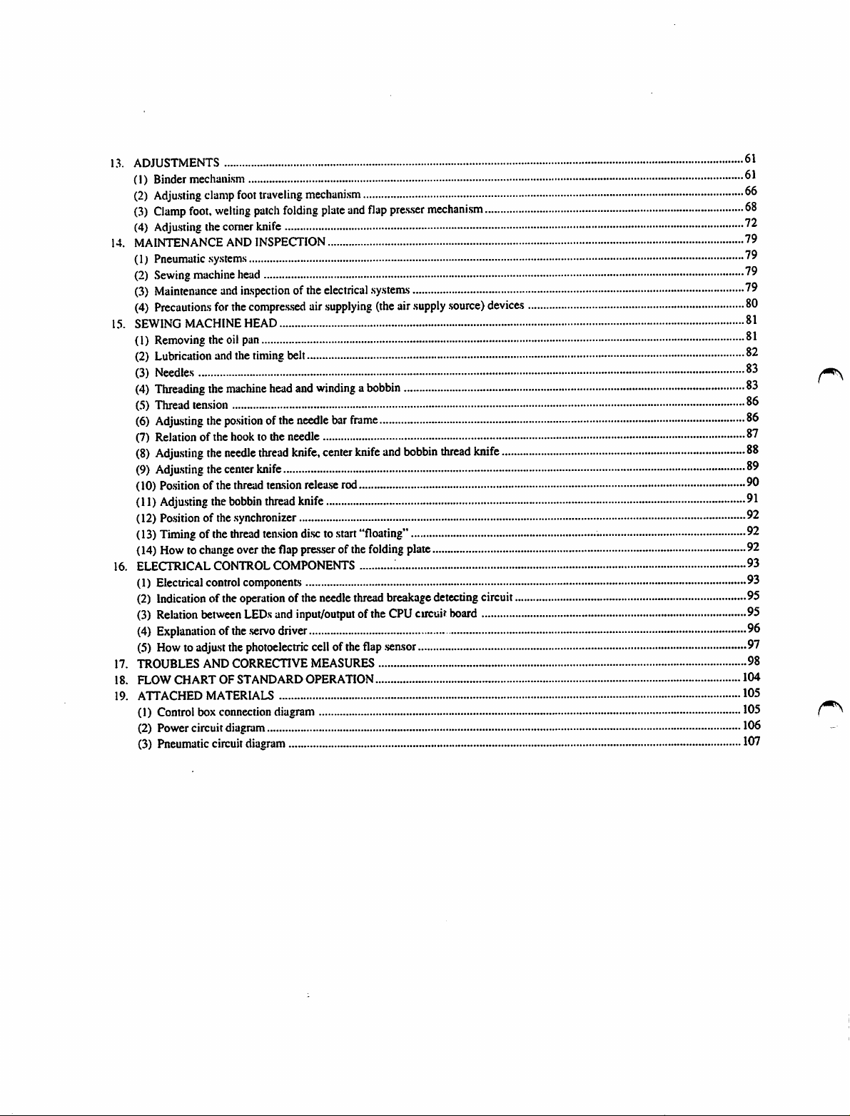
13.
ADJUSTMENTS
(1)
Binder
(2)
Adju.siing
(3)
Clamp
(4) Adju.sting the comer knife
14.
MAINTENANCE
(1)
Pneumatic
(2)
Sewing
(3)
Maintenance
(4)
Precautions
15.
SEWING
(1)
Removing
(2)
Lubrication
(3)
Needles
(4)
Threading
(5)
Thread
(6)
Adjasting
(7)
Relationofthe
(8)
Adju.siing
(9)
Adjasting
(10) Po.sition of the thread tension relea.serod
(11)
Adjasting
(12)
Po.sitionofthe
(13)
Timingofthe
(14)
Howtochange
16. ELECTRICAL CONTROLCOMPONENTS 93
(1)
Electrical
(2)
Indicationofthe
(3)
Relation
(4)
Explanationofthe
(5)
Howtoadjast
17. TROUBLESANDCORRECTIVE
18. FLOW CHART OF STANDARD OPERATION 104
19. ATTACHED MATERIALS 105
(1)
Control
(2)
Power
(3)
Pneumatic
clamp
foot,
welting
AND
.sy.stems
machine
and
for
the
MACHINE
the
oil
and
the
machine
tension
the
po.sitionofthe
hooktothe
the
needle
the
center
the
bobbin
.synchronizer
thread
control
between
the
box
connection
circuit
diagram
circuit
foot
traveling
patch
folding
INSPECTION
head
inspectionofthe
compre.s.sed
HEAD
pan
the
timing
belt
head
and
needle
needle
thread
knife,
knife
thread
knife
tension
over
the
flap
components
operation
LEDs
photoelectric
diagram
.servo
ofthe
and
input/output
driver
diagram
mechani.sm
plate
and
electrical
air
.supplying
windingabobbin
bar
frame
center
knife
di.scto.start
pre.sserofthe
cellofthe
MEASURES
needle
"floating"
thread
ofthe
flap
flap
pre.s.ser
.sy.stem.s
(the
air
and
bobbin
folding
plate
breakage
CPU
.sensor
mechanism
supply
.source)
thread
detecting
circuit
board
devices
knife
circuit
66
68
79
79
79
79
80
81
81
82
83
83
86
86
87
88
89
91
92
92
92
93
95
95
96
97
98
105
106
107
Page 5
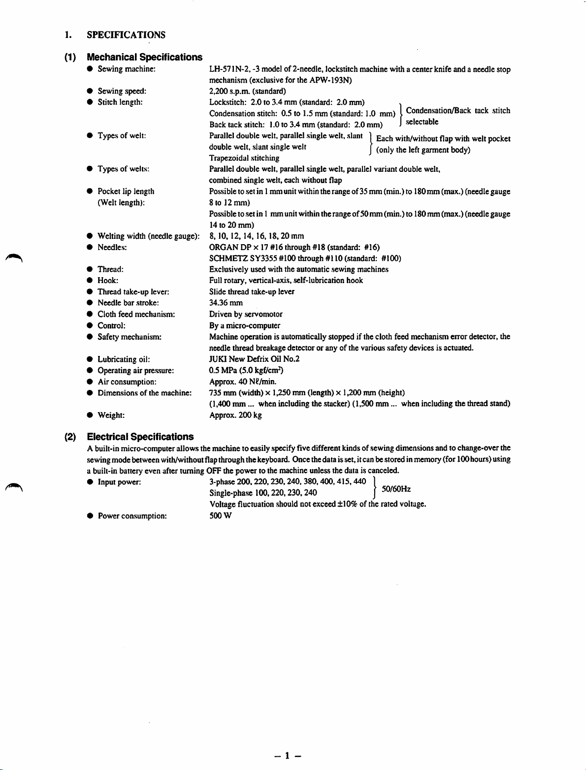
1.
SPECIFICATIONS
(1) Mechanical
• Sewing muchine:
• Sewing speed:
• Stitch length:
• Types of welt:
•
Typesofwelts:
• Pocket lip length
(Welt length):
• Welting width (needle gauge):
•
Needles:
•
Thread:
•
Hook:
• Thread take-up lever:
•
Needle
•
Cloth
•
Control:
• Safety mechanism:
• Lubricating oil:
• Operating air pressure:
• Air consumption:
•
Dimeasionsofthe
• Weight:
Specifications
bar
stroke:
feed
mechanism:
machine:
LH-571N-2, -3 modelof 2-needle, lockstitch machine with a center knife and a needle stop
mechanism (exclusive for the APW-193N)
2,200 s.p.m. (standard)
Lockstitch:
Conden-sation
Back
Parallel
double
Trapezoidal stitching
Parallel double welt, parallel .single welt, parallel variant double welt,
combined .singlewelt, each without flap
Po.s.sible
8 to 12
Po.s.sible
14 to 20
8.10.12,
ORGAN DP X 17 #16 through #18 (standard: #16)
SCHMETZ SY3355 #100 through #110 (.standard: #100)
Exclusively used with the automatic .sewing machines
Fullrotary, vertical-axis, .self-lubrication hook
Slide thread take-up lever
34.36
Driven by .servomotor
Bya micro-computer
Machineoperation is automaticallystopped if the cloth feed mechanismerror detector, the
needle thread breakage detector or any of the varioas safety devices is actuated.
JUKI
0.5MPa(5.0
Approx. 40 Nd/min.
735 mm (width) x 1,250 mm (length) x 1,200 mm (height)
(1,400
Approx. 200 kg
2.0to3.4
tack
stitch:
double
welt,
slant
to.setin 1mm unit withintherange of 35
mm)
to.setin 1 mm unitwithin the range of50 mm (min.) to 180mm (max.) (needle gauge
mm)
14,16,18,20
mm
New
Defrix
mm...
mm (standard: 2.0 mm) x
.stitch:
0.5to1.5mm(.standard:
1.0to3.4mm(standard:
welt,
parallel
single
single
welt
mm
Oil
No.2
kgf/cm-0
when including the .stacker)(1,500
welt,
slant1gach
2.0
1.0
mm)ICondensation/Back
mm)J.selectable
with/without
j
mm(min.)to
mm...
when including the thread stand)
flap
with
garment
180mm (max.) (needlegauge
body)
tack
welt
.stitch
pocket
(2) Electrical
Abuilt-inmicro-computerallowsthe machineto easily
sewingmode
a built-in battery even after turning OFF the power to the machine
•
Input
• Power coasumption: 500 W
Specifications
between
power:
with/withoutflapthroughthe
3-phase
200,220,230,240,
Single-phase
Voltagefluctuation
100,220,230,240
.specify
keyboard.
.should
fivedifferentkindsof
Oncethedataisset,itcanbestoredin
unle.ss
the data is canceled.
380,400,415,440
notexceed±10%of the rated voltage.
.sewing
dimensionsand tochange-overthe
|
J
50/60Hz
memory
(for100hours)using
- 1 -
Page 6

2.
CONnCURATION
The APW-I93N consists mainly of the following units;
O
Frame
and
(Frame,sewing table,covers, foot switch etc.)
®
Clamp
® Comer knife unit
0
Binder
0
Pneumatic
0 Stacker unit
0
Sewing
0 Electriccontrolunit(Control box)
O Oil
pan
0
Operation
0 Powerswitch
structural
foot
unit
unit
(Binder
control
machine
panel
OF
THE
components
and
feed
components
unit
head
MACHINE
mechanism
(Pneumatic
andits
control
driving
devices
components)
and
piping.s)
Fig. 1
With
this
machine,
place andoperating the switches on the operation panel.
youcando
desired
welting
work
simplybysetting
- 2 -
materials
(garment
body,
interlining
piece,
welting
patch
etc.)
in
Page 7
3.
INSTALLATION
(1) Levelling
(2) Instaliing
the
machine
the
accessory
Fig. 2
components
Yellow
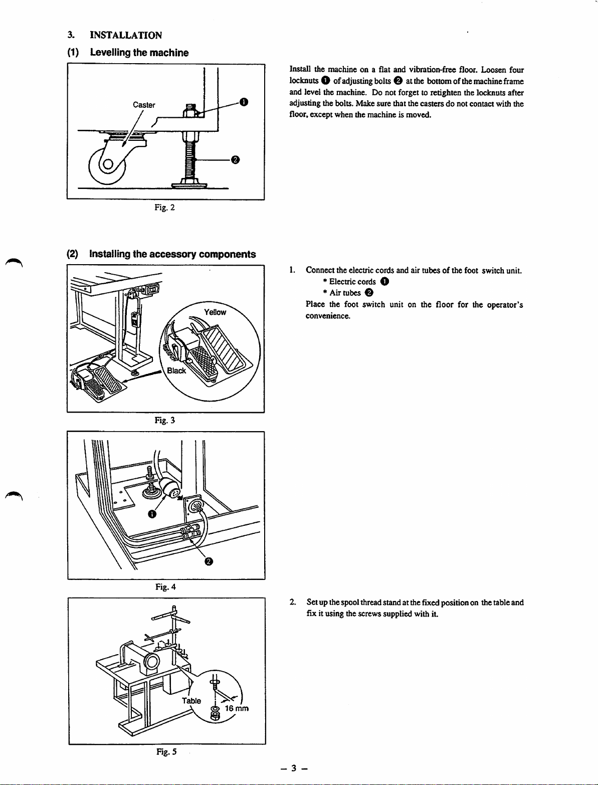
Install
the
locknuts
machineona
O of
adjusting
flat
bolts
and
vibration-fiee
O at
the
bottom
floor.
ofthe
Loosen
machine
four
frame
and level the machine. Do not forget to retighten the locknuts after
adjusting the bolts. Make sure that the casters do not contact with the
floor, except when the machine is moved.
1.
Connect
the
electric
cords
and
air
tubesofthe
foot
switch
unit.
^ Electriccords O
*
Air
tubes
Place the foot switch unit on the floor for the operator's
convenience.
Black
2. Set upthespoolthreadstandat thefixedpositionon the tableand
fix it using thescrewssupplied with it.
Table
Rg.5
1
16
mm
- 3 -
Page 8
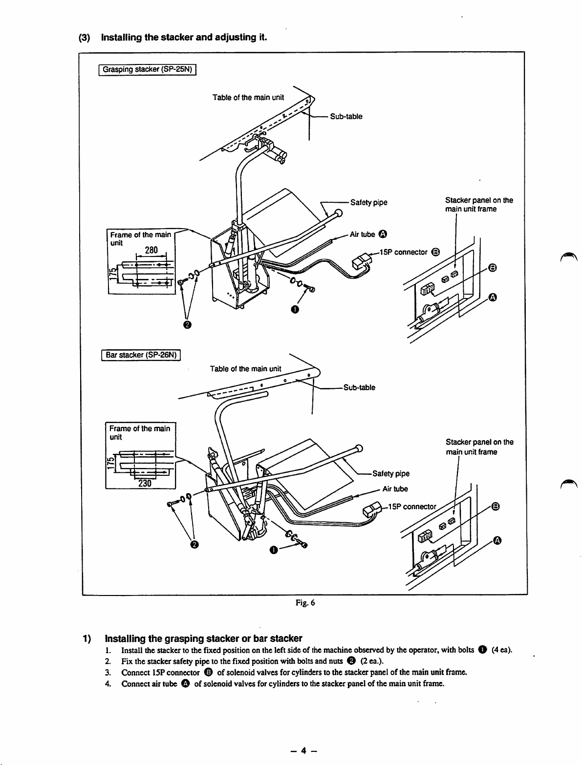
(3)
Installing
Grasping stacker (SP-25N)
the
stacker
and
adjusting
it.
Frameofthe
unit
Barstacker
main
280
(SP-26N)
Tableofthe
|
Tableofthe
main
main
unit
unit
Sub-table
Safety pipe
Air
tube O
15P connector (2)
Stacker
main
unit
panel
frame
on the
Frameofthe
unit
230
1) Installing
1.
Install
2. Fix
3.
4.
the
Connect
Connect
main
the
grasping
the
stacker
stacker
safety
15P
connector
airtube O of
stackerorbar
tothe
fixed
pipe
® of
solenoid
positiononthe
tothe
Hxed
solenoid
valves
stacker
position
valves
for
cylinders
left
sideofthe
with
for
Fig. 6
bolts
and
cylinders
tothe
•Sut)-table
machine
observedbythe
nutsO(2ea.).
tothe
stacker
stacker
panel
Safety pipe
Air
15P
panel
ofthe
ofthe
main
tube
connector
operator,
main
unit
unit
frame.
Stacker
main
with
frame.
panelonthe
unit
bolts
frame
O (4
ea).
- 4 -
Page 9
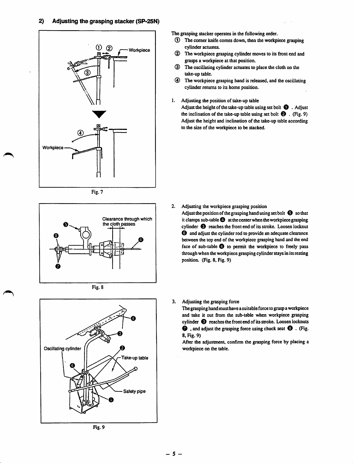
2) Adjusting
Workpiece
>-ii
the
r (D
grasping
Fig. 7
stacker
(SP-25N)
j—Workpiece
The grasping stacker operates in the following order.
®
The
comer
knife
comes
down,
then
the
workpiece
cylinder actuates.
(D The
(D
(i)
1.
workpiece
gra^s
The
oscillating
take-up table.
The
workpiece
cylinder returns to its home position.
Adjusting the position of take-up table
Adjust
the
the
inclination
Adjust the height and inclination of the take-up table according
to the
size
grasping
a workpiece at that position.
cylinder
grasping
height
ofthe
ofthe
of the workpiece to be stacked.
cylinder
actuatestoplace
handisreleased,
take-up
table
take-up
table
moves
using
using
.set
toits
front
the
clothonthe
and
the
setbolt O •
bolt
0 .
grasping
end
and
oscillating
Adjust
(Fig.
9)
Oscillating cylinder
Fig. 8
Clearance
the
cloth
through which
passes
o
Take-up table
2.
Adjusting the workpiece grasping position
Adjust
the
positionofthe
it
clamps
sub-table
cylinder0reaches
0 and
adjust
the
between the top end of the workpiece grasping hand and the end
face
of sub-table O to
throughwhen the workpiecegrasping cylinder staysin itsresting
position. (Fig. 8, Fig. 9)
3.
Adjusting the grasping force
Thegrasping handmusthavea suitableforce tograsp aworkpiece
and take it out from the sub-table when workpiece grasping
cylinder0reaches
0 ,
and
adjust
8, Fig. 9)
After the adjustment, confirm the grasping force by placing a
workpiece on the table.
O atthe
cylinder
the
grasping
grasping
the
front
the
hand
center
endofits
rodto
provideanadequate
permit
the
front
endofits
force
using
set
bolt
when
the
workpiece
stroke.
Loosen
workpiecetofreely
stroke.
Loosen
using
chuck
seat
0 so
grasping
locknut
clearance
pass
lockouts
0 .
(Hg.
that
Safety
pipe
Fig. 9
- 5 -
Page 10
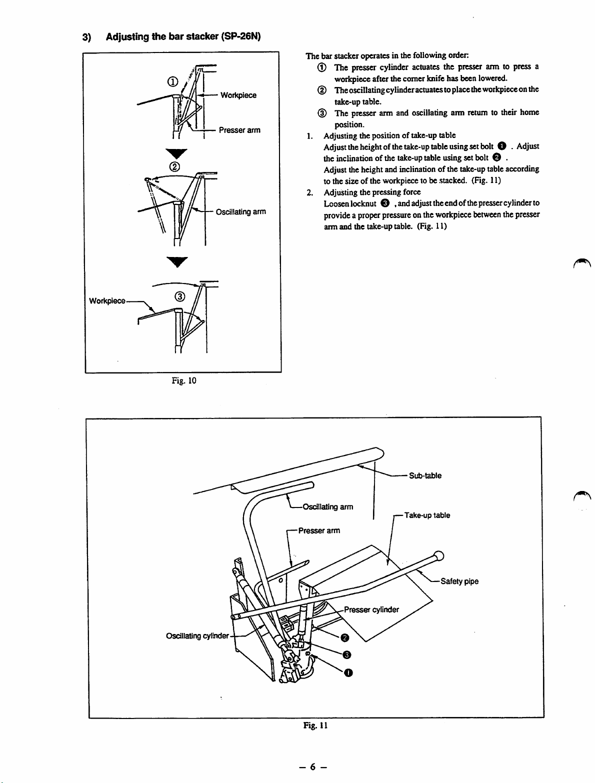
3) Adjusting
Workpiece
the
bar
stacker (SP-26N)
Presser
Oscillating
Workpiece
arm
arm
The bar stacker operates in the followingorder:
(l) The
(D Theoscillatingcylinder
(D The
1. Adjusting the position of take-up table
2. AdjuSdng the pressing force
presser
workpiece
take-up table.
position.
Adjust
the
the
inclinadon
cylinder
afterthecomerknifehasbeen
presser
arm and
heightofthe
ofthe
actuates
actuates
oscillating
take-up
take-up
table
table
the
toplacethe
using
using
Adjusttheheightandinclination of the
to the size of the workpieceto be
.stacked.
presser
arm
take-up
Loosenlockout O .andadjusttheendofthe
provide
a properpressure onthe
arm and the take-up table. (Fig. 11)
workpiece
arm to
lowered.
workpiece
returntotheir
set
bolt
O •
set
bolt
O .
tableaccording
(Fig. 11)
presser
between
press
onthe
home
Adjust
cylinderto
thepresser
a
Fig. 10
Oscillating cylinder
Osdilating
Presser
arm
arm
Presser
0
cylinder
•
Sub-table
-Take-up
table
Safety
pipe
Fig. 11
- 6 -
Page 11

4) Attaching
1. Attach the roller stacker on the left-hand side face of the main unit frame, and fix it with three screws taking care to set the
roller in parallel to the main unit table.
Roller
Main
stacker
the
unit
attaching
roller
frame
stacker
position
PJ304040505
(SP-36N)
^6
tube
2.
Pa.ss
theairtube O for
connector©for
© in
Fig.
3.
Connect
illustrated in the figure below.
air
shown
tube
roller
above
O .
Fig. 12
roller
oscillating
oscillating
inthe
written
15P
connector©and2Pconnector©respectively
Stackerpanel on the
main
unit
cylinder
frame
solenoid
order.
and
valve,
outputcablefordrivingroller,theupperdetection
the
motor
power
cable
* Whenattachingtherollerstackerto themachine, puta plug toone
side of the hole for quick-coupling
ofthe2P
connectorOthrough
tothe
stacker
panel
ofthe
joint
sen.sor
holes
main
cableofthe
® , ®
unit
frame
and
as
Fig. 13
- 7 -
Page 12
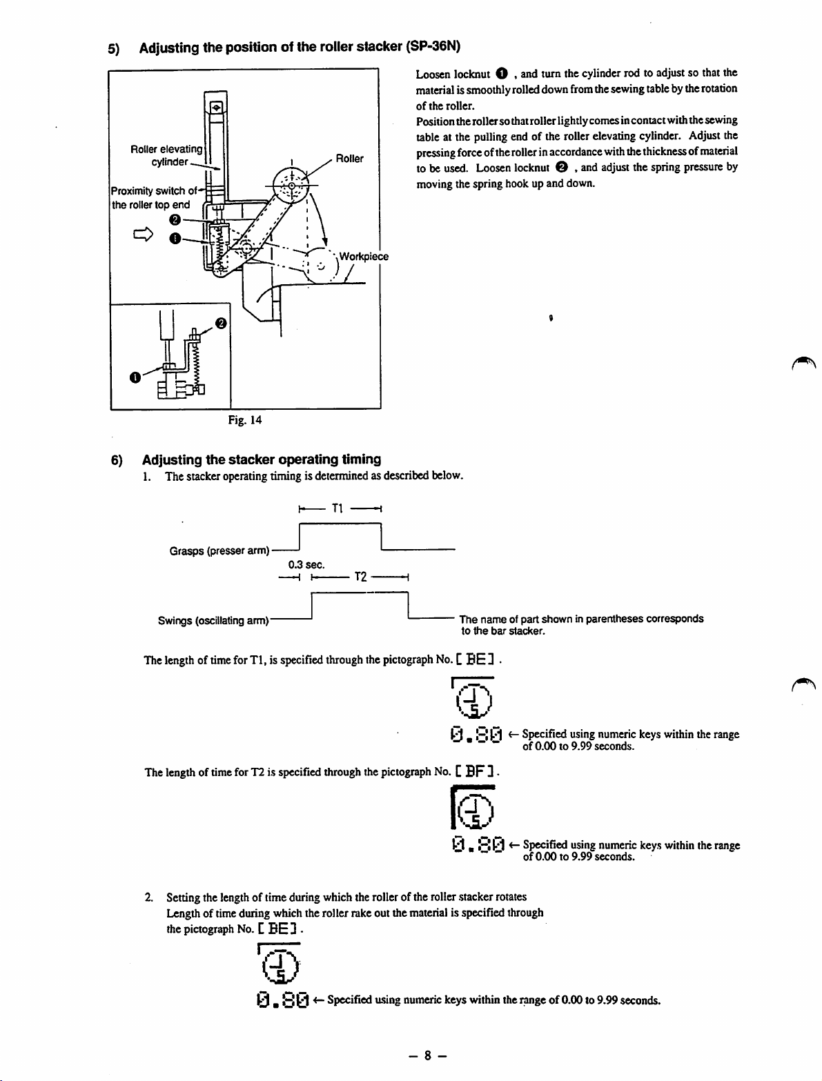
5) Adjusting the position of the rollerstacker
Roller
elevating
cylinder
Proximity switch of*'
the roller top
O
end
©-
0-
Fig. 14
Roller
\Workpiece
(SP-36N)
Loosenlockout O . end turn the cylinderrod to adjustso thatthe
material
issmoothlyrolleddownfromthesewingtablebythe
of
the
roller.
Positiontherollersothatroller lightlycomesincontact withthe sewing
tableat the
pressing
to be
moving the spring hook up and down.
force
used.
pulling
end of the rollerelevating cylinder. Adjustthe
ofthe
rollerinaccordance
Loosen
locknut
© , andadjustthe spring
with
the
thicknessofmaterial
rotation
pressure
by
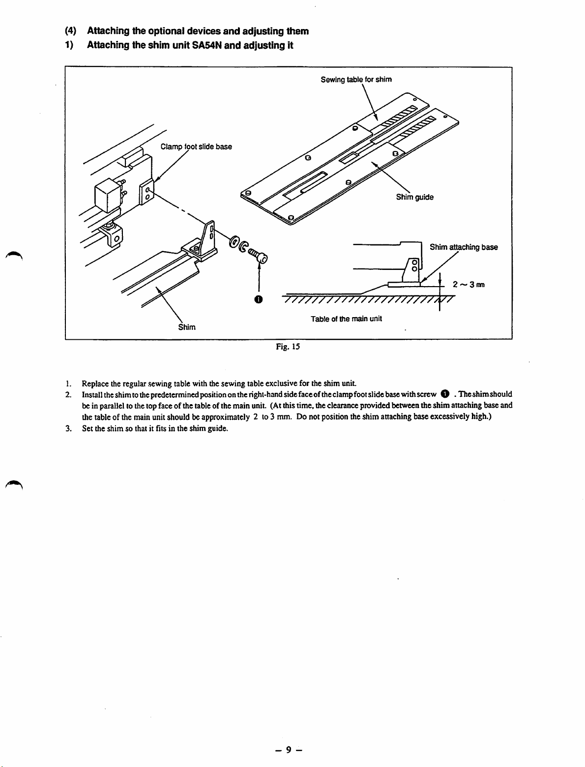
6)
Adjusting
1. The stackeroperatingtiming is determinedas described below.
Swings (oscillating
The
The
the
Grasps
(presser arm) •
lengthoftime
lengthoftime
stacker
arm)'
for
Tl, is
for
T2is
operating
0.3
sec.
-H
I T2
specified
specified
timing
T1
through
through
the
pictograph
the
pictograph
The name of part shown in parenthesescorresponds
to
the
bar
stacker.
No.
CBE D
y.y0
No.CBF
ti.yy
*" ~ ~ of 0.00 to 9.99 seconds.
~ *"
3
<-
Specified
of
0.00to9.99
<-
specified
using
using
numeric
seconds.
numeric
keys
keys
within
within
the
the
range
range
2. Setting the lengthof time during which the rollerof the roller.stackerrotates
Lengthof timeduring which the roller rake out the materialis specifiedthrough
the
pictograph
No.CBE3 •
Ci)
ir- Specified u.sing numeric keys within the rangeof0.00 to 9.99 seconds.
- 8 -
Page 13
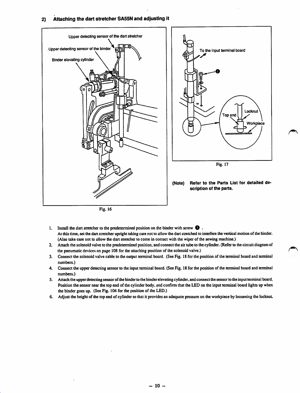
(4) Attaching
1) Attaching
the
the
optional
shim
unitSA54N
Clamp
devices
foot slide
base
and
and
adjusting
adjusting
them
It
Sewing
table
for
shim
Shim guide
Shim attaching
2 ~ 3
O
"7777777777777777777777/77
side
Tableofthe
faceofthe
position
Shim
Fig. 15
1. Replacetheregular
2.
Install
the
shimtothe
beinparallelto thetopface of thetableof the main unit. (Atthistime,theclearanceprovidedbetweentheshim attachingbase and
thetableof themainunitshould be
3. Set the shim so that it fits in the shim guide.
.sewing
table withthesewing tableexclusivefor theshim unit.
predetermined
positiononthe
approximately
right-hand
2 to3 mm. Donot
main
unit
clamp
foot
slide
base
with
screw
O •
theshimattaching baseexcessively high.)
The
base
mm
shim
should
- 9 -
Page 14
2) Attaching the dart stretcher
Upperdetectingsensor ofthe dart stretcher
SA55N
and adjusting it
Upperdetecting sensor ofthe binder '
Binder
elevating
cylinder
\
To
(Note) Refer to
scriptionofthe
the
input terminal
Fig. 17
the
Parts
board
Locknut
Workpiece
List for detailed de
parts.
Fig. 16
Install
the
dart
stretchertothe
Atthis time, setthedan stretcheruprighttakingcarenotto allowthedan stretchedto interferetheverticalmotionof the binder.
(Also take care not to allow the
Attachthe solenoidvalveto the predetermined position,andconnecttheairtubeto the cylinder.(Referto thecircuitdiagramof
thepneumatic
Connect the solenoidvalve cable to the outputterminalboard. (SeeFig. 18for the positionof theterminalboardand terminal
3.
numbers.)
4.
Cormectthe upperdetectingsensor to the inputterminal board.(SeeFig. 18for the positionof the terminalboard and terminal
numbers.)
Attachthe upperdetectingsensor ofthe bindertothe binderelevatingcylinder,andconnectthesensor totheinputterminalboard.
Position the sensor near the top end of the cylinderbody,and confirm that the LED on the input terminal board lights upwhen
the binder goes up. (SeeFig. 104for the positionof the LED.)
Adjust the height of the top end of cylinderso that it provides an adequate pressureon the workpiecebylooseningthe locknut
6.
device.s
predetermined
dan
positiononthe
stretcher to come in contact with the wiper of the sewing machine.)
onpage 108for theattaching
binder
po.sition
of thesolenoidvalve.)
with
screw
O •
-
10
-
Page 15
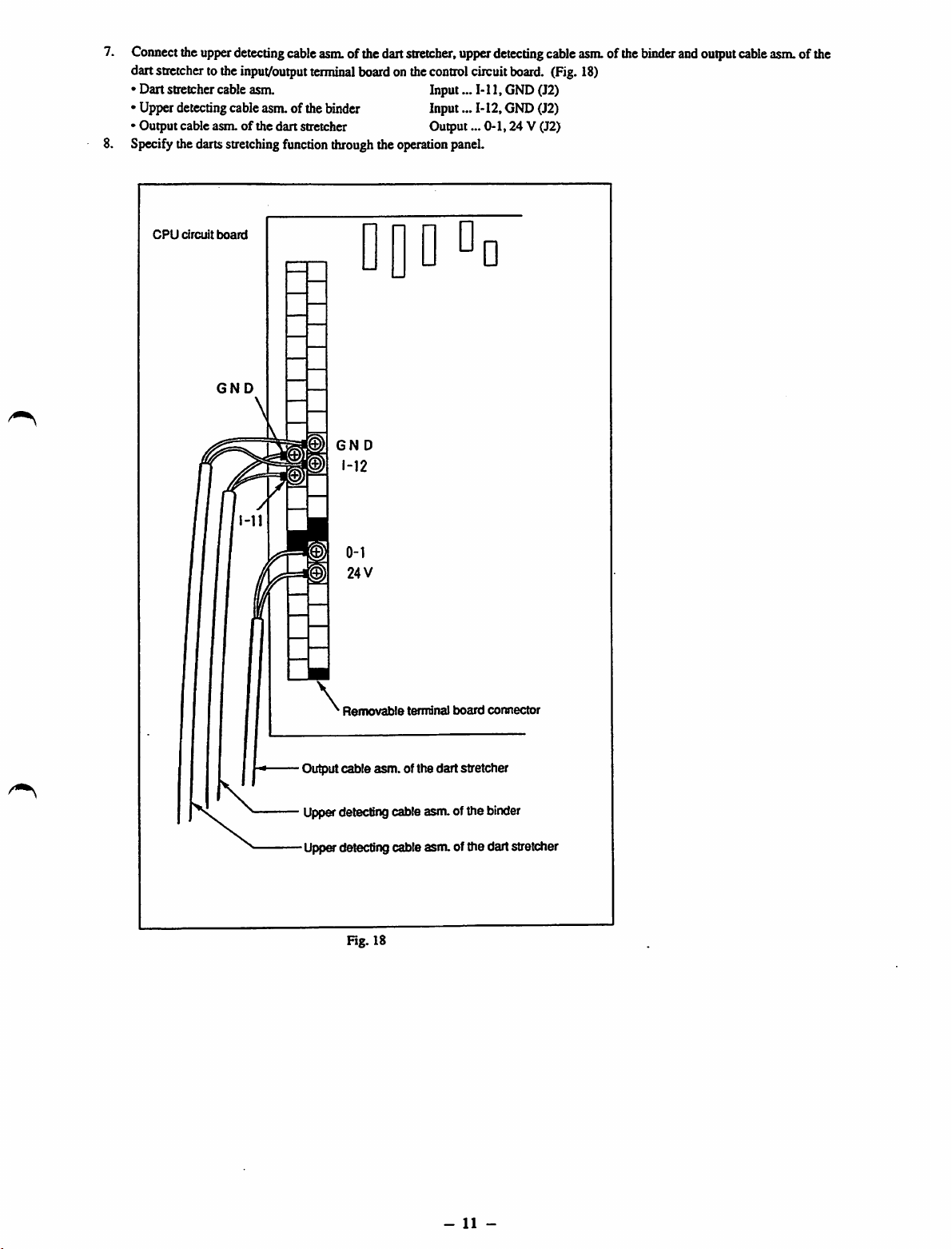
7.
Connect
dartstretcher to the
• Dart stretchercableasm. Input...
• Upper detectingcable asm.of the binder Input...
• Output cable asm. of the dart stretcher Output...
Specifythedartsstretchingfunctionthroughthe operation panel.
CPU
the
circuit
upper
board
detecting
input/output
cable
asm.
terminal
ofthedart
boardonthe
stretcher,
DQDDd
GND
GN
D
control
upper
circuit
Ml,
M2,
detecting
board.
GND(J2)
GND(J2)
0-1,24
cable
V (J2)
asm.
(Fig.18)
ofthe
binder
and
output
cable
asm.ofthe
Removable
Output
cable
\
Upperdetectingcable asm.of the binder
Upp&detecting cable asm. of the dart stretcher
Fig. 18
terminal
asm.
of the dart stretcher
board
connector
-
11
-
Page 16

4.
CONNECTIONOFELECTRIC
POWER
(1)Connection of electric power source
Connect
the
power
supply
cordofthe
sure that the sewingmachine rotatesin thecorrectdirection.
[Rotating direction]
Turn
the
handwheel
directionofthe
from
the
handwhecl's
wires
(R.S.T.).
[Precaution in the electric connection]
1. Connect the ground wire to the earth without exception.
2. Quality of power
• Voltagefluctuation
• Rapid change of power voltagemaystop the machine.
• Surge
(2)
Connectionofthe
toletthe
handwheel.
Whenthewire
side)tostop
currentorelectromagnetic
air
supply
Air
operation
needle
down
the
mu.st
notexceed± 10%of the ratedvoltage.
paneltothe
toits
connectioniscorrect,
needle
inits
inductioninpower
source
cock
SOURCE
AND
power
lowest
dead
point
and
the
highest
dead
position.Ifnot,
may
Airpressure adjusting knob
AIR
SUPPLY
source
outlet
turn
handwheel
leadthe
SOURCE
(R.S.T.E.).
the
power
willrotateinthe
alternate
machinetomalfunction.
supply
When
switch
counterclockwise
the
connectionoftwo
connecting
"ON"as
you
the
lead
watch
direction
wires
wires,
make
the
rotating
(viewed
outofthree
Airsupply
Air
pressure
gauge
/
Airniter regulator
\ ^
Fig. 19
1. Securely connect the air supply
2.
Open
theaircockand
knob.
[Precautions for the air supply source]
Referto the article[(4) Precautionsforthecompressedairsupplying(theairsupplysource)devices]ofInspectionandmaintenance.
(Page 80)
adjust
theair
ho.se
(1/4")to the air cock locatedon the rear face of the machine.
pressure
sothattheair
pressure
gauge
indicates
S.O
kgf/cnF
(0.S
MPa)
bytheair
pre.ssure
adjusting
-
12
-
Page 17
5.
(1)
OPERATION
Operation
PANEL
panel
SWITCHES
switches
AND
INDICATOR
LAMPS
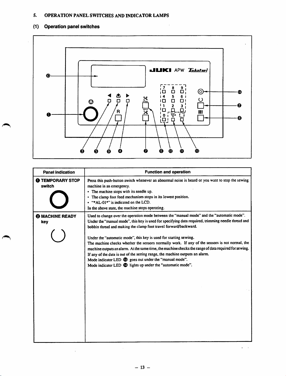
Panel
indication
O TEMPORARY
switch
STOP
o
0 MACHINEREADY
key
kJIIJIICI
APW
rL.Pj
T&kafort
T1
0 e o o 0 0 0
Function
Press this push-button switchwheneveran abnormalnoiseis heard or you wanttostop thesewing
machine in an emergency.
• The machinestops with its needle up.
• The clampfootfeed mechanism stops in its lowestposition.
•
"♦AL-01*"
In the above state, the machine stops operating.
Usedto
Under the"manualmode", this key is
bobbin thread and
change
is
indicatedonthe
overthe
operation
nnaking
LCD.
mode
u.sed
theclamp foot travel forward/backward.
and
operation
between
the"manualmode" andthe"automatic
for specifyingdata required, trimmingneedlethreadand
-0
0
©
mode".
O
Under the "automatic mode", this key is used for starting .sewing.
The machine checks whether the .sensors normally work. If anyofthe sensors is not normal, the
machine
outputsanalarm.Atthe
If anyof thedata isoutofthe
Mode
Mode
indicator
indicator
LED0goes
LED0lightsupunder
.same
.setting
out
-
13
time,
range,the
under
-
the
the
"manual
the
"automatic
machine
machine
checks
outputsan
mode".
mode".
the
range
alarm.
ofdata
required
for
sewing.
Page 18
Panel
indication
Function
and
operation
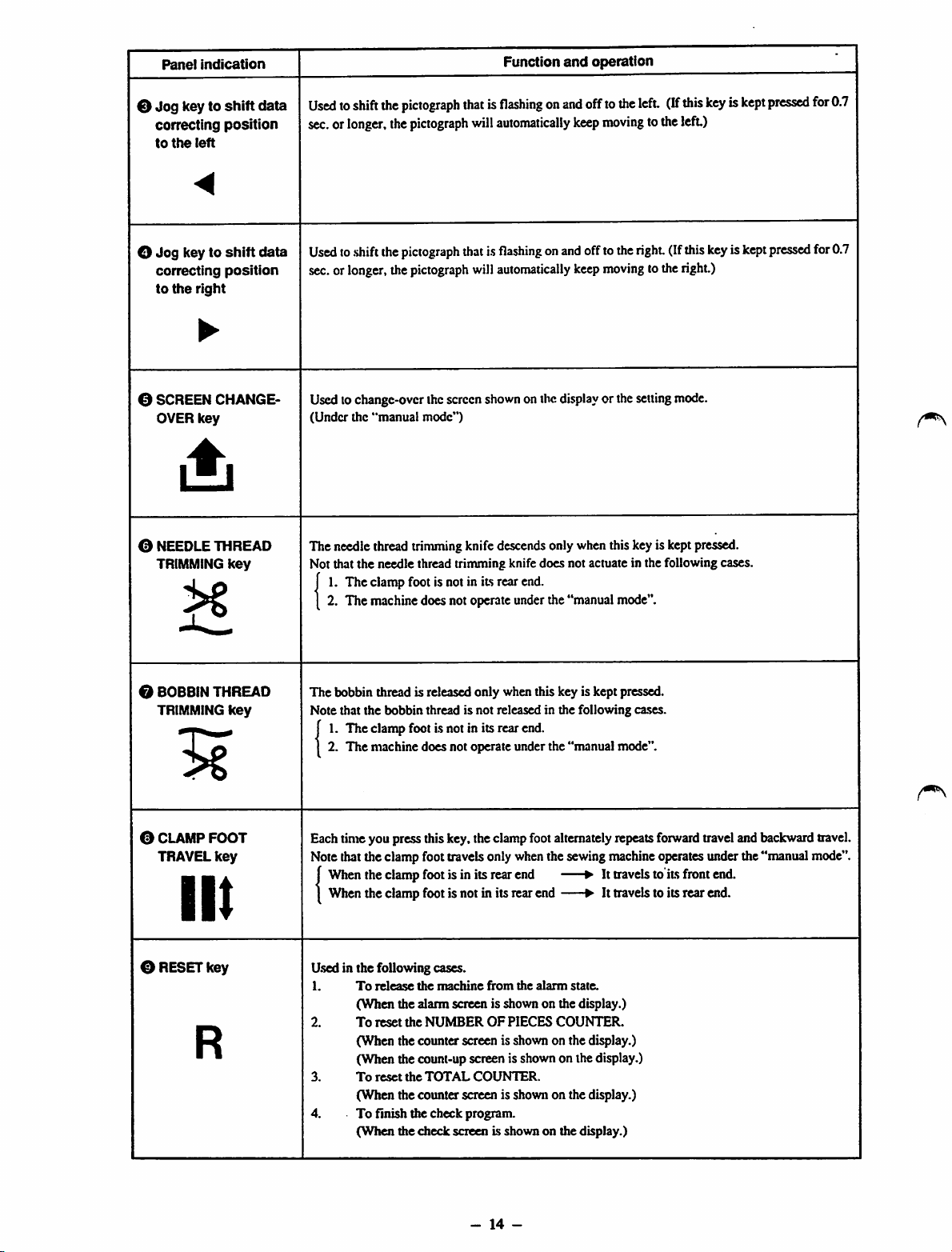
0
Jog
key to
shift
data
correcting
to
the
position
left
<
O
Jog
key to
shift
data
correcting
to
the
position
right
•
0 SCREEN CHANGE
OVER
key
0 NEEDLE THREAD
TRIMMING
key
Usedtoshift
sec.orlonger,
Used
sec.or
Usedtochange-over thescreen
(Under
The needle thread trimmingknife descendsonly whenthiskeyis keptpressed.
Not that the needle thread trinruningknife does not actuate in the following cases,
f1.The
[ 2. The
the
toshiftthe
longer,
the
"manual
clamp
machine
pictograph
the
pictograph
pictograph
the
pictograph
mode")
footisnotinits
does
not
thatisflashingonand
will
automatically
thatisflashingonand
will
automatically
shown
onthe
display
rear
end.
operate
under
the
"manual
offto
the
left.
keep
moving
totheleft)
offtotheright(If
keep
moving
tothe
or the
setting
mode".
(If
mode.
this
keyiskept
this
right.)
keyiskept
pressed
pressed
for
0.7
for0.7
0 BOBBINTHREAD
TRIMMING
0 CLAMP
TRAVEL
key
FOOT
key
III
0 RESETkey
R
The
bobbin thread is released only when this key is kept pressed.
Note that the bobbin thread is not released in the following cases.
J1.The
1 2.
Eachtimeyou pressthiskey.the clampfootalternately repeats
Notethatthe clamp foot travelsonly whenthe sewingmachine operatesunder the"manual mode".
j
1
Used in the following cases.
1.
2.
3.
4. To finish the check program.
clamp
footisnotinits
The
machine
When
the
When
the
To
(When
To
(When the counter screen is shown on the display.)
(When the count-up screen is shown on the display.)
To
(When the counter screen is shown on the display.)
(When
does
clamp
footisin
clamp
footisnotinits
release
the
machine
the alarm screen is shown on the display.)
reset
the
NUMBEROFPIECES
reset
the
TOTAL
the
check
rear
end.
not
operate
under
the
"manual
its
rear
end
rear
end
from
the
alarm
state.
COUNTER.
COUNTER.
screen is shownon the display.)
mode".
forward
•Ittravelstoits
• It
travelstoits
traveland backwardtravel.
front
end.
rear
end.
-
14
-
Page 19
Panel
indication
Function
and
operation
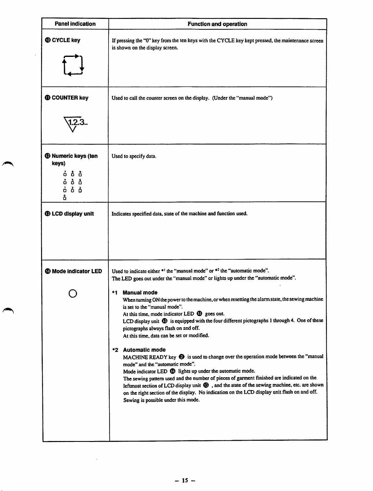
<D
CYCLE
key
n
<D
COUNTER
0 Nunteric keys (ten
keys)
®
LCD
key
5573..
• •
* i
• o
I 7
• •
0
•
display unit
If pressing the
is shown on the display screen.
Used to call the counter screen on the display. (Under the "manual mode")
Used to specify data.
Indicates
"0"
.specified
key from the ten keys with the CYCLE key kept pressed, the maintenance screen
data,state of the machineand function used.
(D
Mode
indicator
O
LED
Used
to indicate either *' the
The
LED
goesout
•^1
Manual
When
is
settothe
Atthis
LCD
pictographs
At this time, data can be set or modified.
*2
Automatic
MACHINE
mode"
Mode
The
sewing
leftmost
onthe
Sewingis possibleunder this mode.
under
mode
turningONthe
"manual
time,
mode
display
unit
always
mode
READY
and
the
"automatic
indicator
pattern
.sectionofLCD
right
section
"manual
the
"manual
power
tothe
mode".
indicator
® is
equipped
flash
onandoff.
key
O is
mode".
LED (D lightsup
used
andthe
display
ofthe
display.Noindication
mode"
or *-
the
"automatic
mode"
orlightsup
machine,orwhen
LED
O goesout.
with
the
usedtochange
under
theautomatic
four
le-setting
different
overthe
numberofpiecesofgarment
unit
® ,
and
the
state
onthe
mode".
under
the
"automatic
the
alarm
mode".
state,the
sewing
pictographs1through4.Oneofthese
operation
mode.
ofthe
LCD
mode
fini.shed
sewing
display
between
are
indicated
machine,
unit
flash
the
etc.
onand
machine
"manual
onthe
are
shown
off.
-
15
-
Page 20
(2) Manual
mode
and
automatic
mode
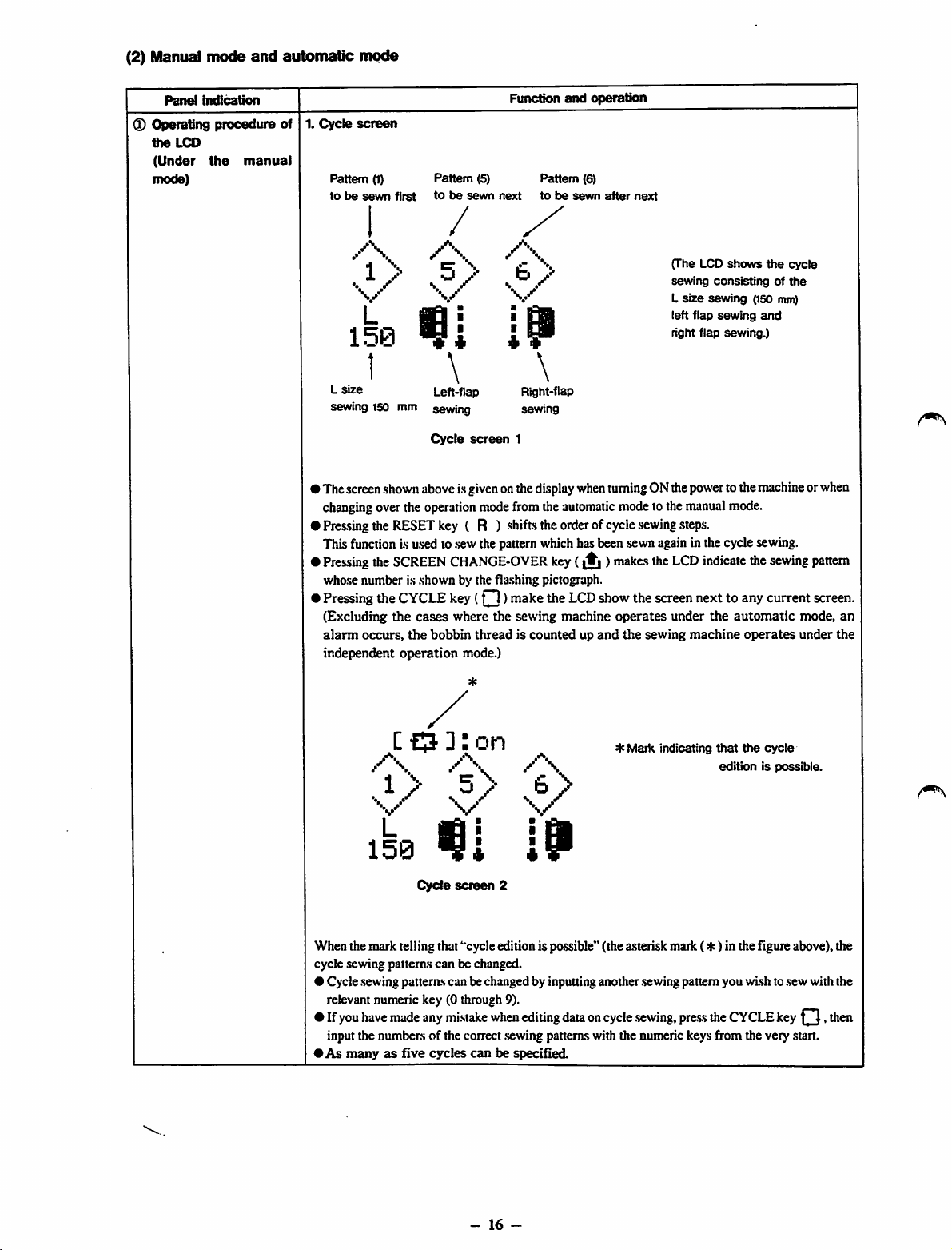
Panel
Operating
the
LCD
(Under
mode)
indication
procedure
the
manual
Funcdon
1.
Cycle
of
screen
Pattern
(1)
tobesewn
Pattern (5) Pattern (6)
first
tobesewn
next
and
tobesewn
operation
after
next
/
/\
'
.
V
L
m
I
I
150
I
L
size
sewing
150
mm
• ThescreenshownaboveisgivenonthedisplaywhenturningONthepowertothemachineorwhen
changing
•
Pressing
Thisfunctionis used to
•
Pressing
whose number is shown by the fla.shing pictograph.
•
Pressing
(Excluding
alarm
independent
overthe
theRESETkey ( R ) shiftstheorderofcycle
the
SCREEN
the
the
occurs,
Left-flap
sewing
Cycle
operation
CYCLE
cases
the
bobbin
operation
\
screen
.sew
CHANGE-OVER
key
where
mode.)
Right-flap
sewing
1
mode
fromthe
thepatternwhichhasbeen sewnagainin thecyclesewing.
(O )
make
the
threadiscountedupand
sewing
automatic
key
(|^)makes
the
LCD
machine
modetothe
show
operates
the
sewing
the
the
sewing
(The LCD
sewing
L
size
left
right flap
manual
.steps.
LCD
screen
under
shows
consistingofthe
sewing
flap
sewing
sewing.)
mode.
indicate
nexttoany
the
automatic
machine
operates
the
(ISO
and
the
sewing
current
mm)
cycle
mode,
under
pattern
screen.
an
the
CO
/"•s
*•!\ 'ir\
..1/
]:
on
b
s/
\ ^
*
Mark
indicating
that
the
cycle
editionispossible.
L
150
Cycle
screen
When the mark telling that "cycle edition is po.ssible"(the asterisk mark (4c) in the Hgure above), the
cycle .sewing patterns can be changed.
• Cycle .sewingpatternscan bechanged by inputting another .sewingpattern you wish to.sewwith the
relevant numeric key (0 through 9).
• If you have made any mi.stakewhen editing data on cycle .sewing,pre-ssthe CYCLEkey . then
input the numbers of the correct .sewingpatterns with the numeric keys from the very
•As
manyasfive
cycles
canbespecified
19
2
.start.
-
16
-
Page 21
Panel
indication
Function
2.
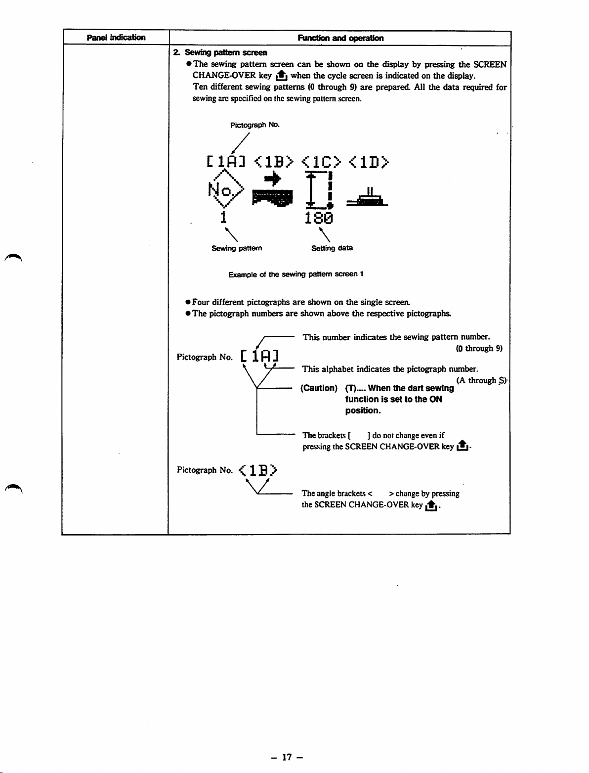
Sewing
pattern
screen
•
The
sewing pattern screen
CHANGE-OVER
Ten
different sewing
sewing arc spccillcd on the sewing pattern screen.
key^when
patterns
can
be shown on the display by pressing the SCREEN
the
(0 through 9}
and
operation
cycle
screenisindicatedonthe
are
prepared
All the
display.
data
required for
Clfl]
Sewing
>
Four
different
*The
pictograph
Pictograph
Pictograph
1
\
pattern
Exampleofthe
pictographs
numbers
No.
Clfll
No.
<1B>
/"
sewing
are
are
<1C>
u
180
\
Setting
pattern
shownonthe
shown
above
This
number
This
alphabet
(Caution)
<1D>
data
screen
(T)
function
position.
1
single
the
respective
indicates
indicates
When
screen.
the
the
the
is
settothe
pictographs.
sewing
pattern
pictograph
dart
sewing
ON
number.
(0
through
number.
(A
through
9)
S)
Pictograph
No.^1B>
The brackets [ ] do not change even if
pressing the SCREEN CHANGE-OVER key
The angle brackets < >change by pressing
the
SCREEN
CHANGE-OVER
key
^.
-
17
-
Page 22
Panel
Imfication
Function
b
iMJ
and
operation
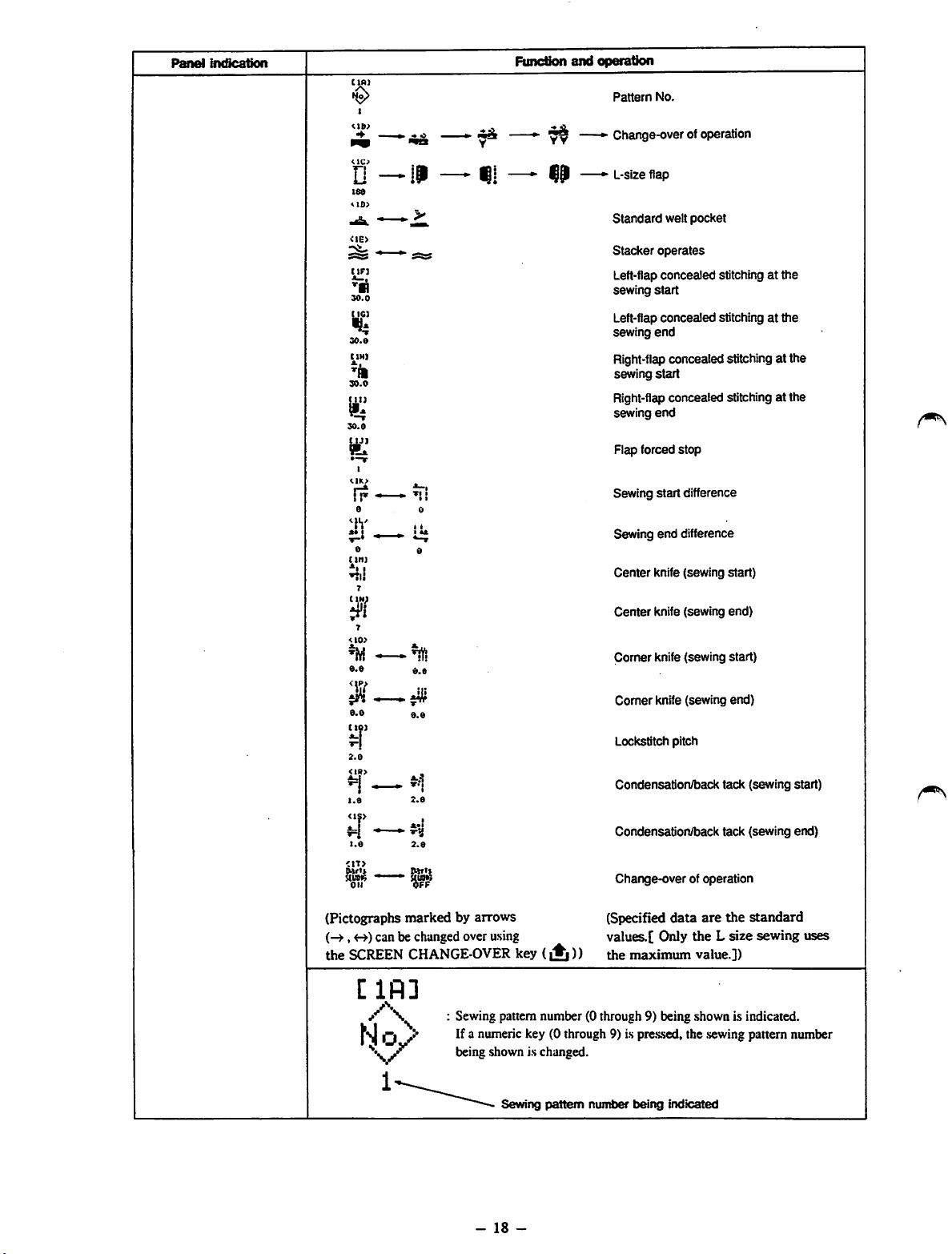
Pattern
No.
18«
<I0>
tin
30.0
Kg
30.0
CIH]
'/I
30.0
30.0
tyj
•-T
r?
a
^h'
a
titi]
ni!
Y
^ Change-over of operation
» L-size flap
Standard
Stacker
Left-flap
sewing
Left-flap
sewing
Right-flap
sewing
welt
pocket
operates
concealed
stitching at
start
concealed
stitchingatthe
end
concealedstitchingat the
start
the
Right-flap concealed stitching at the
sewing
end
Flap forced
Sewing
Sewing
I
Center
stop
start
difference
end
difference
knife (sewing
start)
7
<10>
a.a
II
0.0
ctoi
2.0
<IR>
1.0
<1S>
<1T>
Oi'i*
UUO«
oil
(Pictographs
(-^,
the
can be changedover asing
SCREEN
[IR]
/\
0.0
0.0
2.0
*•!
2.0
Il»Tll
markedbyarrows
CHANGE-OVER
Sewing pattern number (0 through 9) being shown is indicated.
If a numeric key (0 through 9) is
being shown is changed.
key
(A
Center
knife (sewing
Corner knife (sewing start)
Comer
knife (sewing end)
Lockstitch pitch
Condensation/back tack (sewing start)
Condensation/back tack (sewing end)
Change-overof operation
(Specified
data
are
values.[ Only the L
))
the
maximum
pre.s.sed,
value.])
the .sewingpattern number
end)
the
size
standard
sewing
uses
Sewing
pattern
-
18
-
number
being
indicated
Page 23
Panel
indication
Function
and
operation
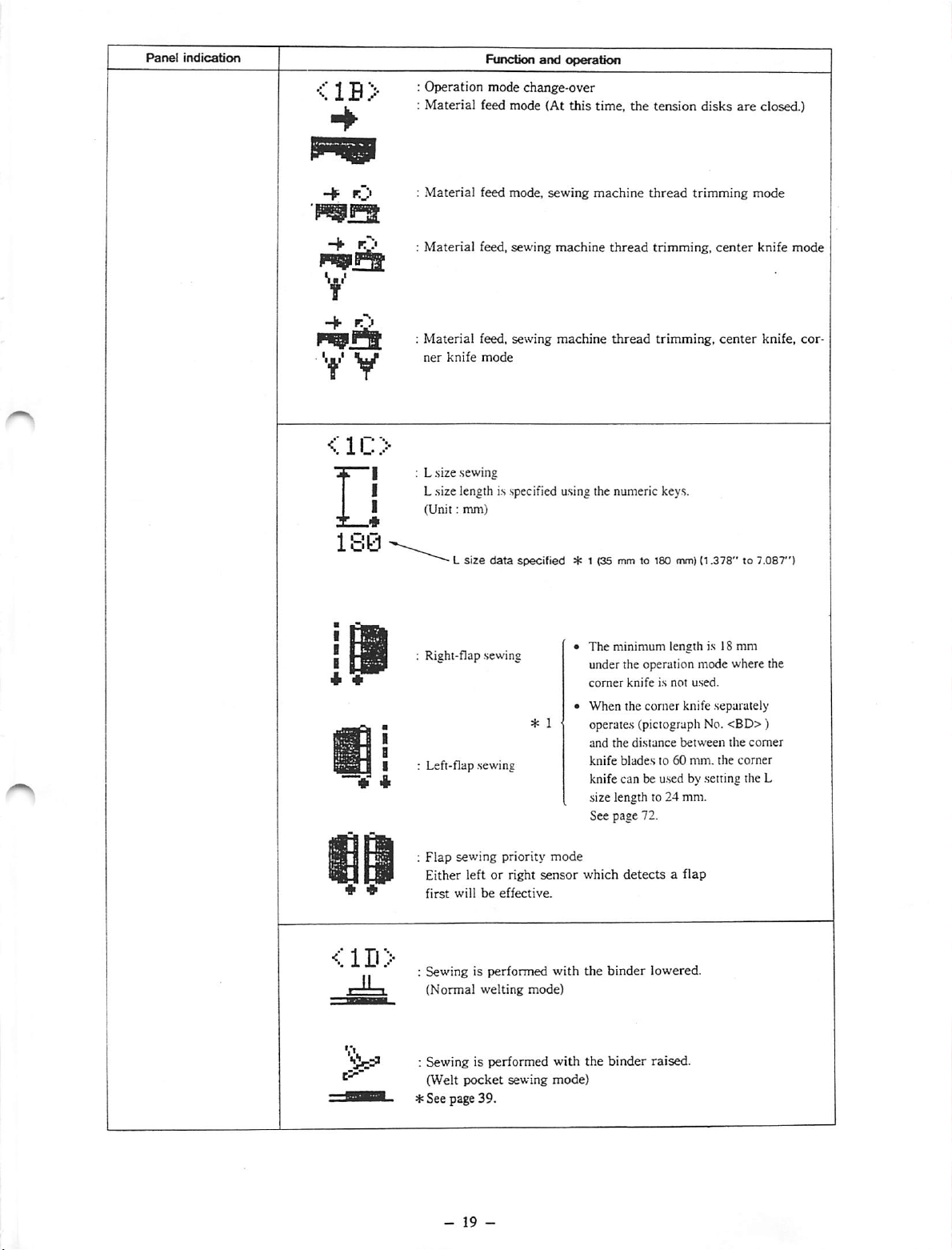
<1B>
L :
y V
<1C>
X—*
180-
:
Operation
Material
;
Material
:
Material
Material
ner
L size sewing
L size length is specified using the numeric keys.
I
(Unit:
knife
L
mm)
size
feed mode,
feed,
feed, sewing
mode
mode
change-over
feed mode (At
sewing
sewing
data
specified
this
time,
the
machine
machine
machine
thread
thread
* 1 (35 mm to 100 mm)
tension
thread
trimming,
trimming,
disks
are
closed.)
trimming
(1.378"to7.087")
center
center
mode
knife
knife,
mode
cor
<1D>
Right-flap .sewing
Left-flap .sewing
Flap
sewing priority
Either left or right
first
willbeeffective.
: Sewing is performed
(Normal
welting
: Sewing is performed
(Welt
pocket
sewing
*See
page 39.
mode
sensor
mode)
The minimum length is 18 mm
under the operation mode where the
comer
knifeisnot
When the corner knife separately
used.
operates (piciograph No.
and
the
distance
knife
bladesto60
knife can be u.sed by .setting the L
size length to 24 mm.
See page 72.
which
detectsaflap
with
the
binder
with
the
binder
mode)
between
mm.
lowered.
raised.
<BD>)
the
the
comer
corner
Page 24
Panel
incQcation
Function
and
operation
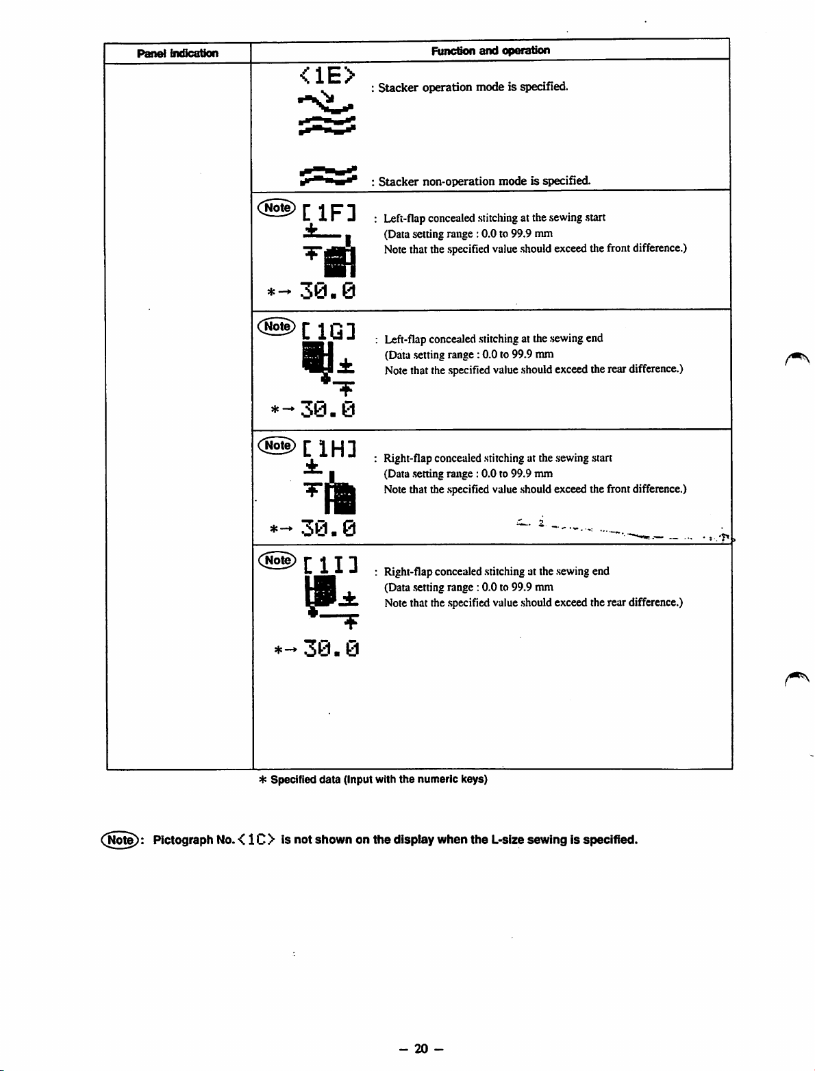
<1E>
30
• 0
±
*-30.0
(@)[iH]
n
*-*
30-
:
Stacker
:
Stacker
I
operation mode is specified.
non-operation
Left-flapconcealedstitchingat the
(Data setting range :0.0 to 99.9 mm
Notethat thespecified value
Left-flap
(Data
Note
Right-flap concealed stitching at the sewing .start
(Data .settingrange : 0.0 to 99.9 mm
Note that the .specifiedvalue should exceed the front difference.)
concealed
.setting
range: 0.0 to 99.9 mm
thatthe
.specified
mode
stitching
value
is specified.
.sewing
.start
.should
exceedthefrontdifference.)
atthe
sewing
end
should
exceed
therear
0
difference.)
(jiote):
Plctograph
No.
<1C> is
C@)
♦
-30.0
4: Specified
not
[11]
data
shown
Right-flap concealed stitching at the .sewingend
(Data .settingrange :0.0 to 99.9 mm
Note that the .specifiedvalue .shouldexceed the rear difference.)
(Input with
onthe
the
numeric
display
when
keys)
the
L-size
sewingisspecified.
-
20
-
Page 25
Panel
indication
C
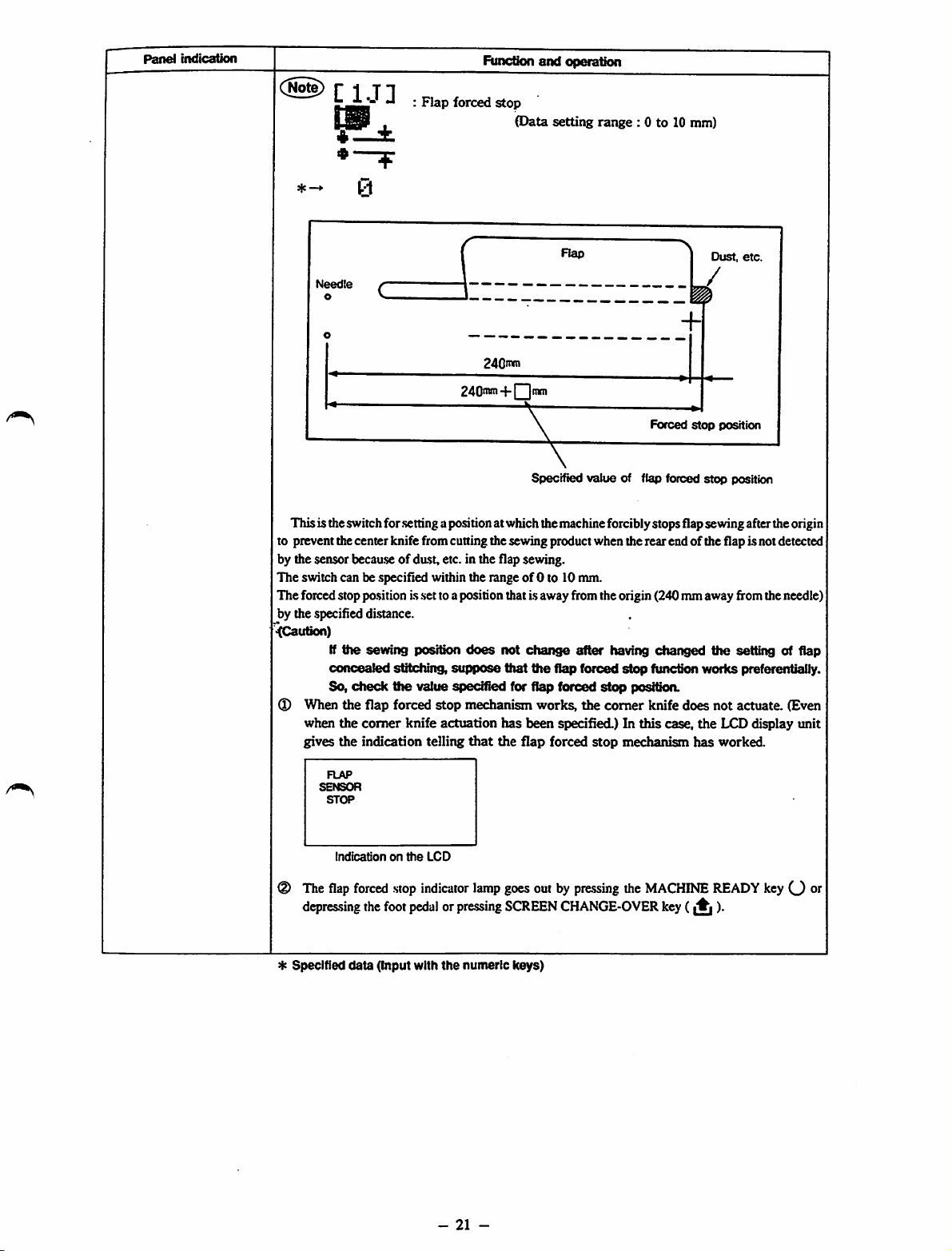
IJ]
Flap
forced
Function
stop
and
operation
(Data setting range : 0 to 10 nun)
Rap
Needte
o
240"*"
240'w-i-|
Thisis theswitchfor
to prevent thecenter knife fromcuning thesewing product when therear end of the flap is notdetected
by the sensor
The
switch can be specified within the rangeof0 to 10 mm.
The forced stoppo.sition is .settoa position that isaway from the origin (240 mmaway fromtheneedle)
by the specified distance.
<(Caution)
I
When
when
gives
becau.se
If
the
concealed
So,
check
the
the
the
.setting
apositionat whichthemachineforciblystopsflapsevnngafterthe origin
of dast, etc. in the flap sewing.
sewing
flap
comer
indication telling
position
sfttctdng,
the
value specified for flap forced
forced
knife
does
stippose
stop
mechanism
actuation
that
not
has
the
ttiat
Itnm
Specified
change
the
works,
been
flap
value
after
flap
forced
stop
the
comer
specified.) In
forced
stop
of flap forced
having
stop
posftkm.
mechanism
>
Dust,
etc.
/
Forced
stop
position
stop
position
changed
function worlcs preferentially.
knife
this
case,
the
does
not
the
LCD display unit
has
worked.
setting of flap
actuate.
(Even
The
depres.sing
*
Specified
Indicationonthe
flap
forced
the
data
(Input with
LCD
stop
indicator
foot
pedalorpressing
the
-
lamp
numeric
21
-
goesout by
SCREEN
keys)
pressing
CHANGE-OVER
the
MACHINE
key
(A
READY
)•
keyO
oi"
Page 26

Panel
indication
Function
and
operation
<1K>
I
IT
I 1
0
^1!
6
<1L>
i
±«
B
qp—*
0
I
l±
0
C
IM]
±i
I
^ll
7
Sewingstart
hand
(Data setting range: 0 to 20 mm)
(When this data is set to zero (0), the left-hand .seamand right-hand seam
are made in parallel with each other.)
Sewing startdifference (The left-hand
hand
(Data .setting
(When this data is .setto zero (0), the left-hand
are made in parallel with each other.)
Sewing end difference (The left-hand side seam is .shorterthan the right-
hand
(Data .settingrange: 0 to 20 nun)
(When this data is .setto zero (0), the left-hand seam and right-hand seam
are made in parallel with each other.)
Sewing end difference (The right-hand side .seamis shorter than the left-
hand
(Data .setting range : 0 to 20 mm)
(When this data is .setto zero (0), the left-hand seam and right-hand seam
are made in parallel with each other.)
Center knife actuating po.sitionon the .sewingstart
(Data .setting
[The center knife .starts operating at the position that is away from the
shorter .seamby the .specifieddistance.]
side
side
side
side
difiference
one.)
one.)
range:
one.)
one.)
range:
(Theright-handside seam is shorter than the left-
.side
seam is shorter than the right-
0 to 20 mm)
seam
and right-hand seam
0 to
1.5
mm)
Z
•±-ii
T**
^ Specified
IN]
<10)
t'i
^iV!
0.0
-lY!
0.0
data
Centerknife actuating
(Data .setting
I
[The center knife .starts operating at the position that is away from the
shorter.seam by the specified distance.]
Recommendable data .setting
Coriierknife
(Data .settingrange : 0.0 to 10.0 mm)
l'
[The
.setting
(Refer to page 30)
The comer knifeactuates at the
.specified distance.]
Comerknife
(Data .settingrange : 0.0 to 10.0 mm)
[The
setting
(Refer to page 30)
Thecomer
specified distance.]
(Input wittt tlie numeric keys)
po.sition
range:
0 to 15 mm)
range:
actuating
valueiseffectiveonly
actuating
valueiseffectiveonly
knife
po.sition
position on the
actuates
at the
on the
7 to 15 mm
onthe
when
position
when
position
.sewing
end
.sewing
.start
thecomerknife
insidethe
sewing
start
thecomerknife
outside
the
actuates
.shorter
actuates
shorter
separately.
.seam
by the
separately.
seamby the
-
22
-
Page 27
Panel
indication
Function
and
operation
<1P>
ili
0.0
I I I
fi
±.4,
0.0
C
IQ]
±_i
"T"!
2.0
<1R>
1.0
2.0
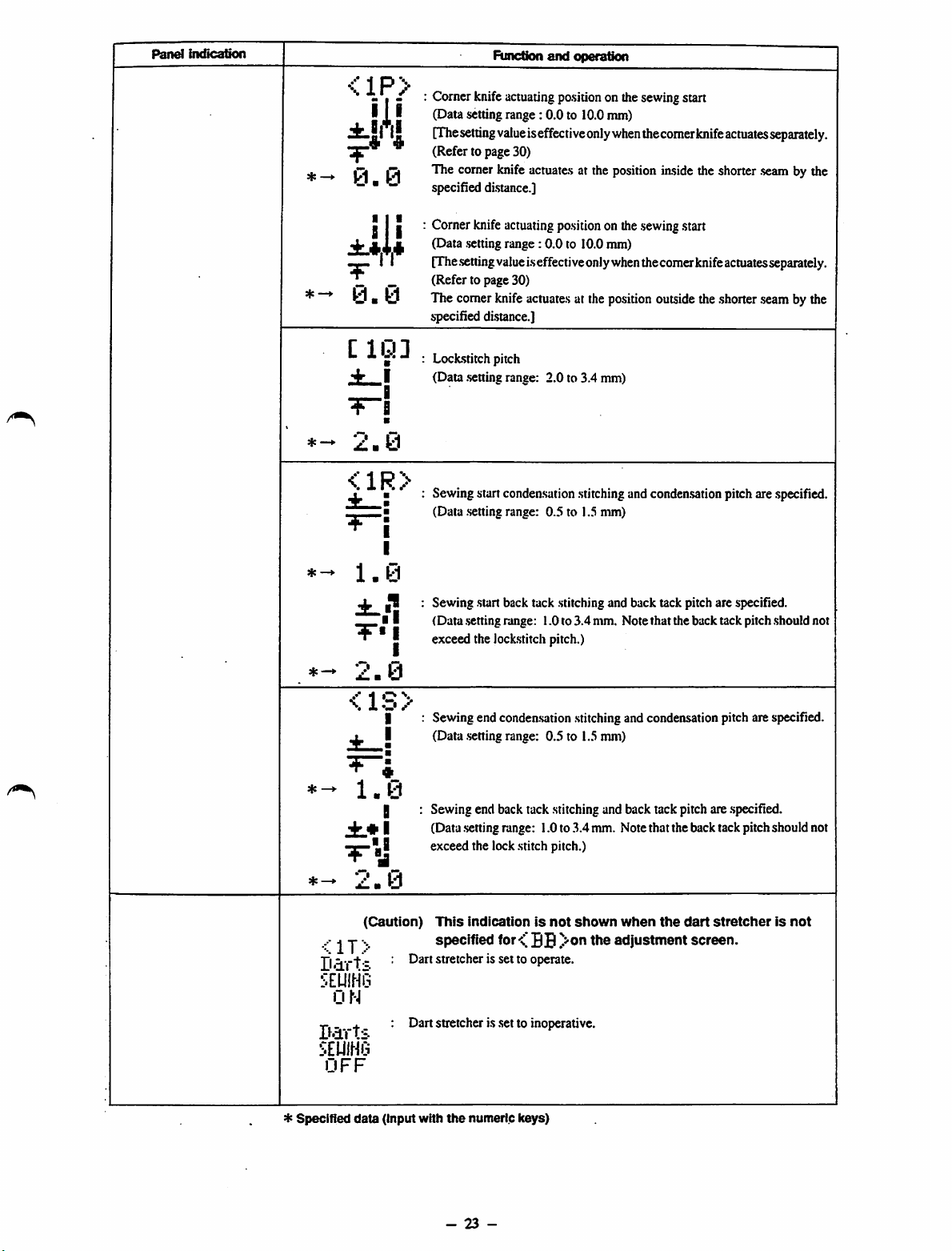
Comer knife actuatingpositionon thesewingstart
(Datasettingrange: 0.0 to 10.0nun)
[The
setting
value
iseffectiveonly
(Refer to page 30)
The comer knife
specified di.stance.]
Cornerknife
I
(Data .setting
[The
.setting
(Refer to page 30)
The comerknife
specified distance.]
Loclcstitchpitch
(Data
I
•
•
I
I
.setting
Sewingstart condeasation
(Data .settingrange: 0.5 to 1.5 mm)
Sewing start back tack .stitchingand back tack pitch are specified.
(Data .settingrange: 1.0to 3.4mm. Note that the back tack pitch should not
exceed the lockstitch pitch.)
actuate.s
actuating
range:
value
range: 2.0 to 3.4 mm)
po.sition
0.0 to 10.0 mm)
i.s
effectiveonlywhenthecomerknifeactuatesseparately.
actuate.s
when
thecomer
at the position iaside the shorter
onthe
.sewing
at the
position
.stitching
andcondensationpitch are specified.
start
outside
knife
actuates
theshorter
separately.
.seam
by the
.seam
bythe
*
Specified
Darts
smm
ON
Darts
smm
OFF
<1S>
1.0
jfc.* I
^•-1
2.0
(Caution)
j
data
I
H
(input
Sewing endcondeasation
(Data
.setting
range: 0.5 to 1.5mm)
Sewing end back tack stitching and back tack pitch are .specified.
(Data settingrange: 1.0to
exceed the lockstitch pitch.)
This
indicationisnot
specified
Dart stretcher is set to operate.
Dart stretcher is .setto inoperative.
with
the
for
numeric
keys)
BB
.stitching
.3.4
shown
and condensationpitch are specified.
mm. Notethat theback tackpitch should not
when
the
dart
stretcherisnot
adjustment
screen.
-
23
-
Page 28
Panel
indication
Function
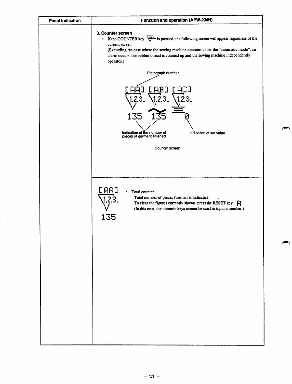
3.
Counter
• If the
screen
COUNTER
current
screen.
(Excludingthecasewherethesewing
alarm occurs, the bobbin thread is counted up and the sewing machine independently
operates.)
key is
and
operation (APW-234N)
pressed,
the
following
machine
operatesunderthe"automaticmode",an
screen
willappearregardless of the
C
flfl
\1.2.3.
V
[flfl]
\1.2.3.
V ^
135
Indicationofthe
piecesofgarment
3
Total
counter
Total number of pieces finished is indicated.
To
clear
(In this ca.se,the numeric keys cannot be used to input a number.)
Pictograph
CflB3
\1.2.3.
135
i-j
number
finished
Counter
the
figures
number
of
screen
currently
CflC3
\1.2.3.
0
\
shown,
indicationofset
press
the
value
RESET
key
^
135
-
24
-
Page 29
Panel
indication
Function
and
operation
[RB]
CflC]
\1.2.3.
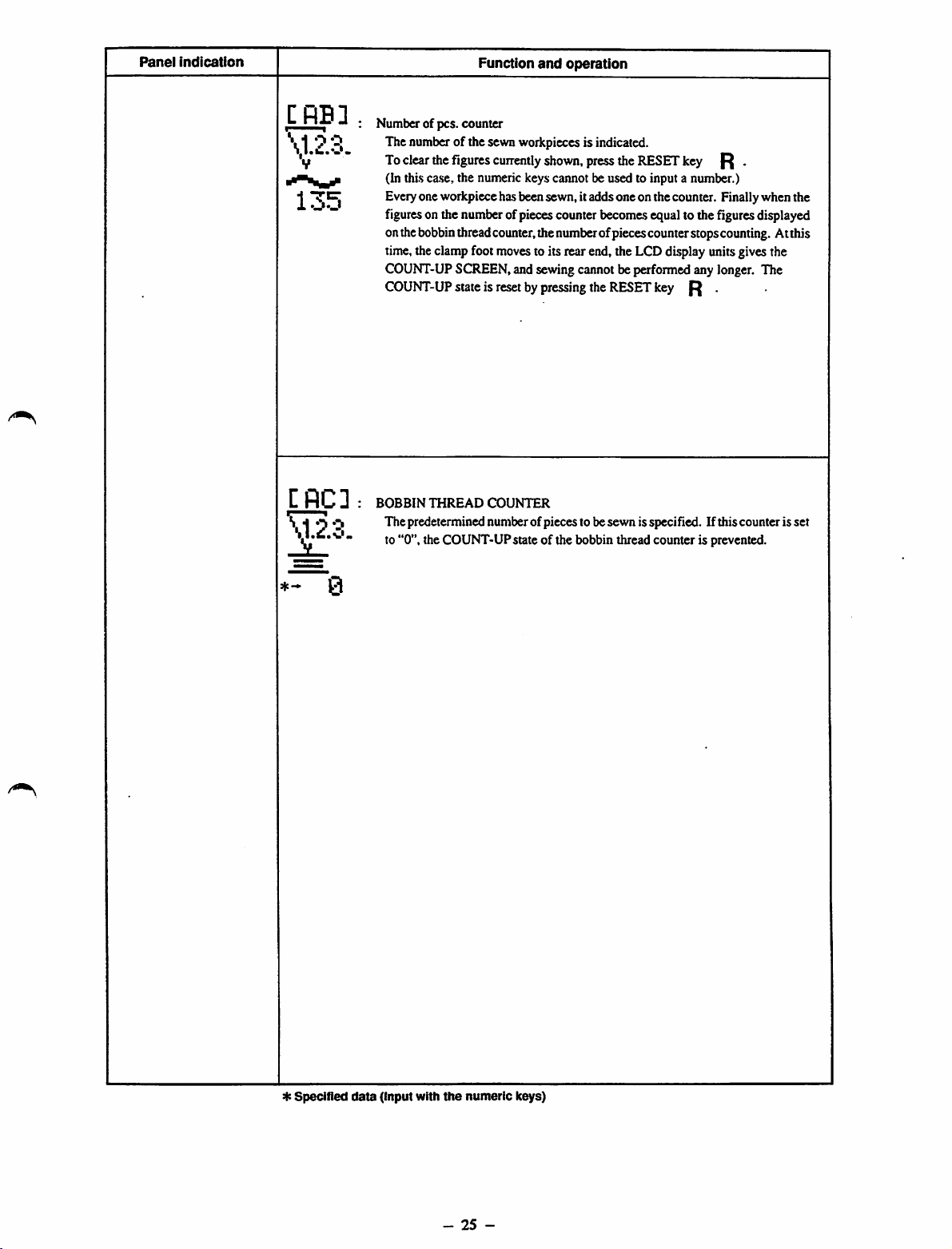
Number of pcs. counter
The numberof the sewnworkpieces is indicated.
To
clear
the
figures
cuirently
(In thi.sca.se,the numeric keys cannot be used to input a number.)
Everyone workpiece hasbeensewn, itadds one onthe counter. Finallywhen the
figureson the numberofpiecescounter becomesequal to thefiguresdisplayed
onthebobbinthreadcounter,the numberofpiecescounterstopscounting. Atthis
time,theclampfoot movesto its rear end, the LCDdisplay unitsgivesthe
COUNT-UP
COUNT-UP
BOBBIN
Thepredetermined numberofpieces to besewn isspecified. If thiscounter is set
to "0", the COUNT-UP state of the bobbin thread counter is prevented.
SCREEN,and sewingcannot be performedany longer. The
stateisresetbypressing
THREAD
COUNTER
shown,
press
the
the
RESET
RESET
key
key
R .
R .
*-
0
*
Specified
data
(Input with
the
-
numeric
25
-
keys)
Page 30
Panel
Indication
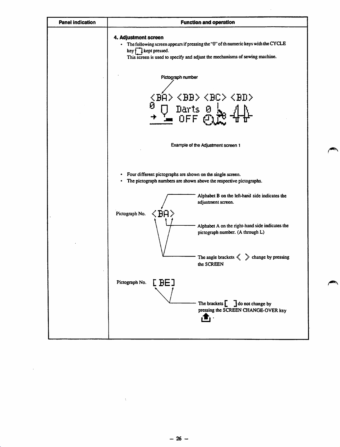
4.
Adjustment
• The
following
key kept pressed.
Thisscreenis usedto
screen
screen
Function
appearsifpressing
specify
andadjustthe
and
operation
the"0"ofth
mechanisms
numeric
ofsewing
keys
withthe
machine.
CYCLE
Pictograph
. / .
®
1?
• Four different pictographs are shown on the single screen.
• The pictograph numbers are shown above the respective pictographs.
y
/
w
Pictograph
No. /•'
\
\ /
number
....
<.BU>
D?rU
UFF
Example of the Adjustment
0k M
Alphabet
adjustment
Alphabet
pictograph
Bonthe
Aonthe
<%BD>
tTt
screen
1
left-hand
screen.
right-hand
number.(Athrough
sideindicates the
side
indicates
L)
the
Pictograph
No.tBED
\ 1
•••
Theangle
the
The
pressing the SCREEN CHANGE-OVER key
brackets
SCREEN
brackets
y*
^ ]donot
changebypressing
change
by
•ii
-
26
-
Page 31

rvj
(T-
..W
g ®|4 r:
<0
w
g
time
ON
operation
operation
)
speed
mode
clamp foot return
The
» a
9 B- 3!
:£
Setting ofdart stretcher operation
S<B<8
f 8.1
rik°
Timing of needle thread trimming
_
il
<a
Corner knifesimultaneous operation -> Separate operation
"
c»
m ^
ai
oi
m
1
timer
Stacker
c/
z •
i
Z S
> o
2
timer
Stacker
E
for high
speed
Setting the sewing
(n
T3
speed
for low
speed
Setting the sewing
Sewingmachineindependentoperation mode
operation
independent
machine
Sewingmachineindependentoperation OFFtime
Sewing
^ Check program
Page 32

Panel
indication
Function
<
Bfl
0.
>
00
The positionof theclampfoot is changedoverafter thecompletionof
sewing. = Stops at the front end
(Data setting range: 0.00 to 9.99 sec.)
* Length of time during which the clampfootstops at thesewing end
position is
The position of theclampfoot is changedoverafter thecompletionof
sewing. = Returns to the middle position
set
and
operation
^ n
-*•
T
n
T
<BB>
narts.
OPTIOH
OFF
Darts
OF'TIOH
0 N
<
BC
>
The position of the clamp foot is changed over after the completion of
sewing. = Returns to the home position
: The position of the clamp foot is changed over after the completion of
sewing. = Stops at the rear end
Darts stretcher is not equipped.
Darts stretcher is equipped. (Optionally available)
Timer
of the thread trinuner (standard timing)
©A
Timer of the thread trimmer (intermediate timing: (Length of thread
remaining in the needle) Standard position + Approx. 10mm)
Timerof the thread nrimmer(latest timing: Thread trimmer actuates
when the clamp foot stops at the position of the comer knife.)
S
hp
* Specified
data
(Input with
the
-
numeric
28
-
keys)
Page 33

Panel
indication
<BD>
*-80
[BE]
*-0.80
CBF]
I®
*-^0.80
Function
: Corner knife simultaneous operation designated mode (standard)
(Caution)Inthis
with
(Refer to
: Comer knife separate operation designated mode under which thedistance
between the corner knife blades
f Data setting range for gauge size 8 to 12
1
Data
setting
^The
comer
knife
automatically opens, by separately operating the fixed side and moving
^side of the corner knife.
(Caution)Inthis
should
marked
(Refertopage72for
Stacker
timer
(Data setting range: 0.00 to 9.99 sec.)
For a grasping stacker: The period of time during which the stacker
grasps the workpiece is specified.
For a bar stacker: The period of time during which the stacker grasps
the workpiece is specified.
Fora roller stacker: The period of time during which theroller actuates
is specified.
(Specify 9.99 sec. when the cloth sensor is used.)
Stacker
timer
(Data setting range: 0.00 to 9.99 sec.)
For a grasping
.swingsis .specified.
Forabar
The period of timeduring which the stacker swings is specified.
Foraroller
stacker:
and
case,
the
sewing
page
range
for
canbeoperated
case,
lie fixed in
withanasterisk
(unit:
.stacker:
stacker:
operation
fix
the
corner
knife
unitinaccordance
length.
72 for
the
procedure.)
Ls
specified
mm:
35 to 180 mm
gauge
size14to20mm:50to
inthe
way
similar
the
corner
knife
unit
accordance
{*).
the
procedure.)
second)
The period of time during which the stacker
Not
used
with
tothe
(the
the
180
mm
case
moving
specified
where
side)
data
it ^
CBQ]
High
* —
2200
CBH]
L O W
*—
1500
* Specified
r,j
data
(Input with
Setting the sewing speed for high speed operation of the sewing
machine (locksdtching speed)
Recommended set value 2.200 s.p.m.
(Datasetting range 1,000to
Setting the sewing speedfor low speedoperation ofthe sewingmachine
(condensation stitching speed and back tack stitching speed)
Recommended set value l,5()0$.p.m.
(Data setting range 500 to 1,500 s.p.m.)
the
numeric keys)
2,2(X)
s.p.m.)
-
29
-
Page 34

Panel
Indication
Function
and
operation
<BI>
M-0
r.J
M-l
r.y
r'1-2
r..*
M-3
r.j
Sewingmachineindependentoperationmodeis
Tostartthesewing
independent
No operation
Continuous
Continuous low-speedoperationof sewing machine
Intennittenthigh-speedoperation of sewing machine
Intermittent low-speed operation of sewing machine
machine
operation
high-speed operationof sewingmachine
independent operation,
modeandset theDIPswitchappropriately.
set
specify
firstthe
M-4
[
0-1
*-2.
C
0-2
*^2.00
CBL]
Check
PGM.
Mode
BJ]
r.J
00
BK]
r. >
0
Theperiodof timeduringwhich thesewingmachineisinits"ON"state
inthesewing
operation mode.
(Data setting range:
The sewing machine independent operation mode starts up using the
DIP
(Ifthespecifiedvalue is 1.00sec. or smaller,thesewing machinedoes
not operate.)
The period of time during which the sewing machine is in its
state in the sewing machine, independent operation mode or in the
intermittentoperation mode.
(Datasettingrange: 1.00to 9.99 sec.)
The sewingmachineindependentoperationmode starts up using the
DIP
Gfthe specified value is 1.00sec. or smaller, the sewingmachinedoes
not operate.)
Checkprogrammodeis specified.
(Available modes are
The check programis started up by pressing the SCREEN
CHANGE-OVERkey .
switch.
switch.
machine
independentoperationmodeorintheintermittent
l.CX)
to 9.99 sec.)
0.1,2,3
and 4.)
"OFF'
Specified
(Input with
the
numeric keys.)
-
30
-
data
Page 35

Pane{
indication
0 LCD indication
the
automatic
mode
under
1}
The
following
screen
is given
Rmction
under
and
the
operation
automatic
mode.
Indicationofcycle
sewing
Indication
of
£3"
Patterntobe
Patterntobe
Patterntobe
• If the screen shown above is givenon the
is
operative.
sewn
sewn
sewn
after
first
next
next
-
-1
-
-5
•
'6
158
l»
Detailed
-T-|
operation
1
stacker
operationJSewing
^11
11i
ON
150
Numberofpcs.
LCD,
only the
counter
MACHINE
ofthe
sewingisindicated.
mode
•+
O
\ti.3-
8
♦
indication
READY
indication
/
key ( (_))
-
31
-
Page 36

Panel
indication
2)
Exampleofthe
Example
L
size=120
indication showing
1) •
ParallelLsize
mm
Tb
L B B
ta
i B a
±4
*
120
Function
sewing
g
s
a
and
detailed
operation
operationofsewing
Example
Lsize=
2) •
Right-slantLsize
120
mm
p.
!• •
l"
•
i
120
Example 3) * Left trapezoidal
L
size=120
mm
Ti
i
ii*
120
Example
4) •
Right
parallel
B®
sewing
.stitching
flap
sewing
Example
Example
5) •
6) •
Right-slant,
Left
trapezoidal
ii
right-flap
flap
sewing
sewing
(Welt
pocket
sewing)
-
32
-
Page 37

Panel
Indication
Function
and
operation
<DAlarm indication
When an alarm occurs, themachine immediately stops. The alarm number coiresponding to die
alarm occurred flasheson and off on the LQ> display unit to show that the machine stops in the
alarm
state.
1) Temporary stop
Alarm
number
Pictograph corresponding to
Pres.sing
2) Thread breakage detection
the
Alarm
RESET
numtier
key
R
releases
the
the
machine
temporary
from
stop
the
alarm
state.
/
Pressing
3) The thread takc-uplever isnotin its highestdead position.
the
Alarm
RESET
number
key
R
releases
the
machine
*flL-04*
(Caution) The AL-12is
1. Turn
highest dead point when
At
2. Turn
highest
Thenpress the
reset
the
handwheeltomake
this
ime,
the
the
handwheeltomake
dead
pointwhen
following
machine is automatically
RESET
the
procedure
the
the
clamp foot is in
the
the
clampfoot
key p .
thread
thread
from
the
alarm
described
take-up
takenip
is in
levergouptoits
its
front
released
its
from
levergouptoits
intermediate position.
state.
below.
endorrear end.
the
alarm.
-
33
-
Page 38

Panel
indication
<D
Bobbinthread count-
up
indication
Function
1)
When
the
figures
onthe
numberofpieces
the bobbin thread counter, the following screen appears.
Press
the
RESET
key
R ,
and
cleared
(number=0) andthecyclescreenwillbeshownontheLCDdisplayunit
the
and
counter
figures
operation
shownonthe
becomes
equal
tothe
figures
numberofpieces
displayed
counter
will
on
be
The message of
"COUNT-UP"
flashes on and off.
COUNT-UP
\1.2.3. \1.2.3.
*.,/
1234
Total counter Number of pcs. Bobbin thread counter
V
135
counter
\1.2.3.
~35
-
34
-
Page 39

(3) Example of setting
Let's
set
dataonthe
^
Pattern
No.
1
L .sizel.iO mm. trapezoidal.sewing(difference 5 mm)
Pattern
No.
.*5
Left-flap parallel
Pattern
No.
6
Right-flap parallel .sewingwith the .stackeractuated.
Step 1. Specifydata on cycle
Under
the
manual
keys in the writtenorder succe-ssively. This completes the setting of data on cycle
Step 2. Specify data on
•
After
step1,press
pattern .screen will appear on the LCD.
• Then,
pre.ss
2-1 Changing the
•
Pre.ss
the
CHANGE-OVERkey , and the flashing pictograph will be changed to another (the
another).
• Operate the
the de.scribedon the next page.
2-2 Change the sewing pattern of pattern No. 5
• Keep pre.ssingthe CURSOR shift key until the pictograph number [ 1A] flashes on and off. Then, pressthe 5ofnumeric
keys.
• Operate the CURSOR .shiftkey , SCREEN CHANGE-OVER key and numeric keys to .setdata tothevalues same
as those of panem 5 to the described on the next page.
2-3 Changing the
• Keep
pre.s.sing
keys.
• Operate the CURSOR
as tho.seof pattern 6 to the de.scribedon the next page.
•
Set
valuesofpattern
dataoncycle
following
.sewing
the 1 of the numerickeys,and the
.sewing
CURSOR
SCREEN
.sewing
example.
.sewing
with the .stackeractuated.
.sewing.
mode
(when
panern.
the
SCREEN
pattern
corre.sponding
shiftkey • tochangethe
CHANGE-OVER key and thenumeric keysto
pattern of pattern No. 6
theCURSOR .shiftkey until thepictograph number [5A] flasheson andoff. Then,pressthe 6ofnumeric
.shift
key M . SCREENCHANGE-OVER key andnumerickeys to
1
sewing
the
mode
indicator
CHANGE-OVER
to pattern No. 1
LED
goes
out),
pre.s.s
the
CYCLE
key{3.
.sewing
(1,5
key
|j|j
(when
the
cycle
.screenisshownonthe
.sewing
patternof pattern No. 1will be shownonthe LCD.
flashing
pictograph
(itemthatcan be
.set
datato the valuessameasthoseof pattern1to
modified).
.specified
*hen
press
1,5
and 6).
LCD).
Then
Thenpressthe
data will be changed to
.set
datato thevaluessame
and6numeric
the
sewing
SCREEN
Clft]
<1B> <1C>
/\
-» ^ i i 1 4.»|«
1
Set
valuesofpattern
<5B>
Set
valuesofpattern
Cc-A]
<eB> <oC> <dD> <6E> C6F]
C
150
<5C>
<1D>
<5B>
<1E>
<1K>
<1L>
5 5 0 0
Trapezoidal
5
<5E>C5F]
\ /
Changethe data on flapconcealed stitchinginaccordance withthe flapto be sewn.
6
30.0
sewing
C5G]
30.0.30.0
Cc-GD
30.0
30.0
Cir-n
CIN]
<10>
<lP>Cli!]
^1
I
'I'
0.0
0.0
with
the
difference
C5H]
[513
30.0
C6H3
E6I3
30.0
30.0
Change the data on flapconcealed stitchingin accordance withthe flap to be sewn.
set
to S mm
C5J]
<5K>
1 0 0 7 7
Cc-JD
<6K>
1 0 0 7 7
<1R>
±_i
2.0
1.0 1.0
<5L>
C5M]
<6L>Cc.M]
I
<1S>
. I
C5N3
<50> <5P>
0.0
0.0
C6N3
<60> <6P>Cfc93 <bR>
0.0
0.0
C5Q3
2.0
2.0
<5R>
<5:f.>
1.0 1.0
1.0
1.0
-
35
-
Page 40

Step
3. Confirming
Pre.s.s
the
.sewing.
Press
the
MACHINE
data
on cycle sewing
CYCLE
READY
key
key
Q .
Q ,
1
^
and
confirm
.1 > 5
150
and
the
machine
150
ii
that
the
following
on
\
\/
ll
\/
IQ'
• 1'
indicationisgivenonthe
-''.X
>•
.6 >
LCD.
J
will
operate
under
the
-f
I V
automatic
mode.
Now,
the
sewing
machine
can
start
jrI t
71 I
6
ii
±*
150
♦
JL^
i-i
11
-
36
-
Page 41

(4)
(l)
Ex^ple
Rightslant
of setting data on slant flap sewing
sewing
and left slant
sewing
Right
Right
slant
Startofsewing
slant
sewing Left
flap
sewing
Left
slant
slant
sewing
flap
sewing
Observea
which
A
pocket
A
pocket
In addition,
flap
To sew a right slant flap, ase the right flap sewing mode.
[Theflapforced stopfunction (inprevention ofcutting) will not
work unlessthe
reference.]
endofthe
with
with
sewing.
pocket
its
its
the
.sewing
from
the
front after
pocketIsup.
right
end
up...
left
end
up....
above
designation
end of the flap is aligned with the rear
sewingtocheck
Right
slant
Left
slant
applies
sewing
sewing
alsotothe
Rear
reference
Iftheleft
.slant
[ Ifyousetthe
Setthe DIP
.switch
[ How to set a
flap
.sewing
modeisspecified for the
DlP-1
SW-1
toitsON
to the ON
Flap
li^t
slant flap ]
.sewing
ofa right
po.sition,
po.sition
whenonlyrightor leftflapsare sewncontinuously.]
the
occurrence
ofthe
aforementioned
.slant
flap,
"AL-50"will
"AL-50"
occur.
canbe
prevented.
-
37
-
Page 42

6.
HOWTOSET
DURINC
(1)
How
to perform welting and sewing welts withflaps
For
the
standard
Before
starting
operation,
1)
Depress
The
2)
Set
Place
Now
3)
SetabodyOfgarment material.
the
interlining
an Interlining piece.
iui
interlining
the
interlining
Placeagarment
cro.ss-marklight on the far side.
4)
Depress
The
work
clamp
Remove
wrinkle.s,
5) Depress the pedal switch to the
The
work
clamp
6)
Set
a welting patch.
Placeawelting
7) Depress the pedal switch to the third
Thebinderwill comedown to clampthe weltingpatch and thenfold it.
8)
Flap
setting
Set
the
flaptobe
9) Depress the pedal switch to the 4th
The
flap
pre.sser
10) Depressthe pedal switch to the 5th
The
flap
presser
11)
Depress
The
rapid
12) Releasethe pedalswitchafterthe rapidfeed begins a travel.
The
pedal
after it has reached the .sewingposition.
(Caution)
The
option.
THE
SEWINi;
operation,
set
check
foot valve switch.
clamping
piece
under
piece
materialina
the
pedal switch to
foot
travels
ifany,byhandfromthe
foot
(left)
patchinbetween
sewntothe
(right)
comes
(left)
comes
the
knee switch.
feed
beginsatravel
switch
mustbereleasedatthe
pedal
switch
MATERIALTOBE
the
workpieces
for
the
air
cylinder
the
i.s
firmly
correct
forward
will
come
predetermined
downtoclamp
downtoclamp
and
and
operate
related
setting
will
operatetopushupthe
interlining
heldbythe
position
the
and
the
clamp
usingthe
1st
step.
then
the
clamped
second
downtoclamp
left
and
right
step.
positiononthe
step.
step.
the
the
work
clamp
clamp
the
moment,
willbeoperated
SEWNONTHE
the
switchesinthe
keys,
switch-over
leaf
.springinalignment
leaf
spring
cros.s-mark
work
clamp
foot
garment
step.
clamp
right
left
foot
otherwise
ina
material.
the
garment
feet
left-orright-hand
flap.
(To
flap.
(To
will
travel
the
differentway
keys,
interlining
and
light,
(right)
material
utilizing
sew
sew
the
tothe
machine
MACHINE
following
and
indicators.
clamp
with
the
sewing
and
check
will
come
firmlyinplace.
the
cross-mark
sideofthe
the
left
flap,
right
flap,
sewing
will
directlygointo
whenadart
AND
order.
leaf
spring.
the
cross-marks
table
surface.
the
parallelismofthe
downtoclamp
light.
clamp
the
flap
presser
the
flap
presser
position.
the
stretching
OPERATE
and
release
garment
one
sideofthe
foot.
(right)
(left)
clamps
next
clamping
flap
presser is
THE
the
foot
material
garment
clamps
the
action
SWITCHES
valve
switch.
using
the
material.
the
pocket
bag.)
pocket
bag.)
immediately
installed
in
-
38
-
Page 43

(2) Howtosew
This
mcichine
(The sensor detects the well pocket to allow the machine to sew it.)
This
.sewing
a welt
pocket
is capable ofsewing a welt pocket whilesetting itdirectly on the garment body without lowering binder (welt patch ruler).
with
the
binder
raised
procedurecan becarried out underthe cycle sewingmode togetherwith regularflap sewing and weltingprocedures.
Flap
LJ-
Flap
presser
Welt
pocket
Garment
3) How to
Underthe welt pocketsewingmode, theflap sensordetects the welt pocketto allow the machinetoperform sewing. In thiscase,attention
.should
body
operate
be given to the following.
the
flap
Needle
sensor
sensor
of sewing
machine
Stay
The allowance ofthe welt pocket is halfof or smaller than the
gauge size. (Example : 6 mm or less when the needle gauge
is 12 mm) So, perform .sewingby the regular flap sewing
method
.so
as toeasure allowance when.sewinga
.suchaslinen.
When.sewinga weltpocket with inclined (with a difference),
2)
theinclinationcanbecorrected byinputtingconcealedstitching
data. If the welt pocket .shape(inclination) is not uniform,
however, the concealed stitches will vary. So, be careful.
(Same rule applies to the regular flap sewing.)
loo.se
fabric
Stopper pin
©©
Sensor
bracket
Welt pocket sewing Regular flap sewing
position position
Theiiradiatingpositionof the
different from that for the welt pocket sewing.
Holding the.sensorbracket(left) by hand, move the bracketto the
.sen.sor
fortheregularflapsewingis
weltpocketsewingposition locatedon theleft of theregularflap
sewing position.
(Caution) Be
suretomove
bracket
comesincontact
the
pin without fail. Be
allow
the
photoelectric
projecting
state
when
modeischanged
sewing
mode.
sensor
until
with
suretotake
celltoremain in
the
welt
overtothe
the
sensor
the
stopper
care
not
the
pocketsewing
regular flap
to
-
39
-
Page 44

4) Adjusting
1.
Increa.se
(Example)
30. 0 3Z 0
2.
Decrca.se
3.
Decrea.se
(Example)
30.
Increase
4.
the
flap
concealed
the
data
.setting
value
a
thedata
.setting
value
thedata
.setting
value
0 28.0 is
thedata
.setting
value
sewing
when
the
lengthofconcealed
Sewing length is shorter than that obtained when the
conceeiledsewing length at the start and end of sewing
is uniform by approximately 2 mm at
when
the
lengthofconcealed
when
the
lengthofconcealed
Sewing length is shorter than that obtained when the
concealed sewing length at
uniformbyapproximately2mm
when
the
lengthofconcealed
the
sewing
.sewing
sewing
start
atthe
.sewing
atthe
the
sewing start.
atthe
attheendof
and
end of sewing
sewing
attheendof
.startofsewingislonger
.startof.sewingisshorter
end.
sewingislonger
.sewingis.shorter
than
that
than
that
than
thatofatthe
than
thatofatthe
ofat
the
ofatthe
sewing
sewing
sewing
sewing
end.
end.
start
start.
5) Howtoset
Createawelt
the
MACHINE
(3)
Press
The
.sewing
left-hand clamp foot moves 10 mm outward.
pocket
the
MACHINE
pattern
the
materialonthe
.sewing
READY
key.
tobe
machine
patterninaccordance
(Refer
tothe
de.scriptionofpictograph
READY
.sewnis.shown
key.
onthe
withthe
display
operating
board
ofthe
procedure
No.<1D>
operation
ofthe
operation
for
howtochange
panel,
the
binderisfixed
panel.
Callthe
over
the
(DDepress the foot valve switch.
The aircylinderfor
(D
Set
the interlining in position.
Putthe
interlining
and release the foot valve switch. This .securesthe interlining in between the leaf spring and the .sewingtable.
(4)
Set
the
garment
Setthe
interlining
parallelism
(DDepress the pedal switch to the first
The
clamp
foot
creases on
® Depress
Theclampfoot (left)comesdown. This completesthegarment bodyclampingprocedure.
(7)
Set
Using
patterns onthe weltpocketwith
a welt
the
dans,
the
.space
.securing
under
body
atthe
ofthe
material
moves
tease the garment body to remove
aninterlining actuateto lift up the leafspringfor securingan interlining.
theleaf
.spring
in position.
predetermined
withthe
forward,
cro.s.s-mark
the
clamp
pedal switch to the
pocketinposition.
provided
aftertheclampfoothas
tho.se
for
.securinganinterlining
position
while
taking
onthefarside.
while
the
cro.s.s-mark
taking
the
cross-mark
for
.setting
step.
foot
(right)
comes
downtoclamp
crea.se.s.
second
on the garmentbodyplaced underthe welt pocket.
step.
moved
outward,
settheweltpockettothe
the
single
for
the
sewing
garment
predetermined
setting
reference
body.
sewing
performance
atthe
highest
the
.sewing
asa
Ifthe
garment
position
pattern
ofthe
position
reference
guide.
body
while
and
press
binder.)
andthe
asa
guide,
Check
has
many
matching
the
-
40
-
Page 45

Welt pocket
Garmentbody
'
Garment
clamp
moves
(10
mm)
® Depress the pedal to the 3rd step.
The flap presser (left) presses the welt pocket on the garment body.
(§)
Depressthe pedal to the 4th step.
The folding plate (right) comes forward. (Only when the needle gauge is 8 or 10 nun.)
® Set the stay in position.
Set thestay on the right of the welt pocket.
@ Depress the pedal to the 5th step.
The flap pre.sser(right)
®
Press
the
knee
The rapid feed .startsand the entire unit of the clamp foot moves to the .sewingposition.
pres-ses
switch.
the stay.
® Afterthe rapid feed starts, release the pedal switch.
Besure to release the pedal .switch.If the pedal is held depre.ssed, the machine will start the subsequent clamping action immediately
after the machine returns to the home position.
-
41
-
Page 46

7. EXPLANATIONOFVARIABLE
(1) Explanationoffunction
O VR (Variable
Thisvariable resistor is
display
resistor.
ODIP1
.screen
Resistor)
used
subtly
changesinaccordance
to adjust
RESISTORS
©—
•cs
-a
©—
»c=
o-
e
clearness
with
the
AND
DIP
SWITCHES
o
o
ofthe
liquid
crystal
display
screen.
Theclearness of the liquid
viewing
angle
and
ambient
temperature.Soadjustitwith
-Wideningdata input range, stoppingoutput of alarms in pan
OFF : Standard/ON :
Widen.s,
and stops output of AL-50 through
AL-55.
this
crystal
variable
(Caution) The
pressed
remain
data
specified using
(change-over from
evenifthe
the
the
settingofthe
-For settingfor specialfunctions(Referto Page 44).
-Switching between with/without Thread breakage detector
-Sewing
DIP
switches
manual mode to
DIP
switches
OFF:
Without
(Caution) When
detector/ON:
the
sewing
operationofthe
toavalue
pictograph
will
not
work
lower
No.[BG],
evenIfthe
"ON:(Provided with detecting function)"
-Stacker independent operation
OFF:
Stops / ON : Stacker actuates
•
Reserved
-Reserved
machine independent operation
OFF:
Stops/
ON:
Sewing machine drives
are
are
read at
changed
the
time when
the
automatic mode). Consequently,
when
the
machineIs in
With
speed
sewing
than
1,400
thread
the
detector
for
machine
s.p.m.
breakage
DIP
switchIsset
MACHINE
the
automaticmode.
the
has
READY
high
speed
been
through
detector
the
data
set
the
to
key is
will
Howtouse
• DIP-1SW-5
the
DIP
(stacker
switches
independent
operation)
Settingthe DIPswitches to its ONposition underthe "manualmode"will actuatethestacker.
• DIP-1 SW-8
(sewing
machine
Independent
operation)
The machinecan be operated independentlyfor adjustment Independentoperation of the
clamp foot is in its rear end position under the "manual mode".
-
42
-
.sewing
machine is
po.ssible
when the
Page 47

ODIP2
Selection of the position of clampfoot whenthe graspingstacker
or
bar
stacker
actuates.
^ :
The
clamp
foot
goes
^
130mmaway
:
The
clamp foot
Setting of stackers
from
does
backward
the
not move at all.
needle
untilitis
bar.
approximately
•
(Caution)
The
data
turned
the
powertothe
specified
ON.
So,besuretochange
using
machineisturned
the
DIP
switches
the
settingofthe
OFF.
•Setting
: 8
mm
1
§
i
i
1
are
readatthe
gauge
size
:10
mm
above-stated
:!2mm
P
time
Already
Roller
Grasping stacker/Bar stacker
:14
mm
:16
i
1
i
i
when
the
powertothe
DIP
switches,ifnecessary,
mm
reserved
stacker
:18
i
i
mm
1
i
machine
:20
mm
i
1
i
i
is
while
-
43
-
Page 48

(2) Settingforspecial-purpose functions using
1) Seting
the
DIP-SW
Operationsofthe
sewing
machine
canbeselectedbysetting
DIP
the
switches
switch
2of
the
DIP
switches1(DIP1-SW2).
-m
>^11
1
-m
^11
*•"11 1
1 1
•^11
1
1
D I
P-1
«>m
o
-n
-n
2)
Pressing
At
this
time,
the
cycle key,
the
"operation
press
the
change-over
numeric
screen"
key [1].
appeartoallow
(Caution) Ifthe "operation change-overscreen"
OFF
position. Whenthe switch is set to the
state.
r
OFF; Standard operations are employed.
(The operation change-over .screen
indicated.)
the
operatortoselect
does
not appear, supposethat the
OFF
position,all the operations
the
operation
DIP
i.s
not
ofthe
unit.
switch has been
will
be set to the standard
set
tothe
-
44
-
Page 49

Panel
indication
The
operation
SW2).
•
Pressing
Function
oftheunitcanbeselected bysettingtheswitch2 of theDIPswitch1(DIPl-
the
cycle
key .
press
the
and
numeric
operation
key
[1].
Now,
the
following
screen
will
appear.
<c.fl> <CB>
FLAP
MODE
0
FLAP
MODE
1
FLAPMODE
BIND
MODE
0
Darts
MODE
1
<0C>
Darts
<;cii>
. CLMP
MODE MODE
0
EIND
MODE MODE
1
R'^^'L
CLMP
L+R
<CE>
Pi
• I
M-0
Pi
• I
M-1
<CF>
CORO
MODE
0
CORA
MODE
1
Returnstothe
•a
o
E
The
aiTOws(T•iD)
and below the arrows can be changed over u.sing the
screen change-over key
initial
state.
means
that
().)
the
pictograph
CQ
given
above
o
eb
D.
E
O
(The specified data are the standard
value.s.)
C9 o
j>
o S
OA
»>
W C
u. M
u- %
5 I
Z es
O
S
"5.
-
45
-
Page 50

Panel
Indication
Function
and
operation
•"C*flX*
' "
*
The
FLAP
MODE
0
t
I
PL.fi
'
F*•The
Tl
J[|
£
Cr
I Qp :
j.
j-r-.
j~
't.
V sewing mode.)
(When
When
When
the
pressers
flap
presser
flap
presser
the
flap
sewingaright
sewingaleft
standard
operationinthe
perfonn
the
(right)
(left)
presser
flap,
standard
actuates
actuates
fir.st.
(optional)isinstalled.)
flap,
the
flap
the
flap
L-size
first.
presser
presser
sewing
operation.
(right)
operates
(left)
operates
modeorthe
first,
first.
welt
(This
pocket
is
<CB>
Darts-
MODE
0
ii'i'rts
f'lI1IIE :
"l
(Caution:
^
: The machine performs .standard operations.
The
foot
pedal
actuates
the
following
1ststep Darts stretcher operates.
2nd step Clamp foot travels forward.
i
Clamp feet (right) (left) come down.
3rd step Binder comes down.
4th step Flap presser (right) comes down.
5th step Flap presser (left) comes down.
Knee switch... Rapid feed
operations.
ThestandairdoperationsarecaiTledoutwhensewingmachineoperates^
coincldentally
sewing
under
mode.")
the
"darts
stretching
mode"
and
"welt pocket
j
-46
-
Page 51

Panel
indication
<CC>
*P{
J J|i :
w
j.r—
I'lUi-'C.
BIND
MODE
1
Function
The
standard
: The binder will not go up even by releasing the foot pedal after the binder
has come down and folding plates have been closed.
To
make the binder go up. press either the "knee switch" or the "reset
switch".
operations
and
are
operation
caitied
out.
<CD>
CLMP
MODE
R+L
CLMP
MODE
L+R
Performs .standard operation
Theclamp foot (right)comesdownfirst,then theclamp foot (left)comes
down
next.
Changes the clamp foot lowering order
Theclampfoot (left)comesdown first,thentheclamp foot (right)comes
down
next.
-
47
-
Page 52

Panel
indication
Function
and
operation
:cE>
h
B B
Performs the standard operation
(The
sewing
is changed over.)
M-0
Dfl
I B
M-1
'•..LrF.•'*:Performs
•JURO
The
sewing
condensationstitching, the operation of the sewing machine does not
change.)
standard
(Folding plateandflap presserare held closed when the corner knife
actuates.)
MODE
0
machine
machine
stopsonce
performs
operation
when
thebacktack
backtackstitching
stitching
without
direction
stopping.
(For
CORO
MODE
1
Foldingplateandflap presserare openedbeforethe cornerknifeactuates.
-
48
-
Page 53

8.
CROSS
MARK
LAMPS
(1) Cross (+)mark lamps for setting sewing
There
are
two
cross
(+)
mark
the
other
workpiece.
1)
How
lamps.Alamp
lamponthe
far
sideisusedtodetermine
to adjust the irradiation position of the cross
Fig. 20
—
Needle
i
' i
mm
-f-©
1
i
j
i © Rear r^erence
111
(Sewing
»-| •
Fig. 21
CM
E
E
o
10
1
clo.scrtothe
end
point)
the
pointatwhichaseam
operatorisusedtodetermine
starts
(+)
marklamps
Adjust
thecross (+)
steps of procedure.
1. Set the machineto its predetermined position,and turnON the
powerswitch. (The cross (+) mark lamps light up.)
2. First
3.
4.
5. After the adjustment of the focus, be sure to confirm that the
adju.st
referringtoparallelism
Loo.sen
set.screwO.and slide the entire unit of the cross mark
lamps
inthe
the far side irradiates the middle point
Now
re-tighten
Loo.sen
.setscrew-s©and
side. This
for sewing. Now adjustthe position of lampso that it irradiates
point
Thedistance fromthe needletothe lampshouldl)e240mm.
La.stly,
and
intothesharpestfocus
tighten
proper distance (240 mm) is provided between the needle and
thelampandthatthe
are aligned with the middle line between the needles.
© as
loo.sen
adjust
clamp
cro.ss
the
the
point
(rear
reference
(front
reference)
mark
the
lateral
direction
illustratedinFig.
ofthe arrow
setscrew
marklampisased todeterminetherear reference
mark lamp clamp screws© and
height
ofthe
having
screw
© and
cro.ss
and
lamps
irradiation
position
checking
©•
o inthe
21.
lampstobring
thewidthof 10
setscrew
mark
of the
until
images
and
adjust
the
pointin the
cross
cross mark
cross
between
cro.ss
mark
the
©.
projected
seam
parallelism
(+)
lamp
mark
lamp
cross
mm.
ends)
and
of
following
mark
lamps
light
©.
lamp© on
two
needles.
onthe
near
setscrew
mark
bythe lamps
Now
©,
images
firmly
Needle
Fig. 22
2) Howto replace
the
Bulb in
bulb in
the
Fig. 23
the
cross
cross
mark
mark clamp
lamp
Disassemble the lamp unit as illustrated in Fig. 23.
Replace the bulb with a new one, and then reassemble the lamp
unit accordingly.
-
49
-
Page 54

9.
AIR
CONTROL
SWITCHES
(1) Foot valveswitch
The foot valve switch is usedto actuate the interlining clamping
leafspringasshownin Fig24.Depressthefootvalve
it will permit the interlining clamping air cylinder to operate
causing the leafsprings to rise.
Whileyou
piece
position
valve
When attachedthe pocket bag clamping device, it performs the
sameoperationas interliningby the foot valveswitch.
aredepressingthefootvalveswitch,iasertan
between
thesewingtableandtheleafspringandaccurately
themusingthecross-mark light, thenrelease the foot
switch.
Pocket bag clamping
leaf spring
Pocketbag
air cylinder
Foot
clampingy
valve
Interlining clampingleaf spring
Interlining clamping
air cylinder
switch
Fig. 24
Foot
switch
unit
(2) Points requiring special attention when operating the air cylinder independently (Manual
operationofthe
Turn
the
knob
solenoid
valve)
Turn the knob on the solenoidvalve of the
cylinderandcenter knife in the direction of the arrow as shown
in Fig. 25, and each air cylinder can be manually operated
independently.
Use each air cylinder independently to
comer
adju.st
knifeelevating
components and to checkthemfor correctoperations. For the
normalsewing operation,set the knob at 0.
(Caution)
Fig.
25 mayInterferewiththe corner knife,causing
Be
suretomanually
knifeorthe
clampfoot to
corner
in
the
the
knife tobedamaged.
knife by
front
center
its
endofits
rear
hand
operate
knife
end.
when
stroke,
after
Ifyou
the
clamp
the
switch,
interlining
the related
the
corner
moving
operate
foot
clamp
and
the
the
is
foot
This machine is not provided with the air pre.ssure detector
switch. Before operating the
pre.ssureongaugeOfor
77
Fig. 26
-
50
-
air
.sewing
filter
machine, check the air
regulator
O .
Page 55

10.
PEDAL
Micro
switches
SWITCH
LS-1to-5
AND
KNEE
SWITCH
Pedal
switch
OPERATION
ijtr
Sewing preparation from the clamp foot forwarding to the rapid feed of the meaterial is all performed by operating this pedal
switch.
[Standard specification.s]
1st step
2nd .step (LS-2) Clamp foot, left
3rd step (LS-?) Bindercomes down
4th step (LS-4) Flap pre.s.ser. right comes down.
5th step (LS-5) Flap pres.ser, left comes down.
Knee
\
(LS-i)
.switch
(LS-6) Rapid feed
Clamp foot forward
Clamp foot, right
Folding plate clo.ses
i
(After
the
front
and then stops there.)
comes
comes
i
(Clamp
foot
comes
end
sensoristurned
down
dow
down0.2sec. afterthe
ON,the
clamp
binder
foot
lowest
moves
forward
end
.sen.soristurned
asfaras 5 mm,
ON.)
[When the darts .stretcheris installed] (Optional)
l.st.step(LS-1) Darts.stretcher oijerated
Clampfoot goes forward (After the front end sensor is turned ON, theclampfoot movesforward
as far as 5 mm, and then .stops there.)
2nd step (LS-2) Clamp foot, right comes down
3rd .step(LS-3) Clamp foot, left comes down
Darts
stretcher
4th .step(LS-4) Binder comes down
•I
(Clamp
Folding plate clo.ses
5th step (LS-5) Flap pressers (right and left) comes down
Knee
switch
(LS-6) Rapid feed
returns
foot
comes
down0.2sec.afterthe
binder
lowest
end
.sen.soristurned
ON.)
-
51
-
Page 56

[Undertheweltpocket sewing mode]
1st
step
(LS-1)
2ndstep
3rd
4ih
.'5th
Knee
(Underthe weltpocket witha darts .stretcher installed]
2nd
(LS-2)
.step
(LS-3) Clampfoot(left)comesdown.
step
(LS-4)
step
(LS-.5)
.switch
(LS-6) Rapid feed
l.st
.step
(LS-1)
.step
(LS-2) Clampfoot
3rd
.step
(LS-3) Clampfoot (left)comes
4th
.step
(LS-4) Flap
5th
.step
(LS-5)
Knee
.switch
(LS-6) Rapid feed
Clamp
foot
4.
(After
and then stops there.)
Clampfoot(left)comesdown.
Folding
plate
Flap
pres.ser
Dam
.stretcher
Clamp
foot
forward as far as 5 mm, and then .stops there.)
Darts
stretcher
pre.s.ser
Folding plate closes (for gauge size of 12 mm or larger).
Flap
pres.ser
moves
forward.
the
front
end
sensoristurned
closes
(for
gauge
(right)comesdown.
operates.
moves
forward
(right)
comesdown.
returns.
(left)comesdown.
(right)
comes
(After
down.
down.
size
of12mmor
the
front
ON,
the
.smaller).
end
clamp
foot
moves
.sen.soristumed
forward
ON,
the
asfaras5
clamp
foot
mm,
moves
-
52
-
Page 57

11.
POINTS
#
Make
1) Checkthat the electric supplycord and otherelectricconnectorsare firmlyconnected.
Tumthepower
sure that the motor of the machine properly rotates.
2)
Check
cm-(0.5 MPa). When necessary,adjust the
3)
Check
Fillthe oil reservoir of themachinehead with lubricatingoil.
4) Checkthat theremainings of theneedlethreadand
5) Makesure that the
1. The binder is in its upper position.
2. The clamp foot is in its upper po.sition.
Howto remove the sewing table when winding the bobbin thread
Sewing table
TO
BE
surethe
following
switch
for
the
connectionofeach
for the lubrication.
machine
NOTED
points
ONand
BEFORE
before
starting
check
thatthe
air
.supply
is in thestandby position;
OPERATION
operation
indicator
hose
including
pre.s.sure
(5.0kgf/cm-)by the air regulatorknob.
bobbin
ofthe
machineorday-to-day
figuresorindicator
thosetothe
lamps
stacker
onthe
and
ensure
threadareenoughforthe
1. Move the clamp fool to the rear end.
2.
Insert
your
fingersinholes
and pash up the .sewingtable with your fingens.
3. Inthisstate, move theleftand right.sewingtable,takingpo.sitioning
boss
O nsthe
and you
(Note) Be
contact
4. After thecompletion of winding the bobbin thread, securelyHtthe
.sewing
following tothe procedure for removing thesewing table inversely.
The
sewing
(Note)
Follow
table
center,
can
observe the bobbin ca.se.
carefulInmoving
the
tableto
throat
tableisattractedbymagnets
the
when
work.
operation
that
panel
the
pre.s.sure
operation.
O inthe
respectively
the
needle.
plate
O and
same
proceduretoremove
changing
the
are
both
gauge
under
inthe
sewing
positioning
needle
lighting.
indicates
.side
ofthe
direction
tablesoas
O nt
four
gauge.
Also
make
5.0
kgf/
sewing
table
ofthe
arrow,
not
to
pins O by
points.
the
sewing
Fig. 28
-
53
-
Page 58

12.
TEMPORARY
The
machine
actuated one of the following causes.
(1)
will
Temporary
Ifan
abnormal
stopswitch mountedon the topof theoperationpanel,
o The machine stops with the needle stopped in its upper position,
o The feeding mechanism stopswiththeclamp foot lowered.
The
function
[How
to reset]
Correctthecauseto have made thesewingmachinetemporarily stop, then
The
clamp
foot
lamp will go off and manual modewill start to function.
STOP
immediately
stop
stopbymanual
noiseisheard
ofthe
machine
will
travel
totherearend,and
with
the
relevant
error
codeonthe
operation
duringanoperationorwhen
will
stopin the
above
then
conditions
the
the
clamp
machine
anderrorcode
foot
operation
needs
and
binder
panel
tobe
"AL-Ol"
pre.s$
theresetkey.
will
returntohome
display
stopped
willbe
when
inan
the
temporary
emergency,
displayed.
position.
stop
pressthe
Theset
mechanism
temporary
ready
indicator
is
(2) Automatical
The automatical temporarystopmechanismwillbe actuated by one ofthefollowing reasons;
See [(3) "List of alarm codes*!
temporary
stop
-
54
-
Page 59

)
)
U)
tn
(3) List of
Alarm
code
AL-01
AL-02
AL-04
AL-09
AL-10
AL-II
alarm
codes
Description
Temporarystopswitch is turned
ON.
An abnormal load is applied to the
servomotor, resulting in defective
feed. In this case, the AL-02 is
shownonthe
.screen.
Thread breakage is detected.
AL-04isshown
thread
breaks.
Failureindetectionofthe
when
knife being in the lower end
position.
Failureindetectionofthe
knife being in the upper end
position.
The
binderisnotinthe
position.
1. The air
pre.ssure
has dropped.
This prevents the binder from
going up.
2.
When
the
darts
stretcher
been .specifled,the binder being
in the upper end position is not
delected.
the
correct
needle
corner
center
has
Corrective
measure
Press the reset key.
Press the reset key.
1. Check the load applied to the clamp foot travel components.
If any load is applied to them, eliminate it.
2.
Check
whether
the
servomotor
driverisdefective.
Check whether the needle thread is broken. Then, press the
reset key.
Press the reset key.
1.
Check
whether
the
corner
knife
has
come
2. Confirm that the cylinder sensor has detected the comer
knife in the lower end position.
Press the reset key.
1. Check whether the center knife has gone up.
2. Confirm that the cylinder sensor has detected the center
knife in the lower end position.
Pre.ssthe reset key.
home
1. Check the air
raised.Ifthe
pre.s.sure
darts
stretcherisnot
and al.soconfirm that the binder has
installedonthe
confirm that the darts .stretching mode has not been
specified.
2. If the darts .stretcher is specified, check the upper detection
sensor
for
the
binder.
down.
machine,
Timeofdetection
Anytime
During sewing
1. When the clamp foot travels
2. When thefoot pedalswitch isdepressed tothe
1st step.
1. When the
clamp
foot travels
2. When the foot pedalswitch is depre.ssedto the
Ist step.
1. When the power to the machine is turned
ON
2. When the clamp foot travels
3. When the machine ready key is turned ON.
Remarks
Page 60

Alarm
AL-12
code
Description
The thread take-up lever is not in its
highest dead point.
Corrective
measure
Set the thread take up lever to the highestdead pointof its
stroke.
Timeofdetection
1.
When
the clamp foot travels
2. When the machine ready key is turned ON
Remarks
3. When the foot pedal is operated
AL-13
AL-14
AL-15
AL-16
Dustgatherson the frontendof the
flap.
Front end of the flap is not detected.
Corner
knife
cannot
move
from
the
current position.
The flap .sensorfails to receive light.
Removedust from the reflectionplate, and press the RESET
key.
Pre.ssthe RESET key, and place the flap properly on the
machine.
Pre.ss
the RESETkey.
(Decrea.se
theopeningamountof the
corner knife, and re-.specifydata on it.)
Removedust from the reflection plate,and press the RESET
When the clamp foot feeds the material.
When the clamp foot feeds the material.
When
the MACHINE READY key is
When a short flap is
fini.shed.
pre.s.sed.
When the clamp foot .startsfeeding action. Only under the flap .sewing
key.
AL-17
Failureindetectionofthe
roller
stacker being in the upper end
position
AL-18
Failureindetectionofthe
darts
stretcher being in the upper end
position
Wl
o\
AL-21
Size, outside (he range of data
Pre.ss the re.set key.
1.
Confirm
2. Check the roller
that
the
roller
has
rai.sed.
.stacker
upperdetection sensor.
Pre.ss the reset key.
1. Confirm that the darts stretching cylinder has
2. Check that the cylinder
.sensor
has detected the darts
.stretcherbeing in the upper end position.
Prass the re.setkey, and input the correct data.
rai.sed.
While the clamp foot travels Only when the roller stacker
When the machine ready key is turned ON.
When
the
machine
ready key is pres.sed
Only under the flap sewing
mode.
Only under the flap .sewing
mode.
Only under the flap sewing
mode.
mode.
is u.sedwith the .sewing
machine
To be detected only when the
darts
stretcherisused
with
the .sewing machine.
Gauge
size:
8mmto12mm
35mmto
180
mm
Gauge size:
14mmto20mm
Page 61

Alarm
AL-26
AL-28
AL-29
AL-30
AL-31
AL-32
AL-34
AL-35
AL-36
AL-37
AL-38
AL-39
AL-27
code
Description
Lockstitch pitch, outside the range
of
data
Condensation pilcli, outside the
range of data
Back tack pitch, outside the range of
data
Dara on the flap concealed stitching
(front right) is outside the data
setting range.
Dara on the flap concealed stitching
(rear right) is outside the data
.settingrange.
Center knife (front), outside the
range of data
Center
knife
(rear),
outside
the
range of data
Dara on the flap concealed stitching
(front left) is outside the data setting
range.
Dara on the flap concealed stitching
(rear left) is outside the data .setting
range.
Dara on the corner knife cutting
length (front) is outside the data
.setting range.
Dara on the corner knife cutting
length (rear) is outside the data
.settingrange.
Dataonthe
front
difference
is
outside the data .setting range.
Dataonthe
rear
difference
is
outside the data .settingrange.
3 )
Corrective
Pre.s.s
the reset key, and input the correct data.
measure
When the machine ready key is
Timeofdetection
pre.s.sed
Remarks
2.0to3.4
0.5to1.5
1.0mmto
The
.set
mm
mm
value
the
should
lockstitch
larger than the front
differenceofthe
knife.
The
.set
value
should
larger than the rear
differenceofthe
knife.
0to15
mm
0to15
mm
The
.set
value
.should
larger than the front
differenceofthe
knife.
The
.set
value
.should
larger than the rear
differenceofthe
knife.
0 to 10
mm
0 to 10
mm
0to20
mm
0to20
mm
be
corner
be
corner
be
corner
be
corner
Page 62

Alarm
AL-40
AL-41
code
Description
Data on the flap forced stop is
outside the data setting range.
Error in setting the stacker
Corrective
measure
Press the RESET key. and input the correct data.
Timeofdetection
When the MACHINE READY key is pressed
0to10
Remarks
mm
AL-43
AL-44
Error in .settingthe gauge size
RAM
error
check
Set the gauge properly again.
Turn OFF the power to the machine, then re-turn it ON again.
It is necessary to
CPU
circuit
board.
check
(This
the
type of error will not occur
in ordinary .sewing works.)
AL-45
Errorofthe
front
end
.sen.sor.stodetect
and
the
rear
the
endofthe
Pre.s.s
the RESET key. then pres.sthe MACHINE READY key
again.
When the clamp foot travels to its front/rear
end.
clamp foot travel
AL.49
AL-50
AL-51
V/l
00
AL-52
AL-53
AL-54
AL-55
Needle thread breakage upper
detection
failure
Error in
.setting
the flap .slant.sewing
mode
In the cycle
.sewing
mode, the
openingamountof thecorner knife
i.s
.settoan
In the cycle .sewingmode, the .slant
at the .sewing.start
direction.
In the cycle
difference
In the cycle
at the .sewingend
direction
In the cycle
difference
incorrect
i.s.setanincorrect
i.s.set an
.sewing
.sewing
.sewing
value.
i.s
.setto a wrong
mode, the front
mode, the .slant
i.s
.setto a wrong
mode, the rear
incorrect
value.
value.
Check the needle thread breakage detecting sensor, then press (lie
RESET key.
Pre.s.s
the RESET key, and input the correct data again.
Inthe
.sewing
mode,change thedata to performsewing without
using the corner knife.
When the MACHINE READY key is prc.ssed.
When the MACHINE READY key is
pre.s.sed.
This error occurs only under
the
corner
knife
simultaneous
mode.
operation
Page 63

Alarm
AL-61
code
Dataonthe
corner knife blades (from the fixed
side to the moving side) is outside
the data setting range.
Description
distance
between
the
Corrective
Set
the
distance
value
between
"gaugesize of 8 to 12mm= 35 mm to 180mmor
the
corner
measure
knife
bladestothe
le.ss,
standard
gauge.sizeof14 mm or larger = 50 mm to 180 mm or le.ss ,
Timeofdetection
When the MACHINE READY key is
pres.sed.
Remarks
This error occurs only under
the corner knife separate
operation mode.
and input the valuewiththe relevantkeys.
AL-70
AL-71
AL-72
AL-75
AL-76
Ut
vo
AL-77
AL-78
Sewing machine motor is defective.
Synchronizer TG is defective.
Needle up/downsignal of
.synchronizer
Reverse rotation of the sewing
machine
Sewing speed for high .speed
operation has not been properly
.specified.
Sewing speed for low speed
operation has not been properly
specified.
Length of time during which the
.sewingmachine independent
intermittent operation is ON state is
improperly specified.
Length of time during which the
.sewingmachine independent
intermittent operation is OFF state is
improperly specified.
Check the .sewingmachine motor.
Check the .synchronizer.
Check the synchronizer.
Reverse the motor power connector and reconnect it.
Press the reset key, and input the correct data.
When the power to the machine is turned ON or
when starting sewing
When starting .sewing.
When the machine ready key is pres.sedor when
the
.sewing
machine independentoperationis
actuated
When the machine ready key is
pre.s.sed.
Wiicn the .sewing machine independent
operation is actuated
When the .sewing machine independent
operation is actuated
When the sewing machine independent
operation is actuated
Turn OFF the power to the
machine.
1000 to 2200 s.p.m.
500 to 1500.s.p.m.
500
to 2200 s.p.m.
1.00to9.99
1.00to9.99
.sec.
.sec.
Page 64

(4) List Ofcheck
In
the
seriesofoperaUonofthe
of
lime,
oneofthe
following
codes
indications
APW-
193N,
the
machine
wails
willbegivenonthe
forachangeinthe
panel.
So,
check
relevant
the
related
sensor
state
sensor.
and
proceedstothe
next
stepofoperaUon.Ifanyofthe
^ ^ ^ ^ ^ . ..
sensors,
does
not
change
its
state
foracertain
penod
the
the
binder
darts
Timeofdetection
actuates.
stretcher
actuates.
Corrective
appliedtothe
driver].
sensor.
and
lower
stretcher
positioning
detected.
detected.
Description
po.sitioning
signalisnot
signalis not
signalis
Check
any
load
the
servomotor
Check
Check
Check
the
load
i.s
appliedtothem,
the
binder
the
upper
the
darts
Alarm
codes
CH-02
CH-11
CH.12
CH-18
o\
o
Servomotor
detected.
Binder
detected.
Naeedle-up/needle-down
not
Dartsstretcherpositioningsignal is
not
clamp
eliminate
detection
sensor.
measures
foot
it.
ofthe
travel
components.
Servomotor
synchronizer.
[Check
When the clamp foot travels.
If
Whenanalarmisreset.
When
When the sewing machine actuates.
When
Remarks
Page 65

13.
ADJUSTMENTS
(1)
Binder
When
right clamp feet.
Afterawelt
position.
1)
Positionofthe
mechanism
youdepressthepedalswitchtothe
has
been
made,
the
comer
binder
when
lowered
third
knife
step,theair
has
completed
cylinder
its
will
cutting
actuate
and
operation,
binder
the
air
cylinder
willbe
lowered
raises
between
the
binder
theleftand
toits
upper
1. Turn thepower switchoffand lowerthe binderpressingit to the
direction of the arrow manually.
In
case
of needle gauge 10 mm
Sewing table
Fig. 29
5
mm
Fig. 30
I—
10mm
Binder
—
-0
5
Welt
fulcrum
Lock
mm
patch
nut
shaft
Needle
base
plate
2. The correct lowest position of the binder is obtained when the
bindercomesdowntoreachthepositionjust in the middleof the
two
needles
and
that
both
needlesdonot
welt patch base plate as shown in Fig. 30.
3. When the binder willnot be lowered to itslowest positionshown
inHg.,loosen
bymoving the binderunit to thedirection of arrowalong with the
welt patch scale supporting pin.
Fit
positioning
leverNo.1 0 and
setscrew
bolt 0
tighten
O and
securely
withthe
comeincontact
adjust
the
position
ofthe
ontothesidefaceofthe
lock
nut.
with
binder
binder
the
Binder
base
Welt
patch
base
plate
Fig. 31
-
61
-
Page 66

4. Provide about 11 mm clearance between the needle entry point
Needle
Welt
patc^
base
plate
11
mm
Fig. 32
Binder mounting
bases
O
and the rear end of welt patch base plate.
(Caution) Confirmthat the center knife
contact
5. When the dimension shown inRg. 32 is not obtained, loosen two
screws
which
showninRg. 33 andadjustthe
circuit
boardinthe
When the binder circuit board has been moved, tighten the
connecting
against
the
(Caution) Don't forgetto
stop
Alternatively,
thread
power
with
the
knife
are
used
tojoin
binder
dimension
directionofthe
screws
while
pressing
stopper
screwinbinder
set
the
position before you
you
can
take-up its highest pointsimpiyby turning
"OFF"
and
then
does
notcome into
coverofthe
mounting
binder
basesOand
movingthebinder
arrow.
binder
mounting
mounting
base
thread take-upto
start
sewing on trial.
set
the
machine
"ON".
O •
its
board.
base
upper
with
O
0
the
Stopper
screw
Binder mounting
bases
O'
Rg.33
Connecting
screw
-
62
-
Page 67

2) Concentricity between weltpatch base plate and centerof the needle
1.
Loosen
2. Slide base can be swung to each direction of the arrows by
tightening/loosening
3. Provideproper concentric angles betweenweltpatch base plate
and thecenter of the needle and then tighten locknut of adjasting
bolt O and
o.
(Caution) If
Binder
Fig. 34
boltO
which
securely
the
concentricityofthe
foot
with
regardtothe
clamp
footisnot
the
binder
with
the
procedure
the
screwinthe
the
machine
fix
bindermounting
adjusting
fix
binder
obtained,
regardtothe
described
installation
head)
for
base
O in
bolt
O .
mounting
directionoftravelofthe
the
baseO withbolt
binder
and
adjustthe
clamp
above.
(Do
support
clamp
foot
foot
the
position
following
not
(fixed
rail.)
position.
clamp
of
loosen
on
Centerofthe
Centerofthe
patch
base
Fig. 35
welt
plate
needle
)
Concentricity
-
63
-
Page 68

Horizontalofthe
3)
Check
and
positionof the binderand concentricangles.
g!
adjust
binder
the
horizontal
ofthe
•Binder
.Binder
•
Welt
Sewing table
Fig. 36
Locknut Aircylinder
binder
futerum
installation
patch
ruler
(the
shaft
base
welt
patch
base
plateisattachedinparallel
1. Lowerthe bindermanuallyinthesamewayasit isloweredwhen
its lower position is adjusted.
2.
Provide
abouta1.0
welt
paK:h
base plateand upper surfaceof the sewingtable and
make the clearance constant all the way between them (Be sure
that
the
differencebetween the frontand
base plate does not exceed 0.2 mm).
3.
Adjust
the
horizontalnessofthe
whichfixes thebinderinstalling base. Thensewing thewholeunit
of the binder in the direction of the arrow centering the binder
fulcrum
shaft
until
Afterthe adjustmentof thehorizontalnessofthebinder,securely
tighten
screw
O •
Adjustso thataclearanceof 1mmis providedbetweenthebonom
faceof the welt patchbaseplate andthesurface of thesewingtable
by
turning
cylinder
Loosen
the
locknut,
which tightens it to lower the welt patch base plate, or in the
direction which loo.sens it to raise the welt patch base plate.
Adjust the clearance to 1 mm, then firmly tighten the locknut.
tothe
table
nun
clearance
between
binder
the
horizontalnessofthe
rod © as
andturn
showninFig.
cylinder
surface),aswell
the
rear
endofthe welt patch
first.
binderisobtained.
37.
rod © in the
reverse
Loosen
asthe
lower
sideofthe
screw
direction
O
Fig. 37
-
64
-
Page 69

4) How to use the binder stopper nut
The machine has been designed to stop the binder at its intermediate
position to help enhance productivity.
Tousethis
fixed at the deepest end of stopper as illustrated in Ftg. 38.
(Caution)
Fig. 38
5) Cloth guide finger
The cloth guide flnger stabilizes the welt patches while they are being sewn.
(Caution) Be
suretocarry
out
this
adjustment
when
you
function,
have
The
lifting
reduced
light
emitted
changed
operate
the
amountofthe
while
from
the
sewing
machine
confirming
the
cross
needle
gauge.
with
stopper
binder
that
thereisenough
marking
should
lamp.
nut O
be
0.5to1.0
Cloth
guide
Cloth guide arm
Cloth
guide
Approx. 0.5 to
mm
spring
finger
L
1.0
r
Needle
mm
Cloth
guide
finger
Welt patch
Cloth
guide
base
arm
plate
1.
Loosen
cloth
guide
arm
setscrew
finger clo.seto the needleso that approx. 0.5 to 1.0 mm clearance
is provided between the side faces of the needle and the cloth
guide finger.
2. Adjust the cloth guide spring so that it lightly presses the cloth
guide arm. Be careful not to given an excessive pressure on the
workpiece while being fed.
Thepressingpressure ofthe clothguidespring can beadjustedby
screw O •
3. Provideapprox. 0.5 to 1.0mm (thicknessof a weltpatch)between
thecloth guide finger and welt patch base plate. When adjusted,
loosenlocknutOandprovideaproperclearancewithsctew
After
adjusted,
securely
tighten
O and
locknut
move
O .
the
cloth
guide
O-
Fig. 39
-
65
-
Page 70

(2) Adjusting clamp foot traveling mechanism
1) Tensionofthe clamp foot traveling belt
1.05±0.15kgf
Pulley on
drive
The
the
the
After
2) Tension of the clamp foot driving belt
the
side
tensionofthe
base.
(The
middle
ofthebelt
making
clamp
foot
traveling
pulley
canbe.shiftedbymoving
.slackens
the
adjastment,
tightenuplockout
belt
by8.6 mm
670
mm
Fig. 40
canbeadjastedbyloosening
adjustment
whenapressureof1.05±O.lSkgfisapplied.
screw©back
lockoutOand
and
forth.)
O •
Loosensetscrew O , and the tensionof the clampfoot driving belt
canbeadjustedby theidlerpulley. If thebelttensionis proper,when
0.4to0.5kgfpressure is
the belt will bend down approx. 1.5 mm.
After
adjusted,besuretotighten
shifting
The
tensiononthe
applied
Pulley on
the
slave
.side
pulley
belt
shouldbeadju,stedsothat
onthebeltatthe
middle
setscrewOsecurely.
slave
side
inside
the
ofthepulleys,
the
slot
in
Idler pulley
Fig. 41
-
66
-
Page 71

3)
Clamp
foot
front
end
stop
position
and
rear
end
stop
position
Standarddistances for proximityswitches location
For rear end stop position
Proximity switch
Detector plate
75
Rear
Garment
mm
end position
clamp
1 1
ICenterof the needle
C
180
mm
Fig. 42
1^1j j
[Front
end
240
255
position
mm
mm
For
5
mm
front
end
detector
Garmentclamp
15
mm
Clamp
foot
front
thestop
position
o
Clamp
foot
o
Clamp
foot
Detector
endstop
ofthe
front
endis
rearendis
pl^
position
andrear
clamp
footasshowninFig.42
where
tipof the
where
tipof the
i.o±
-Proximity switch
Fig. 43
end
stop
garment
garment
0.5
mm
position
are
tobe
determined
refeiring
clampis255mmaway
clampis180mmaway
tothe
standard
Providetheclearanceof 1.0± 0.5 mm betweentheproximityswitch
and the detector plate.
from
from
bythe
distance
the
the
center
position
for
center
ofthe
proximity
ofthe
needle,
ofthe
needle.
proximity
switches,
switche.s.
£>etermine
-
67
-
Page 72

(3) Clamp foot, welting patch folding plate and flap
1)
Parallelismofthe
The
left
and
rightclamp
oftheclampfoothasalreadybeen
If
readjustmentisnece.ssary
and
centerofthe
clamp
needle."
feet
feet
must
travelinparallel
adjusted
for
operation;
with
needles
infactorybeforeshipment.
adjust
referring
to"(I)
presser
and
the
Binder
mechanism
welt
patch
base
plate
whileswitches
mechanism2)Concentricity
are
between
made.
welt
The
parallelism
patch
ba.se
plate
2) Adjusting
the
lateral position of
tD=
¥
the
\7
garment
Stopper
clamp
1.3
0
mm
IW
1.3
mm
Adjustment
©
screw
Adjust
the
positionofthe
stepsofprocedure
.so
garment
that
a 1.3mm
(£) Adjusting the position of
The
positionofthe
O . and
Be
clamp
(Loosen .screw . and the
Adju.st
welt
move
.sure
totakecarenotto
(left)isconsiderably
the
.sewing
gamient
the
stopper
clearance
between
modeover to the
exce.ssively
clamp
dependingonthe
clearanceisprovided
die
garment clamp (left)
clamp
(left)isdetermined
tothe
rightorleft.
.shorten
changed
when
po.sition
of the cylinder can be changed.)
the
garment
clamp
.single
weltsewing mode.
(Let
airoutofthe
the
.stroke
replacing
andthe
Garment
sizesofthe
between
ofthecylinderwhen
the
clamp
Fig. 44
re.spective
each
bythe
.stopper.Toadjust
cylinderto.set
gaugeorother
welt
patch
garment
base
mlers.
clamp.
moving
occasions,
plate
inthe
Move
the
garment
the
position
itfree,
then
perform
the
stopper.
re-adJust
aforementioned
clamp
ofthe
garment
the
Notethatthe
the
fixing
way
taking
clamp,
adjustment.)
po.sition
po.sition
when
changing
the
below-stated
loosen
ofthe
garment
ofthe
cylinder.
the
.screw
double
-
68
-
Page 73

(D
Adjusting
Adjustthe garmentclamp(right)by
Loosen
(Turning
clamp inward.)
the position ofthe garment clamp
screwOand
the
adjustment
turn
screw
the
adjustment
clockwi.se
turning
theadjustment screw.
.screw
will
move
(right)
usingahexagon
the
garment
clamp
wrench
outward.
key.
Turningitcounterclockwise
will
move
the
garment
0 =0.2mm or
Fig. 45
less
The clearanceshown in Fig. 45 must be kept in parallel to the welt
patch baseplate. Make.surethat the difference between the front and
read ends of each garment clamp must not exceed 0.2 mm.
If
not,
loosen
.screws
O .
and
move
the
garment
directionofthearrowusingthe weltpatchbaseplateasreferenceuntil
thegarmentclamp (right)is in parallel tothe welt patch baseplate.
clamp
in the
Fig. 46
When replacing the gauge. adju.st the inside distance between the
clamp foot arms (right) (left) as shown in the table below. Loosen
.screw
0 ,
and
adjast
.separating them uniformly.
Gauge .sizeG (mm)
8
10
12
14
16
18
20
(Caution) Tighten
against
loose
fittingofthe
Fig. 47
-
69
-
the
clearance
screws
the
between
the
Inside di.stance between the clamp
foot
armsA(mm)
83
85
87
89
91
93
95
O while
clamp
clamp
pressing
foot
armsoastoprevent
foot
clamp
arm.
foot
the
arms
collar
by
Page 74

3) Gannentclamp lift
Clamp foot cylinder
Gannent
clamp
M
Liftingblock
The
garment
clampalwaysgoesupat thetimeof
The
standard
lifting
amountofthe
of
the
sewing
table
and
top
O
locatedatthe
the
lifting
After
adjustment,besuretotighten
(Note)
4) Adjusting the welt patch folding plate and the flap presser
Flap
Foldingplate
block
When
1.5to2.0
presser
top
endofthe
toadjustthe
adjusting the
mm
1to1.5
garment
endofthe
garment
clamp
lifting
amount
locknutOand
lift,
Needleofsewing
mm
foot
ntake
Q O
emergency.
clampatthe
clamp.
cylinder
rod
ofthe
garment
surethatthe
machine
•
Flap
presser
Folding plate
timeofemergencyisobtainedbyprovidinga25mmdistance
Ifitis
necessarytoadjust
and
screwOin
clampas
screw©securely.
/
xsx
Sewing
table
Fig. 48
the
lifting
amountofthe
the
guide,
and
change
the
desired.
garment
clamp
does notcontactthe
Adju.st
.so
that a clearanceof approximately 1to U mmis provided
betweenthe folding plate and the needle of the sewing machine as
shown in Fig. 62 and .sothat theyarein parallel to each other whenthe
welt patch folding cylinder is in the forward travel end.
To adjust the paralleli.sm between the folding plate and the needle,
loo.sen
folding
plate
fixing
.screw
adjust the front/rear of the welt patch folding plate, loosen
locknut©located
rod appropriately.
After
the
adju.stment,
atthetopofthe
.securely
garment
screwing
O and
cylinder
tighten
locknut
clamp,
depthofthe
sewing
perform
rod
© .
and
25
between
loosen
locknutOin
machine.
the
adjastment.
turn
the
the
mm
surface
locknut
To
cylinder
Fig. 49
Loo.sen
two
.screws
the front and rear of the flap
Fig. 50
-
70
-
© and
properly
pre.s.ser.
adjustthe
pres.sure
at
Page 75

5} Adjusting
Flap
the
stopper
flap scale
Fig.51
and
Flap
Fl^
the
scale
Black
Flap
base
flap presser
-Flap
presser
cylinder
marker
lines
presser
Loo.sen
screw intheflapscaleandadjusttheflapscale
theflap
width.
Notethatthe
are used asreference to check theparalleli.sm of the flap
Adjast
the
flap
pres.ser,
using
black
.screws
marker
O ,so
lines
that
engraved
itis^aced
depending
ontheflap
.scale.
approximately
1.5to 2.0mmfromthe centerof theneedleof thesewingmachine.
on
base
6) Adjusting
the
Flap
flap
presser
Flap
Garment
Fig. 52
stopper
piece
Flap
Flap
Flap
scale
base
clamp
piece
Confirm
Loo.sen
that
theflap
screwoand
pres.ser
adju.st
securely
presses
theflap
flap
stopperOinstalledatthe
pieceinposition.
topofthe
flapbasesothattheendoftheflapisalignedwiththesewingendposition.
Fig. 53
-
71
-
Page 76

(4)
1)
Adjusting
Changing
the
the
pocket
Positioning
collar
corner
Fig. 54
knife
lip length
Knob
Moving
side
rftfi
T
Rxed
(D
When
the
corner
designated
Whenthe
on the fixed side and that on the moving side can be simultaneously
actuatedfor the sake of productivity. Inthis case, the positionof the
cornerknifeshouldbeadjustedwheneverchangingthesewinglength.
Theknife
thefigure
properlyusingthedivisionson the
side
pocket
counterclockwi.se.
lip
mounting
mode
length
knife
simultaneous
Is specified
isnot
frequently
ba.seismovedbyturning
So,
adju.st
changed,
thepositionofthecornerknife
.scale
plateas reference.
theknob
operation
thecomerknife
illustrated
in
(Caution)
(Example)
(Example)
1. Besureto
closely
pressthe
positioning
coliar
againstthe
corner
knife
mounting
baseand
fix
the
to the base. (The collar should be fixed in place with the two screws loosened.)
2. Adjustthe blade ofthe corner
knifebymoving
the comer
knife
Inthe
moving
side towardthe corner
knifeon the fixedside. (Afterthe adjustment, return the corner knifeon the drivingside to the
positioning collar, and fix
3. Inthesewingmodeunder
the
knife at that position.)
which
front/rear difference is specified, itis necessary to movethe corner
knifeonthe movingsideinthedirectionofarrow A inaccordancewiththetwodifferentcasesshown
below.
a)
For
the
slant
sewing
Loosen
amountoffront
Sewing length 100 mm | i
b)
For
the
the
trapezoidal
knob, and move the corner knifeon the movingsideinthe direction ofarrow A bythe
differenceorrear
l~~i
I I
4
T
-Li-4
2
4
mm
sewing
mm
difference
I
whichever
Inthis
larger.
case,
set the corner knife to the
scale
of "100 - 4 = 96 mm.'
Loosen the knob, and move the comer knifeon the movingside inthe direction ofarrow A bythe
total
amountofthe
2
mm
tri~r
4- I I
5
mm
front
!• I
Sewing length 100 mm
I I
L
and
rear
differences.
In this
"100
case,
"(2+
set
the
corner
5) = 93 mm."
knife to
the
scale
of
collar
(D When
Itis
divisioasonthe
by tightening the knob.
* Underthis
(Caution) Ifthe position where the corner
the
corner knife
necessarytofix
.scale
For
standard
mode,
Consequently,
itis
not
necessarytomove
however,
knifeunit
the
(optional)
sewing,
the
comer
plate
until
adjastment,
theknifeon the
itis
not
machine
uses
shouldbe
use
separate
knifeatthe
the
the
distance
operation designated mode is specified
po.sition
position
.showing
between
moving
necessarytoadjust
the
knifeinaccordance
onlyone
the
shim
kind
replaced
type
ofthe
comer
corresponding
the
the
side
actuates
the
positionofthe
comer
inthe
ca.se
knife
tothe
dataondi.stance
figure
.sameasthe
knifeonthe
independently
with
the
differenceasdescribedin"Caution)
knife,
which
ofslantsewingor
input
moving
side
fromtheknifeon the
comer
knifeinaccordance
means
thatthe
trapezoidal
dataisreached.
and
cuts the materialfluctuates due to the materialslippage during
knife.
-
72
-
input.
the
knifeonthe
corner
sewing.
with
knife
Move
the
Then
fix
the
fixed
fixed
side.
the
pocket
3"of 1
blade
shouldbeadjusted,
comer
comer
side
shouldbe.set
lip
length.
de.scribed
knife
along
knifeatthat
Furthermore,
above.
orthecomer
with
position
to80
Note
the
mm.
that,
Page 77

2)
Positional
Sewing
knife
Garment
relationship of the corner knife,+
start
position
corner
clamp
Sewing
marking
end
corner
-O
lamp,
Fig. 55
knife
Center
needles
needle
andgarmentclamp
position
of
-240
Garment
255
mm-
mm
clamp
15
mm
G Gauge width
A
Dimeasions of assembly
D
Min. sewing length when L-size
has been input
3)
Adjusting
Corner
knife
unit
the
height of
8
134.5
7 9
Under
the
comer
10
135
knife
operation .settingmode 35 to 180
comer
Under the
knife .separate
operation .settingmode 35 to 180
the
corner knife
12
133.5
11
simultaneous
14
131.5
13
Underthe comer knife .simultaneous operation
setting mode 50 to 180
Under the comer knife .separate operation setting
mode35to
When
thecomer
theremustbea
both
mov
knife
clearanceofapprox.
ingsidecornerknifeand
faceofthetableasillustrated inthe
O .
and
adju.st
the
unit of thecomer knifeup or down.
16
130
15
180
elevating
heightofthe
18
128
17
cylinder
reaches
its
3.'5mmbetween
fixed
sidecomerknifeandthetop
figure
ontheleft.
corner
knifebymoving
20
126.5
19
lowest
position,
thetopendsof
Loosen
.screw
the
entire
Fig. 56
-
73
-
Page 78

4)
Centeroftiie
comer
knife
Deflection
Deflection of 0 ± 0.5 mm per traveling distance of 200 mm
of0.15mm
for
traveling
Travesng")'®®"^
distanceof300
TxpSwoLlSS
Corner
knife
traveling
Fig. 57
path
mm
00mm
Clamp
)mm(7.874")
(11.811")
foot
traveling
Needle
path
Center
the
of
needle
The center of the comer knife should be aligned with the center of the needle when the corner knife moves.
Although
external impact,
the alignment is correctlyadjustedat the timeof delivery,in the eventthat thecornerknifebracketis moveddue toan
loo.sen
thebolt
fixing
thecomerknife
frame
inplace,and
.shake
thewholecomerknife
bracket
.so
thattheclearance
betweenthe movingcorner knife andthecenter ofthe needleis0 0.5mmor lesswhenthe moving knifeis movedby approximately
200
nun.
Beforeadjustingtheclearancebymovingthecomerknifebracket,besuretoloosen
sideofthe
.shaft.
.screw
inthefixedbracketsupportingtheopposite
5) Adjustingthe deflection and distortion of the corner knife
If
the
comer
knife is attached with deflected to right or left,
V
I
Not
good
or distorted, defective state of the
I
Good
r
0.3to0.5
mm
vrr
flltistrated in the figure on the left. The comer knife should
cut
the
centerofthe
seams
and
Once the comer knife has been correctly centeredin terms
the seams, finely adjust the comer knife when attaching a
corner
knife
blade.
cut
should
part
not
cut
may result as
the
stitches.
of
^Seam
Ki
6)
i/H
Adjusting
the
0.3to0.5
0.3to0.5
Fig. 58
knife
mm
mm
When replacing oradjasting thecomer knife, firstly move theclamp foot to its backward travel end using the CLAMP FOOT
TRAVEL key on theoperation panel, .secondlyremove the .sewingtableand operate the comer knifeelevating solenoid valve
by hand to allow the comer knife to go up. Then, take the below-stated .stepsof procedure.
Afterthe
adju-stment,
carry out thoroughgoingtests to confirmno faultycut product isfinished. Then,start thesewingwork.
-
74
-
Page 79

d)
Adjusting
the
comer
knife for parallel sewing
Approx
12
mm
Fig. 59
The following de.scription explaias the adjasting method for the
corner knifefor parallel
1)
Adju.st
the
the
figure.s
2) Fit the corner knife in the groove in the comer knife holder.
Po.sition
the
needlegauge
therebyturning
Thi.s
temporarilyfixesthecorner knife. Thenperforma trial
.stitching
re-adjast the installing
notchmatching the
usingthematerialto be
.sewing
which
i.s
the.standardtypeof.sewing.
opening
amountofthe
on the left to 12 mm and temporarily tighten .screw
corner
knifesothat
i.s
providedbetweentheblades. Thenfixtheknife
eccentric
po.sition
.seam
comer
knife
holders
the
di.stance
almost
pin O inthe
is obtained.
direction
.sewn
intheacmalsewing,and
of the comer knife so that the
O in
sameasthe
ofthe
arrow.
Grooveinthe
knife
holder
Fine
adjustmentofthe
A
Fig. 60
Tip of the
knife
blade
G...
corner
comer
Needle
knifein
gauge
termsofseams
1)
Loo.sen
this
by
moving
eccentric
page,
and
the
adju.st
corner
pin0.shown
the
cutting
knifeinthe
inthe
figure
given
atthetopof
length0.showninthe
directionofarrow
O .
figure
(Caution) Whenmovingthe comer knife,top end 0 of
the
knife
should
2)
Loosen
screws0.shown
and
adjust
the
angleofnotch0shown
changing the openingamountof the corner knife holders.
be
inthe
covered.
figure
atthetopof this
in the
figure
page,
by
Fig. 61
-
75
-
Page 80

(D Adjusting the corner knife for slant sewing
When
using
the
corner
knife
inthe
slant
sewing
withadifference,
onthe
temporarily
fixed
position
of thecomerknifefor
parallel
adjast
the
sewingas
comer
explained
knife
following
ontheprevioaspage.
the
instructions
described
below,
based
Parallel
e
Sewing start difference ... A
Sewing end difference ... B
.1
Fig. 62
sewing
state
Let
the
blade
protrude
standard
positionbynarrowing
the angle of corner knife
Slant
from
O-
sewing
the
state
As an example, the adjusting procedure of
adapting to the following sewing
To adjust thecorner knife to sewing
pattern
.start
comer
is described.
difference A,comer
knife blade O on the left-hand side should be kept at the
.standard position as illustrated in the .sketchon the left, and
cornerknifeblade o
length in accordance with the difference as illustrated in the
.sketch on the right.
(Follow the procedure .sameas that de.scribedon the previous
page.)
.should
bemoved to extendthe cutting
knife
Parallel
sewing
state
Fig. 6.^
Fig. 64
Slant
sewing
state
2)
The comer
.similar
knifeisadjustedtorear
manner.
Only
comer
difference
knife
bladeO.shouldbemoved
toextend thecutting lengthin accordancewiththe
difference.
After the completion of the adjustment, finely adjust knife
blades
o
o.
o and O in
accordance
withthe
in theproceduresame as thatdescribedon the previouspage.
The corner knife can be adjusted by extending the cutting
length of the longer
.sewing.
.seam
regardle.s.s
of the kinds of
B in the
.sewing
end
.seam
.slant
-
76
-
Page 81

7)Replacing the comer knife unit (optional)
After
adjusting
previouspage,the entire unit of the comer knife can be replaced.
(T)
Removing
the
comer
thecorner
knifeinaccordance
knife
unit
Comer
knife
unit
with
the
respective
1)
differences
First,
cornerknifeunitwitha
the
Part
Fixed
Moving .side.. 18303552
(Note that the knife is excluded.)
fully
unit.
No.ofthe
side...
following
loo.sen
screw
corner
18303453
the
instructions
© in
hexagon
knife
unit
describedonthe
mounting
wrench
key
ba.se
supplied
O ofthe
with
Fig. 65
Pis.
Hexagon
wrench
2) Then, securely holding the mounting base, raise the
unit
straight
(Caution)
66
until it
comes
off.
Be sure to keep your hands away from the
comer
knife
blades
when
knife
removing
unit
the
comer
Fig. 67
-
77
-
Page 82

(D
Installing
the corner
Detent
0
Fig. 68
knife
unit
As
sameasin
holding the mounting base, insert the unit
into
the
(Caution) At this time,
the
caseofremoving
predetermined
unitsothat
figureonthe
position.
take
the
shaft
left).
careofthe
fitsinthe
the
imit, securely
straight
direction of
detent
Afterfitting theunitinplace,securelytightenthescrewwith
a hexagon wrench key.
down
(in
the
the
Fig. 69
-
78
-
Page 83

14.
MAINTENANCE
AND
INSPECTION
Inspect your machine periodically and maintain it in the
conditions
at
all
times.
following
ways in order to maintain the machine in good
If not, mechanical failures may result. So be sure to inspect and perform maintenance work periodically.
(1)
Pneumatic
systems
Press the drain button (white button) on the bottomofthe
(2)
Sewing
o
Clean
machine
up the
air filter, and water gathered in it
Drain
bunon
(white
button)
Fig. 70
head
sewing
componentsincluding the clampfoot eveiydaybeforethe operation.
wil}
come out.
Remove
from the oil reservoirat least once eveiy week,
o Beforeyou start welting,check if the center and corner
ifitis
still
serviceable,
knives
sharplycut the material.
Replace
the
o Inspect the oil level in the oil reservoir regularlyonce eveiy month.
dust and
duU
knifeeven
wastes
(3)
Maintenance
C Connectors uresubject to
for tight connection once month. Ifdast has gathered on thesurface of the control box,clean it up to remove dast.
Attach
not
and
touch
O
ODo
and
detach
the printed
the
connectionofthe
inspectionofthe
loo.sen
due to the mechanical vibration transmitted horn the machine head. Sobe sure tocheck the connectors
circuit
board
printed
electrical
after
circuit
systems
turning
board.
OFF
the
power
switch.
-
79
-
Page 84

(4) Precautions for the
90%ofthe
by
various
air"
then reduce productivity.
When
themasfollows;
troublesofthe
kindsofthe
might
cause
various
you
install
pneumatic
The standard airsourcedevicesprepared by the machineusers
compressed
pneumatic
air supplying (theairsupplysource)
equipments
impuritiesaswater,
troubles
and
resultina
equipmentstoyour
Main
are
causedby"the
dust,
inferior
oil,orcarbon
disorderofyour
factory,besuretoapply
line
filter
devices
polluted
air".
particles.
machine.Itwill
standard
The
compressed
Therefore
reduce
the
air
source
The
shipped with the
machineasstandard
Filter
air
using
this
working
supplying
air
source
regulator
polluted
poUuted
ratio
devices
devices
and
for
Air
compressor
After
cooler
The quality of the air source
When the watery air is supplied
The
environmentofthe
When
you
install
constant
Be
When
(Most
Besureto
within
suretoinstall
the
compressed
ofthe
troubles
install
the mistseparator.
Air
tank
Automatic
the
a day, or the temperature often dropsto
the
airis
of theair
dram
machine
machine
air
drver.
polluted
inthe
by a
solenoid
Automatic
place
where
large
amountofcarbon
valve
are
dram
the temperature isnot
causedbycarbon.)
Air
freezing
particles
f—1-=
Mist
dryer
cold.
ordust.
separator
ri
.
W Airsolenoid valve
inmi
jn;
Air
cylinder
—
-(^Precaution:
•Be.suretoprovidea1cm
of
the
•
When
of the
.
not
• Install the automatic drain devices toaUthe lower parts or dead endofthe pipe
to prevent water gathering.
Main
air
flow.
the
main
compressed
come
out
piping
work
de.scending
pipeisdevided
air
from
with
the air to
J-—
into
the
the
main
branch
inclination
some
pipe
pipes.
for
every
branch
pipes,
sothatthe
-
80
1mof
water
-
the
equip
inthe
air
pipetothe
atee
for
main
direction
the
outlet
pipe
does
Page 85

15.
Maintain
SEWING
and
MACHINE
adjust
the
sewing
HEAD
machine
headinthe
following
order;
(1) Removing
Remove
Removetheoil pan
theoilpan
-.£=1
.
j i
the
before
following
Fig. 71
oil
Oil
yy
pan
replacing
theprocedure
pan
II
the
gaugesorcarrying
©
described
out
maintenance
below.
Loosen
the
machine
pan in the direction of the arrow.
work
onthe
screwOfixing
fiameand
remove
machine
the
metal
themetalfittings
bed.
fittingsofthe
oil
pan
together
(Caution) 1. Removethe oilpan takingcarenottoallow
the
oil in
the
oil
pan
to spHl.
2. install
the
endsofthe
illustrated
oil
pan
after raising it until
oil
pan
fits
in Fig.
72.
Inside
receptacle
withtheoil
the
frame
to
both
as
Fig. 72
-
81
-
Page 86

(2) Lubrication
1) Lubrication of the oilreservoirinsidethefaceplate
and
the
timing
belt
Lubrication
fct-
On
gauge
Fig. 73
2) Lubrication of the hooks
Red
mark
hole
•JUKI
Pourthelubricating oilinthe reservoir throughtheoil holeuptothe
redmarkof theoil
Defrix
Oil
No.2)
gauge.
Usetheindustrial machineoil (JUKINew
(Caution) When you operate the machinewhich is newly
set
up or
has
not
been
used
foralong
time, apply a few
hole.
1. Set the AUTO STEPS selector switch on the operation panel to
"cloth feeding" operation.
2. Depressthe clampfoot travel keyand travel the clamp foot to its
rear end position.
3. lasert
(Caution) Only
you
finger
into
openings
tableo.o
sewing tables ineachdirectionof the arrows and remove them.
and
the
lubricated.
lubricated.
pushupthe
oil reservoir
The
drops
0 in the
sewing
and
oil
pan
of oil
tables.
the
does
bottom
hooks
through
of the
Then
needtobe
not
needtobe
periodof
the
oil
sewing
open
each
Fig. 74
Fig. 75
a
Supply
the
lubricating
feeder as
* Confirm the amount of oil in the hook bychecking hook oil gauge
(Caution) If
shown
o.
stop
the
in Fig. 75.
the
oilistoo
operating
machine
oil
through
lubrication
low tobeseenonthe
the
sewing
withanappropriate
holesOwith
machine,
amountofoil.
oil
and
the
oil
gauge,
supply
-
82
-
Page 87

3) Adjusting the amount of oil in the hooks
Fig. 76
(3)
Needles
U.seDPX17
of
materialtobe
1)
Howtoattach
needle
.sewn.
the
for
the
needles
APW-193N
sewing
machine.
The hooks are automatically lubricated. Adjust the amount of oil
lubricatedbyscrewOlocated
screwtothe
increasetheamountof oil. Holdapieceofpaperabout 1cm awayfrom
clockwise
will
outsideofthe
reduce
andtothe
hooks.
counterclockwise
thehookandoperatethemachineforabout10seconds,andthesplash
of oil will gather on the paperas shownin Fig. 78 if the
amountofoilislubricatedtothe
Chooseasuitable
sizeofthe
needles
for
hooks.
the
thickne.s.softhe
threadsorthe
Turning
adequate
the
will
types
(4) Threading
1) Type of threads
Left
0
the
hand
Fig. 77
machine
twist
thread
head
and
winding a
lasert theleft andrightneedlesas faras theywillgo pointingtheirlong
grooves
ateachotherand
tighten
screw
O .
bobbin
Use a new threadofeven thickness. If not, it may fail to make fine
stitchesormay be brokenwhile beingstitched.
thread (Z twist) for the
needle
but
either
U.se
theright handtwist
twist will do for the bobbin.
Right tiand twist thread
Fig. 78
-
83
-
Page 88

2) Threading the machinehead
Thread the machine head in the order illustrated in Fig. 79.
The
left
needle
thread
viewed
from
the
The
right
needle
thread
viewed
from
operator's
the
side
operator's
side—>©
\
©
Fig. 81
E
o
-
84
-
Page 89

3) Winaing bobbin
You
can
wind
two
bobbinsata
1. Puttwo bobbinsinto the threadwindershaft as faras they willdo.
2. Threadthe
threadonto
3. Press
4. The threadwinderwill automaticallystop as
up the bobbins to a predetermined amount.
Fig. 80
4) Adjusting the thread winder
It is recommendable to wind the bobbin about 80% of itsfull capacity with the cotton thread or 60to 70% with the .synthetic thread.
Thiscanbe
adjastedbytightening
.screwO(Fig.
80)to
increa.seorloo.seningtoreduce
winder
winder
each
thread
intheorderas
bobbin
time.
fourorfive
guide O •
the
amountofthread
illu.strated
turns.
inFig.80andwindthe
.soon
as it haswound
tobe
wound.
5) Threading the bobbin ca.se
Bobbin
case
mi
""10
Fig. 81
6)
How
to install the
bobbin
lii
case
1. Hold inhand a bobbin in the way that it spins clockwise and put it
into
the
bobbin
case.
2.
Pass
the
thread
through
slot O inthe
3. Pull the thread to pass it under the tension .spring.
4.
Passitthrough
Rt
thebobbincasesintothe hookdrivingshaft, andtilt thehooklever.
hole O on the
bobbin
bobbin
case.
case.
Fig. 82
-
85
-
Page 90

Thread
(5)
Needle
1)
First,
1.
2.
2) Bobbin thread tension
thread
adjust
Then,
left
bobbin
it
(Fig. 81)
Set
the
Bobbin
tension
tension
the
tensionofright
adjust
therightneedle
thread
operation
Bobbin
case
tension
selector
and
left
bobbin
thread
tensionbynutOand
respectively.
keytothe
Turn
"feed"
threads.
the
respective
side,
and
(The
standard
nuts
the
thread
Turn to
thescrew counterclockwiseto decrease it. Standard bobbin thread
tension is 30 to 35 g.
tensionis30to35
the
left
needle
thread
clockwisetoincrease
tension
controller
screw
clockwise to increase the bobbin thread tension or turn
g.)
tensionbynutOaccordingtothe
the
tensionorcounterclockwisetodecrease
willbeclosed.
right
and
Fig. 83
Adjusting the thread take-upspring
3)
For
adjusting
increa.se
For
adjusting
increase
For
adjusting
Turn ©
Adjust
the
tensionofthe
the
tension
oftheleft
the
tensionofthe
the
tension
ofthe
the
strokeofthe
clockwisetoincrease
the
strokeofthe
right
right
left
needle
right
needle
left
the
needle
needle
thread
needle
thread
needle
stroke
thread
thread
take-up
thread
take-up
thread
ofthe
take-up
take-up
spring,
spring,orcounterclockwise
take-up
spring,orcounterclockwise
take-up
spring,
thread
take-up
springinthe
(6) Adjusting the position of the needle bar frame
I
loosen
screwOand
spring,
loosen
screwOand
loosen
screw
© ,
springor
Loosenscrew O , and adjustthelongitudinal positionof theneedle
bar
frame
thethroatplate.Then
counterclockwisetodecrease
same
procedureasmentioned
to allow
the
turn
will
decrease
turn
will
decrease
and
turn
needle to
.secure
theneedlebarframetighteningthescrew.
Turning©clockwise
O
it.
© .
Turning
it
© .
it
above.
(Fig.
enter
the
centerofthe
© clockwisewill
79)
needle hole in
will
89.
OSnsn
Fig. 84
-
86
-
Page 91

(y)
Relationofthe
1) Adjusting the hook to the needle
hooktothe
needle
Hook
blade
Needle
point
1. Remove the throat plate.
2. When the needle has goneup 3.1 mm fromits
the
po.sition
centerofthe
needleguardOprovidesaclearance
needle and that its blade point is located 0.8 mm above the level of
the top end of the needle eye.
0
to-0.05
2) How to adjust the timing of the hook
3) How to adjust theclearancebetweentheneedleand the hook bladepoint.
mm
Fig. $5
Fig. 86
-s-OtoO.05
mm
Loosen
three
turnthe hookto make the hookblade pointalignwith thecenter ofthe
needle.
Then
and the gear upwards in order to eliminate a vertical play of the hook
shaft.
lowe.st
point,adjast
of the hook so that its blade point is in line with the
needle
setscrew
tighten
.setscrewOwhile
withaclearanceof+
O inthesmallgearofthehookshaft.
0.05mmor le-ss,
of-0.05 mmor
pressing
the
hook
le.s.s
Manually
downwards
that
atthe
its
Centerofthe
Fig. 87
4) Removing and attachingthe hooks
O Removingthe hooks 1. Remove thethroatplate
O Attaching the hooks
needle
Remove the opener.
2.
Loosen
3.
4.
1.
2.
three
Turnthe
Installation is carried out analogously in reverse order.
To
on the throat plate and fix the throat plate.
attach
handwheel
the
ofthe
throat
screws
untilthe
plate,
1. Remove the oil pan.
2. Remove the throat plate.
3.
Loo.sen
screws O and O in the hook
the machine
4.
Lightly
orrightuntilthe
of the hook is adjusted to between 0 and 0.05 mm. Then firmly
tighten
tap
hook
screws
side
to be adju.sted.
driving
clearance
O and O .
shaft
between
saddle
(Caution) When the hook driving shaft
ordertoreplace
of oil
and
Loosen
spiash
0 (right)
screw
the
prevention
need
O in oil
O ,
the
needle
gauges
to be
driving
and
move
andthebladepoint
saddie
etc.,
plate
adjusted.
splash
plate O (left),andad|ustsothattheendfaceof
the
O inthe
needle
turn
the
Loosen
plate 0 (right),
the
plateinthat
pinion
ofthe
baris raisedto its
bobbin
case
holderbyhand
plateis alignedwith
screw
arrow
until it wlligono further.
position by tightening
hook
driving
highest
until
the
centerofthe
0 in oil
and
shaft
splash
move it in
(Fig.
88).
the
position andtakeoutthe
its
projection
rests
shaft
located
itto
is moved in
the
position
O (left)
prevention
needle.
prevention
direction of
Then
the
screw.
hooks.
inthe
on
the
left
fix
the
groove
-
87
-
Page 92

5) Adjustingthe bobbin case openinglever
0.2to0.3
Turnthe
opening
This
mm
Fig. 88
handwheel
lever©withdrasv
and make sure that there is a clearance of 0.2 to 0.3 mm between the
bobbin
case
the bobbin case inthe arrowdirection and hold itin place by your hand).
byhandintheregular
opening
lever
totheendofits
and
projection©ofthe
canbeadjustedbyloosening
(8) Adjusting the needle thread knife,center knifeand bobbin thread knife.
These
cutting
devices
are
operated
1) Attachingand removing the needlethread knife
3
mm
23.5
Fig. 89
mm
bytheair
Throat plate
cylinders.
When
youmake
1.
2.
3. Replace the needle thread knife with a new one.
2) Height of the needle thread knife
3) Sharpness of the needle thread knife
adjustment,
Remove
knife
Loosen
ridge, turn the pin to pull out.)
At
against the counter knife.
Provide
thread knife and the throatplate when the needle thread trimming
cylinder
heightof the needle thread knife by raisingor loweringit.
Loosen
needletothe
The sharpne.ss of the needle thread knife depends on how it
interlocks
0
and rightblades even interlock 1mm with the bladeof the needle
thread knife. Ensure that the needle knife completely cut the
thread when the needle thread trimming cylinder is operated by
pressureunder 1.9kg (whentheair pressureis0 kg/cm^. Choose
an appropriatespacerand assemble it inposition.sothat theright-
and left-hand side needle thread nippers hold the needle thread
.screw
unit.
screw
this
time,
a 3mmclearance
comes
screw
with
and
adjust
with a pre.ssureof 300 g or higher after the thread has been cut.
reduce
theair
© . and
remove
© .andpulloutpin © .
pre-ss
the
unchamfered
between
toits
stroke
end.
O .and adjustthe
bottom
faceofthe
the
counter
knife.
the
position
ofthe
direction
stroke
screw
O .
pre.ssuretoapply.
the
needle
(As
faceofportion©(Fig.
the
bottom
Loosen
nutOand
distance
from
needle
thread
Loosen
counter
counter
knife
tolet
bobbin
(as
arrow
bobbin
case
thread
trimming
thepinhasa
faceofthe
adjust
the
center
knifeto23.5
knife
sothat
both
ca.se
shows)
(turn
.spiral
90)
needle
the
ofthe
mm.
setscrew
theleft
Fig. 90
-
88
-
Page 93

(9) Adjusting
1)
Strokeofthe
Throatplate
surface
\
the
center
Needle
7
center
knife
Fig. 91
mm
knife
1.
Actuate
thecenterknife
2.
Remove
the
center
3. Alignthecenter of the hingescrewwiththe whitemarkerline. (At
this time, the stroke of the center knife is S.S mm.)
\
4. Turn the handwheel by hand until the center knife reaches its
highestposition,andadjast the heightof the centerknifeto obtain
the
relevant
distances showninFig.92.
(Caution) 1. Make
2.
position
of
When
5mm
0.5
mm
point,
shouldbeengaged
depthof0.5
Needle
the
knife
sure
the
driving
selector
13±
throat
the
center
that
center
cylinder
coming
switch
cover.
the
center
0.5mmabove
plate.
knifeisin
knife
and
with
mm.
toitsstrokeend.
knife
stopsatthe
the
surface
its
lowest
the
counter
each
otherbya
side
dead
knife
13±0.5
mm
Fig. 92
Throat plate
surface
-
89
-
Page 94

2) Howto
3) Sharpnessof the center knife
adjust
the
distance
Fig. 93
from
the
needle
7
tothe
rrrm
center
knife
Loosenscrew O andcoirectiyadjustthepositionofthecenterknife
by
movingitforwardorbackward.
Thesharpness ofthecenter knifeisadjusted bypressingthe sideface
of
the
center
knifetothe
plate.
Move
the
center
to obtain the suitable pressing force.
Be
.sure
toadjustthepressingforceaslightaspossibleso thatthecenter
knife completely cuts the two plies of the fabric.
blade
knife
laterallybyscrew
sectionofthe
O or
comer
rotate
knifeofthe
itby
screw
throat
O
Counter
Fig. 94
Reitxrving andattachingthe centerknife
4)
O Removing the center knife
Loosen
screw
O in Fig.94,and
Loo.sen
.screw
O in
Fig.
and fix at that po.sition.
(10)
Positionofthe
thread
94.
and
tension
knife
remove
attach
the
the
center
release
center
rod
knife.
knife.
Atthis
time,
push
the
center
knife
tothe
ba.se
untilitwill
Loosen
nut O
and
adjusttoobtain
between the bottom end face of the wiper and the face plate of the
machine head when the cylinderactuates.
a 23 mmto28 mm
gono
clearance
further
23to28
mm
Fig. 95
-
90
-
Page 95

(11)
Adjusting
_
Bobbin
thread
knife
Bobbin
thread
knife
Throat
plate
® Notinoperation
the
bobbin
bracket
thread
o
knife
0 0 0 o
IM
Bobbin thread knife driving cylinder
Moving
direction
(g)
Inoperation (D
Operation
completed
1) Position of the bobbin thread knife to the throat plate
In order to prevent the bobbin thread knife from being pinched in
the throat plate while cutting the thread, it is important to set the
knife perpendicular to the throat plate.
1.
Loosen
screwsOand
cylinder.
2.
Set
the
bobbin
pinched
inthe
throat
2) Position and height of the bobbin thread knife
The top ends of both left and right knives must be even with the
throatplate surface, and the grooves in the knives must be parallel
to the grooves the throat plate when the knives actuate.
1.
Loosen
setscrew
are even with the throat plate surface.
2.
Press
bobbin
thread
adjust so that the groovesin theknives are parallel tothe grooves
in the throat plate.
3.
Securely
3) How to adjust the position of the bobbin thread knife in replacing
gauges
Loosen
and the bobbin thread knife moves to the right or left togetherwith
the bobbin thread knife presser plate.
4} How to replace the bobbin thread knife
Loo.sen
Youcan use both bladeedges on a knife. When aknife is replaced,
it
mu.st
5) Adjusting the sharpness of the bobbin thread
Adjust the sharpness of the bobbin thread knife, while properly
pressing
bobbin thread knife. The force with which the spring is pressed
against the knife should be minimized as far as the knife cuts the
threadwithoutfail. This helps lengthenthe lifeoftheknife.
tighten
setscrew
O . 0
setscrews
adjusted according to the above procedures.
thread
grasping
operate
the
bobbin
thread
thread
knife
plate
and
bracketsothat
firmly
the
tighten
knifeisnot
screw
0 andadjustsothatthetopendofthe
knife
driving
setscrew
0 ,
ofbobbin
and
presser
cylinder
0.
thread
youcan
pull
springO(Fig.
towardOand
knife
outthe
knife
presserplate
89)
knife
driving
O •
knives
downward.
against
0.
the
Fig. 96
-
91
-
Page 96

(12)
Positionofthe
synchronizer
Fig. 97
1.
Loosen
setscrewOand
point
O at
the
upper
2. Turn the handwheel in the normal direction to bring the needle to
its
lowest
dead
synchronizerOwith
align
dead
point
point;Atthis
section
the
notchofsynchronizerOwith
ofthe
thread
take-up
lever,
time
align
the
notched
O •
part of
(13)Timing of
Thread
cylinder
(14) Howto Change
Garment
tension
clamp
the
disc
thread
releasing
Ull
Adjusting nut
Fig. 98
over
tension
rir
fr
Disc floating joint
the
flap
presser
Welt
patch
disctostart
of the folding plate
ruler
"floating'
Adjustthediscfloatingjointso thatboththeleftandtheright
dLscssiarttofloatsimultaneously when thethread tensiondisc relea.sing
cylinder has actuated.
Adjustthefloatingdistance withintherangefrom 1.0mmto 1.5mm.
To .sewa .single welt without asing the folding plate as .shown in Fig.
99.be
.sureto.switch
over
mechanical
valve O
(Fig.
99).
tension
a
Fig. 99
-
92
-
Page 97

16. ELECTRICAL CONTROL COMPONENTS
(Caution)
1.
Remove/connect
2.
Keep
your
3.
Open
the
power
(1) Electrical control components
hands
the
away
supply
printed
from
l>ox
circuit
the
connecting
after
removing
boards
after
sectionsofthe
the
turning
power
^==a
OFF
terminal
plug.
the
power
tothe
boardinthe
machine.
control
Control
box
box
and
operation
box.
Operation panel-
Fig. 100
Power
switch
-
93
-
Page 98

1) Control box layout
No.
o
o
e
o
Nameof pan
CPU
circuit
Servo
driver
Power
circuit
Power
transformerAasm.
board
board
asm.
asm.
Part
No.
G86011920A0
G9604193000
M85195110A0
G96011920A0
Fig. 101
2) Operation panel layout
Fig. 102
No.
Panel
o
LCD
e
Stopswitchasm.
o
Nameof pan
circuit
board
circuit
board
asm.
asm.
Pan
No.
G86021920A0
G85251920A0
M85271920A0
-
94
-
Page 99

(2) Indication of
the
operationofthe
needle
thread
breakage
detecting circuit
Chek
Program
Mode
key
<R>
=
return
= 0
THREAD-CK
L -
♦
BINDER
SENSOR
Thread
Fig. 103
R - *
-
take-up
spring
Pressing
the
cycle
keyoof
the
operation
panel
switches,
press
the
numerickey"0" tomakethedisplaygivetheadjustmentscreenCBL 3•
Now,select thecheck program mode"0." The indication shown inthe
figure on theleft willappearon the displayof the operationpanel.
of
Actuate the thread take-up spring
the sewing machine. At this time,
"L-*"will flash on and off for the left-hand side thread take-upspring
and "R-*" will
fla.sh
on and off for the right hand side one.
(3)
LED
LED
11
12
13
14
15
20
1
2
3
4
5
6
8
9
10
16
17
18
19
I •
7
Relation
LED
Start
Pedals
Pedal
4
Pedals
Pedal
2
Pedal
1
Input
connector
between
LEO
1-1
1-2
1-3
1-4
1-5
1-6
1-7
1-8
1-9
1-10
1-11
1-12
1-13
1-14
LEDs
and
Input/ouiput
connector
Reserved
Needle thread trimming upper detection
Lowest
endotbinder
Lower detection of corner knife (fixedside)
Lower detection ofcorner kntfe (moving side)
Upper detection of centerknifa
Lower
detectionofcomer
Lower detection of comer knife(moving side)
Reserved
(Ori^n
detection of roller stacker)
(Upperdetection of dartsstretcher)
Upperdetection of binder
{Workr»ece
(Oricpndetectionof bar clamp stacker)
LED
sensor)
input/outputofthe
J12
knife (fixed
side)
CPU
Fig. 104
circuit
LED
21
22
23
24
25
26
27
28
29
30
31
32
33
34
35
36
37
38
39
40
41
42
43
44
45
46
47
48
49
50
51
52
53
board
J12
connector
—.
-—-
—
•—-
•—•
—
—
——
-—-
—
—-
—•
—»
—
—
—
-—-
—
—-
——
"—-
——
——
——
—•
—
•—
——
—•
Outputconnector ( ) shows optionaldevice
Reserved
J12-50
J12-48
Reserved
J12-46
Resenred
JI2-44
Corner knife(moving side)
Folding plate 2
JI2-42
JI2-40
Folding plate 2
JI2-38
Horizontal shiftingofthe workclamp
Tension
JI2-36
J12-34
J12-32
J12-30
J12-28
JI2-26
J12-24
J12-22
J12-20
J12-18
J12-16
Jt2-14
J12-12
J12-10
JI2-8
J12-6
J12-4
J12-2
0-8
0-7
0-6
0-5
0-4
0-3
0-2
0-
1
release
Needle
bar,
Needle
Reserved
Reserved
Corner
Thread
Needle
Needle
Bobbin
Folding plate
Center
Clamp
Clamp
Clamp foot (right)
Clamp
Binder
Binder
Resenred
Reserved
Flap presser, left
Flap presser, right
(Stacker
(Stacker2toscillating)
(Stacker 1/grasping and rollerstacker)
(Dart
left
bar. right
knife (fixed side)
tension
thread
trimmer
thread
trimmer
thread
trimmer
knife
foot (left)
comes
foot (left)
goes
foot (right)
comes
down
goes
up. Interliningpresser
3/b^
clamp
stretcher)
comes
goes
stacker)
(goes
down
up
up
up)
down
95
-
Page 100

(4) Explanation of the
servo
driver
GND
Fig. 105
1) Setting the switches
Switch
Set
value
No.
SW
Bit
OFF
SW3
2
Bit
OFF
3
Bit
ON
1
SW2
Bitl
1
2
OFF
SW4
4
F
(Caution) Theswitcheshavebeenfactory-setproperlyat thetimeofdelivery.So,itisnecessaryto re-setthem.
2) Measure to be taken when the servo alarm occurs
Whenaservo
<D
. So,
0)
Thefrontendorrearendsensorhas
in contact with the LM guide stopper, resulting in the servo alarm.
Whentheclampfootis in
(D
Servo
Ifyou cannotfinedacauseof theservo alarm,refertothe servo drivererroranalysisshown on thenext page.
alarm
remove
the
driverorthe
occurs,
cause
.servomotor
AL-02
will
appearonthe
and
press
the
reset
failed
operation,anabnormal
ha.s
failed,
operation
panel.Inthis
case,
there
maybethree
key.
orthesensorshavebeenimproperly positioned. This
overload
resulting
has
intheservo
been
alarm.
applied
to theclamp
foot,
different
causes
resulting
causes(Dthrough
theclampfoottocome
intheservo
alarm.
-
96
-
 Loading...