


CHAPTER
Mechanical section
!

CONTENTS
!
. Mechanical section
1. SPECIFICATIONS ..........................................................................................!- 1
(1)Specications ...............................................................................................................!- 1
(2) Shapes of buttons ........................................................................................................!- 2
1) Specications for 4-holed and 2-holed buttons ............................................................................!- 2
2) Specications for shank button and marble button ......................................................................!- 2
3) Specications for stay button .......................................................................................................!- 3
4) Counter button specications .......................................................................................................!- 3
(3)Conguration ................................................................................................................!- 4
2. INSTALLATION ..............................................................................................!- 5
(1) Set-up of the table ........................................................................................................!- 5
(2) Connecting the power source cord ............................................................................!- 6
1) Voltage specications ...................................................................................................................!- 6
2) Connecting single phase 200V, 220V, 230V and 240V ................................................................!- 6
3) Connecting three phase 200V, 220V and 240V ...........................................................................!- 6
(3) Changing the voltage of 100 / 200V ............................................................................!- 7
(4) Installing the sewing machine main unit ....................................................................!- 8
(5) Tilting the sewing machine head ................................................................................!- 8
(6)Removingthexedplatefortransport ......................................................................!- 9
(7) Installing the operation panel ......................................................................................!- 9
(8) Installing the air regulator .........................................................................................!- 10
(9) Connecting the cords .................................................................................................!- 11
(10) Managing the cord ....................................................................................................!- 12
(11)Installingtheeyeprotectioncoverandthengerguard ......................................!- 12
(12) Installing the thread stand .......................................................................................!- 13
(13) Attaching the button tray .........................................................................................!- 13
3. PREPARATION BEFORE OPERATION ......................................................!- 14
(1) Inserting the needle ....................................................................................................!- 14
(2) Threading the needle-thread .....................................................................................!- 14
(3) Adjusting the stay (counter) button stopper ............................................................!- 15
(4) Replacing the button chuck ......................................................................................!- 16
(5) Set of the button neck wrapping ...............................................................................!- 17
(6)Setofthesewingatbuttonwithblindstitch ..........................................................!- 17
4. ADJUSTMENT OF THE SEWING MACHINE ..............................................!- 18
(1) Adjusting the needle and the looper .........................................................................!- 18
1) Adjusting the needle bar height ..................................................................................................!- 18
2) Adjusting the clearance between the needle and the looper ......................................................!- 18
(2) Adjusting the position of the york slide ...................................................................!- 19
(3) Adjusting the needle and the needle guide ..............................................................!- 20
1) Adjusting the position of the needle and the throat plate ............................................................!- 20
2) Adjusting the clearance between the needle and the needle guide ..........................................!- 20

(4) Adjusting the thread trimmer mechanism ................................................................!- 21
1) Adjusting the position of the moving knife ..................................................................................!- 21
2) Adjusting the moving knife thread separation nail ......................................................................!- 21
(5) Adjusting the wiper mechanism ................................................................................!- 22
(6) Adjusting the chuck open mechanism .....................................................................!- 22
5. MAINTENANCE ...........................................................................................!- 23
(1) Replacing the attachments ........................................................................................!- 23
1) Replacing the button set pin (optional) .......................................................................................!- 23
2) Replacing the carrier pin ............................................................................................................!- 23
3) Replacing the tongue stopper ....................................................................................................!- 24
(2) Replacing the fuse ......................................................................................................!- 25
(3) Greasing parts ............................................................................................................!- 26
6. AIR CIRCUIT DIAGRAM ..............................................................................!- 28
7. DRAWING OF THE TABLE .........................................................................!- 29
(1) Table.............................................................................................................................!- 29
(2) Auxiliary table .............................................................................................................!- 30
!
. Mechanical section
1. SPECIFICATIONS
(1)Specications
Model AMB-289
Name of model
Application Various buttons sewing (Buttons which can be sewn with the sewing machine)
Feature
Computer-controlled, high-speed, single-thread, chainstitch, button-neck-wrapping
machine
The machine comes standard with plural sewing patterns by computer-controlled feed,
needle throwing, thread tension and thread trimmer. It can perform efficiently highquality button sewing and a multipurpose button sewing machine that can be used as the
general machine.
Sewing speed
Button size
Needle
Thread take-up lever Needle bar thread take-up lever : Stroke 60 mm
Needle throwing method Stepping motor drive
Feed method Stepping motor drive
Presser lifting method Stepping motor drive
Cloth presser method Air drive
Thread trimmer method Air drive
Thread tension adjustment Active tension (VCM) method
Dimensions Width : 600 x Height : 400 x Length : 600 (mm)
Weight of head 65kg
Number of data that can be
stored in memory
Number of times of cycle
sewing
Basic shape setting range
Max. 1,800 rpm (buttons with neck wraps), 1,200 rpm (button sewing)
Normal speed 1,500 rpm (buttons with neck wraps), 1,000 rpm (button sewing)
Sewing buttons without button neck : 8 mm to 38 mm
Sewing buttons with neck wraps : Max. 32 mm
Counter button : 8 mm to 25 mm
Counter button neck wrapping : Total of material and front button is up to 32 mm.
SM332EXTLG-NY (Standard) #12 to #18
Max. 99 patterns
Number of registered patterns : 20 patterns (1 cycle 30 patterns)
Interval between buttonholes : 1.5 to 6.0 mm (in increments of 0.1 mm)
Height of neck wraps : 0, 1.5 to 10.0 mm (in increments of 0.1 mm)
Number of crossover threads : 2 to 64 threads (in increments of 2 threads)
Pattern selection Pattern No. designation method (scroll 1 to 99 patterns)
Memory backup Pattern data, sewing data, cycle sewing data
Sewing count
Power requirements Single phase 200V, 220V, 230V and 240V, Three phase 200V, 220V and 240V 400VA
Noise
Number of times of sewing count method (0 to 9999) up/down
Sewing counter is possible.
Workplace-related noise at sewing speed
n = 1,800 min–1 : Lpa ≦ 83 dB(A)
Noise measurement according to DIN 45635-48-A-1.
!
– 1
!– 2
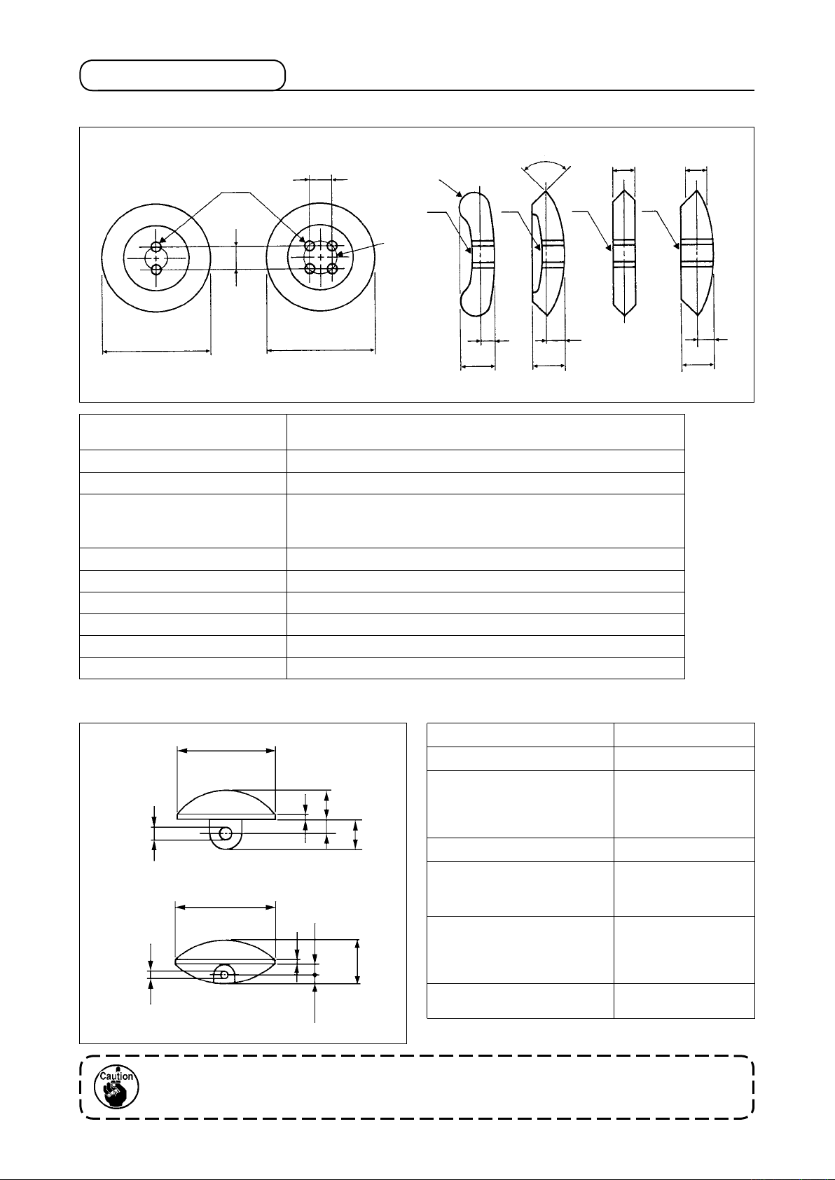
(2) Shapes of buttons
1)Specicationsfor4-holedand2-holedbuttons
B
A
C
B
2
E
1
E
G
G
G
3
E
G
3
E
D
A : Buttonhole diameter
D
F
H
Needle used : ø 1.5 mm or more when using #12 to #16
Needle used : ø 2 mm or more when using #16 to #18
F
H
B : Distance between buttonholes 1.5 to 6.0 mm (in increments of 0.1 mm)
C : Location of buttonholes All holes must be located equidistant from the center of each button.
Min. outside diameter : ø 8 mm
D : Outside diameter
Max. outside diameter : ø 32 mm
Line height : within ± 0.25 mm
E1 : Button with a round edge
R (roundness) of button edge must be a 3 mm radius or less.
E2 : Button with a V-shaped edge Within 120˚ angle
E3 : Button with an angular edge The thickness must be 5 mm or less.
F : Bulge 5 mm or less
G : Area around buttonholes Must be smooth
H : Thickness of button 8 mm or less
2)Specicationsforshankbuttonandmarblebutton
F
H
F
A : Buttonhole diameter ø 1.5 mm or more
B : Thickness of button 6.8 mm or less
C : Distance from the bottom
E
B
A
C
D
of the button head to the
center of the buttonhole
Shank button :
1 mm to 6 mm
Marble button :
1.5 mm or more
D : Length of shank 8 mm or less
E : H e i g ht of th e st r a i gh t
F
section on the side face of
3.5 mm or less
button
C
A
E
B
F : Outside diameter
Min. outside diameter:
ø 8 mm
Max. outside diameter:
ø 32 mm
G
the hole to the button edge
G : Distance from the center of
2 mm or less
When the button loader is used, there are cases where the buttons cannot be used due to the
shape. So, be careful.
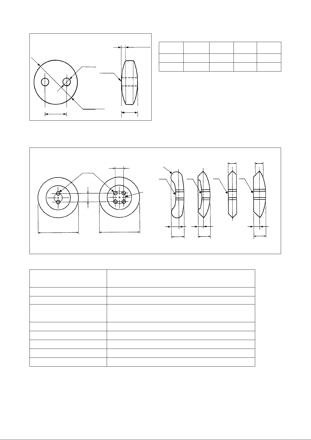
3)Specicationsforstaybutton
Buttonhole
diameter
Right
side
Outside
Buttonhole pitch
diameter
Thickness of button
4)Counterbuttonspecications
1 mm or *
less
1
Commendable dimension
Outside
diameter
Buttonhole
diameter
Buttonhole
pitch
Type A 8.5mm 2.5mm 3.1mm 2.0mm
Type B 10.2mm 3.2mm 4.0mm 2.0mm
*1 For the stay buttons, use those, the amount
of convex on the right side of which is 1 mm
or less.
Thickness
of button
2
B
1
E
E
A
G
G
G
G
C
B
D
D
F
H
F
H
Commendable dimension
A : Buttonhole diameter
B : Distance between buttonholes 1.5 to 6.0 mm
C : Location of buttonholes All holes must be located equidistant from the center of each button.
Needle used : ø 1.5 mm or more when using #12 to #16
Needle used : ø 2 mm or more when using #16 to #18
2
E
F
H
D : Outside diameter
Min. outside diameter : ø 8 mm
Max. outside diameter : ø 25 mm
E1 : Button with a round edge R (roundness) of button edge must be a 2 mm radius or less.
E2 : Button with an angular edge The thickness must be 5 mm or less.
F : Height of button edge 2 mm or less
G : Area around buttonholes Must be smooth
H : Thickness of button 5 mm or less
!
– 3
!– 4
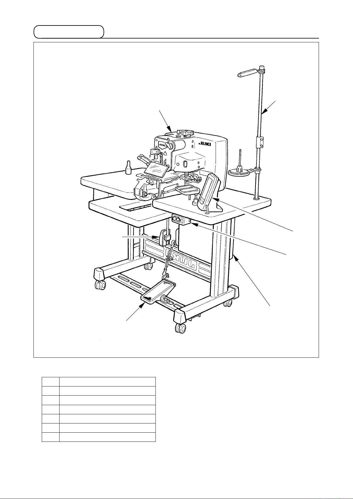
(3)Conguration
7
2
6
5
AMB-289 consists of the following components.
Power ON/OFF switch
1
Machine head (AMB-289)
2
Operation panel (IP-310D)
3
Control box (MC-640)
4
Foot pedal
5
Start switch
6
Thread stand device
7
3
1
4
2. INSTALLATION
WARNING :
To prevent possible accidents caused by the fall of the sewing machine, perform the work by two
persons or more when the machine is moved.
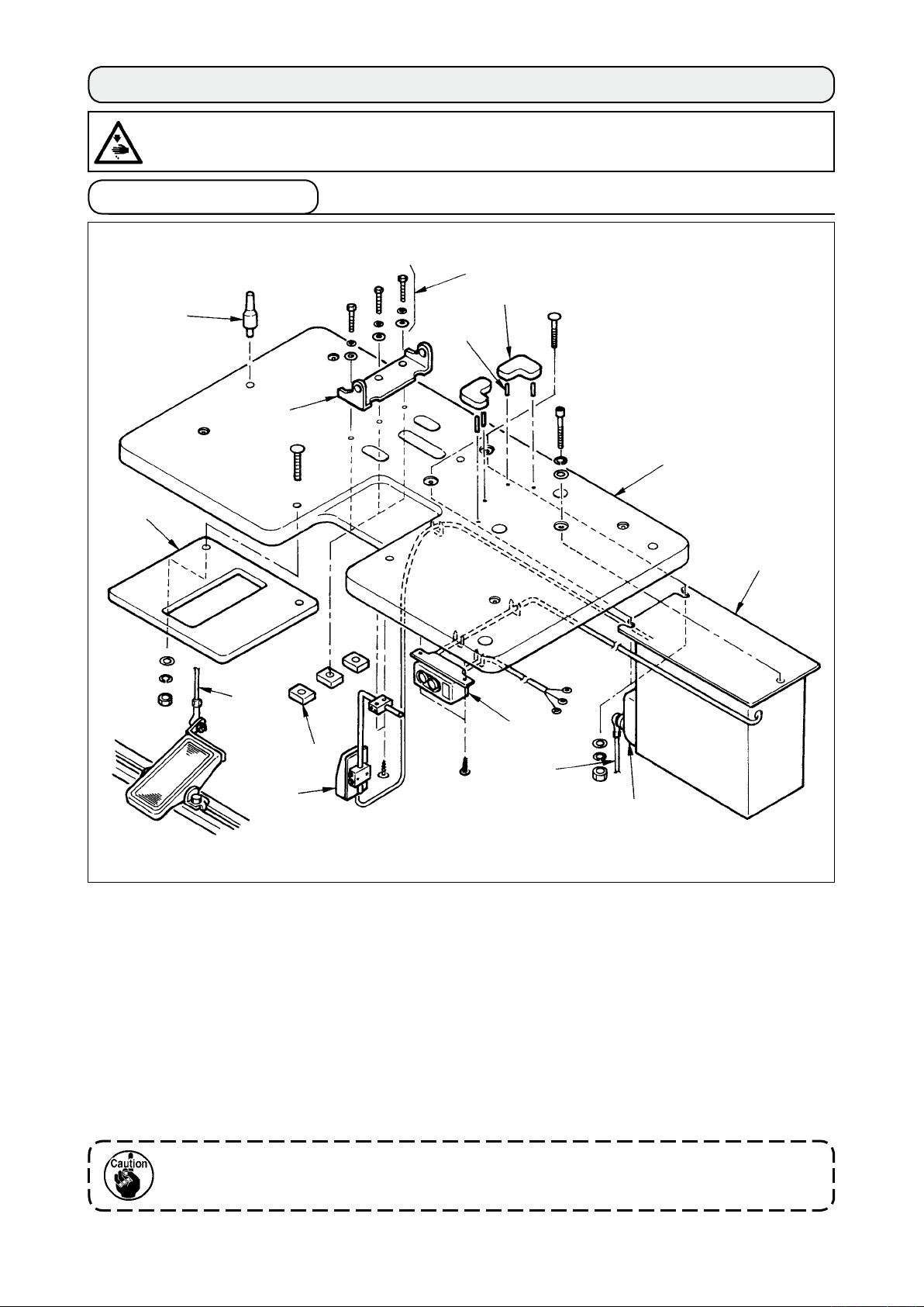
(1) Set-up of the table
8
!3
!1
7
6
5
1
2
9
3
!2
9
4
!0
1) Fix control box 2, power switch 3, auxiliary table !3 and start switch 4 to table 1.
Note) Install auxiliary table
!3
before installing start switch 4.
2) Fix the cables of power switch 3 and start switch 4 with staples.
3) Pass arm stay xing screws !1 (3 pcs.) through arm stay 5, instal on the table, and x them with
nuts !2.
4) Drive pins 6 to the table, and insert rubber cushions 7.
5) Fix head support bar 8 on table 1.
6) Connect the pedal (left-hand side) and control box pedal sensor !0 with connecting rod 9
supplied as accessories.
Adjust the positions of the pedals so that connecting rods 9 and control box 2 do not come in
contact with each other.
!
– 5
!– 6
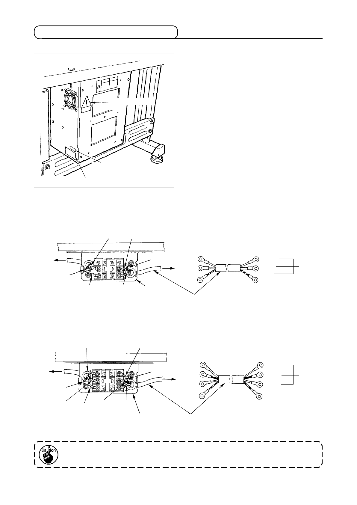
(2) Connecting the power source cord
1)Voltagespecications
Power source specications are indicated on the
voltage indication seal. (3-phase type only)
F o r o t h e r t y p e mac hi ne s , p o w e r sou r c e
specications are indicated on the voltage caution
seal and the rating label.
Voltage caution
seal
Voltage indication seal
(3-phase type
Rating label
only)
2) Connecting single phase 200V, 220V, 230V and 240V
Connect so as to supply the power to the white wire and the black wire as shown in the illustration.
Co n n ec t th e co r d in ac c or d a nc e wi t h t h e
specications.
Light blue
Table
Control box
Green/Yellow
Brown
Light blue
Brown
Green/Yellow
Plug
Power switch
3) Connecting three phase 200V, 220V and 240V
Table
Control box
Green/Yellow
Black
White
Red
Black
White
Green/Yellow
Plug
Red
Power source cord
Brown
Light
blue
Green/
Yellow
Red
White
Black
Green/
Yellow
AC200 V
AC220 V
AC230 V
AC240 V
GND
AC200 V
AC220 V
AC240 V
GND
Power switch
1. Never use under the wrong voltage and phase.
2. When changing the voltage, refer to the item of "Changing the voltage of 100 / 200V".
Power source cord

(3) Changing the voltage of 100 / 200V
WARNING :
To prevent personal injuries caused by electric shock hazards or abrupt start of the sewing
machine, carry out the work after turning OFF the power switch and a lapse of 5 minutes or more.
To prevent accidents caused by unaccustomed work or electric shock, request the electric expert
or engineer of our dealers when adjusting the electrical components.
It is adaptable to the voltage of single phase 100V to 120V/3-phase 200V to 240V by changing the
voltage changeover connector mounted on FLT p.c.b.
(Caution) When the changing procedure is wrong, the control box will be broken. So, be very
careful.
Changing procedure of the changeover connector
1. Turn OFF the power source with the power
switch after conrming that the sewing machine
has stopped.
2. Draw out the power cord from the power plug
socket after conrming that the power switch is
turned OFF. Then wait for ve minutes or more.
3. Remove the front cover.
4. Remove four screws xing the rear cover of the
control box and slowly open the rear cover.
A. In case of using with 3-phase 200V to 240V
1
A
• Changing the changeover connector
Connect to 200V the 100/200V changeover
connector of FLT p.c.b. 1 located on the side
of the Box Side of the control box.
• Connect the crimp style terminal of AC input
cord to the power plug as shown in the gure.
B
C
WHITE
BLACK
RED
GREEN/
YELLOW
WHITE
BLACK
RED
GREEN/
YELLOW
WHITE
BLACK
RED
GREEN/
YELLOW
WHITE
BLACK
RED
GREEN/
YELLOW
WHITE
BLACK
RED
GREEN/
YELLOW
WHITE
BLACK
RED
GREEN/
YELLOW
(Plug side)
(Plug side)
(Plug side)
B.
In case of using with single phase 100V to 120V
• Changing the changeover connector
Connect to 100V the 100/200V changeover
connector of FLT p.c.b. 1 located on the side
of the Box Side of the control box.
• Connect the crimp style terminal of AC input
cord to the power plug as shown in the gure.
(Caution) Securely perform the insulation
treatment to the red terminal which is
not used with insulation tape or the like.
(Whentheinsulationisinsufcient,
there is a danger of electric shock or
leakage current.)
C.
In case of using with single phase 200V to 240V
• Changing the changeover connector
Connect to 200V the 100/200V changeover
connector of FLT p.c.b. 1 located on the side
of the Box Side of the control box.
• Connect the crimp style terminal of AC input
cord to the power plug as shown in the gure.
(Caution) Securely perform the insulation
treatment to the red terminal which is
not used with insulation tape or the like.
(Whentheinsulationisinsufcient,
there is a danger of electric shock or
leakage current.)
5. Check that the change has been performed
without fail before closing the rear cover.
6. Be careful that the cord is not pinched between
the rear cover and the control box main unit.
Close the rear cover while pressing the lower
side of rear cover, and tighten four screws.
!
– 7

!– 8
(4) Installing the sewing machine main unit
WARNING :
To prevent possible accidents caused by the fall of the sewing machine, perform the work by two
persons or more when the machine is moved.
Adjust the sewing machine head to the hole of
arm stay, and insert shaft 1. Fix shaft 1 with
screws 2 in the state that the end faces of shaft
are protruded on the both sides.
1
Be careful that wiring and air pipe
coming out from the bottom face
of the se w i n g m a c h ine are n o t
2
1
crushed.
(5) Tilting the sewing machine head
WARNING :
Whentilting/raisingthe sewing machine head, perform the work so asnottoallowyour ngers to
be caught in the machine. In addition, to avoid possible accidents caused by abrupt start of the
machine, turn OFF the power to the machine before starting the work.
1
When tilting the sewing machine head, tilt quietly
the sewing machine until head support bar 1
comes in contact with it.
1. Make sure that sewing machine
head support bar 1 is placed
on the table before tilting the
sewing machine.
2. To protect fall-down, be sure to
tilt the sewing machine in a level
place.
3. Keep the table in the state that
anything is not put on the top
surface of table

(6)Removingthexedplatefortransport
2
1
[Reference]
3
2
Remove xed screw 1 and remove xed plate for
transport 2.
Fixed screw 1 and fixed plate for
transport 2 are necessary when
transporting with the machine head
sing l e unit. So, kee p them wit h
care.
In case of the complete transport
¡
In case of the complete transport, x the sewing
machine to th e table with screw 1, two flat
washers 2 and nut 3 supplied as accessories
in order to safely transport the sewing machine.
1
(7) Installing the operation panel
3
1
Fix operation panel attaching plate 1 on the
table with woodscrew 2 and pass the cable
through hole 3 in the table.
2
!
– 9

!– 10
(8) Installing the air regulator
!1
3
2
1
4
!0
5
6
7
8
9
1) Install lter installing plate 1 on the right side of the stand side support with screw 3.
2) Fix air regulator 2 on lter installing plate 1 with screw 4.
3) Fix elbow union 5 on the right section of air regulator 2.
4) Insert air hose 6 into elbow union 5.
5) Insert reducing union T 7 into the top end of the air hose, and insert stop plug 8 into the hole of
ø6.
Use the branch section (ø6) of reducing union T 7 when using the air gun.
Air gun set (G57602540A0) is available as optional.
6) Insert air tube 9 coming from the main unit of machine head into reducing union T 7.
7) Insert pressure sensor relay cord !0 into connector !1 of air regulator 2.
8) Winding pressure sensor relay cord !0 around air tube 9, insert it into the control box (CN41).
9) Supply air, and adjust the air pressure to 0.5 Mpa.

(9) Connecting the cords
Perform the connection of the cords as shown in the gure below.
CN14
CN16
Sewing machine head
MAIN
circuit
board
CN33
CN34
SDC circuit board
CN16
CN16
CN14
SDC circuit board
CN14
1
CN38
CN39
CN40
CN41
Cord
clamp A
CN43
CN44
CN33
CN38
Start
switch
CN39
CN40
CN43
CN44
CN34
CN41
Operation panel
Filter regulator
1) Pass 5 c ords ( CN39, 4 0, 41, 4 3 and 4 4 )
connecting to the right side among the cords
connecting to MAIN circuit board through cord
clamp A as shown in the gure, and connect
them to the respective connectors. Connect
CN38 to the conne c t o r wi t h o u t pa s s i n g
through cord clamp A.
2) Directly connect two cords connecting to the
left side of MAIN circuit board to CN33 and
CN34.
3) Connect the cords connecting to SDC circuit
board directly to CN14 and CN16.
4) Fix the earth wire with the setscrew 1.
!
– 11

!– 12
(10) Managing the cord
1) Slowly tilting the sewing machine, check that the cords are not forcibly pulled.
2) Fix the cords with cord setting plate 1 as shown in the gure.
When you tilt the sewing machine, make sure that the sewing machine head
support bar 2 is placed on the table.
2
1
(11)Installingtheeyeprotectioncoverandthengerguard
WARNING :
Be sure to attach this cover to protect the eyes from the disperse of needle breakage.
Be sure to install eye protection cover 1 and
nger guard 2, and use the sewing machine.
1
2

(12) Installing the thread stand
2
1
(13) Attaching the button tray
1) Assemble the thread stand, and set it in the
hole in the top right corner of the machine
table.
2) Tighten locknut 1 to x the thread stand.
3) When ceiling wiring is possible, pass the
power cable through spool rest rod 2.
1) Fix base 1 on the table with wood screw 2.
2) Insert button tray 4 in the hole of base 1
and fix it with setscrew 3 after adjusting
the position to that where the button can be
taken with ease.
4
3
1
2
I t i s p o ss i bl e t o c h an g e t h e
lo a d er set po s i ti o n a s we l l . It
i s r e c o m me n d ed to pe r f o rm
positioning them together.
(Memory switch U04)
!
– 13

!– 14
3. PREPARATION BEFORE OPERATION
(1) Inserting the needle
WARNING :
To protect against possible personal injury due to abrupt start of the machine, be sure to start the
following work after turning the power off and ascertaining that the motor is at rest.
Hold needle with its recessed part facing toward
side
"A"
machine, insert the needle into the needle hole
of needle bar until it will go no further, and tighten
setscrew 1 with a at-blade screwdriver.
Use a SM332EXTLG-NY(#11 to #18).
2
2
3
3
1
1
A
as observed from the front of the sewing
When attaching the needle, turn
OFF the power to the motor.
Attach stop plug 2 supplied as
accessories (insert magnet 3
supplied as accessories into
the top end) to the needle. It is
recommendedtoconrmthatthe
needle is vertical.
(2) Threading the needle-thread
WARNING :
To protect against possible personal injury due to abrupt start of the machine, be sure to start the
following work after turning the power off and ascertaining that the motor is at rest.
Pass the needle thread in the order 1 to !3 as shown in the gures.
2
3
4
9
!0
7
1
5
!1
8
!3
!2
6

(3) Adjusting the stay (counter) button stopper
WARNING :
To protect against possible personal injury due to abrupt start of the machine, be sure to start the
following work after turning the power off and ascertaining that the motor is at rest.
Loosen screws 3 and adjust so that the clearance
between stopper 1 and pin 2 is 0.5 to 1 mm with
the button used set. Then x the stopper.
2
6
4
5
0.5 to 1mm
3
1
1. The size applicable to the stay
bu t t o n is ø8 to ø 2 5 , a n d th e
thickness is 2 mm or less.
2. Feed plate is made so as to make
it easy to set the stay button of ø8
to ø10. Replace the feed plate with
the feed plate for counter button
when using the button which is not
clamped with stay button clamps
and 6, or using the button, the
5
needle entry position of which is
notttothewindowofgauge
4
.
[Reference]
6
5
Counter button B set
(40021447)
6
4
7
5
7
To change the feed plate to the feed plate
for counter button, there are two kinds of
methods ; changing as a set and replacing the
components.
In case of replacing as a set
¡
1) Purchase the set (40020807) of feed plate
for counter button. Loosen two screws 8
and replace the feed plate.
In case of replacing the components
¡
1) P u rch a s e th e c o unt e r bu t ton B se t
(40021447), loosen two screws 8, and
remove the feed plate from the machine
head.
2) Replace the components 4, 5, 6, and
with counter button B set (40021447).
7
4
8
8
3
1
!
1. Maximum size to be applied is
ø25.
2. When installing the feed plate,
insert it until it goes no further
andxit.
– 15

!– 16
(4) Replacing the button chuck
WARNING :
To protect against possible personal injury due to abrupt start of the machine, be sure to start the
following work after turning the power off and ascertaining that the motor is at rest.
1
3
2
<Button chuck correspondence table>
When replacing chuck 1, loosen screws 2 and
replace it with exclusive screwdriver 3 supplied
as accessories.
Part No. Description
40020932
40020931 Button chuck (medium) (standard) ø 14 to 25 mm Installed on machine head
40020930 Button chuck (large) ø 25 to 38 mm Accessory
Button chuck (small) ø 8 to 16 mm
Outside diameter of button
that can be used
Remarks
Accessory

(5) Set of the button neck wrapping
1
Groove B
Groove
A
Groove A
2
Groove
B
3
Height of
button neck
wrapping
5
Whe n perfo rming the but ton nec k wrapp ing
process of stay (counter) button, use the button
neck wrapping attachment (accessories) 1.
Loosen screws 2 and move holder plate 3 to
and fro to perform the adjustment of the height of
button neck wrapping attachment.
Conrmthatbuttonneckwrapping
positioning grooves A and B are
straight front and rear.
[Setting procedure of the button neck wrapping
attachment]
Insert convex 4 of the attachment to concave 5
of the feed plate at the time of the button neck
wrapping process pattern.
4
(6)Setofthesewingatbuttonwithblindstitch
When performing the sewing flat button with
2
1
blindstitch, insert underplate spacer A 1 supplied
as accessories (Part No. : 40020764) to the pin
position. In addition, fix it with screws 2 when
using it always.
Select and use a proper underplate spacer from
among the underplate spacers below according to
the thickness of cloth.
Discription
UNDER_PLATE_
SPACER A
UNDER_PLATE_
SPACER B
UNDER_PLATE_
SPACER C
Thickness
t=1.6 40020764 Accessory
t=2.0 40020769 Optional
t=2.6 40020770 Optional
Part No. Remarks
!
– 17

!– 18
4. ADJUSTMENT OF THE SEWING MACHINE
(1) Adjusting the needle and the looper
1) Adjusting the needle bar height
Use the timing gauge supplied as accessories.
Loosen screw
1
case of SM332EXTLG-NY (standard needle) or
plane
in case of SM332SUPLG-NY aligns with
B
the height of the throat plate when the needle bar
comes down to the lowest position.
and adjust so that plane
1
A
in
Perf o r m the a d j ustme n t a t t h e
needle rocking origin (marker line).
Marker
line
To align
A
29.6mm
34.6mm
B
[Needle list]
JUKI Part No. Needle Part No.
MSM3AAN1100 NEEDLE SM332EXTLG-NY #11
MSM3AAN1200 NEEDLE SM332EXTLG-NY #12
MSM3AAN1400 NEEDLE SM332EXTLG-NY #14
MSM3AAN1600 NEEDLE SM332EXTLG-NY #16
MSM3AAN1800 NEEDLE SM332EXTLG-NY #18
MSM3ABN1100 NEEDLE SM332SUPLG-NY #11
MSM3ABN1200 NEEDLE SM332SUPLG-NY #12
MSM3ABN1400 NEEDLE SM332SUPLG-NY #14
MSM3ABN1600 NEEDLE SM332SUPLG-NY #16
MSM3ABN1800 NEEDLE SM332SUPLG-NY #18
2) Adjusting the clearance between the needle and the looper
Use the timing gauge supplied as accessories.
Loosen two screws 1, move looper 2 and adjust
by loosening screw 4 so that the clearance
D
between the needle and the blade tip of looper
is 0.05 to 0.1 mm when plane C in case of
SM332EXTLG-NY (standard needle) or plane D in
case of SM332SUPLG-NY aligns with the height
C
37.6mm
of the needle bar.
In addition, adjust so that the left position of
needle 3 aligns with the top end of looper 2 as
32.6mm
observed from the front.
1
4
0.05 to 0.1mm
2
3
2
To align

(2) Adjusting the position of the york slide
1
1
0 to 0.2mm
2
0.2 to 0.4mm
Fig. 1
Approx. 6mm
1) The position of york slide
has been factory-
1
assembled so that the clearance between
york slide 1 and the needle is longitudinally
0.2 to 0.4 and laterally 0 to 0.2 mm when the
needle bar comes to the lowest position.
(Refer to Fig. 1.)
2) Adjust the lateral position of york slide
1
by
loosening setscrews 2 and moving york slide
laterally.
1
3) Adjust the longitudinal position of york slide
by loosening setscrew 3 and moving york
1
slide cam 4 longitudinally. The motion timing
of york slide cam 4 at this time is adjusted
by making the engraved marker line on york
slide cam 4 directly below and tightening the
cam with setscrew 3 when the needle bar is
at the lowest position.
4) Timing of the york slide motion is performed
in the order that the york slide moves from
the left to the right and starts retracting
immediately after the blade tip of looper has
passed the triangle of the thread.
(Posi tion w here t he need le bar goes u p
approximately 6 mm from the lowest position)
5) Loosen setscrews 7 in york slide triangle
cam 6 and turn the cam in the direction of
rotation to perform this adjustment.
5
6
Blade tip of looper
Locus of york slide
3
4
Marks made by the electron pen have
been put on york slide cam 4 and
york slide triangle cam 5 at the time
of delivery from factory. Make them
as the standard of timing adjustment.
6) For the locus of york slide motion, loosen
setscrew 4 in york slide cam 5 and turn
the cam in the direction of rotation to adjust
so that the locus becomes a triangle while
keeping the clearance (0 to 0.2 mm) between
the n e e dle and the y o r k slide when t h e
needle goes up.
!
– 19

!– 20
(3) Adjusting the needle and the needle guide
1) Adjusting the position of the needle and the throat plate
Loosen screws 1 and adjust the throat plate so
that the needle enters the center of the needle
1
Center
2) Adjusting the clearance between the needle and the needle guide
hole.
0 to 0.1mm
Loosen screw 1 and adjust so that the clearance
between needle guide 2 and the needle is 0 to 0.1
mm at the lowest position of the needle bar.
1
2

(4) Adjusting the thread trimmer mechanism
1) Adjusting the position of the moving knife
First adjustment
0
1
2
1
3
13 to 14 mm
2
3
Second adjustment
5
4
7
3 to 5 mm
[Waiting position]
1. L o o s e n s c r ew s 1 a nd c l o s e t h e
clearance with stopper 2 so that the
dimension between the edge of fixed
knif e link 3 a nd the gro o ve end o f
throat plate is 13 to 14 mm. Then fix
screws 1.
[Thread trimming position]
1. Adjust the clearance between the blade point
of moving knife 7 and the right end of the slot
of throat plate is 3 to 5 mm in the state that
air only is ON (solenoid valve No. 14), loosen
screws 5, actuate the cylinder, and x screws
5
2. After the adjustment, check that moving knife
link 4 smoothly moves.
2) Adjusting the moving knife thread separation nail
Top end of thread separation nail
B e n d t hr ea d se p a r a t i o n n a i l 1 u si ng a
screwdriver or the like and adjust so that a
0.5 to 0.7mm
1
clearance of 0.5 to 0.7 mm should be provided
between thread separation nail 1 and looper 2.
in the state that the clearance is closed.
When the work is
completed, do not
forget to perform the
release of lock 6 of
the solenoid valve.
6
2
!
– 21

!– 22
(5) Adjusting the wiper mechanism
8
9
!0
4
7
5
3
6
1
1) Turn OFF the air, and draw wiper 1 until it
goes no further.
2) Adjust wiper cylinder installing bases A 3
and B 4 with the respective setscrews
and 6 so that the vertical clearance
5
between needle tip 2 and the top surface
of wiper 1 is 3 to 5 mm and the lateral
dimension between needle tip 2 and the
thread holding section of wiper 1 is 6 to
8 mm at the sewing machine stop position
(needle bar upper dead point).
3) Fix spring A 7 so that wiper 1 and spring A
equally come in contact with each other
7
on the plane within the range of the stroke
of cylinder 8.
4) Adjust th e hol ding force of thread w ith
spring B 9.
5) To adjust the holding force, loosen screw
and adjust so that thread slips off with
!0
the force of approximately 20 to 25g when
polyester spun thread #50 is held.
2
3 to 5mm
1
6 to 8mm
(6) Adjusting the chuck open mechanism
3
1
When the mode is changed over to the manual
button control mode, raise hook A 1 to decrease
the open amount. Adjust the open amount by
loosening screws 2 and sliding hook B 3 to the
right and left.
2
When the mode is changed over to
the button loader motion mode, do
not forget to release hook A 1.

5. MAINTENANCE
(1) Replacing the attachments
1) Replacing the button set pin (optional)
1
2
B
4
When replacing button set pin 2, loosen knob 1
and replace it. However, when replacing the set
pin with those below, remove knob 1 and install it
in the screw hole on side B.
1
2
3
4
No. Part No. Description
1
2
3
4
17974056
17974254
17974452
40023428
Set pin for marble button
Set pin for shank button (ø 1.5 to ø 2.0)
Set pin for shank button (ø 2.0 or more)
Set pin for metallic button
3
0.3 to
0.7 mm
2) Replacing the carrier pin
When replacing carrier pin 4, loosen screws 3 and replace it.
At this time, adjusdt the height of the carrier pin to 0.3 to 0.7 mm from the top surface of the set pin.
<Carrier pin list>
Button carrier (for 4-holed button) Button carrier (for 2-holed button)
1 2 3 4 5
ø b
a
a
ø b
a
a
ø b
a
a
a
a
ø b
ø b
Stamp
A
B
C
Part No.
17856600
17856709
17856808
Dimensions
a 2.0
b 1.0 b 1.2 b 1.4 b 1.0 b 1.4
a 2.4
b 1.2 b 1.4 b 1.8 b 1.2 b 1.4
a 2.6
b 1.2 b 1.2 b 1.8 b 1.2 b 1.4
Stamp
D
E
F
F1
G
H
J
Part No.
17856907
17857004
17857103
17857202
17857301
Standard
spec
17857400
17857509
Dimensions
a 2.8
a 2.8
a 3.0
a 3.0
b
a 3.2
b
a
b 1.4 b 1.4 b 1.4
a 3.6
b
1.4
1.4
3.4
1.4
Stamp
K
K1
L
Part No.
17857608
17857707
17857806
!
– 23
Dimensions
a 4.0
a 4.0
a 5.0
Stamp
M
N
P
Q
R
S
T
Part No.
17858002
17858101
17858200
17858309
17858408
17858507
Standard
spec
17858606
Dimensions
a 2.0
a 2.4
a 2.6
a 2.8
b
a 3.0
b
a
a 3.4
b
Stamp
1.2
1.2
3.2
1.4
U
V
W
X
Y
Z
Part No.
17858705
17858804
17858903
17859000
17859109
17859208
Dimensions
a 4.0
a 4.2
a 4.4
a 4.6
b
a 4.8
b
a
1.4
1.4
5.0

!– 24
3) Replacing the tongue stopper
2
1
5
4
When using the standard 4-holed tongue (Part
No. 25006602) of the former AMB-189N, replace
the tongue stopper guide together.
1) Replacing the tongue
Remove screws 1 and replace tongue 2.
2) Replacing the tongue stopper guide
Remove screws 3 and replace tongue stopper
guide 4 with tongue stopper guide B (Part No.
: 40020763) 5 supplied as accessories.
3
3) Finally, perform the change of memory switch
level K12.

(2) Replacing the fuse
WARNING :
1. To avoid electrical shock hazards, turn OFF the power and open the control box cover after about
veminuteshavepassed.
2. Open the control box cover after turning OFF the power without fail. Then, replace with a new
fusewiththespeciedcapacity.
1
2
3
The machine uses the following three fuses :
For pulse motor power supply protection
1
5A (time-lag fuse)
Fo r sol enoid and pulse moto r pow er
2
supply protection
3.15A (time-lag fuse)
For control power supply protection
3
2A (fast-blow type fuse)
!
– 25

!– 26
(3) Greasing parts
WARNING :
Turn OFF the power before starting the work so as to prevent accidents caused by abrupt start of the
sewing machine.
Periodically perf orm grease-up every 6 mon ths as a s tanda rd, or per form grease-up when
(grease-up time) is displayed on the operation panel.
There are three kinds of the exclusive greases supplied as accessories.
Grease in grease tube (green, Part No. 13525506)
○
Greasing section
of rack and gear
Apply grease to rack, gear and cam section.
→
1) Remove the rear cover, and apply grease to
rack and gear section of Y top feed.
Greasing section of
rack on the front side
Greasing section of
rack on the rear side
2) Remove the rear cover and the side cover,
and apply grease to rack and gear section
of Y bottom feed.
• Move the bottom unit to the extreme front,
and apply grease to the front section of the
rack section.
• Move the bottom unit to the extreme rear,
and apply grease to the rear section of the
rack section.

3) Apply grease to the york slide cam and the
york slide triangle cam sections.
• Tilt the machine head
• Remove the looper cover.
• Turning the hand pulley, apply grease to the
lateral cam section.
For t he grea s ing sect ion of t h e
yoke slide cam, use grease in JUKI
grea s e A tu b e ( w hite, Pa r t No.
40006323).
Greasing
section of the
yoke slide
triangle cam
Grease in JUKI grease B tube (white, Part No. 40013640)
○
Remove the top cover and apply grease to the worm section.
→
Greasing
section of the
yoke slide cam
• Use the groove of top surface of worm,
Worm and worm
wheel section
turning with the atblade screwdriver, apply
grease to moving parts of the worm and
worm wheel.
Grease in JUKI grease A tube (white, Part No. 40006323)
○
Apply grease to other parts such as rotation fulcrum section, link moving section, etc.
→
(Caution) 1. When applying grease, apply new grease after carefully wiping old grease with a
piece of cloth or the like.
2. When the air gun or the like is blown to the greasing parts and the grease is
scattered, perform grease-up again.
!
– 27

!– 28
6. AIR CIRCUIT DIAGRAM
4
1
2
K
R
A
M
E
R
I
W
2
0
0
7
3
0
8
1
5
5
4
2
2
K
R
A
M
E
R
I
W
1
0
1
7
3
0
8
1
6
5
4
3
2
K
R
A
M
E
R
I
W
0
0
2
7
3
0
8
1
7
5
4
4
2
K
R
A
M
E
R
I
W
9
0
3
7
3
0
8
1
8
5
4
5
2
K
R
A
M
E
R
I
W
8
0
4
7
3
0
8
1
9
5
4
6
2
K
R
A
M
E
R
I
W
7
0
5
7
3
0
8
1
0
6
4
7
2
K
R
A
M
E
R
I
W
6
0
6
7
3
0
8
1
1
6
4
8
2
K
R
A
M
E
R
I
W
5
0
7
7
3
0
8
1
2
6
4
9
2
K
R
A
M
E
R
I
W
4
0
8
7
3
0
8
1
3
6
4
1
3
K
R
A
M
E
R
I
W
0
0
0
8
3
0
8
1
4
6
4
3
3
K
R
A
M
E
R
I
W
8
0
2
8
3
0
8
1
5
6
4
4
3
K
R
A
M
E
R
I
W
7
0
3
8
3
0
8
1
6
6
4
5
3
K
R
A
M
E
R
I
W
6
0
4
8
3
0
8
1
7
6
4
6
3
K
R
A
M
E
R
I
W
5
0
5
8
3
0
8
1
8
6
4
7
3
K
R
A
M
E
R
I
W
4
0
6
8
3
0
8
1
9
6
4
8
3
K
R
A
M
E
R
I
W
3
0
7
8
3
0
8
1
0
7
4
9
3
K
R
A
M
E
R
I
W
2
0
8
8
3
0
8
1
1
7
N
O
I
T
P
I
R
C
S
E
D
.
O
N
T
R
A
P
.
o
N
Y
T
'
Q
1 7
8
1
9
1
0
0
4
R
O
T
A
L
U
G
E
R
R
E
T
L
I
F
1
2 5
9
1
9
1
0
0
4
Y
S
S
A
H
C
T
IW
S
R
E
V
K
C
U
H
C
1
3 6
9
1
9
1
0
0
4
Y
S
S
A
H
C
T
I
W
S
R
O
H
K
C
U
H
C
1
4 7
9
1
9
1
0
0
4
Y
S
S
A
T
C
I
W
S
P
U
D
E
E
F
1
5 8
9
1
9
1
0
0
4
Y
S
S
A
H
C
T
I
W
S
N
W
O
D
D
E
E
F
1
6 9
9
1
9
1
0
0
4
Y
S
S
A
H
C
T
I
W
S
N
E
P
O
E
U
G
N
O
T
1
7 2
0
0
1
2
0
0
4
Y
S
S
A
E
V
L
A
V
D
I
O
N
E
L
O
S
1
8
B
E
1
0
1
0
8
1
0
T
B
m
1
E
S
O
H
E
B
U
T
9
B
E
1
5
2
0
0
4
0
T
B
m
2
1
E
S
O
H
E
B
U
T
0
1
B
E
1
0
5
0
0
8
0
T
B
m
2
E
S
O
H
E
B
U
T
1
1
0
A
0
9
0
3
1
0
3
2
G
1
R
E
D
N
I
L
Y
C
R
I
A
2
1
0
A
4
0
5
0
0
6
0
A
P
1
R
E
D
N
I
L
Y
C
R
I
A
3
1
0
A
1
0
5
1
0
8
0
A
P
2
R
E
D
N
I
L
Y
C
R
I
A
4
1
0
A
0
1
0
2
0
0
1
A
P
2
R
E
D
N
I
L
Y
C
R
I
A
5
1
0
A
1
1
0
2
0
0
1
A
P
1
R
E
D
N
I
L
Y
C
R
I
A
6
1
0
A
2
0
5
7
0
0
1
A
P
1
R
E
D
N
I
L
Y
C
R
I
A
7
1
0
A
2
0
5
2
0
5
1
A
P
1
R
E
D
N
I
L
Y
C
R
I
A
8
1
0
B
6
0
0
2
0
6
1
A
P
1
R
E
D
N
I
L
Y
C
R
I
A
9
1
0
A
8
0
0
2
0
6
1
A
P
1
R
E
D
N
I
L
Y
C
R
I
A
0
2
0
A
6
0
5
1
0
0
2
A
P
1
R
E
D
N
I
L
Y
C
R
I
A
1
2
0
0
0
6
0
4
2
1
0
C
P
R
E
L
L
O
R
T
N
O
C
D
E
E
P
S
4
2
2
0
0
E
3
0
4
2
2
0
C
P
3
G
N
I
R
T
R
E
S
N
I
3
2
3
0
5
2
5
0
6
4
0
J
P
3
W
O
B
L
E
E
S
O
H
4
2
0
1
0
4
0
3
0
1
2
J
P
2
N
O
I
N
U
F
L
A
H
5
2
5
0
0
0
4
0
3
0
3
J
P
5
N
O
I
N
U
6
2
1
0
3
0
2
0
4
0
3
J
P
6
W
O
B
L
E
7
2
4
0
5
0
4
0
4
0
3
L
P
7
N
O
I
N
U
W
O
B
L
E
8
2
1
0
2
5
8
0
4
0
3
J
P
1
N
O
I
N
U
W
O
B
L
E
9
2
1
0
0
0
2
0
5
0
3
J
P
2
T
N
I
O
J
T
0
3
1
0
0
0
8
0
5
0
3
J
P
1
E
E
T
E
P
I
P
1
3
2
0
0
0
4
0
8
0
3
J
P
G
N
I
L
P
U
O
C
K
C
I
U
Q
1
2
3
2
0
5
0
4
0
1
0
3
J
P
4
W
O
B
L
E
E
S
O
H
3
3
0
0
0
4
1
0
0
5
X
P
6
G
U
L
P
4
3
0
0
0
1
0
0
0
5
9
X
P
1
G
U
L
P
4
1
K
R
A
M
E
R
I
W
6
0
0
5
3
0
8
1
5
3
4
2
K
R
A
M
E
R
IW
5
0
1
5
3
0
8
1
6
3
4
3
K
R
A
M
E
R
I
W
4
0
2
5
3
0
8
1
7
3
4
4
K
R
A
M
E
R
IW
3
0
3
5
3
0
8
1
8
3
4
5
K
R
A
M
E
R
I
W
2
0
4
5
3
0
8
1
9
3
4
6
K
R
A
M
E
R
I
W
1
0
5
5
3
0
8
1
0
4
4
7
K
R
A
M
E
R
I
W
0
0
6
5
3
0
8
1
1
4
4
8
K
R
A
M
E
R
I
W
9
0
7
5
3
0
8
1
2
4
4
9
K
R
A
M
E
R
I
W
8
0
8
5
3
0
8
1
3
4
4
0
1
K
R
A
M
E
R
I
W
7
0
9
5
3
0
8
1
4
4
4
1
1
K
R
A
M
E
R
I
W
4
0
0
6
3
0
8
1
5
4
4
2
1
K
R
A
M
E
R
I
W
3
0
1
6
3
0
8
1
6
4
4
3
1
K
R
A
M
E
R
I
W
2
0
2
6
3
0
8
1
7
4
4
4
1
K
R
A
M
E
R
I
W
1
0
3
6
3
0
8
1
8
4
4
5
1
K
R
A
M
E
R
I
W
0
0
4
6
3
0
8
1
9
4
4
6
1
K
R
A
M
E
R
I
W
9
0
5
6
3
0
8
1
0
5
4
7
1
K
R
A
M
E
R
I
W
8
0
6
6
3
0
8
1
1
5
4
8
1
K
R
A
M
E
R
I
W
7
0
7
6
3
0
8
1
2
5
4
9
1
K
R
A
M
E
R
I
W
6
0
8
6
3
0
8
1
3
5
4
0
2
K
R
A
M
E
R
IW
5
0
9
6
3
0
8
1
4
5
E
V
I
R
D
R
E
M
M
I
R
T
D
A
E
R
H
T
E
S
A
E
L
E
R
D
A
E
R
H
T
E
V
I
R
D
D
A
E
R
H
T
N
O
I
S
N
E
T
E
V
I
R
D
E
V
I
R
D
1
.
o
N
N
O
I
S
N
E
T
D
A
E
R
H
T
.
M
S
A
N
U
G
R
I
A
)
P
O
(
W
O
L
B
R
I
A
E
V
I
R
D
R
E
P
I
W
N
O
I
S
R
E
V
N
I
K
C
U
H
C
L
A
C
I
T
R
E
V
E
V
I
R
D
N
O
I
S
R
E
V
N
I
K
C
U
H
C
L
A
T
N
O
Z
I
R
O
H
E
V
I
R
D
E
V
I
R
D
N
E
P
O
/
E
S
O
L
C
K
C
U
H
C
H
T
O
L
C
H
C
T
I
T
S
D
N
I
L
B
E
V
I
R
D
R
E
S
S
E
R
P
E
V
I
R
D
R
E
S
S
E
R
P
H
T
O
L
C
N
O
T
T
U
B
T
A
L
F
/
E
S
O
L
C
E
U
G
N
O
T
E
V
I
R
D
N
E
P
O
E
V
I
R
D
L
A
C
I
T
R
E
V
E
U
G
N
O
T
2
2
2
2
2
2
4 2
2
3
1450
10
0
0
7
4
0
9
4
0
5
4
0
6
4
0
0
6
0
8
5
0
9
6
0
9
6
180
180
0
7
0
5
0
8
1
0
8
1
0
2
1
0
7
0
5
0
0
1
0
5
1
0
5
1
0
2
8
0
0
9
0
5
1
0
3
7
0
0
1
0
5
6
0
2
4
0
2
8
0
9
7
0
6
5
0
6
5
8
2
3
6
2
7
2
5
2
0
1
8
3
9
8
8
8
8
2
7
2
2
3
4
3
1
3
3
2
7
2
1
1
2
1
5
2
5
2
9
3
8
3
5
1
6
1
3
1
4
1
4
1
4
2
5
4
1
2
9
2
8
2
7
2
8
2
1
2
3
4
121
1
1
9
8
765
4
6
3
P
6
2
8
1
7
1
2
2
1
2
1
2
6
1
4
1
6
2
4
1
9
2
1
1
2
1
3
3
7
1
5
1
3
2
6
1
9
2
3
3
1
6
2
3
1
6
2
2
8
1
7
2
9
1
0
2
7
2
6
0
7
0
7
1
2
7
1
5
2
3
151
2
1
1
1
0
1
957
8
7
7
2
5
2
3
1
0
7
0
7
6
5
4
3
2
1
9
0
1
0
2
9
1
8
1
4
2
3
2
2
2
4
3
0
1
0
3
0
1
7
1
9
1
3
3
1
3
5
3
8
6
4
2
0
2
3
2
3
3
1
3
5
3
4
3
7
3
6
3
7
3
6
6
7
6
4
6
5
6
2
6
1
6
3
6
1
7
0
7
9
5
0
6
7
5
3
5
6
5
5
5
8
5
5
4
6
4
4
5
2
5
1
5
8
4
7
4
0
5
9
4
0
4
3
4
4
4
8
3
6
3
7
3
5
3
2
4
1
4
9
3
9
6
8
6

7. DRAWING OF THE TABLE
(1) Table
C1(Full periphery)
Part No. : 40020990
C1(Full periphery)
Top
surface
17 drilling
30 spot facing
4x4 drilling, depth 15
16 drilling
30 spot facing
Painting
4x2 drilling, depth 10
30 drilling
surface, depth 10
4x2 drilling on the bottom
Painting
3x10 drilling
16 drilling
!
2x10 drilling
– 29
6x2 drilling on the bottom surface, depth 10
Painting
JUKI logotype (by printing supplied by JUKI)

(2) Auxiliary table
Part No. : 17971805
15
40
20
All-round R2
All-round R2
2-11drilling
20
415
360
10
20
335
10
315
10
10
165
265
20
430
60
!– 30
Contents
ContentsContentsContents
 Loading...