

Page 1

AB-1360
INSTRUCTION MANUAL
* "CompactFlash(TM)" is the registered trademark of SanDisk Corporation, U.S.A.
Page 2

CONTENTS
I. MACHINE (ABOUT THE SEWING MACHINE) ......................1
Precautions for use .................................................................................................. 1
1. Conguration ........................................................................................................ 2
2. Specications ....................................................................................................... 3
2-1. Mechanical specications .............................................................................................. 3
2-2. Electrical specications ................................................................................................. 4
2-3. Shoelace specications ................................................................................................. 4
3. Installation ............................................................................................................ 5
3-1. Removing the packing materials ................................................................................... 5
3-2. Fixing the machine .......................................................................................................... 6
3-3. Connecting the air coupler ............................................................................................. 6
3-4. Connecting the power plug ............................................................................................ 7
3-5. Assembling the thread stand and installing on the machine ..................................... 7
3-6. Installing the machine head support bar ...................................................................... 7
3-7. Installing the operation panel IP-420 ............................................................................. 8
3-8. Installing the 3-pedal unit ............................................................................................... 8
3-9. Installing the additional marking light (optional) ......................................................... 9
4. Preparation of the sewing machine .................................................................. 10
4-1. Lubrication ..................................................................................................................... 10
4-2. Attaching the needle ..................................................................................................... 10
4-3. Threading the machine head ....................................................................................... 11
4-4. Installing and removing the bobbin case ................................................................... 11
4-5. Installing the bobbin ..................................................................................................... 12
4-6. Adjusting the thread tension........................................................................................ 12
4-7. Adjusting the thread take-up spring............................................................................ 13
4-8. Example of the thread tension ..................................................................................... 13
4-9. Installing the ejected loop receiver ............................................................................. 13
5. Operating the sewing machine ......................................................................... 14
5-1. Emergency stop switch ................................................................................................ 14
(1) Method for operating the emergency stop switch ....................................................................... 14
(2) Precautions with the emergency stop switch .............................................................................. 14
5-2. Winding a bobbin .......................................................................................................... 15
(1) To wind a bobbin while the sewing machine is performing sewing ............................................. 15
(2) To wind a bobbin independently .................................................................................................15
5-3. Thread clamp device ..................................................................................................... 16
5-4. Placing a shoelace loop ............................................................................................... 17
5-5. Adjusting the shoelace loop tension........................................................................... 17
5-6. Method for changing the loop width ........................................................................... 18
5-7. Start switch .................................................................................................................... 19
5-8. Adjusting the heat cutter temperature ........................................................................ 20
i
Page 3

II. OPERATION (OPERATION PANEL) ...................................21
1. Introduction ........................................................................................................ 21
2. Method for using the operation panel .............................................................. 25
2-1. Name of each section of IP-420 ................................................................................... 25
2-2. Buttons to be used in common ................................................................................... 26
2-3. Basic operation of IP-420 ............................................................................................. 27
2-4. LCD section when the shoelace loop individual sewing is selected ....................... 28
(1) Shoelace loop individual sewing data entry screen .................................................................... 28
(2) Shoelace loop individual sewing screen ..................................................................................... 30
2-5. How to change the shoelace loop length ................................................................... 32
(1) How to change the shoelace loop dimensions ...........................................................................32
(2) Changing the shoelace loop length (entire length) and precautions to be taken ........................ 33
2-6. How to lower the garment body presser and the work clamp foot .......................... 34
2-7. Using counter ................................................................................................................ 35
(1) Setting procedure of the counter ................................................................................................35
(2) Count-up releasing procedure ....................................................................................................38
(3) How to change the counter value during sewing ........................................................................ 38
2-8. How to register a new shoelace loop pattern number ............................................... 39
2-9. How to name a shoelace loop pattern number .......................................................... 41
2-10. How to select a shoelace loop pattern number ......................................................... 42
(1) Selection on the data entry screen .............................................................................................42
(2) Selection by the direct button .....................................................................................................43
2-11. How to copy a shoelace loop pattern number ........................................................... 44
2-12. How to carry out the step operation............................................................................ 45
(1) Setback step operation ............................................................................................................... 46
(2) Sewing position step operation ................................................................................................... 46
2-13. Function of canceling of a loop clamping for the next sewing ................................ 48
2-14. How to carry out the bartacking setting ..................................................................... 49
2-15. LCD section at the time of setting the bartacking ..................................................... 50
(1) LK unit data entry screen ............................................................................................................ 50
(2) LK unit sewing screen .................................................................................................................52
2-16. How to select the sewing shape (bartacking setting) ............................................... 54
2-17. List of sewing shapes ................................................................................................... 55
2-18. How to change the item data (bartacking setting) ..................................................... 56
2-19. How to check the sewing shape .................................................................................. 57
2-20. How to change the thread tension command from needle entry point to needle en-
try point .......................................................................................................................... 58
(1)
How to add/change the thread tension command from needle entry point to needle entry point ....... 58
(2) How to delete the thread tension command from needle entry point to needle entry point ........ 59
2-21. How to register a new user-pattern ............................................................................. 61
2-22. How to change the sewing mode ................................................................................ 62
2-23. LCD section when the cycle sewing is selected ........................................................ 63
(1) Cycle sewing data entry screen .................................................................................................. 63
(2) Sewing screen of the cycle sewing ............................................................................................. 65
2-24. How to carry out cycle sewing .................................................................................... 67
(1) Selection of the cycle-sewing data .............................................................................................67
ii
Page 4

(2) Method to create the cycle-sewing data .....................................................................................68
(3) Method to insert the cycle-sewing data ......................................................................................69
(4) Method for deleting the cycle sewing data ..................................................................................70
(5) Method for deleting a step of the cycle sewing data ................................................................... 70
2-25. How to edit the sewing data ......................................................................................... 71
(1) Method for changing the sewing data ......................................................................................... 71
(2) Sewing data list ...........................................................................................................................72
2-26. How to change the memory switch data .................................................................... 75
(1) Method for changing the memory switch data ............................................................................ 75
(2) Memory switch data list ..............................................................................................................76
2-27. How to set the device ................................................................................................... 79
(1) Device setting changing procedure ............................................................................................79
(2) Listing of the device settings .......................................................................................................80
2-28. How to adjust the origin of work clamp foot .............................................................. 81
2-29. Using communication function ................................................................................... 82
(1) Handling possible data ...............................................................................................................82
(2) Performing communication by using the media .......................................................................... 82
(3) Performing communication by using USB ..................................................................................82
(4) Take-in of the data ......................................................................................................................83
(5) Taking in plural data together ......................................................................................................84
2-30. Performing formatting of the media ............................................................................ 86
2-31. Trial stitching function.................................................................................................. 87
2-32. How to use information ................................................................................................ 89
(1) How to visually check maintenance/inspection information ........................................................ 89
(2) How to reset the warning ............................................................................................................ 91
(3) How to set the time ..................................................................................................................... 91
2-33. How to re-start sewing from the position where the machine has stopped by the
detection of thread breakage ....................................................................................... 92
3. Error code list ..................................................................................................... 93
4. Massage list ...................................................................................................... 104
III. MAINTENANCE ................................................................108
1. Maintenance ...................................................................................................... 108
1-1. Discharging drainage water ....................................................................................... 108
1-2. Adjusting the height of the needle bar ...................................................................... 108
1-3. Adjusting the needle-to-shuttle relation ................................................................... 109
1-4. Adjusting the lift of the work clamp foot................................................................... 110
1-5. The moving knife and counter knife .......................................................................... 110
1-6. Needle thread clamp device ........................................................................................111
1-7. Adjustment of the wiper ..............................................................................................111
1-8. Thread breakage detector plate ................................................................................ 112
1-9. Draining waste oil ....................................................................................................... 112
1-10. Amount of oil supplied to the hook ........................................................................... 112
1-11. Replacing the work clamp foot of the sewing machine .......................................... 113
1-12. Cleaning inside the hook cover ................................................................................. 113
1-13. Replacing the fork ....................................................................................................... 114
1-14. Replacing the fuse ...................................................................................................... 114
iii
Page 5

1-15. Replenishing the designated places with grease .................................................... 115
(1) Addition of grease to the machine head ................................................................................... 11 5
(2) Addition of grease to devices .................................................................................................... 11 7
1-16. Troubles and corrective measures (sewing conditions) ......................................... 120
2. Option ................................................................................................................ 122
2-1. Optional parts .............................................................................................................. 122
2-2. Miscellaneous .............................................................................................................. 122
2-3. Silicon oil pipes ........................................................................................................... 122
iv
Page 6

I. MACHINE (ABOUT THE SEWING MACHINE)
Precautions for use
Following items have to be checked every working day before the operation of the machine and before the start
of work hours.
1. Ascertain that the oil pan is lled with the predetermined amount of oil.
2. Never operate the machine unless the oil pan has been lled up with oil.
3. Ascertain that the pressure gauge indicates the designated air pressure of 0.5 MPa.
* (This is necessary particularly when the compressor is stopped for a lunch break or the
like.)
If the compressed air pressure is equal to or less than the designated value, troubles such
as interference between the parts can occur. It is therefore necessary to carefully check
the compressed air pressure.
4. Check whether the needle thread/bobbin thread need to be replenished.
5. To perform sewing immediately after turning ON the power switch, perform trial stitching
rst, then proceed with sewing of actual products after the test sewing.
6. In the case drainage water accumulates in the regulator section, expel it from there before
starting work.
7. Be sure to turn ON the power to the sewing machine after returning the loop clamp (loop
feeder unit) inside the unit cover.
* Be aware that the loop clamp interferes with the unit when the ready key is pressed while
the loop clamp rests on the sewing machine side after the power to the machine is turned
ON
– 1 –
Page 7
1. Conguration
E
A
D
C
H
B
G
J
F
K
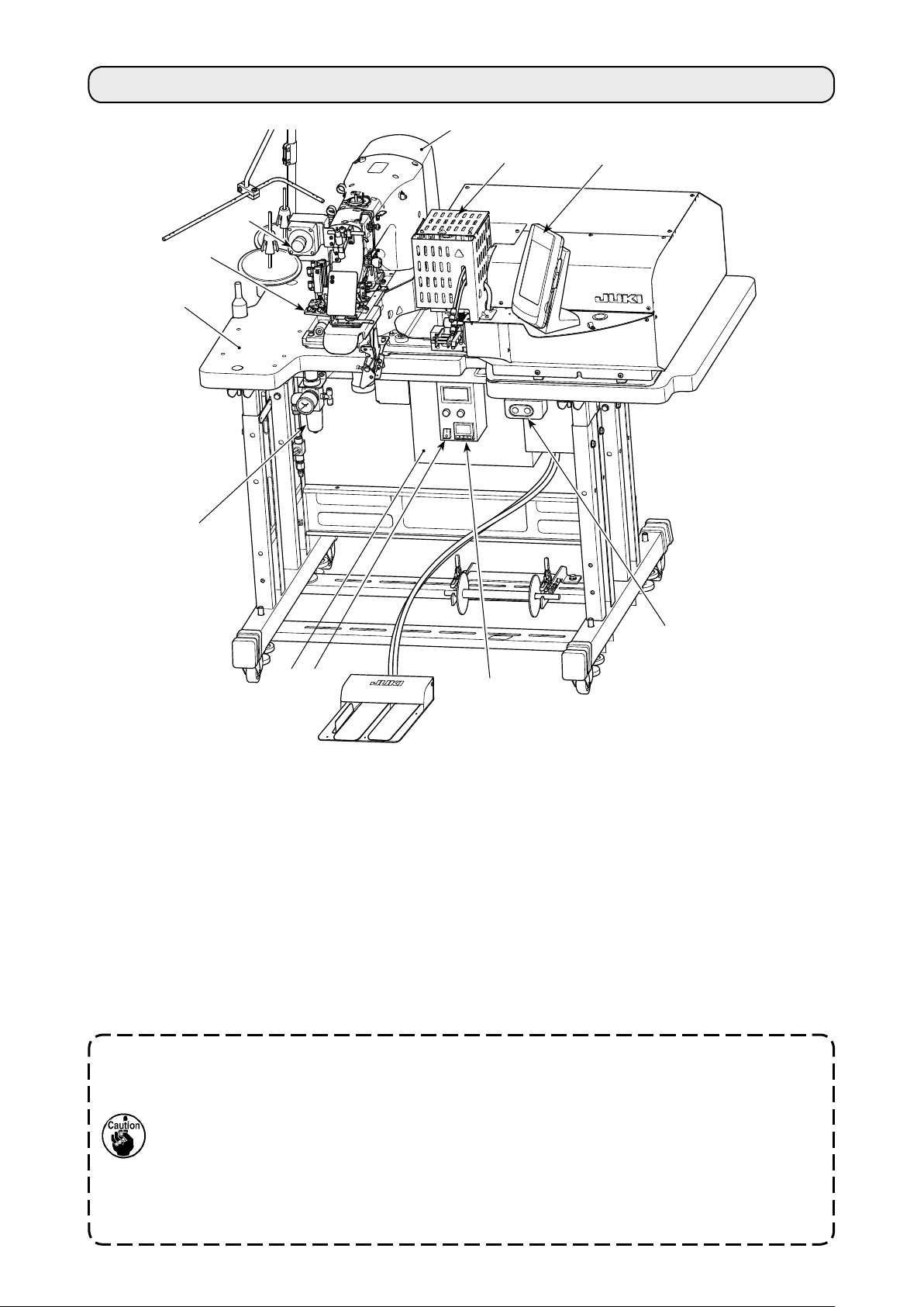
This machine consists of the following eleven sections
I
.
The machine is able to automatically sew desired shoelace loop only by operating the start switch after
having placed a material (garment body) at the predetermined position on the machine.
When you press emergency stop switch H, the power to the devices are turned OFF to stop them.
A Mechanical section of the main body structure (table stand, table, covers, start switch, etc.)
B Loop feeder unit (loop feeding device, loop drawing device, heat cutter)
C Loop tension releasing unit
D Pneumatic control equipment section (pneumatic equipment, pneumatic piping, etc.)
E Sewing machine section
Control device
F
G Operation panel H Emergency stop switch
I Heat cutter controller
Power switch
J
K Heat cutter controller power switch
Heat the heat cutter to enable its operation, it is necessary to turn ON the heat cutter controller power switch K.
The power switch of the heat cutter is independent from the sewing machine power switch. It
is therefore necessary to turn OFF not only the heat cutter controller power switch but also
sewing machine power switch J when the sewing machine is not used.
In addition, it should be remembered that the heat cutter requires a certain period of time until
it becomes sufciently hot for use after turning ON the power switch. To ensure that the heat
cutter is operable whenever necessary, be sure to turn ON heat cutter controller power switch
K in prior and check that the heat cutter temperature is sufciently high. (For the adjustment
of temperature, refer to "I.5-8. Adjusting the heat cutter temperature" p.20.)
– 2 –
Page 8
2. Specications
2-1. Mechanical specications
1 Sewing machine in use LK-1962/AB H (exclusive intermediate machine head AB-1360 based on LK-1900A SS)
Max. 2,500 sti/min (adjustable range: 400 to 2,500 sti/min)
2 Sewing speed
3 Loop shape
4 Shoelace loop width 6 to 12 mm
The stitching pitch has to be set at 3.2 mm or less. (Stitching pitch is input in increments
of 100 sti/min.)
5 Standard sewing
pattern
Lift of the work clamp
6
foot of sewing machine
7 Needle bar stroke 45.7 mm (for 1903A)
8 Needle ORGAN needle DP×17 #18 (Standard)
9 Hook in use Semi-rotary standard hook (x1.0)
10 Thread Filament #40
11 Safety feature
12 Lubrication oil JUKI New Defrix Oil No.2
13 Air pressure used 0.5 MPa
14 Air consumption 10 dm³ (ANR)/min or less
15 Dimensions W: 1,200 mm L: 850 mm H: 1,210 mm
16 Weight 205.5 kg
17 Noise Declaration
* Linear bartacking (exclusive pattern for AB-1360)
Pattern number selection method (from among 16-stitch) is adopted. The widthwise
pattern size is input on the operation panel. The lengthwise pattern size is restricted
to the 0 mm, and the widthwise one is restricted to the range from 7.6 to 15 mm. (The
lengthwise pattern size is input in increments of 0.1 mm.)
The distance from the top surface of the throat plate to the undersurface of the work
clamp foot is 20 mm.
The machine automatically stops in the case a loop clamping fault or thread breakage is
detected.
- Equivalent continuous emission sound pressure level (LpA) at the workstation :
A-weighted value of 82.0 dB; (Includes KpA = 2.5 dB); according to ISO 10821 - C.6.3
-ISO 112112 04 GR2 at 2,500 sti/min for the sewing cycle, 5.5s ON. (Pattern: No.4, 21
Stitches, Max Speed)
- Sound power level (LWA) ;
A-weighted value of 85.0 dB; (Includes KWA = 2.5 dB); according to ISO 10821 - C.6.3
-ISO 3744 GR2 at 2,500 sti/min for the sewing cycle, 5.5s ON. (Pattern: No.4, 21
Stitches, Max Speed)
18 Laser marking Class 2 laser product
Maximum output: 1.0 mW
Wave length: 650 nm
Safety standard
JIS C 6802:2005
IEC60825-1+A2:2007
– 3 –
Page 9
2-2. Electrical specications
1 Number of patterns that
can be stored in memory
2 Number of cycles that
can be stored in memory
3 Input power source Single-phase 220 – 240 VAC, 50/60Hz
4 Power consumption
99 patterns can be set.
Number of programs: 20
For each program, as many as 30 loops can be set.
Supply voltage uctuation: Rated voltage ± 10 % or less
Single-phase, 220 V type: 420 VA (instantaneous maximum power consumption: 655 VA)
* Average power when the machine sews 2,100 loops in eight hours.
2-3. Shoelace specications
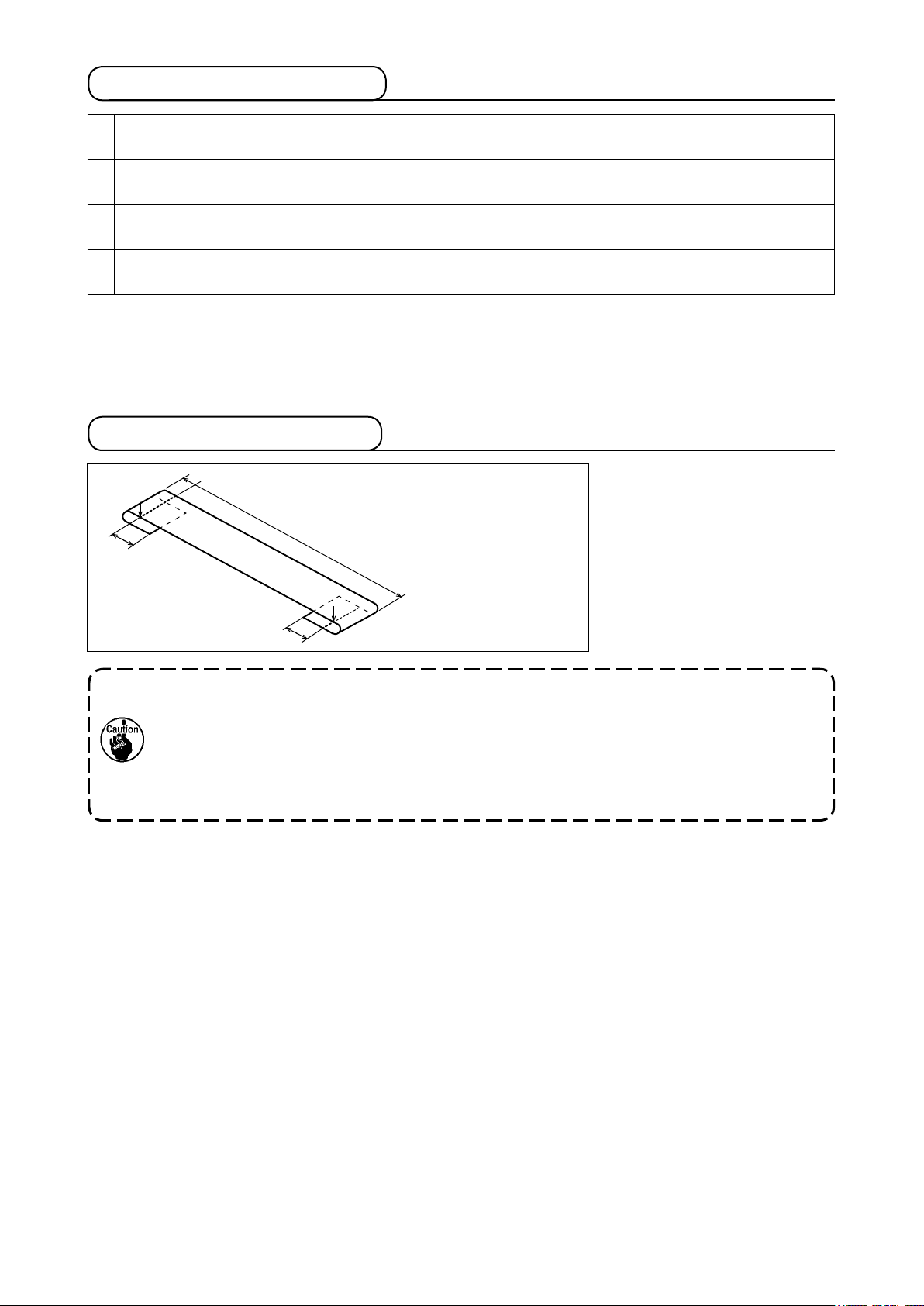
E
F
B
A = 4 mm *(0 to 15)
B = 12 to 17
E = 3 mm (0 to 5)
F = 4 mm (0 to 5)
A
The dimensions of the shoelace loop sewing shape displayed on the operation panel are
only for reference. The dimensions vary according to the shoelace loop material. Be sure to
adjust the settings of shoelace loop dimensions so that your desired nished dimensions
are achieved.
* Numerical values shown in parentheses are set values. They are not the nished dimen-
sions.
– 4 –
Page 10
3. Installation
3-1. Removing the packing materials
CAUTION
:
1. If you lift the machine, do not hold any of the devices or the mechanical section of the
sewing machine but hold the table.
2. When you move the machine, the machine head xation bolt must be attached to the
machine. Be sure to carefully keep the machine head xation bolt.
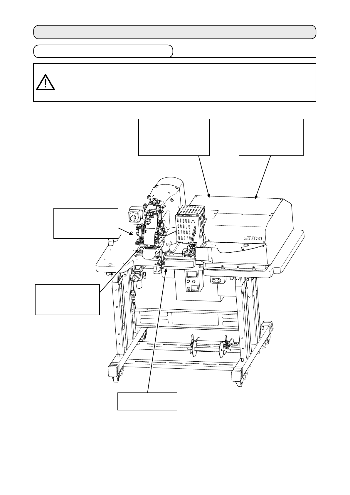
Remove the upper section
cover. Remove the string
and packing material
which are used to x the
loop drawing unit.
Remove the string and
packing material which
are used to x the loop
tension releasing unit.
Remove the upper
section cover. Remove
the string and packing
material which are
used to x the XY unit.
Remove the adhesive
tape which is used to
x the garment body
presser.
Remove the machine
head xation bolt.
– 5 –
Page 11
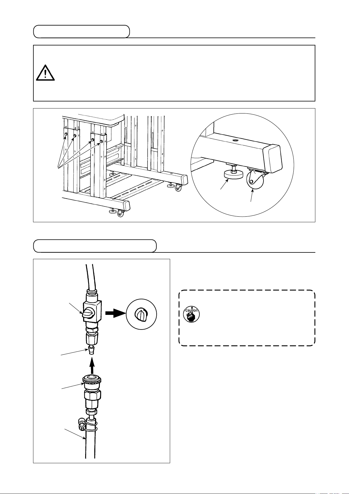
3-2. Fixing the machine
CAUTION
1. In order to protect against accidents causing personal injury or death, move the
machine to a level and stable place and secure it by lowering adjuster bolts ❷ (at four
locations) placed at the side of casters ❶.
2. When adjusting the leg height of the sewing machine, the leg xing bolts ❸ need to be
loosened to move the leg up or down. When the xing bolts have been loosened, there
is a danger for the legs to suddenly drop down. Therefore, be careful when loosening
the bolts.
❸
:
❷
❶
3-3. Connecting the air coupler
❹
❸
❶
Connect air coupler ❶ supplied with the unit as an
accessory to air hose ❷. Then, connect the air
coupler to coupler ❸ on the main body side.
1. After having connected coupler ❶
with air cock ❹ closed, carefully
open air cock ❹ to supply air.
2. Check to be sure that the pressure
gauge of the regulator indicates 0.5
MPa.
❷
– 6 –
Page 12
3-4. Connecting the power plug
CAUTION
In order to protect against accidents caused by a ground fault or dielectric voltage, be
sure to have the adequate power plug mounted by a person who has electrical expertise. It
is also important to connect the power plug to the grounded receptacle.
:
The method to connect the product to the power source differs by the product specications. Be sure to
connect the product to the power source according to the power specications.
① For the single-phase, 220 - 240 V type product
Connect the sky-blue/brown wire of the power cord to the supply terminal (220 - 240 VAC) and the
yellow/green one to the earth terminal respectively.
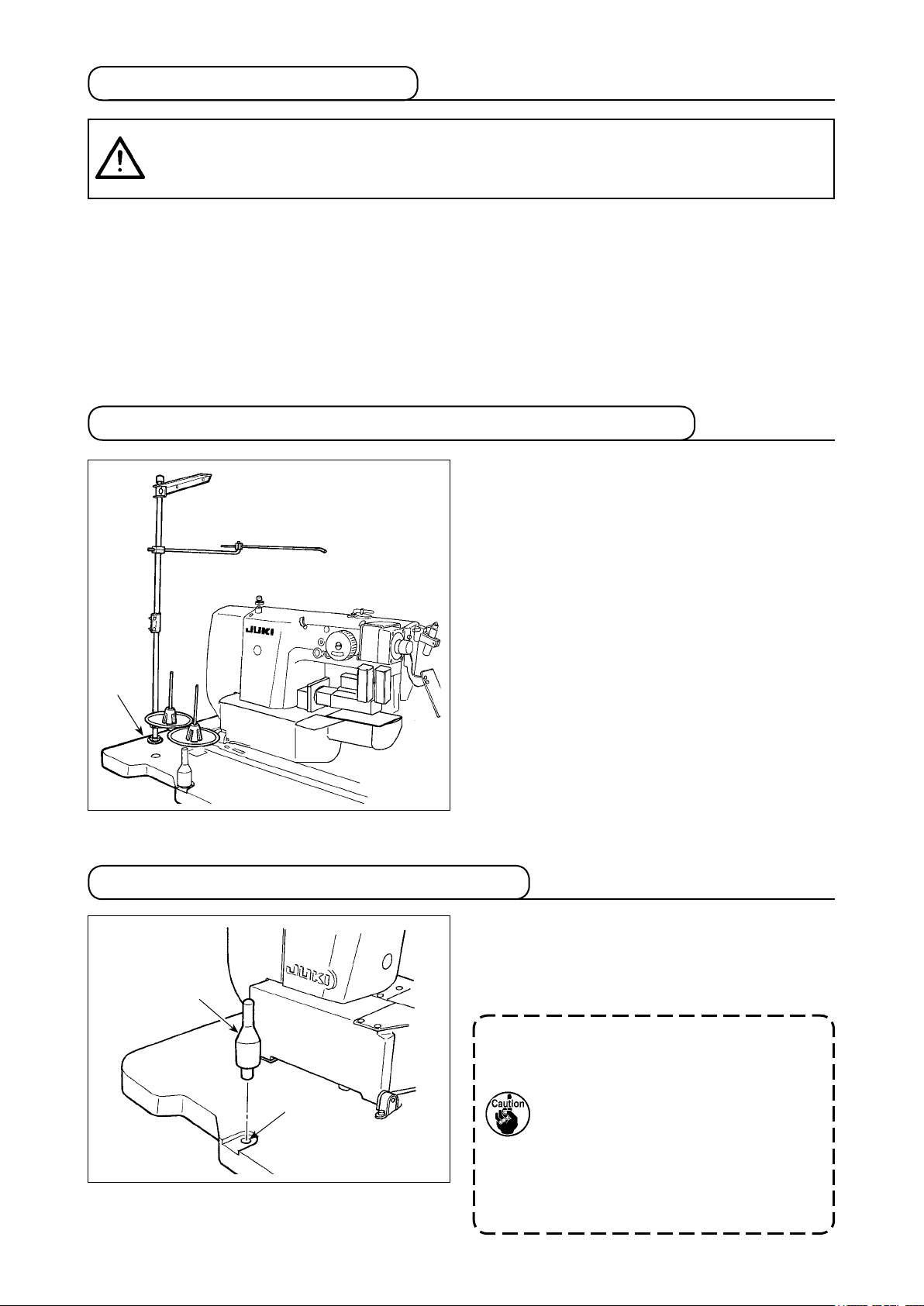
3-5. Assembling the thread stand and installing on the machine
Insert the thread stand in the hole in table ❶ and
x by fastening a washer and a nut placed on the
top and underside of table.
❶
3-6. Installing the machine head support bar
Securely mount machine head support bar includ-
ed in the accessories supplied with the unit.
Drive machine head support bar ❶ in hole ❷ in
❶
❷
the machine table.
When tilting the sewing machine, tilt
the sewing machine slowly so that no
excessive force will be applied to the
head support bar.
And when returning the sewing ma-
chine back to its original position,
be careful not to have your hand get
caught between the base and the sew-
ing machine bed.
– 7 –
Page 13
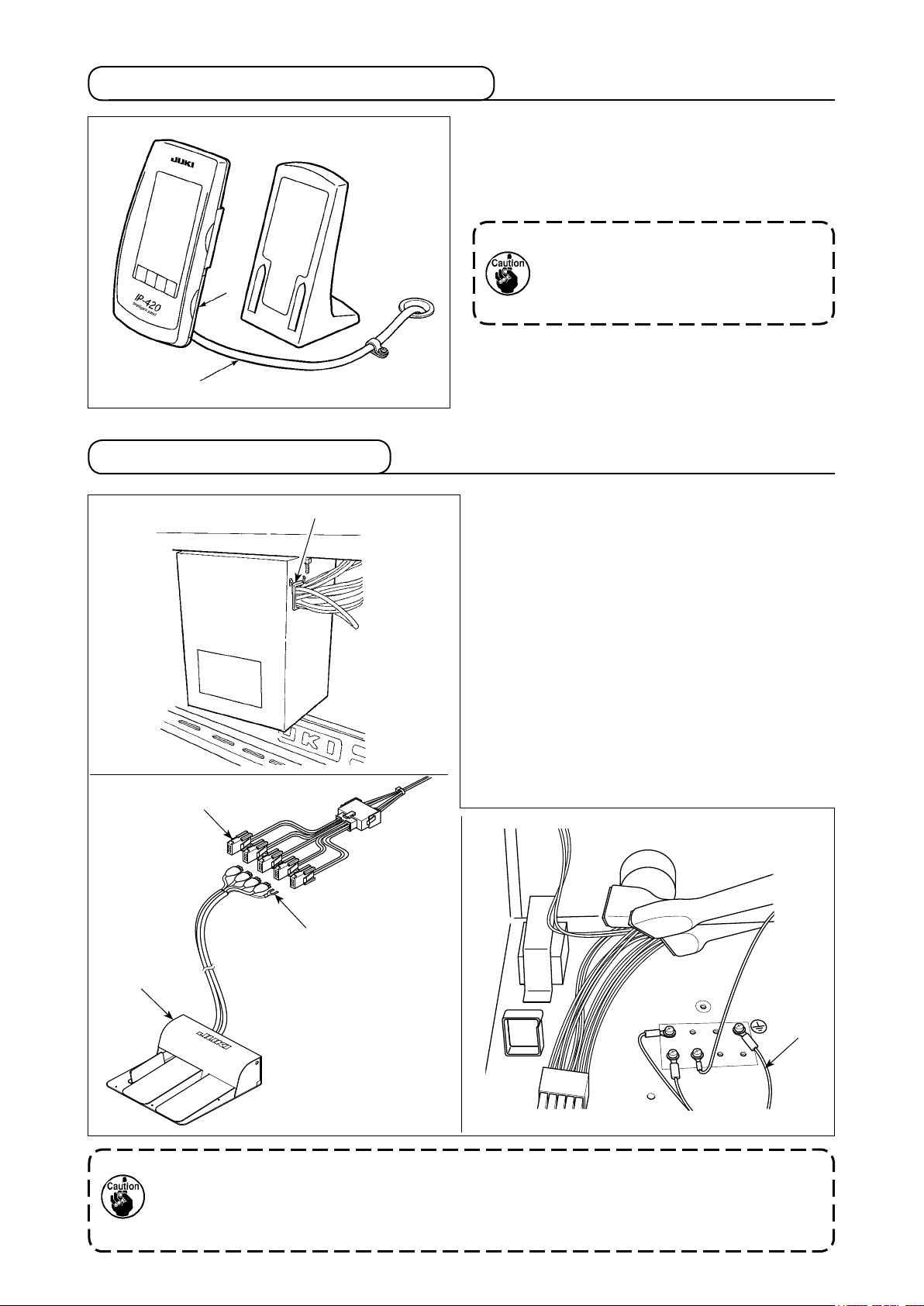
3-7. Installing the operation panel IP-420
❷
❶
3-8. Installing the 3-pedal unit
Open the cover on right side face ❷ section of
the IP-420 and connect the connector of cable ❶
which is secured with adhesive tape on the upper
right face of the table to the IP-420.
To protect the operation panel IP-420
from malfunctioning due to static elec-
tricity, mount the operation panel on the
operation panel base.
❸
❹
❶
1) Remove cord retaining plate (17845009) ❶ which
is attached to the wiring draw-out opening of the
control box.
2) Pass the cable of 3-pedal unit (GPK470010AB)
❷ into the inside of the control box through wiring
draw-out opening.
3) Connect the connectors CN1 and CN2 of 3-pedal
unit ❷ to the connectors CN2 and CN5 of junction
cable (40033875) ❸ in the written order.
4) Fix earth cable❹ of the 3-pedal unit to the inner
bottom of the control box.
5) Attach cord retaining plate ❶ to the wiring draw-
out opening of the control box.
❷
If the cable of 3-pedal unit ❹ is wrongly connected to junction cable ❸, the pedal will fail to
operate though the machine will not fail. It is necessary to connect the cables as indicated.
In addition, do not connect two remaining connectors other than connectors CN1 and CN2
of 3-pedal unit ❷.
– 8 –
❹
Page 14

3-9. Installing the additional marking light (optional)
Insert exclusive junction cable ❶ into connector
CN85 ❷ of the junction board located behind the
❷
❶
main body.
(There are three CN85 connectors including the
one used as standard. You may insert the junction
cable any of the three connectors.)
– 9 –
Page 15
4. Preparation of the sewing machine
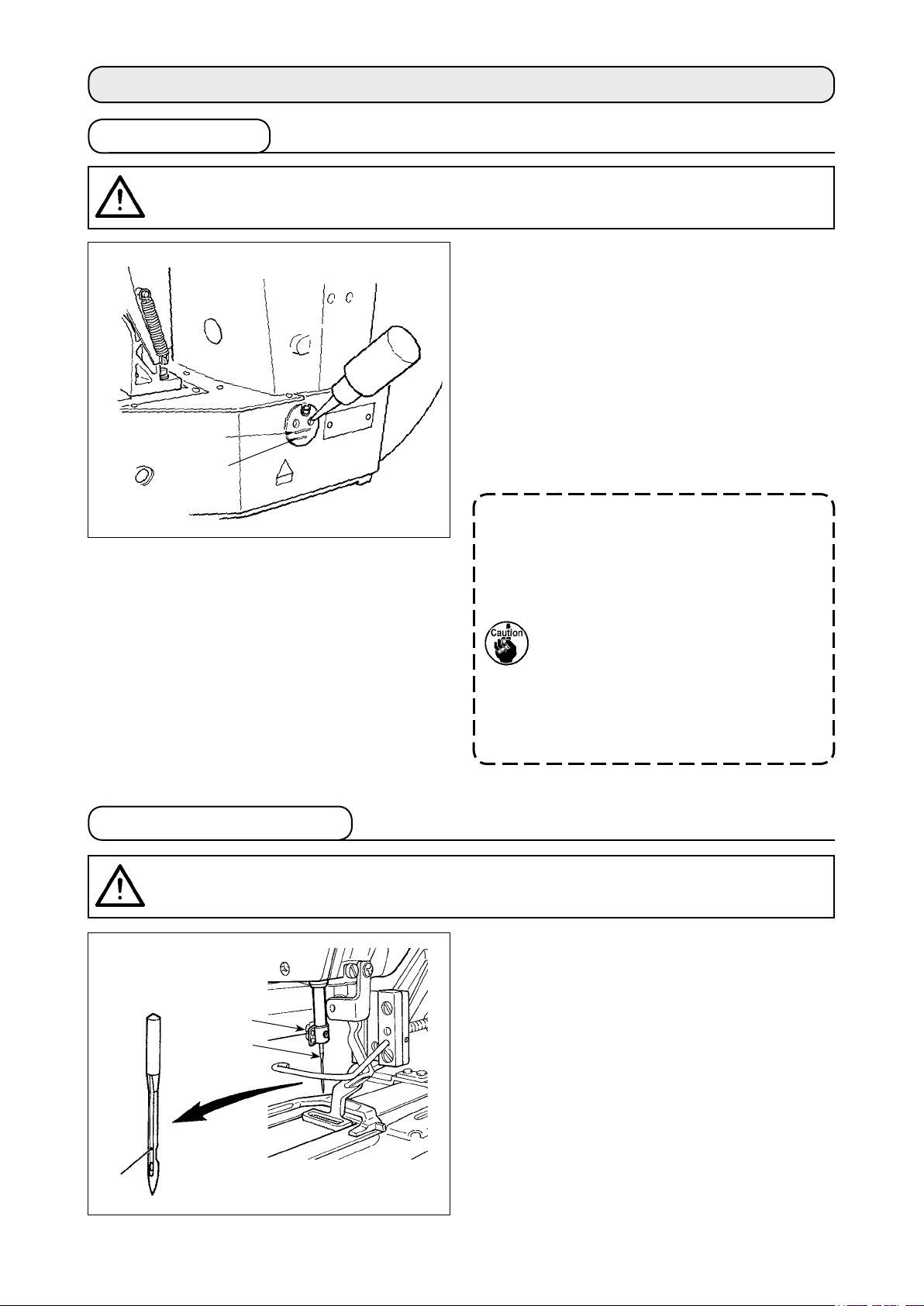
4-1. Lubrication
CAUTION
Turn OFF the power before starting the work so as to prevent accidents caused by abrupt
start of the sewing machine.
:
Check that the place between lower line B and up-
per line A is lled with oil. Fill there with oil using
the oiler supplied with the machine as accessories
when oil is short.
* The oil tank which is lled with oil is only for lu-
bricating to the hook portion.
It is possible to reduce the oil amount when the
sewing speed used is low and the oil amount in
A
B
the hook portion is excessive. (Refer to
Amount of oil supplied to the hook" p.112
1. Do not lubricate to the places other
than the oil tank and the hook of Cau-
tion 2 below. Trouble of components
will be caused.
2. When using the sewing machine for
the rst time or after an extended
period of disuse, use the machine
after lubricating a small amount of oil
to the hook portion. (Refer to "III.1-3.
Adjusting the needle-to-shuttle rela-
tion" p.109.)
"III.1-10.
.)
4-2. Attaching the needle
CAUTION
Turn OFF the power before starting the work so as to prevent accidents caused by abrupt
start of the sewing machine.
❸
:
❶
❷
Loosen setscrew ❶ and hold needle ❷ with the
long groove facing ❸ toward you. Then fully insert
it into the hole in the needle bar, and tighten set-
screw ❶.
– 10 –
Page 16

4-3. Threading the machine head
CAUTION
Turn OFF the power before starting the work so as to prevent accidents caused by abrupt
start of the sewing machine.
:
❶
❷
Draw the thread after having threaded the needle so that approximately 4 cm thread trails from the nee-
dle eyelet.
1. When you use silicon oil, pass the thread through silicon-thread thread guide ❶. (Sili-
con-thread thread guide is an optional part.)
2. Wind thread on needle clamp thread guide ❷ to form an S-shape as shown in the gure
given above in order to ensure stable sewing and thread trimming.
4-4. Installing and removing the bobbin case
CAUTION
Turn OFF the power before starting the work so as to prevent accidents caused by abrupt
start of the sewing machine.
:
1) Open hook cover ❶.
❸
2) Raise latch ❸ of bobbin case ❷, and remove
the bobbin case.
3) When installing the bobbin case, fully insert it into
the hook shaft, and close the latch.
❷
❶
If it is not fully inserted, bobbin case ❷
may slip off during sewing.
– 11 –
Page 17
4-5. Installing the bobbin
CAUTION
Turn OFF the power before starting the work so as to prevent accidents caused by abrupt
start of the sewing machine.
:
2.5 cm
❹
❸
❶
❷
4-6. Adjusting the thread tension
❺
1) Set the bobbin ❶ into bobbin case ❷ in the
direction shown in the gure.
2) Pass the thread through thread slit ❸ of bobbin
case ❷, and pull the thread as it is. By so doing,
the thread will pass under the tension spring and
be pulled out from thread hole ❹.
3) Pass the thread through thread hole ❺ of the
horn section, and pull out the thread by 2.5 cm
from the thread hole.
If the bobbin is installed in the bobbin
case orienting the reverse direction, the
bobbin thread pulling out will result in
an inconsistent state.
❶
Long
Short
Adjusting the needle thread tension
❷
If thread tension controller No. 1 ❶ is turned
clockwise, the length of remaining thread on the
needle after thread trimming will be shorter. If it is
turned counterclockwise, the length will be longer.
Shorten the length to an extent that the thread is
not slipped off.
(The standard length of thread remaining on the
needle is approximately 4 cm.)
The needle thread tension is adjustable on the
operation panel. The bobbin thread tension is ad-
justable by means of ❷.
The needle thread tension to be applied to the
bartacking sections can be set by means of thread
tension setting button A on the operation panel.
A
– 12 –
Page 18
4-7. Adjusting the thread take-up spring
The standard stroke of thread take-up spring ❶ is
10 to 11 mm, and the pressure at the start is 0.5
to 0.6 N.
❶
1) Adjusting the stroke
Loosen setscrew ❷, and turn thread tension asm.
❹
❸.
Turning it clockwise will increase the moving
amount and the thread drawing amount will in-
❸
❷
crease.
2) Adjusting the pressure
To change the pressure of the thread take-up
spring, insert a thin screwdriver into the slot of
thread tension post ❹ while screw ❷ is tightened,
and turn it. Turning it clockwise will increase the
pressure of the thread take-up spring. Turning it
counterclockwise will decrease the pressure.
4-8. Example of the thread tension
When using the sewing machine for the rst time, adjust the thread tension referring to the table below.
Thread Material
Nylon bonded thread #40 Sports shoes material 60 to 65 10 mm [13 mm] 0.5 N
Needle thread
tension setting
Thread take-up spring
moving amount
[Thread drawing amount]
Strength
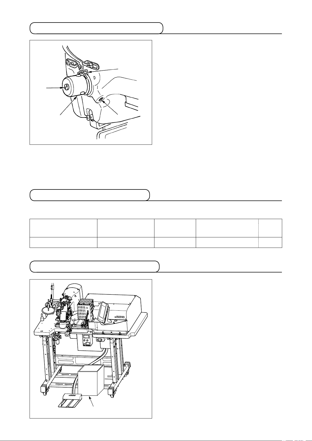
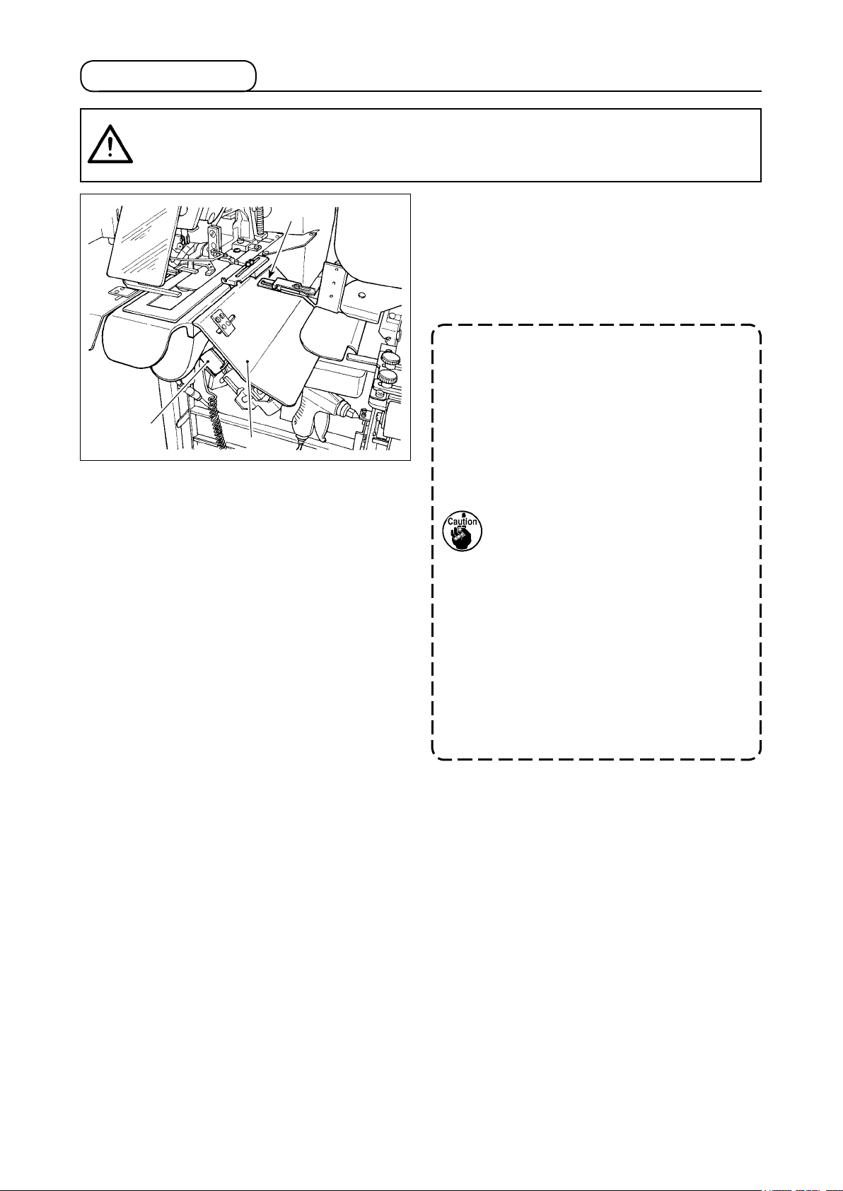
4-9. Installing the ejected loop receiver
The loop feeder unit ejects the rst loop before start-
ing sewing in order the ensure the predetermined
cutting length. Install a large collection box for col-
lecting ejected loops.
Loop collection box
– 13 –
Page 19
5. Operating the sewing machine
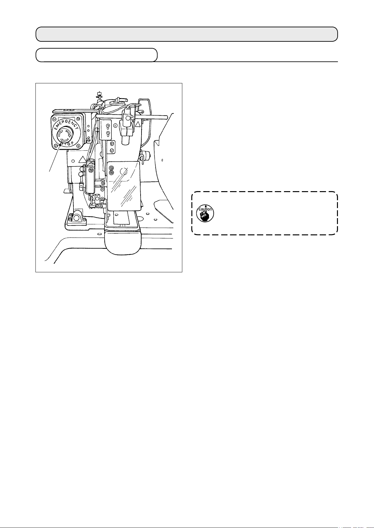
5-1. Emergency stop switch
(1) Method for operating the emergency stop switch
Emergency stop switch ❶ is mounted on the up-
per left section of the sewing machine head.
Emergency stop switch ❶ is turned ON by strong-
ly pressing in the red button. It is turned OFF by
turning it counterclockwise.
If you turn ON emergency stop switch ❶ while the
machine is in operation, the power is turned OFF
to cause the machine to stop operation.
At this time, the loop cutting operation as well as
❶
the loop feeding switch of the heat cutter also
stop.
If you turn OFF emergency stop switch
❶ with the power switch remained ON,
the power is re-turned ON. Take care of
abrupt re-turn ON of the power.
To turn OFF the power for any purpose other than
an emergency stop, operate the power switch.
(2) Precautions with the emergency stop switch
When emergency stop switch ❶ stays ON, the sewing machine cannot be powered up even if you turn
ON/OFF the power switch. The work clamp foot of the sewing machine may depress the loop clamp or
the loop loosening rod according to the operation timing of emergency stop switch ❶. If this phenome-
non occurs, turn OFF the power to the sewing machine and manually lift the work clamp foot of the sew-
ing machine to move it so as to avoid interference. Then, re-turn ON the power to the sewing machine.
– 14 –
Page 20
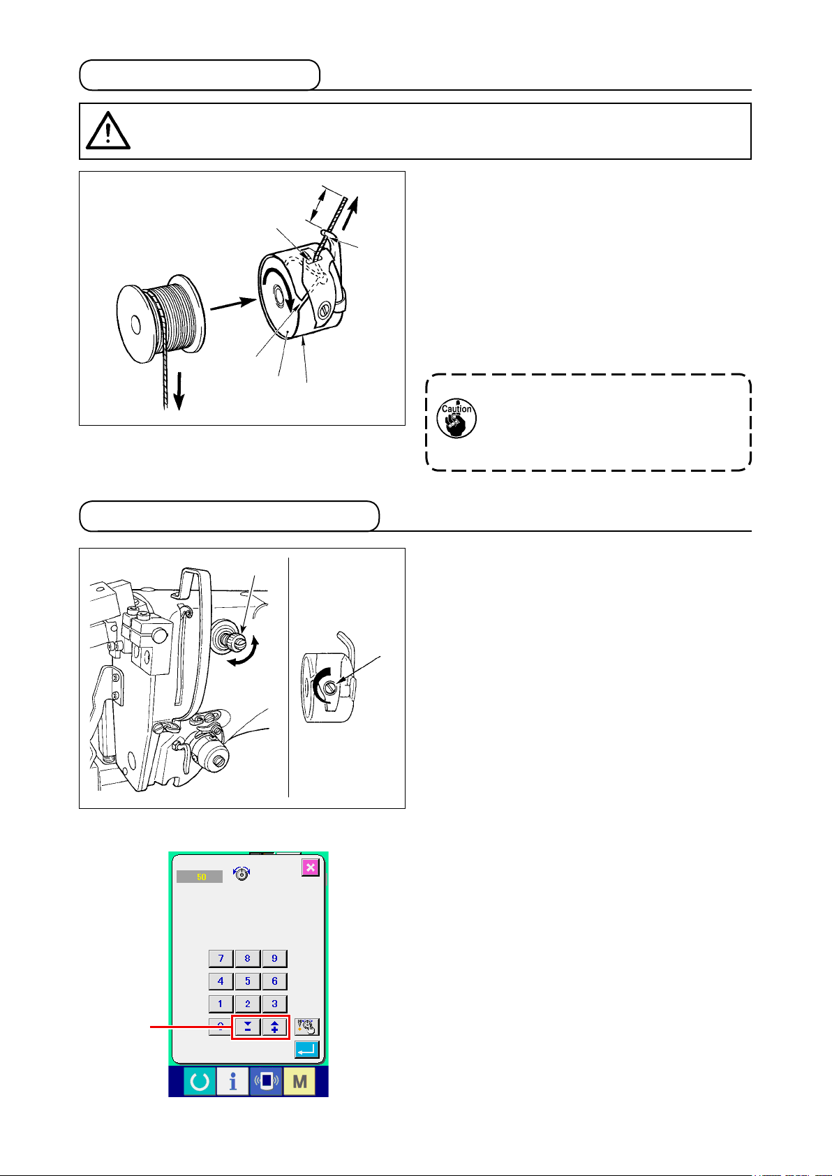
5-2. Winding a bobbin
(1) To wind a bobbin while the sewing machine is performing sewing
Thread the bobbin winder and wind the bobbin
thread onto the bobbin as illustrated in the gure.
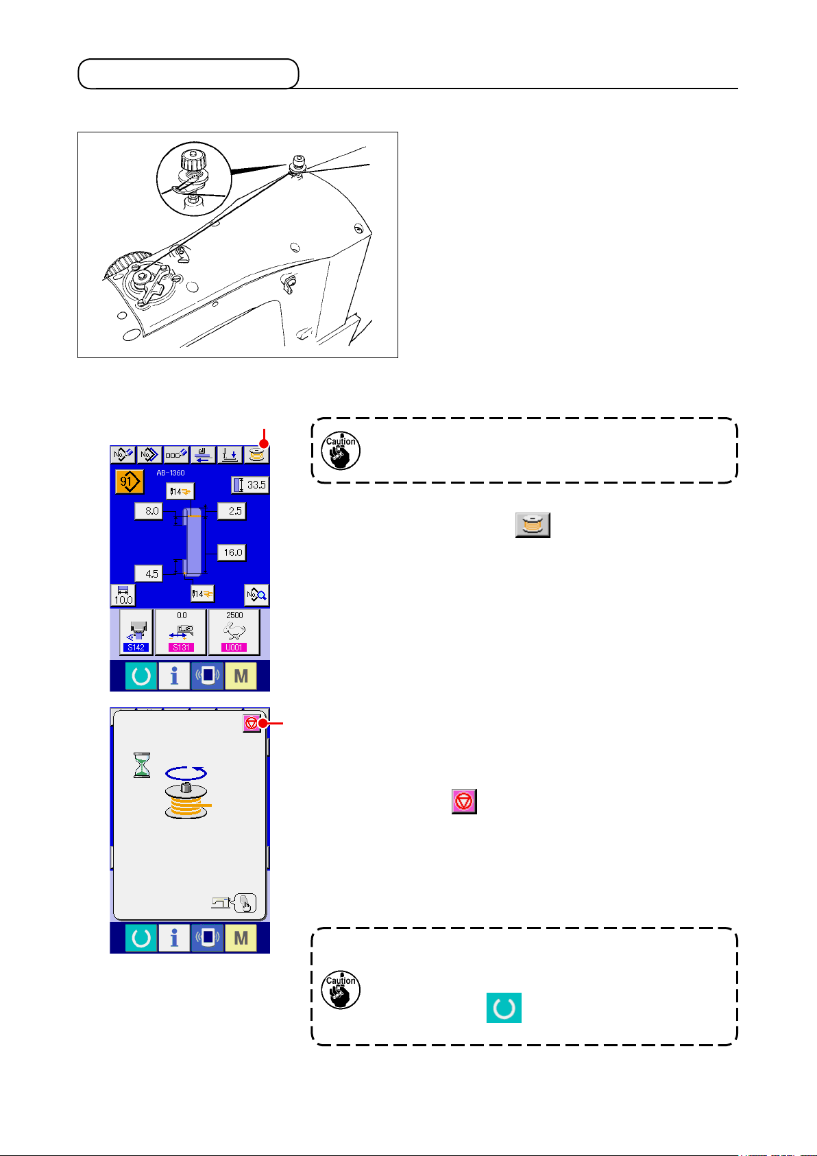
(2) To wind a bobbin independently
A
In the case you only want to carry out bobbin winding
on the sewing machine, unthread the needle and remove
the bobbin from the hook.
① Displaying the bobbin thread winding screen
Press bobbin winding button A on the shoelace loop data
input screen (blue), and the bobbin winding screen appears on
the screen.
② Starting bobbin winding
B
Press the start switch, and the sewing machine rotates to start
bobbin winding.
③ Stopping the sewing machine
Press stop button B, and the sewing machine stops and
returns to the normal mode. If you press the start switch again
during bobbin winding, the sewing machine stops under the bob-
bin winding mode. If you press the start switch again in this state,
the sewing machine re-starts bobbin winding. Use this operating
procedure when you want to wind thread on two or more bobbins.
The bobbin winding will not start immediately after
turning the power ON. To activate the bobbin winding
function, set a pattern number or the like rst, then press
the set ready key to invoke the sewing screen. In
this state, the bobbin winding function is enabled.
– 15 –
Page 21
5-3. Thread clamp device
Trouble of sewing (slip-off of needle thread, stitch skipping, or stain of needle thread) at the time of high-
speed start can be prevented with the thread clamp device.
The thread clamp device will operate when the thread clamp button has been selected , but it will
not operate when the thread clamp button has not been selected .
Changeover of ON/OFF motion is performed with key. When the thread clamp device is in the
OFF state, the sewing machine is automatically set to the soft-start mode.
1. When memory switch is "1" (prohibited), the thread clamp does not work. Fur-
thermore, the thread clamp key will not be displayed.
2. Memory switch, refer to "II.2-26. How to change the memory switch data" p.75.
* Matters that demand special attention when using the needle thread clamp
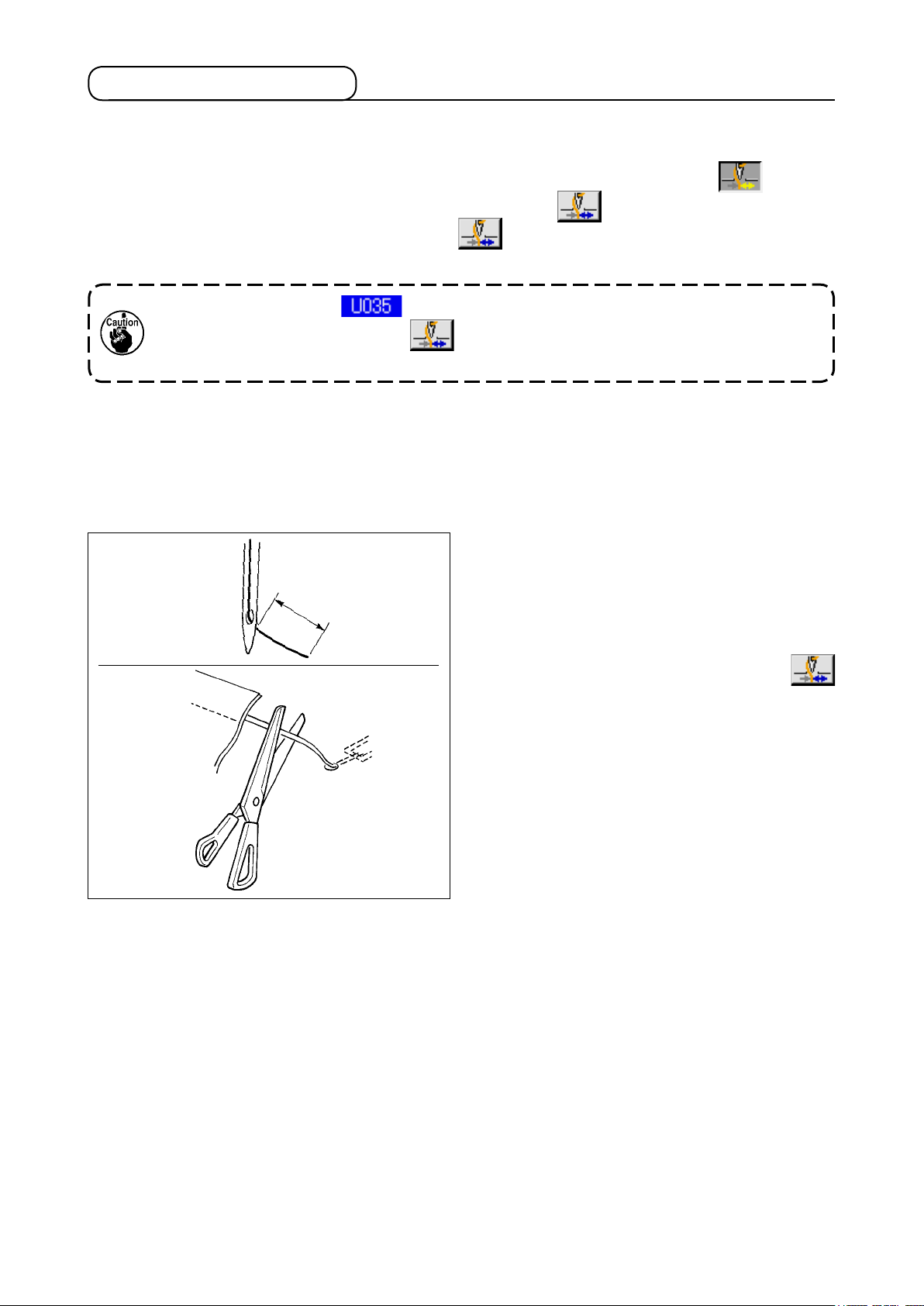
(1) In case of with the needle thread clamp (motion), make shorter the length of needle thread remaining on
the needle at the sewing start for use. When the length of needle thread is lengthened, needle thread
on the wrong side of material is apt to protrude. In addition, when the length is excessively lengthened,
the end of needle thread held by the needle thread clamp may be rolled in the seams.
1)
1) In case of with the needle thread clamp, the
standard of the length of needle thread is 33 to
36 mm.
33 to 36 mm
2) When needle thread is long after replacing thread
or the like or sewing while holding needle thread
3)
by hand, turn OFF the THREAD CLAMP
key.
3) When the needle thread held with the thread
clamp is rolled in the seams, do not draw the
material forcibly and cut the connecting needle
thread with the scissors or the like. The seams
are not damaged since it is the needle thread at
the sewing start.
(2) It is possible to adjust needle thread shorter by making the needle thread clamp work while holding the
stabilized sewing at the start of sewing and the gathering (bird's nest) of needle thread on the wrong
side of material can be lessened. However, for the pattern which the stitch length for neatly rolling in
needle thread is short, needle thread may protrude from the wrong side of material.
In addition, thread waste could accumulate around the hook due to thread trimming when the thread
clamp device is used. Be sure to periodically clean inside the hook cover referring to "II.1-12. Cleaning
inside the hook cover" p.113.
– 16 –
Page 22
5-4. Placing a shoelace loop
❸
❹
❷
❶
Pass the loop through guide ❶, pull up lever ❷ at
the roller section and insert the loop under roller ❸.
When you route the shoelace loop
under the gear, insert it until it appears
from the loop cutting knife.
* When the heat cutter controller power is ON, a
shoelace loop is fed by means of the motor by
pressing loop feeding switch ❹ of the heat cutter
controller is pressed.
When the machine is used under a high
shoelace loop tension, the entire length
of the fed shoelace loop is shortened.
In such a case, malfunctions such that
the shoelace of the predetermined
length cannot be sewn or that the shoe-
lace loop cut edge is not
straight can occur. To prevent those malfunctions,
it is necessary to adjust
the shoelace loop tension
adequately.
5-5. Adjusting the shoelace loop tension
When you have changed the shoelace loop, you need to re-adjust
A
the shoelace loop tension without exceptions.
Press the shoelace loop tension button A on the sewing
screen.
The more the shoelace loop tension is adjusted in a negative direction, the less the shoelace loop tension becomes. (The shoelace loop tension can be set and stored in memory on a sewing-pattern by sewing-pattern basis.)
As a guide, adjust the shoelace loop tension so that the entire
length of the shoelace loop fed from the shoelace loop feeding
section and clamped at the loop clamping section is shorter than
the entire shoelace loop length displayed when selecting a sewing pattern by approximately 1 mm.
To change the shoelace loop length after the aforementioned
adjustment, nely adjust the feed length so that the entire loop
length as shown in the relevant sewing pattern is achieved, refer-
ring to in
p.72
.
If the sewing machine is operated under a high shoelace loop tension, the entire length
of the shoelace loop fed becomes shorter than required. In this case, problems such that
the shoelace loop cannot be sewing at the predetermined length or that the cut end of the
shoelace loop is not straight can occur. To prevent such problems, adjust the shoelace loop
tension adequately.
– 17 –
Page 23
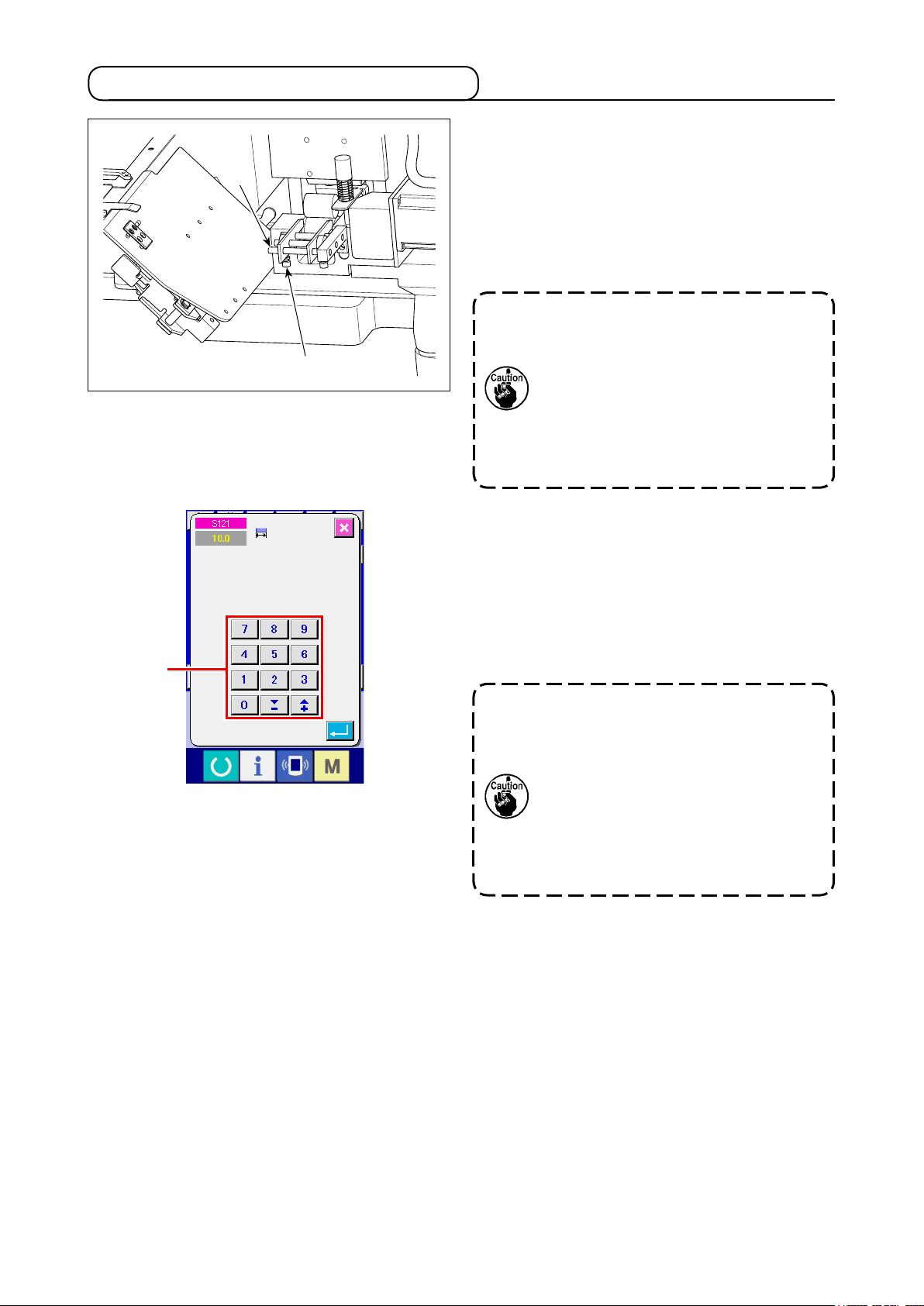
5-6. Method for changing the loop width
❶
❷
A
1) To change the loop width, loosen setscrew ❷ of
left-side shoelace loop guide ❶ and adjust the
guide width so that it matches the shoelace loop
width. Lightly pressing guide ❶ against shoelace
loop, adjust guide ❶ to allow the shoelace loop
smoothly pass through the guide with no lateral
play.
The right-side shoelace loop guide is
used as an across-the-width reference.
So, it is not necessary to adjust it every
time the loop width is changed. How-
ever, adjust the guide position in the
similar matter as described above if the
lateral position of shoelace loop does
not align with the reference.
2) Enter a value of shoelace loop width into shoe-
lace loop width setting section A on the opera-
tion panel screen. At the same time, change the
dimensions of a seam for attaching a shoelace
loop. Refer to "II.2-5. How to change the shoe-
lace loop length" p.32 for the method for
changing the seam dimensions.
If the bartacking width of which is ex-
tremely wider than the shoelace loop
width setting specified through the
operation panel is sewn, the garment
body presser and the loop clamp can
interfere with each other (error No.
M596). If the alarm is given, change the
bartacking width setting to decrease the
bartacking width.
– 18 –
Page 24
5-7. Start switch
CAUTION
When you press the start switch, the garment body presser comes down. At the same
time, the loop clamp moves toward the sewing machine at a high speed. Take added care
to keep your hands away from the loop clamp during work.
:
Once you have completed preparation for sewing,
❷
you can bring the sewing machine into operation
by pressing start switch ❶.
When the loop clamp ❷ has clamped the shoe-
lace loop, operation of the start switch ❶ will be
accepted.
1. Operate the sewing machine taking
care not to allow your hands move
above safety cover ❸ since the
hands can interfere with the loop
❶
❸
2. If you do not keep the start switch
3. You may also press the start switch
clamp.
held pressed for a sufciently long
time, sewing will be interrupted. Be
sure to keep the start switch fully
held pressed.
while the loop clamp clamps the
shoelace loop and travels to the
standby position after the comple-
tion of sewing. In that case, the loop
clamp will not stop at the standby
position but will move directly to
the sewing position to start the next
sewing. Be sure to exercise added
care during this procedure.
– 19 –
Page 25
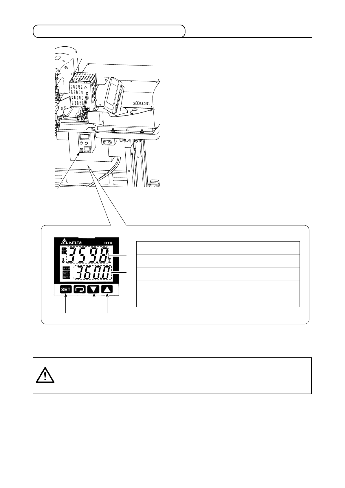
5-8. Adjusting the heat cutter temperature
Heat cutter
Heat cutter controller
It is necessary to adjust the heat cutter tempera-
ture so that it can cut the shoelace loop to be
sewn. (Standard temperature: 360 °C)
Gradually raise the heat cutter temperature while
carrying out trial stitching the shoelace loop to be
sewing until the heat cutter is hot enough to cut
the shoelace loop and weld the cut end without
fail. If the temperature is raised excessively high,
the loop cut end will melt and cut thread waste will
be likely to be produced. In such a case, lower the
heat cutter temperature.
Preset temperature increases.
❶
❹
❸
❷❺ ❶
Preset temperature decreases.
❷
Preset temperature is displayed.
❸
Actual temperature of the cutter section is displayed.
❹
Preset temperature is conrmed.
❺
Adjustment of temperature is carried out on the heat cutter controller panel.
Set the temperature with buttons ❶ and ❷ and conrm the setting with button ❺.
CAUTION
When the temperature indication is displayed on the heat cutter controller panel, the
heater built in the heat cutter is in the heated state.
The temperature of the heat cutter is very high. Be sure to keep your body from the heat
cutter so as to prevent a burn.
:
– 20 –
Page 26
II. OPERATION (OPERATION PANEL)
1. Introduction
1) Type of sewing data handled by the IP-420
Pattern name Description
Vector format data File that extension is “.VDT”
Read from media. Max. 999 patterns can be used.
Sewing data File that extension is “.EPD”
Read from media. Max. 999 patterns can be used.
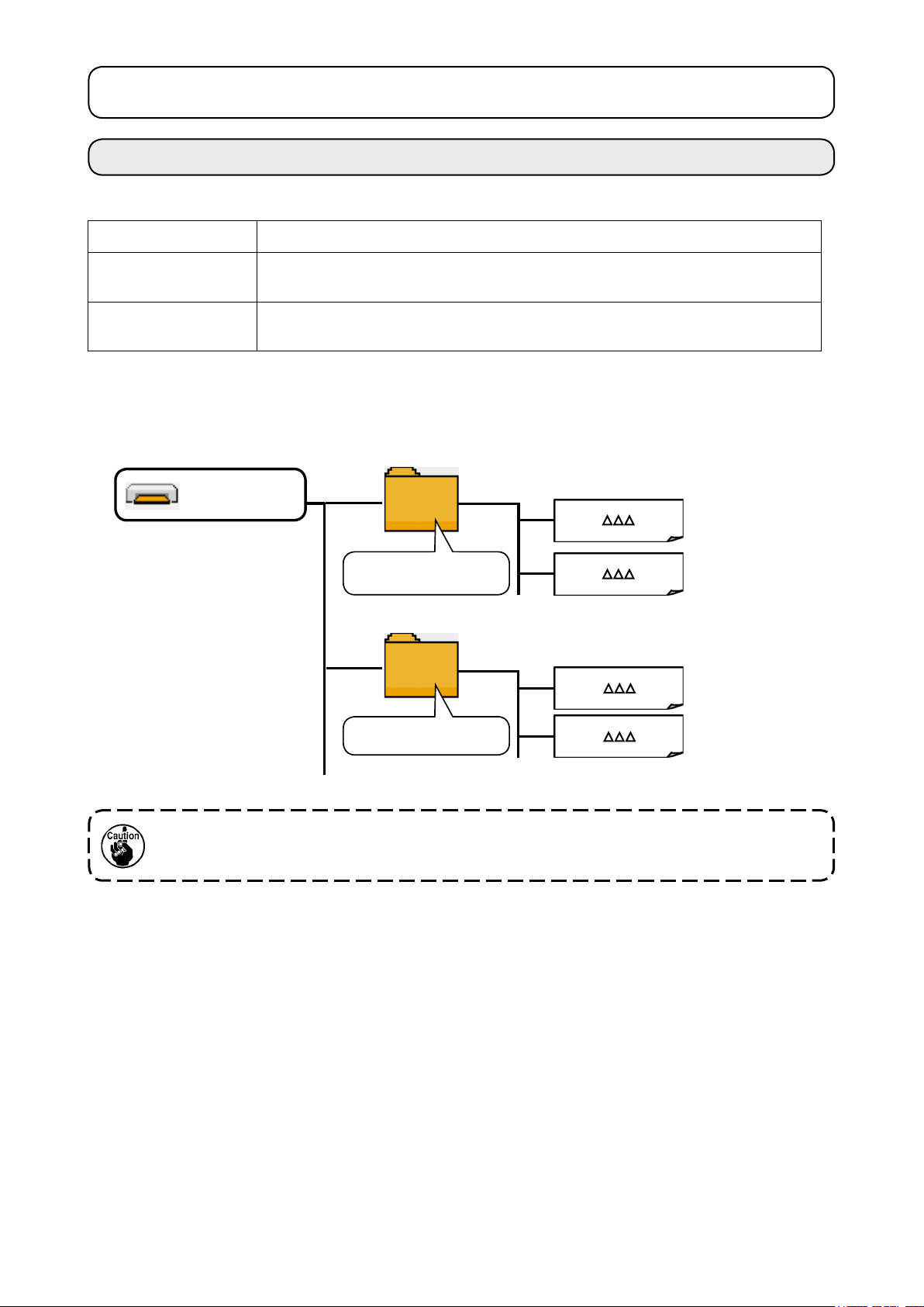
2) Folder structure of the media
Store each le in the directories below of the media.
Media drive
VD ATA
Store vector format
data.
AB-1351
Store sewing data.
VD00 .VDT
VD00 .VDT
AB00 .EPD
AB00 .EPD
Vector format data:
Store in /VDATA.
Sewing data:
Store in /AB-1351.
1. Data that are not stored in the directories above cannot be read. So, be careful.
2. Be aware that the AB-1360 is not able to read the data of the AB-1351 (for belt-loop attaching).
– 21 –
Page 27
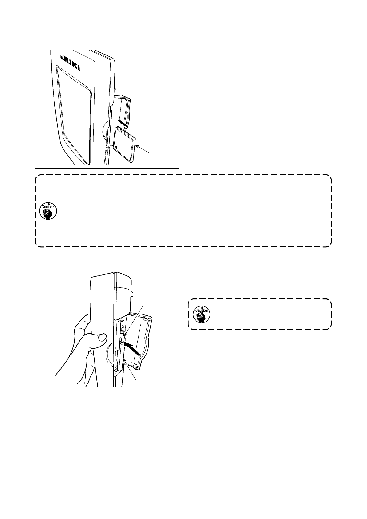
3) CompactFlash (TM)
Inserting the CompactFlash (TM)
■
1) Turn the label side of the CompactFlash (TM)
to this side (place the notch of the edge to the
rear.) and insert the media that has a small
hole to the rear.
2) After completion of setting of the media, close
the cover. By closing the cover, it is possible
to access. If the media and the cover come in
contact with each other and the cover is not
closed, check the following matters.
• Check that the media is securely pressed
until it goes no further.
Media
• Check that the inserting direction of the media
is proper.
1. When the inserting direction of the media is wrong, panel or media may be damaged.
2. Do not insert any item other than the CompactFlash (TM).
3. The media slot in the IP-420 accommodates to the CompactFlash (TM) of 2GB or less.
4. The media slot in the IP-420 supports the FAT16 which is the format of the CompactFlash (TM). FAT32 is not supported.
5. Be sure to use the CompactFlash (TM) which is formatted with IP-420. For the formatting procedure of the CompactFlash (TM), see "II-2-30. Performing formatting of the
media" p.86.
Removing the CompactFlash (TM)
■
❷
❶
1) Hold the panel by hand, open the cover, and
press the media removing lever ❶. The media
is eject.
❷
When the lever ❶ is strongly pressed,
the media ❷ may be broken by protruding and falling.
2) When the media ❷ is drawn out as it is, removing is completed.
– 22 –
Page 28
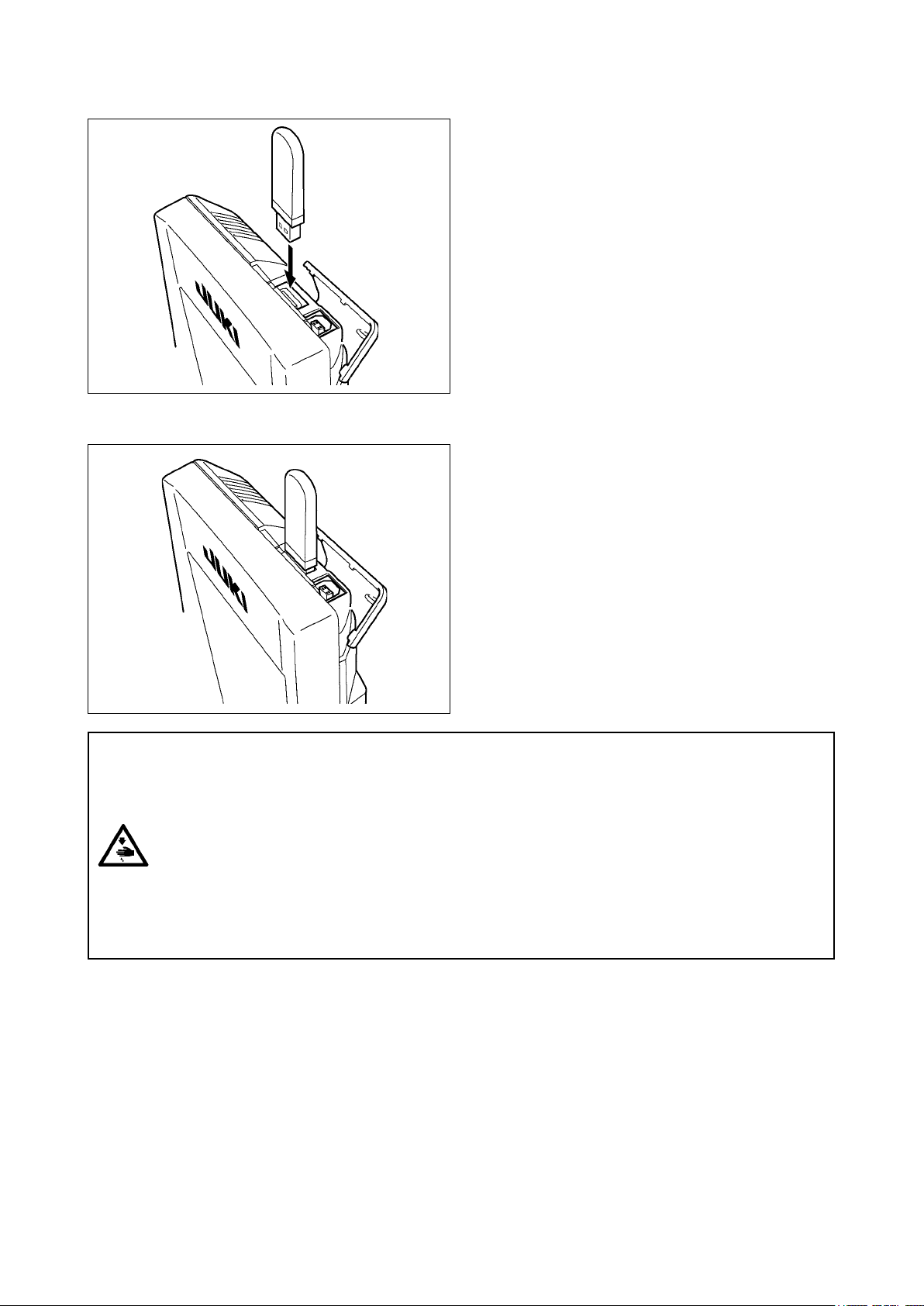
5) USB port
Inserting a device into the USB port
■
Disconnecting a device from the USB port
■
Slide the top cover and insert the USB device into
the USB port. Then, copy data to be used from the
USB device onto the main body.
After completion of copying the data, remove the
USB device.
Remove the USB device. Put the cover back in
place.
Cautions when using the media
• Do not wet or touch it with wet hands. Fire or electric shock will be caused.
• Do not bend, or apply strong force or shock to it.
• Never perform disassembling or remodeling of it.
• Do not put the metal to the contact part of it. Data may be disappeared.
• Avoid storing or using it in the places below.
Place of high temperature or humidity
Place of dew condensation
Place with much dust
Place where static electricity or electrical noise is likely to occur
– 23 –
Page 29

Precautions to be taken when handling USB devices
①
• Do not leave the USB device or USB cable connected to the USB port while the sewing machine is
in operation. The machine vibration can damage the port section resulting in loss of data stored on
the USB device or breakage of the USB device or sewing machine.
• Do not insert/remove a USB device during reading/writing a program or sewing data.
It may cause data breakage or malfunction.
• When the storage space of a USB device is partitioned, only one partition is accessible.
• Some type of the USB device may not be properly recognized by this sewing machine.
• JUKI does not compensate for loss of data stored on the USB device caused by using it with this
sewing machine.
• When the panel displays the communication screen or pattern data list, the USB drive is not recog-
nized even if you insert a medium into the slot.
• For USB devices and media such as CF(TM) cards, only one device/medium should be basically
connected/inserted to/into the sewing machine. When two or more devices/media are connected/
inserted, the machine will only recognize one of them. Refer to the USB specications.
• Insert the USB connector into the USB terminal on the IP panel until it will go no further.
• Do not turn the power OFF while the data on the USB ash drive is being accessed.
USB specications
②
• Conform to USB 1.1 standard
• Applicable devices *1 ������Storage devices such as USB memory, USB hub, FDD and card
reader
• Not-applicable devices ����� CD drive, DVD drive, MO drive, tape drive, etc.
• Format supported ��������FD (oppy disk) FAT 12
Others (USB memory, etc.), FAT 12, FAT 16, FAT 32
• Applicable medium size ����FD (oppy disk) 1.44MB, 720kB
Others (USB memory, etc.), 4.1MB ~ (2TB)
• Recognition of drives ������For external devices such as a USB device, the device which is
recognized rst is accessed. However, when a medium is connected
to the built-in media slot, the access to that medium will be given the
highest priority. (Example: If a medium is inserted into the media slot
even when the USB memory has already been connected to the USB
port, the medium will be accessed.)
• Restriction on connection ��� Max. 10 devices (When the number of storage devices connected to
the sewing machine has exceeded the maximum number, the 11th
storage device and beyond will not be recognized unless they are
once disconnected and re-connected. )
• Consumption current ������ The rated consumption current of the applicable USB devices is 500
mA at the maximum.
*1: JUKI does not guarantee operation of all applicable devices. Some device may not operate due to
a compatibility problem.
– 24 –
Page 30
2. Method for using the operation panel
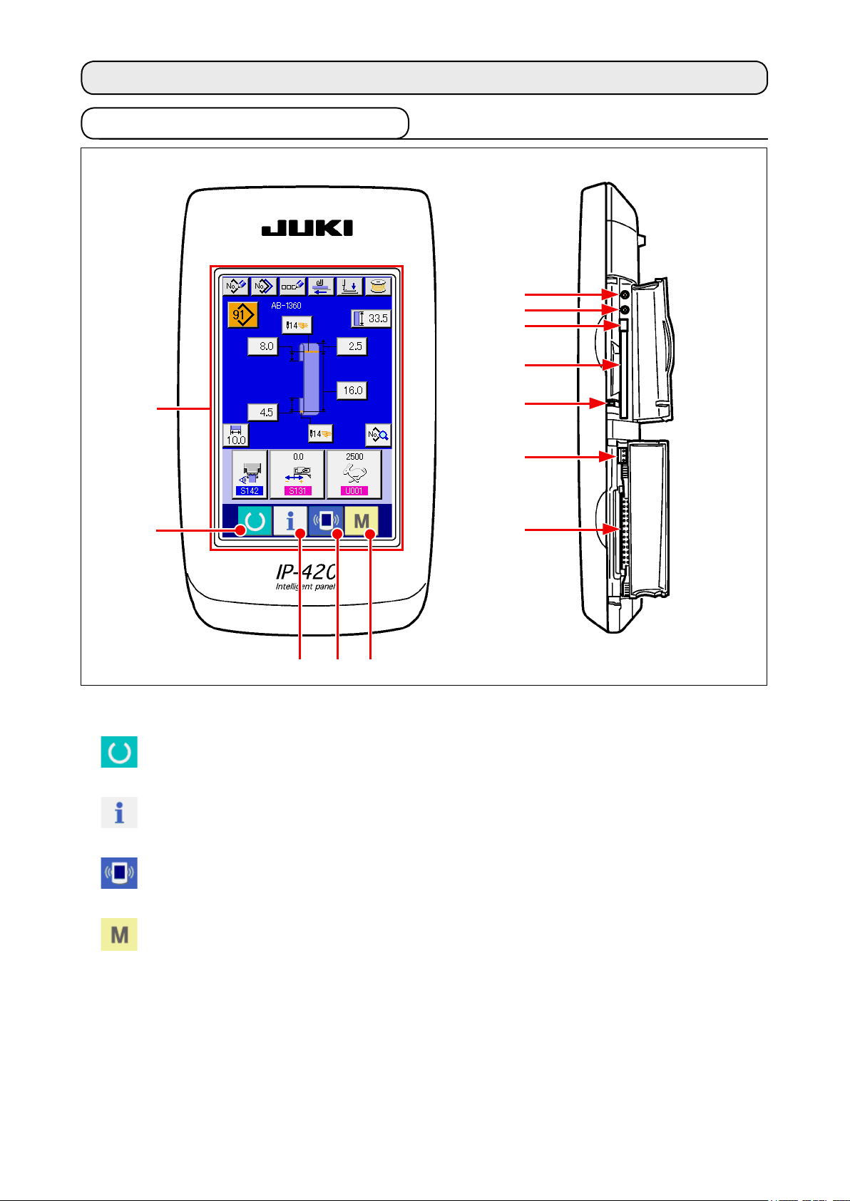
2-1. Name of each section of IP-420
①
②
(Front)
(Right side)
⑥
⑦
⑧
⑨
⑩
⑪
⑫
④ ⑤
③
Touch panel • LCD display section
①
SET READY key → Changeover of the data input screen and the sewing screen can be
②
performed.
INFORMATION key → Changeover of the data input screen and the information screen
③
can be performed.
COMMUNICATION key → Changeover of the data input screen and the communication
④
screen can be performed.
MODE key → Changeover of the data input screen and the mode changeover
⑤
screen which performs various detail settings can be performed.
Contrast control
⑥
Brightness control
⑦
CompactFlash (TM) eject button
⑧
CompactFlash (TM) slot
⑨
Cover detection switch
⑩
Connector for external switch
⑪
Connector for control-box connection
⑫
– 25 –
Page 31

2-2. Buttons to be used in common
The buttons which perform common operations in each screen of IP-420 are as follows:
CANCEL button → This button closes the pop-up screen.
In case of the data change screen, the data being
changed can be cancelled.
ENTER button → This button determines the changed data.
UP SCROLL button → This button scrolls the button or the display in the up-
ward direction.
DOWN SCROLL button → This button scrolls the button or the display in the
downward direction.
RESET button → This button performs the release of error.
NUMERAL INPUT button → This button displays ten keys and input of numerals
can be performed.
CHARACTER INPUT button → This button displays the character input screen.
→ Refer to
pattern number" p.41
PRESSER LOWERING button → Presser is lowered, and the presser lowering screen is
displayed. To lift presser, press presser lift button dis-
played in the presser lowering screen.
Bobbin winder button → Bobbin thread winding is performed.
→ Refer to
"II-2-9. How to name a shoelace loop
.
"I-5-2. Winding a bobbin" p.15
.
– 26 –
Page 32

2-3. Basic operation of IP-420
①
When the power is turned ON rst, the language selection
②
When SET READY key A is pressed, the back color of
Turn ON the power switch
screen is displayed. Set the language you use. (It is possible to
change with Memory switch ).
When ending the selection screen with CANCEL but-
ton or ENTER button without performing the
language selection, the language selection screen is
displayed whenever the power is turned ON.
Press SET READY key to move on to the sewing ready
state
LCD display is changed to green, and the sewing machine is set
to the sewing possible state.
A
– 27 –
Page 33

2-4. LCD section when the shoelace loop individual sewing is selected
(1) Shoelace loop individual sewing data entry screen
J
A
G
K
B
K
I
M
A
B C D E F
L
K
H
N
Symbol
A
B
C
D
E
F
Name of button Description
New pattern creating
button
Copy button Displays the copy source shoelace loop pattern number selection screen to allow
Character input button Displays the shoelace loop individual sewing character entry screen to allow entry
Feed button Insert a shoelace loop into the loop feeder unit and press this button to feed the
Presser lowering button The machine lowers the garment body presser and the work clamp foot and
Bobbin winding button Displays the bobbin winding screen to allow the machine to wind a bobbin.
Displays the new shoelace loop pattern number creation screen to allow registration
of new pattern data.
→ Refer to
copying of pattern data.
→ Refer to
of the name of pattern data.
→ Refer to
shoelace loop.
displays the presser lowering screen.
→ Refer to
foot" p.34
→ Refer to
"II-2-8. How to register a new shoelace loop pattern number" p.39
"II-2-11. How to copy a shoelace loop pattern number" p.44
"II-2-9. How to name a shoelace loop pattern number" p.41
"II-2-6. How to lower the garment body presser and the work clamp
.
"I-5-2. Winding a bobbin" p.15
.
.
.
.
– 28 –
Page 34

Symbol
Name of button Description
Pattern number list
G
button
Sewing data list button Displays the sewing data list screen. Detailed sewing data which is not displayed on
H
Shoelace loop width
I
button
Bartacking button Displays the LK individual data entry screen to shift to the bartacking setting mode.
J
Shoelace loop length
K
button
Shoelace loop length
L
input button
Sewing data
M
customization button
Displays the shoelace loop pattern number list screen to allow selection of pattern
data.
→ Refer to
the entry screen can be selected to edit sewing data.
Displays the shoelace loop width setting screen.
The number of buttons to be displayed on the screen differs with the sewing shape.
The number of stitches and the types of sewing shape (linear bartacking or zigzag
bartacking) will be displayed on the button.
→ Refer to
Displays the shoelace loop length setting screen. The buttons are displayed
according to the sewing shape and the settable shoelace loop length that can be
set. The number of buttons to be displayed on the screen differs with the sewing
shape.
Displays the shoelace loop length entry screen.
Displays the sewing data setting screen specied on the customization setting
screen of the data entry screen.
"II-2-10. How to select a shoelace loop pattern number" p.42
"II-2-14. How to carry out the bartacking setting" p.49
.
.
N
Symbol
A
B
Sewing data / adjustment
data customization
screen
Name of image Description
Name of shoelace loop
individual sewing data
Sewing shape display Sewing shape is displayed.
Displays the sewing data setting screen or the adjustment data setting screen
specied on the customization setting screen of the data entry screen.
Displays the name entered in the shoelace loop individual sewing data which is
currently selected.
– 29 –
Page 35

(2) Shoelace loop individual sewing screen
A
G
H
C
J
I
B C DA
E
D
E
B
F
Symbol
A
B
C
D
E
F
Name of button Description
Setback operation button Carries out the setback operation.
Next loop clamping
cancel button
Feed button When this button is pressed with a shoelace loop inserted into the loop feeder unit,
Presser lowering button The machine lowers the garment body presser and the work clamp foot and displays
Shoelace loop tension
button
Step operation button Displays the step operation selection screen and shifts to the step operation mode.
The machine carries out prohibition (cancel) or reset of loop clamping for the next
sewing.
→ Refer to
sewing" p.48
the feeder unit feeds the shoelace loop. It should be remembered, however, this
button cannot be pressed while the sewing machine is engaged in sewing or carries
out setback operation.
the presser lowering screen. It should be remembered, however, this button cannot
be pressed while the sewing machine is engaged in sewing or carries out setback
operation.
→ Refer to
foot" p.34
Displays the shoelace loop tension entry screen. At this time, the start switch action
will be prohibited.
It should be remembered, however, this button cannot be pressed while the sewing
machine performs the setback operation.
→ Refer to
"II-2-13. Function of canceling of a loop clamping for the next
.
"II-2-6. How to lower the garment body presser and the work clamp
.
"II-2-12. How to carry out the step operation" p.45
.
– 30 –
Page 36

Symbol
Name of button Description
Counter value change
G
button
Counter changeover
H
button
Direct-pattern next page
I
button
Direct pattern button Displays the shoelace loop pattern number specied on the direct pattern selection
J
Displays the current counter value on the button. When this button is pressed, the
counter value change screen is displayed.
→ Refer to
Bartacking counter display/shoelace loop counter display/bobbin thread counter
display can be changed over.
The button is displayed only in the case two or more of the aforementioned
counters are in the ON state.
: Bartacking counter
: Shoelace loop counter
: Bobbin thread counter
→ Refer to
Displays shoelace loop pattern numbers registered on the next page on J section.
screen.
"II-2-7. Using counter" p.35
"II-2-7. Using counter" p.35
.
.
Be aware that a press on this button activates the work
clamp foot and the garment body presser.
Symbol
A
B
C
D
E
Name of image Description
Shoelace loop pattern
number
Shoelace loop pattern
description
Shoelace loop width Displays the shoelace loop width which is currently set.
Name of shoelace loop
individual sewing data
Sewing speed Displays the sewing speed (set value) of the bartacking pattern which is being
Displays the shoelace loop pattern number which is currently selected.
Displays the description (sewing shape, dimensions) of the shoelace loop pattern
to be sewn.
Displays the name entered in the shoelace loop individual sewing data which is
currently selected.
sewing.
– 31 –
Page 37

2-5. How to change the shoelace loop length
(1) How to change the shoelace loop dimensions
Displaying the shoelace loop individual sewing data entry
①
screen
The shoelace loop dimensions can be changed on the shoelace
loop individual sewing data entry screen. On the sewing screen
of the shoelace loop individual sewing (green), press the set
A
B
ready key to display the shoelace loop individual sewing
data entry screen (blue).
Bringing up the shoelace loop length entry screen
②
When you press the button for the shoelace loop length you
want to change, the corresponding shoelace loop length entry
screen is displayed.
Change the shoelace loop length A as an example.
Press button A to display the shoelace loop length entry
screen.
Entering data
③
Enter a desired value with numeric keys and +/− button B.
Conrming your entry
④
Press enter button C, and the data you have entered is
C
conrmed.
* For the other shoelace loop lengths, you can change the data
following the steps of procedure described above.
The dimensions of the shoelace loop sewing shape
displayed on the operation panel are only for reference. The dimensions vary according to the shoelace
loop material. Be sure to adjust the settings of shoe-
lace loop dimensions so that your desired nished
dimensions are achieved.
– 32 –
Page 38

(2) Changing the shoelace loop length (entire length) and precautions to be taken
When you press button F, the shoelace loop length (entire
length) entry screen is displayed to allow you to change shoelace
F
loop length (entire length).
Enter the desired value with +/− button G . Then conrm your entry
with enter button H.
In the case the shoelace loop length (entire length) is
changed, the nal dimension (shoelace loop length F)
will change. So, be careful.
G
H
– 33 –
Page 39

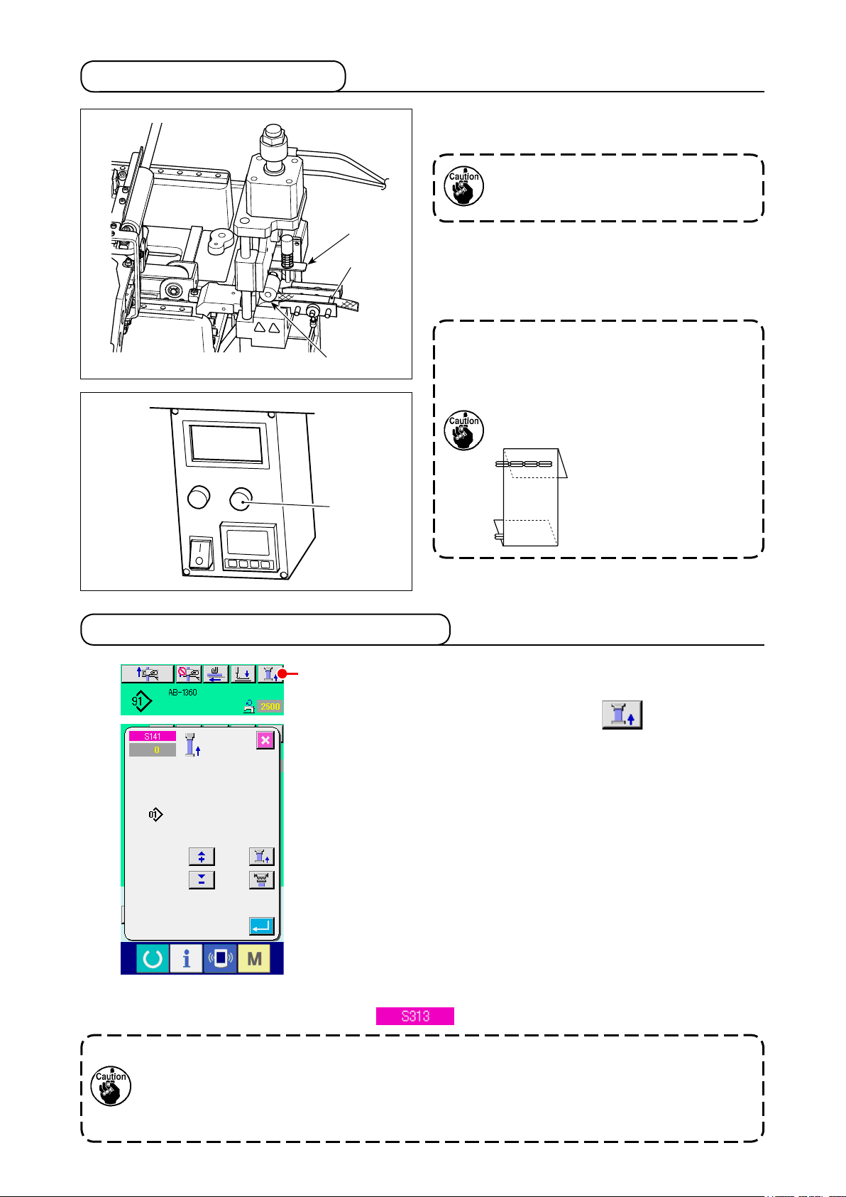
2-6. How to lower the garment body presser and the work clamp foot
A
When you press presser lowering button A on the shoelace loop individual sewing data entry screen (blue) on the sewing
screen of the shoelace loop individual sewing (green), the presser
lowering screen is displayed.
Even if you press the presser lowering button immediately after turning the power ON, the error buzzer will
sound and the presser lowering will not start.
Press set ready key to retrieve the origin to bring
up the sewing screen before pressing the presser lowering button.
When you press presser lowering button A, the sewing machine carries out the following operation and displays the presser
lowering screen.
The garment body presser comes down and moves backward.
B
The work clamp foot of the machine head comes down.
When you press presser lifting button B on the presser lowering screen, the sewing machine carries out the following opera-
tion and goes back to the entry screen (or sewing screen).
The garment body presser moves forward and goes up.
The work clamp foot of the machine head goes up.
When you press presser lowering button
or lifting button
machine head and the garment body presser operate
respectively. Take care not to allow your hands to be
caught by the garment body presser and the work
clamp foot.
, the work clamp foot of the
B
A
– 34 –
Page 40

2-7. Using counter
(1) Setting procedure of the counter
①
Display the counter setting screen
A
B
C
D
Press switch and the COUNTER SETTING button
is displayed on the screen. When this button is pressed, the
A
counter setting screen is displayed.
Selection of kinds of counters
②
This sewing machine has four different counters; i.e., the bart-
acking counter, shoelace loop counter, No. of pcs. counter and
bobbin thread counter.
E
When BARTACKING COUNTER TYPE SELECT button B,
SHOELACE LOOP COUNTER TYPE SELECT button C
or NO. OF PCS. COUNTER TYPE SELECT button D is
pressed, the corresponding counter type select screen is dis-
played. On this screen the counter type can be selected individ-
ually.
To set the bobbin thread counter, press page changeover button
F G
H
E to change over the page shown on the screen. Then,
press the bobbin thread counter type selection button F
to display the counter type selection screen.
– 35 –
Page 41

[Bartacking counter]
UP counter:
Every time the sewing machine sews a bartack, the counter
increases its current value by one. When the current value equals
to the preset value, the count-complete screen is displayed.
DOWN counter:
Every time the sewing machine sews a bartack, the counter
decreases its current value by one. When the existing value is
reached “0”, the count-up screen is displayed.
Counter disuse:
The bartacking counter does not count a nished shape even
when the machine has sewn the shape. The counter screen of the
sewing counter is not displayed.
[Shoelace loop counter]
UP counter:
Every time the sewing machine sews a shoelace loop, the counter
increases its current value by one. When the current value equals
to the preset value, the count-complete screen is displayed.
DOWN counter:
Every time the sewing machine nishes all the shoelace loops of a
garment under the cycle sewing .mode, the counter decreases its
current value by one. When the current value reaches 0 (zero), the
count-complete screen is displayed.
Counter disuse:
The shoelace loop counter does not count a nished shape even
when the machine has sewn the shape. The counter screen of the
sewing counter is not displayed.
[No. of pcs. counter]
UP counter:
Every time the sewing machine nishes all the shoelace loops of
a garment under the cycle sewing mode, the counter increases its
current value by one. When the current value equals to the preset
value, the count-complete screen is displayed.
DOWN counter:
Every time the sewing machine sews a shoelace loop, the counter
decreases its current value by one. When the existing value is
reached “0”, the count-up screen is displayed.
Counter disuse:
The shoelace loop counter does not count a nished shape even
when the machine has sewn the shape. The counter screen of the
No. of pcs. counter is not displayed.
[Bobbin thread counter]
UP counter:
The value shown on the counter increases by one for every 10
bartacking stitches. When the current value shown on the counter
reaches the set value, the count-complete screen is displayed.
DOWN counter:
The value shown on the counter decreases by one for every 10
bartacking stitches. When the current value shown on the counter
reaches zero (0), the count-complete screen is displayed.
Counter disuse:
The bobbin thread counter does not work even the machine
performs sewing. The count-complete screen for the bobbin thread
counter will not be displayed.
– 36 –
Page 42

Change of counter set value
③
I
J
K
Press button I for the bartacking counter, button
for the shoelace loop counter, button K for the No. of
J
pcs. counter or button G for the bobbin thread counter to
display the corresponding counter set value entry screen.
Here, enter the set value.
When “0” is entered in the set value, the display of count-up
screen is not performed.
L
M
N
Changing the current value on the counter
④
Press button L for the bartacking counter, button
for the shoelace loop counter, button N for the No. of
M
pcs. counter or button H for the bobbin thread counter to
display the corresponding counter current value entry screen.
Here, enter the existing value.
– 37 –
Page 43

(2) Count-up releasing procedure
When the count-up condition is reached during sewing work, the
count-up screen is displayed and the buzzer beeps. Press CLEAR
button A to reset the counter and the screen returns to the
sewing screen. Then the counter starts counting again.
A
(3) How to change the counter value during sewing
Display the counter value change screen
①
When you desire to revise the counter value during sewing
work due to the mistake or the like, press COUNTER VALUE
A
B
CHANGE button A on the sewing screen. The counter
value change screen is displayed.
Change the counter value
②
Enter the value you desire with ten keys, or “+” or “-“ key B.
D
Determine the counter value
③
When ENTER button C is pressed, the data is deter-
mined.
When you desire to clear the counter value, press CLEAR but-
ton D.
C
– 38 –
Page 44

2-8. How to register a new shoelace loop pattern number
This section describes how to create a new shoelace loop pattern using the following shoelace loop pattern as an example.
Pattern number 15
Shoelace loop width 11 mm
Bartacking shape 22-stitch linear bartacking
Bartacking width 12 mm
A
Displaying the data entry screen
①
When you bring up the entry screen under the shoelace loop in-
dividual sewing mode or the shoelace loop cycle sewing mode,
new pattern creation is enabled. Press new creation button
A to display the new shoelace loop pattern number cre-
ation screen.
B
D
C
Entering a pattern number
②
Enter new pattern number 15 with numeric keys B. It is also
possible to search for an unregistered sewing pattern number
using +/− buttons (C, D).
E
When you press enter button E, the new pattern number
to create is conrmed and the shoelace loop width entry screen
is displayed.
– 39 –
Page 45

H
L
I
J
Entering a shoelace loop width
③
Enter 15 with numeric keys H or +/− buttons (I,
) to set the shoelace loop width to 11 mm. Press enter button
J
K to conrm your entry. Then, the standard pattern selec-
tion screen is displayed.
K
Selecting a standard pattern
④
Standard sewing pattern, 22-stitch bartacking with button L.
Press enter button M to conrm your entry. Then, the
bartacking information entry screen is displayed.
P
M
Entering a bartacking width
⑤
O
When you press X actual dimension value button N on
N
the bartacking information entry screen, and the rst bartacking
X actual dimension value setting screen is displayed.
Enter 12 with numeric key P or +/− buttons (Q, R)
to set the bartacking width to 12 mm. Press enter button
to conrm your entry. Then screen goes back to the bartack-
S
ing information entry screen.
Q
S
R
– 40 –
Page 46

Finishing the creation of a new pattern
⑥
When you press close button O on the bartacking informa-
tion entry screen, the screen goes back to the shoelace loop
data entry screen. Check to make sure that the parameters you
have set are included on the data entry screen.
If you press the cancel button on any of the screens
which appear on the steps of procedure beyond ③,
the screen returns to the shoelace loop data entry
screen. In this case, the values of the parameters you
have not set shown on the shoelace loop data entry
screen are their initial values.
2-9. How to name a shoelace loop pattern number
It is possible to enter as many as 14 characters for each shoelace loop pattern number.
A
Displaying the data entry screen
①
Only on the shoelace loop individual sewing data entry screen
(blue), the name of a shoelace loop pattern number can be
entered. On the sewing screen (green), press the set ready key
to display the data entry screen (blue).
Bringing up the character entry screen
②
When you press character input button A, and the char-
acter entry screen is displayed.
Entering characters
③
Characters can be entered by pressing character button B
F
corresponding to the desired character. As many as 14 alpha-
numeric characters ( to , to ) and symbols ( ,
, , and ). The cursor can be moved by means of cursor
B
C
D
E
leftward-travel button C or cursor rightward-travel button
D. If you want to delete the entered character, move the
cursor to the character to delete and press delete button E.
Finishing the entry of characters
④
When you press enter button F, the character entry is
nished. After the end of the character entry, the characters you
have entered are displayed on the upper part of the data entry
screen (blue).
– 41 –
Page 47

2-10. How to select a shoelace loop pattern number
(1) Selection on the data entry screen
Displaying the data entry screen
①
The shoelace loop pattern number can be selected on the data
A
entry screen (blue). If the sewing screen (green) is displayed,
press set ready key to display the data entry screen.
Bringing up the pattern number selection screen
②
When you press shoelace loop pattern number selection button
A, the shoelace loop pattern number selection screen is
displayed. The shoelace loop pattern number which is currently
selected and its details are displayed on the upper part of the
screen and the list of the shoelace loop pattern number buttons
is displayed on the lower part of the screen.
Selecting a shoelace loop pattern number
③
C
Every time you press up/down scroll buttons B,
the registered shoelace loop pattern number button C changes over one after another. The button indicates the details of
D
the sewing data entered for the shoelace loop pattern number.
Press shoelace loop pattern number button C corresponding to
the pattern you want to select.
B
Conrm the shoelace loop pattern number
④
E
When you press enter button D, the shoelace loop pat-
tern number selection screen is closed to nish the selection.
* If you want to delete the registered shoelace loop pattern num-
ber, press delete button E. It should be noted, however,
that the shoelace loop pattern number registered in the cycle
sewing cannot be deleted.
– 42 –
Page 48

(2) Selection by the direct button
A
CAUTION
1. Make sure without fail of the contour of the sewing pattern after selection of the sewing
pattern. If the sewing pattern extends outside the work clamp foot, the needle will
interfere with the work clamp foot.
2. Be aware that a press on the direct pattern button activates the work clamp foot and the
garment body presser.
:
Displaying the data entry screen or the sewing screen
①
When the pattern has already been registered on the direct
pattern selection screen, pattern button A is displayed on the
lower side of the sewing screen without exceptions.
Selecting the shoelace loop pattern number
②
When pattern button A is pressed, the shoelace loop pattern
number to be displayed is changed.
Display and press the button of the shoelace loop pattern num-
ber you desire to sew. When it is pressed, the shoelace loop
pattern number is selected.
– 43 –
Page 49

2-11. How to copy a shoelace loop pattern number
It is possible to copy the sewing data of a registered shoelace loop pattern number can be copied to
an unregistered shoelace loop pattern number. Overwrite copy of the shoelace loop pattern number is
prohibited. If you want to overwrite a shoelace loop pattern number, it is necessary to delete the pattern
number you do not need in advance.
→ Refer to
"II-2-10. How to select a shoelace loop pattern number" p.42
A
Displaying the data entry screen
①
Only on the shoelace loop individual sewing data entry screen
(blue) on which the pattern button is selected, the shoelace loop
pattern number can be copied. If the sewing screen (green),
is displayed, press the set ready key to display the data
entry screen (blue).
Bringing up the pattern copy screen
②
When you press pattern copy button A, the pattern but-
ton copy (selection of the source pattern to be copied) screen is
displayed.
.
B
D
Selecting a copy source pattern number
③
Select a copy source shoelace loop pattern number from shoe-
lace loop pattern number list button B.
Then, when you press copy destination input button C,
the copy destination entry screen is displayed.
C
Entering a copy destination pattern number
④
Enter a copy destination shoelace loop pattern number using
numeric keys D. It is also possible to search for an unused
shoelace loop pattern number using +/− buttons (F,
).
E
Starting copying
⑤
E
F
Press enter button G to start copy of the shoelace loop
G
pattern number. The screen will return to the shoelace loop
pattern number copy (copy source selection) screen with the
copied shoelace loop pattern number being selected.
* It is also possible to copy the cycle sewing data following the
similar procedure.
– 44 –
Page 50

2-12. How to carry out the step operation
The step operation is the function which enables step-by-step operation of the sewing machine. For the
AB-1360, two different operations, i.e., setback and sewing position can be checked by means of the
step operation.
When you press step operation button A on the sewing
screen of the shoelace loop individual sewing or of the cycle
sewing, the step operation selection screen is displayed. If the
screen displays the data entry screen (blue), press the set ready
key to display the sewing screen (green).
A
When you press setback step button B, the screen
changes to the setback step operation screen. When you press
sewing position step operation button C, screen chang-
es to the sewing position step operation screen.
B
C
– 45 –
Page 51

(1) Setback step operation
The setback operation can be operated on a step-by-step basis.
Carrying out the step operation
①
C
D
E
A
F
When you press step feed button A, the loop feeder unit
carries out one step operation. Picture E is displayed to show
the aforementioned operation process as it looks.
In addition, the step number under edition, the number of entire
B
steps D and shoelace loop pattern number F under edition are
displayed.
Finishing the step operation
②
Press cancel button C to close the screen.
Carrying out the sequential setback operation
③
If you want to carry out setback operation not on a step-by-step
basis but on the basis of sequential operation, press setback
operation button B to allow you to check the sequence of
setback operation.
(2) Sewing position step operation
The shoelace loop sewing operation can be carried out on a step-by-step basis.
Carrying out the step operation
①
C
E
F
A
G
When you press step feed button A, the loop feeder unit
N
B
carries out one step operation. Picture F is displayed to show
the aforementioned operation process as it looks.
In addition, the step number under edition, the number of entire
step E and shoelace loop pattern number G under edition are
H
I
D
displayed.
In the case of the operation step where the loop clamp
operates, the conrmation screen is displayed. Be
aware that the shoelace loop clamp goes forward if
you press the button on the conrmation screen.
Changing the sewing data
②
When you check the step operation, changeable sewing data
is displayed. Values of the XY directions can be changed by
H
means of parameter change button I.
– 46 –
Page 52

Starting sewing
③
C
When you proceed to the sewing step, message L telling that
M
the sewing can be started with the start switch is displayed. At
L
that time, thread tension button J and setting button of
J
K
max. sewing speed K are displayed. If you want to set
those values, you may change the respective values.
Press the start switch to start actual sewing.
Finishing the step operation
④
When you press cancel button C, the loop feeder unit will
move to the standby position to complete the step operation.
Conrming your entry
⑤
To conrm your entry, press enter button D. If you pro-
ceed with the step operation without pressing enter button
or terminate the step operation by pressing cancel button
D
, the data you have entered in the current step will be can-
C
celled.
Carrying out the sewing on the basis of sequential sewing
⑥
of a shoelace loop
If you want to carry out sewing of a shoelace loop not on a step-
by-step basis but on the basis of sequential sewing of a shoe-
O
lace loop, press one-function forward button B.
Then, the sewing machine will carry out a sequential operation
until the next sewing-start step. (Every time you press the but-
ton, step operation ③ is carried out.)
As with ③, the sewing machine starts sewing by a press on the
start switch.
No sewing performed
⑦
In the sewing step, if the sewing skip button M is pressed,
the machine will move on to the next step without performing
the sewing.
Step backward
⑧
When the step is desired to be moved backward, press the step
backward button N, and the system can be moved back-
ward up to the step allowed by the system.
Lifting/lowering the garment body presser
⑨
The garment body presser can be lifted/lowered by pressing
the start switch at the rst step ( O is displayed) of the
sewing position step operation.
– 47 –
Page 53

2-13. Function of canceling of a loop clamping for the next sewing
This function is used to prohibit the setback operation after the end of sewing. In the case you know that
the power to the machine will be turned off after the end of sewing, or in the case you don't need to setback the next shoelace loop so as to change over the product, this function is used to prevent the next
shoelace loop from being clamped uselessly.
A
When press button A, the button is brought to the depressed
state (ON state) to prohibit the setback operation after the
end of sewing. When one sequence of shoelace loop sewing is nished in the ON state, the button is reset (OFF state).
In addition to the end of sewing as described above,
the canceling of a loop clamping for the next sewing
(prevention of the setback operation after the end of
sewing) can be reset from the state where button A is
pressed in the following cases:
• When the button, which is in the ON state, is pressed
again (to place it in the OFF state)
• When the ready key is pressed on the sewing screen
(green) to return to the data entry screen (blue);
• When the power is turned OFF;
• When the error screen is displayed;
• When you carry out sewing using the step operation
function (the screen changes to the step operation
selection screen).
– 48 –
Page 54

2-14. How to carry out the bartacking setting
A
Changing the screen to the LK unit data entry screen
①
When you press bartacking button A on the shoelace
loop individual sewing data entry screen, the LK unit data entry
screen is displayed. You can set the bartacking on this screen.
LK unit data entry screen
– 49 –
Page 55

2-15. LCD section at the time of setting the bartacking
(1) LK unit data entry screen
A B C D
A
E
G
J
I
F
B
H
K
Symbol
A
B
C
D
Name of button Description
New user-pattern
register button
Thread clamp button Selects "enable/disable" of the thread clamp.
Presser lowering button Lowers the garment body presser and the work clamp foot and displays the presser
Bobbin winding button The bobbin winding button thread-winding screen is displayed. It should be
Displays the new user-pattern register screen.
→ Refer to
: Thread clamp is enabled
: Thread clamp is disabled
* In the case the thread clamp prohibition is selected with the memory switch U035,
the thread clamp button is not displayed.
lowering screen. It should be remembered, however, the error alarm buzzer sounds
and a press on the button is disabled if the set ready key has not at all pressed up
to that time.
→ Refer to
foot" p.34
remembered, however, the error buzzer will sound to disable the press-down
operation unless the Ready key has been pressed in prior..
→ Refer to
"II-2-21. How to register a new user-pattern" p.61
"II-2-6. How to lower the garment body presser and the work clamp
.
"I-5-2. Winding a bobbin" p.15
.
.
– 50 –
Page 56

Symbol
Name of button Description
Sewing shape selection
E
button
Actual X-direction value
F
button
Thread tension setting
G
button
Max. sewing speed
H
control setting button
Close button Displays the shoelace loop individual sewing data entry screen and enters the
I
X-travel amount setting
J
button
Displays the sewing shape which is currently selected. When you press the button,
the standard pattern number list screen is displayed in the case you have selected
a standard pattern or the user-pattern list screen is displayed in the case you have
selected a user-pattern.
→ Refer to
Displays the actual dimension value in X direction of the sewing shape which is currently
selected. When you press this button, the actual X/Y actual value setting screen is
displayed.
→ Refer to
Displays, on this button, the needle thread tension value set in the pattern data
which is currently selected. When you press the button, thread tension setting
screen is displayed.
→ Refer to
Displays the controlled max. sewing speed which is currently set on the button.
When you press the button, max. sewing speed control setting screen is displayed.
→ Refer to
shoelace loop individual sewing mode.
Displays the travel amount of the currently-selected sewing shape in X direction.
When pressed, the X-travel amount setting screen is displayed.
→ Refer to
"II-2-18. How to change the item data (bartacking setting)" p.56
"II-2-18. How to change the item data (bartacking setting)" p.56
"II-2-18. How to change the item data (bartacking setting)" p.56
"II-2-18. How to change the item data (bartacking setting)" p.56
"II-2-18. How to change the item data (bartacking setting)" p.56
.
.
.
.
.
K
Symbol
A
B
Y-travel amount setting
button
Name of image Description
Pattern number and type
of pattern
Actual Y-direction value Displays the actual dimension value in Y direction of the sewing shape which is
Displays the travel amount of the currently-selected sewing shape in Y direction.
When pressed, the X-travel amount setting screen is displayed.
→ Refer to
Displays the pattern number and the type of pattern (standard pattern/user pattern)
which are currently selected.
: Standard pattern
: User pattern
currently selected.
If the actual dimension value in Y direction is any value other than 0.0, the actual
Y-direction value button is displayed.
"II-2-18. How to change the item data (bartacking setting)" p.56
.
– 51 –
Page 57

(2) LK unit sewing screen
A
B
C
A
B
E
F
F
H
G
Symbol
A
C
D
I
E
Name of button Description
Thread clamp button Selects "enable/disable" of the thread clamp.
: Thread clamp is enabled
: Thread clamp is disabled
D
I
G
H
* In the case the thread clamp prohibition is selected with the memory switch U035,
the thread clamp button is not displayed.
Presser lowering button Lowers the work clamp foot and displays the presser lowering screen.
B
→ Refer to
foot" p.34
Thread tension setting
C
button
Counter value change
D
button
Step sewing button Displays the machine-head jump step sewing screen. You can check the pattern
E
Speed-dial setting
F
increase button
Displays, on this button, the needle thread tension value set in the pattern data
which is currently selected. When you press the button, the thread tension setting
screen is displayed.
→ Refer to
Displays the current counter value on the button. When you press the button, the
counter value change screen is displayed.
→ Refer to
shape on this screen.
→ Refer to
Increases the sewing speed in increments of 100.
"II-2-6. How to lower the garment body presser and the work clamp
.
"II-2-18. How to change the item data (bartacking setting)" p.56
"II-2-7. Using counter" p.35
"II-2-19. How to check the sewing shape" p.57
.
.
– 52 –
.
Page 58

Symbol
Name of button Description
G
H
I
Symbol
A
Speed-dial setting
decrease button
Speed-dial setting button Increases/decreases the sewing speed when the button is moved upward or
Counter changeover
button
Name of image Description
Pattern number and type
of pattern
Decreases the sewing speed in increments of 100.
downward.
Bartacking counter display/bobbin thread counter display can be changed over.
The button is displayed only in the case both the bartacking counter and bobbin
thread counter are in the ON state.
: Bartacking counter
: Bobbin thread counter
→ Refer to
Displays the pattern number and the type of pattern (standard pattern/user pattern)
which are currently selected.
"II-2-7. Using counter" p.35
.
: Standard pattern
: User pattern
B
Sewing shape Displays the sewing shape which is currently selected.
C
Number of stitches Displays the total number of stitches of the sewing shape which is currently
selected.
D
Max. sewing speed
control setting
E
Sewing speed Displays the sewing speed preset with the speed dial.
F
X actual dimension value
button
G
Y actual dimension value
button
H
X-travel amount display Displays the travel amount of the currently-selected sewing shape in X direction.
I
Y-travel amount display Displays the travel amount of the currently-selected sewing shape in Y direction.
Displays the Max. sewing speed control setting which has been set under the
setting mode.
Displays the actual dimension value, in X direction, of the sewing shape which is
currently selected.
Displays the actual dimension value, in Y direction, of the sewing shape which is
currently selected.
– 53 –
Page 59

2-16. How to select the sewing shape (bartacking setting)
Displaying the data entry screen
①
Only on the data entry screen (light blue), the sewing shape se-
lection is enabled. On the sewing screen (green), press the set
A
C
B
ready key to the data entry screen (light blue).
Bringing up the sewing shape selection screen
②
When you press sewing shape selection button A, the
sewing shape selection screen is displayed.
Selecting the desired type of sewing shape
③
The following two different types of sewing shapes are avail-
able. If you want to change the standard pattern to the user
pattern or vice versa, press sewing shape type selection but-
ton B.
E
Pictograph Name Max. number of patterns
Standard pattern 2
D
Selecting the sewing shape
④
User pattern 200
Press sewing shape button C which corresponds to the one
you want.
F
Conrming the sewing shape
⑤
Press enter button D to conrm the sewing shape you
have selected. Then, the data entry screen is displayed.
In the case you have selected the user pattern, the screen at
left is displayed. Pattern number selection button E appears on
the screen. Press the pattern number button which corresponds
to the one you want.
If you want to check the sewing shape you have selected, press
viewer button F. Then, the viewer screen is displayed to
show the sewing shape you have selected.
– 54 –
Page 60

2-17. List of sewing shapes
Sewing size (mm)
No. Needle-entry diagram Number of stitches
Length Width
1 14 0 12.0
2 22 0 12.0
* The sewing size indicated applies when the enlargement factor is 100 %.
– 55 –
Page 61

2-18. How to change the item data (bartacking setting)
Displaying the data entry screen
①
On the data entry screen, the item data can be changed. On the
A
B
sewing screen (green), press the set ready key to display
the data entry screen (light blue).
C
E
* The thread tension value can also be changed on the sewing
D
F
screen.
Displaying the item data entry screen
②
When the item data button corresponding to the item you want
to change is pressed, the item data entry screen is displayed.
There are following six data items.
Item Input range Initial value
A X actual dimension value 6.0 to 14.0 (mm) 10.0 (mm)
B Y actual dimension value 0.0 to 3.2 (mm) 0.0 (mm)
C Thread tension 0 to 200 50
D Max. sewing speed control 400 to 2,500 (sti/min) 2,500 (sti/min)
E
X travel amount
F
Y travel amount
−23.0 to 23.0 (mm) 0.0 (mm)
−3.2 to 3.2 (mm) 0.0 (mm)
* The maximum input range and initial value of max. limiting
speed D depend on the memory switch .
* Even if the set value of the X/Y travel amount falls within the
input range, the actual sewing range may reach the travel limits of the sewing machine. In this case, the out-of-range error
E042 will occur.
G
For example, the X actual dimension value entry procedure is
as follows.
Press A to display the item data entry screen.
Entering data
③
Enter a desired value with the numeric keys and +/− buttons G.
Conrming your entry
④
When you press enter button H, the data you have en-
tered is conrmed.
* For the other item data, data can be changed in the similar
procedure.
* X/Y values of the X/Y actual dimension values can be entered
H
· If you turn OFF the power to the sewing machine without having pressed the set ready
key, the set values of the pattern number, X/Y actual dimension values, the max. sewing
speed, thread tension and X/Y travel amount will not be stored in memory.
· If you change the Y travel amount, the dimensions between bartacks will change.
· Be sure to check the sewing shape by means of the machine head jump step sewing
after having changed the X/Y travel amount. If the sewing range exceeds the work clamp
foot, the needle can come in contact with the work clamp foot during sewing resulting in
needle breakage.
on one and the same screen.
– 56 –
Page 62

2-19. How to check the sewing shape
CAUTION
After the pattern selection, be sure to check the shape of the sewing pattern you have
selected at all times. If the pattern size is larger than the work clamp foot, the needle can
interfere with the work clamp foot during sewing resulting in needle breakage.
:
Displaying the sewing screen
①
Bring up the data entry screen (light blue). When you press the
set ready key , the background color of the LCD changes
from blue to green. On this screen, sewing is enabled.
Displaying the machine-head jump step sewing screen
②
When you press step sewing button A, the machine-head
jump step sewing screen is displayed.
A
B
Lowering the work clamp foot by means of the start switch
③
D
Performing jump sewing with the work clamp foot lowered
④
Check the sewing shape by means of the work clamp foot back-
In this mode, the sewing machine will not start even if
you press the start switch.
ward button B and work clamp foot forward button C.
When you keep either button held pressed, the work clamp foot
C
E
F
keeps moving even if you release your nger from the button.
When you want to stop the work clamp foot, press stop button
F When you press "move to initial position" button
, the screen is closed and the LK unit sewing screen is dis-
E
played.
If you press the work clamp foot forward/backward
button with the needle bar lowered, the work clamp
foot will automatically lift the needle bar to its upper
position before moving. Be careful.
Finishing checking the sewing shape
⑤
When you press cancel button D, the screen returns to the
sewing screen.
– 57 –
Page 63

2-20. How to change the thread tension command from needle entry
point to needle entry point
(1)
How to add/change the thread tension command from needle entry point to needle entry point
Displaying the thread tension command change screen
①
Press thread tension button A on the sewing screen
when you select a user pattern to display the thread tension
setting screen. When you press thread command change button
A
If the start switch is pressed, the work clamp foot will be low-
B on the thread tension setting screen, the thread ten-
sion command change screen is displayed.
ered.
In this mode, the sewing machine will not start even if
you press the start switch.
I
C
E
B
Specifying the location of the command to be changed
②
Specify the location to which a new thread tension command
you want to add, or at which the current thread tension command value you want to change by means of 1-stitch backward
button C or 1-stitch forward button D with the work
clamp foot lowered.
You can also move the needle entry point to another one, before
D
H
G
F
or after the current point, at which a thread tension command
value is set by means of E or F. To stop moving
the needle entry point, press stop button G.
When you press return-to-origin button H, the screen is
closed and displays the LK unit sewing screen.
The values shown on the screen are absolute values (thread
tension value + Thread tension command value).
– 58 –
Page 64

Entering a thread tension command value
③
When you press command input button A, the thread
tension increase/decrease value entry screen is displayed. En-
ter a desired value using the numeric keys and +/− buttons J.
When you press enter button K, your entry is conrmed.
J
K
(2) How to delete the thread tension command from needle entry point to needle entry point
Displaying the thread tension command change screen
①
Press thread tension button A on the sewing screen
A
when you select a user pattern to display the thread tension
setting screen. When you press thread command change button
B on the thread tension setting screen, the thread ten-
sion command change screen is displayed.
B
– 59 –
Page 65

I
C
E
Specifying the location of the command to be deleted
②
Specify the location of the command you want to delete by
means of 1-stitch backward button C or 1-stitch forward
button D with the work clamp foot lowered.
You can also move the needle entry point to another one, before
D
L
H
G
F
or after the current point, at which a thread tension command is
set by means of E or F. To stop moving the nee-
dle entry point, press stop button G.
When you press "move to initial position" button H, the
screen is closed and the LK unit sewing screen is displayed.
In the case the current needle entry point is located on the
thread tension command, command delete button L is
displayed.
Deleting the thread tension command
③
When you press command delete button L, the com-
M
mand delete screen is displayed. When you press enter button
M, the command is deleted.
– 60 –
Page 66

2-21. How to register a new user-pattern
A
Displaying the data entry screen
①
Only on the data entry screen (light blue), a new pattern can be
registered. On the sewing screen (green), press the set ready
key to display the data entry screen (light blue).
Bringing up the new user-pattern register screen
②
When you press new register button A, the new user-pat-
tern register screen is displayed.
Entering a user pattern number
③
Enter a new user-pattern number you want to register with
numeric keys B. If you enter the user pattern number which
has already been used, E403 will be displayed when you press
E
enter button E. In this case, select another user pattern
B
D
C
number which has not been used. It is prohibited to register a
new user-pattern to the user pattern number which has already
been used.
It is also possible to search user pattern numbers by means of
+/− buttons (C, D).
Conrming the user pattern number
④
When you press enter button E, the new user pattern
number to be registered is conrmed. Then, the data entry
screen for the user-pattern selection is displayed.
– 61 –
Page 67

2-22. How to change the sewing mode
Selecting the sewing mode
①
When you press the switch in the state where a pattern
A
has already been selected, sewing mode selection button
is displayed on the screen. When you press this button, the
A
sewing mode is changed over between the individual sewing
mode and the cycle sewing mode.
* The look of the sewing mode selection button varies according
to the sewing mode which is currently selected.
When the individual sewing is selected:
When the cycle sewing is selected:
– 62 –
Page 68

2-23. LCD section when the cycle sewing is selected
This model of sewing machine is able to sew shoelace loops sequentially with several different pieces
of shoelace loop pattern data combined. As many as 30 different shoelace loop patterns can be entered
in a cycle. Use the cycle sewing for sewing shoelace loops of two or more different sewing shapes for
one apparel product.
As many as 20 different pieces of cycle sewing data can be registered. Use the cycle sewing by creating a new sewing cycle or copying the existing one according to your need.
→ Refer to
"II-2-8. How to register a new shoelace loop pattern number" p.39
to copy a shoelace loop pattern number" p.44.
(1) Cycle sewing data entry screen
"II-2-11. How
and
B
G
A
H
A B C E F
D
I
J
K
L
M
N
Symbol
A
B
C
D
E
Name of button Description
Cycle-sewing new data
register button
Cycle-sewing data copy
button
Cycle-data name input
button
Feed button Insert a shoelace loop into the loop feeder unit and press this button. Then the unit
Presser lowering button Lowers the garment body presser and the work clamp foot and displays the presser
Displays a new cycle-sewing data number register screen.
→ Refer to
Displays the cycle-sewing shoelace loop pattern number copy screen.
→ Refer to
Displays the cycle-sewing data name entry screen.
→ Refer to
feeds the shoelace loops.
lowering screen.
→ Refer to
foot" p.34.
"II-2-8. How to register a new shoelace loop pattern number" p.39.
"II-2-11. How to copy a shoelace loop pattern number" p.44.
"II-2-9. How to name a shoelace loop pattern number" p.41.
"II-2-6. How to lower the garment body presser and the work clamp
– 63 –
Page 69

Symbol
F
Name of button Description
Bobbin winding button Enables bobbin winding
→ Refer to
"I-5-2. Winding a bobbin" p.15.
Cycle-sewing data
G
number selection button
Pattern selection button
H
Next-page display button Displayed when the number of shoelace loop patterns registered in the cycle sewing
I
Cycle-sewing sewing
J
data list button
Scroll up button Scrolls up the shoelace loop pattern number to display the previous one.
K
Scroll down button Scrolls down the shoelace loop pattern number to display the next one.
L
Step insert button Inserts a step just before the shoelace loop pattern number which is currently
M
Step delete button Deletes the step which is currently selected.
N
Displays, on the button, the cycle-sewing data number which is currently selected.
When you press the button, the cycle-sewing data number selection screen is
displayed.
A
Displays, on the button, the shoelace loop pattern numbers registered in the order
of sewing sequence and their shoelace loop shapes. Displays the shoelace loop
pattern data entry screen.
* Button pictograph/display of button H or A is shown by the number of entered
shoelace loop patterns.
data becomes 8 or more.
Displays the cycle-sewing sewing data list screen.
selected.
Symbol
A
B
Name of image Description
Order of sewing Displays the order of sewing of shoelace loot pattern data which is being entered.
If the screen is changed over to the sewing screen, the shoelace loop pattern to be
sewn rst will be displayed in blue.
* Button pictograph/display of button H or A is shown by the number of entered
shoelace loop patterns.
Cycle-sewing data name Displays the name enter into the cycle-sewing data which is currently selected.
– 64 –
Page 70

(2) Sewing screen of the cycle sewing
A
B
C
F
G
D
A B D EC
E
F
G
H
H
I
J
Symbol
A
B
C
D
E
F
Name of button Description
Setback operation button Carries out the setback operation.
Next loop clamping
cancel button
Feed button When you press draw-out this button after having inserted a shoelace loop into the
Presser lowering button Lowers the garment body presser and the work clamp foot and displays the presser
Shoelace loop tension
button
Counter value change
button
The machine carries out prohibition (cancel) or reset of loop clamping for the next
sewing.
→ Refer to
sewing" p.48.
loop feeder unit, the loop feeder unit draws out the shoelace loop.
However, a press on this button is disabled during sewing or setback operation.
lowering screen.
However, a press on this button is disabled during sewing or setback operation.
→ Refer to
foot" p.34.
Displays the shoelace loop tension entry screen. At this time, the start switch action
will be prohibited.
Displays the current counter value on the button. When you press the button, the
counter value change screen is displayed.
→ Refer to
"II-2-13. Function of canceling of a loop clamping for the next
"II-2-6. How to lower the garment body presser and the work clamp
"II-2-7. Using counter" p.35.
– 65 –
Page 71

Symbol
G
Name of button Description
Counter changeover button Bartacking counter display / shoelace loop counter display / No. of pcs. counter
display / bobbin thread counter display can be changed over.
The button is displayed only in the case two or more of the aforementioned
counters are in the ON state.
: Bartacking counter
: Shoelace loop counter
: No. of pcs. counter
: Bobbin thread counter
H
I
J
Symbol
A
B
"II-2-7. Using counter" p.35.
Order-of-sewing backward
button
→ Refer to
Restores the shoelace loop pattern to be sewn to the previous one.
Be aware that a press on this button activates the work
clamp foot and the garment body presser.
Order-of-sewing forward
button
Restores the shoelace loop pattern to be sewn to the next one.
Be aware that a press on this button activates the work
clamp foot and the garment body presser.
Step operation button Displays the step operation selection screen and enables the step operation
mode. While the machine is carrying out the set-back operation, however, this
button is disabled even if it is pressed.
→ Refer to
Name of image Description
Cycle-sewing data number Displays the cycle-sewing data number which is currently selected.
Shoelace loop pattern
number
Displays the shoelace loop pattern number which is currently selected.
"II-2-12. How to carry out the step operation" p.45.
C
Shoelace loop pattern
description
D
Shoelace loop width Displays the shoelace loop width which is currently set.
E
Cycle-sewing data name Displays the name enter into the cycle-sewing data which is currently selected.
F
Sewing speed Displays the sewing speed (set value) for the bartacking pattern which is being
G
Order of sewing Displays the order of sewing which is being carried out.
H
Display of the total number
of registered patterns
Displays the description of the shoelace loop pattern to be sewn.
sewn.
Displays the total number of shoelace loop patterns registered in the cyclesewing data number which is being sewn.
– 66 –
Page 72

2-24. How to carry out cycle sewing
It is necessary rst to change sewing mode to the cycle sewing before setting data.
→ Refer to
(1) Selection of the cycle-sewing data
A
"II-2-22. How to change the sewing mode" p.62.
Displaying the data entry screen
①
Only on the data entry screen (pink), the cycle-sewing data
number can be selected. On the sewing screen (green), press
the set ready key to display the data entry screen (pink).
Bringing up the cycle-sewing data number selection screen
②
When you press cycle-sewing data number button A, the
cycle-sewing data number selection screen is displayed. The
cycle-sewing data number which is currently selected and its
description are displayed on the upper part of the screen. The
other registered cycle-sewing data numbers and buttons are
displayed on the lower part of the screen.
C
Selecting the cycle-sewing data number
③
Every time you press upper/lower scroll buttons B,
E
the cycle-sewing data number button C changes over one after
another.
F
It is also possible to bring up the cycle-sewing data number en-
D
B
try screen with numeral input button D and directly enter
the cycle-sewing data number.
Now, press cycle-sewing data number button C you want to
select.
When you press step conrmation buttons E, sew-
ing shape, etc. registered in the cycle-sewing data are displayed
one after another.
Conrming the cycle sewing data number
④
When you press enter button F, the cycle-sewing data
number selection screen is closed to nish selection.
– 67 –
Page 73

(2) Method to create the cycle-sewing data
Displaying the data entry screen
①
Only on the data entry screen (pink), the cycle-sewing data
number can be selected. On the sewing screen (green), press
A
the set ready key
Since no pattern number is registered in the initial screen, the
rst pattern selection button is displayed in the blank state.
Displaying the pattern number selection screen
②
to display the data entry screen (pink).
C
When you press pattern selection
, the pattern number
A
selection screen is displayed.
Selecting a pattern number
③
Every time you press up/down scroll buttons
registered pattern number button C changes over one after
another.
It is also possible to bring up the pattern number entry screen
with numeral input button
E
D
number.
The button displays the description of the pattern data.
and directly enter the pattern
D
Now, press pattern number button you want to select.
B
Conrmingthepatternnumber
④
When you press enter button
, the pattern number se-
E
lection screen is closed to nish selection.
Repeating steps of procedure
⑤
through ④ by the number
②
of patterns you want to register
Once the rst registration is conrmed, the 2nd pattern selection
button
will be displayed.
F
B
, the
H
F
Repeat steps of procedure
through ④ by the number of pat-
②
terns you want to register.
You can select the pattern number button by pressing up/down
scroll buttons
is displayed in pink
When you press pattern number button H shown on the display,
. The selected patter number button
G
.
the shoelace loop pattern data entry screen is displayed. On this
screen, you can set each parameter of the pattern data separately.
If you change the parameter on the shoelace loop pattern data
I
entry screen of the cycle sewing screen, the parameter of the
original shoelace loop pattern will be changed. When setting a
parameter, the conrmation screen M589 is displayed. Press
G
enter button
changing the parameter.
as long as no problem will be caused by
E
→ Refer to "II-2-5. How to change the shoelace loop length"
p.32 for details.
When the combined data you have created requires several
screens, you can display the next screen with screen scroll but-
ton
.
I
– 68 –
Page 74

(3) Method to insert the cycle-sewing data
Determining the insertion position
①
When you press pattern number insert button A, a
sewing step is inserted into the location between the previous
pattern number and the pattern number which is being selected
(displayed in pink). Determine location C into which a sew-
C
B
A
ing step is to be inserted by means of up/down scroll buttons
Selecting the pattern number to be inserted and conrming
②
it
When you press pattern number insert button A, the pat-
tern number list screen is displayed.
Carry out steps of procedure ③ through ④ described in
Method to create the cycle-sewing data" p.68.
Once you have conrmed the pattern number, the selected pat-
tern number is displayed at the determined location of insertion.
B and press pattern number insert button A.
"(2)
– 69 –
Page 75

(4) Method for deleting the cycle sewing data
Selecting the cycle sewing data number
①
Carry out steps of procedure ① to ③ described in
tion of the cycle-sewing data" p.67
sewing data you want to delete.
B
Deleting the cycle sewing data
②
When you press date delete button A, the cycle sew-
ing data delete conrmation popup window will appear on the
"(1) Selec-
to display the cycle
A
screen. If you press B on the popup window, the cycle
sewing data you have selected is deleted.
(5) Method for deleting a step of the cycle sewing data
Selecting the cycle sewing data number
①
Carry out steps of procedure ① to ② described in
lection of the cycle-sewing data" p.67
B
sewing data which contains the step you want to delete in the
selected state.
A
Displaying the pattern number selection screen
②
Press up/down scroll buttons A to place the pattern
selection button of the step you want to delete in selected state
C
B, and press step delete button C. Then, the data
"(1) Se-
to place the cycle
step delete popup window is displayed.
Deleting the step of the cycle sewing data you want to de-
③
E
lete
When you press enter button D, the selected step of the
cycle sewing data is deleted.
If you press cancel button E, the screen returns to the cy-
cle sewing data entry screen without deleting the selected step.
D
– 70 –
Page 76

2-25. How to edit the sewing data
(1) Method for changing the sewing data
Displaying the entry screen
①
When you bring up the data entry screen for the shoelace loop
individual sewing mode or the shoelace loop cycle-sewing
mode, you can change the sewing data.
A
Selecting the sewing data to be changed
②
When you press sewing data list button A, the sew-
ing data list screen is displayed. Select the data you want to
C
B
change.
Select data item button C you want to change by pressing up/
down scroll buttons B.
Changing the sewing data
③
Sewing data consists of two different types of data items; one
type of data item requires changing of the numeric data, and the
other type of data item requires changing of the pictograph.
The data item requiring changing of the numeric data is as-
signed with a number such as displayed in pink. The
numeric data can be changed by means of the numeric keys
and +/− buttons shown on the data change screen.
The data item requiring changing of the pictograph is assigned
with a number such as displayed in blue. The pictograph can be selected from those shown on the change screen.
* Refer to
"(2) Sewing data list" p.72
for the details of sew-
ing data.
If you turn OFF the power to the sewing machine without having pressed the set ready key, the set values of
the sewing data will not be stored in memory.
The dimensions of the shoelace loop sewing shape
displayed on the operation panel are only for reference.
The dimensions vary according to the shoelace loop
material. Be sure to adjust the settings of shoelace loop
dimensions so that your desired nished dimensions
are achieved.
– 71 –
Page 77

(2) Sewing data list
No. Item
Loop length A for shoelace loop sewing shape
*
Loop length B for shoelace loop sewing shape
*
Loop length E for shoelace loop sewing shape
*
Loop length F for shoelace loop sewing shape
*
Correcting the loop length
This data number is used for correcting the length of
loop to be cut by the loop feeder unit. When the type
of loop is changed, adjust the loop length to the one
displayed on the panel using this sewing data number.
Shoelace loop width
*
*
When the shoelace loop width is changed, the
bartacking width is automatically changed according to
the new shoelace loop width. At this time, the bartacking
width out-of-range error (E435) can take place for some
set values of the shoelace loop width.
Shoelace loop length
Clamp position correction in lateral direction
This switch is used to correct the lateral position of the
shoelace loop clamp when sewing shoelace loops.
Clamp supply position correction in longitudinal
direction
This switch is used to correct the longitudinal position of
the shoelace loop clamp when feeding shoelace loops.
Shoelace loop tension
This switch is used to adjust the shoelace loop tension
that is applied by the shoelace loop drawing device
when the device places the shoelace loop in sewing position.
+ : Increases the shoelace loop tension
- : Decreases the shoelace loop tension
→ Refer to
for details.
Enable/disable of detection of shoelace loop drawing device
failure
"I-5-5. Adjusting the shoelace loop tension" p.17
Input range/
selection range
0 to 20.0
(mm)
10.0 to 22.0
(mm)
−1.0 to 9.0
(mm)
−10.0 to 30.0
(mm)
−10.0 to 10.0
(mm)
8.0 to 12.0
(mm)
20.0 to 70.0
(mm)
−3.0 to 3.0
(mm)
−5.0 to 5.0
(mm)
−100 to 100 −5
― Enable
Initial
value
4.5
(mm)
16.0
(mm)
2.5
(mm)
8.0
(mm)
0
(mm)
10.0
(mm)
33.5
(mm)
0
(mm)
0
(mm)
: Enable : Disable
In the case of a light-weight material, disable this function setting.
Loop cutter section feeding correction
This function reduces the loop feeding amount to be
clamped by the loop drawing device immediately after
cutting of the loop which is not clamped by the drawing
device.
* : Data marked with an asterisk (*) are not displayed on the sewing data list screen. They are displayed,
however, from the data entry screen.
: Data in a gray box are not displayed in the standard state. To display them, refer to the Engineer’s Manual.
−3.0 to 0
(mm)
– 72 –
0
(mm)
Page 78

No. Item
Correction of clamp position in lateral direction
before pulling out the fork
This data number is used to correct the clamp position
in lateral direction before pulling out the fork.
Clamp lowering operation at the loop feeding position
This data number is used to select whether the clamp is lowered or
not when feeding a loop.
: Lower : Not lower
In the case of a light-weight material, disable this function setting.
Correction of clamp position in lateral direction at
the rst sewing position
This data number is used to correct the clamp position
in lateral direction at the time of rst sewing.
Correction of clamp position in longitudinal
direction at the rst sewing position
This data number is used to correct the clamp position
in longitudinal direction at the time of rst sewing is
corrected.
Correction of fork angle when the fork moves
forward
This data number is used to correct the fork angle when
it is moved forward.
Correction of clamp position in longitudinal
direction when the fork moves forward
This data number is used to correct the clamp position
in longitudinal direction when the fork is moved forward.
Correction of garment body feeder position when
the fork moves forward
This data number is used to correct the garment body
feeder position in longitudinal direction when the fork is
moved forward.
Correction of fork angle after it has moved forward
This data number is used to correct the fork angle after
it has move forward is corrected.
Correction of clamp position in longitudinal
direction when the fork starts rotating
This data number is used to correct the fork position in
longitudinal direction when the fork starts rotating.
Correction of garment body feeder position when
the fork starts rotating
This data number is used to correct the garment body
feeder position in longitudinal direction when the fork
starts rotating.
Correction of fork angle when it starts rotating
This data number is used to correct the fork angle when
it starts rotating.
Correction of clamp position in longitudinal
direction while fork is rotating
This data number is used to correct the clamp position
in longitudinal direction while the fork is rotating.
* : Data marked with an asterisk (*) are not displayed on the sewing data list screen. They are displayed,
however, from the data entry screen.
: Data in a gray box are not displayed in the standard state. To display them, refer to the Engineer’s Manual.
Input range/
selection range
−7.0 to 7.0
(mm)
― Lower
−5.0 to 5.0
(mm)
−10.0 to 10.0
(mm)
−100 to 100 −20
−10.0 to 10.0
(mm)
−10.0 to 10.0
(mm)
−100 to 100 −5
−30.0 to 30.0
(mm)
−30.0 to 10.0
(mm)
−150 to 150 100
−100 to 10.0
(mm)
Initial
value
0
(mm)
0
(mm)
1.7
(mm)
0
(mm)
0.2
(mm)
−22.0
(mm)
−21.0
(mm)
−0.6
(mm)
– 73 –
Page 79

No. Item
Correction of fork angle while the fork is rotating
This data number is used to correct the fork angle when
it rotates until it rolls a loop partway.
Correction of clamp travel amount in longitudinal
direction when garment body feeder travels to the
2nd sewing position
This data number is used to correct the amount of travel
of the clamp in longitudinal direction when the garment
body feeder travels to the 2nd sewing position.
Correction of clamp position in longitudinal
direction when fork nishes loop rolling
This data number is used to correct the clamp position
in longitudinal direction when the fork nishes rolling of
a loop.
Correction of fork angel upon completion of loop
rolling
This data number is used to correct the fork angle when
it completes rolling of a loop.
Correction of 2nd sewing position of clamp in lateral
direction
This data number is used to correct the clamp position
in lateral direction at the time of 2nd sewing.
Correction of clamp position in longitudinal
direction after fork comes down
This data number is used to correct the clamp position
in longitudinal direction after the fork has been lowered.
Correction of clamp position in lateral direction
when removing fork (shorter)
This data number is used to correct the clamp position
in lateral direction when the shorter-side fork pin is
removed.
Correction of clamp position in longitudinal
direction when fork pulls a loop
This data number is used to correct the clamp position
in longitudinal direction when the fork pulls a loop.
Correction of garment body feeder in longitudinal
direction when the fork pulls a loop
This data number is used to correct the garment body
feeder position in longitudinal direction when the fork
pulls a loop.
Correction of garment body feeder standby position
This data number is used to correct the standby position
of the garment body feeder.
Correction of clamp position in lateral direction after
the rst sewing
This data number is used to correct the clamp position
in lateral direction after the completion of the rst
sewing.
* : Data marked with an asterisk (*) are not displayed on the sewing data list screen. They are displayed,
however, from the data entry screen.
: Data in a gray box are not displayed in the standard state. To display them, refer to the Engineer’s Manual.
Input range/
selection range
−100 to 100 −35
−10.0 to 10.0
(mm)
−10.0 to 10.0
(mm)
−100 to 100 5
−10.0 to 10.0
(mm)
−10.0 to 10.0
(mm)
−30.0 to 10.0
(mm)
−10.0 to 30.0
(mm)
−10.0 to 3.0
(mm)
−10.0 to 10.0
(mm)
−5.0 to 5.0
(mm)
Initial
value
0
(mm)
2.5
(mm)
−0.8
(mm)
0
(mm)
13.0
(mm)
0
(mm)
−3.5
(mm)
0
(mm)
0
(mm)
– 74 –
Page 80

2-26. How to change the memory switch data
(1) Method for changing the memory switch data
Displaying the memory switch data list screen
①
When you press mode changeover key , memory switch
A
C
data button A is displayed on the screen. When you
press this button, the memory switch data list screen is displayed.
Selecting the memory switch data button data of which you
②
want to change
Press up/down scroll buttons B to select data item
button C data of which you want to change.
B
Changing the memory switch data
③
There are two types of memory switch data according to the
data changing method; one is changed by changing gures and
the other is changed by selecting a pictograph.
For data items data of which are changed with gures are as-
signed with a number in pink as .
For these items, set values can be changed with the numeric
keys and +/− buttons displayed on the data change screen. For
data items data of which are changed by selecting a pictograph
are assigned with a number in blue as . For these
data items, a pictograph can be selected from those displayed
on the screen.
* Refer to
the memory switch data.
"(2) Memory switch data list" p.76
for details of
– 75 –
Page 81

(2) Memory switch data list
No. Item
Shoelace loop clamp standby at intermediate position:
Selection of longitudinal position
With this switch, the standby position of the shoelace loop clamp in
terms of longitudinal direction at the intermediate standby position
can be selected.
If the far-side is selected, the operator has a wider space to handle
the sewing product.
: Standard : Far
Loop width/bartacking width interlocking function
This is the function that automatically changes the bartacking width
when the shoelace loop width is changed according to the change
rate of the latter.
: Enable : Disable
Heat cutter lowering time
This data number is used to set the period of time
to wait for lowering of the heat cutter (unit: msec).
Heat cutter lifting waiting time
This data number is used to set the period of time
to wait until the heat cutter starts going up after
the draw-out device has moved backward (unit:
msec).
Correction of loop feeding amount for
clamping when heat cutter is used
This data number is used to correct the feeding
amount of the loop to be clamped by the draw-out
device when the heater is used (unit: mm).
Correction of loop cutting length when heat
cutter is used
This data number is used to correct the loop
length to be cut when the heat cutter is used (unit:
mm).
Loop draw-out device backward-travel waiting
time when heat cutter is used
This data number is used to correct the lapse
of waiting time until the draw-out device moves
backward after it has released the loop (unit: mm).
Maximum sewing speed
Input range/
selection range
― Standard
― Enable
0 to 1500 800
0 to 500 0
−10.0 to 10.0 0
−30.0 to 50.0 0
0 to 500 0
400 to 2500 2500
Initial value
Sewing speed of 1st stitch
In case of with thread clamp
Sewing speed of 2nd stitch
In case of with thread clamp
Sewing speed of 3rd stitch
In case of with thread clamp
Sewing speed of 4th stitch
In case of with thread clamp
Sewing speed of 5th stitch
In case of with thread clamp
400 to 1500 1000
400 to 2500 1500
400 to 2500 2500
400 to 2500 2500
400 to 2500 2500
– 76 –
Page 82

No. Item
Thread tension of 1st stitch
In case of with thread clamp
Input range/
selection range
0 to 200 200
Initial value
Thread tension setting at the time of thread
trimming
Thread tension changeover timing at the time
of thread trimming
In case of with thread clamp
Sewing speed of 1st stitch
In case of without thread clamp
Sewing speed of 2nd stitch
In case of without thread clamp
Sewing speed of 3rd stitch
In case of without thread clamp
Sewing speed of 4th stitch
In case of without thread clamp
Sewing speed of 5th stitch
In case of without thread clamp
Thread tension of 1st stitch
In case of without thread clamp
Thread tension changeover timing at the time
of sewing start
In case of without thread clamp
Selection of reference point for pattern enlargement/reduction
0 to 200 0
−6 to 4 0
400 to 1500 400
400 to 2500 900
400 to 2500 2500
400 to 2500 2500
400 to 2500 2500
0 to 200 0
−5 to 2 −5
― Origin
: Origin : Sewing starting point
Buzzer sound can be prohibited
: Without buzzer sound
: Panel operating sound
: Panel operating sound + error
Number of stitches of thread clamp can be
delayed
Clamping timing of thread clamp can be
delayed
Thread clamp control can be prohibited
: Normal : Prohibited
Feed motion timing is selected
Set the timing in “-“ direction when stitch is not
well-tightened.
― Panel
operating
sound +
error
1 to 7
(Stitch)
−10 to 0 0
― Normal
− 8 to 16 0
2
– 77 –
Page 83

No. Item
Bobbin winding speed can be set
Input range/
selection range
800 to 2000 1600
Initial value
Thread breakage detection selection
: Thread breakage detection invalid
: Thread breakage detection valid
Number of invalid stitches at the start of
sewing of thread breakage detection
Number of invalid stitches at the end of
sewing of thread breakage detection
Re-sewing function after thread breakage
This is the function that re-starts sewing of shoelace loops from the
position where the machine has stopped by the detection of thread
breakage.
: Enable (Sewing is re-started by means of the
start switch after resetting the sewing machine on
the thread breakage detection error screen.)
: Disable (The screen is returned to the data entry
screen by resetting the sewing machine on the
thread breakage error detection screen.)
Language selection
― Valid
0 to 15
(stitches)
0 to 15
(stitches)
― Enable
― English
8
3
Japanese English Chinese
(traditional)
Spanish Italian French German
Portuguese Turkish Vietnamese Korean
Indonesian Russian
Grease-up error clear
Clearing of number of stitches of grease-up is
performed.
→ Refer to
machine head" p.115.
Clearing of the number of times of sewing
to be carried out before heat cutter grease
replenishment
This data number is used to clear the number of
times of shoelace sewing to be carried out until
the heat cutter requires grease replenishment.
→ Refer to
devices" p.117.
Clearing of the number of times of sewing
shoelace loops before grease replenishment
Number of shoelace loops to be sewn with grease
run-out state is cleared.
→ Refer to
devices" p.117.
"III.1-15.(1) Addition of grease to the
"III.1-15.(2) Addition of grease to
"III.1-15.(2) Addition of grease to
Chinese
(simplied)
― ―
― ―
– 78 –
Page 84

2-27. How to set the device
(1) Device setting changing procedure
Displaying the device setting screen
①
Press the switch, and device setting button A will
be displayed on the screen. When you press this button, the
device setting screen is displayed.
A
Selecting the memory switch button setting of which is to
②
be changed
Select data item B setting of which you want to change.
B
Changing data
③
C
Data items are assigned with number such as
displayed in blue. The pictograph to be displayed on the data
changing screen can be selected.
When you press enter button D, the data is conrmed.
When you press cancel button C, the changed data is not
updated.
D
– 79 –
Page 85

(2) Listing of the device settings
No. Item
Selection of type of loop cut device
This data number is used to select the loop cut device to be
used. The device operation differs according to this setting. Be
sure to match the setting with the device to be actually used.
: Heat cutter
: Knife-type cutter
Input range/
selection range
― Heat cutter
Initial value
– 80 –
Page 86

2-28. How to adjust the origin of work clamp foot
Displaying the work clamp foot origin adjustment screen
①
When you press the mode changeover key , work clamp
A
B
foot origin adjustment button A is displayed. When you
press this button, the work clamp foot origin adjustment screen
is displayed.
Adjusting the origin of the work clamp foot
②
Retrieve the origin with the start switch.
When you press cancel button B, the work clamp foot
origin adjustment screen is closed and the mode screen is displayed.
– 81 –
Page 87

2-29. Using communication function
Communication function can download the sewing data created with other sewing machine, creation of
sewing data and sewing data created by editing device PM-1 to the sewing machine. Furthermore, the
above data can be uploaded to a media.
As the means of communication, a media slot and USB port are prepared.
(1) Handling possible data
Sewing data that can be handled are 2 kinds below, and the respective data formats are as shown below.
Data name Extension Description of data
It is the data of needle entry point created with
Vector format data
Sewing data
VD000XXX.VDT
AB00XXX.EPD
PM-1, and the data format that can be operated
in common between JUKI sewing machines.
Exclusive sewing data for AB model of the
sewing machine created with the sewing
machine.
(2) Performing communication by using the media
For handling way of the media, read
"II-1. Introduction" p.21.
(3) Performing communication by using USB
Data can be sent/received to/from a personal
computer or the like, by means of a USB cable.
XXX: File No.
If the contact part becomes dirty,
failure of contact will be caused. Do
not touch by hand, and control so that
dust, oil or other foreign material does
not adhere to it. In addition, the inside
element is damaged by static electricity or the like. So, be very careful when
handling.
– 82 –
Page 88

(4) Take-in of the data
Display the communication screen
①
When communication switch A of switch seat section is
F
B
D
A
pressed in the data entry screen, the communication screen is
displayed.
Select the communication procedure
②
C
There are four communication procedures as described below.
E
B Writing data from media to panel
C Writing data from personal computer (server) to panel
D Writing data from panel to media
E Writing data from panel to personal computer (server)
Select the button of communication procedure you desire.
Select the data number
③
When F is pressed, the writing le selection screen is dis-
played.
Enter the le number of the data you desire to write. For the le
number
, enter the numerals of the part xxx of VD00xxx.vdt of the
le name.
Designation of the pattern number of writing destination can
G
be performed in the same way. When the writing destination is
the panel, pattern numbers which have not been registered are
displayed.
H
Determine the data number
④
When ENTER button G is pressed, the data number
selection screen is closed and the selection of the data number
has been completed.
Start communication
⑤
When COMMUNICATION START button H is pressed,
the data communication starts. The during communication
screen is displayed during communication and the screen returns to the communication screen after the end of communication.
Do not open the cover during reading the data. Data
may not be read in.
– 83 –
Page 89

(5) Taking in plural data together
It is possible for vector data, sewing data to select plural writing data and write them together. Pattern
number of writing destination will become the same number of the selected data number.
It is not possible for the No. after No. 201 of media to select plural No.
Display the writing le selection screen
①
When PLURAL SELECTION button A is pressed, the
data number plural selection screen is displayed.
A
B
Perform the data number selection
②
Since the list of existing data le numbers is displayed, press
FILE NUMBER button B you desire to write. It is possible to
C
invert the selected state of the button with INVERSION button
C.
Determine the data number
③
When ENTER button D is pressed, the data number plu-
D
E
ral selection screen is closed and the data selection ends.
Start the communication
④
When COMMUNICATION START button E is pressed,
the data communication starts.
– 84 –
Page 90

Data number during communication, total number of writing
data and number of data that have ended the data communication are displayed in the during communication screen.
* When performing writing the pattern number which already ex-
ists, the overwriting conrmation screen is displayed before writ-
ing. When performing overwriting, press ENTER button F.
When performing overwriting all without displaying the overwrit-
ing conrmation screen, press OVERWRITING button G
in all cases.
G
F
– 85 –
Page 91

2-30. Performing formatting of the media
To re-format a medium, the IP-420 has to be used. The IP-420 is not able to ready any medium which is
formatted on a personal computer.
Display the media format screen
①
When switch is held pressed for three seconds, MEDIA
FORMAT button A is displayed on the screen. When this
button is pressed, the media format screen is displayed.
A
Start formatting of the media
②
Set the media you desire to format to the media slot, close the
B
cover, press ENTER button B and formatting starts. Save
necessary data in the media to the other media before format-
ting. When formatting is performed, the inside data are deleted.
When two or more media are connected to the sewing
machine, the medium to be formatted is determined by
the predetermined priority order.
High ← Low
CF(TM) slot ← USB device 1 ← USB device 2 ← …
When a CF (TM) is inserted in the CF (TM) slot, the
CompactFlash (TM) will be formatted according to the
priority order as shown above.
Refer to the USB specications for the priority order of
access.
– 86 –
Page 92

2-31. Trial stitching function
Data created with PM-1 (sewing data programming/editing software) can be used for trial stitching by
connecting the personal computer and the sewing machine online.
IP-420
Data transmission
PM-1
Connect the personal computer with the IP-420. Create data with the PM-1. Then, transmit the data
to the sewing machine. When the IP-420 displays the data entry screen, the trial stitching screen is
automatically displayed. Refer the HELP for the PM-1 for how to operate the PM-1.
When programming a pattern, the starting point has to be set at coordinates (0, 0) or
enter a second origin at coordinates (0, 0). Be aware that the garment body presser
and the wiper can interfere with each other depending on the location of the sewing
starting position.
How to carry out trial stitching
●
A
B
Receiving trial stitching data from the PM-1
①
When the data on trial stitching (vector form data) is sent from
the PM-1, the trial stitching screen shown at left is displayed. At
the center of the screen, the needle entry diagram of the transmitted data is displayed. The needle entry diagram differs in
color according to the thread tension value.
Editing the vector data
②
C
Three items show described below can be set for the vec-
tor-form data transmitted from the PM-1.
A : Thread tension
B : X actual-dimension value
C : Y actual-dimension value
Changing the data
③
When you press item (A - C) button you want to change, the
numeric keys are displayed. Enter a desired value.
After the data entry, press enter button D.
D
– 87 –
Page 93

Carrying out trial stitching
④
When you press set ready key on the previous page, the
trial stitching screen is displayed. In this state, you can carry out
trial stitching.
F
E
Registering the data on a user pattern
⑤
If you want to register the data on trial stitching you have carried
out, press register button E displayed on the trial stitching
screen. Enter the user pattern number under which you want to
register the trial stitching data with numeric keys F.
Conrming the data registration
⑥
When you press enter button G, the register screen is
G
closed to nish registration.
Displaying the data entry screen
⑦
After registration, the data entry screen is automatically dis-
played.
– 88 –
Page 94

2-32. How to use information
When you press information key A on the switch sheet sec-
tion of the data entry screen, the information screen is displayed.
B
C
Maintenance/inspection information
B
Time for changing oil (grease run-out), time for changing the
needle and time for cleaning can be specied to output a warning notice when the specied time is reached.
→ Refer to
"(1) How to visually check maintenance/inspec-
tion information" p.89.
→ Regarding the method to designate a time, refer to the Engi-
neer’s Manual.
A
Time setting
C
The current time can be set.
→ Refer to
"(3) How to set the time" p.91.
(1) How to visually check maintenance/inspection information
Displaying the maintenance/inspection information screen
①
Press maintenance/inspection information button A on
A
B
D
the information screen.
Three information items are displayed on the maintenance/in-
spection information screen.
B : Needle changing (unit: 1,000 stitches)
C : Cleaning time (unit: hour)
C
F
D : Oil changing time (unit: hour)
E
Items buttons B, C and D display inspection warning interval
and the remaining time before changing F.
E
In addition, the remaining time before changing can be cleared.
– 89 –
Page 95

Clearing the remaining time before changing
②
When you press item button B, C or D you want to clear, the
changing time clear screen is displayed.
When you press clear button G, the remaining time before
G
changing is cleared.
Displaying the threading diagram
③
When you press threading button H displayed on the
maintenance/inspection information screen, the machine-head
threading diagram is displayed. Use this diagram when you
thread the machine head.
H
– 90 –
Page 96

(2) How to reset the warning
(3) How to set the time
When the specied inspection time is reached, the warning screen
is displayed.
To clear the inspection time, press clear button A. The in-
B
spection time is cleared and the popup screen is closed.
A
If you do not clear the inspection time, press cancel button B
to close the popup screen. It should be noted, however, the warning screen will be displayed every time one sewing sequence is
nished until the inspection time is cleared.
Warning number for each inspection item is as follows:
• Needle changing : A201
• Cleaning time : A202
• Time for changing oil : A203
B
Displaying the time setting screen
①
Press time setting button A on the information screen.
A
Setting the current time of day
②
D
Press respective buttons B to set the time of day (year, month,
day, hour: minute: second).
When you press enter button C, the set time is regis-
tered.
When you press cancel button D, the set time becomes
C
invalid and the screen returns to the information screen.
– 91 –
Page 97

2-33. How to re-start sewing from the position where the machine
has stopped by the detection of thread breakage
Reset the error
①
Press reset button A to reset the error.
Press threading button B, and the threading diagram will
B
A
be displayed.
Align the work clamp foot with the re-sewing position
②
When you press feed backward button C, the work clamp
foot is moved backward in 1-stitch steps. When you press feed
C
forward button D, the work clamp foot is moved forward
in 1-stitch steps. Move the work clamp foot to the re-sewing
position.
D
E
Re-start sewing
③
Press the start switch, and the sewing machine will re-start sew-
ing.
If you do not want to carry out re-sewing, press initial position
travel button E to return the screen to the setting screen.
– 92 –
Page 98

3. Error code list
Error
code
E001
E007
E008
E010
E011
Display
Description of error Display message
Main CPU EEPROM is initialized
Machine head and the control box
differ in the type of model, or they
have broken.
Machine lock
Main shaft of the sewing machine
fails to rotate due to some trouble.
Undened machine head is
selected
Memory of machine head cannot
be read.
Pattern number error
Pattern number which is backed
up is not registered to data ROM,
or setting of reading inoperative is
performed.
External media not inserted
External media is not inserted.
How to
recover
Turn OFF
the power
Turn OFF
the power
Turn OFF
the power
Possible
to re-enter
after reset.
Possible
to re-enter
after reset.
Place of
recovery
Previous
screen
Previous
screen
E012
E013
E014
E015
E016
Read error
Data read from external media
cannot be performed.
Write error
Data write from external media
cannot be performed.
Write protect
The medium is in the writeprotected state.
Format error
Format cannot be performed.
External media capacity over
Capacity of external media is
insufcient.
Re-start
after
resetting is
enabled.
Re-start
after
resetting is
enabled.
Re-start
after
resetting is
enabled.
Re-start
after
resetting is
enabled.
Re-start
after
resetting is
enabled.
Previous
screen
Previous
screen
Previous
screen
Previous
screen
Previous
screen
E017
EEPROM capacity over
Machine memory capacity is
insufcient.
– 93 –
Re-start
after
resetting is
enabled.
Previous
screen
Page 99

Error
code
E018
Display
Description of error Display message
EEPROM type error
The type of ROM is different from
the correct one.
How to
recover
Re-start
after
resetting is
enabled.
Place of
recovery
Previous
screen
E019
E022
E024
E027
E028
File size over
File is too large.
File number error
The specied le does not exist
on the server or the medium.
Pattern data size over
Memory size is over.
Server reading error
Data cannot be read from the
server.
Server writing error
Data write from server cannot be
performed.
Re-start
after
resetting is
enabled.
Re-start
after
resetting is
enabled.
Re-start
after
resetting is
enabled.
Re-start
after
resetting is
enabled.
Re-start
after
resetting is
enabled.
Previous
screen
Previous
screen
Data
entry
screen
Previous
screen
Previous
screen
E029
E030
E031
E032
E040
Media lid open error
Lid of media slot is open.
Needle bar position missing
error
Needle bar is not in the
predetermined position.
Air pressure drop
Air pressure is dropped.
File compatibility error
Incompatibility between les.
Moving limit is over
The sewing data exceeds the
allowable sewing range.
Re-start
after
resetting is
enabled.
Re-start
after
resetting is
enabled.
Re-start
after
resetting is
enabled.
Re-start
after
resetting is
enabled.
Re-start
after
resetting is
enabled.
Previous
screen
Data
entry
screen
Data
entry
screen
Data
entry
screen
Setting
screen
E042
Operation error
– 94 –
Re-start
after
resetting is
enabled.
Data
entry
screen
Page 100

Error
code
E043
Display
Description of error Display message
Max. pitch over error
Max. pitch is exceeded.
How to
recover
Re-start
after
resetting is
enabled.
Place of
recovery
Data
entry
screen
E045
E050
E052
E061
E062
Pattern data error
Stop switch
When the stop switch is pressed.
Thread breakage detection
error
When thread breakage is
detected.
Memory switch data error
Memory switch data is broken or
revision is old.
Pattern data error
In the case the memory switch
data has corrupted or is of an
earlier version.
Re-start
after
resetting is
enabled.
Re-start
after
resetting is
enabled.
Re-start
after
resetting is
enabled.
Turn OFF
the power
Re-start
after
-
resetting is
enabled.
Data
entry
screen
Data
entry
screen
Step
entry
screen
Data
entry
screen
E063
E064
E220
E221
Machine head identication
error
The identied machine head does
not match the control box. (The
machine head and the EEPROM
on the main PWB are different in
model)
Read-only attribute
The destination le is placed in
the read-only state by the readonly attribute.
Grease run-out warning
Every time the number of stitches
sewn has reached 100 million.
→ Refer to
of grease to the machine
head" p.115.
Grease run-out error
Every time the number of stitches
sewn has reached 120 million,
the sewing machine is placed in
"sewing disabled" state.
This error can be cleared with
memory switch .
→ Refer to
of grease to the machine
head" p.115.
"III.1-15.(1) Addition
"III.1-15.(1) Addition
Turn OFF
the power
-
Re-start
after
resetting is
enabled.
Re-start
after
resetting is
enabled.
Re-start
after
resetting is
enabled.
Data
entry
screen
Data
entry
screen
Data
entry
screen
– 95 –
 Loading...