


ENGLISH
AB-1351
INSTRUCTION MANUAL
* "CompactFlash(TM)" is the registered trademark of SanDisk Corporation, U.S.A.

CONTENTS
!
. Machine (about the sewing machine) ...............................1
Precautions for use .................................................................................................. 1
1. Conguration ........................................................................................................ 2
2. Specications ....................................................................................................... 3
2-1. Mechanical specications .............................................................................................. 3
2-2. Electrical specications ................................................................................................. 4
2-3. Sewing shape of belt-loops ........................................................................................... 4
2-4. Garment body presser/work clamp foot specications .............................................. 6
(1) Garment body presser .................................................................................................................. 6
(2) Work clamp foot of the sewing machine ....................................................................................... 7
3. Installation ............................................................................................................ 8
3-1. Removing the packing materials ................................................................................... 8
3-2. Fixing the machine ......................................................................................................... 9
3-3. Connecting the air coupler ............................................................................................ 9
3-4. Connecting the power plug .......................................................................................... 10
3-5. Assembling the thread stand and installing on the machine ................................... 12
3-6. Installing the machine head support bar .................................................................... 12
3-7. Installing the operation panel IP-420 .......................................................................... 12
3-8. Installing the auxiliary table ......................................................................................... 13
3-9. Installing the manual pedal (optional) ........................................................................ 13
3-10. Installing the belt loop feeding unit (optional) ......................................................... 14
3-11. Installing the additional marking light (optional) ..................................................... 15
4. Preparation of the sewing machine .................................................................. 16
4-1. Lubrication .................................................................................................................... 16
4-2. Attaching the needle ..................................................................................................... 16
4-3. Threading the machine head ....................................................................................... 17
4-4. Installing and removing the bobbin case ................................................................... 17
4-5. Installing the bobbin ..................................................................................................... 18
4-6. Adjusting the thread tension ....................................................................................... 18
4-7. Adjusting the thread take-up spring ........................................................................... 19
4-8. Example of the thread tension ..................................................................................... 19
5. Operating the sewing machine ......................................................................... 20
5-1. Emergency stop switch ................................................................................................ 20
(1) Method for operating the emergency stop switch ....................................................................... 20
(2) Precautions with the emergency stop switch ..............................................................................20
5-2. Winding a bobbin .......................................................................................................... 21
(1) To wind a bobbin while the sewing machine is performing sewing .............................................21
(2) To wind a bobbin independently ................................................................................................. 21
5-3. Thread clamp device .................................................................................................... 22
5-4. Placing a belt loop ........................................................................................................ 23
5-5. Adjusting the belt loop tension ................................................................................... 24
5-6. Setting the belt loop thickness .................................................................................... 24
i

5-7. Method for changing the belt loop width .................................................................... 25
5-8. Method for adjusting the workpiece stopper ............................................................. 26
5-9. Start switch .................................................................................................................... 26
@
. OPERATION (OPERATION PANEL) .................................
1. Introduction ........................................................................................................ 27
2. Method for using the operation panel .............................................................. 31
2-1. Name of each section of IP-420 ................................................................................... 31
2-2. Buttons to be used in common ................................................................................... 32
2-3. Basic operation of IP-420 ............................................................................................. 33
2-4. Liquid crystal display section when the belt loop individual sewing is selected ... 34
(1) Belt loop individual sewing data entry screen .............................................................................34
(2) Belt loop individual sewing screen ..............................................................................................36
2-5. How to change over the sewing shape ....................................................................... 38
2-6. How to change the belt loop length ............................................................................ 39
(1) How to change the belt loop dimensions .................................................................................... 39
(2) Changing the belt loop length (entire length) and precautions to be taken ................................41
(3) Changing the belt loop length by the selection of the frame of the work clamp foot .................. 41
2-7. How to lower the garment body presser and the work clamp foot .......................... 42
2-8. Using counter ................................................................................................................ 43
(1) Setting procedure of the counter ................................................................................................43
(2) Count-up releasing procedure ....................................................................................................46
(3) How to change the counter value during sewing ........................................................................ 46
2-9. How to register a new belt loop pattern number ....................................................... 47
2-10. How to name a belt loop pattern number ................................................................. 49
2-11. How to select a belt loop pattern number ................................................................. 50
(1) Selection on the data entry screen .............................................................................................50
(2) Selection by the direct button .....................................................................................................51
2-12. How to copy a belt loop pattern number .................................................................. 52
2-13. Belt loop teaching function ........................................................................................ 53
2-14. How to carry out the step operation ......................................................................... 55
(1) Setback step operation ............................................................................................................... 56
(2) Sewing position step operation ...................................................................................................56
2-15. Function of canceling grasping of a belt loop for the next sewing ....................... 58
2-16. How to carry out the bartacking setting ................................................................... 59
2-17. Liquid crystal display at the time of setting the bartacking ................................... 60
(1) LK unit data entry screen ............................................................................................................60
(2) LK unit sewing screen ................................................................................................................. 62
2-18. How to select the sewing shape (bartacking setting) ............................................. 64
2-19. List of sewing shapes ................................................................................................. 65
2-20. How to change the item data (bartacking setting) ................................................... 66
2-21. How to check the sewing shape ................................................................................ 67
2-22.
How to change the thread tension command from needle entry point to needle entry point
(1)
How to add/change the thread tension command from needle entry point to needle entry point
(2) How to delete the thread tension command from needle entry point to needle entry point ........ 69
2-23. How to register a new user-pattern ........................................................................... 71
2-24. How to change the sewing mode .............................................................................. 72
27
.... 68
... 68
ii

2-25. LCD section when the cycle sewing is selected ...................................................... 73
(1) Cycle sewing data entry screen ..................................................................................................73
(2) Sewing screen of the cycle sewing .............................................................................................75
2-26. How to carry out cycle sewing .................................................................................. 77
(1) Selection of the cycle-sewing data .............................................................................................77
(2) Method to create the cycle-sewing data .....................................................................................78
(3) Method to insert the cycle-sewing data ......................................................................................79
(4) Method for deleting the cycle sewing data .................................................................................. 80
(5) Method for deleting a step of the cycle sewing data ...................................................................80
2-27. How to edit the sewing data ....................................................................................... 81
(1) Method for changing the sewing data .........................................................................................81
(2) Sewing data list ........................................................................................................................... 82
2-28. How to change the memory switch data .................................................................. 93
(1) Method for changing the memory switch data ............................................................................ 93
(2) Memory switch data list ..............................................................................................................94
2-29. How to set the device ................................................................................................. 98
(1) Device setting changing procedure ............................................................................................98
(2) Listing of the device settings ....................................................................................................... 99
2-30. How to adjust the origin of work clamp foot .......................................................... 101
2-31. Using communication function ............................................................................... 102
(1) Handling possible data .............................................................................................................102
(2) Performing communication by using the media ........................................................................102
(3) Performing communication by using USB ................................................................................102
(4) Take-in of the data ....................................................................................................................103
(5) Taking in plural data together .................................................................................................... 104
2-32. Performing formatting of the media ........................................................................ 106
2-33. Trial stitching function ............................................................................................. 107
2-34. How to use information ............................................................................................ 109
(1) How to visually check maintenance/inspection information ......................................................109
(2) How to reset the warning ...........................................................................................................111
(3) How to set the time ....................................................................................................................111
2-35. How to re-start sewing from the position where the machine has stopped by the
detection of thread breakage ....................................................................................... 112
3. ERROR CODE LIST .......................................................................................... 113
4. Massage list ...................................................................................................... 126
#
. Maintenance ....................................................................130
1. Maintenance ...................................................................................................... 130
1-1. Discharging drainage water ....................................................................................... 130
1-2. Adjusting the height of the needle bar ...................................................................... 130
1-3. Adjusting the needle-to-shuttle relation ................................................................... 131
1-4. Adjusting the lift of the work clamp foot .................................................................. 132
1-5. The moving knife and counter knife ......................................................................... 132
1-6. Needle thread clamp device ....................................................................................... 133
1-7. Adjustment of the wiper ............................................................................................. 133
1-8. Thread breakage detector plate ................................................................................ 134
1-9. Draining waste oil ....................................................................................................... 134
iii

1-10. Amount of oil supplied to the hook ......................................................................... 134
1-11. Replacing the work clamp foot of the sewing machine ........................................ 135
1-12. Replacing the feed plate of the sewing machine ................................................... 135
1-13. Replacing the fork ..................................................................................................... 136
1-14. Replacing the fuse .................................................................................................... 136
1-15. Changing the voltage of 100/200V ........................................................................... 137
1-16. Replenishing the designated places with grease .................................................. 138
(1) Addition of grease to the machine head ...................................................................................138
(2) Addition of grease to devices .................................................................................................... 140
1-17. Troubles and corrective measures (sewing conditions) ....................................... 142
2. Option ................................................................................................................ 144
2-1. Optional parts .............................................................................................................. 144
2-2. Gauges ......................................................................................................................... 144
2-3. Miscellaneous ............................................................................................................. 144
2-4. Silicon oil pipes ........................................................................................................... 144
iv

!
. Machine (about the sewing machine)
Precautions for use
Following items have to be checked every working day before the operation of the machine and before the start
of work hours.
1. Ascertain that the oil pan is lled with the predetermined amount of oil.
2. Never operate the machine unless the oil pan has been lled up with oil.
3. Ascertain that the pressure gauge indicates the designated air pressure of 0.5 MPa.
* (This is necessary particularly when the compressor is stopped for a lunch break or the
like.)
If the compressed air pressure is equal to or less than the designated value, troubles such
as interference between the parts can occur. It is therefore necessary to carefully check the
compressed air pressure.
4. Check whether the needle thread/bobbin thread need to be replenished.
5. To perform sewing immediately after turning ON the power switch, perform trial stitching
rst, then proceed with sewing of actual products after the test sewing.
In the case drainage water accumulates in the regulator section, expel it from there before
6.
starting work.
– 1 –
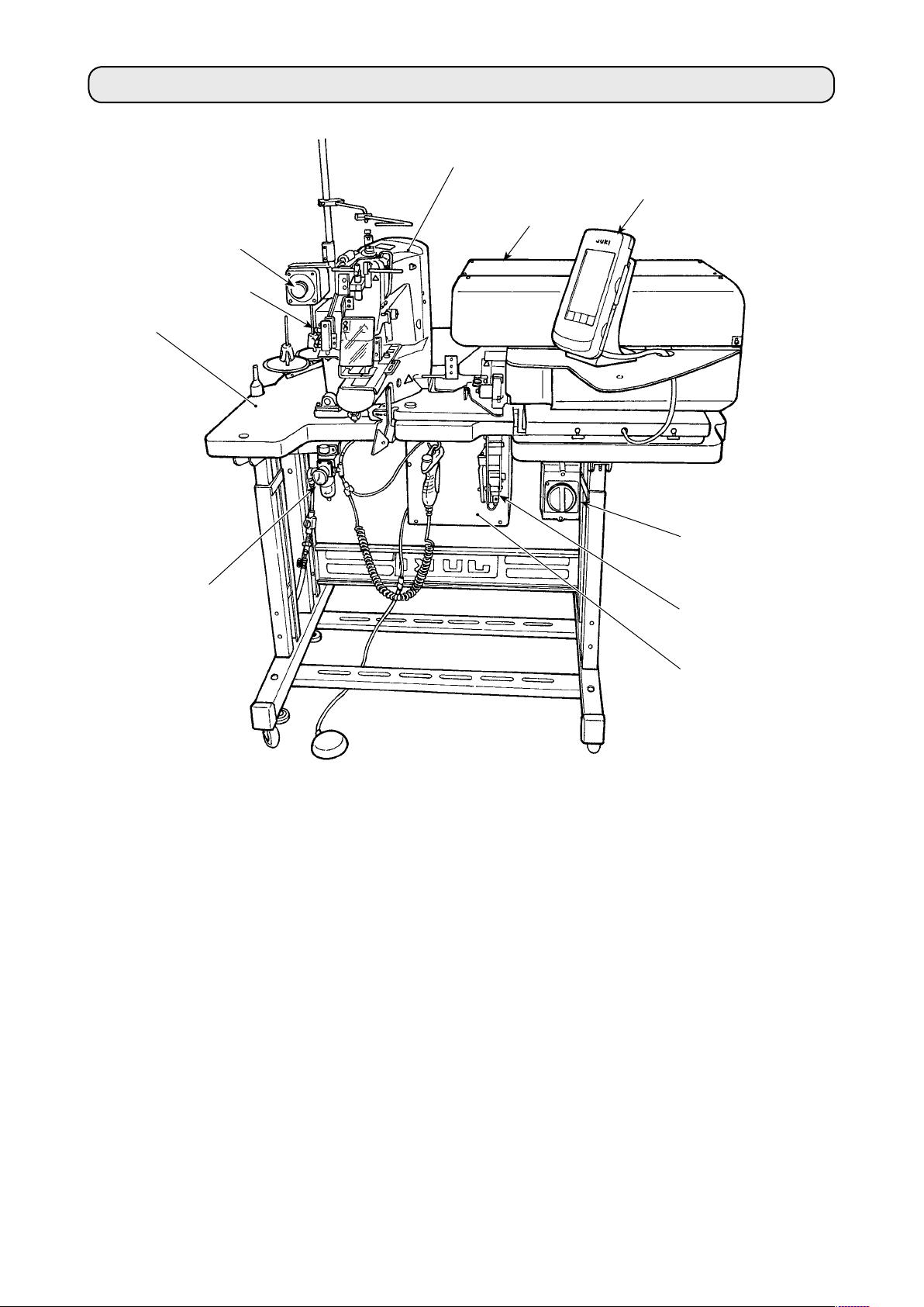
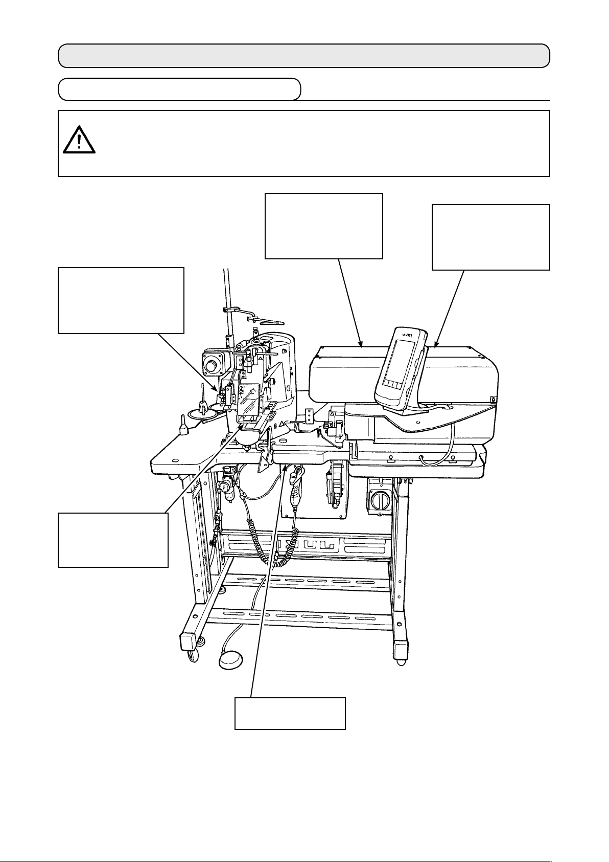
1. Conguration
H
C
A
E
G
B
D
This machine consists of the following nine sections:
Mechan
A
Belt loop feeder un
B
Belt loop tens
C
Pneumat
D
Sew
E
Control dev
F
Operat
G
Emergency stop sw
H
Belt-loop feed
I
Power sw
J
ical section of the main body structure (table stand, table, covers, start switch, etc.)
it (belt loop draw-out device, belt loop drawing device, etc)
ion releasing unit
ic control equipment section (pneumatic equipment, pneumatic piping, etc.)
ing machine section
ice
ion panel
itch
ing unit (optional)
itch
J
I
F
The machine is able to automatically sew desired belt-loops only by operating the start switch after
having placed a material (garment body) at the predetermined position on the machine.
When you press emergency stop switch
, the power to the dev
H
– 2 –
ices are turned OFF to stop them.
2. Specications
2-1. Mechanical specications
1
Sewing machine in use
2 Sewing speed Max. number of revolutions 2,500 sti/min (adjustable range: 400 to 2,500 sti/min)
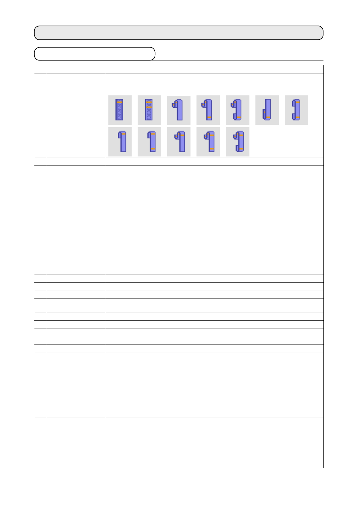
3 Belt-loop shape
4 Belt-loop width 8 to 20 mm
5 Standard sewing
pattern
6 Lift of the work clamp
foot of sewing machine
7 Needle bar stroke 45.7 mm (for 1903A)
8 Needle ORGAN needle DP x 17 #14 (Standard)
9 Hook in use Semi-rotary standard hook (x1.0)
10 Thread Spun #50 (recommended) Filament #50
11 Safety feature The machine automatically stops in the case a belt-loop clamping fault or thread
12 Lubrication oil JUKI New Defrix Oil No.2
13 Air pressure used 0.5 MPa
14 Air consumption 10 dm³ (ANR)/min or less
15 Dimensions W: 1,200 mm L: 850 mm H: 1,210 mm
16 Weight 205.5 Kg
17 Noise
18 Laser marking Class 2 laser product
LK-1961/AB H (exclusive intermediate machine head AB-1351 based on LK-1900A SS)
The stitching pitch has to be set at 3.2 mm or less. (Stitching pitch is input in increments
of 100 sti/min.)
* Linear bartacking (exclusive pattern for AB-1351)
Pattern No. selection method (from among 12-stitch, 15-stitch, 21-stitch, 28-stitch,
36-stitch and 41-stitch) is adopted. The widthwise pattern size is input on the operation
panel. The lengthwise pattern size is restricted to the 0 mm, and the widthwise one is
restricted to the range from 6 mm to 23 mm.
increments of 0.1 mm.)
* Zigzag bartacking (exclusive pattern for AB-1351)
Pattern No. selection method (from among 28-stitch, 36-stitch, 42-stitch, 56-stitch and
64-stitch) is adopted. The widthwise and lengthwise pattern sizes are input on the
operation panel. The lengthwise pattern size is restricted to the range from 1 mm to 3.2
mm, and the widthwise one is restricted to the range from 6 to 23 mm. (The lengthwise/
widthwise pattern size is input in increments of 0.1 mm.)
The distance from the top surface of the throat plate to the undersurface of the work
clamp foot is 20 mm.
breakage is detected.
(The lengthwise pattern size is input in
Declaration
- Equivalent continuous emission sound pressure level (LpA) at the workstation :
A-weighted value of 82.0 dB; (Includes KpA = 2.5 dB); according to ISO 10821- C.6.3
-ISO 11204 GR2 at 2,500 sti/min for the sewing cycle, 5.5s ON. (Pattern: No.4, 21
Stitches, Max Speed)
- Sound power level (LWA) ;
A-weighted value of 85.0 dB; (Includes KWA = 2.5 dB); according to ISO 10821- C.6.3
-ISO 3744 GR2 at 2,500 sti/min for the sewing cycle, 5.5s ON. (Pattern: No.4, 21
Stitches, Max Speed)
Maximum output: 1.0mW
Wave length: 650nm
Safety standard
JIS C 6802:2005
IEC60825-1+A2:2007
– 3 –
2-2. Electrical specications
1 Number of patterns that
can be stored in memory
2 Number of cycles that can
be stored
3 Input power source S
4 Power consumpt
in memory
ion 3-phase, 200 V type: 250 VA (instantaneous maximum power consumption: 450 VA)
99 patterns can be set.
Number of programs: 20
For each program, as many as 30 belt-loops can be set.
ingle-phase 200 – 240 VAC, 50/60Hz
3-phase, 200 - 240 VAC, 50/60 Hz (switchable to single-phase 100 - 120 V)
Supply voltage uctuation: Rated voltage ± 10 % or less
Adaptable to 380/400/415 VAC with the addition of an optional transformer.
*
Single-phase, 220 V type: 280 VA (instantaneous maximum power consumption: 670 VA)
* Average power when the machine sews 4000 belt-loops in eight hours under No. 4
sewing mode.
2-3. Sewing shape of belt-loops
B
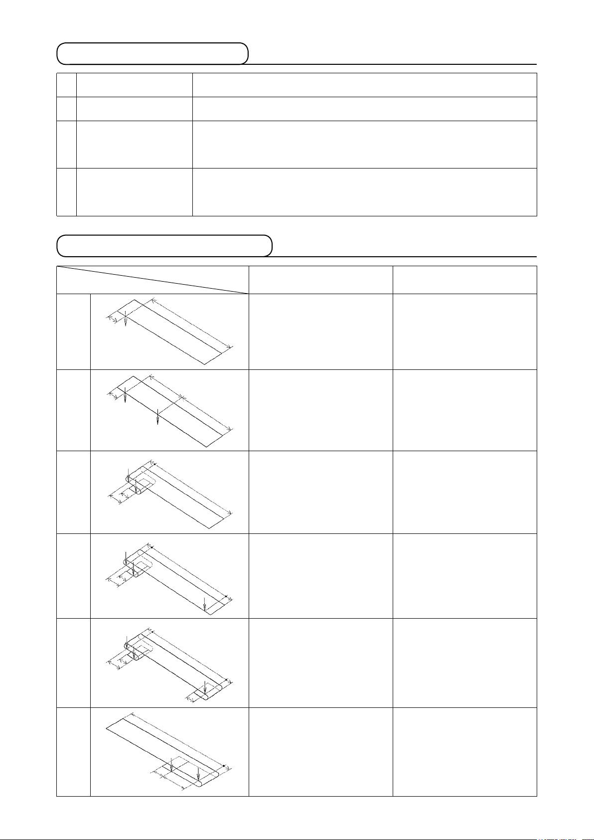
No.1
A
Work clamp foot for linear
bartacking
A = 4 mm * (-10 to 19)
B = 59 to 99 mm
Work clamp foot for zigzag
bartacking
A = 6 mm * (-9 to 21)
B = 59 to 99 mm
No.2
No.3
No.4
No.5
B
A
D
A
C
D
A
C
D
A
C
C
B
B
B
F
A = 4 mm * (-10 to 19)
B = 15 to 30 mm
C = 45 to 99 mm
A = 4 mm * (-10 to 19)
B = 45 to 109 mm
C = 5 to 11 mm
D = (2) mm
A = 4 mm * (-10 to 19)
B = 30 to 50 mm
C = 5 to 11 mm
D = 5 to 30 mm
E
E = 6 mm * (-14 to 16)
A = 4 mm * (-10 to 19)
B = 30 to 61 mm
C = 5 to 11 mm
D = 2 to 8 mm
E
E = 2.5 mm * (-2.5 to 7.5)
F = 10 mm * (0 to 20)
A = 6 mm * (-9 to 21)
B = 15 to 30 mm
C = 45 to 99 mm
A = 6 mm * (-9 to 21)
B = 45 to 109 mm
C = 5 to 11 mm
D = (2) mm
A = 6 mm * (-9 to 21)
B = 30 to 50 mm
C = 5 to 11 mm
D = 5 to 30 mm
E = 12 mm * (-12 to 22)
A = 6 mm * (-9 to 21)
B = 30 to 61 mm
C = 5 to 11 mm
D = 2 to 8 mm
E = 4 mm * (-1 to 9)
F = 10 mm * (0 to 20)
No.6
A = 4 mm * (-16 to 19)
B
A
C
B = 45 to 99 mm
C = 15 to 30 mm
D = 2.5 mm * (-2.5 to 7.5)
D
A = 6 mm * (-9 to 21)
B = 45 to 99 mm
C = 15 to 30 mm
D = 4 mm * (-1 to 9)
– 4 –
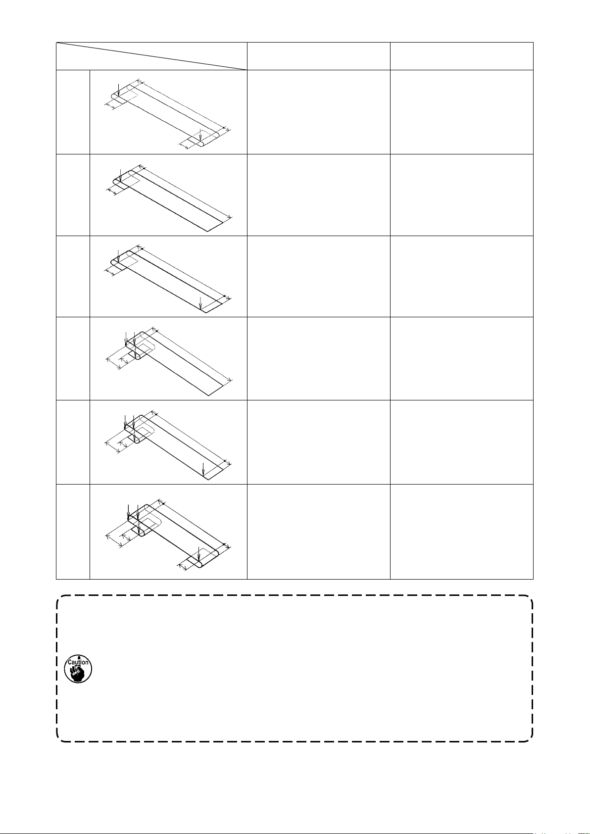
No.7
Work clamp foot for linear
bartacking
D
B
A
F
A = 10 mm * (0 to 1
B = 30 to 63 mm
D = 4 mm * (0 to 10)
E = 4 mm * (0 to 10)
E
F = 10 mm * (0 to 20)
Loosening amount = 0 to 20 mm
5)
Work clamp foot for zigzag
bartacking
A = 10 mm * (0 to 1
B = 30 to 63 mm
D = 3 mm * (0 to 10)
E = 3 mm * (0 to 10)
F = 10 mm * (0 to 20)
Loosening amount = 0 to 20 mm
5)
No.8
No.9
No.10
No.11
D
A
D
A
D
A
C
D
A
C
B
B
B
B
A = 10 mm * (0 to 1
B = 49 to 109 mm
D = 4 mm * (0 to 10)
A = 10 mm * (0 to 1
B = 30 to 60 mm
D = 4 mm * (0 to 10)
E = 6 mm * (-14 to 16)
E
Loosening amount = 5
A = 4 mm * (-10 to 19)
B = 45
to 109 mm
C = 5 to 11 mm
D = 4 mm * (0 to 4)
A = 4 mm * (-10 to 19)
B = 30 to
C = 5 to 11 mm
D = 4 mm * (0 to 4)
E
E = 6 mm * (-14 to 16)
Loosening amount = 5 to 30 mm
5
0 mm
5)
5)
to 30 mm
A = 10 mm * (0 to 1
B = 45 to 109 mm
D = 3 mm * (0 to 10)
A = 10 mm * (0 to 15)
B = 30 to 60 mm
D = 3 mm * (0 to 10)
E = 12 mm * (-12 to 22)
Loosening amount = 5 to 30 mm
A = 6 mm * (-9 to 21)
B = 45 to 109 mm
C = 5 to 11 mm
D = 3 mm * (0 to 4)
A = 6 mm * (-9 to 21)
B = 30 to 50 mm
C = 5 to 11 mm
D = 3 mm * (0 to 4)
E = 12 mm * (-12 to 22)
Loosening amount = 5 to 30 mm
5)
No.12
D
B
A
C
F
A = 4 mm * (-10 to 19)
B = 30 to
C = 5 to 11 mm
D = 4 mm * (0 to 4)
E
E = 2.5 mm * (-2.5 to 7.5)
F = 10 mm * (0 to 20)
Loosening amount = 4 to 16 mm
6 mm
5
A = 6 mm * (-9 to 21)
B = 30 to 56 mm
C = 5 to 11 mm
D = 3 mm * (0 to 4)
E = 4 mm * (-1 to 9)
F = 10 mm * (0 to 20)
Loosening amount = 4 to 16 mm
1. The range of belt-loop feeding length (the entire length of a belt-loop shown on the
operation panel) is from 58 mm to 130 mm. If the belt-loop feeding length exceeding the
aforementioned range is set, an error will occur.
2. In the case "distance B + distance D" exceeds 66 mm for pattern No. 4 or No. 5, "dis-
tance B + loosening amount/2" exceeds 66 mm for pattern Nos. 7 and 12, or "distance B
+ loosening amount" exceeds 66 mm for pattern Nos. 9 and 11, an error will occur.
3. The dimensions of the belt loop sewing shape displayed on the operation panel are
only for reference. The dimensions vary according to the belt-loop material. Be sure to
adjust the settings of belt loop dimensions so that your desired nished dimensions
are achieved.
* Numerical values shown in parentheses are set values. They are not the nished dimen-
sions.
– 5 –
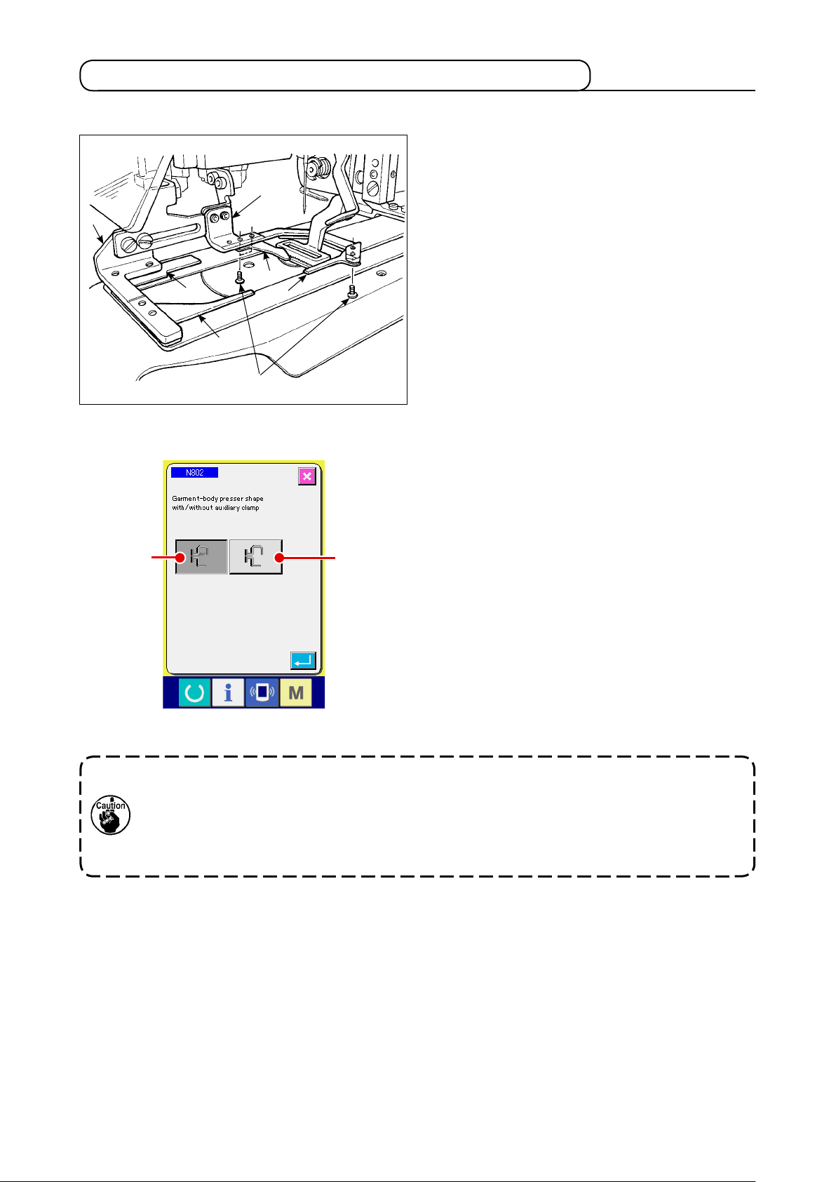
2-4. Garment body presser/work clamp foot specications
(1) Garment body presser
Garment body presser 1 and 2 for securing the
garment body is provided as standard with auxil-
ary clamps 3, 4, 5 and 6.
1
i
2
A
5
6
7
3
4
B
e aware that the auxiliary clamps 3 may be
B
r
equired to be removed according to the sewing
shape of the belt-loop.
In
the case of two kinds of sewing shapes; No. 2
and No. 6, auxiliary clamp
Loosen two screws 7
has to be removed.
3
and remove the auxiliary
clamps 3 from the garment body presser 1.
If you have changed the garment body presser,
set the machine setting N802 according to the
garment body presser actually being used.
itional clamp is provided
Add
A
itional clamp is not provided
Add
B
Refer to
→
"@-2-29. How to set the device"
, p.98
.
1. For belt loop shapes Nos. 5 and 7, auxiliary clamps 4 and 6 are damaged since they
are rubbed by the fork pin which rolls the belt loop. If the auxiliary clamps are heavily damaged, they can deform or break. It is necessary to periodically change auxiliary
clamps with new ones.
2. Install the auxiliary clamps at right angles to garment body pressers 1 and 2. Be sure
to check that the auxiliary clamps do not interfere with other parts.
– 6 –
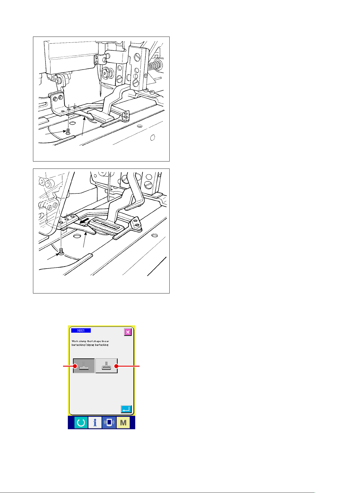
(2) Work clamp foot of the sewing machine
The work clamp foot of the sewing machine for linear bartacking is mounted as standard.
It is used when liner bartacking is used for sewing
various kinds of belt loops.
7
7
3
Work clamp foot of the sewing
machine for linear bartacking
3
Work clamp foot of the sewing
machine for zigzag bartacking
Be aware that, to carry out zigzag bartacking, the
currently installed work clamp foot and the feed
plate have to be replaced with those for zigzag
bartacking, and zigzag bartacking has to be set on
the operation panel.
In addition, when the work clamp foot for zigzag
bartacking is installed, auxiliary clamp
e re-positioned accordingly by loosening two
b
has to
3
screws 7 as shown in the gure at the left. (Refer to
clamp foot specications", p.6.
"!-2-4 (1) Garment body presser/work
)
A
B
If you have changed the work clamp foot of the
sewing machine, set the machine setting N801
according to the work clamp foot actually being
used.
ing frame for linear bartacking
Feed
A
initial value)
(
ing frame for zigzag bartacking
Feed
B
"@-2-29. How to set the device"
– 7 –
Refer to
→
, p.98
.
3. Installation
3-1. Removing the packing materials
CAUTION
:
1. If you lift the machine, do not hold any of the devices or the mechanical section of the
sewing machine but hold the table.
2. When you move the machine, the machine head xation bolt must be attached to the
machine. Be sure to carefully keep the machine head xation bolt.
Remove the cover.
Remove the string and
packing material which are
used to x the belt loop
tension releasing unit.
Remove the cover.
Remove the string and
packing material which
are used to x the belt
loop drawing unit.
Remove the upper
section cover. Remove
the string and packing
material which are used
to x the XY unit.
Remove the adhesive
tape which is used to
x the garment body
presser.
Remove the machine
head xation bolt.
– 8 –

3-2. Fixing the machine
3
CAUTION
1. In order to protect against accidents causing personal injury or death, move the
machine to a level and stable place and secure it by lowering adjuster bolts 2 (at four
locations) placed at the side of casters 1.
2. When adjusting the leg height of the sewing machine, the leg xing bolts 3 need to be
loosened to move the leg up or down. When the xing bolts have been loosened, there
is a danger for the legs to suddenly drop down. Therefore, be careful when loosening
the bolts.
:
1
2
3-3. Connecting the air coupler
4
3
1
Connect air coupler 1
an accessory to air hose 2.
coupler to coupler 3 on the ma
1. After having connected coupler 1
with air cock 4 closed, carefully
open air cock 4 to supply air.
2. Check to be sure that the pressure
gauge of the regulator indicates 0.5
MPa.
supplied with the unit as
Then, connect the air
in body side.
2
– 9 –
3-4. Connecting the power plug
CAUTION
In order to protect against accidents caused by a ground fault or dielectric voltage, be
sure to have the adequate power plug mounted by a person who has electrical expertise. It
is also important to connect the power plug to the grounded receptacle.
:
The method to connect the product to the power source differs by the product specications. Be sure to
connect the product to the power source according to the power specications.
For the single-phase, 200 - 240 V type product
1
Connect the sky-blue/brown wire of the power cord to the supply terminal (200 - 240 VAC) and the
yellow/green one to the earth terminal respectively.
For the 3-phase, 200 - 240 V type product
2
Connect the red/wh
ite/black wire of the power cord to the supply terminal (200 - 240 VAC) and the
yellow/green one to the earth terminal respectively.
For the product prov
3
ided with an high-voltage optional transformer
Connect the black wires (three) of the power cord to the supply terminal (380 - 415 VAC) and the
yellow/green wire to the earth terminal respectively. The product can be connected to 380/400/415
V power terminals according to the setting of the input tap of the transformer. (Standard setting at
the time of shipment: 380 V)
In the case the single-phase, 200 - 240 V type product is modied to the 3-phase, 380/400/415 V
4
type one
Opt
ional parts are required.
• High-voltage optional transformer Parts No.: 40005422
• Power cord Parts No.: 40070548
In the case of the 3-phase, 380/400/415 V power supply, this product is operated under the
single-phase connection state.
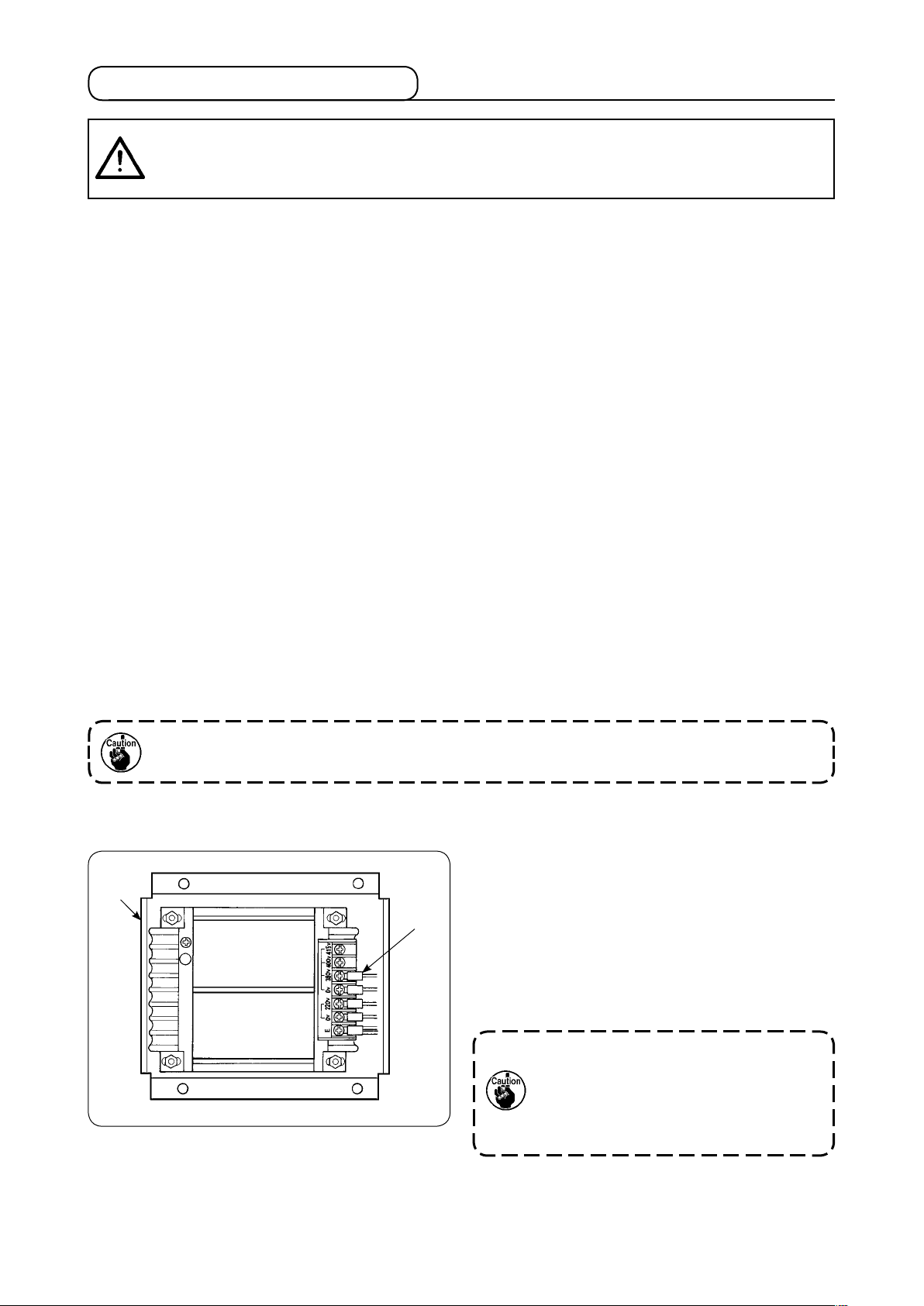
[Precaution to be taken when changing the power of the high-voltage optional transformer]
To use high-voltage optional transformer 1
the input voltage of 400 V or 415 V, you need to
1
2
replace input power cord
tional transformer 1
power input cord 2
(brown) which is connected to
of high-voltage op-
2
correspondingly. Change
the 380 V power terminal with the one for 400 V or
415 V connection.
In order to protect against accidents,
the aforementioned work should be
carried out after having left the sewing
machine for 5 minutes or more with
the power switch turned OFF and the
cord removed.
with
High-voltage optional transformer 1 i
the side face of the control box.
– 10 –
s placed on

CAUTION
:
To protect against accidents such as an electric shock, be sure to turn the power off and
remove the power cord from the receptacle before the following work.
[How to install the high-voltage optional transformer (part number: 40090561)]
1) Loosen four screws on the front side of emeritch 1. Open the sw
1
gency stop sw
Remove the power cord (brown, sky blue,
yellow/green wires) from the secondary side
(on the side 2
is printed).
2) Connect the power cord to the optional trans-
former. Connect the power cord (40005423:
Three-w
ire cord) supplied with the unit to the
optional transformer.
Brown wire → 380/400/415 V (accord
2
3
the power specications)
Blue wire → 0 V (next to the 380 V)
ellow/green wire →
Y
E (on the ring terminal side)
Connect the cord on the control box side (the
(Inner part of the emergency stop switch)
cord which has been removed in Step 1).
Brown wire → 220 V
Sky blue wire → (next to the E)
Yellow/green wire → E
itch box.
ing to
2−1 2−2 2−3
(Wiring of the optional transformer)
Su
cord
On the control box
side
C
E 0V 220V 0V 380V 400V 415V
ommon (ground)
E
econdary
S
side
(indicated
as 2)
pplied po w e r
3) Install optional transformer on the side face
of control box 2. Refer to "HIGH VOLTAGE
TRANSFORMER SETUP INSTRUCTION
(40005426)" for connect
ing procedure.
4) Connect the power cord supplied with the unit
to emergency stop switch 1.
Brown wire → 2-1
Sky blue wire → 2-2
Yellow/green wire → E
(Brown and sky blue wires respectively have a
fork terminal.)
5) Re-tighten the four screws of emergency switch
Take care not to leave a gap in the switch.
.
1
6) Change the cord on the plug side of the
power switch. (40070548: 4-wire cord)
Open the power switch. Remove connection
cords on the side of L1, L2 and L3.
Black 1, 2 and 3 wires (on the forked terminal
side) → L1, L2 and L3
in the power switch
Yellow/green wire → Ground (in the power switch)
* Discard the cord mounted your machine at
the time of delivery.
– 11 –
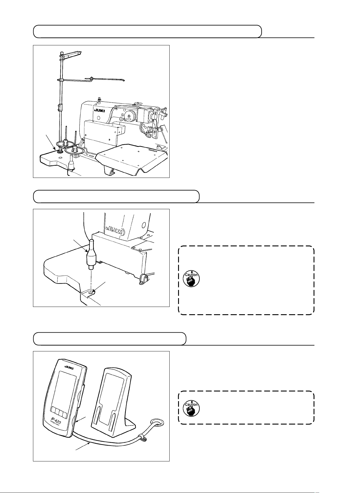
3-5. Assembling the thread stand and installing on the machine
Insert the thread stand in the hole in table 1 and
x by fastening a washer and a nut placed on the
top and unders
1
ide of table.
3-6. Installing the machine head support bar
1
2
3-7. Installing the operation panel IP-420
Securely mount machine head support bar included in the accessories supplied with the unit.
i
Drive machine head support bar
n hole 2 in
1
the machine table.
When tilting the sewing machine, tilt
the sewing machine slowly so that no
excessive force will be applied to the
head support bar.
And when returning the sewing machine back to its original position,
be careful not to have your hand get
caught between the base and the sewing machine bed.
Open the cover on right side face 2 section of
the IP-420 and connect the connector of cable 1
ich is secured with adhesive tape on the upper
wh
right face of the table to the IP-420.
1
2
To protect the operation panel IP-420
fro m ma lfuncti onin g du e to sta tic
electricity, mount the operation panel
on the operation panel base.
– 12 –
3-8. Installing the auxiliary table
1
2
3
4
2
Loosen the buttery nut on the top surface of the table. Install the auxiliary table for attaching straps left
ight 2 in place.
and r
1
Install it at such a location where a clearance of 3 mm is provided between the throat plate 3 and each
iliary table.
aux
Remove the start switch connector provided as standard at the time of delivery. Then, insert start switch
connector 4 wh
ich has been mounted on auxiliary table right 2.
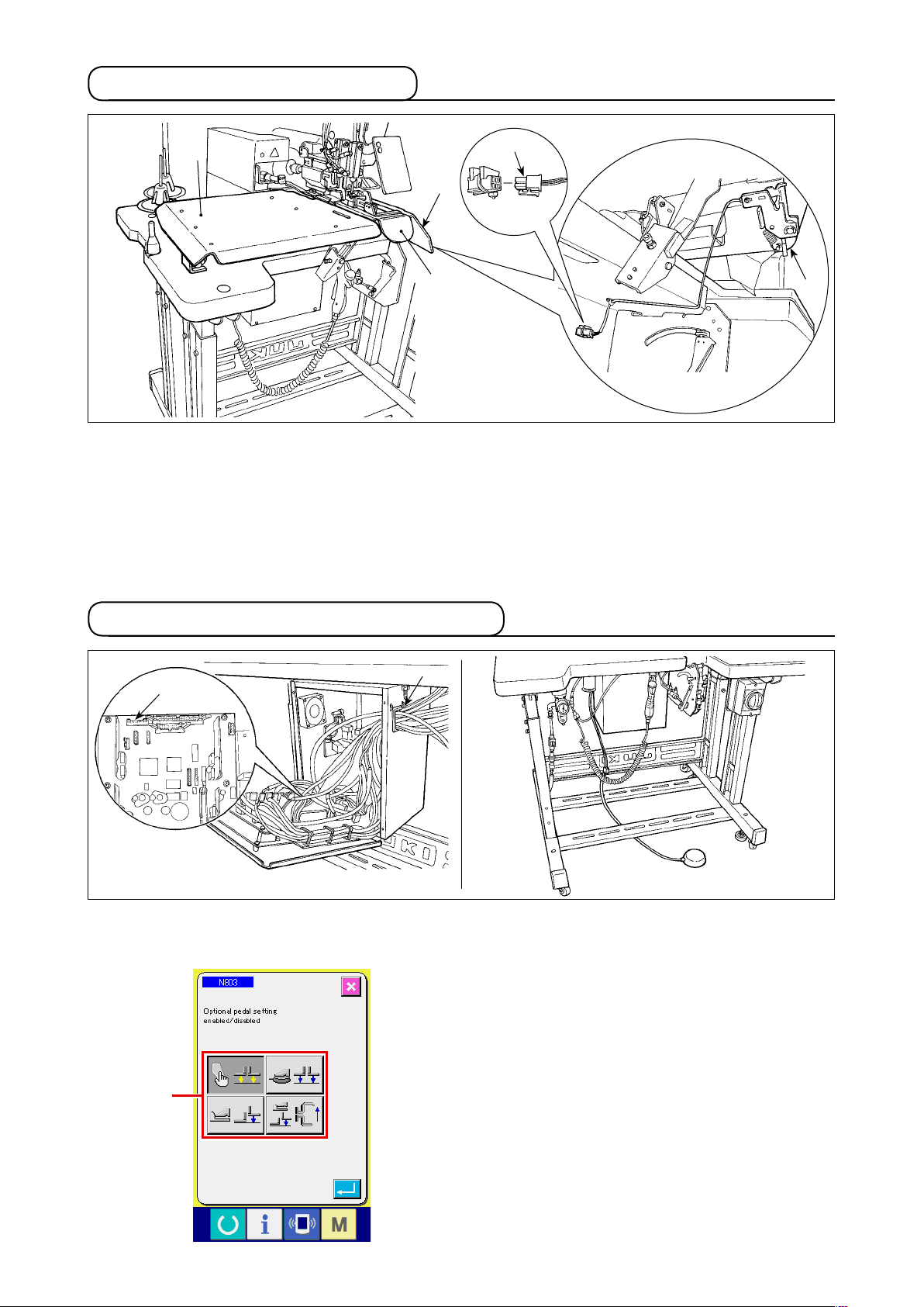
3-9. Installing the manual pedal (optional)
2
1
Open the cover of the control box. Insert connector CN88 of the manual pedal into connector 1 CN51
in the control box via the junction cable (40073659). Pass the cable through 2
Change the setting to “with optional pedal” on the
machine setting N803 A.
Refer to
→
"@-2-29. How to set the device"
in the control box.
, p.98
.
A
– 13 –

3-10. Installing the belt loop feeding unit (optional)
1
Mount the belt loop feeding unit on the table and
x it by tightening screws 1
the table.
exclusive junction cable 2
ing unit side.
3
2
Connect
board located behind the main body.
Connect junction cable
feed
In the case the belt loop feeding unit
is to be installed on the machine, the
belt loop guide parts installed as standard at the time of delivery have to be
removed.
on the underside of
to the junction
to connector 3 on the
2
4
5
6
Pull out plug 5
nect air tube 6
from air coupling 4. Then, con-
on the belt loop feeding unit side
to air coupling 4.
Change the setting to “with belt loop feeding auxiliary unit” on the machine setting N806 A.
A
– 14 –
Refer to
→
"@-2-29. How to set the device"
, p.98
.

3-11. Installing the additional marking light (optional)
Insert exclusive junction cable 1 into connector
of the junction board located behind the
2
1
CN85 2
main body.
(There are three CN85 connectors including the
one used as standard. You may insert the junction
cable any of the three connectors.)
– 15 –
4. Preparation of the sewing machine
4-1. Lubrication
CAUTION
Turn OFF the power before starting the work so as to prevent accidents caused by abrupt
start of the sewing machine.
:
Check that the place between lower line B and upper line A is lled with oil. Fill there with oil using
oiler supplied with the machine as accessories
the
when oil is short.
* The oil tank which is lled with oil is only for lubri-
ating to the hook portion.
c
It is possible to reduce the oil amount when the
number of rotation used is low and the oil amount
A
B
in the hook portion is excessive. (Refer to
Amount of oil supplied to the hook", p.134
1. Do not lubricate to the places other
than the oil tank and the hook of
Caution 2 below. Trouble of components will be caused.
2. When using the sewing machine for
the rst time or after an extended
period of disuse, use the machine
after lubricating a small amount of
oil to the hook portion. (Refer to
"#-1-3. Adjusting the needle-tohook relation”, p.131.)
"#-1-10.
.)
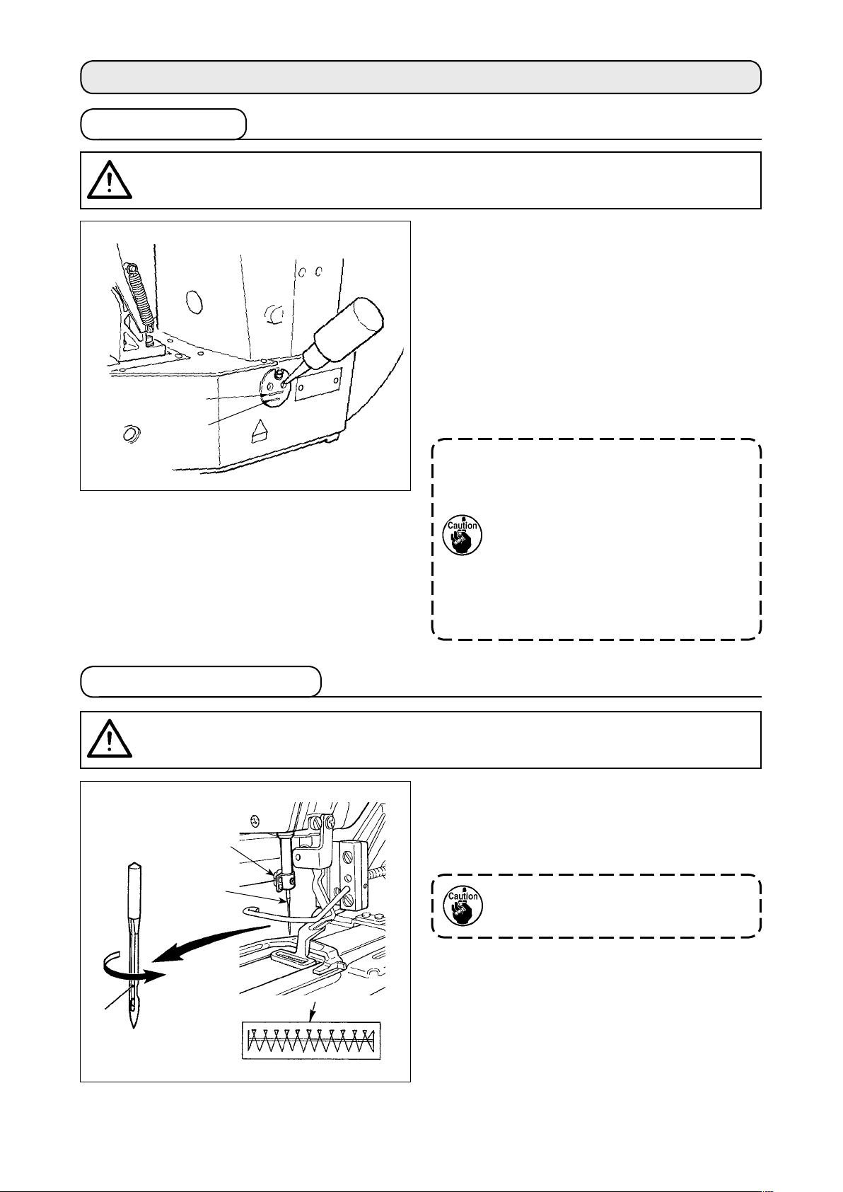
4-2. Attaching the needle
CAUTION
Turn OFF the power before starting the work so as to prevent accidents caused by abrupt
start of the sewing machine.
B
3
:
1
2
A
Loosen setscrew 1 and hold needle 2
long groove facing 3
toward you. Then fully insert
with the
it into the hole in the needle bar, and tighten setscrew 1.
If the seam shown in A is produced,
adjust the needle orientation slightly in
direction B.
– 16 –

4-3. Threading the machine head
CAUTION
Turn OFF the power before starting the work so as to prevent accidents caused by abrupt
start of the sewing machine.
:
1
2
For synthetic thread
Draw the thread after having threaded the needle so that approximately 4 cm thread trails from the needle eyelet.
When you use silicon oil, pass the thread through silicon-thread thread guide 1.
thread thread guide is an optional part.)
(Silicon-
4-4. Installing and removing the bobbin case
CAUTION
Turn OFF the power before starting the work so as to prevent accidents caused by abrupt
start of the sewing machine.
:
1) Open hook cover 1.
3
2) Raise latch 3 of bobb
in case 2, and remove
the bobbin case.
3) When installing the bobbin case, fully insert it
into the hook shaft, and close the latch.
2
1
If it is not fully inserted, bobbin case
may slip off during sewing.
2
– 17 –
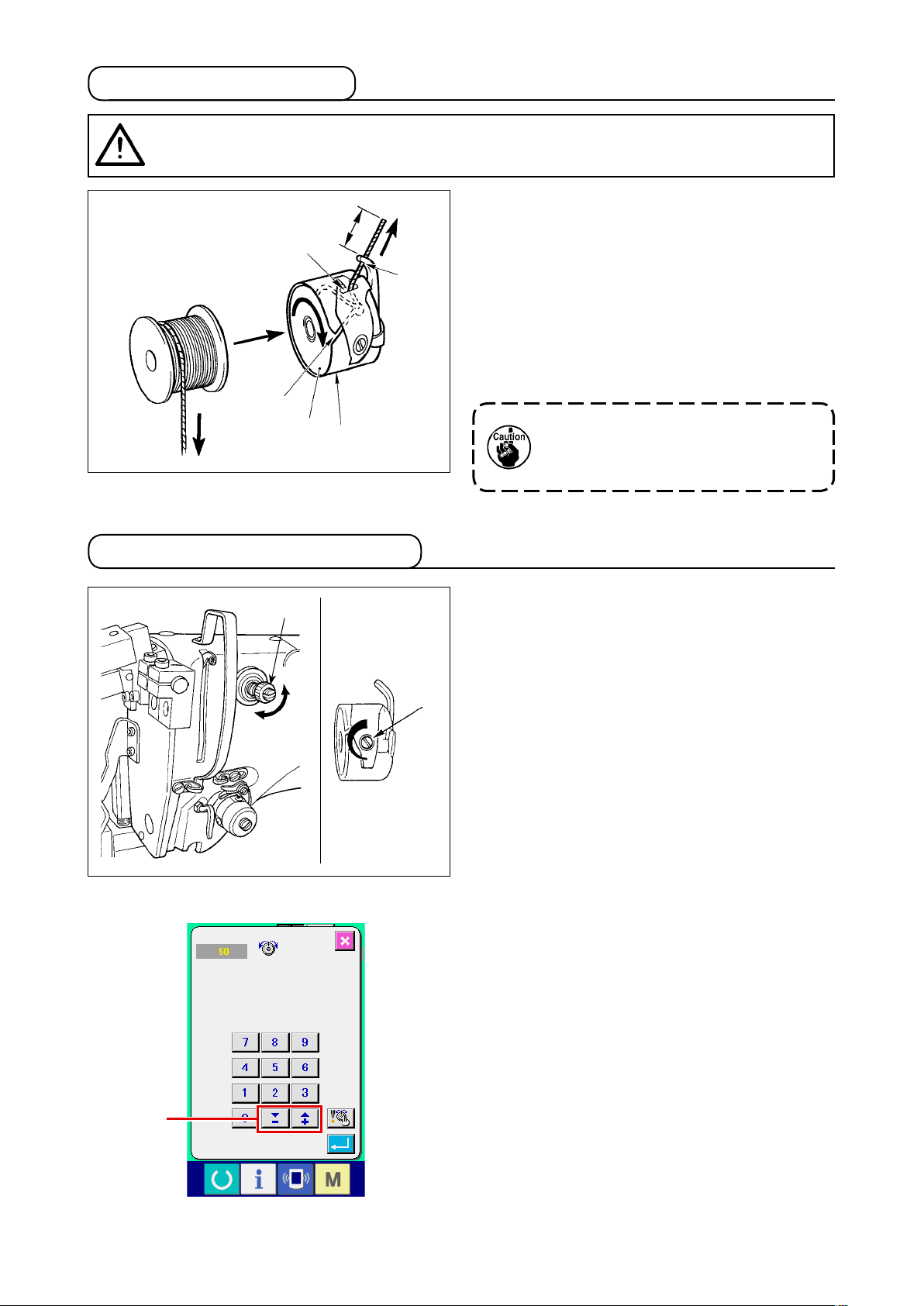
4-5. Installing the bobbin
CAUTION
Turn OFF the power before starting the work so as to prevent accidents caused by abrupt
start of the sewing machine.
:
2.5 cm
4
3
1
2
4-6. Adjusting the thread tension
5
1) Set the bobbin 1 into bobbin case 2 in the
direction shown in the gure.
Pass the thread through thread slit 3 of bob-
2)
in case 2, and pull the thread as
b
it is. By so
doing, the thread will pass under the tension
spring and be pulled out from thread hole
3)
Pass the thread through thread hole 5 of the
horn sect
ion, and pull out the thread by 2.5
4
cm from the thread hole.
If the bobbin is installed in the bobbin
case orienting the reverse direction,
the bobbin thread pulling out will result in an inconsistent state.
.
1
Long
Short
Adjusting the needle thread tension
2
If thread tension controller No. 1 1 is
turned
clockwise, the length of remaining thread on the
needle after thread trimming will be shorter. If it is
turned counterclockwise, the length will be longer.
Shorten the length to an extent that the thread is
not slipped off.
(The standard length of thread remaining on the
needle is approximately 4 cm.)
The needle thread tension is adjustable on the op
erat
ion panel. The bobbin thread tension is adjust-
able by means of 2.
The needle thread tension to be applied to the
bartacking sections can be set by means of thread
tension setting button
on the operat
A
ion panel.
-
A
– 18 –

4-7. Adjusting the thread take-up spring
1
4
3
2
The standard stroke of thread take-up spring 1 is
8 to 10 mm, and the pressure at the start is 0.1 to
0.3N.
1)
Adjusting the stroke
Loosen setscrew
, and turn thread tens
2
ion
asm. 3.
urning it clockwise will increase the moving
T
amount and the thread drawing amount will
increase.
2) Adjusting the pressure
To change the pressure of the thread take-
up spring, insert a thin screwdriver into the
slot of thread tension post
while screw 2
4
is tightened, and turn it. Turning it clockwise
will increase the pressure of the thread takeup spring. Turning it counterclockwise will
decrease the pressure.
4-8. Example of the thread tension
When using the sewing machine for the rst time, adjust the thread tension referring to the table below.
Thread Material
Polyester spun thread #50 Wool 50 to 55 10mm [13mm] 0.2N
Polyester lament thread #50 Wool 30 to 35 10mm [13mm] 0.1N
Needle thread
tens
ion setting
Thread take-up spring moving
amount [Thread drawing amount]
Strength
– 19 –
5. Operating the sewing machine
5-1. Emergency stop switch
(1) Method for operating the emergency stop switch
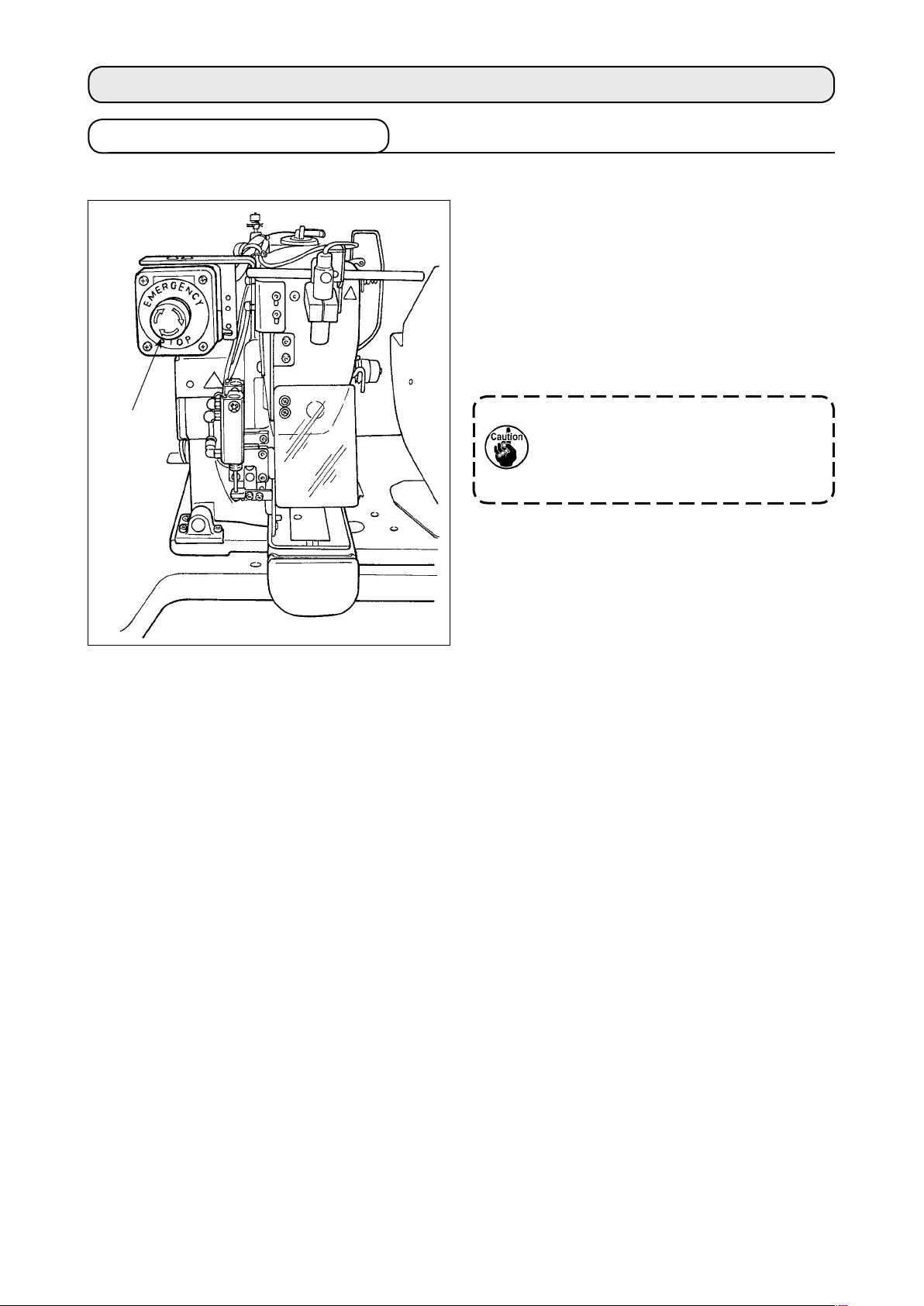
Emergency stop switch 1 is mounted on the upper left section of the sewing machine head.
Emergency stop switch
ly pressing in the red button. It is turned OFF by
turning it counterclockwise.
If you turn ON emergency stop switch
machine is in operation, the power is turned OFF
to cause the machine to stop operation.
i
s turned ON by strong-
1
while the
1
1
To turn OFF the power for any purpose other than
an emergency stop, operate the power sw
If yo u t urn OFF em ergency st o p
switch 1 with the power switch remained ON, the power is re-turned
ON. Take care of abrupt re-turn ON of
the power.
itch.
(2) Precautions with the emergency stop switch
When emergency stop switch 1
ON/OFF the power switch. The work clamp foot of the sewing machine may depress the loop clamp or
the belt loop loosening rod according to the operation timing of emergency stop switch
nomenon
the sewing machine to move it so as to avoid interference. Then, re-turn ON the power to the sewing
machine.
occurs, turn OFF the power to the sewing machine and manually lift the work clamp foot of
stays ON, the sewing machine cannot be powered up even if you turn
.
If this phe-
1
– 20 –

5-2. Winding a bobbin
(1) To wind a bobbin while the sewing machine is performing sewing
Thread the bobbin winder and wind the bobbin
thread onto the bobbin as illustrated in the gure.
(2) To wind a bobbin independently
A
In the case you only want to carry out bobbin winding
on the sewing machine, unthread the needle and remove the bobbin from the hook.
Displaying the bobbin thread winding screen
1
Press bobb
in winding button A on the belt loop data
input screen (blue), and the bobbin winding screen appears on
the screen.
S
tarting bobbin winding
2
B
Press the start switch, and the sewing machine rotates to start
bobbin winding.
topping the sewing machine
S
3
Press stop button
B, and the sew
ing machine stops and
returns to the normal mode. If you press the start switch again
during bobbin winding, the sewing machine stops under the
bobbin winding mode. If you press the start switch again in this
state, the sewing machine re-starts bobbin winding. Use this
operating procedure when you want to wind thread on two or
more bobbins.
The bobbin winding will not start immediately after
turning the power ON. To activate the bobbin winding
function, set a pattern number or the like first, then
press the set ready key to invoke the sewing
screen. In this state, the bobbin winding function is
enabled.
– 21 –
5-3. Thread clamp device
Trouble of sewing (slip-off of needle thread, stitch skipping, or stain of needle thread) at the time of highspeed start can be prevented with the thread clamp device.
The thread clamp device will operate when the thread clamp button has been selected
not operate when the thread clamp button has not been selected
.
, but it will
Changeover of ON/OFF motion is performed with
key. When the thread grasping device is in the
OFF state, the sewing machine is automatically set to the soft-start mode.
1. When memory switch is "1" (prohibited), the thread clamp does not work. Fur-
thermore, the thread clamp key
2. Memory switch, refer to "@-2-28. How to change the memory switch data”, p.93.
will not be displayed.
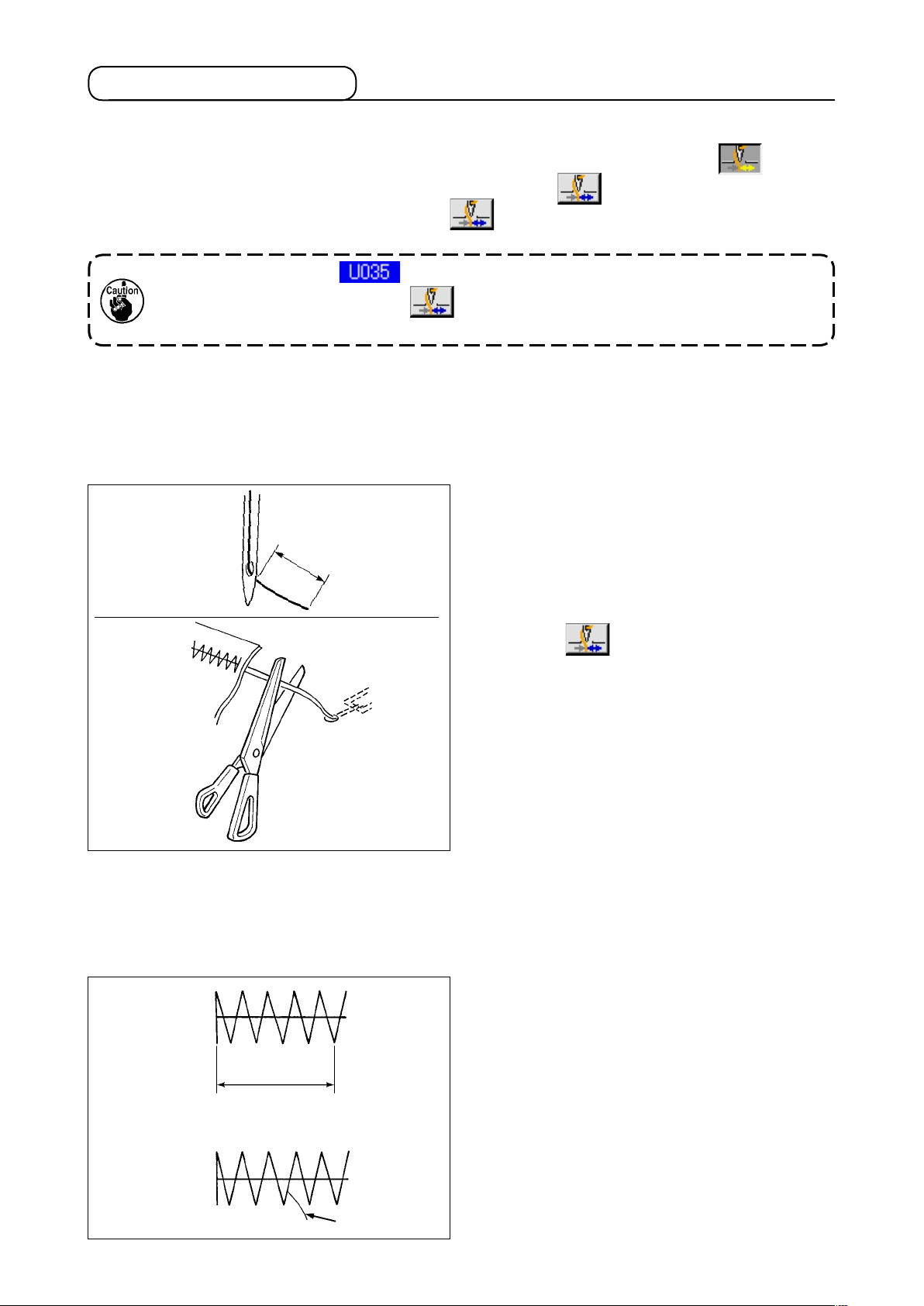
* Matters that demand special attention when using the needle thread clamp
(1) In case of with the needle thread clamp (motion), make shorter the length of needle thread remain-
ing on the needle at the sewing start for use. When the length of needle thread is lengthened,
needle thread on the wrong side of material is apt to protrude. In addition, when the length is
excessively lengthened, the end of needle thread held by the needle thread clamp may be rolled in
the seams.
In case of with the needle thread clamp, the
1)
33 to 36 mm
3)
1)
standard of the length of needle thread is 33
to 36 mm.
2)
When needle thread is long after replacing
thread or the like or sewing while holding nee
dle thread by hand, turn OFF the THREAD
CLAMP
3)
When the needle thread held with the thread
key.
clamp is rolled in the seams, do not draw the
material forcibly and cut the connecting needle
thread with the scissors or the like. The seams
are not damaged since it is the needle thread at
the sewing start.
-
(2) It is possible to adjust needle thread shorter by making the needle thread clamp work while holding
the stabilized sewing at the start of sewing and the gathering (bird's nest) of needle thread on the
wrong side of material can be lessened. However, for the pattern which the stitch length for neatly
rolling in needle thread is short, needle thread may protrude from the wrong side of material. Select
with/without thread clamp referring to the item below.
When the sewing length is short (less than ap-
(Right side)
proximately 10 mm), the end of needle thread may
protrude like beard even when adjusting needle
thread shorter.
10mm
(Wrong side)
N
eedle thread
– 22 –
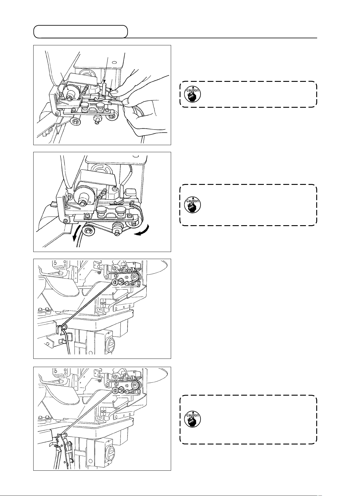
5-4. Placing a belt loop
3
2
1
Press down multi-layered part detecting bracket
and lever 1 of the gear of the loop draw-out
3
ice to put the belt loop into the guide until it is
dev
placed under gear 2.
When you route the belt loop under
the gear, insert it until it appears from
the belt loop cutting knife.
*
In the case the sewing machine is ON, when
multi-layered part detecting bracket 3 i
s pushed
up, the gear is rotated by the motor to feed the
belt loop.
Route the belt loop
in the direction of the arrow.
Finally, route the belt loop in the guide roller sec-
ion on the table to allow it to trail downward.
t
Position the belt loop below the guide
roller so as to prevent it from being
hitched or being applied with an excessive resistance at the time of belt
loop feeding.
In the case the optional belt loop feeding unit is to
be mounted on the sewing machine, route the belt
loop as illustrated in the gure at left.
The belt loop feeding unit is provided
with a capability of detecting two different errors; one is the case the belt
loop has knots and the other is the
case the belt loop cannot be fed due
to an excessive resistance.
– 23 –
5-5. Adjusting the belt loop tension
A
When you have changed the belt loop, you need to re-adjust the
belt loop tension without exceptions.
Press the belt loop tension button A on the sewing
screen.
more the belt loop tension is adjusted in a negative direc-
The
ion, the less the belt loop tension becomes. (The belt loop ten-
t
s
ion can be set and stored in memory on a sewing-pattern by
sewing-pattern basis.)
As a guide, adjust the belt loop tension so that the entire length
of the belt loop fed from the belt loop feeding section and
clamped at the belt loop clamping section is shorter than the
entire belt loop length displayed when selecting a sewing pat
tern by approx
imately 1 mm.
If the sewing machine is operated under a high belt
loop tension, the entire length of the belt loop fed
becomes shorter than required. In this case, problems such that the belt loop cannot be sewing at
the predetermined length or that the cut end of the
belt loop is not straight can occur. To prevent such
problems, adjust the belt loop tension adequately.
-
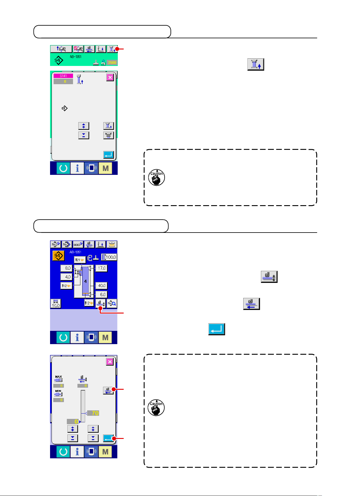
5-6. Setting the belt loop thickness
When you use a new belt loop, you need to set the belt loop
thickness without exceptions. If the belt loop has multi-layered
parts (splices), thickness of the multi-layered part has also to
be set.
Press belt loop
eration panel screen.
Route the belt loop to be used in the predetermined manner
and
A
B
C
fed as long as the feed key is held pressed. As long as you
keep the feed key held pressed, the belt loop is fed. Be sure to
press the enter button
normal-thickness part and multi-layered part of the belt loop un-
der the mult
1. If the belt loop thickness is smaller than the pre-
2. As a guide, the belt loop thickness is 1 to 1.8 mm.
thickness teaching button A on the op-
press belt loop feeding button
C after having passed both the
i-layered part detecting section.
determined value, the belt loop presence/absence
detector of the belt loop drawing device may
determine that the belt loop is absent even if the
belt loop is present. If the aforementioned error
occurs, operate the sewing machine with the belt
loop presence/absence detecting function disabled.
If the belt loop thickness exceeds the aforementioned range, the belt loop clamping section and
the work clamp foot of the sewing machine can
interfere with each other. To prevent this, be sure
to perform trial stitching in prior to conrm no
interference between them. Then, start sewing.
B. The belt loop is
– 24 –
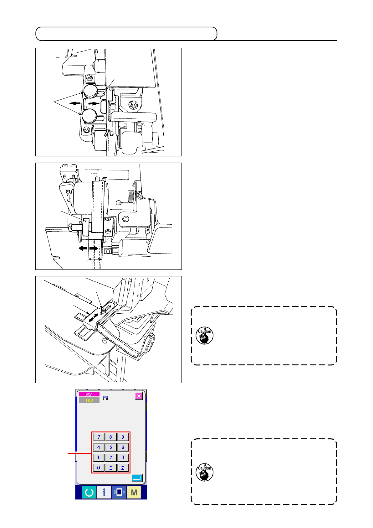
5-7. Method for changing the belt loop width
1) When you want to change the belt loop width,
1
Adjust so that the belt-loop passes through
2
Check that the top end of the belt loop gu
2) Adjust the position of guide 1 according to
1
loosen two screws 2 of belt loop gu
ide 1
to adjust the guide width to t the belt loop
idth.
w
the belt-loop guide smoothly with no exces
ive lateral space between the guide and the
s
belt loop, with guide
pressed lightly against
1
the belt loop.
ide
matches the belt loop width.
the belt loop width.
-
A
3
4
3) Loosen setscrew 4 of the belt loop clamp.
Adjust the position of loop clamp, upper 3
accord
ing to the belt loop width.
The width of the belt loop guide section and that of the belt loop clamping
section should be adjusted so that the
belt loop smoothly pass through and
that no widthwise play exists. If there
is an excessive widthwise play, the
belt loop attaching location can vary.
4) Enter a value of belt loop width into belt loop
width setting section
on the operat
A
ion
panel screen. At the same time, change the
dimensions of a seam for attaching a belt
loop. Refer to
belt loop length", p.39
ing the seam dimensions.
chang
If the bartacking width of which is extremely wider than the bartacking width
setting specified through the operation
panel is sewn, the garment-body presser
and the belt-loop clamp can interfere with
each other (error No. M596). If the alarm
is given, change the bartacking width setting to decrease the bartacking width.
"@-2-6. How to change the
for the method for
– 25 –
 Loading...