

Operation
Manual'
.
for
Model
61OO
Daisywheel
printer
.i:r
r!
{-
lAll
efforts
have been
made to ensure the accuracy
ol the contents of this
manual.
.'
t-ver,
should any
errors be detected,
JUKI wouid
greatly
appreciate
being in_
NOTICE:
All rights
reserved. Reproduction
of any
part
of this
manual in any form whatsoever
without
Juki express
written
p€rmission
is forbidden.
The contents
of this
manual are $rbiect to change
without notic€.
l.of
them.
can
assume no responsibility
tor any errors
in
this
notdthstanding. JUKI
Iuo
their consequencrs.
o copyright
1983 by TOKYO JUKI
Tokyo, Japan
INDUSTRIAL
CO., LTD.
FCC
COMPLIANCE
STATEMENT
FOR AMERICAN
USERS
This
equipment
generates
and uses radio
lrequency enetgy
and ifnot
installed and used
prop€.Iy,
that is, in stdct accordance
with
the manufacturcr's
instructions, may
cause
interference
to radio and television
reception.
[t
has
been
type tested and found
to
comply with
the limits for a
Class B computing
device in accordance
with the specifica-
tions in Subpart J
of Pa 15 of FCC
rules, which
are designed to
provide
reasonable
protection
against such interference
in a residential
installation. However,
there is no
guarantee
that interference will not
occur in a
pa
icular
installation.
U
this
equipment
does cause intederence
to radio or tQlevision
reception,
which can
be d€termined
by
tuming the equipment
off and on, the use!
is encouraged
to try to
correct the inter-
ference
by one or more of
the following
mea$$es:
Reorient
the receiving antenna.
Relocate the
computer with respect
to the receiver.
MoVe the computer
away from
the receiver.
Plug
the computer into
a diflerent outlet
so that
computer and receiver
are on
different branch chcuits-
If necessary,
the user should consult the
dealer or an experienced
radio/television
techni-
cian for additional
suggestions. The us€r may
find the followinS
boollet
pr€par€d
by the
Federal
Communications Commission helpful:
"How
to Identify
and Resolve RadiqTV
Interfercnce Problems".
This booklet is
available from the
U.S.
coveminent
hintins
Office, Washington, D.C.
20402, Stock No.
00+00G00345-4.
d
Settin$, Canridge
Ribbon . . . . . . . . ...............
6
Attaching a Oai3y
Whelto the Printer....... ........
7
Setting
Paper
bn
ttig 9fin'ier
.3'.
. . 1 ......8,
6.'l Lo.ding eEDet
gn theDtinter . . . . . . . .......
8
6,2
Fine
odiu.lhfit 6Fthc
printing po.ition
. . . : .c . . . . . . . . . . . . . . , . , . gl
6.3 corr€cting tho
poiition
of
papor
. . . . . . .., .
.
9-r
INTRODIJCTION
1.
General Oescription
2.
Spocific.tioni
Print
speed
Print wheel
Print wheel
life
Number
of characte$
per
line
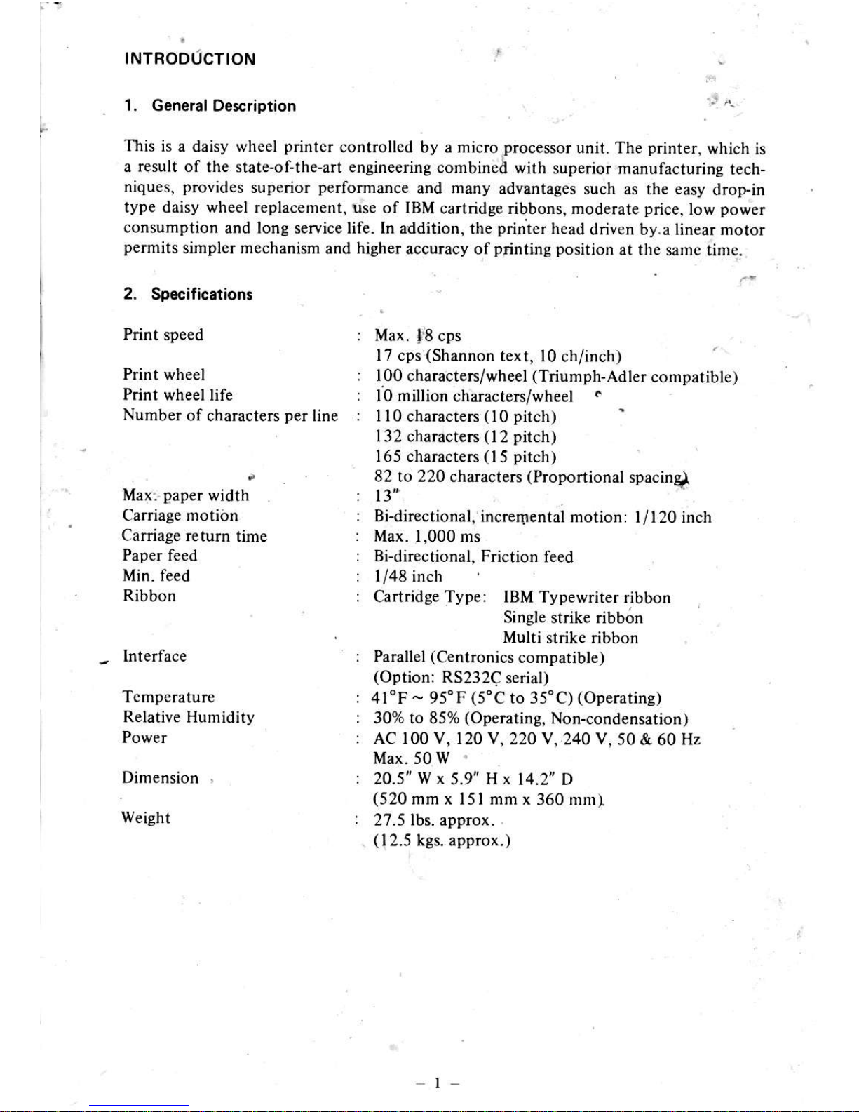
This
is a daisy wheel
printer
controlled by a micro
processor
unit. The
printer,
which is
a rqsult of
the state-of-the-art engineering
combined with
superior fianufacturing
tech-
niques,
piovides
superior
perfomance
and many advsntages
such as the easy
drop-in
type daisy
wheel replacement, use of IBM
cartridge ribbons, moderate
price,
low
power
consumption
and long service life. ln
addition, the
printer
head
driven by.a linear motor
permits
simpler mechanism
and
highe!
accuracy ofptinting
position
at the
same time.
Max:
paper
width
Carriage motidn
Carriage retum
time
Paper
ieed
Min. feed
Ribbon
-
Interface
Temperature
Relative
Humidity
Dimension
Weight
Max.
f8
cps
l7
cps
(Shannon
text, l0
ch/inch)
lO0
characteIs/wheel
(Triumph-Adler
compatible)
l0 million
characters/wheel
.
110
charactem
(10 pitch)
'
132
charactem
(12 pitch)
165
characters
(15 pitch)
82 to 220
characteN
(Proportional
spacing
Bldirectional,
increrlrentai motion:
I
/120
inch
Max. 1,000 ms
Bidirectional,
Friction
feed
1/48 inch
Cartridge Type: tBM Typewriter
ribbon
Single strike ribbon
Multi
strike ribbon
PaBllel
(Centronics
compatible)
(Option:
RS232C
serial)
4l"F - 95"F
(5'C
to
35'C)
(Operatins)
30% to 85%
(Operating,
Non-condensation)
AC 100 v,
120 v, 220 v, 240 v,
50 & 60 Hz
Max.sow'
20.5" W x
5.9"
Hx
14.2' D
(520
mm x l5l mm
x 360 mmI
27.5
lbs.
approx.
.
(12.5
kgs. approx.)
t-

INSTALLATION
OF THE PRINTER
1. Unpacking
Before
unpacking the
printer,
carefully
check the exterior
of the carton containing
rne
printer.
If any damaged
incurred during
transportation has
been found,
immedBr€ry
contact
the shop
you
bought the machine
1.1 Unpacking
procedurc
Unpack
the
printer
in accordance
with the iollowing
st€ps:
Step l: Open the carton.
Step 2: Pull out straight the
pdnter
together
v/ith its shock-absorbing
materials.
Step 3 : Place
the
printer
along
ivith the shock-absorbing
materials
on a table
ot
other
plain
spot.
Step 4: Remove
the shock-absorbing matedals
from
the
printer.
Step 5 :
Take the vinyl
cover off the
printer.
1.2 Rgpacking
the
printer
Repack the
printer
in reverce order from
unpacking
procedure.
Repack
the
printer
when storing
it o! sending
it for repair.
Caution
It is
advisable to keep
the
packing
materials for
possible
reshipment of
the
printer.
2. Checking ths Plinter Pan3
The
printer
is fumished
with the standard
accessories
shown below. If
any missed or
damaged
parts
have
been found out,
contact the source
ofyour
purchase.
fi,
o"o"
3. Single{trike
Ribbon
fu
o. e"*.
/-)
s.
oo",,tion
_#
code
\/
Manu.l
vtv
No. Name
Qlv
l.
2.
3.
5.
Daisy wheel
printer
Daisy wh€el
Single-strike
ribbon
Power cord
Operation Manual
I
I
1
I
I
2

3.
3.1
Initalling
the
Printer
Installing
locstion
lnstall
the
printer
with
attention
paid
to the
following.
(l)
Mount
the
printer
on a level
and tough
table
ofstand.
At this
time,
place
the
printer
so
that its rubber
feet
all
rest
on the
table
or stand
evenly.
(2)
Do
not install
the
printer
at
a
place
exposed
to
direct
sunlight,
or hot
or con-
taminated
air_
(3)
Do
not connect
the
printer
to a receptacle
used
also
for a large
motor,
cooler
or
other equipment
which
produce
electrical
noise.
(4)
Always
keep
the ambient
temperature
at 40
degee F
(5
degree
C) through
95 degree
F
(35
degree
C) while
operating
the
pri;ter.
Be careful
not
to subject
the
printer
to
shocks
or
a sudden
temperature
change.
Romoving
the
paper
table
protection
shegt
The
paper
table
and
platen
are wrapped
with
from
shocks
or
vibration
during
transportation.
this
sheet.
Remember
(o
set this
protection
sheet
on me
when
reshipping
the
printer.
3.2
If.it
is
difficult
to remove
the sheet,
open
or
take
olf
the soundprcofing
cover
to
take
the
sheet
out in
the following
way:
Step I :
Open
the
soundprooling
cover
towards
you
till
upright
position.
Step
2: Pull
up
and
lemove
the
soundproofing
cover.
a sheet
to
protect
the
pape!
table
Before
using
the
printer,
take
off
paper
table
as it
was originally
s€t
Knob
Pap€r
table
prot€ction
Soundproofing
cover

3.3
R€moving
the
fixars
The
carriage
is fixed with
two buffers which
protect
the carriage from shocks
or
vibration
during
transportation.
Keep
these cariage
fixers for
possible
reshipment in the future.
Step l: Hold the
printer
cover as shown below and lift it.
Step 2:
When the
cover
lock on
your
side has b€en disengaged,
draw
off
the cover
towards
you.
Step 3: Remove the right carriage fixer.
Step 4: Move the carriage to the riglt and remove the left
carriage
fixer. AC
corC
and ribbon can be taken out.
The
daisy motor is fixed not to slip out
during transportation.
Step Ir
Cht the
motor
band and rcmove it ftom
the carriage.
Step 2: Remove the lever fixer from
lhe carriaBe.
The
platen
is fixed with two materials
which
protect
the
platen
from
shocks or
vibration
dudng tmnsportation-
Step l: Remove the
platen
fixer from both
side of the
platen-
-4-
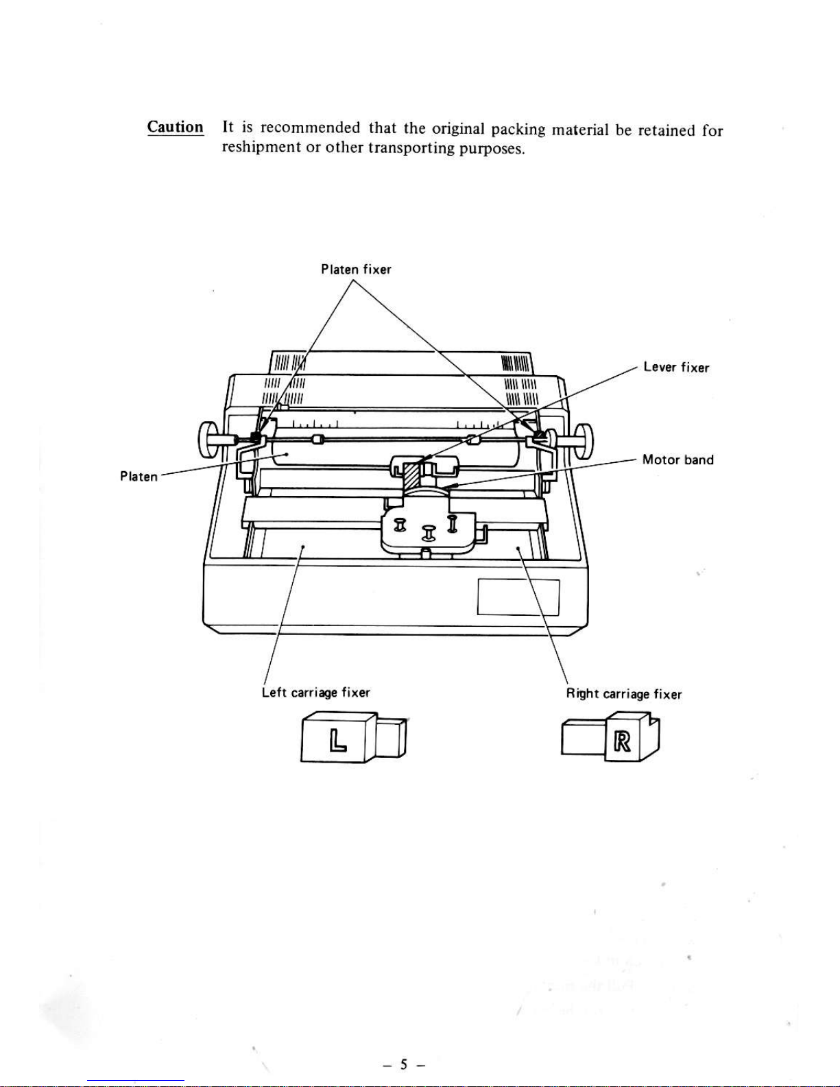
Caution lt is recommended
that
the original
packing
re5hipment
or
other lransponing
purposes.
material
be retained for
Right
carriag€ fixlr
r::r '------1"1
L-Elflr
L-18,
-5-

4.
s.ning !
c.rttidge
Ribbon
Eithei
a single
stdke
ribbon
or
multi strike
dbbon
can be
ured
When a cartridge
ribbon
has been
sei on
the
printer,
the
printer
will automatically
s€t
itself
for '
feed amount
suited
to that
ribbon.
step l:
Pu[
the ribbon
load
lever toward
you.
Step 2:
Pass the
lead
tape
of the ribbon
thrcugh
the thl€e
guides'
Step 3:
Push do*n
the
cartridge
until
it is
held by the
clip spring'
3.
Clip lp.ing
Turn L€lr
PICA
Turn
Right
ELITE
L Ribbon lo.d
l.wr
Step
4:
Tum the
cartridg;
knob
countertlockwise
dlection
until
the inked
pafi of the
ribbon
teaches
the
Printing
Part'
Step
5:
Retum
the
ribbon
load
levcr to
its original
position'
5.
Ribbon
lod l€v.t
Supplement:
Repllcing
a cartridge
ribbotr
whcn the
ribbon
is seen
to be
drnost
running
out
throwh
the
cT t'idge
slit'
replace
the
ribbon
in
the
following
prccedut€'
Step
l:
Pull
thc dbbon
load
lever
toward
you
Step
2:
Pull
up the
cadridge
off the
printer'
2.
Guide
(three
in total)
-------t'<-->-
(---)
GE=
EP
4. Knob
Carrridg.
tlit
f-t e:
-O
A<\'
gu

Ceutio4
(l)
Do not forcibly
pull
up
the cartridge without
puUing
the ribbon
load
lever
toward
you.
.
R ibbon lord tever
When
the end zone
of
ribbon
leaches to the
print position,
piinted
characteN could not
be lecognized clearly
Periodicaly
clean the ribbon
path
and lemove
paper
dust and ink
flake from
interior.
5. Atlrching
r D.iry Wh.el to tho Printot
The
dlopin design of the
daisy wheel
permits
easy
setting
and leplacement
of the daisy
wheel.
Stcp I i
Draw
the daisy
setting
lever
toward
you.
Step 2: Dlop the daisy wheel into
the daisy cale of
the
printer.
CNtion The
type surface of th€ daisy wheel should face
to the
platen.
Step 3: Push the
daisy s€tting
lever
to the front.
Supplement: Removing
the
daisy wheel.
Step l: Pull
the daisy setting
lever
toward
you.
St€p 2: Held
and
pull
up the
daisy wheel.
(2)
(3)
Rem.inins ribbon
RA
\Y/J
)
Oriry iatting
4,
"o>
'€.
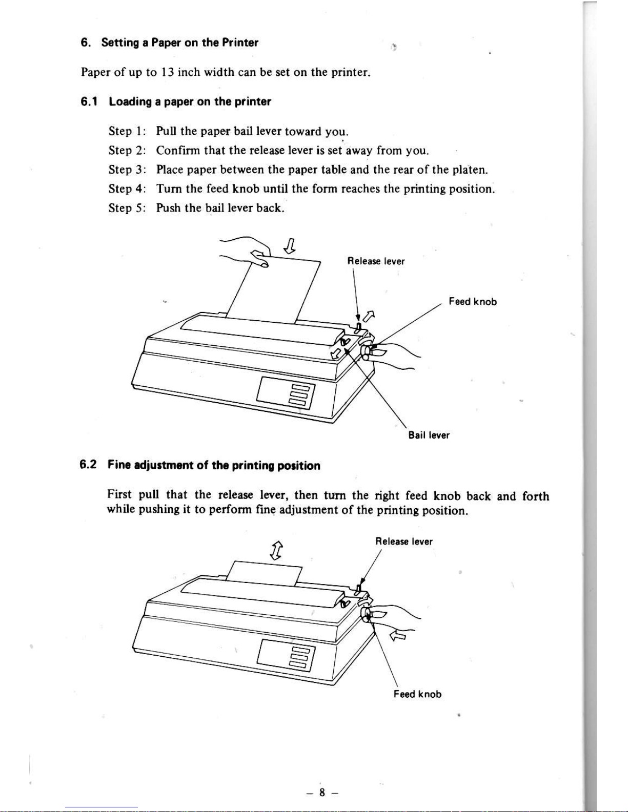
6. Seftino .
Pap6f
on tho
Printor
:
Paper of up to 13 inch width can be set on the
printer.
6.1 Loading I
papgr
on
tho
ptinter
Step l:
Pull
the
paper
bail
lever
toward
you.
Step 2: Confirm rhat the release lever is sei away from
you.
Step 3 : Place
paper
between the
paper
table and the rear of the
platen.
Step 4: Tum the feed knob until the form reaches the
printing position.
Step 5:
Push the bail lever back.
6.2 Fin diuttmnt
ot th.
primino polition
First
pul
that the rclcar€ lever,
then tum the riSht
feed knob
back rnd forth
while
pushing
it
to
perform
fin€ .djustment
of the
printinS positior.
Blil l.v.r
-8-

Corractin!
the
porition
of
a
plper
ii*tflrt
"t
the
printer
is crooked,
correct
it
in
ac@rdance
with
the
following
Step
1:
Pull
the release
lever
toward
you
Step
2: Open
the
soundproofing
cover
toward you.
..
Step
3: Align
the
side
edges
of
paper
as
shown
below
and
then
push
back
thc
rolease
lever-
Stqp
4:
Clote
the apoustic
cover
and
push
the
bail lever.

OPERATION
1. Switches and lndicators
The
power
switch
is
located
at the
panel
is located
at the right on
switches,
one
4-Step
selector slide
leit on the
back of the
printer
case, and the operation
the front.
The operation
panel
has thrce membrane
switch and three indicators.
1.1
Switchss
Power
SW:
Controls
the
primary
AC
power
supplied
to the
printer.
When
it is turned on the initial
state of the
pdnter
is:
(l)
LSI
(Line
Spacing Index)
fol.lows
to Dip SW.
(2)
CSI
(Column
Spacing Index) follo*s
to the switches on the operation
panel.
(3)
I-eft Margin is set at lst column.
(.4)
Right Maryin is set at the final column.
(5)
Horizontal Tab and Vertical Tab are not
set.
(6)
Top Margin is set at the top of
the
paper.
(?)
Bottom Margir is set at the end
of the
paper.
(&l
)
The
printer
is set
in
the on-line state, and READY lamp lights.
(8-2)
If
no
error
is
present,
CHECK lamp
goes
out.
(9)
Auto Backward Print Mode.
(10)
The
paper
length is set
at I I inches or 12.
(l
I ) Carriage is
positioned
at lst column.
(12)
The Print Wheel is
positioned
at the
home
position.
(
13) The Ribbon
is set at the
home
position.
(14)
The Power Indication kmp lights up.
/:N
.,'"a>.\
A",si'*
X.
.\y/
-10
(15)
Ready
lamp
lighrs up.
(16)
Remote
Mode.
Caution Before
tuming
on the
powet
switch, make
sure
that
papea
has
been
set on the
Drinter-
It is
important
to set
paper
correcdy
on the
printer
to obtain
the
best
pdnting
result.
Do not use
any other
AC
cord than
the }.core
cable turnished
with th€
printer.
Folm Fe€d
SW:
By
depressing
this switch, folm
feed
can be
performed
in the
pause
conditioir
and
paper
in fed
to as far as the
first line
or the
top maigin
of the
next
page.
Paure
SW:
Used to interrupt
the
operation
of the
printer
without erasing
the
data.
When
the
pause
switch
is
depressed, the
check
lamp will
light.
The
pause
is
leleased
by depressing
the rcs€t
switch.
Reset
SW:
Used
to release
the
pause,
check
ot eror
status.
The
check or errot
status is
released
by depressing
the rEsot
switch
after elimi
nating
the caus€.
Spacing
SW:
A 4-step
selector
slide switch
which
provides
s€lection
of
pS
(proportionaL
Spacing),
15
cpi,
12 cpiand
l0cpi.
S€t
this switch
at a
desired
spacing
before
powering
up
the
prilt€r.
C.hange
of the
spacing
pitch
retting
of this,witch
after
powering
up
the
printer
cal be made
by
the ESC
function
of
the host
computer.
-
ll
-
 Loading...