

Page 1
RT-15
Remote
Turn-On Turn-Off
Power Center
OWNER’S
MANUAL
OCTOBER 2008
Page 2

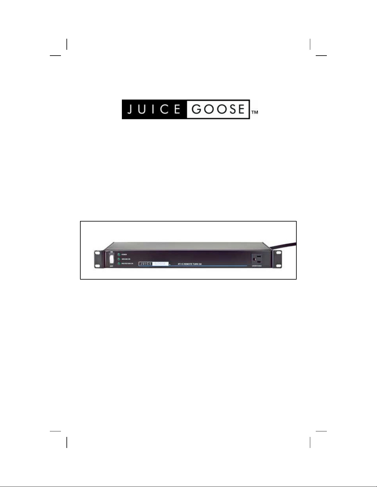
RT-15
REMOTE TURN-ON & TURN-OFF
POWER CENTER
The RT-15 provides a convenient means to remote
control a rack mounted power distribution center.
This unit allows switching on and off from the front
panel switch or a remote location. Features include
fire alarm triggered off, contact closure output and
optional AC line conditioning.
SAFETY PRECAUTIONS
The RT-15 is designed to operate on 120 volts, 60 hertz. Operation
with any voltage or frequency other than that can damage the equipment and create an unsafe situation.
CAUTION #1: The RT-15 must be grounded. If a power extension cord
is required, use a properly insulated and grounded cord. Failure to
ground the device could expose user to dangerous electric shock.
CAUTION #2: The RT-15 should be installed and used with only appropriate mounting hardware in a manner described in this document.
CAUTION #3: Do not expose the RT-15 to moisture or salty air. Doing
so could cause significant damage and create an unsafe condition.
CAUTION #4: Be sure the RT-15 is disconnected from main power
before opening the chassis to make wiring changes per instructions
in this manual.
DISCLAIMER
Juice Goose shall under no circumstances be held responsible for any
losses, damage, or injury resulting directly or indirectly from the use
of the RT-15 in a manner contrary with accepted safe operating methods or any instructions contained in this document. The user should
determine prior to use whether this product is adequate, suitable and
safe for the application intended. Since individual applications can be
subject to extreme variation Juice Goose makes no representation or
guarantee as to the suitability of the RT-15 for any generally described application.
2
Page 3

RT-15
DETAIL SPECIFICATIONS
CHASSIS……................................….….16 Gauge Steel with 11 Gauge Brackets
DIMENSIONS (inches)....................................……...…………......1.75H x 19W x 7D
WEIGHT (lbs)….………..……….......................................…………………………...15.0
CIRCUIT BREAKER…...….….....................................…...Back Panel, 15A Thermal
POWER INPUT......…..................……...7 Foot, 14/3 SJTW with NEMA 5/15P
VOLTAGE INPUT….................…...................………....………….120 VAC at 60 Hz
FRONT PANEL INDICATOR LED
Power On...................................................................................................................Green
External Fault (RX Option Only).................................................................Red
Power Protection OK (RX Option Only)..........................................Green
POWER OUTPUT RECEPTACLES
Switched……..….……...............……..…..................…….Six NEMA 5/15R
Unswitched.................................................................................Two NEMA 5/15R
POWER LINE FILTRATION - RX SERIES (Optional)
Transient Energy Absorbtion..................................................1,020 Joules
Maximum Applied Current.................3,000 Amps @ 6,000 Volts
Maximum Let Through Surge..................10 Volts (Line to Neutral)
AC Line Noise Filtration............................<60 dB L-N, <80 dB N-G
REMOTE CONTROL CONTACTS - INPUT AND OUTPUT
Two Position Phillips Screw terminals
Maximum Current Rating......................................................................15 Amps
Wire Size.............................................................................................24 to 12 AWG
OUTPUT RELAY CONTACT RATING (Maximum)
10 Amps @ 380 VAC or 125 VDC
INPUT RELAY COIL RATING
83 mA, 144 Ohms
Page 4

NEMA 5-15R
Unswitched (2)
NEMA 5-15R
Switched (6)
ACCESSORY
OUTPUT CONTACT
TERMINAL
120VAC
120VAC
JUMPER FOR
REMOTE CONTROL
120VAC RELAY
120VAC
12 VAC
12VDC RELAY
Front Panel Switch
OPTIONAL
RX SERIES
POWER
PROTECTION
MAINS
POWER
4
JUMPER FOR
REMOTE
CONTROL
CIRCUIT BREAKER
CONTACTS
LOCAL CONTROL
Page 5

GENERAL DESCRIPTION
The Juice Goose RT-15 is a 15 amp, rack mounted power distribution module that can be turned on and off locally and by
way of remote contact closure. It also features a dry contact
closure on power activation as well as optional, high performance AC power filtration and protection.
The device is intended for application where a) only a single
remote circuit needs to be controlled, b) emergency alarms
systems require an automatic turn on or turn off and/or c)
an output contact closure is required to trigger electronic
equipment that may be powered but is operating in a standby mode.
CHASSIS FRONT FEATURES
Power Switch - As set up at the factory, the power switch on
the front controls the turn on and turn off of the RT-15. In
this configuration the internal low voltage switch lead is connected to the “Switch” position on the RT-15 circuit board and
a wire jumper is attached across the “Input” terminals on the
back of the chassis. The switch will function ONLY in this
configuration.
Power On LED - This light will be illuminated green when the
RT-15 has been turned on.
External Fault
(Only with RX Series Line Conditioning Option) - This light will
be illuminated red in the event of a wiring fault outside the
RT-15. Such faults include open ground, faulty neutral connection and power line voltage in excess of 150 VAC. The RT-15
with optional line conditioning will not turn on under these
fault conditions.
Protection OK
(Only with RX Series Line Conditioning Option) - This light will
illuminate green when the RT-15 is turned on and there are no
line faults. In this condition the RT-15 will be providing AC line
surge protection and noise filtration.
AC Power Receptacle - Electric power is available from this
outlet whenever the RT-15 is plugged in. (See External Fault)
Page 6

CHASSIS BACK FEATURES
AC Power Cord - Insulated 14 AWG power cord with 15 amp
(NEMA 5-15P) plug
Circuit Breaker - 15 amp Thermal
Switched Receptacles (6) - These NEMA 5-15R duplex receptacles are turned on and off with the local or remote control of
the RT-15
Unswitched AC Receptacle - Electric power is available from
this outlet whenever the RT-15 is plugged in. (See External
Fault)
Remote Control Terminals - Two position terminals allow dry
contact closure remote activation and contact closure output.
SET-UP & INSTALLATION
LOCAL CONTROL
The RT-15 is configured at the factory to allow power turn on
and off control with the switch on the front of the unit. This
local control is possible because of two default set up features. First, there is a factory installed jumper across the remote control “Input” terminal on the back of the chassis. Second, inside the chassis a low voltage lead is attached to the
RT-15 circuit board in a position labeled, “SWITCHED”.
REMOTE CONTROL
For remote activation the low voltage lead on the RT-15 board
must be moved from the “SWITCHED” to the “ON” position.
(Failure to make this change will allow the switch on the front
of the chassis to turn the RT-15 off when it otherwise would
be on via remote control.)
Be sure the RT-15 is unplugged before opening the chassis for
any reason. To remove the chassis top remove the three
screws from each side of the chassis that hold the chassis
top in place. Carefully pull the chassis top up from the main
chassis assembly. Move the wire connected to the SWITCHED
position (J8) on the circuit board to the ON position (J6). This
will disconnect the switch from the power control circuit and
directly wire that portion of the circuit. Replace the chassis
top and secure with the six screws.
6
Page 7

Remove the factory installed jumper across the REMOTE INPUT
terminal. This terminal should then be connected to a latching
switch at the desired remote location. This remote switch should
provide only a dry contact closure, without voltage.
The RT-15 contains a 12VDC power supply inside the chassis to
provide coil latching power for the control relay. No external
power supplies are needed other than any required to operate
remote control or alarm contacts.
In this configuration the remote contact closure will cause the
RT-15 to turn on. Opening this contact will cause the RT-15 to
turn off. (NOTE: The Unswitched outlets on the front and back
will be live whenever the RT-15 is plugged in and will NOT turn
off with either the local or remote switch.)
FIRE ALARM SHUTDOWN
Should it be desired that the RT-15 be forced off in the event of
a fire or other similar alarm, in either a local or remote control
configuration, the INPUT contact terminal should be connected
to a relay that is held closed in non-alarm conditions. When this
contact opens the RT-15 will turn off regardless of the position
of either the local or remote switch.
ACCESSORY CONTACT OUTPUT
A second terminal on the back of the RT-15 chassis provides a
dry contact closure (i.e. no voltage) when the unit is turned on.
This terminal is attached to a normally open relay inside the
chassis. It can be used to activate powered equipment which
may be in “stand-by” mode. It can also be used to turn on another RT-15.
OPTIONAL POWER CONDITIONING
As an optional feature, the RT-15 may contain the Juice Goose
RX Series Hybrid AC Filter. This protection circuit provides
60dB to 80dB of line noise reduction in addition to AC surge
protection on both normal (line — neutral) and common (neutral
— ground) modes. Surge protection reduces strikes of up to
6,000 volts to no more than 10 volts. RX Series protection also
provides over voltage shutdown and protection against wiring
faults.
Page 8

The front of the RT-15 chassis contains one status light (LED)
on models that do not include the RX Series protection. Models
with the protection circuit have three status lights.
TROUBLE SHOOTING
The RT-15 is ruggedly constructed from high quality components to give years of dependable power for your equipment.
In the unlikely event of poor performance, however, the following checklist is included to aid diagnosing a problem.
UNIT WILL NOT TURN ON
- For local operation: Check that the jumper on the
Input terminal is in place. Also, unplug the RT-15 and remove
the top. Check that the low voltage lead is connected to either
the Switch or the On positions on the RT-15 circuit board. Replace the top before plugging in.
- For remote control: Check that the low voltage lead
is in the On position on the RT-15 circuit board. If this lead is
in the Switch position the switch on the front of the RT-15
chassis can turn the unit off.
- Only for models with the RX Series protection circuit: Check the indicator lights on the front of the chassis. If
the External Fault light is red this indicates either ground or
neutral fault or excessive line voltage. The RT-15 will not turn
on under these circumstances. Unplug the unit and consult a
professional regarding the facility’s wiring problems.
- Check that the unit is plugged in and turned on.
- Check the circuit breaker on the back. In cases of
malfunction or current overload the circuit breaker will open.
After a brief period, the circuit breaker can be reset by pushing in the breaker button. If this problem repeats check that
the current requirement of the equipment plugged into the 120
VAC outlets is not greater than 15 amps.
SERVICE
Should your unit require service, contact Juice Goose to receive a service authorization number. This number will allow
us to track your returned unit. Please note that no returns will
be accepted without such a number.
(e) info@juicegoose.com www.juicegoose.com
7320 Ashcroft, Suite 104
Houston, Texas 77081
(p) 713-772-1404 (f) 713-772-7360
8
 Loading...