

Page 1

U P S
Uninterruptible Power System
Xtreme Value Rack Tower (XVRT)
Line-Interactive Rack-Mount
Network UPS
600VA/ 1000VA/ 1200VA
1500VA/ 2200VA/ 3000VA
Page 2

■ USER‘S MANUAL■
Page 3

Table of contents
Table of contents................................................................................. 3
Introduction......................................................................................... 3
1. Important Safety Instructions ......................................................... 4
2. Presentation..................................................................................... 5
3. Installation ...................................................................................... 8
4. Operation .......................................................................................11
5. Software and Computer Interface................................................. 12
6. Battery Cabinet............................................................................. 13
Appendix a Troubleshooting............................................................. 13
Appendix b Specifications................................................................ 14
Obtaining Service ............................................................................. 15
Warranty............................................................................................ 16
Introduction
Please read and save this manual!
Thank you for selecting this uninterruptible power system (UPS). It provides you
with a perfect protection for connected equipment. The manual is a guide to install
and use the UPS. It includes important safety instructions for operation and
correct installation of the UPS. If you should have any problems with the UPS,
please refer to this manual before calling customer service.
Please save or recycle the packaging materials!
The UPS‘s shipping materials are designed with great care to provide protection
within delivery. These materials are invaluable if you ever have to return the UPS
for service. Damage happened during transit is not covered under the warranty.
Intelligent microprocessor control
The UPS is a microprocessor-controlled unit. This means that it operates with the
newest technology, high performance and powerful function.
The UPS is an intelligent protector and provides pure, reliable AC po wer to the
critical loads - protecting them from utility power blackout, swells, sags and
interference.
3
Page 4

Furthermore, in order to save the battery energy, the UPSs can automatically turn
it off under backup mode if none of the connected loads is operating.
Advanced battery management
The visual and audible indications of the UPS present the battery’s status. The
self-test function allows the UPS to detect a weak battery before it is put into
service. The UPS normally performs a self-test at power up condition.
1. Important Safety Instructions
● SAVE THESE INSTRUCTIONS - This Manual Contains Important
Instructions that should be Followed during Installation and Maintenance of
the UPS and Batteries.
● Intended for Installation in a Controlled Environment.
● Servicing of batteries should be performed or supervised by personnel
knowledgeable of batteries and their required precautions. Keep
unauthorized personnel away from batteries.
● When Replacing Batteries, replace With the Same Number and Type
CAUTION - Do Not Dispose of Battery or Batteries in a Fire, The Battery
●
May Explode.
●
CAUTION - Do Not Open or Mutilate the Battery or Batteries, Released
Electrolyte
is Harmful to the Skin and Eyes. It May be Toxic.
●
CAUTION - A Battery can present a Risk of Electrical Shock and High Short
Circuit Current. The Following Precautions Should be Observed When
Working on Batteries:
Remove watches, rings or other metal o bjects.
Use tools with insulated handles.
Wear rubber gloves a nd boots.
Do not lay tools or meta l parts on top of batteries.
Disconnect charging source prior to connecting or disconnecting battery
terminals.
4
Page 5
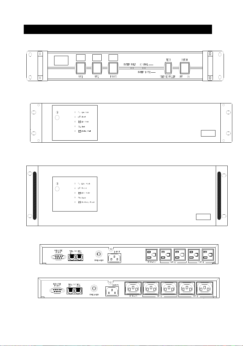
2. Presentation
Front Panel (600VA/ 1000VA), 1U size
Front Panel (1200VA/ 1500VA), 2U size
Front Panel (2200VA/ 3000VA), 3U size
Back Panel (600VA/ 1000VA), 1U size
Back Panel (1200VA/ 1500VA), 2U SIZE
5
Page 6
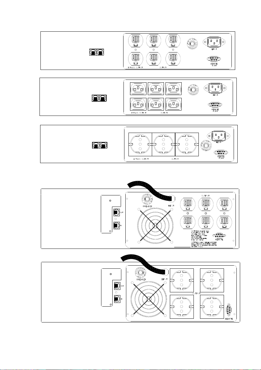
(1500VA/110V NO BYPASS OUTPUT)
Back Panel (2200VA), 3U SIZE
6
Page 7
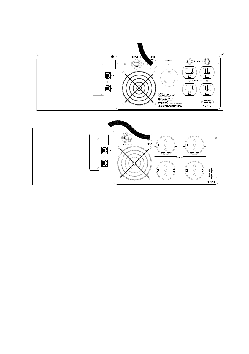
Back Panel (3000VA), 3U SIZE
2.1 “Power On” Indicator
Power On indicator illuminates when utility power’s condition is normal.
2.2 “BACKUP” indicator
The indicator illuminates when the power is supplied from the batteries.
2.3 “Battery Fault” Indicator
This illuminates indicating weak battery. Recharge the battery for at least four
hours. If after recharging this is still illuminated, replace the battery by following
the instructions in the manual.(You can plug out then check battery)
2.4 Power Switch
Can be used as the master on/off switch of your equipment by leaving your
equipment connected to UPS and switched on.
2.5 UPS Outlets
Provide instantaneous back-up power protection to your equipment. Supply
temporary uninterrupted operation for your equipment during power failure.
2.6 Bypass Power Sag Outlets
Provides bypass power sag protection to your equipment. Prevent power
7
Page 8

problems traveling through your system via unprotected peripherals.
2.7 Circuit Breaker Protection
Serves as an overload and fault protection. This is a critical component of the
advanced UPS
2.8 “Phone Jack” Communications Ports
Telecom transfer ports provide users to extend the applications.
● Caution: To reduce the risk of fire, use only No. 26AWG or larger
telecommunication line cord.
2.9 communication function
Provide RS-232 interface and UPSMON software to support NOVELL, UNIX,
DOS, WINDOWS and other operating systems.
3. Installation
Inspect the UPS upon receipt. The packaging is recyclable; keep it for reuse o r
dispose of properly.
3.1 Recharge the battery
UPS may be used by anyone immediately upon receipt. The battery is fully
charged before shipping from the factory. However, the user is recommended to
recharge the battery for at least eight hours before using UPS. Energy loss may
occur during shipping or long duration storage. To recharge the battery, simply
plug in the UPS to a wall outlet and let it charge.
3.2 Connect the loads
Plug your primary equipment (e.g. computer, monitor and critical data storage
device, etc.) to the Battery Power-Supplied outlets. Plug your peripheral
equipment (e.g. printer, scanner, fax, or audio device) to the bypass outlets. Do
not plug a laser printer into the UPS output outlets, as its power demand is much
higher than typical peripherals and may cause the circuit breaker to trip. It is
suggested to connect similar heavy loads (like laser printer) to the bypass
outlets.
3.3 Connect the telephone
If you wish to protect a fax or a modem, connect the telephone cable from the wall
outlet to the “IN” jack. Connect the telephone cable (provided) from the “OUT” jack
to the fax or modem. To protect a10Base-T (UTP) network interface, obtain and
use a UTP cable to connect the “OUT” jack to your computer.
3.4 Connect to the utility power
Plug UPS to a 2-pole, 3-wire grounding receptacle. Make sure the branch is
protected and does not service equipment requiring heavy electricity (e.g.
refrigerator, air conditioner, copier, etc.). Avoid using extension cords; if used,
make sure they are rated for at least 15 Amps (A).
Special Note:: concerning connection to utility power
Circuit Overcurrent Protection - "CAUTION - To reduce the
risk of fire, connect only to a circuit provided with 30
amperes maximum branch circuit overcurrent protection in
accordance with the National Electric Code, ANSI/NFPA 70".
3.5 UPS self-test
UPS will conduct a self-test once switched on it each time. Do not add or take off
8
. Size of Branch
Page 9

any equipment while UPS conducts self-test; await it until the Power indicator
lights up. Besides this, switch on your equipment after the UPS is switched on..
3.6 Battery auto-charging
Once the power cord is connected, the battery of the UPS will be automatically
charged by the UPS..
3.7 Overload protection
If an overload situation is detected during the self-test, UPS audible alarm will
activate, emit a long beep and automatically shut down the system. Unplug at
least one piece of equipment from the Battery Supplied Outlets. Switch off UPS,
wait 5 seconds and check to make sure the circuit breaker is set then switch on,
again.
3.8 Optimal battery status
To maintain the optimal status of battery, make sure the UPS remains plugged in..
3.9 Self-protection feature
UPS is equipped with a self-protection feature preventing people users from
damaging the unit. It is programmed so that once switched off, the user must wait
5 seconds before switching UPS on again.
3.10 Storage
To store UPS, cover it and store it with the battery fully charged. During extended
storage, recharge the battery every three months to ensure battery life.
3.11 Power failure
When the event of power failure occurs after turning on UPS, and prior to the
self-test sequence, UPS will automatically shut down and not restart until utilit y
power is restored. This is necessary to check the quality of po wer that is delivered
to your connected equipment.
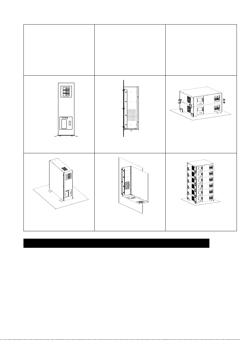
3.12 Installation with accessories of “Rack-mount” types:
Please install the rack-mount type units according to the following
illustration.
9
Page 10
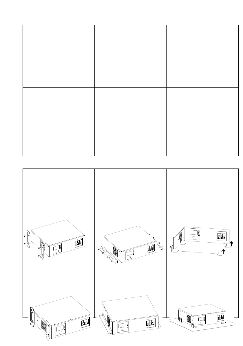
Installation with bottom plate.
Part
RMB-08 (1U),
RMB-09 (2U),
RMB-10 (3U),
RMB-11 (4U)
2 PCS.
Step 1
Installation with bottom
bracket.
Part
RMB-12 (1U~4U)
2 PCS.
Step 1
Installation with rear
bracket
Part
RMB-13,
RMB-14 (2U-4U)
4 PCS.
Step 1
10
Page 11
Step 2
Step 3
Step 4
Step 2
Step 3
Step 4
Step 2
Step 3
Step 4
4. Operation
4.1 Simple test
It is recommended that the user perform a simulation test when using UPS for
the first time or when adding an additional piece of equipment. Conduct a
simulation-test: first, switch on UPS and wait for the power indicator to light up,
then simply unplug UPS to simulate the event of utility failure.
4.2 Check the power requirement of your equipment
4.2.1. Make sure the total power of your equipment does not exceed rating
capacity.
11
Page 12

4.2.2. Also make sure the equipment you plugged into the Battery
Power-Supplied outlets does not require total power exceeding the capacity of
the UPS. Otherwise, overload may occur and cause the circuit breaker to trip. If
the power requirement of your equipment differs from VA, convert the
requirement power into VA by doing the calculations below:
4.2.3. If the power requirement of your equipment is listed other than VA,
convert the requirement into VA by doing the calculations below.
Watt (W) X 1.67 = VA, or Amps(A) X 120= VA (For
100-120V model)
Watt (W) X 1.67 = VA, or Amps(A) X 230= VA (For
220-240 model)
4.3 Limited rating power of UPS
When utility failure occurs, the UPS output outlets will supply power to your
equipment from its battery and the alarm will beep every 5 seconds. Be sure
that your equipment is running under the limited rating power. To restore the
utility by plugging UPS back in to the existing power source. Repeat the test a
few times to make sure UPS works properly and to find out the expected
runtime.
5. Software and Computer Interface
5.1 Power Monitoring Software
The UPSMON series software (or other power monitoring software) is applied
via a standard RS-232 interface to perform monitoring functions, and then
provides an orderly shutdown of a computer in the event of power failure.
Moreover, UPSMON displays all the diagnostic symptoms on the monitor, such as
Voltage, Frequency, Battery level and so on. The software is available for DOS,
Windows 3.1x, Windows 95/97/2000/ME/XP, Windows NT or later, Novell Netware,
Linux and others. Call your dealer for more information on computer OS
compatible solutions.
5.2 Interface Kits
A series of interface kits is available allowing UPS monitoring. Each interface kit
includes the special interface cable required to convert status signals from the
UPS into signals which individual operating system recognize. The interface cable
at UPS side must be connected to the REMOTE PORT, at computer side the
connection can be either COM 1 or COM 2. For other installation instructions and
powerful features, please refer to READ.ME file contained within the UPSMON
software.
5.3 The characteristics of the computer interface port
The computer interface port has the following characteristics:
The communication port on the back of the UPS may be connected to host
computer. This port allows the computer to monitor the status of the UPS and
control the operation of the UPS in some cases. Its major functions normally
12
Page 13

include some or all of the following:
To broadcast a warning when power fails.
To close any open file before the battery is exhausted.
To turn-off the UPS.
Some computers are equipped with a special connector to link with the
communication port. In addition, special plug-in cord may be needed. Some
computers may need special UPS monitoring software. Contact your dealer for the
details on the various interface Kits.
Attention: UPSMON software and interface port function just available for
model name
with “P” affix. The standard RS-232 cable (pin to pin D-SUB 9 pin cab le) can be
connected
between UPS REMOTE PORT and computer COM port for the UPSMON series
software.
UPSMON software can be free download from www.xpcc.com
6. Battery Cabinet
6.1 Battery’s life of UPS
The battery’s life of UPS is about 3-6 years under normal usage.
6.2 Battery Replacement
Once the UPS’s battery is no longer useful and must be replaced. Pleas e call the
service personnel to replace it.
Appendix a Troubleshooting
UPS has a self-protect feature that prevents the UPS from being
damaged as a result of overheating. If the temperature is higher than
55°C, wait for a while and allow t the UPS to cool down..
13
Page 14

Problems Possible Cause Solution
Full-time Bypass
outlets stop providing
power to the
equipment
Circuit breaker button
popped up as a result of
overload.
Unplug at least one piece of
equipment from the Full-time Bypass
outlets.
Switch off UPS, wait 5 seconds, reset
the circuit breaker (press down
breaker button), then switch on UPS.
UPS doesn’t perform
to its expected
runtime.
Battery undercharged or
depleted due to frequent
power outages.
The power required by your
equipment slightly exceeds
Recharge the battery by leaving the
UPS plugged in and switched on.
Unplug at least one piece of
equipment from the UPS outlets.
the capacity of the UPS.
UPS cannot be
turned on.
The battery is slightly
worn-out.
Special UPS is designed to
prevent damage from
flipping.
Call the service personnel to replace
the battery.
Switch UPS off, wait for 5 seconds,
then switch UPS on.
The battery is worn-out. Replace the battery by following the
instructions in this manual.
Mechanical problem. Contact your sales representative.
Appendix b Specifications
MODEL 600VA 1000VA 1200VA
Input Capacity (On Battery) 600VA/360W 1000VA/600W 1200VA/720W
Voltage +/-25% at line input
Frequency 50 or 60 Hz +/-10% (auto sensing)
Voltage (on battery) Simulated sine wave at 100V/115V/230V +/- 5% Output
Frequency (on battery) 50 or 60 Hz +/- 0.5%
(Surge
protection)
500VA 500VA 500VA
14
Page 15

Protection
and
Filtering
Battery
MODEL
Voltage Regulation
(AVR)
Transfer Time 2/4 milliseconds, including detection time
Spike Protection 320 Joules, 2ms
EMI/RFI filter 10Db at 0.15MHz,50dB at 30MHz
Overload Protection
Unit Input For overload & Short circuit protection
10Base-T Cable Port Network (UTP, RJ-45) compatible jacks
Short Circuit UPS output cut off immediately or input fuse protection
Type Sealed, Maintenance-free lead acid
Typical Recharge Time 8 hours (to 90% of full capacity)
Protection Automatic self-test & discharge protection, Replace battery indicator
Back-up Time 3– 180 min (depending on computer load)
AVR automatically increase output voltage 15% above input voltage
if –9% to –25% of nominal. AVR decrease output voltage 13% below
UPS automatic shutdown if overload exceeds 110% of nominal at 60
input voltage if +9% to +25% of nominal
seconds and 130% at 3 seconds
1500VA 2200VA 3000VA
Input Capacity (On Battery) 1500VA/900W 2200VA/1320W 3000VA/1800W
Output
Voltage +/-25% at line input
Frequency 50 or 60 Hz +/-10% (auto sensing)
Voltage (on battery) Simulated sine wave at 100V/115V/230V +/- 5%
Frequency (on battery) 50 or 60 Hz +/- 0.5%
Voltage Regulation
(AVR)
(Surge
protection)
500VA for 220~240V
Models only
AVR automatically increase output voltage 15% above input voltage
if –9% to –25% of nominal. AVR decrease output voltage 13% below
input voltage if +9% to +25% of nominal
N/A N/A
15
Page 16

Transfer Time 2/4 milliseconds, including detection time
Spike Protection 320 Joules, 2ms
EMI/RFI filter 10Db at 0.15MHz,50dB at 30MHz
Protection
and
Filtering
Battery
Overload Protection UPS automatic shutdown if overload exceeds 110% of nominal at 60
seconds and 130% at 3 seconds
Unit Input For overload & Short circuit protection
10Base-T Cable Port Network (UTP, RJ-45) compatible jacks
Short Circuit UPS output cut off immediately or input fuse protection
Type Sealed, Maintenance-free lead acid
Typical Recharge Time 8 hours (to 90% of full capacity)
Protection Automatic self-test & discharge protection, Replace battery indicator
Back-up Time 3– 180 min (depending on computer load)
MAXIMUM Ambient Temperature
For Operation
0-35C for Ambient operation
All trademarks are property of their respective owners. Specifications
subject to change without notice.
O
BTAINING SERVICE English
If the UPS requires Service:
1. Use the TROUBLESHOOTING section to eliminate obvious
causes.
2. Verify there are no circuit breakers tripped
3. Call your dealer for assistance. If you cannot reach your
dealer, or if they cannot resolve the problem call or fax Xtreme
Power Technical Support at the following numbers; Voice
phone_, Fax line_ or Contact Xtreme Power at 800-582-4524.
16
Page 17

Please have the following information available BEFORE calling
the Technical Support Department:
A. Your name and address.
B. Where and when the unit was purchased.
C. All of the model information about your UPS.
D. Any information on the failure, including LEDs that may not
be illuminated.
E. A description of the protected equipment, including model
numbers if possible.
F. A technician will ask you for the above information and, if
possible, help solve your problem over the phone. In the event
that the unit requires factory service, the technician will issue
you a Return Material Authorization Number (RMA #).
G. If the UPS is under warranty, the repairs will be done at no
charge. If not, there will be a charge for repair.
4. Pack the UPS in its original packaging. If the original
packaging is no longer available, ask the Technical Support
Technician about obtaining a new set. It is important to pack
the UPS properly in order to avoid damage in transit. Never
use Styrofoam beads for a packing material.
A. Include a letter with your name, address, daytime phone
number, RMA number, a copy of your original sales receipt, and
a brief description of the problem.
5. Mark the RMA # on the outside of all packages. The factory
cannot accept any package without the RMA # marked on the
outside.
6. Return the UPS by insured, prepaid carrier to: Call Xtreme
Power at 800-582-4524
17
Page 18

Limited Three Year Warranty
XVRT Series UPS products are warranted free from defects in
material and workmanship for three years from date of purchase.
This warranty is limited to repairing or replacing, at Xtreme
Power’s sole option, any defective component, circuit board or
module contained within the product, only when it is returned with
an Xtreme Power Return Material Authorization (RMA) number to
Xtreme Power. Xtreme Power may, at its sole discretion, offer field
repairs with warranty coverage limited to parts and labor only.
Batteries
Batteries, included in this product are warranted for two years.
Batteries are deemed defective by Xtreme Power’s sole discretion
Limitations of Warranty
This limited warranty does not cover any losses or damage
resulting from shipment to or from the customer, or from improper
installation, inappropriate environment, abuse, modifications,
adjustments, or unauthorized repair. Policies & Procedures
Exclusive Remedies
Except as set forth herein and except as to title, there are no
warranties, express or implied, or any affirmations of fact or
promises by Xtreme Power for the products, their merchantability,
or fitness for any particular purpose. In no event shall Xtreme
Power be liable for lost profits, goodwill, or any other special or
18
Page 19

consequential damages. Any changes to this must be approved by
an Xtreme Power corporate officer.I. Life Critical Applications
Life Support Disclaimer
Xtreme Power power protection products are not designed,
intended or authorized for use in systems intended to support or
sustain life, or for any other application in which the failure of the
Xtreme Power product could create a situation where personal
injury or death may occur. Under no circumstances should the
Buyer purchase or use Xtreme Power products for any such
unintended or unauthorized application, if the Buyer does not
comply with this, the Buyer shall indemnify and hold Xtreme Power
and its officers, employees, affiliates, resellers, partners and
distributors harmless against all claims, costs, damages and
expenses, and reasonable attorney fees arising out of, directly or
indirectly, any claim or personal injury or death associated with
such unintended or unauthorized use, even if such claim alleges
that Xtreme Power was negligent regarding the design or
manufacture of the product..
Term of Service
Logistics and Shipping
Unless otherwise stated, the warranty period begins on the date
the Xtreme Power product is shipped to the customer when shipped
from an Xtreme Power owned facility. In cases in which products
are purchased through and shipped from a Distributor or a Reseller,
the warranty period begins 60 days from the date of shipment from
Xtreme Power. If a Xtreme Power product is found to be defective,
Xtreme Power will, at its sole discretion either ship the customer a
19
Page 20

new replacement product or repair the returned product. The
customer must return the defective unit to Xtreme Power within 30
days of issuance of the RMA or will be charged full price for the
replacement unit.
20
 Loading...