

Page 1

UNINTERRUPTIBLE POWER SUPPLY (UPS)
P90 Online UPS
1000VA, 1500VA, 2000VA, 3000VA Models
USER & INSTALLATION MANUAL
www.xpcc.com | © 2013 Xtreme Power Conversion Corporation. All rights reserved.
Page 2

P90 USER’S MANUAL UNINTERRUPTIBLE POWER SUPPLY (UPS)
Table of Contents
EMC Statements - FCC Part 15 ................................................................ 4
IMPORTANT SAFETY INSTRUCTIONS: ................................................. 5
INTRODUCTION ........................................................................................... 7
PRODUCT DESCRIPTION .......................................................................... 7
Double Conversion On-Line Technology ................................................................................................... 7
Diagnostic Tests ........................................................................................................................................ 8
SYSTEM CONFIGURATION ........................................................................ 8
Communication Connections .................................................................................................................. 11
RS232 Communications ...................................................................................................................... 12
SNMP Communications Option ........................................................................................................... 12
Emergency Power Off (EPO) Port ........................................................................................................... 12
HARDWARE INSTALLATION GUIDE ................................................... 13
UPS Installation ....................................................................................................................................... 14
Connecting the batteries .................................................................................................................... 14
Rack-mount Installation (using front brackets) .................................................................................. 16
Rack-mount Installation (using 4-post rail kit) .................................................................................... 17
Tower Installation ............................................................................................................................... 20
UPS Input Connection ......................................................................................................................... 21
UPS Output.......................................................................................................................................... 21
Starting the UPS ...................................................................................................................................... 21
Software Installation ............................................................................................................................... 22
Battery Replacement .............................................................................................................................. 22
OPERATIONS ............................................................................................. 25
Button Operation .................................................................................................................................... 25
LCD Panel ................................................................................................................................................ 26
Audible Alarms: ....................................................................................................................................... 27
Abbreviations in LCD Display .................................................................................................................. 28
Xtreme Power Conversion Corporation (Rev 8/29/13) Page 2
Page 3

P90 USER’S MANUAL UNINTERRUPTIBLE POWER SUPPLY (UPS)
UPS Setting .............................................................................................................................................. 29
Output Voltage Settings ...................................................................................................................... 29
Frequency Converter enable/disable.................................................................................................. 29
ECO enable/disable ............................................................................................................................. 30
AECO enable/disable ........................................................................................................................... 30
Bypass Mode enable/disable .............................................................................................................. 31
Programmable Outlets enable/disable ............................................................................................... 31
Programmable Outlets Setting ........................................................................................................... 31
LCD Display Direction Setting .............................................................................................................. 32
Acceptable Input Voltage Range Settin .............................................................................................. 32
Exit Setting .......................................................................................................................................... 32
Operating Mode Description .................................................................................................................. 33
Fault Reference Codes ............................................................................................................................ 35
Warning Indicators .................................................................................................................................. 36
TROUBLESHOOTING ............................................................................... 37
STORAGE AND MAINTENANCE ............................................................ 39
Storage .................................................................................................................................................... 39
Maintenance ........................................................................................................................................... 40
BATTERIES................................................................................................. 41
REPLACING THE BATTERY ....................................................................................................................... 41
SPECIFICATIONS ...................................................................................... 42
OBTAINING SERVICE............................................................................... 45
XTREME POWER CONVERSION® CORPORATION LIMITED
WARRANTY ............................................................................................... 46
Xtreme Power Conversion Corporation (Rev 8/29/13) Page 3
Page 4

P90 USER’S MANUAL UNINTERRUPTIBLE POWER SUPPLY (UPS)
Thank you for selecting this uninterruptible power supply (UPS). It provides you with protection for
connected equipment. Please read this manual before installing the P90-Series UPS models P90-1000,
P90-1500, P90-2000 and P90-3000 as it provides important information that should be followed during
installation and maintenance of the UPS and batteries, allowing you to correctly set up your system for
the maximum safety and performance. Included is information on customer support and service, if it is
required. If you experience a problem with the UPS, please refer to the Troubleshooting section in this
manual to correct the problem. If the problem is not corrected, please collect information so that the
Technical Support personnel can more effectively assist you.
EMC Statements - FCC Part 15
Notice:
pursuant to Part 15 of the FCC Rules. These limits are designed to provide reasonable protection against
harmful interference when the equipment is operated in a commercial environment. This equipment
generates, uses, and can radiate radio frequency energy and, if not installed and used in accordance with
the instruction manual, may cause harmful interference to radio communications. Operation of this
equipment in a residential area is likely to cause harmful interference in which case the user will be
required to correct the interference at the users own expense.
Modifications not expressly approved by the manufacturer could void the user’s authority to operate the
equipment under FCC rules.
This equipment has been tested and found to comply with the limits for a Class A digital device,
Xtreme Power Conversion Corporation (Rev 8/29/13) Page 4
Page 5

P90 USER’S MANUAL UNINTERRUPTIBLE POWER SUPPLY (UPS)
IMPORTANT SAFETY INSTRUCTIONS:
(SAVE THESE INSTRUCTIONS)
CAUTION! (UPS having Internal Batteries):
parts inside this unit are energized from the battery supply even when the input AC power is
disconnected.
Risk of electrical shock – Hazardous live
CAUTION! (No User serviceable Parts): Risk of electrical shock, do not remove cover.
No user serviceable parts inside. Refer servicing to qualified service personnel.
CAUTION! (Non-isolated Battery supply): Risk of electric shock, battery circuit is not
isolated from AC input, hazardous voltage may exist between battery terminals and ground. Test before
touching.
WARNING! (Fuses): To reduce the risk of fire, replace only with the same type and size of fuse.
WARNING! Unit intended for installation in a controlled environment.
CAUTION! Do not dispose of batteries in a fire, the battery may explode.
CAUTION! Do not open or mutilate the battery, released electrolyte is harmful to the skin and eyes.
CAUTION! A battery can present a risk of electric shock and high short circuit current. The following
precaution should be observed when working on batteries:
• Remove watches, rings or other metal objects.
• Use tools with insulated handles.
To reduce the risk of electric shock, disconnect the UPS from the main supply before installing a
computer interface signal cable. Reconnect the power cord only after signaling interconnections have
been made.
Servicing of batteries should be performed or supervised by personnel with knowledge of batteries and
the required precautions. Keep unauthorized personnel away from batteries.
These UPS units are extremely heavy. Caution should be taken in moving and positioning equipment.
The instructions contained within this safety manual are deemed important and should be closely
followed at all times during installation and follow-up maintenance of the UPS and batteries.
Xtreme Power Conversion Corporation (Rev 8/29/13) Page 5
Page 6
P90 USER’S MANUAL UNINTERRUPTIBLE POWER SUPPLY (UPS)
CAUTION
The unit has a dangerous amount of voltage. If the UPS indicator is on, the unit’s outlets may have a
dangerous amount of voltage even when not plugged into the wall outlet because the battery may
continue to supply power.
Care should be taken to undertake installation indoors, free from electrically-conductive particles
which are under temperature and humidity control, in order to reduce the risk of electric shock.
It is best to disconnect the device using the power supply cord. Ensure that the equipment is placed in
a position near the outlet where easily accessible.
Except for replacing the batteries, all servicing on this equipment must be carried out by qualified
service personnel.
Before conducting any maintenance, repair, or shipment, first ensure that everything is turned off
completely and disconnected.
For additional safety instructions, please use the Safety Manual as a reference.
Special Symbols
The following symbols used on the UPS warn you of precautions:
RISK OF ELECTRIC SHOCK - Please observe the warning that a risk of electric shock is present
CAUTION: REFER TO OPERATOR’S MANUAL - Refer to the operator’s manual for additional
information, such as important operating and maintenance instructions.
SAFE GROUNDING TERMINAL - Indicates primary safe ground
LOAD ON/OFF – Pressing the button turns on/off the output receptacles and the indicator
light.
RJ45 RECEPTACLE – The receptacle provides network interface connections and telephone or
telecommunications equipment should not be plugged into it.
Please do not discard of the UPS or the UPS batteries as the UPS may have valve-regulated
lead-acid batteries. Please recycle batteries appropriately.
Xtreme Power Conversion Corporation (Rev 8/29/13) Page 6
Page 7

P90 USER’S MANUAL UNINTERRUPTIBLE POWER SUPPLY (UPS)
INTRODUCTION
The information provided in this manual covers single phase 1000VA, 1500VA, 2000VA, and 3000VA
uninterruptible power systems, their basic functions, operating procedures, options available and
emergency situations. It also includes information on how to ship, store, handle, and install the
equipment. Only detailed requirements of the UPS units are described herein, and installation must be
carried out in accordance with this manual. Electrical installation must also carefully follow local
legislation and regulations. Only qualified personnel should conduct these installations as failure to
acknowledge electrical hazards could prove to be fatal.
PRODUCT DESCRIPTION
Many different kinds of sensitive electrical equipment can be protected by an Uninterruptible Power
Supply (UPS) including computers, workstations, process control systems, telecommunications systems,
sales terminals, other critical instrumentation, etc. The purpose of the UPS is to protect these systems
from poor quality utility power, complete loss of power, or other associated problems.
Electrical interference exists in many forms, causing problems in AC power, from lightning, power
company accidents and radio transmission motors, air conditioners, and vending machines. Protection
of sensitive electrical equipment is vital to protect against power outages, low or high voltage
conditions, slow voltage fluctuations, frequency variations, differential and common-mode noise,
transients, etc.
To prevent power line problems from reaching critical systems causing damage to software, hardware,
and equipment malfunctions, the UPS maintains constant voltage, isolating critical load output and
cleaning the utility AC power.
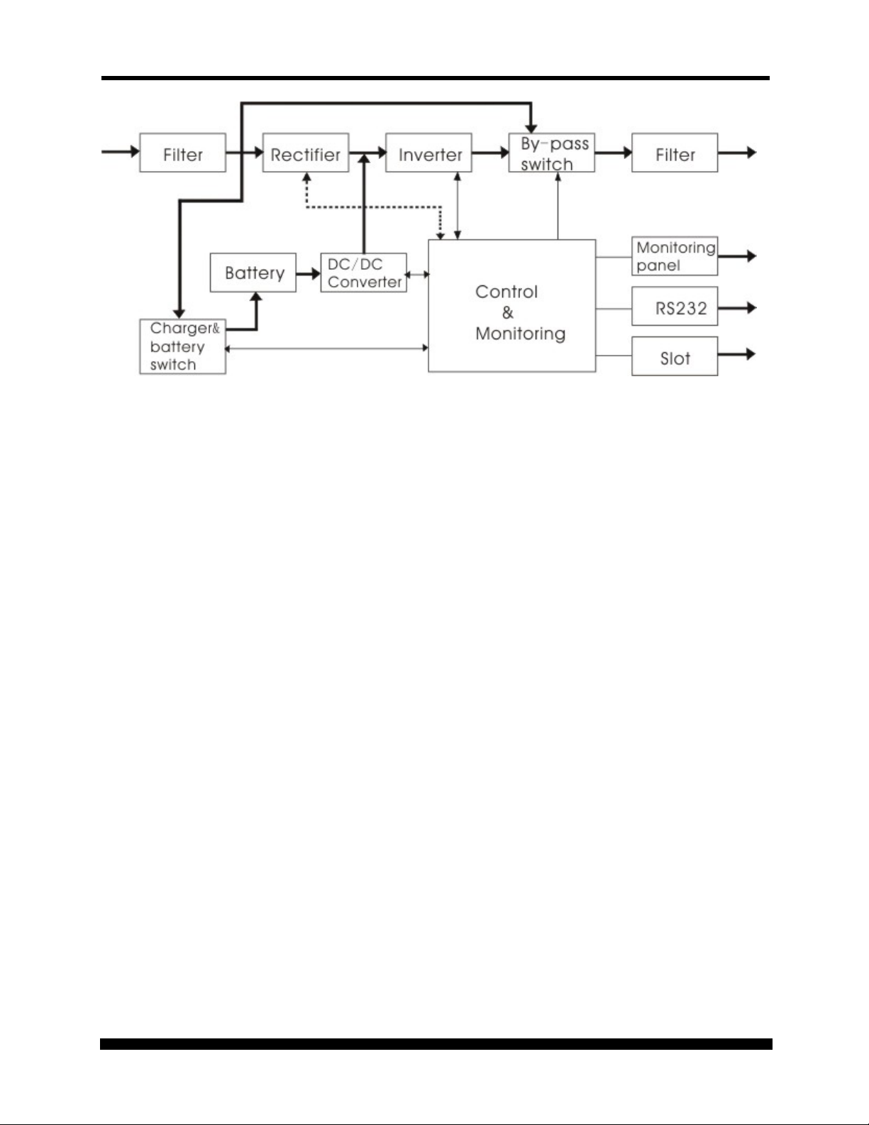
Double Conversion On-Line Technology
A double conversion on-line technology UPS provides completely isolated, clean, uninterrupted singlephase power to your critical systems, while maintaining the batteries for their maximum potential. In
the event that the power failure lasts longer than the UPS backup time, the UPS will shut down avoiding
battery damage. When the input AC voltage returns, the UPS will automatically return online to
recharge the batteries.
As shown in block diagram:
• An input filter reduces transients on the incoming utility.
• To maintain full battery charge, the AC input power is rectified and regulated in the rectifier
feeding power to the battery converter and inverter.
• DC power is converted to AC in the inverter, passing it on to the load.
• Power is maintained from the battery during a power failure.
• The converter increases voltage appropriately for the inverter.
Xtreme Power Conversion Corporation (Rev 8/29/13) Page 7
Page 8
P90 USER’S MANUAL UNINTERRUPTIBLE POWER SUPPLY (UPS)
Block Diagram
Diagnostic Tests
When the UPS is started, a diagnostic test is automatically executed, checking the electronics and
batteries, reporting any problems on the LCD display.
SYSTEM CONFIGURATION
The UPS device and the internal batteries make up the system. Depending on the site and load
requirements of the installation, certain additional options are available for the solution.
Planning a UPS system, the following should be taken into consideration:
• The total demand of the protected system shall dictate the output power rating (VA). Allow a
margin for future expansion or calculation inaccuracies from measured power requirements.
• Backup time required will indicate the battery size needed. If the load is less than the UPS
nominal power rating, then actual backup time is longer.
• The following options are available:
o Connectivity Options –SNMP/WEB card
See the Specification section of this manual for additional model information.
Xtreme Power Conversion Corporation (Rev 8/29/13) Page 8
Page 9
P90 USER’S MANUAL UNINTERRUPTIBLE POWER SUPPLY (UPS)
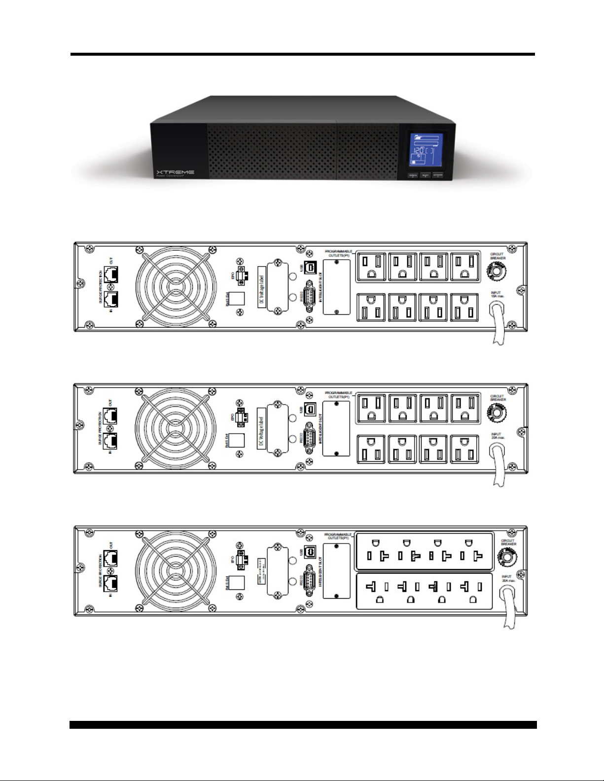
FRONT VIEW PICTURE
P90-1000 REAR VIEW DIAGRAM
P90-1500 REAR VIEW DIAGRAM
P90-2000 REAR VIEW DIAGRAM
Xtreme Power Conversion Corporation (Rev 8/29/13) Page 9
Page 10
P90 USER’S MANUAL UNINTERRUPTIBLE POWER SUPPLY (UPS)
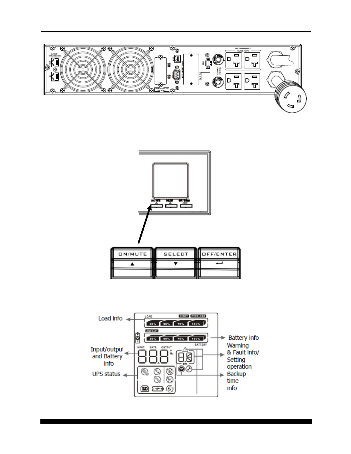
P90-3000 REAR VIEW DIAGRAM
FRONT PANEL
SELECTOR BUTTONS
Xtreme Power Conversion Corporation (Rev 8/29/13) Page 10
Page 11
P90 USER’S MANUAL UNINTERRUPTIBLE POWER SUPPLY (UPS)
RACK DISPLAY
TOWER DISPLAY
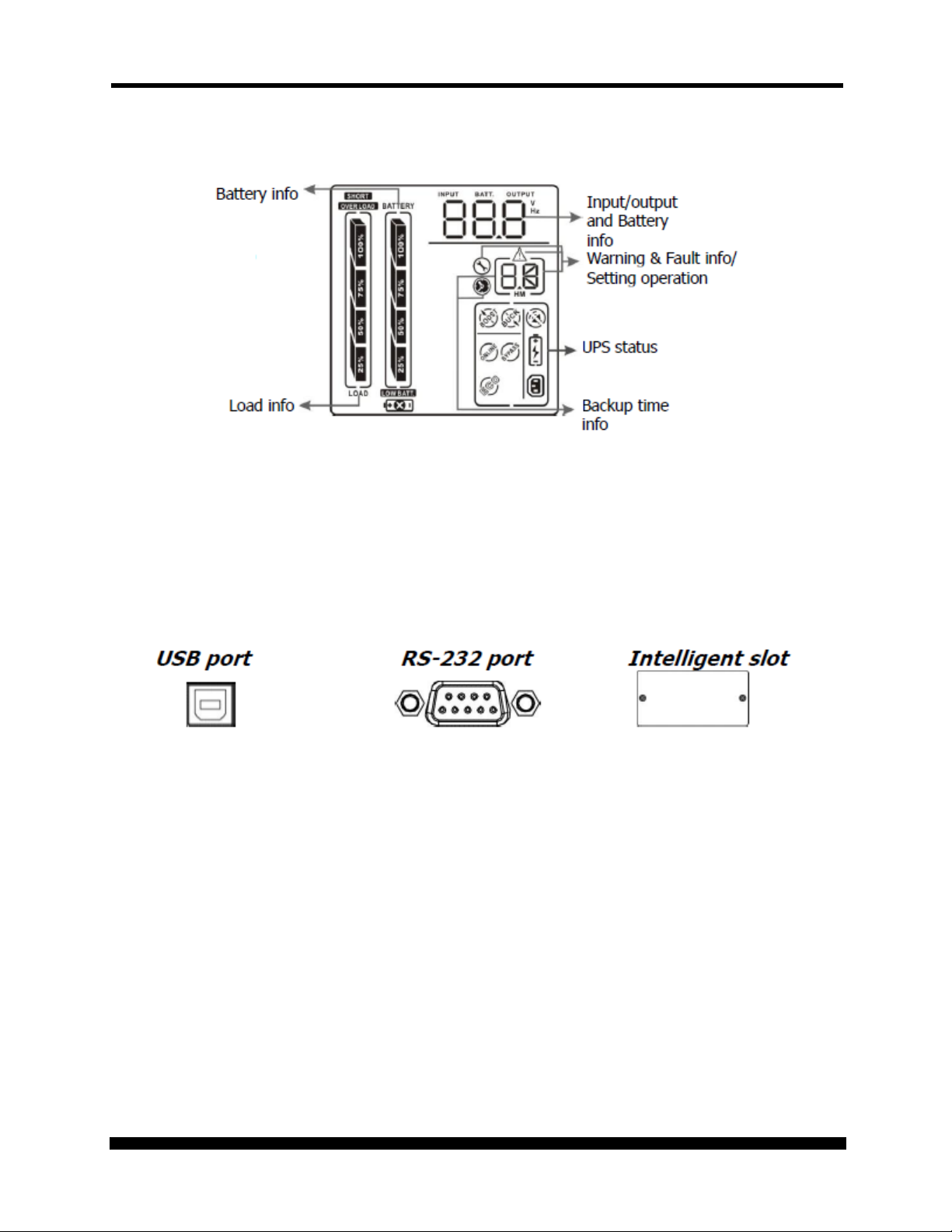
Communication Connections
To allow for unattended UPS shutdown/start-up and status monitoring, connect one end of the
communication cable to the USB/RS232 port and the other to the communications port on your PC or
server. With the monitoring software installed, the UPS can be scheduled for shutdown/start-up and
monitoring of the UPS status through the PC or server.
Xtreme Power Conversion Corporation (Rev 8/29/13) Page 11
Page 12

P90 USER’S MANUAL UNINTERRUPTIBLE POWER SUPPLY (UPS)
PIN #
FUNCTIONS
1,4,6,7,8,9
Reserved
2
UPS transmit
3
UPS receive
5
Ground
RS232 Communications
The RS-232 interface uses a 9-pin female D-sub connector. Information provided includes data about
utility, load and the UPS. The interface port pins and their functions are identified in the following table:
SNMP Communications Option
The UPS provides an intelligent slot for internal or external network card. This special intelligent network
card can be compatible with popular software and hardware found on the web and in operating
systems. It can support operating systems such as HP Open View, IBM Netview, SUN Netmanager, etc.
This enables the UPS to provide instant UPS and power information over the network. Please contact
your reseller for additional details.
Emergency Power Off (EPO) Port
A customer supplied switch located remotely can be used to close the EPO connection and allows the
UPS output receptacles to be switched off. Since the EPO shuts down the equipment immediately,
orderly shutdown procedures are not followed by any power management software. The UPS will have
to be manually restarted in order to regain power to the outlets on the UPS.
Keep Pin 1 and Pin 2 closed for UPS normal operation. To activate EPO function, cut the wire between
Pin 1 and Pin 2.
Xtreme Power Conversion Corporation (Rev 8/29/13) Page 12
Page 13

P90 USER’S MANUAL UNINTERRUPTIBLE POWER SUPPLY (UPS)
HARDWARE INSTALLATION GUIDE
Inspect the UPS upon receipt. The packaging is recyclable; keep it for reuse or dispose of properly.
Safety Information
Information presented here is vital to all personnel. Please read all Safety information.
Storage and Transportation
Please handle the UPS and associated equipment with extreme caution since a high amount of energy is
contained in the batteries. Always keep the unit in an upright position as marked on the packaging, and
never drop the unit.
Please adhere to the following instructions if the UPS is not installed immediately:
• Store the equipment as is in its original packing and shipping carton.
• Do not store in temperatures outside the range of -15°C to +25°C
• Ensure that the equipment is fully protected from wet or damp areas and from moist air.
In order to maintain the batteries, the UPS should be recharged every 6 months for at least 8 hours.
If flammable substances such as gases or fumes are present, or if the room is airtight, a hazardous
situation may exist in which no electrical equipment should be operated.
The instructions in this manual explain how to install the UPS safely. Not acknowledging such electrical
hazards may be fatal – keep this manual for future reference.
WARNING!
It is strongly recommended that the UPS cabinet not be opened as components have very
high voltage and touching those components may be fatal. Only a qualified technician or
authorized agent may service the unit.
The UPS unit’s output receptacles carry live voltage even when not connected to an input
voltage source. The UPS has its own internal energy source.
Xtreme Power Conversion Corporation (Rev 8/29/13) Page 13
Page 14
P90 USER’S MANUAL UNINTERRUPTIBLE POWER SUPPLY (UPS)
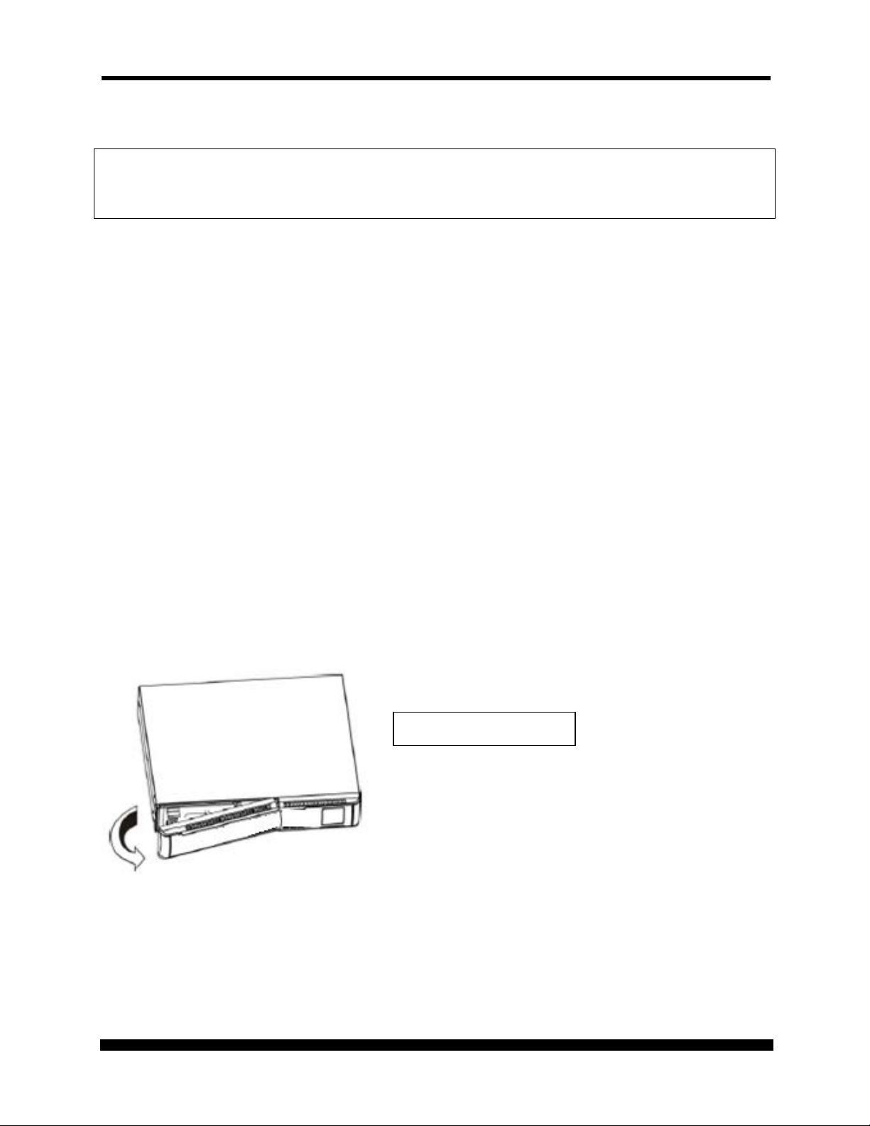
Remove the front panel
Environment
Ensure that all environmental concerns and requirements are met according to specifications listed in
this document, otherwise the safety of installation personnel cannot be guaranteed, and the unit may
malfunction.
Ensure that you remember the following when locating the UPS system and battery options:
• Avoid extremes of temperature and humidity. Maximum battery life can be attained with a
recommended temperature range of +15°C to +25°C.
• Provide protection for the equipment from moisture.
• Space and ventilation requirements must be met. Ensure there is 100mm behind and 50mm on
the sides of the UPS for proper ventilation.
• Ensure that the front of the UPS remains clear for user operation.
UPS Installation
Installation and wiring must be performed in accordance with the local electrical laws and regulations,
and performed by appropriate personnel.
For safety considerations, the UPS is shipped from the factory without connecting the battery wires.
Before installing the UPS, please follow these steps for connection of the battery wires.
Connecting the batteries
Step 1
Xtreme Power Conversion Corporation (Rev 8/29/13) Page 14
Page 15
P90 USER’S MANUAL UNINTERRUPTIBLE POWER SUPPLY (UPS)
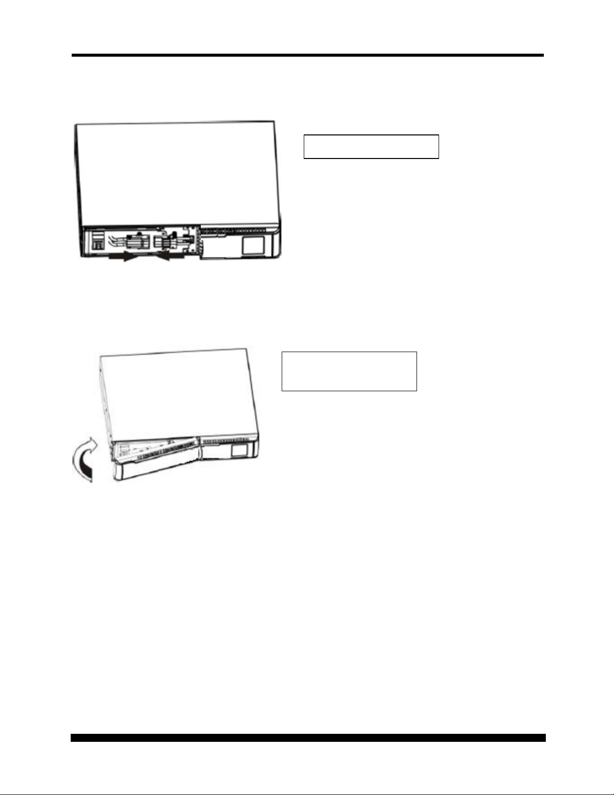
Connect the battery wires
Place the front cover back
Step 2
Step 3
on the front of the UPS
Xtreme Power Conversion Corporation (Rev 8/29/13) Page 15
Page 16

P90 USER’S MANUAL UNINTERRUPTIBLE POWER SUPPLY (UPS)
Attach brackets to the
Slide the UPS into the rack
Rack-mount Installation (using front brackets)
Step 1
front corners of the UPS
Step 2
and secure using
hardware provided
Xtreme Power Conversion Corporation (Rev 8/29/13) Page 16
Page 17

P90 USER’S MANUAL UNINTERRUPTIBLE POWER SUPPLY (UPS)
Rack-mount Installation (using 4-post rail kit)
Package contents
• Right and left rail sliders, 1 each
• (2) M6 nuts
• (12) M6 screws
Step 1
Use 4 screws to mount right and left rail sliders in front of rack.
Xtreme Power Conversion Corporation (Rev 8/29/13) Page 17
Page 18

P90 USER’S MANUAL UNINTERRUPTIBLE POWER SUPPLY (UPS)
Step 2
Use 4 screws to mount right and left rail sliders in back of rack.
Step 3
Place the nuts in the proper location in the rack based upon height of UPS.
Xtreme Power Conversion Corporation (Rev 8/29/13) Page 18
Page 19

P90 USER’S MANUAL UNINTERRUPTIBLE POWER SUPPLY (UPS)
Step 4
Carefully place the UPS on the rail support.
Step 5
Fix the UPS in position with screws.
Step 6
Rail kit installation is now complete.
Xtreme Power Conversion Corporation (Rev 8/29/13) Page 19
Page 20

P90 USER’S MANUAL UNINTERRUPTIBLE POWER SUPPLY (UPS)
Inter-connect the tower
Carefully lower the UPS
Tower Installation
Step 1
brackets that shipped in
the box with the UPS
Step 2
into the brackets as
shown
Xtreme Power Conversion Corporation (Rev 8/29/13) Page 20
Page 21

P90 USER’S MANUAL UNINTERRUPTIBLE POWER SUPPLY (UPS)
Your UPS is now mounted
Step 3
as shown in the tower
position
UPS Input Connection
Connect the UPS to an approved electrical input source consistent with the input power cord connection
provided with the UPS. Do not replace the power cord or use a substitute. Avoid using extension cords
when connecting AC input to any UPS.
UPS Output
There are two types of output on the P90-1000, P90-1500, and P90-2000 models - programmable
outlets and general outlets. Please connect non-critical devices to the programmable outlets and critical
devices to the general outlets. During power failure, you may extend the backup time to critical devices
by setting shorter backup time for non-critical devices.
Programmable outlets can also be used to re-cycle the power to remote devices if required to re-start a
server due to lock-up issues.
Starting the UPS
Press the ON/MUTE button on the front panel of the UPS for two seconds to power on the UPS.
Note: the battery charges during the first five hours of normal operation. Do not expect full battery run
time during the initial charge period.
Xtreme Power Conversion Corporation (Rev 8/29/13) Page 21
Page 22

P90 USER’S MANUAL UNINTERRUPTIBLE POWER SUPPLY (UPS)
Remove the front panel
Software Installation
For optimal system protection, install UPS monitoring software to fully configure UPS shutdown. Please
follow steps below to download and install monitoring software, or simply install via the included CD:
1. Got to the website
2. Click ViewPower software icon and then choose your required Operating System to download
the software.
3. Follow the on-screen instructions to install the software.
4. When your computer restarts, the monitoring software will appear as an orange plug icon
located in the system tray near the clock.
http://www.power-software-download.com
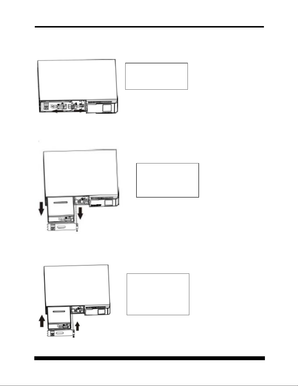
Battery Replacement
NOTICE: The UPS is equipped with internal batteries. The batteries can be replaced without shutting the
UPS down as these are hot-swappable battery trays. Replacement is a safe procedure, isolated from
electrical hazards.
CAUTION: Consider all Safety Warnings in previous sections of this manual before proceeding with the
battery tray replacement.
NOTE: Please beware that once the battery tray is disconnected from the UPS, the equipment
connected to the output of the UPS is not protected from power outages.
Step 1
Xtreme Power Conversion Corporation (Rev 8/29/13) Page 22
Page 23
P90 USER’S MANUAL UNINTERRUPTIBLE POWER SUPPLY (UPS)
Disconnect the battery
Pull out the battery tray
Slide the new battery
Step 2
tray connector from the
UPS
Step 3
Step 4
by removing the two
screws on the front
panel
tray back to the original
location in the UPS and
secure with the two
screws to the front panel
Xtreme Power Conversion Corporation (Rev 8/29/13) Page 23
Page 24

P90 USER’S MANUAL UNINTERRUPTIBLE POWER SUPPLY (UPS)
Reconnect the battery
Place the front cover back
Step 5
tray connector to the
UPS
Step 6
on the front of the UPS
Xtreme Power Conversion Corporation (Rev 8/29/13) Page 24
Page 25

P90 USER’S MANUAL UNINTERRUPTIBLE POWER SUPPLY (UPS)
Turn on the UPS: Press and hold the button more than 2 seconds to turn on
seconds to enter UPS self-testing while in AC mode.
Turn off the UPS: Press and hold the button more than 2 seconds to turn off
mode.
Switch LCD message: Press this button to change the LCD message for input
mode.
Switch to Bypass mode: When the utility power is normal, press ON/MUTE
out of acceptable range.
OPERATIONS
Button Operation
Button Function
the UPS.
Mute the alarm: After the UPS is turned on in battery mode, press and hold
this button for at least 5 seconds to disable or enable the alarm system. This
ON/MUTE Button
feature will not work when warnings or errors occur.
Up key: Press this button to display the previous selection in UPS setting
mode.
Switch to UPS self-test mode: Press and hold ON/MUTE button for 5
OFF/ENTER Button
SELECT Button
ON/Mute + Select
Button
the UPS. The UPS will be in standby mode under normal power or transfer
to bypass mode if the Bypass enable setting is set by pressing this button.
Confirm selection key: Press this button to confirm selection in UPS setting
voltage, input frequency, battery voltage, output voltage, and output
frequency.
Setting mode: Press and hold this button for 5 seconds to enter the UPS
setting mode when UPS is off.
Down key: Press this button to display the next selection in UPS setting
and SELECT buttons simultaneously for 5 seconds. The UPS will then enter
Bypass mode. The Bypass mode will be disabled when the input voltage is
Xtreme Power Conversion Corporation (Rev 8/29/13) Page 25
Page 26

P90 USER’S MANUAL UNINTERRUPTIBLE POWER SUPPLY (UPS)
Indicates the backup time in pie chart.
Indicates the backup time in numbers.
H: hours, M: minutes
Indicates that the warning and fault occurs.
Indicates the warning fault codes, and the codes are listed in
Indicates the setting operation.
Indicates the output/input voltage, output/input frequency or
Indicates the load level by 0-25%, 26-50%, 51-75%, and 76-100%.
Indicates overload.
Indicates the load or the UPS output is short circuited.
Rack Display
Tower Display
LCD Panel
LCD FRONT PANEL
Display Function
Backup time information
Warning & Fault information
Setting Operation
Input / Output & Battery information
Load information
details in this manual.
battery voltage. V: output voltage, Hz: frequency
Xtreme Power Conversion Corporation (Rev 8/29/13) Page 26
Page 27

P90 USER’S MANUAL UNINTERRUPTIBLE POWER SUPPLY (UPS)
Indicates that programmable management outlets are working.
Indicates the UPS is working in online mode.
Indicates the UPS is working in converter mode.
Indicates the UPS is working in bypass mode.
Indicates the UPS is powering the output directly from utility.
Indicates that the UPS alarm is disabled.
Indicates the battery charger is working.
Indicates the Battery level by 0-25%, 26-50%, 51-75%, and 76-
Indicates low battery.
Indicates there is something wrong with the battery.
Description
Buzzer status
Battery Mode
Sounds every 4 seconds
Low Battery
Sounds every second
Overload
Sounding twice every second
Fault
Continuously sounds
Display Function
UPS Status
Battery information
Audible Alarms:
100%.
Xtreme Power Conversion Corporation (Rev 8/29/13) Page 27
Page 28

P90 USER’S MANUAL UNINTERRUPTIBLE POWER SUPPLY (UPS)
Abbreviation
Display
Meaning
Abbreviations in LCD Display
ENA
DIS
ESC
RAC
TOE
B.L
O.L
N.C
O.C
S.F
Enable
Disable
Escape
Rack Display
Tower Display
Low Battery
Overload
Battery is not connected
Overcharge
Site Fault
E.P
T.P
C.H
B.B
F.U
B.V
EPO
Over Temperature
Charger Failure
Battery Fault
Frequency Unstable in Bypass
Mode
Input Voltage is Out of Bypass
Range
Xtreme Power Conversion Corporation (Rev 8/29/13) Page 28
Page 29

P90 USER’S MANUAL UNINTERRUPTIBLE POWER SUPPLY (UPS)
Interface
Setting
Interface
Setting
There are two parameters to set up the UPS.
UPS Setting
Parameter 1: for program alternatives –
there are 9 programs to set up.
Parameter 2: for setting information display.
01: Output Voltage Settings
You may choose the following output voltage:
110: presents output voltage as 110VAC
115: presents output voltage as 115VAC
120: presents output voltage as 120VAC
127: presents output voltage as 127VAC
02: Frequency Converter enable/disable
CF ENA: converter mode enable
CF DIS: converter mode disable
Xtreme Power Conversion Corporation (Rev 8/29/13) Page 29
Page 30

P90 USER’S MANUAL UNINTERRUPTIBLE POWER SUPPLY (UPS)
Interface
Setting
Interface
Setting
Interface
Setting
03: Output Frequency Setting
You may set the initial frequency on battery mode:
BAT 50: presents output frequency at 50Hz
BAT 60: presents output frequency is 60Hz
If converter mode is enabled, you may choose the following
output frequency:
CF 50: presents output frequency at 50Hz
CF 60: presents output frequency at 60Hz
04: ECO enable/disable
05: AECO enable/disable
ENA: ECO mode enable
DIS: ECO mode disable
ENA: Advanced ECO mode enable
DIS: Advanced ECO mode disable
Xtreme Power Conversion Corporation (Rev 8/29/13) Page 30
Page 31
P90 USER’S MANUAL UNINTERRUPTIBLE POWER SUPPLY (UPS)
Interface
Setting
Interface
Setting
Interface
Setting
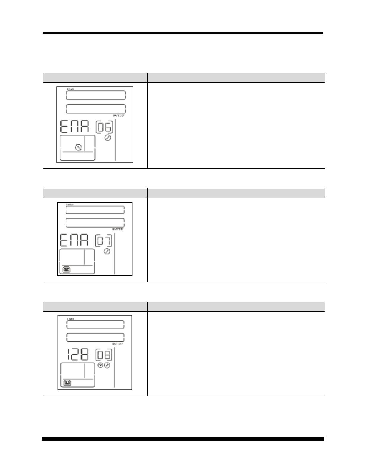
06: Bypass Mode enable/disable
ENA: Bypass mode enable
DIS: Bypass mode disable
07: Programmable Outlets enable/disable
ENA: Programmable outlets enable
DIS: Programmable outlets disable
08: Programmable Outlets Setting
0-999: setting the backup time limits in minutes from 0-999 for
programmable outlets connected to non-critical devices
when operating in battery mode.
Xtreme Power Conversion Corporation (Rev 8/29/13) Page 31
Page 32

P90 USER’S MANUAL UNINTERRUPTIBLE POWER SUPPLY (UPS)
Interface
Setting
Interface
Setting
09: LCD Display Direction Setting
RAC: the LCD display is horizontal.
TOE: the LCD display is vertical.
10: Acceptable Input Voltage Range Settin
00: Exit Setting
Choose the following Acceptable input voltage range:
55/150 alternating flashing: acceptable input voltage range is
from 55V to 150V
80/130 alternating flashing: acceptable input voltage range is
from 80V to 130V
85/135 alternating flashing: acceptable input voltage range is
from 85V to 135V
Xtreme Power Conversion Corporation (Rev 8/29/13) Page 32
Page 33

P90 USER’S MANUAL UNINTERRUPTIBLE POWER SUPPLY (UPS)
Operating
LCD Display
Rack Display
Tower Display
Operating Mode Description
Mode
Online Mode When the input voltage is within
ECO Mode
(Efficiency
Corrective
Optimizer)
AECO Mode
(Advanced
Efficiency
Corrective
Optimizer)
Description
acceptable range, the UPS will
provide pure and stable AC power
to the output. The UPS will also
charge the battery during Online
Mode.
When the input voltage is within
setting range (± 3% Vo max), UPS
will bypass voltage to output for
energy saving. PFC and INVERTER
are still active in this mode.
When the input voltage is within
setting range (± 3% Vo max), UPS
will bypass voltage to output for
energy saving. PFC and INVERTER
are off in this mode.
Frequency
Converter
Mode (Rack)
Xtreme Power Conversion Corporation (Rev 8/29/13) Page 33
When input frequency is within 40
Hz to 70 Hz, the UPS can be set at
a constant output frequency, 50 Hz
or 60 Hz. The UPS will still change
battery in this mode.
Page 34

P90 USER’S MANUAL UNINTERRUPTIBLE POWER SUPPLY (UPS)
Operating
LCD Display
Rack Display
Tower Display
Mode
Description
Battery Mode When the input voltage is beyond
the acceptable range or there is a
power failure and alarm is
sounding every 4 seconds, the UPS
will provide backup power from
battery.
Bypass Mode When input voltage is within
acceptable range but UPS is
overloaded, the UPS will enter
bypass mode or bypass mode can
be set by the front panel. Alarm is
sounding every 10 seconds.
Standby Mode UPS is powered off without output
power, but the battery is still being
charged.
Fault Mode The UPS is in fault mode when no
output power is supplied from the
UPS and the fault icon flashes on
the LCD display, although the
information from the UPS can be
displayed on the screen.
Xtreme Power Conversion Corporation (Rev 8/29/13) Page 34
Page 35

P90 USER’S MANUAL UNINTERRUPTIBLE POWER SUPPLY (UPS)
Fault
Fault
Bus start failure
01
X
Inverter output short
14
Bus over
02
X
Battery voltage too high
27
X
Bus under
03
X
Battery voltage too low
28
Bus unbalanced
04
X
Over temperature
41
X
Inverter soft start fail
11
X
Overload
43
High Inverter voltage
12
X Low Inverter voltage
13
X
Fault Reference Codes
Fault event
code Icon Fault event
code Icon
Xtreme Power Conversion Corporation (Rev 8/29/13) Page 35
Page 36

P90 USER’S MANUAL UNINTERRUPTIBLE POWER SUPPLY (UPS)
Warning
Icon (flashing)
Code
Alarm
Warning Indicators
Low battery
Overload
Battery not connected
Overcharge
Site wiring fault
EPO enable
Over temperature
Charger failure
Sounds every second
Sounds twice every second
Sounds every second
Sounds every second
Sounds every second
Sounds every second
Sounds every second
Sounds every second
Battery fault
Bypass Out of Range
Bypass Frequency
Unstable
Xtreme Power Conversion Corporation (Rev 8/29/13) Page 36
Sounds every second
Sounds every second
Sounds every second
Page 37

P90 USER’S MANUAL UNINTERRUPTIBLE POWER SUPPLY (UPS)
Symptom
Possible cause
Remedy
The AC input power is not
Check if input power cord is
firmly connected to the
The AC input is connected to
Plug the AC input power cord
into the AC input utility
position to disable EPO
Line and neutral conductors
Have a qualified electrician
correct the input receptacle
The internal battery is
Check to make sure all
e properly
Fault cod is shown as 27 and the icon
the charger is in fault
Contact your dealer for
Fault cod is shown as 28 and the icon
the charger is in fault
Contact your dealer for
TROUBLESHOOTING
If the UPS does not operate correctly, please use the table below to troubleshoot the problems.
No indication and alarm even though
the utility is normal.
The icon and the warning code
flash on LCD display and alarm
sounding every second.
The icon and are flashing
on LCD display and alarm is sounding
every second.
The icon and are
flashing on LCD display and alarm is
sounding every second
is showing on LCD display and
alarm is continuously sounding.
connected well.
the UPS output.
EPO function is enabled.
of UPS input are reversed.
incorrectly connected.
Battery voltage is too high or
condition.
utility.
correctly.
Set the circuit to the closed
function.
wiring.
batteries ar
connected.
support.
is showing on LCD display and
alarm is continuously sounding.
Xtreme Power Conversion Corporation (Rev 8/29/13) Page 37
Battery voltage is too low or
condition.
support.
Page 38

P90 USER’S MANUAL UNINTERRUPTIBLE POWER SUPPLY (UPS)
Symptom
Possible cause
Remedy
Remove excess loads from
UPS is in overload. Devices
connected to the UPS are
being fed directly from the
electrical utility via the
Remove excess loads from
After repetitive overloads,
the UPS is locked in the
Bypass mode. Connected
Remove excess loads from
Fault code is shown as 43 and the
display and alarm is sounding
The UPS shut down
overload condition on the
Remove excess loads from
the UPS output and restart
The UPS shut down
automatically because short
circuit occurs on the UPS
Check output wiring and if
connected devices are in
Fault code is shown as 01, 02, 03, 04,
A UPS internal fault has
occurred. There are two
The load is still
by AC utility via
Contact your dealer for
Batteries are not fully
Charge the batteries for at
still exists, contact your
Contact your dealer for
The icon and are
flashing on LCD display and alarm is
sounding twice every second.
icon is showing on LCD
continuously.
Fault code is shown as 14 and alarm
is sounding continuously.
UPS is in overload.
Bypass
devices are being fed directly
by the electrical utility.
automatically because of the
UPS output.
output.
UPS output.
UPS output.
UPS output, then shut down
the UPS and restart.
the UPS.
short circuit status.
11, 12, 13 and 41 on LCD display and
alarm is sounding continuously.
Battery backup time is shorter than
expected.
Xtreme Power Conversion Corporation (Rev 8/29/13) Page 38
possible results:
1.
supplied, but directly
bypass.
2. The load is no longer
supplied with power.
charged.
Batteries are defective.
support.
least 5 hours and then recheck capacity. If the problem
dealer for support.
battery replacement.
Page 39

P90 USER’S MANUAL UNINTERRUPTIBLE POWER SUPPLY (UPS)
Storage Temperature
Recharge Frequency
Charging Duration
-25°C - 40°C
Every 3 months
1-2 hours
40°C - 45°C
Every 2 months
1-2 hours
STORAGE AND MAINTENANCE
Storage
Before storing, charge the UPS at least 5 hours. Store the UPS covered and upright in a cool, dry
location. During storage, recharge the battery in accordance with the following table:
Xtreme Power Conversion Corporation (Rev 8/29/13) Page 39
Page 40

P90 USER’S MANUAL UNINTERRUPTIBLE POWER SUPPLY (UPS)
Maintenance
The UPS system operates with hazardous voltages. Repairs may be carried out only by qualified
maintenance personnel.
Even after the unit is disconnected from the mains, components inside the UPS system are still
connected to the battery packs which are potentially dangerous.
Before carrying out any kind of service and/or maintenance, disconnect the batteries and
verify that no current is present and no hazardous voltage exists in the terminals of high
capability capacitor such as BUS-capacitors.
Only persons are adequately familiar with batteries and with the required precautionary
measures may replace batteries and supervise operations. Unauthorized persons must be kept
well away from the batteries.
Verify that no voltage between the battery terminals and the ground is present before
maintenance or repair. In this product, the battery circuit is not isolated from the input
voltage. Hazardous voltages may occur between the battery terminals and the ground.
Batteries may cause electric shock and have a high short-circuit current. Please remove all
wristwatches, rings and other metal personal objects before maintenance or repair, and only
use tools with insulated grips and handles for maintaining or repairing.
When replace the batteries, install the same number and same type of batteries.
Do not attempt to dispose of batteries by burning them. This could cause battery explosion.
The batteries must be rightly deposed according to local regulation.
Do not open or destroy batteries. Escaping electrolyte can cause injury to the skin and eyes. It
may be toxic.
Please replace the fuse only with the same type and amperage in order to avoid fire hazards.
Do not disassemble the UPS system.
The UPS contains no user-serviceable parts.
Xtreme Power Conversion Corporation (Rev 8/29/13) Page 40
Page 41

P90 USER’S MANUAL UNINTERRUPTIBLE POWER SUPPLY (UPS)
BATTERIES
The life of batteries used in these UPS products is estimated at 3-6 years depending on level of usage.
Once the battery is no longer useful and must be replaced, please contact service personnel for
assistance.
REPLACING THE BATTERY
(QUALIFIED SERVICE PERSONNEL ONLY)
CAUTION! Read and follow the IMPORTANT SAFETY INSTRUCTIONS before servicing the battery.
Service the battery under the supervision of Qualified Service Personnel knowledgeable of batteries and
their precautions.
CAUTION! Use only the specified type of battery. See your dealer for replacement batteries.
CAUTION! The battery may present risk of electrical shock. Do not dispose of batteries in a fire as it
may explode. Follow all local ordinances regarding proper disposal of batteries.
CAUTION! Do not open or mutilate the batteries. Released electrolyte is harmful to skin and eyes
and may be toxic.
CAUTION! The battery can present a high risk of short circuit current and electrical shock. The short
circuit current capability of the battery is sufficient to burn wire or tools very rapidly, producing molten
metal. Observe these precautions when replacing the battery:
1. Remove all watches, rings or other metal objects.
2. Only use tools with insulated handles.
3. Do not lay tools or metal parts on top of battery or any terminals.
4. Wear protective eye wear (goggles), rubber gloves, and boots.
5. Disconnect the charging source before connecting or disconnecting the battery terminals.
6. Determine if the battery is inadvertently grounded. If inadvertently grounded, remove the
source of the ground. Contact with a grounded battery can result in electrical shock! The
likelihood of such shock will be reduced if such grounds are removed during installation and
maintenance (applicable to a UPS and a remote battery supply not having a grounded circuit).
Xtreme Power Conversion Corporation (Rev 8/29/13) Page 41
Page 42

P90 USER’S MANUAL UNINTERRUPTIBLE POWER SUPPLY (UPS)
1000 VA
(900 W)
1500 VA
(1350 W)
2000 VA
(1800 W)
3000 VA
(2700 W)
120 VAC ± 1% battery mode (adjustable to
100/110/115/120VAC)
(2) 12V 9AH
/ 24V
(3) 12V 9AH /
36V
(4) 12V 9AH
/ 48V
(6) 12V 9AH
/ 72V
SPECIFICATIONS
120V MODEL P90-1000 P90-1500 P90-2000 P90-3000
INPUT
OUTPUT
Voltage 120 VAC (85-150V) @ full load
Capacity VA (W)
Frequency 40 - 70 Hz
Power Factor ≥ 0.99 @ normal voltage @ full load
Topology Online
ECO Mode Increases efficiency to 98%
EPO Normally closed
Voltage
Frequency 57 - 63 Hz
THD (full load) ≤ 2% linear load (8% max battery mode before shutdown)
Wave form Sine wave, 0 ms transfer time
Load Power Factor 0.9
Efficiency 86-88% (AC mode); 83-85% (Battery mode)
Auto Restart Yes
Start on Battery Yes
BATTERY
Rated Current 8.3A 12.5A 16.67A 25.0A
Overload Capacity 125% for 2 min; 150% for 10 sec; > 150% 1 sec
Crest Factor 5:1 at full load
Battery Type
sealed maintenance-free in hot-swappable trays
Backup Time 3 min 45 sec 4 min 41 sec 3 min 50 sec 4 min 15 sec
Charge Current 1A
Recharge Time < 4 hours to 90%
Xtreme Power Conversion Corporation (Rev 8/29/13) Page 42
Page 43

P90 USER’S MANUAL UNINTERRUPTIBLE POWER SUPPLY (UPS)
17.24 x 14.96
88 mm)
17.24 x 23.62
88 mm)
29.1 lbs
(13.2 kg)
41.67 lbs
(18.9 kg)
45.42 lbs
(47.29 kg)
65.7 lbs
(29.8 kg)
Line Cord
6 ft (1.8 m)
Receptacles
load segment)
Network
Protection
Communication
Interface
RS-232 and USB with Intelligent slot for
Web/SNMP (optional card) or AS400 (optional card)
ViewPower CD, horizontal brackets (front),
tower stand brackets, 4-post rail kit, 4ft USB cable, manual
Programmable / Rotatable Display with Input / Output
capacity, Load level
Low battery, Overload, Battery not connected, Overcharge,
Charger failure, Battery fault
120V MODEL P90-1000 P90-1500 P90-2000 P90-3000
PHYSICAL
ENVIRONMENTAL
Dimensions
W x D x H
x 3.5 in
(438 x 380 x
17.24 x 18.9 x 3.5 in
(438 x 480 x 88 mm)
Unit Weight
5-15P 5-20P L5-30P
(with Programmable
(8) 5-15/20R
Modem / phone / fax / network in/out for surge protection
Included in Box
Temperature
32-104°F (0 - 40°C)
Humidity 0 – 95% Non-Condensing
Audible Noise < 45dba @ 1 meter
Altitude 11,500 ft (3500 m) above sea level
x 3.5 in
(438 x 600 x
(1) L5-30R +
(4) 5-15/20R
Warranty Three years electronics / Three years batteries
Approvals UL 1778, cUL, FCC
Indicators &
Alarms
LCD Visual Display
Voltage & Frequency, Online mode, Backup mode, Battery
Buttons On / Mute; Select; Off / Enter
Audible Alarm
Site wiring fault, EPO mode, Fan failure, Over temperature,
Xtreme Power Conversion Corporation (Rev 8/29/13) Page 43
Page 44

P90 USER’S MANUAL UNINTERRUPTIBLE POWER SUPPLY (UPS)
SHIPPING LIST
1.
ViewPower CD
2.
horizontal brackets (front)
3.
tower stand brackets
4-post rail kit
4.
5.
manual
6.
4ft USB cable
Xtreme Power Conversion Corporation (Rev 8/29/13) Page 44
Page 45

P90 USER’S MANUAL UNINTERRUPTIBLE POWER SUPPLY (UPS)
OBTAINING SERVICE
If the UPS requires Service:
1. Use the TROUBLESHOOTING section in this manual to eliminate obvious causes.
2. Verify there are no circuit breakers tripped.
3. Call your dealer for assistance. If you cannot reach your dealer, or if they cannot resolve the
problem, call Xtreme Power Conversion Corp Technical Support at 800.582.4524 or
720.292.1217. Technical support inquires can also be made at
the following information available BEFORE calling the Technical Support Department:
a. Your name and address.
b. The serial number of the unit.
c. Where and when the unit was purchased.
d. All of the model information about your UPS.
e. Any information on the failure, including LED’s that may or may not be illuminated.
f. A description of the protected equipment, including model numbers if possible.
A technician will ask you for the above information and, if possible, help solve your problem
over the phone. In the event that the unit requires factory service, the technician will issue you a
Return Material Authorization number (RMA).
support@xpcc.com. Please have
If you are returning the UPS to Xtreme Power for service, please follow these procedures:
1. Pack the UPS in its original packaging. If the original packaging is no longer available, as
the Technical Support Technician about obtaining a replacement set of packaging
material. It is important to pack the UPS properly in order to avoid damage in transit.
Never use Styrofoam beads for a packing material.
2. Include a letter with your name, address, daytime phone number, RMA number, a copy
of your original sales receipt, and a brief description of the problem.
3. Mark the RMA number on the outside of all packages. Xtreme Power cannot accept any
package without the RMA number marked on the outside of the boxes.
4. Return the UPS by insured, prepaid carrier to the address provided by the Technician.
Refer to the Warranty statements in this manual for additional details on what is covered.
Xtreme Power Conversion Corporation (Rev 8/29/13) Page 45
Page 46

P90 USER’S MANUAL UNINTERRUPTIBLE POWER SUPPLY (UPS)
XTREME POWER CONVERSION CORPORATION LIMITED WARRANTY
Xtreme Power Conversion (XPC) Corporation warrants Xtreme Power Conversion equipment, when
properly applied and operated within specified conditions, against faulty materials or workmanship
(excluding batteries) for a period of three years for P90-Series products from the date of purchase. XPC
Corporation warrants internal batteries for a period of three years from the date of purchase. For
equipment sites within the United States and Canada, this warranty covers repair or replacement, at the
sole discretion of XPC Corporation. The customer is responsible for the costs of shipping the defective
product to XPC Corporation. XPC Corporation will pay for ground shipment of the repaired or
replacement product. This warranty applies only to the original purchaser.
If equipment provided by XPC Corporation is found to be Dead-on-Arrival (DOA), XPC Corporation will
be responsible for the costs of shipping product to and returning equipment from the customer in a
timely manner as agreed to with the customer, once the customer has requested and received a Return
Material Authorization (RMA) number. DOA equipment is defined as equipment that does not properly
function according to user documentation when initially received and connected in conjunction with
proper procedures as shown in the user documentation or via support provided by XPC Corporation
personnel or authorized agents.
This warranty shall be void if (a) the equipment is repaired or modified by anyone other than XPC
Corporation or a XPC Corporation approved third party; (b) the equipment is damaged by the customer,
is improperly used or stored, is subjected to an adverse operating environment, or is operated outside
the limits of its electrical specifications; or (c) the equipment has been used or stored in a manner
contrary to the equipment’s operating manual, intended use or other written instructions. Any technical
advice furnished by XPC Corporation or a XPC Corporation authorized representative before or after
delivery with regard to the use or application of Xtreme Power Conversion equipment is furnished on
the basis that it represents XPC Corporations best judgment under the situation and circumstances, but
it is used at the recipient’s sole risk.
EXCEPT AS STATED ABOVE, XPC Corporation DISCLAIMS ALL WARRANTIES, EXPRESSED OR IMPLIED,
INCLUDING WARRANTIES OF MERCHANTABILITY AND FITNESS FOR A PARTICULAR PURPOSE.
EXCEPT AS STATED ABOVE, IN NO EVENT WILL XPC Corporation BE LIABLE FOR DIRECT, INDIRECT,
SPECIAL, INCIDENTAL, OR CONSEQUENTIAL DAMAGES ARISING OUT OF THE USE OF Xtreme Power
Conversion EQUIPMENT, including but not limited to, any costs, lost profits or revenue, loss of
equipment, loss of use of equipment, loss of software, loss of data, cost of substitutes, or claims by third
parties..Purchaser’s sole and exclusive remedy for breach of any warranty, expressed or implied,
concerning Xtreme Power Conversion equipment, and the only obligation of XPC Corporation under this
warranty, shall be the repair or replacement of defective equipment, components, or parts; or, at XPC
Corporations sole discretion, refund of the purchase price or substitution of an equivalent replacement
product.
Xtreme Power Conversion Corporation (Rev 8/29/13) Page 46
Page 47

P90 USER’S MANUAL UNINTERRUPTIBLE POWER SUPPLY (UPS)
XTREME POWER CONVERSION LOAD PROTECTION POLICY
THIS POLICY IS NOT A WARRANTY. REFER TO THE XPC CORPORATION, INC. LIMITED WARRANTY FOR INFORMATION CONCERNING THE
WARRANTY FOR YOUR XPC PRODUCT. THE LIMITATIONS AND CONDITIONS CONTAINED IN THIS POLICY DO NOT AFFECT THE TERMS OF THE
XPC LIMITED WARRANTY.
Definitions:
1. “Product” means a Standard 120, 208, or 240 Volt power protection device that is used in the United States and Canada. This policy
does not include custom manufactured products.
2. “Power Disturbance” means an AC power line transient (telephone line or Local Area Network, if applicable), spike or surge.
3. “Connected Equipment” properly connected electronic equipment
4. “Fair Market Value” of damaged Connected Equipment as determined by XPC shall be the lower of (a) the average price the same or
similar items are being sold for on eBay, (b) the price list of Orion Blue Book (or if such price list is no longer published, a published
or announced price list reasonably selected by XPC), (c) the lowest price the same or similar items can be purchased for in the United
States or (d) the total amount of all payment(s) you have or are entitled to receive from insurance, other warranties, extended
warranties, a legal liability claim or from other sources or persons for the damaged Connected Equipment.
5. “Purchaser” means the person or entity that originally purchased the Product from an authorized reseller or distributor of XPC
Products.
The Purchaser of this Product is protected, for the term of the XPC Limited Warranty, against certain losses caused by a Power Disturbance for
properly connected electronic equipment (referred to as the "Connected Equipment") subject to certain terms and conditions provided below.
This policy applies only to the original purchaser of the Product. If the Product is transferred or sold to another person or entity, this policy is
void.
Load Protection Policy Dollar and Period Limits
For purchasers that meet the qualifications and conditions set forth in this policy, XPC will provide reimbursement (cost of repair or fair market
value as determined by XPC) during the period limits and up to the dollar limits stated as follows:
PRODUCT DOLLAR LIMIT PERIOD OF COVERAGE
XVT 25,000 Term of XPC Limited Warranty
XST 25,000 Term of XPC Limited Warranty
XPRT 6kVA & 10kVA 50,000 Term of XPC Limited Warranty
NXRT 50,000 Term of XPC Limited Warranty
P90, P90L, P90g, P90Lg 50,000 Term of XPC Limited Warranty
T90 50,000 Term of XPC Limited Warranty
TX90, TX90i 50,000 Term of XPC Limited Warranty
This Load Protection Policy is not deemed "first dollar" coverage. XPC’s obligation is reduced by any amounts that the Purchaser is entitled to
recover, from other sources regarding the Connected Equipment, including, but not limited to, insurance, other warranty, extended warranty,
or legal liability, regardless of whether or not the Purchaser makes a claim for recovery.
Eligibility for Coverage Under the Load Protection Policy
1. The Product must be registered on the XPC website, www.xpcc.com, within 10 days of purchase. All required information must be
provided, and Purchaser should retain a copy for Purchaser’s records. When registering on the website, Purchaser must list all
connected equipment that is directly connected to the product. Only those devices registered in that manner will be covered.
2. All Connected Equipment must be UL or CSA approved.
3. The Product must be plugged into a properly wired and grounded outlet. Use of input surge devices, extension cords, adapters,
ground wires, or electrical connections not manufactured by XPC voids the XPC Load Protection Policy. No other surge protection
device may be connected to the output sockets of the Product. The installation must comply with all applicable electrical and safety
codes set forth pursuant to the NEC.
4. The Product must have undeniable physical evidence of a Power Disturbance that directly and proximately caused the damage;
5. The Connected Equipment must have been damaged by a Power Disturbance on a properly installed, grounded, and National
Electric Code, ("NEC"), code-compliant 120, 208, 240 Volt AC power line in the United States or Canada, by a Power Disturbance on
standard telephone land line or PBX telephone equipment line that is properly installed and connected to an RJ11 port on the
Product; or by a Power Disturbance on a standard Local Area Network connection that is properly installed and connected to an RJ45
port on the Product and (d) is directly plugged into, and properly connected to, the Product in its original condition which was
properly operated when a Power Disturbance passed through the Product and (i) exhausts the protection capacity of the Product or
(ii) damages the Product.
6. The Load Protection Policy does not apply if the Product has been operated in a failure mode or not in compliance with XPC
operating instructions in the Product user's manual, or if the Connected Equipment has not been operated in compliance with the
instructions and manuals of its manufacturer/vendor.
7. This policy is null and void if, XPC determines, in its sole discretion, that the Product has been tampered with or altered in any way.
What is Not Covered Under the Load Protection Policy:
Xtreme Power Conversion Corporation (Rev 8/29/13) Page 47
Page 48

P90 USER’S MANUAL UNINTERRUPTIBLE POWER SUPPLY (UPS)
The following damage is not covered by this Policy:
1. Restoration of lost data and reinstallation of software.
2. Damage from a cause other than AC power-line transients, except for damage due to telephone line, Local Area Network, or CATV
transients, which is covered only if the Product offers such protection.
3. DAMAGE CAUSED BY FAILURE TO PROVIDE A SUITABLE INSTALLATION ENVIRONMENT FOR THE PRODUCT (INCLUDING, BUT NOT
LIMITED TO, LACK OF A PROPER SAFETY GROUND).
4. Damage caused by the use of the Product for purposes other than those for which it was designed.
5. Damage caused by accidents, or natural disasters, including but not limited to, fire, flood, and wind.
6. Damage caused by abuse, misuse, alteration, modification, or negligence.
7. Any labor costs or travel, room and board expenses associated with the repair and/or restoration of lost or damaged hardware,
software or data.
EXCEPT AS EXPRESSLY PROVIDED IN THIS POLICY, XPC SHALL NOT BE LIABLE FOR ANY DAMAGES WHATSOEVER,
INCLUDING, BUT NOT LIMITED TO, DIRECT, INDIRECT, SPECIAL, INCIDENTAL, CONSEQUENTIAL, OR MULTIPLE
DAMAGES ARISING OUT OF THE USE OF THE PRODUCT OR DAMAGE TO THE CONNECTED EQUIPMENT,
REGARDLESS OF THE LEGAL THEORY ON WHICH SUCH CLAIM IS BASED, EVEN IF ADVISED OF THE POSSIBILITY OF
SUCH DAMAGE. SUCH DAMAGES INCLUDE, BUT ARE NOT LIMITED TO, LOSS OF PROFITS, LOSS OF SAVINGS OR
REVENUE, LOSS OF USE OF THE PRODUCT OR THE CONNECTED EQUIPMENT OR ANY ASSOCIATED EQUIPMENT,
LOSS OF SOFTWARE, COST OF CAPITAL, COST OF ANY SUBSTITUTE EQUIPMENT, FACILITIES OR SERVICES,
DOWNTIME, THE CLAIMS OF THIRD PARTIES, INCLUDING CUSTOMERS, AND INJURY TO PROPERTY.
Submitting a Load Protection Policy Claim:
1. Any claim under the Load Protection Policy must be made within 10 days of the date of alleged damage to the Connected
Equipment.
2. Call the XPC technical support department at 1-800- 582-4524 and obtain a Load Protection Policy Returned Material Authorization
(RMA) number. Have information on all applicable insurance or other resources of recovery/payment that is available to the
Purchaser and the name of the power utility supplier for the location of the Connected Equipment. XPC will forward to the Purchaser
a Load Protection Policy claims form, which must be completed and filed with XPC within 30 days.
a. Mark the Load Protection Policy RMA number on the Product the Purchaser is returning.
b. Pack the Product in its original packaging or similar packing materials if the original packaging has been discarded. Enclose
the completed Load Protection Policy claim form and a copy of the Purchaser’s original sales receipt for the Product in
the box.
c. Mark the RMA number clearly on the outside of the box.
d. Ship the Product (one-way shipping charges paid by the Purchaser) to:
3. XPC will evaluate the Product to determine its level of functionality, and will examine the Product for evidence of damage from a
Power Disturbance..
a. If XPCs' evaluation provides no evidence of damage from a Power Disturbance, XPC will send to the Purchaser (i) a report
summarizing the tests performed and (ii) a rejection of claim notice.
b. If the Product shows evidence of damage from a Power Disturbance, XPC will request that all Connected Equipment for
which a Load Protection Policy claim has been submitted, be sent for evaluation to either XPC or an authorized service
center. If it is determined that the Connected Equipment has been damaged by a Power Disturbance, XPC will, in its sole
discretion, issue payment to the Purchaser for either the cost of repair of the Connected Equipment or the Fair Market
Value of the damaged Connected Equipment, up to the dollar limits stated above. XPC reserves the right to require the
Purchaser to transfer title and deliver the Connected Equipment to XPC if it chooses to reimburse the Purchaser for the
fair market value of the Connected Equipment. XPCs' maximum liability shall be reduced to reflect all such other
payments or sources of recovery, whether applied for or not.
4. If XPC issues payment to the Purchaser to have the Connected Equipment repaired, the repair must be performed at a service center
that is authorized by the manufacturer of the Connected Equipment. XPC reserves the right to contact the authorized service center
directly to discuss repair costs and damage to the Connected Equipment to determine if it was caused by a Power Disturbance and
the right to request that the service center forward the Connected Equipment or components of the Connected Equipment to XPC
for inspection
5. Unless modified in writing signed by an officer of XPC and the Purchaser, the terms of this policy are the complete and exclusive
agreement between the parties, superseding all prior agreements, oral or written, and all other communications between the
parties relating to the subject matter of this agreement. No employee of XPC or any other party is authorized to make any
representations beyond those made in this agreement concerning the Load Protection Policy.
XPC Corporation
230 Yuma Street
Denver, CO 80223
Attn: LPP RMA#
XPC Corporation
230 Yuma Street
Denver, CO 80223
1.800.582.4524
Xtreme Power Conversion Corporation (Rev 8/29/13) Page 48
 Loading...