


JS-Technik GmbH - Lether Gerwerbestrasse 10 - 26197 Großenkneten www.js-technik.de
Safety Information
Read and follow all safety instructions in this manual precisely to avoid unsafe operating conditions, property damage, personal injury, or death.
Safety symbols in this manual
Indicates an imminently hazardous situation which, if not avoided, will result in severe injury or death.
Indicates a potentially hazardous situation which, if not avoided, could result in injury or death.
Indicates a potentially hazardous situation that, if not avoided, could result in minor injury or property damage.
Safety information
•Do not open the cover of the equipment while it is on or operating. Likewise, do not operate the inverter while the cover is open. Exposure of high voltage terminals or charging area to the external environment may result in an electric shock. Do not remove any covers or touch the internal circuit boards (PCBs) or electrical contacts on the product when the power is on or during operation. Doing so may result in serious injury, death, or serious property damage.
•Do not open the cover of the equipment even when the power supply to the inverter has been turned off unless it is necessary for maintenance or regular inspection. Opening the cover may result in an electric shock even when the power supply is off.
•The equipment may hold charge long after the power supply has been turned off. Use a multi-meter to make sure that there is no voltage before working on the inverter, motor or motor cable.

•This equipment must be grounded for safe and proper operation.
•Do not supply power to a faulty inverter. If you find that the inverter is faulty, disconnect the power supply and have the inverter professionally repaired.
•The inverter becomes hot during operation. Avoid touching the inverter until it has cooled to avoid burns.
•Do not allow foreign objects, such as screws, metal chips, debris, water, or oil to get inside the inverter. Allowing foreign objects inside the inverter may cause the inverter to malfunction or result in a fire.
•Do not operate the inverter with wet hands. Doing so may result in electric shock.
•Check the protection degree of circuits and equipments used in the inverter degree of circuit protection and the degree of equipment protection.
The following connection terminals and components are electrical protection class 0 devices. The circuit is protected by the essential insulation and electric shock may occur if the insulation is done improperly. The same protection measures for electric cables must be taken when the using or installing the following compornents, or when you connect a cable to the following terminals or components.
-Multi-function terminals: P1–P3, P4 (Advanced I/O), P5 (Advanced I/O), CM
-Analog terminal inputs and outputs: VR, V1, I2 (Advanced I/O), AO, CM
-Other terminal block connectors: Q1(Standard I/O), EG (Standard I/O), 24, A1, B1, C1, A2 (Advanced I/O), C2 (Advanced I/O)
-Cooling fan
•This inverter is a protection class 1 product.
•Do not modify the interior workings of the inverter. Doing so will void the warranty.
•The inverter is designed for 3-phase motor operation. Do not use the inverter to operate a single phase motor.
•Do not place heavy objects on top of electric cables. Doing so may damage the cable and result in an electric shock.

 Note
Note
Maximum allowed prospective short-circuit current at the input power connection is defined in IEC 60439-1 as 100 kA. Depending on the selected MCCB, the LSLV-M100 Series is suitable for use in circuits capable of delivering a maximum of 100 kA RMS symmetrical amperes at the drive's maximum rated voltage. The following table shows the recommended MCCB for RMS symmetrical amperes.
Remarque
Le courant maximum de court-circuit présumé autorisé au connecteur d’alimentation électrique est défini dans la norme IEC 60439-1 comme égal à 100 kA. Selon le MCCB sélectionné, la série LSLV-M100 peut être utilisée sur des circuits pouvant fournir un courant RMS symétrique de 100 kA maximum en ampères à la tension nominale maximale du variateur. Le tableau suivant indique le MCCB recommandé selon le courant RMS symétrique en ampères.
|
|
|
|
|
|
|
|
|
|
|
|
|
|
|
|
|
|
Working |
|
UTE100(E/N) |
|
UTS150(N/H/L) |
|
ABS33c |
|
ABS53c |
|
ABS63c |
|
ABS103c |
|
|
|
|
|
|
|
|
|
|
|||||||
|
|
Voltage |
|
|
|
|
|
|
|
||||||
|
|
|
|
|
|
|
|
|
|
|
|
|
|
|
|
|
|
240V(50/60Hz) |
|
50/65 kA |
|
65/100/150 kA |
|
30 kA |
|
35 kA |
|
35 kA |
|
85 kA |
|
|
|
|
|
|
|
|
|
|
|
|
|
|
|
|
|

Quick Reference Table
The following table contains situations frequently encountered by users while working with inverters. Refer to the typical and practical situations in the table to quickly and easily locate answers to your questions.
|
|
|
|
|
|
Situation |
|
Reference |
|
|
|
|
|
|
|
I want to configure the inverter to start operating as soon as the power source |
|
p.85 |
|
|
is applied. |
|
|
|
|
|
|
|
|
|
I want to configure the motor’s parameters. |
|
p.196 |
|
|
|
|
|
|
|
|
|
|
|
|
Something seems to be wrong with the inverter or the motor. |
|
p.224 |
|
|
|
|
|
|
|
|
|
|
|
|
|
|
|
|
|
What are the recommended wiring lengths? |
p.23 |
|
|
|
|
The motor is too noisy. |
p.131 |
|
|
|
|
I want to apply PID control on my system. |
p.122 |
|
|
|
|
What are the factory default settings for multi-function terminals? |
p. 205, |
|
p. 210 |
|
|
|
|
|
I want to review recent fault trip and warning histories. |
p.158 |
|
|
|
|
|
p.69, |
|
I want to change the inverter’s operation frequency using a potentiometer. |
p.70 |
|
|
p.72 |
|
I want to install a frequency meter using an analog terminal. |
p.144 |
|
|
|
|
I want to monitor the supply current to motor. |
p.58, |
|
p.153 |
|
|
|
|
|
I want to operate the inverter using a multi-step speed configuration. |
p. 79 |
|
|
|
|
|
|
|
The motor runs too hot. |
p.161 |
|
|
|
|
The inverter is too hot. |
p.163 |
|
|
|
|
The cooling fan does not work. |
p.152 |
|
|
|
|
I want to change the items that are monitored on the keypad. |
p.239 |
|
|
|
|
I want to operate the inverter using a multi-step speed configuration. |
p.153 |
|
|
|

Table of Contents
1Preparing the Installation 


1.1Product Identification 


1.2Part Names


1.3Installation Considerations


1.4Selecting and Preparing a Site for Installation

1.5Cable Selection


2Installing the Inverter 


2.1Mounting the Inverter


2.2Cable Wiring


2.3Post-Installation Checklist


2.4Test Run


3Learning to Perform Basic Operations 

3.1About the Keypad 


About the Display


Operation Keys


Control Menu


3.2Learning to Use the Keypad


Group Selection

 Code Selection

 Navigating Directly to Different Codes
 Switching to a Different Code
 Setting Parameter Values


3.3Actual Application Examples


Acceleration Time Configuration

Frequency Reference Configuration

Frequency Setting


Initializing All Parameters


Frequency Setting (Keypad) and Operation (via Terminal Input)
Frequency Setting (External Potentiometer) and Operation (Terminal
Input)


Frequency Setting (Built-in Potentiometer) and Operation (Keypad)
3.4Monitoring the Operation


Output Current Monitoring


Fault Trip Monitoring


4Control Block Diagram


4.1Setting Frequency


4.2Setting Run Command


4.3Controlling Acc/Dec and V/F Voltage


5Learning Basic Features


5.1Setting Frequency Reference


Keypad as the Source (KeyPad-1 setting)
 Keypad as the Source (KeyPad-2 setting)
 Built-in Volume input (V0) 0 – 5 [V] as the Source
 V1 Terminal as the Source

 Input Current (Terminal I2) as the Source
 Input Voltage (Terminal I2) as the Source
 Frequency Reference Setting via Built-in Volume (V0) and I2 Terminal
  Frequency Reference Setting via Built-in Volume (V0) and I2 Terminal
  Frequency Reference Setting via Built-in Volume (V0) and V1 Terminal
Frequency Reference Setting via RS-485 Communication Frequency Reference Setting via Digital Volume (Up-Down)
5.2Holding Analog Command Frequency 

5.3Setting Multi-step Frequency


5.4Command Source Configuration


The Keypad as a Command Input Device 
 Terminal Block as a Command Input Device (Fwd/Rev Run Commands)
Terminal Block as a Command Input Device (Run and Rotation Direction Commands) 


RS-485 Communication as a Command Input Device

5.5Forward or Reverse Run Prevention


5.6Power-on Run


5.7Reset and Restart


5.8Setting Acceleration and Deceleration Times

Acc/Dec Time Based on Maximum Frequency 
 Acc/Dec Time Based on Operation Frequency


Multi-step Acc/Dec Time Configuration

5.9Acc/Dec Pattern Configuration


5.10Stopping the Acc/Dec Operation


5.11V/F(Voltage/Frequency) Control


Linear V/F Pattern Operation


Square Reduction V/F pattern Operation

User V/F Pattern Operation


 Output Voltage Setting

 5.12 Torque Boost


 Manual Torque Boost


 Auto Torque Boost

 5.13 Stop Mode Setting


 Deceleration Stop


 Stop After DC Braking


 Free Run Stop


5.14 Frequency Limit


Frequency Limit Using Maximum Frequency and Start Frequency
Frequency Limit Using Upper and Lower Limit Frequency Values
Frequency Jump


6 Learning Advanced Features 

6.1DC Braking


Stop After DC Braking


Start After DC Braking


DC Braking During Stop


6.2Jog operation


Jog Operation 1-Forward Jog by Multi-function Terminal Jog Operation 2-Fwd/Rev Jog by Multi-function Terminal
6.3Up-down Operation


6.43-Wire Operation 


6.5Dwell Operation


6.6Slip Compensation Operation


6.7Simple Sensorless Control


6.8PID Control


PID Basic Control


6.9Energy Saving Operation


6.10Speed Search Operation


6.11Auto Restart Settings


6.12Operational Noise Settings (carrier frequency settings) 

6.132nd Motor Operation


6.14Frequency Setting and 2nd Operation Mode Setting 

6.15Input Voltage Setting


6.16Parameter Initialization


6.17Parameter Lock 


6.18Voltage Trip Prevention During Deceleration

6.19Brake Control


6.20Analog Output


6.21Digital Output


Multi-function Relay Output Terminal Settings

6.22Draw Operation


6.23Operation Mode Setting When Cooling Fan is Abnormal 

6.24Operation State Monitor 


6.25I/O Terminal Block State Monitor


6.26Fault State Monitor


7 Learning Protection Features 

7.1Motor Protection


Electronic Thermal Motor Overheating Prevention (ETH)
Overload Early Warning and Trip 

Stall Prevention


7.2Inverter and Sequence Protection


Output Open-phase Protection
 External Trip Signal

 Inverter Overload Protection
 Speed Command Loss

 Dynamic Braking (DB) Resistor Configuration
 Initial charging circuit trip(ROT)

8RS-485 Communication Features

8.1Communication Standards


8.2Communication System Configuration


Communication Line Connection
 Setting Communication Parameters
 Setting Operation Command and Frequency
 Command Loss Protective Operation
 Parameter Group for Data Transmission

8.3Communication Protocol


LS INV 485 Protocol


Modbus-RTU Protocol


8.4Compatible Common Area Parameter

9Table of Functions 


9.1Operation Group


9.2Drive Group (PAR → dr) 


9.3Basic Function group (PAR→bA)


9.4Expanded Function group (PAR→Ad) 

9.5Control Function group (PAR→Cn) 


9.6Input Terminal Block Function group (PAR→In)

9.7Output Terminal Block Function group (PAR→OU)

9.8Communication Function group (PAR→CM) 

9.9Application Function group (PAR→AP)

9.10Protection Function group (PAR→Pr)

9.112nd Motor Function group (PAR→M2)

9.12Config Mode group (PAR→CF)


10Troubleshooting 


10.1Trips


Fault Trips 


10.2Troubleshooting Fault Trips


10.3Troubleshooting Other Faults


11 Maintenance


11.1Regular Inspection Lists


 Daily Inspections


 Annual Inspections


 Bi-annual Inspections


11.2Storage and Disposal


Storage 


Disposal


12 Technical Specification 


12.1Input and Output Specification 


12.2Product Specification Details


12.3External Dimensions (IP 20 Type) 


12.4Peripheral Devices 


12.5Fuse and Reactor Specifications


12.6Terminal Screw Specification


12.7Braking Resistor Specification


12.8Continuous Rated Current Derating


12.9Remote Keypad Option


Product Warranty

 Index
Index


1 Preparing the Installation
This chapter provides details on product identification, part names, correct installation and cable specifications. To install the inverter correctly and safely, carefully read and follow the instructions.
1.1 Product Identification
The M100 Inverter is manufactured in a range of product groups based on drive capacity and power source specifications. Product name and specifications are detailed on the rating plate. The illustration on the next page shows the location of the rating plate. Check the rating plate before installing the product and make sure that the product meets your requirements. For more detailed product specifications, refer to 12.1 Input and Output Specification on page 242.
Note
Check the product name, open the packaging, and then confirm that the product is free from
defects. Contact your supplier if you have any issues or questions about your product.
표
도
능
능
능
능
능

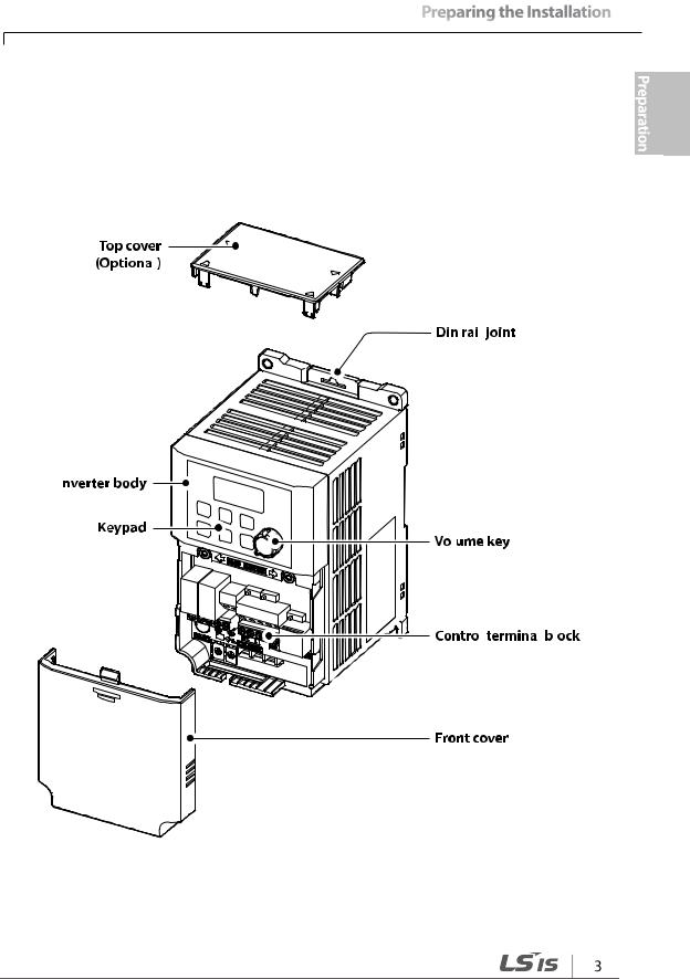
1.2 Part Names
The illustration below displays part names. Details may vary between product groups.
0.1~0.2 kW (Single Phase)
표
도
능
능
능
능
능
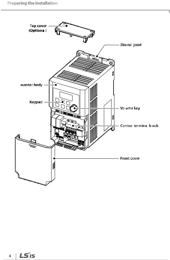
0.4~0.75 kW (Single Phase)
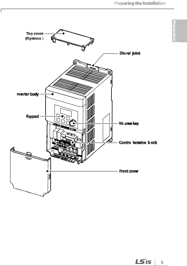
1.5~2.2 kW (Single Phase)
표
도
능
능
능
능
능
1.3 Installation Considerations
Inverters are composed of various precision, electronic devices, and therefore the installation environment can significantly impact the lifespan and reliability of the product. The table below details the ideal operation and installation conditions for the inverter.
|
Items |
|
Description |
|
|
Ambient Temperature |
|
14–122 F (-10–50 ) |
|
|
1) |
|
|
|
|
|
|
|
|
|
Ambient Humidity |
|
95% relative humidity (no condensation) |
|
|
Storage Temperature |
|
- 4–149 F (-20–65 ) |
|
|
Environmental Factors |
|
An environment free from corrosive or flammable gases, oil residue or |
|
|
|
dust |
|
|
|
|
|
|
|
|
Altitude/Vibration |
|
Lower than 3,280 ft (1,000 m) above sea level/less than 1G (9.8 |
|
|
|
m/sec2) |
|
|
|
|
|
|
|
|
Air Pressure |
|
70~106 kPa |
|
1) The ambient temperature is the temperature measured at a point 2” (5 cm) from the surface of the inverter.
Do not allow the ambient temperature to exceed the allowable range while operating the inverter.
1.4 Selecting and Preparing a Site for Installation
When selecting an installation location consider the following points:
•The inverter must be installed on a wall that can support the inverter’s weight.
•The location must be free from vibration. Vibration can adversely affect the operation of the inverter.
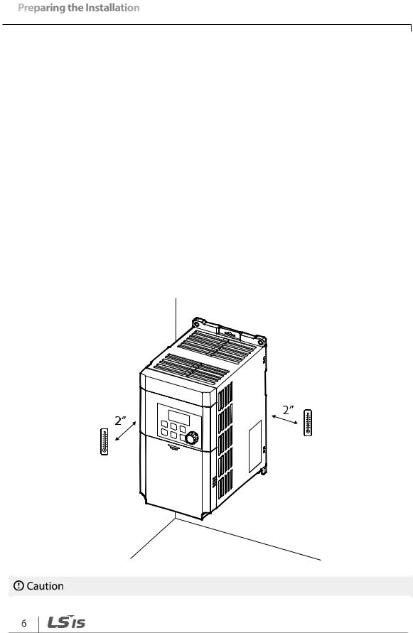
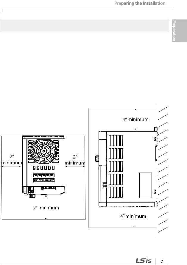
•The inverter can become very hot during operation. Install the inverter on a surface that is fire-resistant or flame-retardant and with sufficient clearance around the inverter to allow air to circulate. The illustrations below detail the required installation clearances.
표
도
능
능
능
능
능

•Ensure sufficient air circulation is provided around the inverter when it is installed. If the inverter is to be installed inside a panel, enclosure, or cabinet rack, carefully consider the position of the inverter’s cooling fan and the ventilation louver. The cooling fan must be positioned to efficiently transfer the heat generated by the operation of the inverter.
•If you are installing multiple inverters in one location, arrange them side by side and remove their top covers (optional). The top covers MUST be removed for side-by-side installations. Use a flat head screwdriver to remove the top covers.
•Keep the distance between inverters at least 0.1’’.
표
도
능
능
능
능
능
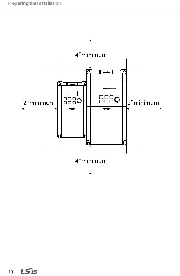
•If you are installing multiple inverters, of different ratings, provide sufficient clearance to meet the clearance specifications of the larger inverter.

1.5 Cable Selection
When you install power and signal cables in the terminal blocks, only use cables that meet the required specification for the safe and reliable operation of the product. Refer to the following information to assist you with cable selection.
•Wherever possible use cables with the largest cross-sectional area for mains power wiring, to ensure that voltage drop does not exceed 2%.
•Use copper cables rated for 600V, 75 for power terminal wiring.
•Use copper cables rated for 300V, 75 for control terminal wiring.
Ground Cable and Power Cable Specifications
|
|
|
|
Ground |
|
|
|
Power I/O |
|
|
|
|
||||
|
Load (kW) |
|
mm2 |
|
AWG |
|
mm2 |
|
|
AWG |
|
|||||
|
|
|
|
|
|
|
||||||||||
|
|
|
|
|
R/S/T |
|
|
U/V/W |
|
R/S/T |
|
|
U/V/W |
|
||
|
|
|
|
|
|
|
|
|
|
|
|
|
||||
|
|
|
|
|
|
|
|
|||||||||
|
|
0.1 |
|
|
|
|
|
|
|
|
|
|
|
|
|
|
|
|
0.2 |
3.5 |
12 |
2 |
|
|
2 |
14 |
|
14 |
|
||||
|
Single Phase |
0.4 |
|
|
|
|
||||||||||
|
|
|||||||||||||||
|
|
|
|
|
|
|
|
|
|
|
|
|
|
|
||
|
200V |
0.75 |
|
|
|
|
|
|
|
|
|
|
|
|
|
|
|
|
1.5 |
|
|
|
|
|
|
|
|
|
|
|
|
|
|
|
|
3.5 |
12 |
3.5 |
|
|
3.5 |
12 |
|
12 |
|
|||||
|
|
|
|
|
|
|||||||||||
|
|
2.2 |
|
|
|
|
||||||||||
|
|
|
|
|
|
|
|
|
|
|
|
|
|
|
|
|
Signal (Control) Cable Specifications
|
|
|
|
|
Signal Cable |
|
|
||
|
|
|
Without Crimp Terminal |
|
With Crimp Terminal Connectors |
|
|||
|
|
|
|
|
|||||
|
Terminal |
|
|
Connectors |
|
|
|||
|
|
|
|
(Bootlace Ferrule) |
|
||||
|
|
|
|
(Bare wire) |
|
|
|||
|
|
|
|
|
|
|
|
||
|
|
|
mm2 |
|
AWG |
|
mm2 |
AWG |
|
|
P1~P5/CM/VR/V1/I2 |
0.75 |
|
18 |
0.5 |
20 |
|
||
|
/AO/Q1/EG/241) |
|
|
||||||
|
|
|
|
|
|
|
|
|
|
|
A1/B1/C1/A2/C21) |
1.0 |
|
17 |
1.5 |
15 |
|
||
1) There are no P4, P5, I2, A2, and C2 terminals on the standard I/O, and there are no Q1 and EG terminals on the Advanced I/O. For more details, refer to 2.2 Cable Wiring Step 4 Control Terminal Wiring on page 24.
표
도
능
능
능
능
능

2 Installing the Inverter
This chapter describes the physical and electrical installation methods, including mounting and wiring of the product. Refer to the flowchart and basic configuration diagram provided below to understand the procedures and installation methods to be followed to install the product correctly.
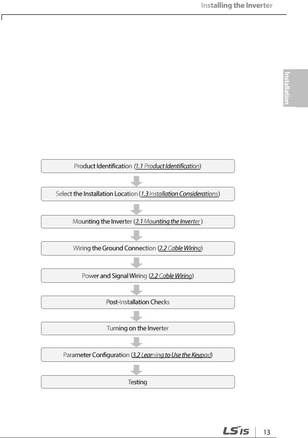
Installation Flowchart
The flowchart lists the sequence to be followed during installation. The steps cover equipment installation and testing of the product. More information on each step is referenced in the steps.
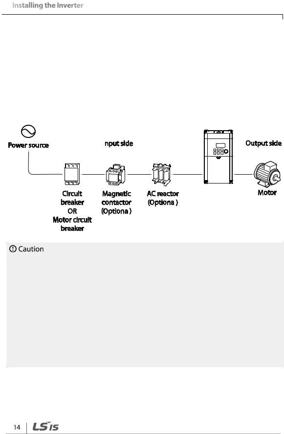
Basic Configuration Diagram
The reference diagram below shows a typical system configuration showing the inverter and peripheral devices.
Prior to installing the inverter, ensure that the product is suitable for the application (power rating, capacity, etc). Ensure that all of the required peripherals and optional devices (resistor brakes, contactors, noise filters, etc.) are available. For more details on peripheral devices, refer to 0 Unit: mm (inches)
Peripheral Devices on page 247.
•Figures in this manual are shown with covers or circuit breakers removed to show a more detailed view of the installation arrangements. Install covers and circuit breakers before operating the inverter. Operate the product according to the instructions in this manual.
•Do not start or stop the inverter using a magnetic contactor, installed on the input power supply.
•If the inverter is damaged and loses control, the machine may cause a dangerous situation. Install an additional safety device such as an emergency brake to prevent these situations.
•High levels of current draw during power-on can affect the system. Ensure that correctly rated circuit breakers are installed to operate safely during power-on situations.
•Reactors can be installed to improve the power factor. Note that reactors may be installed within 30 ft (9.14 m) from the power source if the input power is 10 times over the inverter’s power. Refer to 12.5 Fuse and Reactor Specifications on page 247 and carefully select a reactor that meets the equipment.
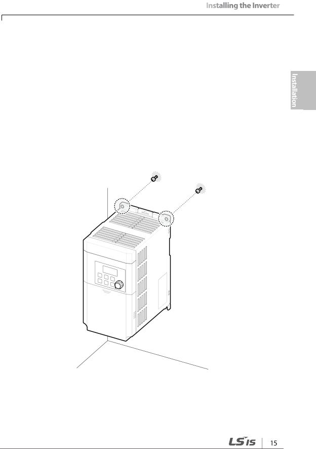
2.1 Mounting the Inverter
Mount the inverter on a wall or inside a panel following the procedures provided below. Before installation, ensure that there is sufficient space to meet the clearance specifications, and that there are no obstacles impeding the cooling fan’s air flow.
Select a wall or panel suitable to support the installation. Refer to 12.3 External Dimensions (IP 20 Type) on page 245 and check the inverter’s mounting bracket dimensions.
1Use a level to draw a horizontal line on the mounting surface, and then carefully mark the fixing points
2Drill the two upper mounting bolt holes, and then install the mounting bolts. Do not fully tighten the bolts at this time. Fully tighten the mounting bolts after the inverter has been mounted.
비
표
도
능
능
능
능
능
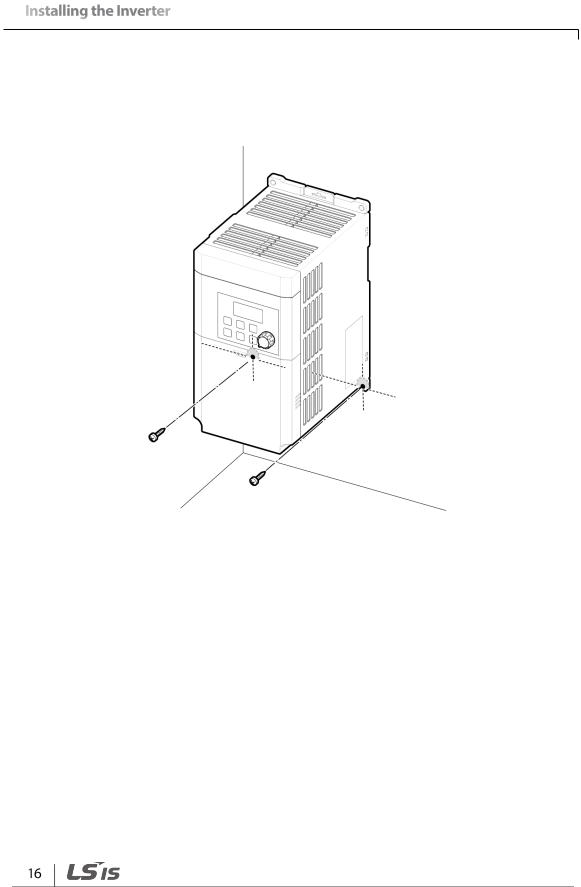
3Mount the inverter on the wall or inside a panel using the two upper bolts, and then fully tighten the mounting bolts. Ensure that the inverter is placed flat on the mounting surface, and that the installation surface can securely support the weight of the inverter.
Note
The quantity and dimensions of the mounting brackets vary based on frame size. Refer to 12.3 External Dimensions (IP 20 Type) on page 245 for detailed information about your model.
•Do not transport the inverter by lifting with the inverter’s covers or plastic surfaces. The inverter may tip over if covers break, causing injuries or damage to the product. Always support the inverter using the metal frames when moving it.
•Use an appropriate transport method that is suitable for the weight.
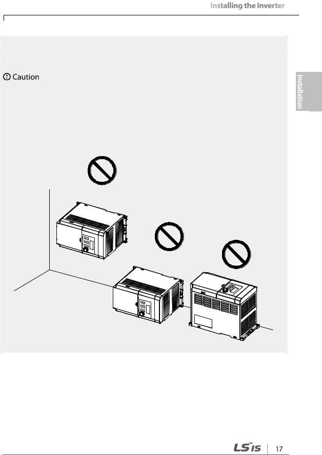
•Do not install the inverter on the floor or mount it sideways against a wall. The inverter MUST be installed vertically, on a wall or inside a panel, with its rear flat on the mounting surface.
비
표
도
능
능
능
능
능

2.2 Cable Wiring
Remove the control terminal cover, and then install the ground connection as specified. Complete the cable connections by connecting an appropriately rated cable to the terminals on the power and control terminal blocks.
•Install the inverter before carrying out wiring connections.
•Ensure that no small metal debris, such as wire cut-offs, remain inside the inverter. Metal debris in the inverter may cause inverter failure.
•Tighten terminal screws to their specified torque. Loose terminal block screws may allow the cables to disconnect and cause short circuit or inverter failure. Refer to 12.6 Terminal Screw Specification on page 248 for torque specifications.
•Do not place heavy objects on top of electric cables. Heavy objects may damage the cable and result in electric shock.
•The inverter’s power is supplied by the supply grounding system. The TT, TN, IT, and cornergrounded systems are not suitable for this inverter.
•The inverter may generate direct current to the inverter’s protective ground cable. Only type
B Residual Current Devices (RCD) or Residual Current Monitors (RCM) can be installed.
•Use cables with the largest cross-sectional area, appropriate for power terminal wiring, to ensure that voltage drop does not exceed 2%.
•Use copper cables rated at 600V, 75 for power terminal wiring.
•Use copper cables rated at 300V, 75 for control terminal wiring.
•Connect the control terminals separately from the power terminal wiring or high potential circuit (200 V relay sequence circuit).
•Ensure that there are no control terminal shorts or improper wiring. Control terminal shorts or improper wiring may damage the inverter or cause malfunction.
•Use a shielded cable while making wiring connections at the control terminal. Unshielded cables may cause the inverter to malfunction due to interference. Use an STP cable if ground connections must be installed.
•If you need to re-wire the terminals due to wiring-related faults, ensure that the inverter keypad display is turned off and the charge lamp under the front cover is off before working on wiring connections. The inverter may hold a high voltage electric charge long after the power supply has been turned off.
 Loading...