

INSTRUCTION MANUAL
1800
RADAR
Color Radar / Plotter
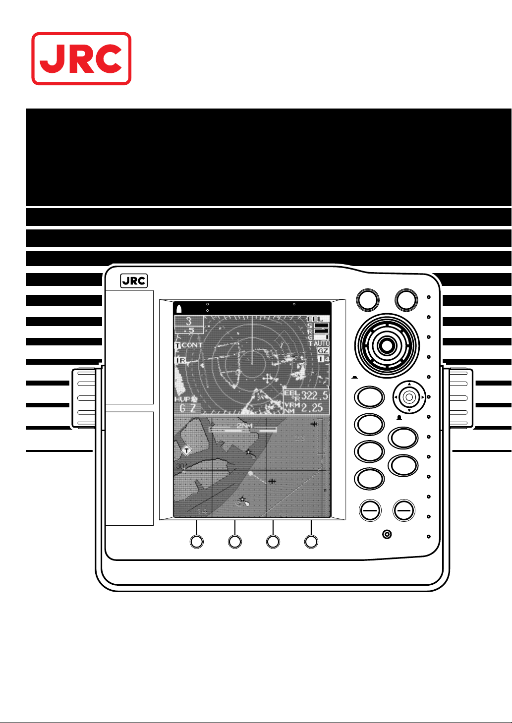
1800
RADAR
COLOR LCD RADAR-PLOTTER
MOB
MENU
RANGE
NAV
MODE
EBL/VRM
CENTER
BRT/CLR
STBY
OFF
TX
OFF
PUSH
OPEN
PUSH
OPEN
C-MAP CARD
PC I/F PORT
PUSH
EVENT/ENT
PUSH
SELECT
N 42 31.000'COG122.3 T DGPS
W 81 49.000'SOG 25.5KTS

Color Radar/Plotter
Before You Begin
Thank you for purchasing our RADAR 1800 Color LCD
Radar/Plotter.
This unit is a sophisticated and easy to use integrated color radar and
color plotter. When the unit is connected to a GPS or Loran
navigation system, the color plotter function allows you to continuously display latitude, longitude, scale division and track line of the
vessel color.
•This unit is a compact LCD radar with a 2 kw transmitter & 6.5
inch color LCD. Before attempting to operate it, read this
instruction manual thoroughly to correctly and safely operate this
unit in accordance with the warning instructions and operation
procedures in this manual.
•Storing this instruction manual carefully for future reference is
highly recommended. In the event that you have an operational
problem or malfunction, this manual will provide useful
instructions.
•This unit is an aid to navigation. Its accuracy can be affected by
many factors including equipment failure or defects, environmental
conditions, and improper handling or use. It is the user’s
responsibility to exercise common prudence and navigational
judgment. This unit should not be relied on as a substitute for such
prudence and judgment.
•The LCD uses 224,000 or more TFTs (Thin Film Transistor).
If some pixels on the screen are not clear, the color is different, or the
screen is brighter than usual, it is not because of defect, instead it is
because of inherent characteristics of the TFT display technology.
Trademarks of other companies C-MAP® Micro C-Card used in this
manual is a trademark of C-MAP Co., Ltd.
1
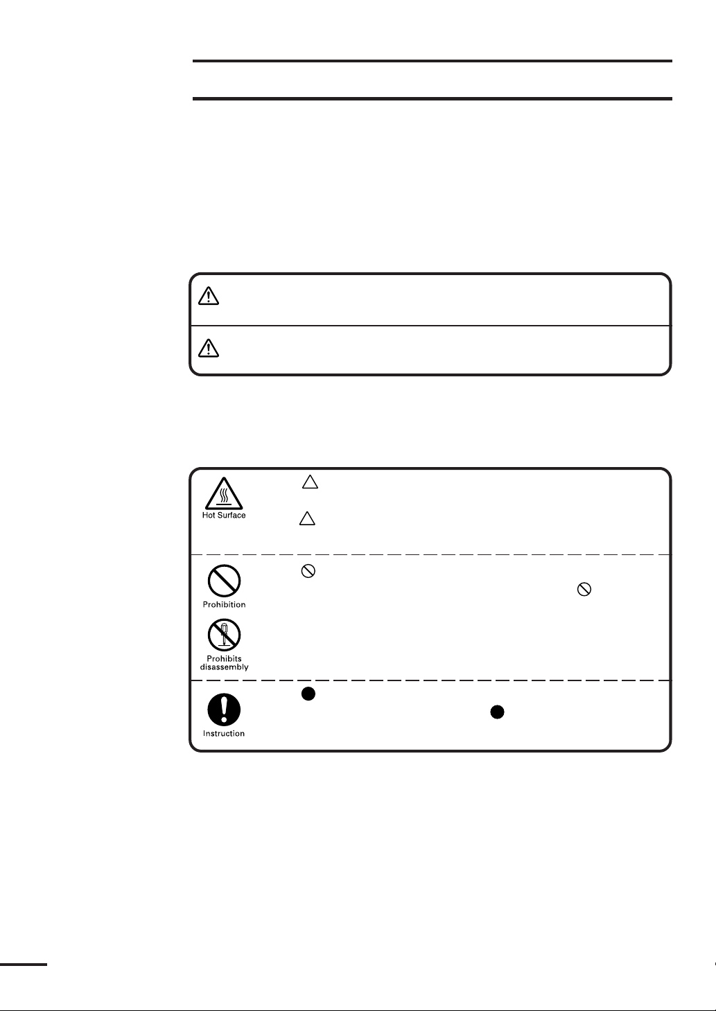
Symbols Used In This Manual
Related Symbol Marks
In this manual, and on the equipment, we use several warning signs to call
your attention to important items that, if not handled correctly, could present
danger to yourself or property. These warning note classifications are as described
below.
Please be fully aware of the importance of these items before using this
manual.
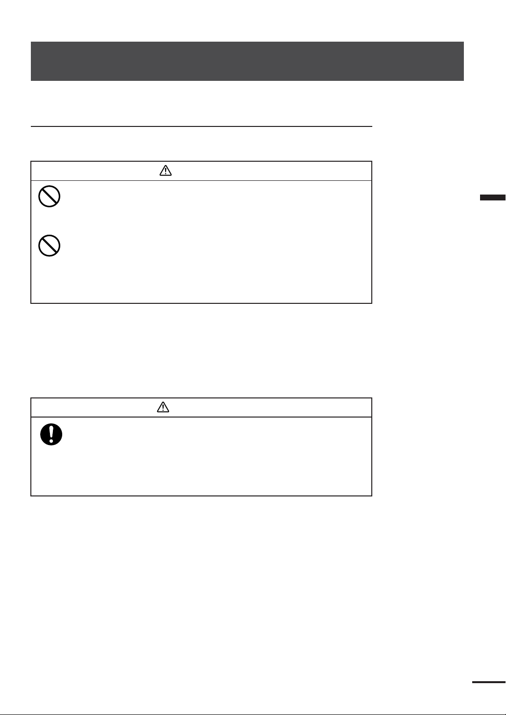
WARNING
CAUTION
Indicates warning items that, if ignored, may result in
serious personal injury or even death.
Indicates cautionary items that, if ignored, may result
in personal injury or physical damage.
Examples of Related Symbol Marks Used in this Manual
and on the Unit
Each mark is intended to alert the user to the presence of
precautions including danger and warning items. The picture in
each mark alerts you to operations that should be carefully
performed.
Each
prohibited activity. The picture/word in/beside each mark alerts
you to operations that are prohibited.
mark is intended to alert the user to the presence of
Each
sary instructions. The picture in each mark alerts you to operations that must be performed.
mark is intended to alert the user to the presence of neces-
WARNING LABEL
You can see the warning label on the top of the unit.
Do not attempt to remove the warning label from the unit or impair or
modify it.
2
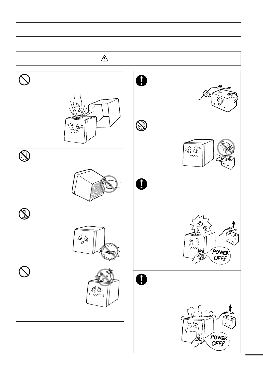
Usage Hints
WARNING
Do not remove the cover of the
unit. Doing so may cause an
electric shock
by high voltage
from within
the product’s
enclosure.
Do not touch the radiator fin of the
unit. Doing so
may cause a burn
by high
temperature.
Do not try to disassemble or
modify the unit.
Doing so may
cause a fire,
electric shock
or malfunction.
Operate the unit only
on 12 VDC.
Not doing so may
cause fire or
electrical shock.
Do not (dis)connect the power
cable(from) to the main unit with
wet hands, as
doing so
may cause
electrical
shock.
In the event that you spill or drop
any liquids or metals, etc. inside the
unit, turn off the main unit, unplug
the power supply terminal, and
contact our company, branch, or
local office.
Continuing
operation as
is may cause
a fire, electric
shock or
malfunction.
Do not place objects
containing liquid or
metal fragments on
top of the unit,
which might be
spilled or dropped
into the unit.
Doing so may cause a
fire, electric shock or malfunction.
In the event that smoking or burning
odors are detected, immediately
terminate operation of the unit and
contact your dealer. Continuing
operation as is may cause
a fire or
electrical
shock.
Never
attempt
to service
the interior
of the unit.
3
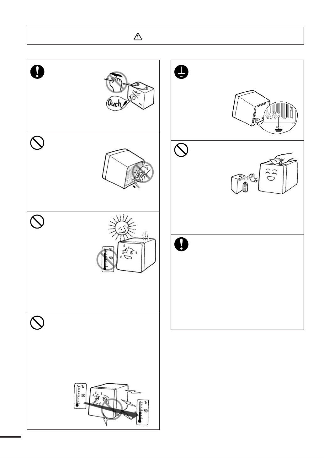
CAUTION
When disconnecting
the power cable,
be sure to grasp
it by the plug.
Never pull on the
connecting cord
itself, as doing so
increases the risk
of malfunction.
Do not drop the unit
into water. When
disconnecting the
connector on the
back side,
be sure it does
not get wet, as
doing so increases
risk of electrical shock or
malfunction.
Do not use or
install the unit
in a place where
the LCD is subject
to direct
sunlight, or in
a location near
heat sources
where the temperature
is 50°C (Display Unit), 55°C (Scanner
Unit) or more.
Doing so may cause a malfunction
or defect.
Do not turn on the unit immediately
after moving it from a cold place to a
warm one. Let the unit stand for
around 30 minutes before turn on,
until the inside temperature of the
unit reaches the same level as that of
the room it was moved to.
Not doing so increases risk of
malfunction.
Be sure to connect a cable to the
grounding terminal when installing.
Not doing so may cause an electric
shock or
excessive
noise from/
to other
equipment.
Do not use any type
of organic solvent
such as thinner
or benzine
when
cleaning the
surface of
the cabinet.
Doing so may damage the coating or
the finish of the unit’s surface.
Remove any dust and clean the unit’s
surface with a soft dry cloth.
This device is only an aid to
navigation.
• The information displayed by the
unit cannot be directly used for
navigation purposes.
It must be used together with the
appropriate marine charts.
• The unit does not automatically
assess position information.
It is the user's responsibility to judge
position and navigational
information.
4

EMC Installation & Service Guidelines
IMPORTANT NOTE
All JRC equipment and accessories are designed to the highest industry
standards for use in a marine environment. Their design and manufacture
conforms to the appropriate Electro Magnetic Compatibility (EMC) standards,
but good installation is required to ensure that performance is not compromised.
Although every effort has been taken to ensure that the equipment will perform
under all conditions, it is important to understand what factors could affect
operation of the product. Complete installation instructions are provided in
SECTION 2 of this manual. Some preliminary suggestions are made below.
Installation
To avoid the risk of operating problems, all JRC equipment and cables
connected to it should be:
•At least 1m (3 feet) from any equipment transmitting or cables carrying radio
signals e.g. VHF radios, cables and antennas. In the case of SSB radios the
distance should be increased to 2m (7 ft).
•More than 2 m (7 ft) from the path of a radar beam. A radar beam can nor-
mally assume to spread 20 degrees above and below the radiating element.
•The equipment should be supplied from a different battery than the one used
for engine start. Voltage drops below 10.2V in the power supply to our
products can cause the equipment to reset. This will not damage the
equipment, but will cause some loss of information and this can also change the
operating mode.
•Genuine JRC Cables should be used at all times. Cutting and rejoining these
cables can compromise EMC performance and should therefore be avoided
unless doing so is suggested in the installation manual.
Check Before Going to Sea
• Always check the installation before going to sea to make sure that it is not
affected by radio transmissions, engine starting, low battery voltage, or other
problems.
•In some, installations, it may not be possible to prevent the equipment from
being affected by external influences. In general this will not damage the
equipment but it can lead to it resetting, or momentarily may result in faulty
operation. This can then be avoided by turning off the RADAR 1800 prior to
starting the boat engines for instance.
5
Servicing and Safety
•JRC equipment should be serviced only by authorized JRC service engineers.
They will ensure that service procedures and replacement parts used will not
affect performance. There are no user serviceable parts in any JRC product.
•Some products generate high voltages, and so never handle the cables/connectors when power is being supplied to the equipment.
• Always report any EMC related problem to your nearest JRC dealer. We will
use any such information to improve our quality standards.
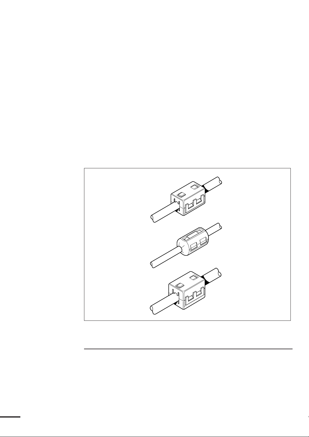
Suppression Ferrites
The following illustration shows the range of suppression ferrites fitted to
JRC equipment.
Notes for Suppression Ferrite Installation
Connections to other equipment
If your JRC equipment is going to be connected to other equipment using a
cable not supplied by JRC, a suppression ferrite MUST always be fitted to the
cable close to the JRC unit.
6
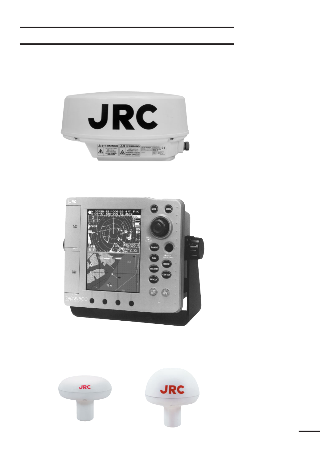
Outside View
Scanner Unit
Display Unit
GPS/DGPS Sensor (Option)
GPS-112/GPS-112W DGPS212/GPS-212W
7

Contents
Before you begin ............................................................................... 1
Symbols used in This Manual .......................................................... 2
Usage Hints ....................................................................................... 3
EMC Installation & Service Guidelines ........................................... 5
Outside View ..................................................................................... 7
Definition on Terms ......................................................................... 16
SECTION 1 Introduction ....................................... 19
Function ........................................................................................19
Features .........................................................................................20
Components ..................................................................................21
Standard Equipment..................................................................... 21
GPS Sensor (Option) ................................................................... 21
Construction .................................................................................22
System Configuration....................................................................24
SECTION 2 Installation.......................................... 25
Installing the Display Unit ............................................................25
Choosing a Location for Installation............................................. 25
Standard Mounting ...................................................................... 25
Console Mounting/ Surface Mounting ......................................... 27
Installing the Scanner unit ............................................................28
Connecting the Scanner Unit Cable .............................................28
Installing the GPS/DGPS Sensor ..................................................29
Selecting the Position for Installation ............................................ 29
Installation Procedure ................................................................... 31
Connecting DC Power ..................................................................33
Grounding the Display Unit .........................................................34
Connecting GPS/DGPS Sensor or Making NMEA0183 Data
Connections (Option) ...............................................................35
Connecting Electronic Compass/GPS Compass (Option).............37
Initial Operation and Set-up .........................................................37
Inspection after Installation ..........................................................37
Operating the INSTALLATION menu ........................................ 38
RADAR SET UP ......................................................................... 38
8

TUNE PRESET ..................................................................... 38
Relative BEARING alignment ................................................39
DISPLAY TIMING ................................................................ 39
STC PRESET ......................................................................... 39
Connecting Personal Computer ....................................................40
Inserting a Chart Card ..................................................................41
Removing a Chart Card.................................................................41
SECTION 3 Operation ........................................... 42
Screen Layout ................................................................................42
Control Panel ................................................................................45
Rear Panel .....................................................................................47
Basic Operations ...........................................................................48
The Power Control (Turning the Radar ON and OFF) ................49
LCD Backlight and Contrast Control........................................... 49
Display Modes..............................................................................49
Vessel’s Information/Waypoint’s Information ................................ 53
Graph Display .............................................................................. 54
Finding Function.......................................................................... 54
Using the Jog Dial ........................................................................55
Using the Joy Stick .......................................................................55
Changing CURSOR Operation in RADAR/CHART Mode ........55
General MEMU Operation .......................................................... 55
Buzzer ON/OFF .......................................................................... 56
Setting LANGUAGE ................................................................... 56
Radar Operation ........................................................................... 57
Selecting a RANGE ...................................................................... 57
Adjusting Receiver Sensitivity ....................................................... 58
Adjusting TUNING..................................................................... 58
Reducing SEA CLUTTER ...........................................................58
Adjusting RAIN CLUTTER ........................................................59
Setting OFFSET .......................................................................... 59
Range Measurement ..................................................................... 59
Bearing Measurement ................................................................... 60
Changing CURSOR Operation Mode
in RADAR/CHART Screen ..................................................... 60
RADAR Operating Menu ............................................................ 61
RINGS ......................................................................................... 61
DISPLAY MODE (BEARING) ................................................... 61
9

INTERFERENCE REJECTION ................................................ 62
Setting AUTO/MANUAL SEA Clutter Rejection ........................63
Setting AUTO/MANUAL TUNING........................................... 63
Target EXPANDER ..................................................................... 63
PROCESS .................................................................................... 64
TRAILS........................................................................................ 64
CLEAR TRAILS ..........................................................................65
WAYPOINT ................................................................................ 65
Setting Radar COLOR ................................................................. 65
PLANNED-TX MODE .............................................................. 66
Setting GUARD ZONE ............................................................... 67
Display of RADAR Transponder .................................................. 69
Plotter Operation ..........................................................................71
Using the Joy Stick in CHART mode ...........................................71
Enter the Event ....................................................................... 71
Enter the WAYPOINT or the MARK..................................... 71
Enter the WAYPOINT ........................................................... 71
Soft Keys at the WAYPOINT Mode ....................................... 72
Enter the MARK Mode .......................................................... 72
Man Overboard............................................................................ 73
Range Setting ............................................................................... 73
In the CHART display............................................................ 73
In the CDI/COMPASS display............................................... 73
In the RADAR display ............................................................73
In the RADAR/CHART display .............................................74
Navigation Setting........................................................................ 74
SELECT ROUTE (Selecting Navigation) ............................... 74
WAYPOINT DIRECT (Selecting a waypoint) ........................................................ 74
PLANNED ROUTE (Navigating according to a planned route) ............................. 75
TEMPORARY ROUTE (Navigating according to a temporary route) .................... 75
NEAREST PORT (Searching for and navigating to a nearest port) ......................... 77
PREVIOUS MOB (Setting a waypoint to the MOB).............................................. 77
SEQUENCE (Selecting the order of waypoint navigation) ..... 77
WPT STEP (Selecting the method to switch the waypoint) ....78
NEXT WPT (Skipping to the next waypoint)......................... 78
PREV. WPT (Skipping to the previous waypoint) ................... 78
STOP WATCH ...................................................................... 78
TIDAL INFO
(Displaying tide height graph of a specified point).............. 79
10

OBJECT INFO
(Displaying detailed information of a specified point) ........ 79
EDIT ........................................................................................... 80
Editing a waypoint .................................................................. 80
EDIT IN CHART .................................................................................................. 80
Storing a waypoint ............................................................................................ 80
Modifying a waypoint ....................................................................................... 81
Erasing a waypoint ............................................................................................ 81
Moving waypoint .............................................................................................. 81
Go to a waypoint .............................................................................................. 81
EDIT BY LIST ....................................................................................................... 82
Storing a waypoint ............................................................................................ 82
Modifying a waypoint ....................................................................................... 82
Copying a waypoint .......................................................................................... 83
Erasing a waypoint ............................................................................................ 83
Jumping to a waypoint list page ........................................................................ 83
Planning a route...................................................................... 83
Storing a new route ................................................................................................. 83
Editing a route ........................................................................................................ 84
Adding a new waypoint ........................................................................................... 84
Editing a waypoint .................................................................................................. 84
CHANGE ............................................................................................................... 84
INSERT .................................................................................................................. 84
ERASE .................................................................................................................... 84
Converting a track to a planned route .....................................85
Selecting a new route ............................................................................................... 85
DIVIDE .................................................................................................................. 86
CONSTRUCT ....................................................................................................... 86
Construction........................................................................... 86
Constructing a line .................................................................................................. 86
Constructing a rectangle .......................................................................................... 87
Menu Operations ..........................................................................88
General......................................................................................... 88
Top Menu .................................................................................... 88
RADAR SETTING ................................................................88
RINGS .................................................................................................................... 88
BEARING .............................................................................................................. 89
INTERFERENCE REJECTION ........................................................................... 89
SEA ......................................................................................................................... 89
TUNE ..................................................................................................................... 89
EXPANDER ........................................................................................................... 89
PROCESS ............................................................................................................... 89
TRAILS .................................................................................................................. 89
CLEAR TRAILS ..................................................................................................... 89
WAYPOINT ........................................................................................................... 89
11

COLOR .................................................................................................................. 89
TX-PLAN ............................................................................................................... 90
PLOT SETTING ...................................................................90
TRACK ERASE (Erasing a track) ........................................................................... 90
MARK ERASE (Erasing a mark) ............................................................................. 90
MARK SIZE (Selecting a size) ................................................................................. 90
TRACK SETUP ..................................................................................................... 90
TRACK PLOT (Selecting memory intervals) .................................................... 90
MEMORY SIZE (Selecting a number of points)............................................... 90
TRACK COLOR (Selecting a color)................................................................. 90
VESSEL SHAPE (Selecting a mark for your vessel) ........................................... 90
VESSEL SIZE (Selecting a size of your vessel’s mark) ........................................ 90
L/L-TD CONVERT............................................................................................... 91
POSTION DISPLAY (Selecting a format of position display) .......................... 91
LORAN-C CHAIN (Selecting a format of LORAN-C CHAIN)...................... 91
TD CORRECTION (Selecting a format of time difference) ............................ 91
CHART DISPLAY .................................................................................................. 91
CHART DISP MODE (Selecting a chart display mode)................................... 91
SCALE BAR (Turning the scale bar ON/OFF) ................................................. 91
VECTOR RAY (Selecting a type of direction display) ....................................... 91
BRG LINE (Turning the direction line ON/OFF) ............................................ 91
WAYPOINT (Selecting a waypoint display) ...................................................... 91
CURSOR INFO (Turning the cursor information ON/OFF) .......................... 91
L/L GRID (Turning the grid ON/OFF) ........................................................... 91
CHART COLORS ................................................................................................. 92
LAND (Selecting a color for the land)............................................................... 92
SEA (Selecting a color for the sea) ..................................................................... 92
L/L GRID (Selecting a color for the grid) ......................................................... 92
CUSTOM CHART ................................................................................................ 92
CHART BOUNDARY ..................................................................................... 92
LIGHT SECTORS........................................................................................... 92
BUOY & BEACON ......................................................................................... 92
NAMES ............................................................................................................ 92
LAND MARKS ................................................................................................ 92
RIVER & LAKE ............................................................................................... 92
CULTURAL ..................................................................................................... 92
BOTTOM TYPE.............................................................................................. 92
UNDER WATER ............................................................................................. 92
SOUNDING DEPTH ..................................................................................... 92
DEPTH SHADING ......................................................................................... 92
DEPTH CONTOUR ...................................................................................... 93
DETAILED ...................................................................................................... 93
GRAPH SETTING ................................................................ 93
GRAPH DISPLAY (Selecting what to display) ........................................................ 93
DEPTH SCALE (Setting a display range of the water depth graph) ........................ 93
TEMP. SCALE (Setting a display range of the temperature graph) .......................... 93
12

SPEED SCALE (Setting a display range of the speed graph) ................................... 93
GPS SETTING ...................................................................... 94
VESSEL POSITION (Setting the vessel position) ................................................... 94
TIME DIFFERENCE (Setting the time difference) ................................................ 94
ANTENNA HEIGHT (Setting the antenna height) ............................................... 94
GEODETIC DATUM (Setting a geodetic system) ................................................. 94
FIX MODE (Setting the fixing mode) .................................................................... 94
HDOP LEVEL (Setting the HDOP level) .............................................................. 95
AVERAGE (Setting an interval to average the data)................................................. 95
EXCLUDE SAT (Setting the satellite number not used) ......................................... 95
DGPS SETTING ...................................................................95
MODE (Setting the reception mode of the beacon) ................................................ 95
FREQUENCY (Setting the beacon frequency) ........................................................ 95
BAUDRATE (Setting the beacon baud rate) ........................................................... 95
WAAS SETTING................................................................... 96
MODE ................................................................................................................... 96
RANGING ............................................................................................................. 96
NG WAAS .............................................................................................................. 96
WAAS NO. ............................................................................................................. 96
INSTALLATION ................................................................... 97
SIMULATION (Turning the simulator ON/OFF) ................................................. 97
INITIAL POSITION (Setting the standard position of the chart display) .............. 97
CLOCK ADJUST (Adjusting the date and time) .................................................... 97
DATE & TIME (Selecting a system of time) ........................................................... 97
RADAR ADJUST (Adjusting the radar) ................................................................. 97
DATA IN/OUT ...................................................................................................... 98
TEMP. IN (Selecting temperature input) .......................................................... 98
DEPTH IN (Selecting depth data input) .......................................................... 99
COURSE IN (Selecting course data input) ....................................................... 99
POSITION IN (Selecting position input) ........................................................ 99
NMEA OUT (Putting out data) ..................................................................... 100
UNITS .................................................................................................................. 100
DEPTH (Selecting depth units) ...................................................................... 100
YOUR DEPTH (Setting custom depth units)................................................. 100
TEMPERATURE (Changing temperature units) ............................................ 100
SPEED & DIST UNIT (Changing speed and distance units) ......................... 100
CALIBRATION ................................................................................................... 100
LAT/LON (Calibrating the longitude/latitude) ............................................... 100
MAGNETIC CORR. (Correcting the magnetic compass) .............................. 101
RESET LOG (Resetting the trip log) .............................................................. 101
OPERATION ....................................................................................................... 101
J-STICK PUSH .............................................................................................. 101
CENTERING ................................................................................................ 101
GUIDE ........................................................................................................... 101
13

CUSTOM SETUP ...............................................................102
PRESET ................................................................................................................ 102
CUSTOM INITIALIZE ....................................................................................... 102
MEMORY COPY ................................................................ 102
USE THE CARD ................................................................................................. 103
USE THE PC ....................................................................................................... 104
ALARM ................................................................................ 105
NAV ALARM (Navigation alarms)........................................................................ 105
RADAR ALARM .................................................................................................. 107
BZ ALARM .......................................................................................................... 107
TEMP. ALARM (Temperature alarms) .................................................................. 108
CLOCK ALARM .................................................................................................. 108
BUZZER (Alarm buzzer) ...................................................................................... 108
Self Test Operation ......................................................................109
Master Reset and Language Select Operation..............................110
SECTION 4 Maintenance ..................................... 115
General ........................................................................................115
Scanner Unit................................................................................115
Radome Scanner Unit ................................................................ 116
Display Unit ................................................................................116
Cleaning the Display Unit Screen ............................................... 116
SECTION 5 Principle ........................................... 117
Radar Basics ................................................................................117
Strength of Reflection from the Targets ......................................117
Sea Clutters ................................................................................ 117
False Echoes................................................................................ 118
GPS/DGPS Basics .......................................................................120
GPS............................................................................................ 120
Differential GPS (DGPS) ........................................................... 121
Wide Area Augmentation System (WAAS) .................................122
SECTION 6 Interswitch (option).......................... 123
Outline ........................................................................................123
Components............................................................................... 123
Construction .............................................................................. 124
Installation ..................................................................................125
Setting Jumpers ..........................................................................125
Unit Connecting Cable .............................................................. 126
14

Operation ....................................................................................128
The following is for the jumpers in the junction box. (setting 1)...........
The following is for the jumpers in the junction box. (setting 2)...........
128
128
SECTION 7 After-Sales Service ............................. 130
When Asking for Service .............................................................130
Checks and Inspection ................................................................130
SECTION 8 Disposal ............................................ 131
Disposal of LCD Module ............................................................131
Handling Used Lithium Batteries................................................ 131
SECTION 9 Specification ..................................... 132
General ........................................................................................132
Scanner........................................................................................133
Display Unit ................................................................................134
Radar ........................................................................................... 135
Plotter .........................................................................................137
Input/Output Signal ...................................................................138
APPENDICES.................................................139
Wiring Diagram ..........................................................................139
Geodetic System Table .................................................................140
NMEA0183 Standard Input/Output Sentences ...........................141
Input Sentences .......................................................................... 141
Output Sentences ....................................................................... 142
Waypoint List .............................................................................. 143
15

Definition on Terms
2D(two- dimensional)..... Position fixing using satellites and height information.
3D(three-dimensional).... Position fixing using satellite information only from
four or more satellites.
Anchor alarm .................. An alarm indicating that the vessel has deviated more
than the set distance from a waypoint.
Arrival alarm ................... An alarm indicating that the vessel has come within
the set distance of a waypoint.
Automatic sequencing mode
....................................... Function that automatically steps from one waypoint
to the next when the arrival perpendicular point has
been detected.
Bow ................................ The front of a vessel (nautical term)
CDI ................................ Course Deviation Indicator. Information that
indicates the extent you have strayed from the route
intended and the direction to steer.
COG .............................. Course over Ground
CUP(Course-UP) ........... An azimuth stabilized display in which a line connect-
ing the centre of own ship with the top of the display
is own ship’s intended course.
Default value .................. Factory set value
DGPS ............................. The process of correcting the inaccuracies of GPS
position data from GPS satellites by receiving a beacon
Differential Signal from a base station whose exact
position is known. And which transmits correction
data for the GPS satellites it receives.
EBL(Electric Bearing Line)
....................................... Electronic Bearing Line – A moveable vector line
radiating out from the ship indicating the bearing
thereof.
GPS(Global Positioning System)
....................................... Internationally-used positioning system.
Ground stabilization ....... A mode of display whereby own ship and all targets
are referenced to the ground using ground track or set
and drift inputs.
GPS satellite ................... GPS stands for “Global Positioning System.” Several
satellites launched by the US Department of Defense
to establish a military navigational aid system.
Guard zone ..................... A zone in which an alarm is given when a target is
detected.
16

HDOP ........................... Indicates the accuracy of Horizontal position fixing.
The smaller the number shows the more accurate the
position fixing.
When the satellites are grouped together, HDOP
increases and position fixing accuracy is poorer. When
the satellites are Farther apart, HDOP decreases and
position fixing accuracy is enhanced.
Heading .......................... The direction in which the bows of a ship are pointing
expressed as an angular displacement from north.
HL .................................. Heading Line
Hull ................................ The exterior surface of a ship.
HUP(Head-UP) ............. Display mode in which the top of the screen
corresponds to the ship’s head maker.
Initialization ................... It takes up to 20 minutes for GPS position fixing
when it is used for the first time or after a master reset
has been performed. This time can be reduced by
entering initialization values such as estimated
position, time and antenna height.
IR ................................... Interference Rejector
Manual sequencing mode
....................................... The unit sounds the arrival alarm and the operator
will manually press key to step to next leg in the route
plan when it is safe to do so.
Master reset..................... A function for clearing all settings and returning to
the factory set values (default values). Two types of
master resets are provided. A soft reset clears all data
exept for waypoint and route plan data. A hard reset
clears all data.
NM ................................ Nautical Mile(1 nm= 1,852 m)
NMEA0183.................... National Marine Electrical Association 0183.
Association establishing international standards for
communications between navigational equipment and
the standard established by NMEA.
NUP(North-UP) ............ An azimuth stabilized display in which the top of the
screen is always North.
Off-course alarm ............. An alarm indicating that the vessel has deviated more
than a set distance from a predetermined course.
Port ................................. Left (nautical term).
Position fixing................. The process of deriving the current location of a vessel
using GPS or DGPS sensor.
Range ............................. The range scale.
Range ring ...................... Fixed range ring.
RM(Relative Motion) ..... The combination of relative course and relative speed.
RM display ..................... A display on which the position of own ship remains
fixed and all targets move relative to own ship.
17

Relative bearing .............. The direction of a target from own ship expressed as
an angular displacement from own ship’s heading.
Relative course ................ The direction of motion of a target relative to own
ship’s position expressed as an angular displacement
from north. It is deduced from a number of
measurements of target range and bearing on own
ship’s radar.
Relative speed ................. The speed of a target relative to own ship’s position. It
is deduced from a number of measurements of target
range and bearing on own ship’s radar.
Route plan ...................... A plan that registers plural waypoints in a navigational
path.
Scan CORR .................... Scan Correlation, a method of target processing
enhancement using multiple scan information.
Scanner ........................... Antenna unit.
Sea stabilization .............. A mode of display whereby own ship and all targets
are referenced to the sea, using gyro heading and water
speed inputs.
Sensitivity ....................... The ability of a receiver to pick up small targets.
SOG ............................... Speed over Ground.
Starboard ........................ Right (nautical term)
Stern ............................... The rear of a vessel (nautical term).
TM(True Motion) .......... The combination of true course and true speed.
TM display ..................... A display across which own ship and each target
moves with its own true motion.
Stationary targets such as land do not move except
occasionaly when the picture display shifts position to
keep own ship on the screen.
Trails ............................... Tracks left behind radar targets showing the history of
previous target positions.
Tr ue bearing .................... The direction of a target from own ship or from
another target expressed as an angular displacement
from True North.
Tr ue course ..................... The true direction of motion of a target expressed as
angular displacement form north. It is obtained by a
vector combination of target relative motion and own
ship’s true motion.
Tr ue speed....................... The speed of a target obtained by a vector combina-
tion of target relative motion and own ship’s true
motion.
Tr ue vector ...................... The predicted true motion of a target as result of own
ship’s direction and speed input. The true vector may
be either displayed with reference to the water or to
the ground.
WAAS(Wide Area Augmentation System)
....................................... WAAS is a system that improve GPS position fixing
accuracy.
18

SECTION 1
Introduction
Function
Congratulations on selecting the JRC RADAR 1800 Color LCD system to
assist your navigation.
Whether you purchased this radar because of its compactness, power
economy, ease of installation, or long term reliability, one thing is certain;the
moment you turn on your RADAR 1800 Display you will know that you are
seeing a revolutionary new concept in Radar technology.
You are the proud owner of a radar system unmatched in the marine
recreational industry.
Radar signals are shown on a color LCD display with excellent graphic clarity
and detail.
A single glance at your Display will give you a complete and accurate 360˚
radar picture of other vessels, buoys and land surrounding your vessel.
By connecting with JRC’s GPS/DGPS sensor, the LCD Display allows you
to continuously display latitude, longitude, scale division and track line of the
vessel in color.
Since the color of the vessel track line can be displayed in any color and
deleted when required, it can be checked at a glance.
In addition to track line, waypoints and transit point(convenient for marking
dangerous location, shoals and fishing spots) can be stored and diplayed in color.
The distance and bearing from the ever-changing current position to a
waypoint is displayed automatically.
Since displayed sea areas can be magnified, reduced or moved as desired, it
can be used for a number of application.
Section 1 Introduction
System components
The Color Radar plotter RADAR 1800 consists of a compact display unit connected
to scanner unit.
Use of the GPS capabilities requires the optional GPS 112:JRC's GPS sensor.
Use of the DGPS capabilities requires the optional DGPS212:JRC's DGPS sensor.
Antenna GPS/DGPS
Display Unit
Figure 1-1
19

Features
Section 1 Introduction
Easy To Operate Features
Like the JRC RADAR 1000 and RADAR 1500, the JoyStick and Jog Dial
are mounted to provide easy to operate for everyone.
Scan Correlation Feature
The Scan Correlation signal processing function, normally only available in
larger commercial radars, is included to provide an enhanced presentation of
targets especially in high sea return conditions (false random targets caused by
radar signals bouncing back from waves).
Automatic STC Feature
In addition to manual STC adjustment, an Automatic STC setting is also
available to help adjust out annoying sea return targets.
Inter Switch Feature
With the optional Inter Switch Kit (NQE-1200), the antenna can be
controlled by either one of the two display units installed at the cabin fly bridge,
etc. (No simultaneous control by the two units)
Connectable with the JRC GPS Compass
By connecting with the JLR-10 JRC GPS Compass, you can select the
heading mode between Head-Up, North-Up, and Course-Up.
Various Navigation Screen Feature
By connecting an optional GPS or DGPS sensor, such information as the
position or course of your ship can be displayed on the screen.
By registering WAYPOINT and ROUTE PLAN, it is also possible to display
such important information as the distance or bearing to/of a WAYPOINT that
ensures safe and economical navigation.
This information can be displayed in the chart plot style, in the intuitive
illustration style, or in the numerical style depending on your selection.
20

Components
When unpacking your RADAR 1800, you should find the following
standard equipment in the carton. If any items are missing, please notify your
JRC dealer immediately.
Standard Equipment
No Description Model No. Qty. Remarks
1Display Unit NCD-4300 1
2 Scanner Unit NKE-1065 1
3
Scanner unit cable (10/15m)
4Power Cable (2m) CFQ-6532 1 With Fuse
5Instruction Manual 7ZPRD0551 1 This Manual
6Standard Spares 7ZXRD0004 1 10A Fuse × 1
7
Sun Cover MTV303270 1
8Flush Mounting Kit MPTG30914 1
9Warranty Card 1
CFQ-6531-10/15 1 Either one
Ferrite Core × 1
NMEA data
Connector
Section 1 Introduction
× 1
GPS Sensor (Option)
Model Name Model No. Remarks
GPS112 JLR-4330E GPS Sensor
GPS112W JLR-4330W GPS Sensor (WAAS capability)
DGPS212 JLR-4331E DGPS Sensor
DGPS212W JLR-4331W DGPS Sensor (WAAS capability)
JLR-10 GPS Compass
21
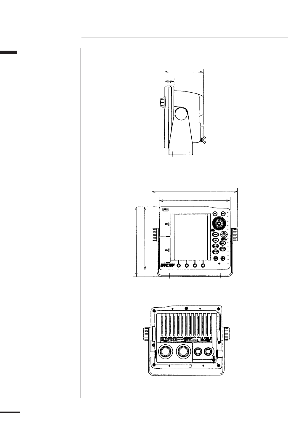
Section 1 Introduction
Construction
115 (4.5)
27 (1.1)
253 (10)
210 (8.3)
22
186 (7.3)
205.5 (8.1)
Unit : mm (inch)
Figure 1-2

450 ( 17.7)
200 (7.9)
260 (10.2)
Section 1 Introduction
227 (8.9)
(5.6)
141.4
92
(3.6)
15 (0.6)
141.4 (5.6)
Figure 1-3
178
(7)
200
( 7.9)
Unit : mm (inch)
23
Section 1 Introduction
System Configuration
SCANNER UNIT
SHIP’S MAINS
Figure 1-4
24
SECTION 2
Installation
Installing the Display Unit
Choosing a Location for Installation
CAUTION
This display unit produces heat. Do not install it in a
poorly ventilated or excessively hot area. Doing so
may cause burns or defects.
Do not install the equipment at a location where it is
constantly splashed with water. If the equipment is
splashed with water, immediately wipe with a dry
cloth. Leaving the equipment in this condition may
cause electric shock or malfunction.
The two most important considerations for mounting the RADAR 1800
Color Radar/Plotter display unit are:
•Choosing the best location for operating and viewing
•Protecting the unit from the environment
Standard Mounting
WARNING
Affix the Display Unit to a hard wooden or metal
plate with the specified screws when mounting it to
a tabeltop or suspending it. Otherwise the Display
Unit, weighting 2.8 kg may drop, causing injury or
damage.
Section 2 Installation
Typically the unit can be mounted with its yoke assembly to a chart tabletop
location. Figure 2-1 shows the recommended clearances for yoke mounting.
25
Section 2 Installation
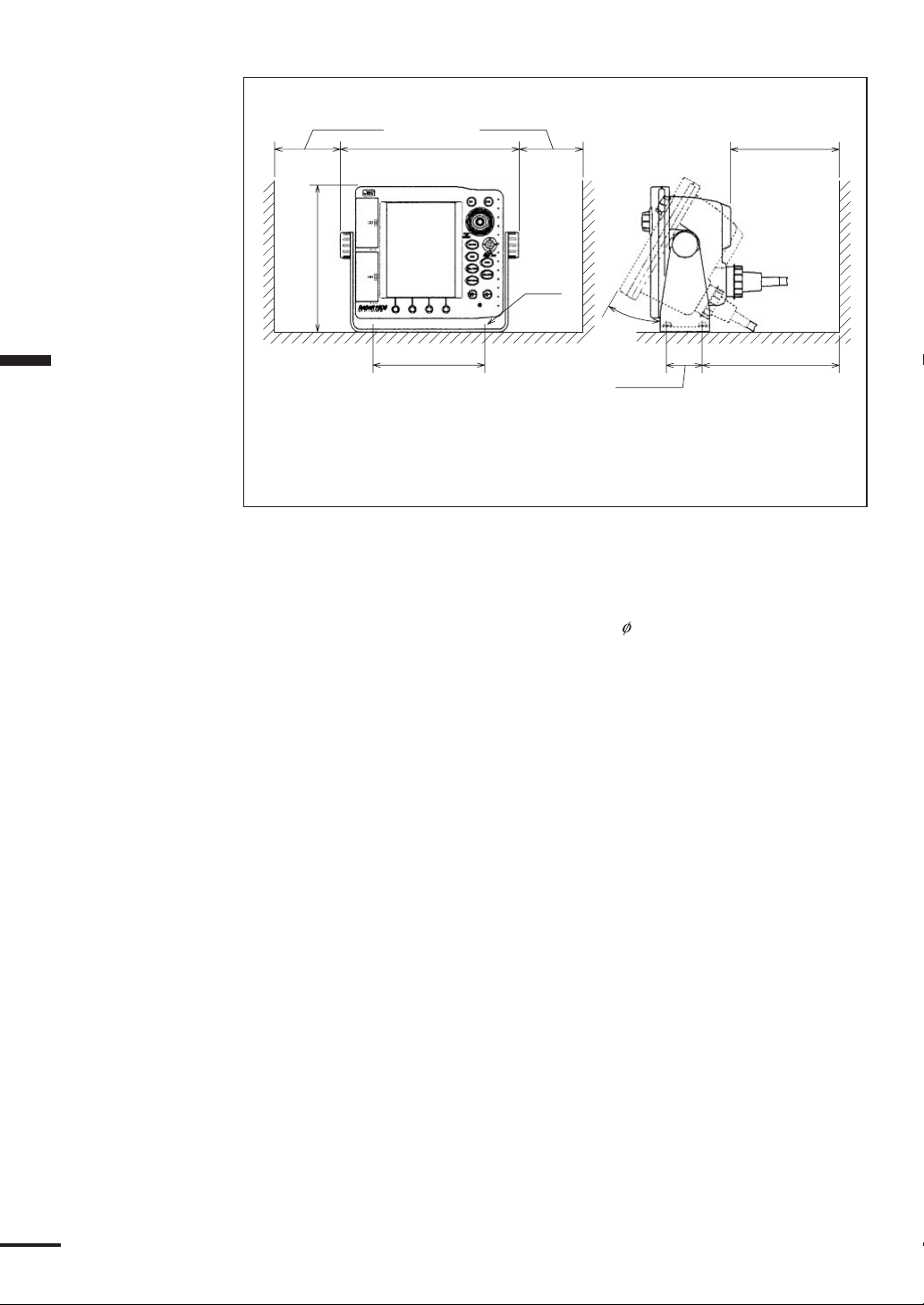
Unit : mm (inch)
RECOMMENDED CLEARANCES FOR YOKE MOUNTING
140 (5.5)
180 (7.1)
50 (2)
30°
80 (3.1) 80 (3.1)
253 (10)
205.5 (8.1)
150 (5.9)
M5
Figure 2-1
To mount the unit, remove the mounting yoke from the unit by loosening
the yoke knobs on each side of the RADAR 1800. Attach the bracket to the
desired mounting surface with the setting screws ( 5×25mmSUS, 4Qty.)
included in the kit, refering to Figure 2-1. Once the bracket has been mounted,
slide the unit back into its yoke. Adjust for the optium viewing angle and tighten
the yoke knobs.
26
Console Mounting/ Surface Mounting
ATTENTION
Make sure there are no hidden electrical wires or other
items behind the desired location before proceeding.
Also check that you have free access for mounting and
cabling.
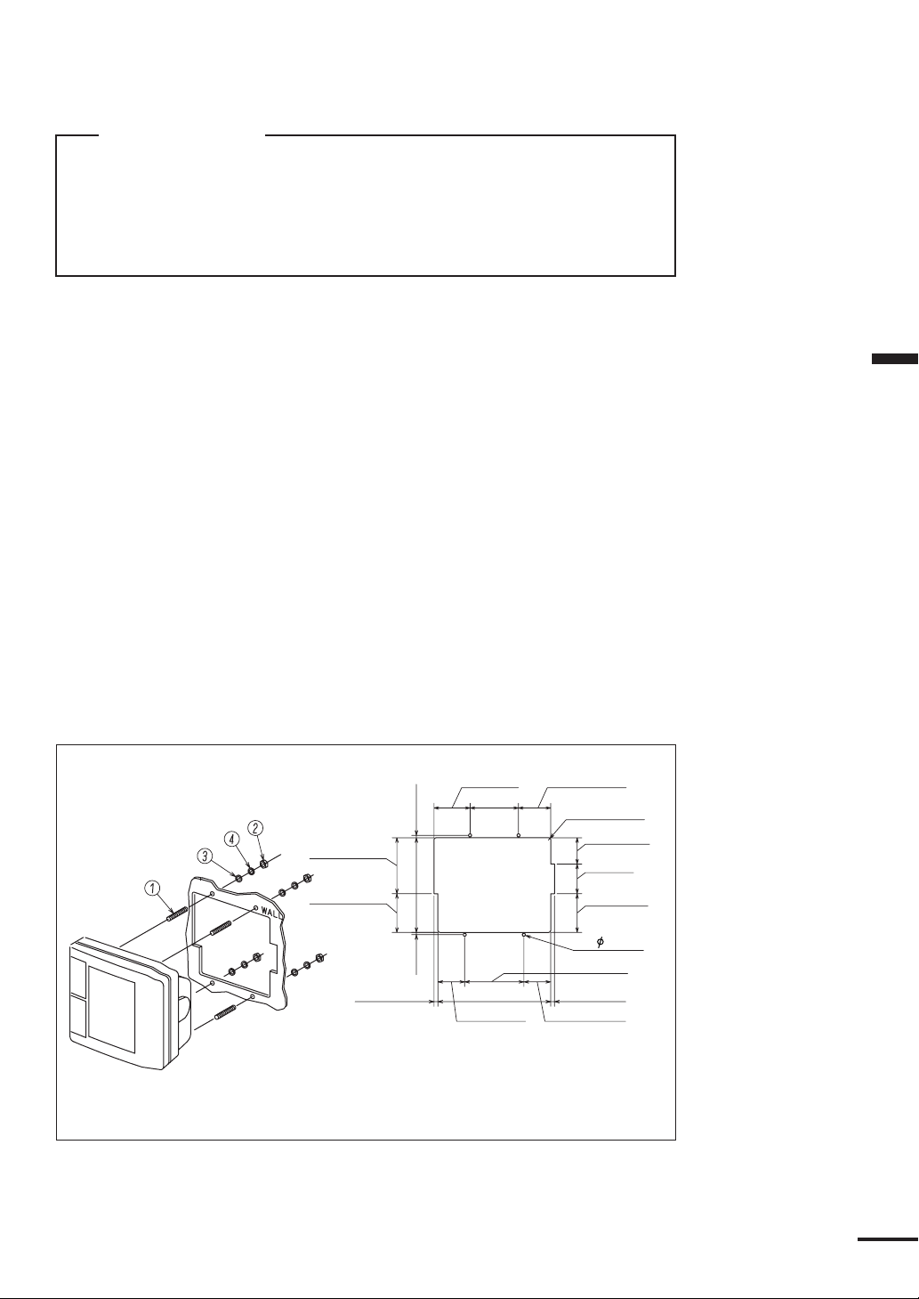
1) Select a mounting location: a clear, flat area of at least 8”(203mm) wide by 8”
high, having 5.5”(140mm) depth behind the panel. At that time, make sure
that there are no hidden electrical wires or other items behind your selected
location before proceeding.
2) Tape the mounting template from the console mounting instruction over your
selected location on the panel and trace around the edges.
3) Drill a 1/2”(12.7mm) pilot hole at the top and bottom of the cut-out area.
4) Cut along the outside edge of the cut-out line with an appropriate saw.
5) Drill holes, using a 1/5”(5mm) drill bit, for the four threaded screws, 2 on
each side, on the mounting template.
6) Remove the yoke, two knobs, two spacers and two damping rubbers from the
unit, then securely attach the threaded screws to the rear cabinet and verify
that the unit will fit inside the cut-out area.
7) Complete installation of the DC power, Scanner, GPS, NMEA and ground
wiring into the console and make the connections onto the rear of the unit.
8) Place the unit into the cut-out and fit the washers, lock-washers, onto the
threaded screws behind the mounting console, and tighten the nut to hold the
unit in place.
Section 2 Installation
1 SCREW
2 NUT
3 WASHER
4 LOCK WASHER
Illustration above shows the
way of Console Mounting.
94.5 (3.7)
65.5 (2.6)
Figure 2-2
61 (2.4)
82 (3.2)
4 (0.2)160 (6.3)
4
(0.2)
45.5 (1.8)
Illustration above shows the
cut-out size of the mounting
in the console.
54.5 (2.1)
4-R4 (0.2)
44.5 (1.8)
50 (2)
65.5 (2.6)
4- 5 ( 0.2)
100 (3.9)
6.5 (0.3)6.5 (0.3) 191 (7.5)
45.5 (1.8)
Unit : mm (inch)
27
Section 2 Installation
Installing the Scanner Unit
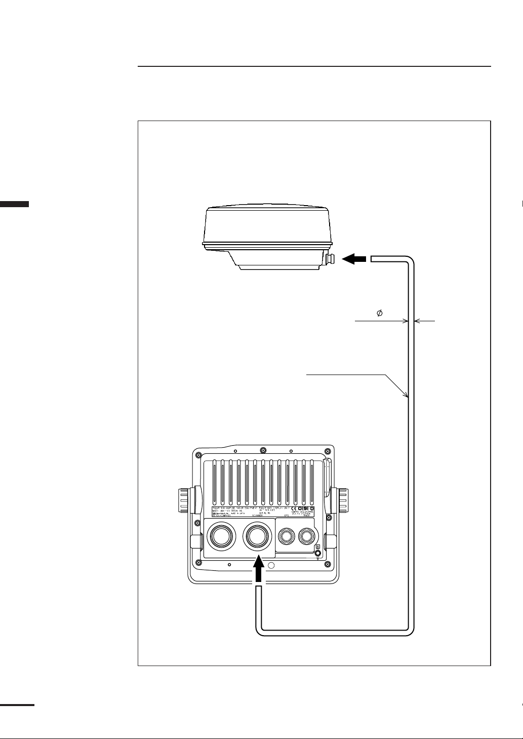
Connecting the Scanner Unit Cable
Connect the scanner unit cable as follows.
CAUTION
Be careful not to injure your finger or hand by the waterproof cap mounting
groove when installing the Display connector.
MAX 9.8
8-CORES
COMPOSITE CABLE
10 m : CFQ6531-10
15 m : CFQ6531-15
20 m : CFQ6531-20
28
Unit : mm
Figure 2-3
Installing the GPS/DGPS Sensor
Selecting the Position for Installation
CAUTION
When connecting the cable attached to the
equipment, do not bend to an acute angle, twist, or
impart excessive force. Doing so may damage the
cable and cause a fire or an electric shock.
Do not install the equipment in a place with
excessive vibration. Doing so may cause the
equipment to drop or tip over resulting in injury or
defects.
ATTENTION
Install the equipment in a place without any
obstacle, in order to ensure that GPS signals can be
directly received from satellites without interference or
reflection of signals from surrounding objects. If
possible, select a place having the following
characteristics.
1 An open space that allows uniform reception of satellite signals.
2Far away from any of high power transmission antennas.
3Outside the radar beam range.
4Away from the Inmarsat antenna by not less than 5 meters and below
the level of its antenna.
5Away from the antenna of a VHF, MF/HF transmitter and a direction
finder by not less than 5 meters.
6Away from Magnet Compass by not less than 1 meter.
Section 2 Installation
If it is difficult to find an ideal site, select a place temporarily and install the
equipment. Conduct a test to make sure that the proper performance can
be obtained and then fix the equipment in position. If it is installed at an
improper place, reception may become intermittent, resulting in shorter
position fixing time and poorer position accuracy.
29

Section 2 Installation
NCD-4300 DISPLAY UNIT
P3
+12V
GND
GPS
DATA IN-
GPS
DATA IN+
GPS
DATA OUT
P4
NC
NMEA
DATA OUT+
NMEA
DATA IN-
NMEA
DATA IN+
NMEA
DATA OUT+
SHIP'S
MAIN+
SHIP'S
MAIN-
COMPASS
DATA IN+
COMPASS
DATA IN-
1A
2A
PW
VD
VDR
TIR/GSR
TI/GS
BZ/TUNI
TUNV
INTSW
P1
T.RED
T.BLK
YEL
GRN
BLU
WHT
P2
T.RED
T.BLU
GRN
COAX
SHLD
SHLD
WHT
YEL
T.ORN
CFQ-6532 (2m)
CFQ-6531-10/15
TO SHIP'S MAIN
TO GPS/MAGNETIC COMPASS
NKE-1065 SCANNER UNIT
T.RED
T.BLU
T.ORN
YEL
SHLD
COAX
SHLDSHLD
WHT
GRN
1A
2A
NC
TUNV
TI/GS
TIR/GSR
VD
VDR
BZ/TUNI
PW
30
Figure 2-4 Interconnection Diagram

Installation Procedure
Installation
CAUTION
Insluate the GPS/DGPS sensor case from ground.
Without insulation, a considerable amount of
current frow from ground to this equipment.
A considerable amount of current may cause
equipment damage.
The aluminum bottom of the GPS112/DGPS212 are designed so that it can
be installed on the navigation antenna mount unit or on an extension mast
conforming to 1” x 14 NPT standards. The aluminum casing is negative earth, so
a plastic mounting unit should be used to prevent any corrosive activity from
developing. The bottom of the receiver is provided with a slot to allow the
receiver cable to be pulled out to the side. This eliminates the need of pulling the
cable through the center of an extension mast.
When twisting on the receiver be careful not to damage the cable.
Avoid thread damage Grip and turn from the base
Figure 2-5 Installation
Section 2 Installation
When the cable is pulled through the
center of the extension mast, it is
recommended that RTV silicon sealant be
used to seal off the cable slot on the
bottom of the receiver to protect it from
the environment. When the cable is pulled
out through the slot, secure it in position
to protect it against damage due to
vibration. Then seal the slot on the receiver
bottom with the RTV silicon sealant.
Seal with
RTV
Figure 2-6 Appearance
The Wrap or
Tape Cable
31

Section 2 Installation
Belt fitting method
GPS/DGPS
Sensor
Cable
Plastic
Mounting
Unit
Do not coil the fitting
belt around the
aluminum base.
20mm
(Sensor case bottom
to Mast top)
Fitting belt
Mast
(ø26- ø50)
1. Loosen the fitting belt screw
with a screwdriver and
remove the clamp.
Clamp
Minus screw driver
2. Coil the fitting belt around
the mast as shown below.
3. Tighten the clamp screw
with a screwdriver.
Figure 2-7 Belt Fitting Method
ATTENTION
• Do not fasten the junction of connectors with the
fitting belt.
It may cause connector damage.
• Do not coil the fitting belt around the aluminum base.
The aluminum base will be scratched with the belt
and may cause corrosion.
32

Connecting DC Power
WARNING
Do not touch the ground terminal and vessel ground
on the display unit at the same time without the
ground terminal earthed. Otherwise, you may suffer
an electric shock.
CAUTION
RED to the positive.
BLACK to the negative.
Do not mistake the colors, as doing so will cause a
malfunction.
Your unit is intended for use on vessels with 12 VDC power systems and it
can operate as long as the DC supply is maintained between 10.2 and 16.0 VDC.
The supplied 6.5 foot power cable assembly should reach the source of DC
power.
Section 2 Installation
➔ On larger boats, route the power leads to the ship’s DC power distribution
panel. Connect to 10 amp or 10 amp (maximum) circuit breaker, as the unit is
fused at 10 amps.
➔ On smaller vessels connect the power leads directly to the main battery
isolation switch or breaker.
Avoid grouping the unit’s power connections with radar, radio, or Loran-C
power leads on the same circuit breaker. Separate the wiring as much as possible
from other devices to prevent electrical noise interference.
Although the unit’s power consumption is approx. 50 watts, if you need to
extend the power cable leads by more than 10 feet, increase the wire size of the
leads accordingly to minimize line losses. For runs of 20-35 feet, #10 AWG is
recommended.
➔ Connect the RED wire to the positive (+) source terminal as shown in Figure
2-8.
➔ Connect the BLACK wire to the negative (-) source terminal as shown in
Figure 2-8.
If the power leads are accidentally reversed, the in-line fuse will blow. If this
happens, recheck the polarity of the connections with a volt-meter (VOM) and, if
necessary, reverse the leads for proper connection.
Then, replace the fuse.
If the unit will not turn on and you suspect that you may have reversed the
power connections, check the DC power lines all the way back to the battery. If
the polarity is not correct, properly reconnect the leads and try again.
33

The unit is internally protected
from accidental reverse polarity.
Reversing the power leads will
not damage the unit, it will
simply not turn on.
Connect to GPS
compass or
magnetic compass
Scanner
(NKE-1065)
Section 2 Installation
CAUTION
Be careful not to injure
your finger or hand by
the waterproof cap
mounting groove when
installing the power cable.
10 amp fuse
BLACK
−
Figure 2-8
RED
+
Connector to
GPS/DGPS
Sensor
JRC type GPS112 or
DGPS212
Connect to
NMEA0183
Input/Output
Ship's Ground
System
34
Grounding the Display Unit
One very important requirement in installation of shipboard electronics is to
obtain the cleanest, noise-free environment possible so each piece of electronic
equipment can work to its best performance levels. This requirement is
accomplished by assuring a proper connection from each equipment to the ship’s
RF ground system. The ground provides a drain for shipboard noise transmission
and pickup.
A separate ground wire of # 10 or # 12 AWG (# 10 recommended) should be
connected from the ground terminal on the rear of the unit to the nearest
connection point of the ship’s ground system.
Normally, on a steel hull boat, a good clean connection to the hull provides a
sufficient ground. On a fiberglass or wood hull, connection to a ground plate or
to the engine block and other bonded groundwork should be acceptable.

Connecting GPS/DGPS Sensor or Making
NMEA0183 Data Connections (Option)
When displaying the latitude and longitude of your vessel on the screen, or
using the NAVIGATION mode, you are required to connect the optional
GPS112 or DGPS212 sensor to the RADAR 1800, or input the data of
navigational information in the NMEA0183 format from navigation equipment.
Connecting GPS112 or DGPS212 sensor
CAUTION
Only the GPS/DGPS sensors manufactured by JRC
can be connected directly to the GPS connector at
the rear panel. If those other than manufactured by
JRC are connected, the equipment may be damaged.
When using the GPS112 or DGPS212 sensor, connect the 5-pin antenna
connector attached to the signal cable of the sensor to the “GPS” connector at the
rear panel of the unit.
With this, it is possible to receive the necessary data of navigational
information from the GPS112 or DGPS 212 sensor. It is advisable, however, to
perform initial settings according to your conditions using the GPS SETTING,
DGPS SETTING menu of the unit for more precise navigational information.
Refer to p.91 and p.92 for the information about initial settings for each sensor.
Making NMEA0183 data connections
When receiving navigational data information in the NMEA0183 format
from navigation equipment other than this unit, you are required to make a
connecting cable using the 5-pin connector (model 6-282-5SG-325, CONXALL)
and connect it to the “NMEA” connector at the rear panel of the unit.
Connect the 5-pin connector and the connecting cable as shown in Figure
2-9.
Section 2 Installation
Data - OUTPUT
Locating Dot
Viewed from solder side of connector body
Data + OUTPUT
Data Input
Data Common
Figure 2-9
NMEA 0183 OUTPUT
NMEA 0183 INPUT
35

Section 2 Installation
The procedure to assemble the connector is as follows. Please refer to Figure
2-11.
q Feed the end of the cable through the backshell, rubber grommet and cou-
pling ring in the order and position drawn.
w Strip the cable as shown in Figure 2-10. Begin soldering the conductors to
the connector pins, as shown in the appropriate diagram for the NMEA
connectors. Verify that each connector is firmly soldered and that no stray
wires are shorting adjacent pins.
Diameter 6.4~6.9
(0.25~0.27)
4.8 (3/16)
12.7 (1/2) MAX
7.9
(5/16)
Unit : mm (inch)
Figure 2-10
e Slide the coupling ring over the body of the connector and beyond the
locking projections on each side, it may be necessary to rotate the ring
slightly for it to pass by the locking tabs.
r Push the rubber grommet forward as far as possible to seat it snugly against
the connector body.
t Push the backshell all the way forward. It must first compress the rubber
grommet, then be twisted over the (2) locking posts on the connector body.
This is a tight connection. For leverage it may be helpful to first insert and
lock the connector into its mating plug on the RADAR 1800 back panel.
GROMMET
BACKSHELL COUPLING RING CONNECTOR BODY
PIN
CONTACTS
36
Figure 2-11

Connecting Electronic Compass/ GPS
Compass (Option)
By connecting the NMEA-183 formatted output (HDM) or the optional
GPS Compass (JLR-10), the realtime and precise course information is input and
you can use more precise North-Up or Course-Up mode.
Connection
RED: Ship’s main
RED
BLK
YEL
GRN
CFQ-6532(Power Cable)
BLK: Ship’s main
YEL: Compass Data
GRN: Compass Data
From GPS Compass
or Magnetic Compass
Section 2 Installation
Figure 2-12
Initial Operation and Set-up
Inspection after Installation
After completing the installation and prior to energizing the equipment, it is
necessary to ensure that all steps of the installation were accomplished in
accordance with the instructions. Make sure that:
q The cables are not pinched or damaged.
w The allowed voltage is not exceeded and the polarity is correct.
e All bolts are tight.
r The power cable shields have been properly connected to Boat Main ground.
37

MENU
INSTALLATION
SIMULATION
INITIAL POS.
CLOCK ADJUST
DATE & TIME
RADAR ADJUST>
DATA IN/OUT >
UNITS >
CALIBRATION >
OPERATION >
Section 2 Installation
RADAR ADJUST
EBL BEARING
PRF SHIFT
BEARING
DISPLAY TIMING
TUNE PRESET
STC PRESET
OFF
N 0° 00.000’
E 0° 00.000’
00/00/0000
00:00
12HOUR
REL
20
0
561
32
57
Operating the INSTALLATION menu
To access this menu:
Press
MENU
Select INSTALLATION> by
key to display the MAIN menu.
Joystick
up/down, push
Joystick
. The
INSTALLATION menu is displayed.
This menu includes various settings required for installation, such
as the selection of the external data input method and unit, or the
initial setting of the radar initial adjustment or the GPS/DGPS
antenna. After installing the RADAR1800, use this menu to make your
settings.
RADAR SET UP
The RADAR ADJUST menu contains settings which should be
done at installation or after any repairs to optimize the performance of
the radar system. It is recommended that the radar be run in transmit
mode for at least 10 minutes before adjusting the Preset Tuning in order
to stabilize the transmitter circuit first. It is also recommended to adjust
the Preset Tuning first as the other adjustments will be easier to do after
that. If Preset tuning is not correct, then the Auto Tune may not work
or may not work correctly and receiving targets will be decreased or
eliminated. If Preset STC is up too high the loss of closer in targets will
occur. These are the 2 most important adjustments for viewing target
echos. Bearing alignment and Range (Timing) adjustments are
important for correct picture orientation and safety.
In the INSTALLATION menu, select RADAR ADJUST> menu
by
Joystick
The RADAR ADJUST menu is displayed.
up/down, push
Joystick
.
38
TUNE PRESET
40
TUNE PRESET
From the RADAR ADJUST menu move the
Joystick
to move the hiliter onto Tune Preset, then press the
to select it. The TUNE PRESET popup menu shows the tuning
condition. The bar graph in the bottom of the screen shows the relative
position of the adjustment control. Move the
Joystick
while watching the echo targets and the upper bar graph. The upper bar
graph should peak to the right at the same point where the targets show
as the largest. When you achieve the best adjustment, push the
Joystick
once to save it.
Per form this step after the radar has been transmitting for 10 minutes.
•Set the range scale to 3 NM.
•Turn SEA and RAIN all the way down.
•Turn IR off.
•Set gain to a level just below the level where noise specks show on the
screen.
•In the RADAR ADJUST menu, select TUNE PRESET by
up/down, and push
Joystick
.
The TUNE PRESET pop-up menu is displayed.
•Move the bar by
Joystick
right/left to get the strongest signal back.
up or down
Joystick
one time
right or left
Joystick

BEARING
0
DISPLAY TIMING
840
STC PRESET
57
Note:
There may be 2 positions where the targets are strong. Select the one that
has the larger value of “TUNE PRESET”.
•Push the
Joystick
to save and exit.
Relative BEARING alignment
This adjustment should be performed after installation or a master
reset to avoid incorrect bearing readouts and picture orientation. Using
the 1.5 NM range, identify a small target such as a boat or buoy that
can be seen both visually and on the radar. Point the boat so the target
is visually dead ahead. If the radar target does not also show on the
heading line proceed with this adjustment. In the Radar Adjust menu
select BEARING by
Joystick
selecting by pushing the
Line (EBL) by
Joystick
be dead ahead. Push the
and push the
Joystick
again to rotate the picture by the offset just
up/down, moving the hiliter, and
Joystick
. Move the dashed Electronic Bearing
left/right to bisect the radar target that should
Joystick
once. Move the EBL to dead ahead
indicated.
DISPLAY TIMING
This step must be performed. Failure to perform this step may
result in incorrect target distance reading.
•Set the range scale to 0.25 NM.
• Locate a pier, a jetty, a bridge (close to water line) or any other straight
object. Position the vessel so that it appears on the display. It does not
matter which way you are facing.
•In the RADAR ADJUST menu, select DISPLAY TIMING by
Joystick
up/down, and push
Joystick
The DISPLAY TIMING pop-up menu is displayed.
•If the bridge, pier or jetty does not appear to be in a straight line on
the display, then the DISPLAY TIMING needs to be adjusted.
•Use the
Joystick
right/left to adjust the timing and make the object
appear straight on the display.
•Press
Joystick
when done.
.
Section 2 Installation
STC PRESET
This step must be performed. Failure to perform this step may
result in incorrect sea clutter suppressing.
•Set the range scale to 6 NM.
•Turn IR off, STC to maximum, and set gain to maximum.
•In the RADAR ADJUST menu, select STC PRESET by
up/down, and push
Joystick
The STC PRESET pop-up menu is displayed.
•Use the
•Press
Joystick
Joystick
to remove all background noise from 0-3 NM.
when done.
.
Joystick
39

Section 2 Installation
Connecting Personal Computer
Connect the RADAR 1800 to a personal computer as follows in order to
transfer data between them.
Cable connection
Personal computer RADAR 1800
CD (1) NC (1)
RD (2) RD (2)
TD (3) TD (3)
DTR (4) NC (4)
SG (5) SG (5)
DSR (6) NC (6)
RTS (7) RTS (7)
CTS (8) CTS (8)
RI (9) NC (9)
Signal specification
RS-232C
BAUD RATE 38,400 bps
40

Inserting a Chart Card
This electron
used only
official gove
chart and
navigation
q Check that the card is C-MAP NT C-Card with the required chart stored on
it.
w Open the card cover, at the higher left of the display front panel.
e Hold the card with the title label towards the left and upside down, as shown
in the illustration.
r Gently push the card into one of the two slots. It will only go in if it is the
correct way round. Push the card in as far as it will go, then move it to the
right so that the top is under the retaining pegs. The card will be held in
place by the pegs.
t Close the card cover so that it clicks shut, to prevent water from entering the
display unit.
M
O
T
T
O
P
U
S
H
O
P
E
N
B
Section 2 Installation
Figure 2-13
Removing a Chart Card
q Open the card cover, at the higher left of the display front panel.
w Push the card in to disengage from the pegs, then remove it.
e Close the card cover so that it clicks shut, to prevent water from entering the
display unit.
Note:
•Turn off the power when removing the chart card.
Removing the chart card when the chart is being updated may cause an erroneous
chart to be displayed. If an erroneous chart is displayed, do enlarge/reduce and redisplay the chart.
41

SECTION 3
Screen Layout
Operation
Section 3 Operation
SHIP POSITION
OWN SHIP ICON
RANGE SCALE &
RANGE RING
INTERVAL
VIDEO PROCESS
Trail interval
TARGET
EXPANDER
INTERFERENCE
REJECTION
HEADING LINE
VRM
DATE & TIME
BEARING MODE
EBL & VRM
N 35° 41.054'COG185.7° GPS
W139° 34.472'SOG 0.0KTS
PROC1
T
EXP
IR
APR09 04:11A
N 35 41. 54'
E 139 34.472'
EBL
.
1M
3
5
25.01.21
R
HUP
CURSOR INFORMATION
(Position, Bearing & Distance)
VRM
NM
BRG 0.0
RNG 0.00NM
COURSE & SPEED
VRM
S
R
G
AUTO
T
GZ
04
GPS STATUS
JOG-DIAL
FUNCTION
LEVEL
S: SEA
R: RAIN
G: GAIN
T: TUNE
GUARD ZONE
(Mode & Level)
EBL
RANGE RINGS
42
Figure 3-1 Radar mode

No. ITEMS Displaying symbols
q OWN SHIP ICON Selected own ship ICON.
w SHIP POSITION Ship position is available when used with GPS/
DGPS sensors or NMEA0183 format data is
received.
e COURSE & SPEED COG (the ship’s course over the ground) and
SOG (the ship’s speed over the ground) appears.
r GPS STATUS DGPS : Differential GPS fix.
DGPS-W : Differential GPS fix (WAAS TYPE)
GPS : GPS fix.
NO FIX : Fix not available or invalid.
NO DATA : No position data input.
(NO GPS/DGPS sensor connected)
t
RANGE SCALE & RANGE RING INTERVAL
y VIDEO PROCESS Radar video processing type.
u TRAIL INTERVAL Trail interval and condition.
i TARGET EXPANDER Target expander.
o INTERFERENCE REJECTION Radar interference rejection. (IR)
!0 BEARING MODE Azimuth stabilization mode with symbol.
!1 EBL & VRM Numerical display EBL and VRM.
!2 JOG-DIAL FUNCTION Selecting JOG-DIAL.
!3 LEVEL indicator “AUTO” is displayed in automatic mode.
!4 GUARD ZONE Guard zone.
!5 HEADING LINE Ship’s heading line.
!6 VRM VRM display. (Variable Range Marker)
!7 EBL EBL display. (Electric Bearing Line)
!8 RANGE RINGS Range ring display.
!9 DATE & TIME Month/Day Hour/Minute
@0 CURSOR INFORMATION LAT/LON of the cursor, the distance between the
Used range scale and range ring interval.
OFF : No process. (No title display)
PROC1 : Processing type 1.
PROC2 : Processing type 2.
PROC3 : Processing type 3.
OFF : No trail. (no title display)
0.5 - 6 : Trail interval. (Unit: min)
CONT : Continuous trail.
OFF : No expansion. (No title display)
ON : Target expansion.
OFF : IR off. (No title display)
ON : IR on.
HUP : Head up.
NUP : North up.
CUP : Course up.
(NUP and CUP mode needs heading data)
(SEA/RAIN/GAIN/TUNE/EBL/VRM)
Mode : IN/OUT alarm.
Level : Threshold level.
vessel and the cursor, the bearing of the cursor
appear.
Section 3 Operation
43

SHIP POSITION
N 42° 34.255'COG122.3° DGPS
W122° 19.487'SOG 25.5KTS
COURSE & SPEED
N 43° 17.181'
W124° 24.215'
BRG 295.8°
RNG 2426NM
GPS STATUS
CURSOR
INFORMATION
Section 3 Operation
Figure 3-2 Plotter mode
No. ITEMS Displaying symbols
q SHIP POSITION
w COURSE & SPEED
e GPS STATUS
r CURSOR INFORMATION
Ship position is available when used with GPS/DGPS
sensors or NMEA 0183 format data is received.
COG (the ship’s course over the ground) and
SOG (the ship’s speed over the ground) appears.
DGPS : Differential GPS fix. (Beacon TYPE)
DGPS-W : Differential GPS fix (WAAS TYPE)
GPS : GPS fix
NO FIX : Fix not available or invalid
NO DATA : No position data input (No GPS/DGPS
sensor connected)
LAT/LON of the cursor, the distance between the
vessel and the cursor, the bearing of the cursor appear.
The information about the cursor can be selected whether
or not to display. (Refer to “CURSOR INFO” p.91)
44

Control Panel
Figure 3-3 shows the panel keys and their functions.
!4
!5
PUSH
OPEN
C-MAP CARD
PUSH
OPEN
PC I/F PORT
1800
RADAR
COLOR LCD RADAR-PLOTTER
PUSH
SELECT
MOB
RANGE
NAV
EBL/VRM
BRT/CLR
STBY
OFFTXOFF
MENU
PUSH
EVENT/ENT
MODE
CENTER
q
w
e
r
t
y
u
i
o
!0
!1
!2
!3
Figure 3-3
Control Panel
No. Keys Functions
q MOB Man Over Board
w MENU Push to display the menu.
e JOG-DIAL Push and turn: Select function and adjust level.
Push: Select SEA, RAIN, GAIN, TUNE controls
repeatedly.
In AUTO mode, skip SEA or TUNE control.
Turn: SEA: reduces sea clutter.
RAIN: reduces rain or snow clutter.
GAIN: controls strength of returned echoes.
TUNE: manually fine tunes receiver by peaking
tuning bar.
No tuning bar in AUTO tune mode.
EBL: rotate EBL to CW or CCW
VRM: increase or decrease VRM
BRIGHT: used to adjust display backlighting.
CONTRAST: used to change LCD contrast
setting for best visual display.
Section 3 Operation
45

Section 3 Operation
STBY/OFF
TX/OFF
STBY/OFF
TX/OFF
No. Keys Functions
r RANGE Sets range scale by SOFT Key.
t JOY-STICK Position cursor setting.
Up/Down/Right/Left: Selects and changes an item when each
menu is displayed.
Push: Fixes the set value when each menu is displayed.
Enters a marker when no menu is displayed.
Registers EVENT in the NAVIGATION mode.
y NAV Executes or stops navigation to the desired waypoint or of the
planned route.
u MODE Switches among the Radar and Plotter mode displays.
i EBL/VRM Activates EBL or VRM on the display.
A short press will turn on/off selected EBL/VRM.
Press and hold, to select and control the desired EBL or VRM by
or
STBY/OFF
STBY/OFF
Jog Dial
Jog Dial
and
and
.
.
TX/OFF
TX/OFF
keys simultaneously to turn off.
keys simultaneously to turn off.
rotating the
o CENTER To shift own ship on radar screen in Radar mode and Radar/
Chart mode.
!0 BRT/CLR Press and hold, set the brightness or contrast of the LCD with
Joystick
Acknowledge of alarm.
Abort setting value.
!1 TX/OFF Turns transmitter ON and activates Radome.
Press
!2 STBY/OFF Turns ON power to Display and Scanner and activates 90 second
count-down timer.
Press to go into Stand-by mode while in the Transmit mode.
Press
!3 Soft Keys Correspond to Soft Keys displayed at the bottom of the screen.
There may appear up to four Soft Keys according to the displayed
screen.
!4 Card Slot A built-in world map is available on C-MAP electronic chart.
(C-MAP Card) Card slot available for more detailed local C-Map charts.
!5 PC I/F Port Connect a personal computer for saving and loading navigation
data and user settings.
46

Rear Panel
q
w
e
r
yuiot
Figure 3-4
Rear Panel
No. ITEMS Function
q Spacers
w Yoke Knobs
e Damping rubbers
r Yoke mount
t GROUND terminal Connects GROUND.
y NMEA connector Connects NMEA0183 format data
u GPS connector Connect GPS/DGPS SENSOR
* Connectable JRC’s GPS/DGPS sensor only.
(Refer to p.35)
i SCANNER connector Connects the scanner.
o
DC12V / COMPASS connector
Connects power supply and magnetic/GPS compass.
Section 3 Operation
47

Section 3 Operation
Basic Operations
When you turn the power of the RADAR 1800 on, the initial
screen appears.
RADAR 1800
COLOR RADAR/PLOTTER
NOTICE
THIS DEVICE IS ONLY AN AID
TO NAVIGATION AND IT IS
THE USER'S RESPONSIBILITY
TO EXERCISE COMMON PRUDENCE
AND NAVIGATIONAL JUDGEMENT.
THIS DEVICE SHOULD ALWAYS
AND ONLY BE USED IN
CONJUNCTION WITH UPDATED
GOVERNMENT CHARTS.
OPERATION TIME 0H
TX TIME 0H
SOFTWARE VERSION:R3.00
COPYRIGHT 2000-2002
After approx. 15 seconds, the count down timer appears in Radar
full screen.
48

10
5
BRIGHT/CONT
The Power Control (Turning the
STBY/OFF
TX/OFF
STBY/OFF
STBY/OFF
TX/OFF
STBY/OFF
TX/OFF
STBY/OFF
TX/OFF
T/CLR
MODE
Radar ON and OFF)
• Push
• Push
• Push
• Push
STBY/OFF
TX/OFF
STBY/OFF
STBY/OFF
once to turn the power on.
to transmit.
to enter the stand-by mode.
TX/OFF
and
simultaneously to turn the power off.
When you:
• Push
• Push
STBY/OFF
TX/OFF
a 90 second warm-up count down timer is activated.
the radar transmits, the scanner begins to rotate and
echoes will appear on the screen.
• Push
STBY/OFF
the radar returns to stand-by mode to reduce battery
drain. The rotator stops.
• Push
TX/OFF
again, the radar reverts to full transmitting function.
LCD Backlight and Contrast
Control
• Push and hold
BRIGHT/CONT menu. Press the
brightness or contrast. The selected item is highlighted. Press the
Joystick
Push the
If you make no operation for 7 seconds, the menu closes
automatically.
BRBRT/CLR
approximately 2 seconds to display the
Joystick
up or down to select
to the left or right to adjust the brightness or contrast level.
Joystick
to complete the adjustment, and the menu closes.
Section 3 Operation
Display Modes
Press
MODE
to switch among the Plot mode screens.
N 35° 41.054'COG185.7° GPS
W139° 34.472'SOG 0.0KTS
EBL
3
25.0 1.21
R
.
5
HUP
PROC1
1M
T
EXP
IR
APR09 04:11A
N 35 41. 54'
E 139 34.472'
VRM
NM
BRG 0.0
RNG 0.00NM
VRM
S
R
G
AUTO
T
GZ
04
RADAR RADAR/CHART
N 42° 34.255'COG 92.5° DGPS
W122° 19.487'SOG 25.5KTS
HDG
82.5
COG
92.5
SE
AWS
13.4
OFF COURSE SHALLOW
VMG
STW
S
E
KTS
SOFT
KEY
SOG
°
T
VMG
°
T
SW
AWA
72
3
TWD
NE
SOFT
KEY
°
°
25.5
12.3
W
N
12.3
SOFT
KEY
KTS
OG
KTS
NW
TWS
KTS
N 42° 34.255'COG 92.5° DGPS
W122° 19.487'SOG 25.5KTS
N 42° 34.255'COG 92.5° DGPS
W122° 19.487'SOG 25.5KTS
HDG
82.5
COG
92.5
BRG
72.5
WPT
001 ABCDEFGH
ETA
21 OCT 10:54AM
°
T
°
T
°
T
SOG
STW
DPT
XTE
25.5
20.3
69.3
RNG
15.7
KTS
KTS
FT
NM
0.02
VESSEL POSITION
21 OCT 8:28AM
N 4 2 ° 5 1 . 8 1 8 '
W 8 7 ° 5 1 . 1 3 6 '
OFF COURSE SHALLOW
SOFT
SOFT
SOFT
KEY
KEY
KEY
SOFT
KEY
N 42° 34.255'COG 92.5° DGPS
W122° 19.487'SOG 25.5KTS
CHART
N 42° 34.255'COG 92.5° DGPS
W122° 19.487'SOG 25.5KTS
COG
92.5
WPT
001 ABCDEFGH
0.1 0.1
SOG
25.5
OFF COURSE SHALLOW
SOFT
KEY
SOFT
KEY
BRG
°
T
00.02
DPT
KTS
SOFT
KEY
72.5
RNG
15.7
69.3
SOFT
KEY
CDI/COMPASSNUM DATAWIND DATA
°
T
NM
FT
49

Press Soft Key, there may appear the following Soft Keys.
CHART
FULL
Changes the screen to the full chart screen.
N 35° 41.054'COG185.7° GPS
W139° 34.472'SOG 0.0KTS
Section 3 Operation
RADAR
FULL
DGPS
INFO
CENTER
Changes the screen to the full Radar screen.
Changes the screen to the DGPS status screen. Press the
Soft Key again to return to the previous screen.
Redisplays the screen so that your vessel appears at the
center of the chart in the chart screen.
RADAR Mode
Select RADAR to display the radar on the full screen.
N 42° 34.255'COG 92.5° DGPS
W122° 19.487'SOG 25.5KTS
50
RADAR/CHART Mode
Select RADAR/CHART to display the radar/chart on the split screen.

CHART Mode
N 42° 34.255'COG 92.5° DGPS
W122° 19.487'SOG 25.5KTS
OFF COURSE SHALLOW
SOFT
KEY
SOFT
KEY
SOFT
KEY
SOFT
KEY
N 42° 34.255'COG 92.5° DGPS
W122° 19.487'SOG 25.5KTS
WPT
001 ABCDEFGH
RNG
NM
15.7
COG
°
T
92.5
BRG
°
T
72.5
00.02
DPT
FT
69.3
SOG
25.5
KTS
0.1 0.1
Select CHART to display the chart on the full screen.
Course Deviation Indicator (CDI)/COMPASS Mode
Select CDI/COMPASS to display the navigation full screen display. The
navigation display includes the numerical data, compass window and
highway window. Three types of information are displayed at the same
time. The numerical data includes such information as water depth, vessel
speed, course, and your vessel’s position. The compass window indicates
the relation between your vessel’s course and the destination. The
highway window indicates your vessel’s position relative to the course. To
display the information mentioned above, however, it is necessary to
connect a GPS/DGPS sensor (optional) and Navigation.
Section 3 Operation
Navigation mode displays data
[Highway window]
Waypoint marker
[Compass window]
Vessel course marker
CDI range
Vessel position marker
(deviation from course)
Bearing marker Vessel heading marker
51

Section 3 Operation
[Numeric Data]
DPT :Depth
SOG : Speed (Over Ground) (unit: KTS=knots, KPH=km/hour,
MPH=mile/hour)
WPT: Waypoint ID
COG:Vessel course over ground (unit: degree/ T=true,
M=magnetic)
BRG :Bearing to destination (unit: degree/ T=true, M=magnetic)
RNG: Distance to destination (unit:0.1 NM)
XTE : Cross track error. Deviation from course and direction to
steer (unit:0.1 NM)
Steering required to return to the planned course is indicated
t (Left) and s (Right)
Notes:
•To display the vessel heading marker and HDG (Vessel heading), it is
necessary to receive the vessel heading data in the NMEA0183 standard
format. You need to connect the specified signal line to the NMEA
connector or DC12V/ COMPASS connector on the rear panel to receive
the vessel heading data.
•To display the water depth data, it is necessary to receive the depth data in
the NMEA0183 standard format. You need to connect the specified signal
line to the NMEA connector on the rear panel to receive the water depth
data.
N 42° 34.255'COG 92.5° DGPS
W122° 19.487'SOG 25.5KTS
HDG
82.5
COG
92.5
BRG
72.5
WPT
001 ABCDEFGH
ETA
21 OCT 10:54AM
°
T
°
T
°
T
XTE
SOG
25.5
STW
20.3
DPT
69.3
RNG
KTS
KTS
FT
15.7
NM
0.02
VESSEL POSITION
21 OCT 8:28AM
N 4 2 ° 5 1 . 8 1 8 '
W 8 7 ° 5 1 . 1 3 6 '
OFF COURSE SHALLOW
SOFT
SOFT
SOFT
KEY
KEY
KEY
SOFT
KEY
NUM DATA Mode
Select NUM DATA to display the numeric display. The numeric
display includes the numerical data of various navigation information
such as water depth, vessel speed, course, heading direction, deviation
from the course, your vessel’s position, and so on. To display the
information mentioned above, however, it is necessary to connect a
GPS/DGPS sensor (optional) and activate Navigational equipment.
Notes:
•To display the vessel heading marker and HDG (Vessel heading), it is
necessary to receive the vessel heading data in the NMEA0183 standard
format. You need to connect the specified signal line to the NMEA
connector or DC12V/ COMPASS connector on the rear panel to receive
the vessel heading data.
•To display the water depth data, it is necessary to receive the depth data in
the NMEA0183 standard format. You need to connect the specified signal
line to the NMEA connector on the rear panel to receive the water depth
data.
•To display the speed through the water (STW), it is necessary to receive the
speed through the water data in the NMEA0183 standard format. You
need to connect the specified signal line to the NMEA connector on the
rear panel to receive the water speed data.
52

WIND DATA Mode
MENU
MENU
OFF COURSE SHALLOW
SOFT
KEY
SOFT
KEY
SOFT
KEY
N 42° 34.255'COG 92.5° DGPS
W122° 19.487'SOG 25.5KTS
HDG
°
T
82.5
SOG
KTS
25.5
AWS
KTS
13.4
TWS
KTS
12.3
COG
°
T
92.5
N
W
E
S
SE
SW
NW
NE
AWA
°
72
TWD
°
3
VMG
KTS
OG
12.3
VMG
STW
To display the wind display with numerical data, it is necessary to
receive the wind direction/speed data and the vessel reading/course data
from external navigation aids.
Notes:
•To display the wind data, it is necessary to receive the wind data in the
NMEA0183 standard format. You need to connect the specified signal
line to the NMEA connector on the rear panel to receive the wind data.
•Skipped WIND Mode if there is no wind data.
Vessel’s Information/Waypoint’s
Information
•Press
to display the following menu. Press soft Key 1 and
MENU
the status at the top of the screen changes. To change to the next
status, push
MENU
Key 1.
VESSEL
INFO 1
(Soft Key 1)
VESSEL
INFO 1
Information about your vessel’s position, course, speed,
and the GPS/DGPS status is displayed.
N 42° 34.255'COG122.3° T DGPS
W122° 19.487'SOG 25.5KTS
VESSEL
INFO 2
Information about your vessel’s course, speed, tripped
distance, water temperature, and the GPS/DGPS status
is displayed.
COG122.3° T TRIP 25.8NMDGPS
SOG 25.5KTS TEMP 17.5°C
Note:
•Temperature data is displayed when received the water temperature data
from an external water temperature gauge.
VESSEL
INFO 3
COG122.3° DEP DGPS
SOG 25.5KTS
Note:
•Information about the depth of the water is displayed when it has been
attained.
Information about your vessel’s course, speed, water
depth, and the GPS/DGPS status is displayed.
again, and it can be changed by pressing Soft
GRAPH
FIND
ON
(Soft Key 2) (Soft Key 3) (Soft Key 4)
9999.9
FT
Section 3 Operation
53

WPT
T/CLR
INFO 1
Information about the position, direction, and distance
of a waypoint and the GPS/DGPS status is displayed.
N 42° 34.255' BRG122.3° TDGPS
W122° 19.487' RNG 5.5NM
Section 3 Operation
FIND ITEMS
NEAREST PORT
PORT BY NAME
TIDE STATION
WAYPOINT
WPT
INFO 2
Information about the name, and distance of a waypoint,
the estimated time of arrival, and the GPS/DGPS status
is displayed.
SEATLE ETA 9:45ADGPS
RNG 5.5NM 21 OCT
Graph Display
GRAPH
ON
You can display a one-hour history of changes in the
graphs for water temperature, depth, and ship’s speed by
using these soft keys.
Select the item to display beforehand in GRAPH
DISPLAY in THE GRAPH SETTING MENU. (Refer
to p.87)
Press the
BRBRT/CLR
key to delete the graph.
Finding Function
FIND
Nearest port
•Search for the port that is nearest to your boat or nearest to the cursor.
Port by name
•Search for a port that includes a specified name, a maximum of ten
ports are listed.
•By specifying the target port on the list, a chart of that port’s
surrounding area is displayed.
By using this function you can easily find your
destination as well as the nearest port and tidal station.
54
Tidal station
•Search for the tidal station that is closest to the cursor or to your boats
present position, a maximum of ten tidal stations are listed.
•By specifying the target tidal station on the list, that sector’s tidal
graph is displayed.
Waypoint
•Displays a list of destinations.
•By specifying the target destination on the list, a chart of that
destination’s surrounding area is displayed.

Using the Jog Dial
•Push and turn: Select function and adjust level.
Push: Select SEA, RAIN, GAIN, TUNE controls repeatedly. In
AUTO mode, skip control.
Selected control is displayed highlighted.
Turn: SEA: reduces sea clutter. No bar in Auto
mode.
RAIN: reduces rain or snow clutter.
GAIN: controls strength of returned echoes.
TUNE: manually fine tunes receiver by peaking
tuning bar. No tuning bar in AUTO
tune.
EBL: rotate EBL to CW or CCW
VRM: increase or decrease VRM
BRIGHT: Adjusts display backlighting.
CONTRAST: Adjusts the LCD contrast level.
Using the Joy Stick
Normally use the
to use the menus. Or press the
• Position cursor setting.
• Up/Down/Right/Left: Selects and changes an item when each menu
• Push: Fixes the set value when each menu is
Joystick
to move the cursor (8 directions) and
Joystick
to do the following.
is displayed.
displayed.
Enters a marker when no menu is displayed.
Registers EVENT or WAYPOINT in the
CHART mode. (Refer to p.71)
Section 3 Operation
Changing CURSOR Operation in
RADAR/CHART Mode
• Press and hold
to another screen in RADAR/CHART mode.
• The color of cursor is white in the RADAR screen and black in the
CHART screen.
Joystick
approximately 2 seconds to jump the cursor
General MENU Operation
Following the basic operation described below, you can easily perform
all menu operations using only the
Selecting an item:
• Press the
complete the selection. When you select a normal item, the pull-down
menu of the selected item opens. Select an item with ‘>’ mark to
display the submenu in the next hierarchy.
Joystick
up or down to select an item and push it to
Joystick
.
MENU
RADAR SETTING>
PLOT SETTING >
GRAPH SETTING>
GPS SETTING >
DGPS SETTING >
WAAS SETTING >
INSTALLATION >
CUSTOM SETUP >
MEMORY COPY >
ALARM SETTING>
EDIT >
55

Changing settings:
T/CLR
MENU
MENU
T/CLR
MENU
STBY/OFF
MOB
MENU
• When settings are specified by numerical values, press the
up or down to change the values. When settings are specified by bar
chart or by other items, press the
Joystick
to the left or right to
change the settings.
Joystick
Entering changes:
• Push the
change, push
You can display the top Menu by pressing the
Pressing the
Joystick
MENU
to enter the change. If you want to cancel the
BRBRT/CLR
before completing it.
again or
BRBRT/CLR
MENU
key.
closes the menu.
BUZZER
OFF ON
MASTER RESET
Section 3 Operation
SELECT YOUR LANGUAGE.
ENGLISH
FRANCAIS
DEUTSCH
ITALIANO
NORSK
ESPANYOL
MASTER RESET
SELECT RESETTING TYPE.
SOFT
HARD
SOFT:
INITIALIZE ALL SETTINGS
WITHOUT CLEAR WPT&ROUTE
DATA
HARD:
INITIALIZE ALL SETTINGS
WITH CLEAR WPT&ROUTE DATA.
Buzzer ON/OFF
Joystick
MENU
, select the “ALARM SETTING>” and push the
, the “ALARM SETTING” menu is displayed.
Joystick
, the “BUZZER” pop-
Joystick
to right or left.
• Press
Select the “BUZZER” and push the
up menu is displayed.
Change settings to ON/OFF by pressing the
Setting LANGUAGE
Joystick
STBY/OFF
MENU
to turn the power on while pushing
at the same time, the MASTER RESET
Joystick
Joystick
up or down to select HARD or
up or
to the left or right to select OK and push it in to
Joystick
.
• When you push
MOB
and
display and you can select your language. Press the
down to select a language and push it in to open MASTER RESET
type select display. Press the
SOFT and push it in to select OK or CANCEL for the select
language and the reset type.
Press the
excute the MASTER reset. After the MASTER reset is executed, the
RADAR 1800 is rebooted automatically. To abort the MASTER reset,
select CANCEL and push the
(Refer to “Master Reset and Language Select Operation” p.110)
56
MASTER RESET
YOUR SELECTS
ENGLISH
SOFT RESET
EXECUTE MASTER RESET.
ARE YOU SURE?
OK CANCEL

Radar Operation
RANGE
RANGE
All radar functions operates only in the RADAR full screen or in
the RADAR/CHART screen. If any other screen mode is selected the
radar will be put into standby mode.
Selecting a RANGE
[RADAR full screen mode]
•Press
RANGE
to display two Soft Keys.
RANGE
-
RANGE
-
RANGE
+
The range rings are automatically set to correspond with this selection.
[RADAR/CHART screen mode]
•Press
ZOOM
IN
ZOOM
IN
ZOOM
OUT
Decrease the range scale. The minimum range scale is
0.125NM.
Increase the range scale. The maximum range scale is
24nm.
RANGE
to display four Soft Keys.
ZOOM
OUT
Magnify the chart.
Reduce the chart.
RANGE
-
RANGE
+
RANGE
+
Section 3 Operation
RANGE
-
RANGE
+
The range rings are automatically set to correspond with this selection.
Decrease the range scale. The minimum range scale is
0.125 NM.
Increase the range scale. The maximum range scale is
24 nm.
57

Section 3 Operation
Adjusting Receiver Sensitivity
•Press the
corner of the display. Rotate the
counterclockwise, to vary the gain and thus control the strength of
echo returns on the radar screen.
An on-screen bar indicates the gain level selected. The proper setting
is when the background noise is just visible on the screen. (i.e. a light
speckled effect)
Jog Dial
until GAIN is highlighted in the upper right
Jog Dial
clockwise or
Adjusting TUNING
This procces is for Manual Tuning mode only. Manual Tuning can be
selected by MENU, RADAR SETTING, TUNE – Manual or
Automatic.
•Press the
corner of the display. Rotate the
counterclockwise, to maximize the target echo. If there is no large,
identifiable target (e.g. big ship or land) within range, select SEA
CLUTTER and turn the control to minimum. Use these echoes from
wave crests to adjust the tuning bar for fullest attainable deflection.
This is best done with the range set to 3 NM or 6 NM. An on-screen
bar indicates the manual tune is selected.
When the radar has warmed up, it may be necessary to make a further
fine tune adjustment.
Jog Dial
until TUNE is highlighted in the upper right
Jog Dial
clockwise or
AUTO TUNE
The RADAR 1800 has an automatic tuning feature. In this mode, the
radar automatically tunes itself for best efficiency at all ranges. (Refer to
p.63)
Reducing SEA CLUTTER
ATTENTION
The SEA CLUTTER control is normally only used
on the shorter ranges to suppress the effect of
sea clutter formed by breaking wave crests
which the radar "sees" as solid objects. An onscreen bar indicates the sea level selected.
If the Sea Clutter reduction is turned up too far,
small targets will be lost also.
•Press the
of the display. Rotate the
vary the sea clutter control and thus control the strength of echo
returns from the sea surface. The on-screen bar indicates the selected
level.
AUTO SEA
The RADAR 1800 has an automatic sea clutter control feature.
In this mode, the radar automatically suppress the effect of sea clutter.
(Refer to p.63)
Jog Dial
until SEA is highlighted in the upper right corner
Jog Dial
clockwise or counterclockwise, to
58

Adjusting RAIN CLUTTER
CENTER
CENTER
EBL/VRM
EBL/VRM
EBL/VRM
•Press the
corner of the display. Rotate the
counterclockwise, to vary the level and thus control the strength of
echoes returned from rain or snow.
An on-screen bar indicates the rain level selected. As you rotate
clockwise, the returned echoes will become narrower and the returns
from rain or snow will be reduced.
Jog Dial
until RAIN is highlighted in the upper right
Jog Dial
clockwise or
Setting OFFSET
•By pressing the
1/3 of the range scale. Pressing
will restore the picture to the original centered display.
CENTER
key, the picture will be offset backwards by
CENTER
again or switching modes
Range Measurement
q Count the number of range scale rings in use between the center of
the screen and the ring preceding the target. Add to this distance
between this nearest ring and the inner edge of the target.
w Using VRM
•Press the
EBL/VRM
dashed circular VRM ring.
Rotate the
increase it’s range or counterclockwise to decrease it’s range. The
actual target distance from the ship appears on the center top of
the screen in Radar full screen mode, or on the right side in
Radar/Chart screen mode. To turn off the VRM, press
while VRM is hilited.
EBL/VRM
key. If EBL is hilited, press and hold the
key to change the hiliter to VRM mode and activate the
Jog Dial
clockwise to expand the VRM ring and
EBL/VRM
Section 3 Operation
e Using cursor
The cross mark can be moved any direction by using the
The cursor position (L/L), bearing and distance are displayed in
the bottom of the screen in radar full mode, or in the upper right
corner of the chart screen in split mode.
Unit of distance
•You can select a pair of speed and distance unit between KTS&NM,
KPH&KM, and MPH&SM. (Refer to p.100)
Joystick
.
59

Section 3 Operation
EBL/VRM
EBL/VRM
EBL/VRM
Bearing Measurement
q Using the bearing scale
Using the bearing scale on the screen, visually estimate a line from
the center of the display(ship’s position) projected through the
center of the target, to reach the bearing scale around the perimeter
of the display. The bearing which you obtain is the target’s relative
bearing in degrees.
The bearing scale is not usable in offset mode.
w Using EBL
Press the
If VRM is highlighted, press and hold the
to EBL mode.
Rotate the
electronic bearing line to cut the center of the target. The target
bearing (in degrees relative to the ship) then appears at the top
center of the screen in full radar screen.
In case of RADAR/CHART screen, it is displayed right side of
center.
The bearing may be displayed in relative “R”, in true “T”, or in
magnetic “M” depending menu selection and what other
equipment is interfaced to the radar.
To turn off the EBL, press the
lighted.
EBL/VRM
Jog Dial
key.
EBL/VRM
key to change
clockwise or counterclockwise to move the
EBL/VRM
key while EBL is high-
e Using cursor
The cross mark can be moved in any direction by using the
Joystick
. The cursor position (L/L), bearing and distance are
displayed in the bottom of the screen in radar full mode, or in the
upper right corner of the chart screen in split mode.
Changing CURSOR Operation Mode
in RADAR/CHART Screen
•Press and hold
another screen in RADAR/CHART mode.
•The color of cursor is white in the RADAR screen and black in the
CHART screen.
Joystick
approximately 2 seconds, the cursor jump to
60

RADAR Operating Menu
MENU
BEARING
HUP
NUP
CUP
CUP RESET
RINGS
OFF ON
Joystick
MENU
, select the “RADAR SETTING>” and push the
, the “RADAR SETTING” menu is displayed.
•Press
RINGS
The fixed rings are used to estimate the distances to the targets.
The interval between range rings is displayed at the upper left of the
screen just below the range scale indicator.
The range rings can be turned to on or off via this menu.
•Select the “RINGS” in RADAR SETTING menu and push the
Joystick
settings to ON/OFF by
, the “RINGS” pull-down menu is displayed. Change
Joystick
right or left and push
Joystick
RADAR SETTING
RINGS
BEARING
INTERFERENCE
SEA
TUNE
EXPANDER
PROCESS
TRAILS
CLEAR TRAILS
TX-PLAN >
WAYPOINT
COLOR >
ON
HUP
ON
MANUAL
AUTO
OFF
OFF
OFF
OFF
OFF
.
Section 3 Operation
DISPLAY MODE (BEARING)
There are three bearing modes.
[HUP]
Most radar operators are familiar with seeing the radar picture aligned
with the bow of the vessel. This type of radar display orientation makes
it easy to look out the windshield and identify the radar’s targets as they
are positioned relative to the ship’s Heading line.
[NUP]
North up mode means the radar picture is positioned just like your
marine chart. 000˚ on the radar bearing scale is the same as True or
Magnetic North.
This mode requires an appropriate Heading input via COMPASS input
or NMEA input.
[CUP]
If having the radar picture turned around on the screen in the NUP
mode is confusing, you could select the CUP mode. The CUP mode
lets you rotate the radar picture so the vessel’s basic Course Heading
(and the Heading line) point at 000˚ on the bearing scale, similar to the
HUP mode. In CUP mode you can again reference the targets by
looking out the front window.
Note however, if the vessel changes direction, the radar picture will not
shift on the radar display in sync with the ship’s Heading changes. This
keeps all target plots stable and also provides a clear visual reference to
the operator on the impact of the vessel’s Heading shifts to the targets
around his vessel.
This mode requires an appropriate Heading input via COMPASS input
or NMEA input.
61

Section 3 Operation
TX/OFF
INTERFERENCE
OFF ON
[CUP RESET]
After a course change, you can select CUP RESET so that the Heading
line is up at the head of the display.
•Select the “BEARING” in RADAR SETTING menu and push the
Joystick
HUP/NUP/CUP/ CUP RESET by
Joystick
, the “BEARING” pull-down menu is displayed. Select
Joystick
up or down and push
.
INTERFERENCE REJECTION
ATTENTION
Interference Rejection (IR) mode can be set to
"ON" or "OFF". The IR reduces "noise" on the
display caused by other radars. When active, the
"IR" is displayed at the upper left of the screen.
If you are navigating in a port area serviced by
RAYCON, you should turn off the IR mode in
order to see the RACON signals clearly.
•Select the “INTERFERENCE” in RADAR SETTING menu and
push the
displayed. Change settings to ON/OFF by
push
Joystick
Joystick
, the “INTERFERENCE” pull-down menu is
Joystick
right or left and
.
PRF SHIFT
20
[PRF SHIFT]
•In case of dual radar installed or received other radar’s signal, which
radar use same PRF (Pulse Repetition Frequency), sometime appeared
strong interference as a concentric circle. In this case you can avoid
strong interference by PRF shift.
•Select PRF SHIFT at the RADAR ADJUST menu, press the
Joystick
PRF by
•Press
, the PRF SHIFT popup menu is displayed. You can change
Joystick
TX/OFF
right or left, after adjusting press
key while transmitting and you will shift the PRF
Joystick
.
without having to use the PRF SHIFT popup menu.
62

Setting AUTO/MANUAL SEA
TUNE
MANUAL AUTO
SEA
MANUAL AUTO
Clutter Rejection
The RADAR 1800 has an automatic sea clutter control feature.
In this mode, the radar automatically suppress the effect of sea
clutter.
ATTENTION
The AUTO SEA is used to simply suppress sea
clutter returns. So no target in the sea clutter
can appear on the display clearly. Therefore, use
the manual SEA control during normal
operating conditions.
•Select the “SEA” in RADAR SETTING menu and push the
Joystick
ON/OFF by
“AUTO” appears at a level bar indicator in AUTO SEA mode.
, the “SEA” pull-down menu is displayed. Change settings to
Joystick
right or left and push
Joystick
.
Setting AUTO/MANUAL TUNING
ATTENTION
If the tuning of the receiver is deviated in the
AUTO TUNE mode, the best radar video may
not be obtained, in this case, adjust TUNE
control manually to obtain the best video
quality.
The RADAR 1800 can be tuned either automatically or manually.
If MANUAL TUNE is selected, a tuning bar indicator is displayed.
AUTO TUNE mode will automatically tune the radar for optimum
reception whenever the radar is tuned on, even if ranges are changed.
“AUTO” appears at a tuning bar indicator in AUTO TUNE mode.
•Select the “TUNE” in RADAR SETTING menu and push the
Joystick
to AUTO or MANUAL by
, the “TUNE” pull-down menu is displayed. Change settings
Joystick
right or left and push
Joystick
Target EXPANDER
This function gives the operator the ability to make small targets
appear bigger on the screen in depth for better viewing. This function
however enlarges all targets, so use of expansion mode should be limited
to only certain circumstances. When active, “EXP” is highlighted in the
upper left area of the screen.
Section 3 Operation
.
63

EXPANDER
OFF ON
PROCESS
OFF
PROCESS1
PROCESS2
PROCESS3
Section 3 Operation
•Select the “EXPANDER” in RADAR SETTING menu and push the
Joystick
settings to ON/OFF by
, the “EXPANDER” pull-down menu is displayed. Change
Joystick
right or left and push
Joystick
.
PROCESS
This feature allows the operator to detect a weak signal target or to
detect a target in the sea clutter.
Selecting “OFF” is no video processing. “PROCESS1” is used to
detect a weak echo. “PROCESS2” and “PROCESS3” are used to scan
correlation mode for use to detect a target in the sea clutter.
“PROCESS3” is more effective than “PROCESS2” but response is
slow.
•Select “PROCESS” in RADAR SETTING menu and push the
Joystick
by
Note:
•When PROCESS2 or PROCESS3 is used, an object moving with a high
speed is displayed dimly.
Course stabilized heading mode.
Note:
•Notice that when “PROCESS” is used, a target that is moving with a
relatively higher velocity than that of your own ship may provide weaker
echoes than actual ones in the display or may provide no echoes of the
target itself.
to display the “PROCESS” pull-down menu. Select setting
Joystick
“PROCESS” is a very useful feature in the North stabilized or
up or down and push
Joystick
.
TRAILS
OFF
0.5MIN
1 MIN
3 MIN
6 MIN
CONTINUOUS
64
TRAILS
This feature allows the operator to see the past history of target
movement or behind the moving targets. Selecting “OFF” is no trails.
The numerical selections, 0.5, 1, 3, and 6, represent the length of the
“trail time” in minutes. For example, if 3 minutes is selected as the
interval, the trail presents the last 3 minutes of the target movement.
This provides a visual indication of a targets relative speed and course.
“CONTINUOUS” provides a continuous trail.
If range scale or bearing mode is changed, or offset display position
by the offset function, or changed display mode “RADAR” full to
“RADAR/CHART”, the trails will be cleared and new trails will be
redrawn to the screen.
The trails are drawn for anything that move on screen, including
sea gulls, sea clutter, buoys, lobsterpots, and shoreline. In general, it is
better to use the trails feature away from harbor and the shoreline to
avoid a cluttered display and to concentrate on trails of target vessels.
If own vessel changes the course all trails are influenced in HUP
mode, it is better to use the trail feature in NUP mode or CUP mode.
•Select the “TRAILS” in RADAR SETTING menu and push the
Joystick
by
, the “TRAILS” pull-down menu is displayed. Select settings
Joystick
up or down and push
Joystick
.

CLEAR TRAILS
INSIDE
BLACK
BLUE
OUTSIDE
BLACK
SKY
WAYPOINT
OFF ON
CLEAR TRAILS
YES NO
The trails are drawn for anything that move on screen, sometime
the screen will be filled by trails. You can clear the screen.
•Select the “CLEAR TRAILS” in RADAR SETTING menu and push
Joystick
the
Change settings to NO/YES by
Joystick
, the “CLEAR TRAILS” pull-down menu is displayed.
Joystick
right or left and push
.
WAYPOINT
If you are proceeding on waypoint/route navigation, a waypoint
symbol can be made to appear on the radar screen by activating the
WAYPOINT function in the RADAR SETTING menu.
When the waypoint distance is within the selected range scale, the
waypoint is displayed as a “O”.
Numeric information data appear at the Top Status information
area. (Refer to Vessel’s Information/Waypoint’s Information p.53)
•Select the “WAYPOINT” in RADAR SETTING menu and push the
Joystick
settings to ON/OFF by
, the “WAYPOINT” pull-down menu is displayed. Change
Joystick
right or left and push
Joystick
.
Setting Radar COLOR
In this menu, you can select a color for ECHO , TRAILS, Background of PPI area, and Background of Character area. There may
appear the following setting item. After select item, the popup menu
may appear, select a color by
Joystick
up or down and push
•Select the “COLOR>” item in RADAR SETTING menu and push
Joystick
the
[To change a background of the PPI area color]
, the “COLOR” menu is displayed.
•Select the “INSIDE” in COLOR menu and push the
“INSIDE” pull-down menu is displayed. Change settings by
right or left and push
Joystick
.
In this menu, you can select a background of the PPI area color in
black or blue.
Joystick
Joystick
, the
Joystick
Section 3 Operation
COLOR
INSIDE
OUTSIDE
ECHO
.
TRAILS
BLUE
SKY
YELLOW
SKY
[To change a background of the Character area color]
•Select the “OUTSIDE” in COLOR menu and push the
“OUTSIDE” pull-down menu is displayed. Change settings by
Joystick
In this menu, you can select a background of the PPI area color in
black or blue.
right or left and push
Joystick
Joystick
, the
.
65

ECHO
STBY/OFF
YELLOW
GREEN
ORANGE
COLOR
TRAILS
SKY
WHITE
GREEN
TX-PLAN
TX PLAN
TX PERIOD
STBY PERIOD
Section 3 Operation
OFF
20 SCAN
3 MIN
[To change a echo color]
•Select the “ECHO” in COLOR menu and push the
“ECHO” pull-down menu is displayed. Change settings by
right or left and push
Joystick
.
Joystick
, the
Joystick
In this menu, you can select a echo color in yellow, green, orange, or
color.
[To change a trails color]
•Select the “TRAILS” in COLOR menu and push the
“TRAILS” pull-down menu is displayed. Change settings by
right or left and push
Joystick
.
Joystick
, the
Joystick
In this menu, you can select a trails color in sky, white, or green.
PLANNED-TX MODE
The PLANNED-TX mode allows the operator to program the
radar automatically to transmit for a selected period of time, followed
by for a selected stand-by period.
This maintains a radar watch whilst reducing the power
consumption experienced during full transmit operation. In PLANED-
TX mode press the
operating mode.
STBY/OFF
and the radar will return to its normal
TX PLAN
OFF ON
TX PERIOD
10 SCAN
20 SCAN
30 SCAN
STBY PERIOD
3 MIN
5 MIN
10MIN
15MIN
•Select the “TX-PLAN>” in RADAR SETTING menu and push the
Joystick
[To turn on or to turn off TX-PLAN mode]
•Select the “TX PLAN” in TX-PLAN menu and push the
, the “TX-PLAN” menu is displayed.
Joystick
the “TX PLAN” pull-down menu is displayed. Change settings to
ON/OFF by
[To set Transmitting Period]
Joystick
right or left and push
Joystick
.
•Select the “TX PERIOD” in TX-PLAN menu and push the
Joystick
settings by
, the “TX PERIOD” pull-down menu is displayed. Change
Joystick
right or left and push
Joystick
.
Each scan represents one revolution (turning) of the antenna.
[To set STBY Period]
•Select the “STBY PERIOD” in TX PLAN menu and push the
Joystick
Change settings by
, the “STBY PERIOD” pull-down menu is displayed.
Joystick
right or left and push
Joystick
.
Note:
• This function is inoperable in STBY mode.
,
66

GUARD ZONE
OFF ON
Setting GUARD ZONE
MENU
ALARM MODE
IN OUT
The Guard Zone may be a zone completely surrounding the vessel
or a partial trapezoidal zone to monitor targets entering or departing
the specified area.
Targets entering or leaving the guard zone will sound audible and
visible alerts to the operator. In the “IN” alarm mode, an alarm will
sound if a target enter the area. In the “OUT” alarm mode the alarm
will sound if a target leaves the prescribed area. This type of alarm is
useful for monitoring during an anchor watch, when cruising with
other vessels, pair trawling, or towing operation.
An alarm is sounded when any (apparent) target returning an echo
above the noise threshold is detected. If sea clutter, or other incidental
echoes trip the alarm, adjust the gain control and/or the sea clutter to
avoid this false alarming.
[To open the "RADAR ALARM" menu]
Joystick
MENU
and select “ALARM SETTING>” and push the
, the “ALARM SETTING” menu is displayed.
•Press
ALARM SETTING
NAV ALARM >
RADAR ALARM>
TEMP. ALARM>
CLOCK ALARM>
BUZZER
ON
Section 3 Operation
•Select the “RADAR ALARM>” and push the
Joystick
, the “RADAR
ALARM” menu is displayed.
[To turn on or to turn off GUARD ZONE]
•Select the “GUARD ZONE” in RADAR ALARM menu and push
Joystick
the
Change settings to ON/OFF by
Joystick
, the “GUARD ZONE” pull-down menu is displayed.
Joystick
right or left and push
.
The guard zone is appeared that you used.
[To select IN alarm or OUT alarm]
•Select the “ALARM MODE” in RADAR ALARM menu and push
Joystick
the
Change settings to IN/OUT by
Joystick
, the “ALARM MODE” pull-down menu is displayed.
Joystick
right or left and push
.
The “I” or “O” and ALARM LEVEL will be displayed in the upper
right corner of the screen.
RADAR ALARM
GUARD ZONE
ALARM MODE
ALARM LEVEL
ALARM SETTING
BZ ALARM
OFF
IN
4
CONTINUOUS
67

ALARM LEVEL
4
Section 3 Operation
[Setting alarm sensitivity]
•Select the “ALARM LEVEL” in RADAR ALARM menu and push the
Joystick
Change settings by
, the “ALARM LEVEL” pull-down menu is displayed.
Joystick
right or left and push
Joystick
.
The smaller value of “ALARM LEVEL” is higher sensitivity.
For example a setting of 2 would activate the alarm for a small target
while for the same target a setting of 7 might not activate it.
[Making a ALARM ZONE]
•Select the “ALARM SETTING” in RADAR ALARM menu and push
Joystick
the
.
The radar display returns to the normal video presentation.
Cursor appears on the PPI screen and shows the distance and the
azimuth of the Marker.
It displays the distance help line and the azimuth help line of the
dotted line.
Cursor
The Azimuth
Help Line
START POINT
The Distance
Help Line
•Move the cursor to the desired guard zone start point using the
Joystick
and the press the
Joystick
again.
The distance help line and the azimuth help line of the dotted line are
displayed in the fixation in the start point position at this time.
•Next, move the cursor to the desired guard zone Width point of your
Guards zone then press the
Joystick
.
It displays the distance help line of the dotted line which is new at this
time.
Cursor
Start
Point
The New
Distance
Help Line
68
GUARD ZONE WIDTH

•Next, move the cursor to the desired end point of your guard zone
then press the
Joystick
.
A ring in the distance range is displayed by the solid line at this time.
End
Point
Start
Point
END POINT
Display of RADAR Transponder
SART (Search and Rescue Radar Transponder) is life preserving
device approved by GMDSS which is used for locating survivors in the
event of a disaster or distress. SART operates in the 9 GHz frequency
band. When it receives a radar signal (interrogating radio wave) of 9
GHz transmitted by a rescue ship or aircraft radar, SART transmits a
series of response signals to the searchers to indicate the distress
position.
Section 3 Operation
In order to see the SART or radar beacon mark on the radar screen.
q RANGE SCALE : Select 6 or 12 nm.
w SEA : Set to minimum.
e TUNE : DETUNED to reduce the clutter.
r IR : Set IR OFF.
t PROCESS : Set PROCESS OFF.
[EXAMPLE]
Position of the
Rescue Craft
Position of
SART
SART Code
Position of the
Rescue Craft
Position of
SART
SART Code
69

Section 3 Operation
ATTENTION
When above settings q to t are made to
display SART signals, objects around the own
ship will not appear on the radar screen, so
perform thorough visual monitoring of the sea
area around the own ship to avoid any collision
or stranding.
Further, when more than one radar systems are
mounted, while using a 9 GHz band radar for
searching SART signals, be sure to use another
radar as an ordinary radar to perform
monitoring of object around the own ship to
avoid any collision, check of the position of the
own ship to avoid any stranding, and so on.
Need to retune the set for normal operation on
completion.
70

Plotter Operation
PURPLE OBJECT
INFO
TIDAL
INFO
EVENT IN
POINT THE CURSOR TO THE
DESIRED WAYPOINT POSITION AND
PRESS THE JOYSTICK.
EDIT IN CHART
TIDAL
INFO
STOP
WATCH
OBJECT
INFO
GOTO
Using The Joy Stick in CHART
mode
Enter the Event
You can enter the EVENT symbol at the own ship’s position.
• Confirm the shape of cursor mark as “
mark)
”. (Don’t move the cursor
• Press the
PURPLE
or
• Press the
Joystick
to display the four soft keys and press the
soft key to select the shape or color of the symbol.
Joystick
and the EVENT symbol appears at own ship
position.
Enter the WAYPOINT or the MARK
You can enter the WAYPOINT or MARK by moving the cursor
and them pressing the
Joystick
. (Confirm the shape of the cursor is
“+”) You can also use various functions such as Direct Navigation
(GOTO) and Object Information with the four soft keys displayed on
the bottom of the display. These functions can be changed by selecting
them in the MENU-INSTALLATION-OPERATION-J-STICK
PUSH operation modes.
Enter the WAYPOINT
You can enter the WAYPOINT on pointed position by cursor
while selected the Joystick operation mode was “WAYPOINT”.
Storing a waypoint
•Select a point you want to store as a waypoint. Press the
move the cursor to select a point and push it in to complete the
selection.
•Press the
Joystick
to the left or right to select an item
Name: You can enter up to eight characters.
Comment: You can enter up to 23 characters.
•Press the
Joystick
to store the waypoint, to cancel, press CLR/OFF.
Joystick
to
Section 3 Operation
Notes:
• The smallest number is selected among unoccupied numbers.
•If there is no more memory to store a waypoint, the following message
appears.
•Press any key to delete the message, or it goes off automatically in about
seven seconds.
71

Modify / Erase / Move / Goto a waypoint
START LAP RESET EXIT
LAP1
>
00:03:54.32
00:05:01.23
LAP2>00:04:12.34
•You can edit a stored waypoint same as EDIT IN CHART function.
(Refer to p.81)
Soft Keys at the WAYPOINT Mode
By selecting WAYPOINT in the above menu you can display the
following four soft keys by pressing on the joystick.
Section 3 Operation
GOTO
OBJECT
INFO
TIDAL
INFO
STOP
WATCH
•Press the Soft Key to start the Navigation to pointed
position by cursor.
Notes:
•Not active the key while working other navigation.
•Press the Soft Key to display the OBJECT INFO.
(Refer to p.79)
•Press the Soft Key to display the TIDAL INFO. (Refer
to p.79)
•Press the Soft Key to display the STOP WATCH
window.
• Press the
STOP
WATCH
WATCH window and four Soft Keys
LAP
RESET
,
Soft Key to display the STOP
START
EXIT
, and
.
,
• You can use the STOP WATCH function in either the
FF or PLOT display mode.
72
Press the
Press the
Press the
Press the
START
LAP
RESET
EXIT
Soft Key to start/stop the timer.
Soft Key to display the lap time.
Soft Key to reset the timer count.
Soft Key to turn off the STOP
WATCH window.
Enter the MARK Mode
You can enter the MARK symbol at pointed position by cursor
while selected the Joystick operation mode was “MARK”.
• Press the
PURPLE
or
• Press the
position.
Joystick
to display the four soft keys and press the
soft key to select the shape or color of the symbol.
Joystick
and the MARK symbol appears at own ship

MAN OVERBOARD!
BEGIN NAVIGATION
TO THE MAN
OVERBOARD POINT.
ARE YOU SURE?
YES NO
Man Overboard
MOB
MOB
MOB
RANGE
RANGE
RANGE
• Press the
• Press the
MOB
Joystick
key to place the marker at the own ship’s position.
to the left or right to select YES or NO and push it
to complete the selection.
Notes:
•Each time you press the
MOB
key, the memory data of the MOB’s
position is updated.
•When navigation begins toward the MOB, the alarm of
displayed.
Cancel the navigation in order to terminate the alarm display.
(Refer to “Stop Navigation” p.79)
•Requires NMEA position/heading inputs.
Range Setting
In the CHART display
• Press
ZOOM
IN
RANGE
to display two Soft Keys
Press the
ZOOM
IN
Soft Key to magnify the chart.
ZOOM
IN
and
ZOOM
OUT
is
.
Section 3 Operation
ZOOM
OUT
Press the
ZOOM
OUT
In the CDI/COMPASS display
• Press
• You can set the display range of the highway window displayed in
CDI/COMPASS.
• Press the
0.5 NM.
RANGE
Joystick
to display the CDI RANGE popup menu.
to the left or right to select 0.1 NM, 0.3 NM, or
In the RADAR display
[RADAR full screen mode]
•Press
RANGE
-
RANGE
+
The range rings are automatically set to correspond with this selection.
RANGE
to display two Soft Keys.
Decrease the range scale. The minimum range scale is
0.125NM.
Increase the range scale. The maximum range scale is
24nm.
Soft Key to reduce the chart.
RANGE
-
RANGE
+
CDI RANGE
0.1 0.3 0.5 NM
73

In the RADAR/CHART display
RANGE
[RADAR/CHART screen mode]
•Press
RANGE
to display four Soft Keys.
Section 3 Operation
ZOOM
IN
ZOOM
IN
ZOOM
OUT
RANGE
-
RANGE
+
ZOOM
OUT
RANGE
-
RANGE
+
Magnify the chart.
Reduce the chart.
Decrease the range scale. The minimum range scale is
0.125NM.
Increase the range scale. The maximum range scale is
24nm.
The range rings are automatically set to correspond with this selection.
Navigation Setting
• While not navigating to a waypoint or following a route, press
NANAV
TEMP
ROUTE
to display four Soft Keys
.
SELECT
ROUTE
• While proceeding on waypoint/route navigation, press
display four Soft Keys
NEXT
WPT
PREV.
,
WPT
SEQUE
,
NCE
STOP
,
NAV
-
,
, and
WPT
STEP
NANAV
TEMP
ROUTE
, and
to
.
74
SELECT ROUTE
SELECT
ROUTE
WAYPOINT DIRECT
PLANNED ROUTE
TEMPORARY ROUTE
NEAREST PORT
PREVIOUS MOB
WAYPOINT DIRECT (Selecting a waypoint)
START NAVIGATION
BEGIN NAVIGATION
ACCORDING TO THE
SELECTED ROUTE.
ARE YOU SURE?
YES NO
• Select WAYPOINT DIRECT to display the WAYPOINT LIST
screen and two Soft Keys
• Select a waypoint and press the
selected waypoint.
• To make registration of a new waypoint, press the
“Storing a waypoint” p.80)
• To search a waypoint in waypoint lists, press the
number by popup menu.
(Selecting Navigation)
Press the
ROUTE menu.
SELECT
ROUTE
NEW
WPT
Soft Key to display the SELECT
JUMP
and
Joystick
to start the navigation to the
.
NEW
WPT
JUMP
. (Refer to
and set page

PLANNED ROUTE (Navigating according to a
planned route)
• Select PLANNED ROUTE to display the ROUTE LIST screen and
two Soft Keys
NEW
ROUTE
• Select a route and press the
and
ALL
ERASE
Joystick
.
to start the navigation by the
selected route.
• To make registration of a new route, press the
NEW
ROUTE
. (Refer to
“Storing a new Route” p.83)
• To delete all registrations, press the
ALL
ERASE
. (Refer to “Erasing all
routes” p.84)
TEMPORARY ROUTE (Navigating according to a
temporary route)
Select TEMPORARY ROUTE to enter the Temporary Route
Mode. And press
Create a temporary route in the chart and start the navigation along the
route. The following four soft keys appear.
TEMP
ROUTE
key to enter the mode directly.
ALL
ERASE
MOVE
Erasing all temporary waypoints.
If you erase one waypoint then point the one and push
Joystick
.
Moving a waypoint that pointed by cursor.
1. Point the waypoint by cursor and press this key.
Joystick
INS
2. Move cursor to desire position and press
Inserting a new waypoint into created temporary route.
1. Point the waypoint of Leg (: A part of route) that
inserts it by cursor.
2. Press this key.
3. Move cursor to desire position and press
FINISH
Planning a temporary route and starting navigation
Finish making a temporary route.
Joystick
• You can make a temporary route consisting of waypoints specified
arbitrarily and temporarily. The temporary route is not stored in the
list unless you purposely do so.
• Specify a waypoint in the chart as the start point by pressing
Joystick
to move the cross cursor and pushing it. Do the same procedure to
specify temporal waypoints you want to go. You can specify up to 100
waypoints in a route. After specifying all waypoints you want to go,
FINISH
press
• Press the
key. Two soft keys
START
NAV
key to display the START NAVIGATION popup,
START
NAV
and
MEMORY
are displayed.
select YES and press Joystick then begin the navigation.
Section 3 Operation
.
.
75

• Press the
START
NAV
Soft Key to display the START NAVIGATION
popup menu, after confirmation the specified waypoints are
connected to each other by lines to begin the navigation.
Section 3 Operation
NEW ROUTE
NO. 0
ROUTE 0
____________
___________
TEMPORARY ROUTE
2
End point
3
POINT THE CURSOR TO THE
DESIRED WAYPOINT POSITION
AND PRESS THE JOYSTICK.
1
CANCEL FINISH ZOOM
Storing the temporary route to the List
• Press
MEMORY
can store the route.
ZOOM
IN
OUT
key to display the NEW ROUTE popup in which you
Start point
Relay points
MEMORY FULL!
CANNOT REGISTER
THE ROUTE.
ERASE ANY
REGISTRY.
76
• Enter a name (up to eight characters) and a comment (up to 23
characters) and press
Joystick
.
• If the memory for the route or the waypoints is not enough, the
MEMORY FULL message disappears.
Press any key or wait about seven seconds to delete the message.

NEAREST PORT (Searching for and navigating to a
nearest port)
• Select NEAREST PORT to display the full chart and four Soft Keys
VESSEL, CURSOR, ZOOM
IN
Note:
• The Nearest Port information may not be stored in some chart cards. In
such a case, this feature is not available.
, and
ZOOM
OUT
.
NEAREST PORT
• Press the
VESSEL
Soft Key to specify the current position of your
vessel as the original point from which search is made, or press the
CURSOR
Soft Key to specify the point at which the cursor is
positioned as the original point.
• When an original point is specified, the SELECT SERVICE list
containing icons for various services appears.
• Select an icon and press the
Joystick
to show the nearest 10 ports/
marinas where the selected service is available.
Note:
•When the Nearest Port information is not stored in the chart card, the
message “NO DATA IN THE CARD!” appears.
• Select a desired port/marina and press the
Joystick
to display the
details of the service.
• Press the
(Refer to
• Press the
Waypoint List. (Refer to
START
NAV
START
NAV
MEMORY
Soft Key to navigate to the selected port/marina.
previous page )
Soft Key to store the selected port/marina in the
NEW
WPT
p.82)
SELECT THE BASE POINT:
VESSEL/CURSOR
VESSEL CURSOR
SELECT SERVICE
Health emergency
ZOOM
IN
ZOOM
OUT
Section 3 Operation
NEAREST PORT
NAME
TALAMONE
MARINA DI
GROSSETO
CASTIGLIONE
DELLA PESCAIA
PORTO
SANTO STEFANO
START
MEMORY
NAV
RNG
5.84
5.84
11.09
12.05
BRG
142
327
315
166
PREVIOUS MOB (Setting a waypoint to the MOB)
• Select PREVIOUS MOB to resume the navigation to the Man
Overboard point when the navigation selected from the MAN
OVERBOARD menu is canceled by the
navigation is canceled from the menu.
SEQUE
NCE
-
(Selecting the order of waypoint
navigation)
SEQUE
Press the
NCE
-
Soft Key to display the NAV
SEQUENCE popup menu in which you can select the
order of navigation between FWD (ascending order) and
REV (descending order).
STOP
NAV
Soft Key or the
NAV SEQUENCE
FWD REV
77

WPT STEP
AUTO MANUAL
WPT
STEP
(Selecting the method to switch the
waypoint)
Press the
popup menu to select the method to update a waypoint
between AUTO (automatically) and MANUAL
(manually).
WPT
STEP
Soft Key to display the WPT STEP
Section 3 Operation
STOP NAVIGATION
DISCONTINUE
NAVIGATION.
ARE YOU SURE?
YES NO
While navigating according to route
displayed.
NEXT
WPT
PREV.
WPT
(Skipping to the next waypoint)
Press the
NEXT
WPT
Soft Key to skip to the next waypoint.
(Skipping to the previous waypoint)
Press the
PREV.
WPT
Soft Key to skip to the previous
waypoint.
STOP
NAV
Press the
popup menu.
STOP
NAV
Soft Key to display the STOP NAV
NEXT
WPT
and
PREV.
WPT
are
78

N 42° 34.255'COG122.3° DGPS
W122° 19.487'SOG 25.5KTS
TIDAL INFO (Displaying tide height graph of a speci-
T/CLR
T/CLR
fied point)
This feature can display the Tide Height Graph of a specified point
based on the tidal information stored in the chart card. The change of
sea level can be forecast with the help of this feature.
Note:
• The Tide Height Graph can be displayed only at the points where the
Tidal Icon appears on the chart. If the version of the chart card is too
former, this feature may not be supported. (The Tidal Icon
appear.)
does not
• Align the cursor with
TIDAL
INFO
Soft Key to display the Tide Height Graph during 0:00 to
and press the
Joystick
and then the
24:00 of the day, the maximum/minimum sea levels, and the times of
sunrise/sunset.
•Turn the
Jog Dial
to move the cursor to the left or right to select a
point on the graph and display its time and sea level at the bottom of
the screen.
•Press the
PREV.
DAY
or
NEXT
DAY
Soft Key to switch to the tidal
information of the previous or next day.
•Press
BRBRT/CLR
to return to the chart screen.
OBJECT INFO (Displaying detailed information of a
specified point)
This feature can display the detailed information (stored in the chart
card such as the flashing frequency of a lighthouse or the color of light)
of a specified point in text.
• Align the cursor with a point of which information you want to get
and press the
Joystick
and then the
detailed information of the point.
•Press
BRBRT/CLR
to return to the chart screen.
OBJECT
INFO
Soft Key to display the
TIDAL INFO
CAPE CANAVERAL
21 APR 2001
HIGH WT(MAX) 0.80FT 12:00
LOW WT(MIN) 0.31FT 04:30
SUNRISE 05:15
SUNSET 18:00
0.81
0.68
0.55
0.42
0.29
0 4 8 12 16 20 24
09:15 0.68FT
PREV.
NEXT
DAY
DAY
Section 3 Operation
79

EDIT
MENU
T/CLR
EDITING METHOD
SELECT EDITING
METHOD
EDIT IN CHART
EDIT BY LIST
EDIT IN CHART
Section 3 Operation
, and
Joystick
CONST
RUCT
to display the four
-
.
• Press
MENU
Soft Keys:
WAY
POINT
, select EDIT> , and press
WAY
POINT
ROUTE
,
PLAN
TRACK
,
CONV.
(Editing a waypoint)
•Press the
WAY
POINT
Soft Key to display the EDITING
METHOD menu.
•You can edit a waypoint in chart or by list. Press the
Joystick
up or down to select EDIT IN CHART or
EDIT BY LIST and push it in to complete the
selection.
EDIT IN CHART
• By selecting EDIT IN CHART, the full chart is displayed and 4 soft
keys are displayed.
• Select an icon with the soft keys, and you can select colors with the
soft keys.
POINT THE CURSOR TO THE
DESIRED WAYPOINT POSITION AND
PRESS THE JOYSTICK.
GREEN OBJECT
Y
INFO
TIDAL
INFO
Storing a waypoint
•Select a point you want to store as a waypoint. Press the
NEW WAYPOINT
NO. 0
X SKY
°
42
N
28.429'
W122°19.716'
DIAMOND
move the cursor to select a point and push it in to complete the
selection.
•Press the
Name: You can enter up to eight characters.
Comment: You can enter up to 23 characters.
•Press the
MYRID OF SEA
___
URCHINS
MEMORY FULL!
CANNOT REGISTER
THE NEW WAYPOINT.
ERASE ANY WAYPOINT.
_
Notes:
• The smallest number is selected among unoccupied numbers.
• If there is no more memory to store a waypoint, the following message
appears.
•Press any key to delete the message, or it goes off automatically in about
seven seconds.
Joystick
Joystick
to the left or right to select an item
to store the waypoint, to cancel, press
Joystick
BRBRT/CLR
to
.
80

WPT.NO.001
MODIFY
ERASE
MOVE
GOTO
MODIFY WAYPOINT
NO. 0
X SKY
N
42
°
28.429'
W122°19.716'
DIAMOND
MYRID OF SEA
URCHINS
WPT.NO.001
MODIFY
ERASE
MOVE
GOTO
ERASE WAYPOINT
ERASE
SELECTED WPT.
ARE YOU SURE?
YES NO
Modifying a waypoint
WPT.NO.001
MODIFY
ERASE
MOVE
GOTO
•Select a stored waypoint you want to modify. Press the
move the cursor to select an icon of the waypoint and push it in to
complete the selection.
Joystick
to
•Press the
complete the selection.
•Press the
or down or the
Erasing a waypoint
•Select a stored waypoint you want to erase. Press the
move the cursor to select an icon of the waypoint and push it to
complete the selection.
•Press the
complete the selection.
•Press the
in.
Select YES to erase the selected waypoint.
If you select NO to cancel, the popup menu goes off without erasing
the selected waypoint.
Joystick
Joystick
Joystick
Joystick
up or down to select MODIFY and push it in to
to the left or right to select an item and press it up
Jog Dial
to the left or right to modify each item.
Joystick
up or down to select ERASE and push it in to
to the left or right to select YES or NO and push it
to
Section 3 Operation
Moving a waypoint
•Select a stored waypoint you want to move.
Press the
waypoint and push it to complete the selection.
•Press the
complete the selection, move the selected waypoint.
Joystick
Joystick
to move the cursor to select an icon of the
up or down to select MOVE and push it into
Go to a waypoint
•Select a stored waypoint you want to start navigation go to the point.
•Press Joystick to point a waypoint icon by cursor.
•Press Joystick down to select GOTO and push it. Then appear the
START NAVIGATION popup, select YES and press Joystick then
begin the navigation.
81

EDIT WAYPOINT
T/CLR
000
CAMBRIA
OUR FIRST PORT
001
CAYUCOS
OUR SECOND PORT
002
MORROBAY
OUR THIRD PORT
003
HITPOINT
CROAKER IN ABUNDANCE
004
JOLLITY
PROMISING ZONE
005
OCTPUS
LABYLINTH OF SEABED
006
NEW
WPT
JUMP
1/100
E 35° 45.123'
W120° 54.105'
E 35° 39.071'
W120° 50.203'
E 35° 35.231'
W120° 47.118'
E 35° 44.002'
W120° 55.277'
E 35° 38.134'
W120° 51.030'
E 35° 36.310'
W120° 47.144'
NEW WAYPOINT
NO. 2
X SKY
__°__.___
N
____°__.___
WPT 2
Section 3 Operation
____________
___________
'
'
EDIT BY LIST
•When you select EDIT BY LIST, the waypoint list and two Soft Keys
NEW
WPT
NEW
WPT
JUMP
and
appear.
(Storing a waypoint)
•Select an unregistered number or press the
Soft Key to store a waypoint.
•Press the
Joystick
to the left or right to select an item.
Name: You can enter up to eight characters.
Comment: You can enter up to 23 characters.
•Press the
press
BRBRT/CLR
Joystick
to store the waypoint, to cancel,
.
NEW
WPT
Notes:
MEMORY FULL!
CANNOT REGISTER
THE NEW WAYPOINT.
ERASE ANY WAYPOINT.
• The smallest number is selected among unoccupied numbers.
•If there is no more memory to store a waypoint, the following message
appears.
•Press any key to delete the message, or it goes off automatically in about
seven seconds.
Modifying a waypoint
WPT.NO.001
•Select a stored waypoint you want to modify.
•Press the
MODIFY
complete the selection.
COPY
ERASE
MODIFY WAYPOINT
•Press the
or down or the
NO. 0
X SKY
°
42
N
28.429'
W122°19.716'
DIAMOND
MYRID OF SEA
URCHINS
Joystick
Joystick
up or down to select MODIFY and push it in to
to the left or right to select an item and press it up
Jog Dial
to the left or right to modify each item.
82

ERASE WAYPOINT
ERASE
SELECTED WPT.
ARE YOU SURE?
YES NO
NEW ROUTE
NO. 0
ROUTE 0
____________
___________
COPY WAYPOINT
NO. 0
N
42
°
28.429'
W122°19.716'
DIAMOND
MYRID OF SEA
URCHINS
COPY TO
NO. 2
N
__°__.___
'
____°__.___
'
________
____________
___________
Copying a waypoint
T/CLR
•Select a waypoint number you want to copy.
•Press the
Joystick
up or down, or press the
Jog Dial
to the left or
right to select a number to which you want to copy the waypoint.
Note:
•If the selected number to which you copy the waypoint is already used, the
contents are overwritten.
Erasing a waypoint
•Select a stored waypoint you want to erase. Press the
Joystick
to
move the cursor to select an icon of the waypoint and push it to
complete the selection.
•Press the
Joystick
to the left or right to select YES or NO and push it
in.
Select YES to erase the selected waypoint.
If you select NO to cancel, the popup menu goes off without erasing
the selected waypoint.
JUMP
(Jumping to a waypoint list page)
•Press the
JUMP
Soft Key and set page in the menu.
Section 3 Operation
ROUTE
PLAN
(Planning a route)
Press the
ROUTE
PLAN
ROUTE PLAN list and two Soft Keys
ALL
ERASE
.
NEW
ROUTE
Notes:
•If the maximum number of routes is stored already, the following message
appears.
•Press any key or wait about seven seconds to delete the message.
(Storing a new route)
•Press the
number to display the NEW ROUTE popup menu.
•Enter a name (up to eight characters) and a comment
(up to 23 characters).
•Press the
•Press
BRBRT/CLR
Soft Key to display the EDIT
NEW
ROUTE
Joystick
Soft Key or select a vacant route
to complete the entry.
to cancel the entry.
NEW
ROUTE
and
EDIT ROUTE PLAN
00
HIGHWAY
PLACID AND WARM WATERS
01
PANORAMA
WITH BEAUTIFUL SCENES
02
OPAQUE
AVOID OPAQUE WATERS
03
1/4
START:CAMBRIA
END :CAYUCOS
START:CAMBRIA
END :MORROBAY
START:CAYUCOS
END :MORROBAY
MEMORY FULL!
CANNOT REGISTER
THE ROUTE.
ERASE ANY REGISTRY.
83

ROUTE:HIGHWAY
000
CAMBRIA
RNG:15.6NM
001
CAYUCOS
RNG:00.0NM
ROUTE:HIGHWAY WPT
000
CAMBRIA
OUR FIRST PORT
001
CAYUCOS
OUR SECOND PORT
1/4
E 35° 45.123'
W120° 54.105'
E 35° 39.071'
W120° 50.203'
1/100
E 35° 45.123'
W120° 54.105'
E 35° 39.071'
W120° 50.203'
WPT.NO.XXX
Section 3 Operation
CHANGE
INSERT
ERASE
Editing a route
•Select a route you want to edit from the EDIT ROUTE PLAN list
and press the
Adding a new waypoint
•Select an unoccupied waypoint number in the EDIT ROUTE PLAN
list and press the
The waypoint list is displayed to select the additional waypoint. (the
title: ROUTE:NNNNNNNNNfWPT)
•Select a waypoint and press the
Note:
•Be sure to sort the waypoints so that unregistered waypoint is inserted in
the route.
Editing a waypoint
•Select a registered waypoint you want to edit in the EDIT ROUTE
PLAN list and press the
The WPT NO. XXX popup menu is displayed.
CHANGE
•Select CHANGE and press the
NNNNNNNNNfWPT list.
•Change the waypoint.
Joystick
Joystick
to display the window of the selected route.
.
Joystick
Joystick
.
Joystick
. Register a new waypoint.
to display the ROUTE:
INSERT
•Select INSERT and press the
•Insert the waypoint.
ERASE
•Select ERASE and press the
ERASE WAYPOINT
•The following message appears.
ERASE
SELECTED WPT.
ARE YOU SURE?
YES NO
ALL
ERASE
ERASE ROUTE
ERASE ALL
REGISTRY.
ARE YOU SURE?
YES NO
Joystick
NNNNNNNNNfWPT list.
Joystick
Select YES to delete the waypoint.
Select NO to cancel the selection.
(Erasing all registry)
•Press the
time.
•The following message appears.
Select YES to delete all registry.
Select NO to cancel the deletion.
ALL
ERASE
to display the ROUTE:
to delete the waypoint.
Soft Key to delete all registry at one
84

NEW ROUTE
NO. 0
ROUTE 0
____________
___________
TRACK
CONV.
(Converting a track to a planned
route)
•You can convert an arbitrary part of a track into a route
plan.
•Press the
TRACK
CONV.
ROUTE CONVERT chart and three Soft Keys
CANCEL, FINISH
Selecting a new route
•Move the cursor to select a point on a track as the start point and
press the
the
Press the
Press the
Joystick
Joystick
CANCEL
FINISH
track and the
TRACK-ROUTE CONVERT
. Similarly, select a point as the end point and press
.
Soft Key to cancel the selection.
Soft Key to display the calculated waypoints on the
MEMORY
Soft Key.
Soft Key to display the TRACK-
DIVIDE
, and
.
1
Start point
Section 3 Operation
2
End point
POINT THE CURSOR TO THE
CONVERT SECTION:START-END AND
PRESS THE JOYSTICK.
CANCEL MEMORY
•Press the
MEMORY
Soft Key to display the NEW ROUTE popup
3
Waypoint marks appear
menu.
•Enter a name (up to eight characters) and a comment (up to 23
characters).
85

Notes:
MEMORY FULL!
CANNOT REGISTER
THE ROUTE.
ERASE ANY REGISTRY.
• The same names as the waypoint is automatically set and no comment is
entered.
•If memory is not enough, the following message appears.
•Press any key or wait about seven seconds to delete the message.
TRACK-ROUTE CONVERT
CONDITION
DIST INTERVAL
TURNING ANGLE
POINTS
XTE
DIST & ANGLE
16.5NM
20°
8
0.01
Section 3 Operation
DIVIDE
Press the
DIVIDE
Soft Key to display the DIVIDE
menu.
You can set the condition for the calculation of the
waypoints.
CONDITION: DIST, ANGLE, DIST & ANGLE or
POINT, XTE
DIST INTERVAL: 0.1 - 99.9 NM
TURNING ANGLE: 10 - 180 °
POINTS: 1 - 98
XTE: 0.01 - 1.00
CONST
RUCT
-
(Constructing a Line/Rectangle)
CONST
•Press the
RECT.
Soft Keys.
RUCT
-
Soft Key to display the
Construction
Constructing a line
•You can construct a line in the chart.
•Press the
COLOR, END
start point and press the
and press the
you press the
solid line when you press the
construct another line.
•Press the
LINE
END
Soft Key to enter the LINE mode and display the
DELETE
, and
Joystick
Joystick
again. While you are moving the cursor after
once, a dotted line appears and it changes to a
Soft Keys. Move the cursor to the
Joystick
, and move the cursor to end point
Joystick
Soft Key to complete the construction.
LINE
. In the similar way, you can
and
86
Note:
•To delete a constructed line, move the cursor to the start point, a turning
point, or the end point and press the
DELETE
Soft Key.

COLOR
SKY
RED
YELLOW
GREEN
BLUE
PURPLE
WHITE
Constructing a rectangle
•You can construct a rectangle in the chart.
•You can use the rectangle you have constructed as the Alarm Area by
specifying it in the ZONE (Danger Zone Alarm). (Refer to p.101)
•Press the
display the
RECT.
COLOR
Soft Key to enter the RECTANGLE mode and
DELETE
and
Soft Key. Move the cursor to the
top left vertex of a rectangle you are going to construct and press the
Joystick
to the bottom right vertex and press the
are moving the cursor after you press the
, and move the cursor along the diagonal line of the rectangle
Joystick
again. While you
Joystick
once, a rectangle
appears in dotted line and it changes to a solid line when you press the
Joystick
. In the similar way, you can construct another rectangle.
Notes:
•To delete a constructed rectangle, move the cursor to one of the vertices and
press the
DELETE
Soft Key.
•You can select a color for a line or rectangle from the menu that appears
when you press the
COLOR
Soft Key.
Section 3 Operation
87

Section 3 Operation
T/CLR
MENU
MENU
T/CLR
MENU
Menu Operations
General
Following the basic operations described below, you can easily
perform all menu operations using only the
Selecting an item:
•Press the
Joystick
up or down to select an item and push it to
complete the selection. When you select a normal item, the pull-down
menu of the selected item opens. Select an item with the >> mark to
display the submenu in the next hierarchy.
Changing settings
•When settings are specified by numerical values, press the
up or down to change the values. When settings are specified by bar
chart or by other items, press the
Joystick
change the settings.
Entering changes
•Push the
change, push
Joystick
BRBRT/CLR
to enter the change. If you want to cancel the
before completing it.
Joystick
.
Joystick
to the left or right to
MENU
RADAR SETTING >
PLOT SETTING >
GRAPH SETTING >
GPS SETTING >
DGPS SETTING >
WAAS SETTING >
INSTALLATION >
CUSTOM SETUP >
MEMORY COPY >
ALARM SETTING >
EDIT >
RADAR SETTING
RINGS
BEARING
INTERFERENCE
SEA
TUNE
EXPANDER
PROCESS
TRAILS
TX-PLAN >
WAYPOINT
COLOR >
ON
HUP
ON
MANUAL
AUTO
OFF
OFF
OFF
OFF
Top Menu
You can display the Top Menu by pressing the
Pressing the
MENU
RADAR SETTING
•Press
joystick, the “RADAR SETTING” menu is displayed.
RINGS
(Refer to “RINGS” p.61)
MENU
The range rings can be turned to on or off via this menu.
again or
BRBRT/CLR
, the menu closes.
, select the “RADAR SETTING>” item and push the
MENU
key.
88

BEARING
You can select a bearing mode among three bearing mode.
(Refer to “DISPLAY MODE” p.61)
INTERFERENCE REJECTION
The Interference Rejection (IR) can be turned to on or off via this
menu. (Refer to “INTERFERENCE REJECTION” p.62)
SEA
The automatic sea clutter suppress mode can be turned to on or off
via this menu. (Refer to “Setting AUTO/MANUAL SEA Clutter
Rejection” p.63)
TUNE
The AUTO TUNE mode can be turned to on or off via this menu.
(Refer to “Setting AUTO/MANUAL TUNING” p.63)
EXPANDER
The target EXPANDER mode can be turned to on or off via this
menu. (Refer to “Target EXPANDER” p.63)
PROCESS
The radar signal processing mode can select via this menu.
(Refer to “PROCESS” p.64)
TRAILS
This feature allows the operator to see the past history of target
movement or behind the moving targets. The trail interval can select via
this menu. (Refer to “TRAILS” p.64)
CLEAR TRAILS
You can clear the screen. (Refer to “CLEAR TRAILS” p.65)
WAYPOINT
The WAYPOINT mark display can be turned to on or off via this
menu. (Refer to “WAYPOINT” p.65)
Section 3 Operation
COLOR
In this menu, you can select a color for ECHO, TRAILS,
Background of PPI area, and Background of Character area.
(Refer to “Setting radar COLOR” p.65)
89

PLOT SETTING
TRACK ERASE
MARK ERASE
MARK SIZE
TRACK SETUP >
L/L
-
TD CONV. >
CHART DISPLAY >
CHART COLORS >
CUSTOM CHART >
Section 3 Operation
TX-PLAN
In this menu, you can program transmitting time and STBY time.
(Refer to “PLANNED-TX MODE” p.66)
PLOT SETTING
TRACK ERASE (Erasing a track)
•In this menu, you can delete the currently displayed tracks by each
color or all.
SMALL
MARK ERASE (Erasing a mark)
•In this menu, you can delete the currently displayed marks.
MARK SIZE (Selecting a size)
•In this menu, you can select the mark size between LARGE and
SMALL.
TRACK SETUP
TRACK PLOT
MEMORY SIZE
TRACK COLOR
VESSEL SHAPE
VESSEL SIZE
TIME 1
5000
SKY
SMALL
TRACK SETUP
•In this menu, you can select a plotting method, a number of EVENTs
or MARKs, a color for the track, and your vessel’s shape, and size.
TRACK PLOT (Selecting memory intervals)
•In this menu, you can select TIME or DIST (distance) for the track
memory interval.
TIME: 0 - 3600 seconds
DIST: 0.00 - 99.99 NM
MEMORY SIZE (Selecting a number of points)
•In this menu, you can select the number of track points (1000 - 8000)
stored in memory, along with marks.
TRACK COLOR (Selecting a color)
•In this menu, you can select the track color. The track color is
selectable from among white, yellow, purple, red, sky, green, and blue.
VESSEL SHAPE (Selecting a mark for your vessel)
•In this menu, you can select a mark for your vessel between circle and
ship-shape.
VESSEL SIZE (Selecting a size of your vessel’s mark)
•In this menu, you can select your vessel’s mark between LARGE and
SMALL.
90

L/L - TD CONVERT
•In this menu, you can display the position in L/L (Latitude/
Longitude) or TD (Time Difference), select a setting for Loran-C, and
perform TD correction.
POSTION DISPLAY (Selecting a format of position display)
•In this menu, you can select the position display with Latitude/
Longitude or Time Difference.
LORAN-C CHAIN (Selecting a format of LORAN-C CHAIN)
•In this menu, you can select GRI, TD1, TD2 for LORAN-C
CHAIN.
TD CORRECTION (Selecting a format of time difference)
•In this menu, you can select the time difference between TD1 and
TD2.
CHART DISPLAY
CHART DISP MODE (Selecting a chart display mode)
•In this menu, you can select from among NORTH UP-R, NORTH
UP-T, COURSE UP-R, COURSE UP-T, and WPT UP-T, and an
angle between 10°, 15°, and 20°.
SCALE BAR (Turning the scale bar ON/OFF)
•In this menu, you can select to turn the scale bar ON or OFF.
VECTOR RAY (Selecting a type of direction display)
•In this menu, you can select a vector ray of the direction to a
waypoint between OFF, SHORT, and LONG.
L L-TD CONVERT
POSITION DISP
LORAN
-
C CHAIN
TD CORRECTION
CHART DISPLAY
CHART DISP MODE
SCALE BAR
VECTOR RAY
BRG LINE
WAYPOINT
CURSOR INFO
L/L GRID
LAT/LON
GRI 4990
TD1 0
TD2 0
TD1 0.0
TD2 0.0
NORTH UP-T
ON
SHORT
ON
OFF
NORMALLY OFF
ON
Section 3 Operation
BRG LINE (Turning the direction line ON/OFF)
•In this menu, you can select to turn the direction line your vessel
navigates ON or OFF.
WAYPOINT (Selecting a waypoint display)
•In this menu, you can select a waypoint display between ALL,
MARK, and OFF.
CURSOR INFO (Turning the cursor information ON/OFF)
•In this menu, you can select whether or not to display information
about the cursor between DISP ALWAYS and NORMALLY OFF.
L/L GRID (Turning the grid ON/OFF)
•In this menu, you can select whether or not to display the grid.
91

CHART COLORS
•In this menu, you can select a color for LAND, SEA and L/L GRID.
LAND (Selecting a color for the land)
•In this menu, you can select a color for the land.
SEA (Selecting a color for the sea)
•In this menu, you can select a color for the sea.
L/L GRID (Selecting a color for the grid)
•In this menu, you can select a color for the longitude/latitude grid.
CUSTOM CHART
CUSTOM CHART
CHART BOUNDARY
LIGHT SECTORS
BUOY & BEACON
LAND MARKS
RIVER & LAKE
CULTURAL
BOTTOM TYPE
UNDER WATER
SOUNDING DEPTH
DEPTH SHADING
DEPTH CONTOUR
Section 3 Operation
DETAILE
ON
ON C
INTNL.
ON
ON
ON
ON
ON
NORMAL
CHART BOUNDARY
•In this menu, you can enable visualization of zone boundaries
indicating chart coverage for each level.
LIGHT SECTORS
•In this menu, you can enable visualization of light sector and setting
the level.
BUOY & BEACON
•In this menu, you can select navaid symbology styles.
international : same as official INT1 standard paper chart
us : same as NOAA paper chart
simple : minimum visual visual clutter on-screen
NAMES (Turning the geographic names display ON/OFF)
•In this menu, you can enable visualization of the geographic names.
LAND MARKS
•In this menu, you can enable visualization of the landmark objects.
RIVER & LAKE
•In this menu, you can enable visualization of the river and lake object.
CULTURAL
•In this menu, you can enable visualization of the cultural land features
object.
92
BOTTOM TYPE
•In this menu, you can enable visualization of a nature of the
seabottom.
UNDER WATER
•In this menu, you can enable visualization of the underwater rock
object.
SOUNDING DEPTH (Turning the display of sounding depth ON/OFF)
•In this menu, you can select whether or not to sound the depth.
DEPTH SHADING
•In this menu, you can select the lifht of a lighthouse between ON,
OFF, and LEVEL.

DEPTH CONTOUR
•In this menu, you can enable visualization of depth contour and
setting range.
DETAILED
•In this menu, you can select the detaile about chart presentation.
Normal : normal detaile
high : high detaile
GRAPH SETTING
•In this menu, you can set the scale of the water depth, temperature,
and speed graphs.
Notes:
•To display the water depth graph, it is necessary to receive the depth data
in the NMEA0183 standard format. You need to connect the specified
signal line to the NMEA connector on the rear panel to receive the water
depth data.
•To display the water temperature graph, it is necessary to receive the depth
data in the NMEA0183 standard format. You need to connect the
specified signal line to the NMEA connector on the rear panel to receive
the water temperature data.
•Graphs are not displayed in the Radar Full screen and the Radar/Chart
screen.
GRAPH SETTING
GRAPH DISPLAY
DEPTH SCALE
TEMP. SCALE
SPEED SCALE
DEPTH
50
100
60
20
20
40
Section 3 Operation
GRAPH DISPLAY (Selecting what to display)
•In this menu, you can select what to display from among temperature,
depth, and speed.
DEPTH SCALE (Setting a display range of the water
depth graph)
•In this menu, you can select the scale center and scale range. The scale
center indicates the center value in the water depth graph scale, and
the scale range indicates the width.
TEMP. SCALE (Setting a display range of the
temperature graph)
•In this menu, you can select the scale center and scale range. The scale
center indicates the center value in the temperature graph scale, and
the scale range indicates the width.
SPEED SCALE (Setting a display range of the speed
graph)
•In this menu, you can select the scale center and scale range. The scale
center indicates the center value in the speed graph scale, and the scale
range indicates the width.
93

GPS SETTING
POSITION
TIME DIFF.
ANTENNA HEIGHT
GEODETIC DATUM
FIX MODE
HDOP LEVEL
AVERAGE
EXCLUDE SAT.
TX COMMAND
Section 3 Operation
N 0° 00.000'
E 0° 00.000'
+
00:00
0.0m
WGS-84
AUTO
10
2S
00 00 00
00 00 00
GPS SETTING
•In this item, you can perform the initial settings when JRC’s GPS/
DGPS sensor GPS112 or DGPS212 is connected to the RADAR
1800. The menu includes both basic settings and initial settings. The
basic settings reflect the general GPS/DGPS sensors and the initial
settings reflect the beacon module of the DGPS sensor. Before setting,
you need to set the clock built in the plotter using CLOCK ADJUST.
Note:
•Use TX COMMAND to send the values set in the following settings.
VESSEL POSITION (Setting the vessel position)
•In this menu, you can set your vessel’s current position. It will take
about 20 minutes to complete the positioning through the GPS/
DGPS when you turn the power on for the first time or after you
perform the master reset. You can save time, however, by setting your
vessel’s position, as well as time difference and antenna height
described below.
TIME DIFFERENCE (Setting the time difference)
•In this menu, you can set the time difference between UTC
(Universal Time Coordinate) and the local time.
ANTENNA HEIGHT (Setting the antenna height)
•In this menu, you can set the antenna height (from the sea level) of
the GPS/DGPS sensor.
GEODETIC DATUM (Setting a geodetic system)
•In this menu, you can set the data type of the Geodetic System the
GPS/DGPS sensor uses. In preparing charts or maps, cartographers
rely on a particular geodetic datum or scaling system (Geodetic
System) on which to calibrate the Latitude/Longitude coordinate
structure onto their charts. The GPS/DGPS sensor also calculates the
vessel’s position using the same Geodetic System. If the data type used
in the Geodetic System by cartographers and the GPS/DGPS differ,
the positions calculated by the GPS/DGPS may be considerably
different, up to 200 m, from those in the charts. Therefore, it is
necessary to set this item so that both sides use the same data type.
The data type used is normally listed in the margin on the chart. Set
the same data type.
There are 46 types of data available currently. (Refer to “Geodetic
System Table” p.140)
FIX MODE (Setting the fixing mode)
•In this menu, you can set the geodetic mode of the GPS/DGPS
sensor. When the GPS is connected, 3D provides more precise data
than 2D. When the DGPS212 is connected, the AUTO mode is
selected regardless of this setting.
94

HDOP LEVEL (Setting the HDOP level)
•In this menu, you can set the upper limit of the HDOP level using
this item. The HDOP level indicates the geodetic precision
determined by the constellation of the GPS satellites. Precision is
increased as this level decreases and vice versa. The constellation of the
GPS satellites changes constantly and the HDOP level changes
accordingly. The GPS/DGPS sensor stops positioning when the
HDOP level exceeds the upper level specified in this item. Therefore,
if you set a smaller value as the upper limit, the precision is improved,
but the possibility of interrupting positioning becomes larger.
AVERAGE (Setting an interval to average the data)
•In this menu, you can set an interval to average the positioning data.
If you set a longer interval, the positioning data becomes more stable.
If you set a shorter interval, you can reflect your vessel’s movement
changes more quickly, though the positioning data becomes less
stable.
EXCLUDE SAT (Setting the satellite number not
used)
•In this menu, you can set the satellite numbers so that excluded
satellites are not used for positioning. The GPS/DGPS sensor does
not use these excluded satellites for positioning.
The satellite number not used cannot be set by GPS112/DGPS212
themselves.
Section 3 Operation
DGPS SETTING
•In this menu, you can perform the basic settings of the beacon
module of the DGPS sensor.
Note:
•Use TX COMMAND to send the values set in the following settings.
MODE (Setting the reception mode of the beacon)
•In this menu, you can set the reception mode of the beacon.
FREQUENCY (Setting the beacon frequency)
•In this menu, you can set the beacon frequency. The frequencies range
from 283.5 kHz to 325.5 kHz and you can set it in increments of 0.5
kHz.
BAUDRATE (Setting the beacon baud rate)
•In this menu, you can set the baud rate used by the beacon.
DGPS SETTING
MODE
FREQUENCY
BAUDRATE
TX COMMAND
AUTO
283.5KHZ
100BPS
95

WAAS SETTING
MODE
RANGING
NG WAAS
WAAS NO.
TX COMMAND
Section 3 Operation
AUTO
ON
NO USE
AUTO
WAAS SETTING
•In this menu, youcan perform the basic settings of the WAAS module
of the DGPS sensor.
Note:
•Use TX COMMAND to send the values in the following setting.
MODE: AUTO/MANUAL
•Select a method to input differential data, either beacon receiver/
WASS satellite or some other automatic method.
RANGING: ON/OFF
•Select whether the differential data transmission satellite to also be
used as the positioning satellite.
NG WAAS: NO USE/USE
•Select whether to use the test satellite or the disable satellite.
WAAS NO.: AUTO/120 to 138
•Select whether to input the number of the satellite to be used or do it
automatically.
96

INSTALLATION
EBL BEARING
REL TRUE
•This menu includes various settings required for installation, such as
the selection of the external data input method and unit, or the initial
setting of the GPS/DGPS antenna. After installing the RADAR 1800,
use this menu to make your settings.
SIMULATION (Turning the simulator ON/OFF)
•In this menu, you can turn on or off the simulator.
•The simulator provides navigation information such as radar echo,
vessel position, vessel speed, course using the dummy data stored
initially in the RADAR 1800. While the simulator is activated, you
can simulate almost all operations except the operation of the
INSTALLATION menu and radar control.
INITIAL POSITION (Setting the standard position of
the chart display)
•In this menu, you can set the standard position of the chart display
when no navigation aid is connected.
INSTALLATION
SIMULATION
INITIAL POS.
CLOCK ADJUST
DATE & TIME
RADAR ADJUST>
DATA IN/OUT >
UNITS >
CALIBRATION >
OPERATION >
OFF
N 0° 00.000’
E 0° 00.000’
00/00/0000
00:00
12HOUR
CLOCK ADJUST (Adjusting the date and time)
•In this menu, you can adjust the date and time displayed on the
screen.
DATE & TIME (Selecting a system of time)
•In this menu, you can select 12-hour or 24-hour system and display
OFF.
RADAR ADJUST (Adjusting the radar)
•In this menu, you can set operation condition and adjust the tuning,
the relative alignment, and the display timing of RADAR 1800.
[EBL BEARING]
•You can select the EBL bearing reading relative or true.
(Refer to “Bearing Measurement” p.60)
RADAR ADJUST
EBL BEARING
PRF SHIFT
BEARING
DISPLAY TIMING
TUNE PRESET
STC PRESET
REL
20
0
561
32
57
Section 3 Operation
97

PRF SHIFT
20
Section 3 Operation
[PRF SHIFT]
•In case of dual radar installed or received other radar’s signal, which
radar use same PRF (Pulse Repetition Frequency), sometime appeared
strong interference as a concentric circle. In this case you can avoid
strong interference by PRF shift.
•Select PRF SHIFT at the RADAR ADUST menu, press the
Joystick
the PRF SHIFT popup menu is displayed. You can change PRF by
Joystick
right or left, after adjusting press
Joystick
.
(Refer to “INTERFERENCE REJECTION” p.62)
[BEARING] (Relative BEARING alignment)
Refer to “Relative BEARING alignment” p.39.
[DISPLAY TIMING]
Refer to “DISPLAY TIMING” p.39.
[TUNE PRESET]
Refer to “TUNE PRESET” p.38.
[STC PRESET]
Refer to “STC PRESET” p.39.
,
DATA IN OUT
TEMP. IN
DEPTH IN
POSITION IN
NMEA OUT
NMEA
NMEA
GPS
DATA IN/OUT
•In this menu, you can set the RADAR 1800 so that you can get the
data such as water temperature or vessel’s speed, or issue the data in
the specified format.
TEMP. IN (Selecting temperature input)
•In this menu, you can select the water temperature data input from
the external NMEA source or OFF. When NMEA is selected, the
water temperature input from the external water temperature gauge is
displayed.
Note:
•When you input the water temperature data from an external water
temperature gauge, you need to connect the specified signal line to the
NMEA connector on the rear panel. In addition, be sure to check that the
NMEA0183 sentences of $xxMTW are output from the connected water
temperature gauge. (You can check this easily using the self test mode of the
RADAR 1800.)
98

DEPTH IN (Selecting depth data input)
•In this menu, you can select the depth data input from the external
NMEA source or OFF. When NMEA is selected, the depth data input
from the external depth gauge is displayed.
Note:
•When you input the depth data from an external water temperature
gauge, you need to connect the specified signal line to the NMEA
connector on the rear panel. In addition, be sure to check that the
NMEA0183 sentences of $xxDPT or $xxDBT are output from the
connected water depth gauge. (You can check this easily using the self test
mode of the RADAR 1800.)
COURSE IN (Selecting course data input)
•In this menu, you can select the vessel’s course data input from GPS,
GPS compass, or magnetic compass. When GPS is selected, the
course data is inputted from GPS.
Notes:
•When you select input source to GPS and you use an external NMEA
source (select NMEA at POSITION IN menu), you need to connect the
specified signal line to the NMEA connector on the rear panel. In
addition, be sure to check that the NMEA0183 sentences of $xxHDT,
$xxHDG, $xxRMC, or $xxVTG are output from the connected GPS.
(You can check this using the self test mode.)
•When you select input source to GPS COMPASS, you need to connect the
specified signal line to the DC12V/COMPASS connector on the rear
panel. In addition, be sure to check that the NMEA0183 sentences of
$xxHDT is output from the connected GPS compass. (You cannot check
this using the self test mode.)
•When you select input source to MAG, you need to connect the specified
signal line to the DC12V/COMPASS connector on the rear panel. In
addition, be sure to check that the NMEA0183 sentences of $xxHDT,
$xxHDG, $xxHDM, or $xxVHW are output from the magnetic compass.
(You cannot check this using the self test mode.)
Section 3 Operation
POSITION IN (Selecting position input)
•In this menu, you can set the source of the navigation information
data such as position, course, geodetic information, etc. The RADAR
1800 provides the GPS/DGPS connector which allows a direct
connection of the DGPS212 or GPS112, and the NMEA connector
to input the NMEA0183 formatted navigational information data
from the external navigation aids. The navigational information input
from the connector selected in this item is displayed on the screen.
When GPS is selected, the navigational information input from the
GPS112 or DGPS212 connected to the GPS/DGPS connector on the
rear panel is displayed. When NMEA is selected, the navigational
information input from the external navigation aids is displayed.
99
 Loading...