

Page 1

INSTRUCTIONINSTRUCTION
MANUALMANUAL
MULTI INFORMATION DISPLAYMULTI INFORMATION DISPLAY
NWZ-4610NWZ-4610
Page 2

Page 3

i
General Information
Thank you for purchasing the Japan Radio Co., Ltd. NWZ-4610 Multi Information Display (MID). This
equipment receives NMEA data from various sensors for display.
٨ Before attempting to operate this equipment, read this instruction manual thoroughly to ensure
correct and safe operation in accordance with the warning instructions and operation procedures.
٨ You are strongly recommended to store this instruction manual carefully for future reference.
In the event that you have an operational problem or malfunction, this manual will provide useful
instructions.
7ZPNA4284
Page 4

ii
Before You Begin
Symbols Used In This Manual
In this manual, and on the equipment, we use several warning signs to call your attention to
important items that, if not handled correctly, could present danger to yourself or property.
These warning note classifications are as described below.
Please be fully aware of the importance of these items before using this manual.
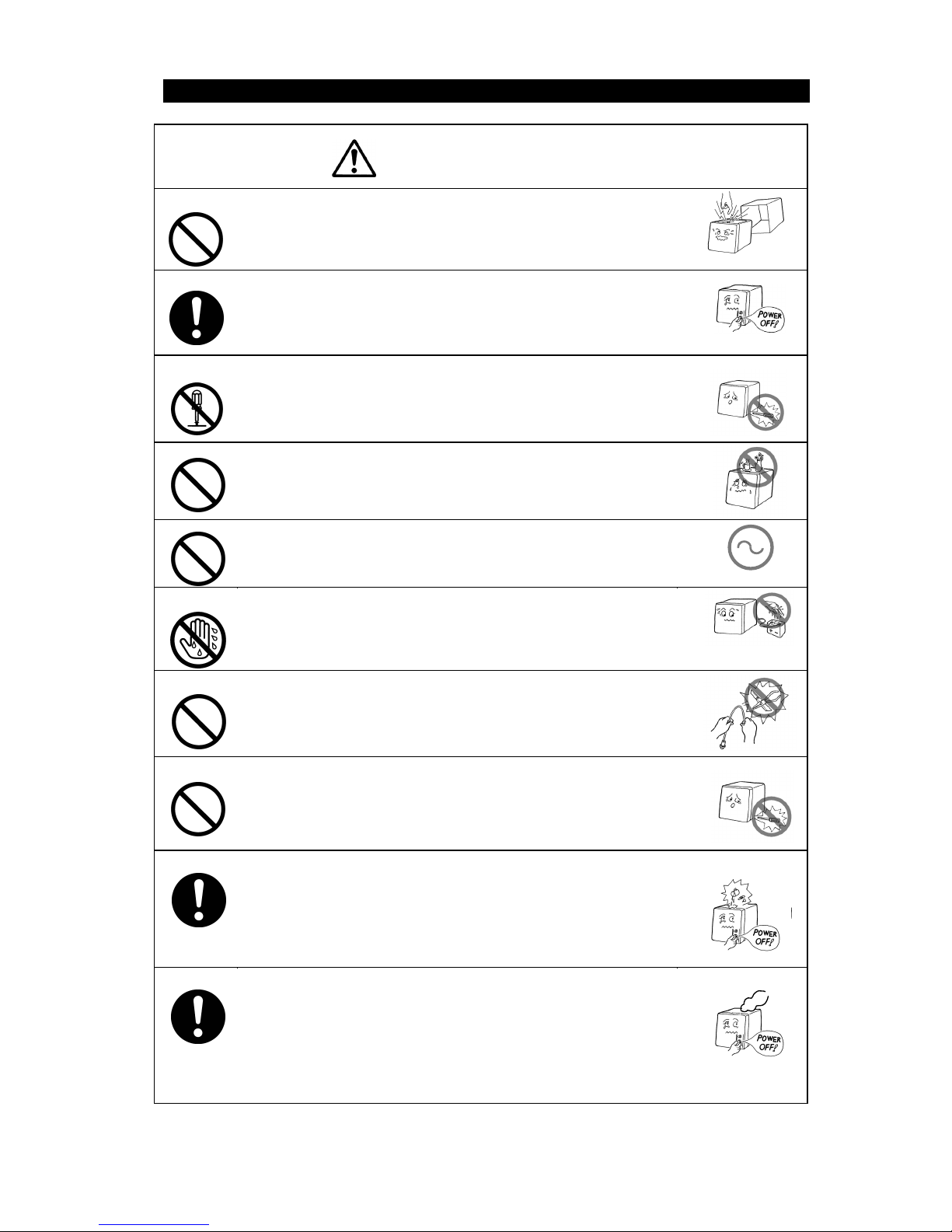
Indicates warning items that, if ignored, may
result in serious personal injury or even death.
Indicates cautionary items that, if ignored, may
result in personal injury or physical damage.
Examples of Related Symbol Marks Used in this Manual and on the Unit
Each mark is intended to alert the user to the presence of
precautions including danger and warning items. The picture in each
mark (“Electric shock” in the example on the left.) alerts you to
operations that should be carefully performed.
Each
mark is intended to alert the user to the presence of prohibited
activity. The picture/word in/beside each mark (“Disassembling
Prohibited” in the example on the left.) alerts you to operations that are
prohibited.
Each
mark is intended to alert the user to the presence of
necessary instructions. The picture in each
mark (“Disconnect the
power plug” in the example on the left.) alerts you to operations that
must be performed.
WARNING LABEL
You can see the warning label on the top of the unit.
Do not attempt to remove the warning label from the unit or impair or modify it.
Page 5
iii
Usage Hints
Do not remove the cover of this unit. Otherwise, you may touch a
high-voltage part and suffer from an electric shock.
Turn off the power on/off switch, and turn off the power supply
breaker when you for maintenance check this unit for
maintenance. Otherwise, a fire, an electric shock, or a failure may
occur.
Do not disassemble or modify this unit. Otherwise, a fire, an
electric shock, or a failure may occur.
Do not place a vessel containing water, etc. or a metallic object on
this unit. When water spills or when water or the object enters the
unit, a fire, an electric shock, or a failure may occur.
Do not use this unit at a voltage other than the supply voltage
stated on the unit. Otherwise, a fire, an electric shock, or a failure
may occur.
Do not insert or remove the power cord or operate switches with a
wet hand. Otherwise, you may suffer from an electric shock.
Do not damage or modify the power cord. Placing a heavy object
onto, heating, stretching or bending the cord may cause a fire or
an electric shock.
Do not check or repair in this unit. Please call our field
representative or your nearest JRC office for inspection and repair
services. Otherwise It may cause a fire or an electric shock.
In the event that you spill or drop any liquids or metals etc., turn off
the unit, turn off the power supply breaker, and contact your sales
agent outlet or one of JRC branch offices, sales centers or liaison
offices. Otherwise continuing operation may cause a fire, an
electric shock or a malfunction.
In the event that smoking or burning odors are detected,
immediately terminate operation of the unit and contact your sales
agent outlet or one of JRC branch offices, sales centers or liaison
offices. Never attempt to check or repair the interior of the unit.
Otherwise continuing operation may cause a fire or an electric
shock.
AC
WARNING
Page 6
iv
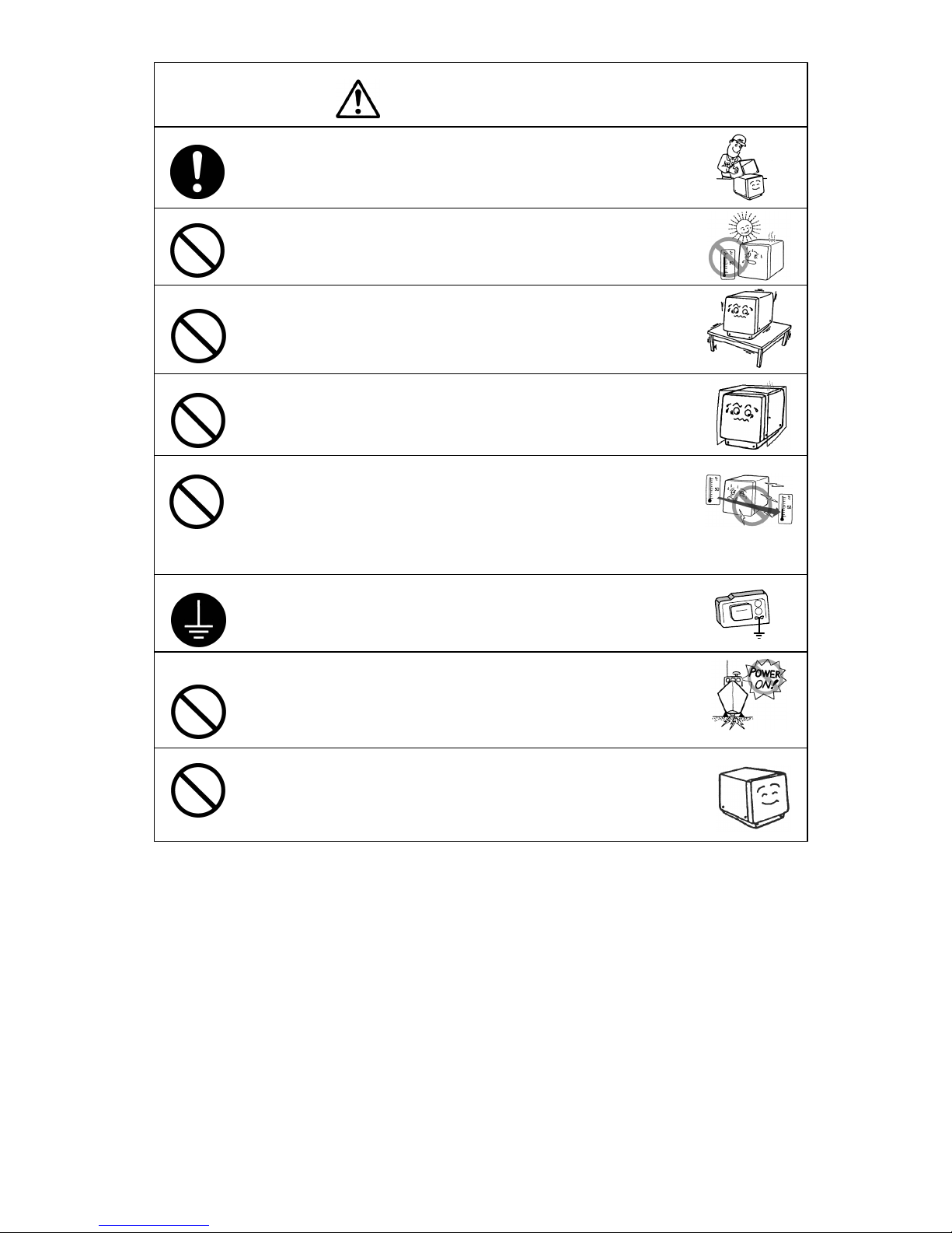
Without qualified service personnel, do not attempt to install this
unit. Contact our service center or agent for any electrical work or
installation of this unit. Otherwise it may cause a malfunction.
Do not install this unit at the place exposed to direct sunlight for a
long time or hit by hot wind or where the temperature rises above
55℃. Otherwise it may cause a fire or a breakdown.
Do not place the unit on a wobbly stand or any unsteady
foundation. Otherwise it may cause the unit to fall, resulting in an
injury or a damage.
Do not put this unit in the cabinet, and do not cover with the
nonporous thing such as cardboard. Heat shuts oneself up, and it
may cause a fire or a breakdown.
When this unit is suddenly moved from a cool place to a warm
place, drew condensation water may form on the inside windows,
and the liquid crystal part can become visually difficult. In this
case, leave the unit for a while until becoming dry condition. Then
operate the unit.
When installing this set, be sure to connect the grounding wire or
the grounding plate to the grounding terminal of the unit.
Otherwise you may suffer from an electric shock.
Do not turn on the power switch of the unit while the ship is on the
shore. Otherwise, the transducer may malfunction.
Do not use an organic solvent such as thinner or benzine when
you clean the surface of the unit. For cleaning the surface, remove
the dust and wipe with clean dry cloth. Otherwise, the painting on
the surface may be damaged
CAUTION
Page 7
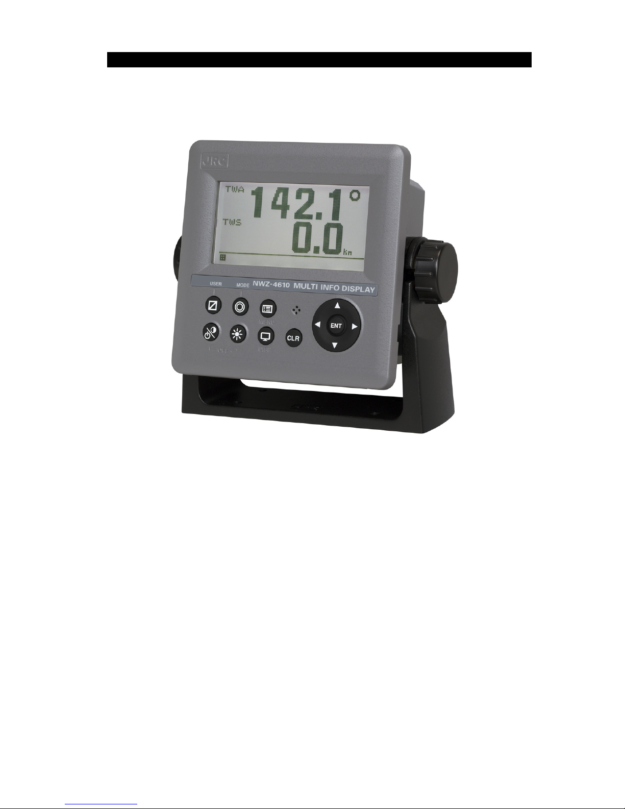
v
External View
Page 8

Contents
General Information ...................................................................................................................... i
Before You Begin .......................................................................................................................... ii
Usage Hints .................................................................................................................................. iii
External View ................................................................................................................................ v
Chapter 1 Introduction .......................................................................................................... 1-1
1.1. Function ............................................................................................................................... 1-1
1.2. Features ............................................................................................................................... 1-2
1.3. Components ......................................................................................................................... 1-3
1.3.1. Standard equipment ....................................................................................................... 1-3
1.3.2. Options........................................................................................................................... 1-3
1.4. Construction ........................................................................................................................ 1-4
1.5. System Configuration ......................................................................................................... 1-5
Chapter 2 Names and Functions of the Components ........................................................ 2-1
Chapter 3 Display Screen ..................................................................................................... 3-1
3.1. Display Screen ..................................................................................................................... 3-1
Chapter 4 Operation .............................................................................................................. 4-1
4.1. Menu ..................................................................................................................................... 4-2
4.2. Basic Operation ................................................................................................................... 4-8
4.2.1. Turning on the power ..................................................................................................... 4-8
4.2.2. Starting (Normal) ............................................................................................................ 4-8
4.2.3. Starting (Abnormal) ........................................................................................................ 4-9
4.2.4. Starting (Abnormal) ........................................................................................................ 4-9
4.2.5. Turning off the power ..................................................................................................... 4-9
4.2.6. Adjusting the back light (lighting) by using the key ...................................................... 4-10
4.2.7. Adjusting contrast ........................................................................................................ 4-10
4.2.8. Turning off the alarm buzzer ........................................................................................ 4-10
4.2.9. Switching display ......................................................................................................... 4-10
4.2.10. Alarm display ............................................................................................................... 4-10
4.2.11. Selecting items from the menus .................................................................................. 4-11
4.2.12. Entering a numeric value ............................................................................................. 4-12
4.3. User Mode Change ............................................................................................................ 4-13
4.4. User Setting Screen Display ............................................................................................ 4-13
4.5. Setting Display .................................................................................................................. 4-14
4.5.1. Adjusting contrast ........................................................................................................ 4-14
4.5.2. Adjusting back light ...................................................................................................... 4-15
4.5.3. Setting a click sound .................................................................................................... 4-15
4.5.4. Setting a display screen............................................................................................... 4-15
4.5.5. Selecting a back light color .......................................................................................... 4-21
4.5.6. Setting graph scale ...................................................................................................... 4-22
4.5.7. Registering user display .............................................................................................. 4-22
4.6. System Settings ................................................................................................................ 4-23
4.6.1. Selecting units ............................................................................................................. 4-23
4.6.2. Setting the time difference ........................................................................................... 4-24
4.6.3. Setting date display format .......................................................................................... 4-25
4.6.4. Displaying as loran c time difference ........................................................................... 4-25
4.6.5. Setting transducer position of depth sounder (exclusive to JFE-380/680) .................. 4-25
4.6.6. Setting water depth offset of depth sounder ................................................................ 4-26
4.7. Language Settings ............................................................................................................ 4-27
4.8. Alarm Settings ................................................................................................................... 4-27
4.8.1. Setting the alarm range ............................................................................................... 4-28
4.8.2. Setting a system alarm ................................................................................................ 4-28
4.8.3. Setting a vessel speed alarm ...................................................................................... 4-29
4.8.4. Setting a TRIP alarm ................................................................................................... 4-29
4.8.5. Setting the water temperature alarm ........................................................................... 4-30
4.8.6. Setting the water depth alarm ...................................................................................... 4-30
4.8.7. Setting the wind velocity alarm .................................................................................... 4-30
4.8.8. Setting the air temperature alarm ................................................................................ 4-31
4.8.9. Setting the atmosphere alarm ..................................................................................... 4-31
4.8.10. Setting the humidity alarm ........................................................................................... 4-31
4.8.11. Setting a buzzer sound and screen back light ............................................................. 4-32
4.9. Setting Installation ............................................................................................................ 4-33
Page 9

4.9.1.
Changing to a maintenance mode ............................................................................... 4-33
4.9.2. Setting a model ............................................................................................................ 4-34
4.9.3. Selecting a dimmer unit ............................................................................................... 4-34
4.9.4. Dimmer linked control and data sharing with RS-485 ................................................. 4-35
4.9.5. Setting a serial port ...................................................................................................... 4-38
4.9.6. Setting a contact port ................................................................................................... 4-42
4.9.7. Outputting alarm history ............................................................................................... 4-43
4.9.8. Checking installation .................................................................................................... 4-43
4.9.9. Checking the input port ................................................................................................ 4-44
4.9.10. Self-diagnosis .............................................................................................................. 4-44
4.9.11. Displaying an alarm ..................................................................................................... 4-45
4.9.12. Displaying the software version ................................................................................... 4-46
4.9.13. Performing master reset .............................................................................................. 4-46
4.9.14. Demonstration ............................................................................................................. 4-47
4.9.15. Outputting setting value ............................................................................................... 4-47
4.9.16. Setting the current to be displayed .............................................................................. 4-47
4.10. Setting daisy chain ........................................................................................................ 4-48
Chapter 5 Maintenance ......................................................................................................... 5-1
5.1. Daily Maintenance ............................................................................................................... 5-2
5.2. Alarm .................................................................................................................................... 5-3
5.3. Troubleshooting for Malfunctions or Abnormalities ....................................................... 5-4
5.4. Repair Unit ........................................................................................................................... 5-5
5.4.1. Repair unit...................................................................................................................... 5-5
5.4.2. Regular Replacement Parts ........................................................................................... 5-5
Chapter 6 Installation ............................................................................................................ 6-1
6.1. Affixing Display Unit Nameplate Labels ........................................................................... 6-2
6.1.1. Affixing product nameplate ............................................................................................ 6-2
6.1.2. Affixing model identification plate .................................................................................. 6-2
6.2. Display Unit Installation ...................................................................................................... 6-3
6.2.1. Selecting the position for installation ............................................................................. 6-3
6.2.2. Mounting the display unit using a rack .......................................................................... 6-4
6.2.3. Mounting using a flash mount ........................................................................................ 6-6
6.2.4. Removing the display unit by flash mounting ................................................................ 6-8
6.3. Cable Connection ................................................................................................................ 6-9
6.3.1. DC12/24V DATA connector ......................................................................................... 6-10
6.3.2. DATA1 connector ......................................................................................................... 6-13
6.3.3. SENSOR/DATA2 connector ......................................................................................... 6-17
6.4. Optional Peripheral Connection ...................................................................................... 6-21
6.4.1. Dimmer unit connection ............................................................................................... 6-21
Chapter 7 After-Sales Service .............................................................................................. 7-1
7.1. When Ordering a Repair ..................................................................................................... 7-1
7.2. Recommendation of Overhaul ........................................................................................... 7-1
Chapter 8 Disposal ................................................................................................................ 8-1
8.1. Disposal of the Equipment ................................................................................................. 8-1
Chapter 9 Specifications ....................................................................................................... 9-1
Appendix ..................................................................................................................... Appendix-1
Appendix 1 Outline and Setting Drawing ................................................................. Appendix-1
Appendix 2 Default value ........................................................................................... Appendix-3
Appendix 3 Setting value memo............................................................................. Appendix-7
Page 10

Page 11

1-1
Chapter 1 Introduction
1.1. Function
The Multi Information Display (MID) is the display unit that receives NMEA data items from various
sensors to display them.
The screen can be split to up to 4 areas for use. Only necessary information can be displayed by
selecting data to be displayed in the areas.
There are three modes in which six screens can be registered, and up to 18 screens can be registered.
Page 12

1-2
1.2. Features
NWZ-4610 Multi Information Display (MID) has the following features:
1) Display of various NMEA data items
2) Selection of display contents and screen layout
3) Distribution of power supply in daisy chain mode
4) Selection of display screen in each mode
5) Sharing of data and interlocking of dimmer between display units at RS-485 interface
Page 13
1-3
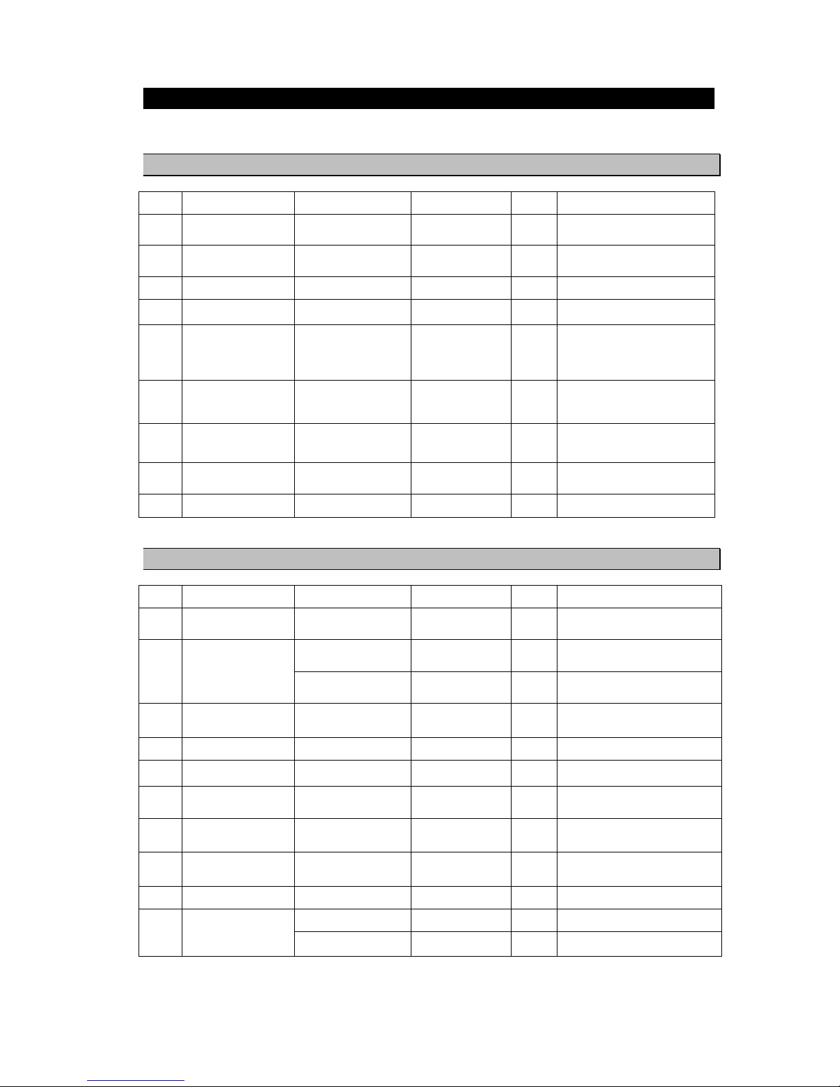
1.3. Components
The standard equipment and options are shown in the tables below.
1.3.1. Standard equipment
No. Description Model No. CODE QTY Remarks
1.1
DISPLAY NWZ-4610 NWZ-4610 1 Main Body
1.2
DATA POWER CABLE CFQ-5766A CFQ5766A 1
14 cores 2 m/ With Fuse holder
data, power, contact
1.3
FUSE MF60NR 250V 1 5ZFGD00205 2 Display unit 1A fuse
1.4
FRONT PANEL MTV305018A MTV305018A 1
1.5
BASE KITS MPBX47065 MPBX47065 1
Base
Knob Bolt
Gear Washer
Knob Washer
1.6
MODEL
IDENTIFICATION
PLATE
MPNN47524A MPNN47524A 1 For Rear
1.7
PRODUCT
NAMEPLATE
MPNN47529A MPNN47529A 1 For Front
1.8
Flush Mounting
Drawing
- - 1 For Flush Mount
2
QUICK REFERENCE 7ZPNA4352 7ZPNA4352 1 English/Japanese
1.3.2. Options
No. Description Model No. CODE QTY Remarks
1
AC POWER
RECTIFIER
NBD-577C NBD-577C 1 AC100/220V input
24V output
2
DATA POWER CABLE CFQ-5766D CFQ5766D 1 14 cores 10 m/ With Fuse holder
data, power, contact
CFQ-5766F CFQ5766F 1 14 cores 20 m/ With Fuse holder
data, power, contact
3
DATA CABLE CFQ-5767 CFQ5767 1 4 cores/3 m data
6-pin connector data line only
4
DATA CABLE CFQ-5768 CFQ5768 1 6 cores-14 cores/3 m daisy chain
5
DATA CABLE CFQ-5769 CFQ5769 1 For RS-485 4 cores/3 m
6
T-SHAPED
CONNECTOR
AA-040404-MMM-TL 5JCDX00071 1 For CFQ-5769 RS-485
7
JUNCTION BOX CQD-10 CQD-10A 1 12 terminals
8
DIMMER UNIT NCM-227 NCM-227 1 External dimmer unit
9
L-TYPE ADAPTER CFQ-9184 CFQ9184 1
10
INSTRUCTION
MANUAL
7ZPNA4284 7ZPNA4284 1 English
7ZPNA4283 7ZPNA4283 1 Japanese
Page 14
1-4
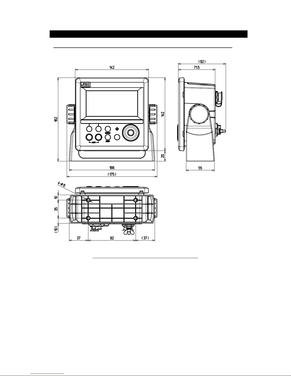
1.4. Construction
Display NWZ-4610
Figure 1.2 NWZ-4610 OUT LINE (Disk Form type)
Unit: mm
Mass: Approximately 0.8kg
Page 15
1-5
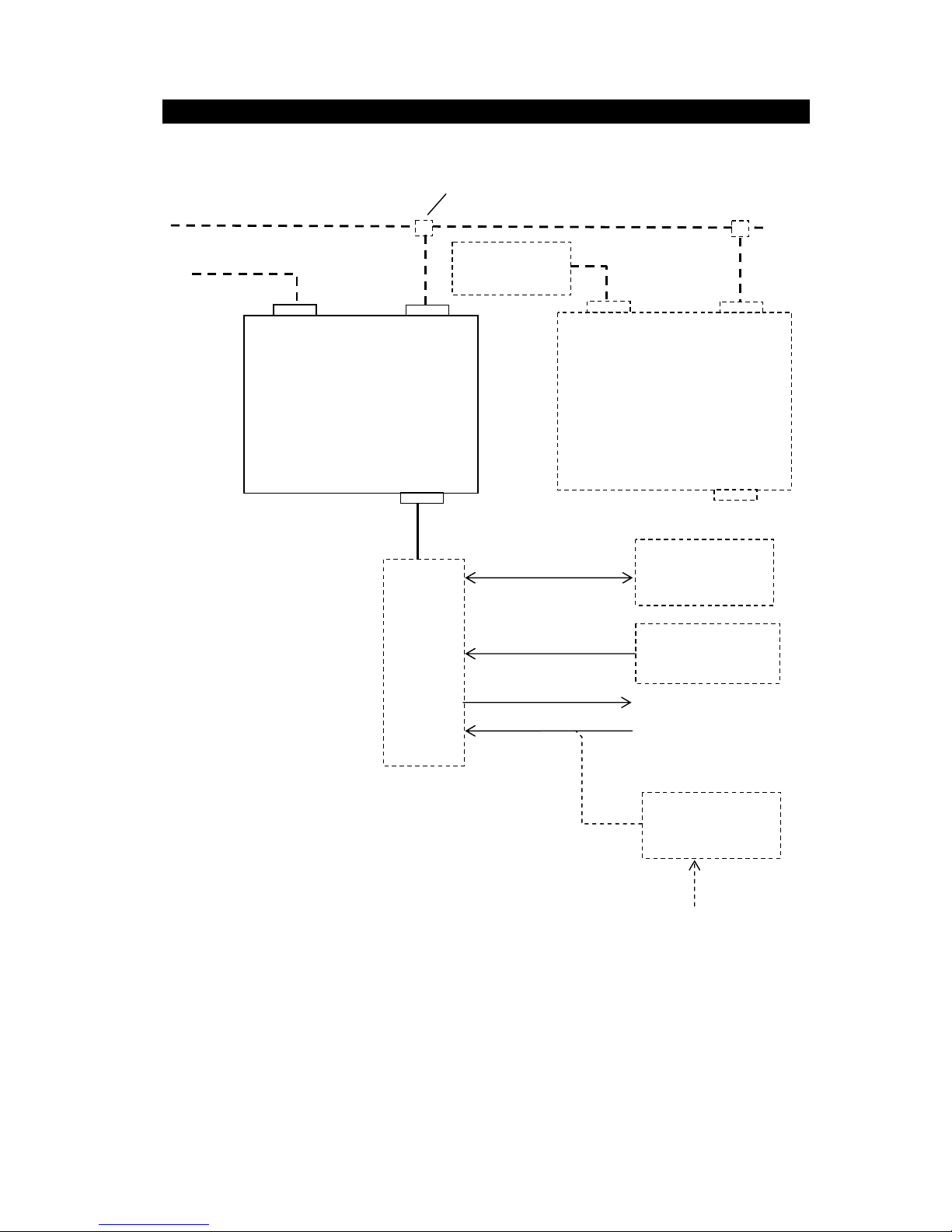
1.5. System Configuration
Junction
box
CQD-10
AC Power
Rectifier
NBD-577C
SENSOR/DATA2 DATA1
MID
NWZ-4610
DC12/24V DATA
Dimmer unit
NCM-227
External device
Sensors
SENSOR/DATA2 DATA1
MID
NWZ-4610
DC12/24V DATA
DC12/24V
100/220V AC
Log pulse
CFQ-5766A
2 m
Daisy chain
CFQ-5768 3m
RS-485
CFQ-5769 3m
RS-485
CFQ-5769 3m
RS-485
CFQ-5769
3m
T-shaped connector
AA-040404-MMM-TL
* 250V-TTYCS-1
3 ports
*250V-TTYCS-1
Max 15 m
*250V-TTYCS-1
*0.6/1kV-DPYC-1.5
*: Arranged by dockyard.
External device
Sensors
CFQ-5767
3m
Page 16

1-6
Page 17
2-1
Chapter 2 Names and Functions of
the Components
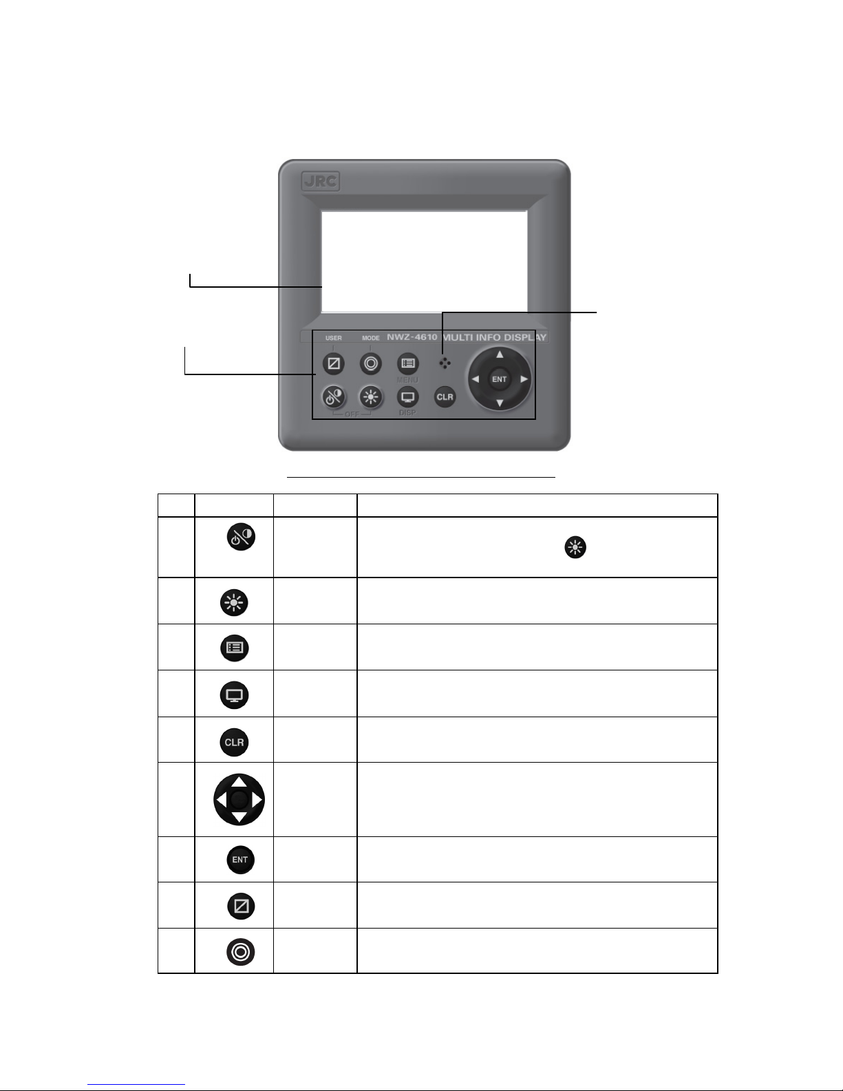
Display
Buzzer
Operation panel
Figure 2.1 Operation panel of main display unit
No. Keys Name Functions
1 Power/
Contrast key
Turns on the power. This key also adjusts the screen contrast.
The power is turned off when the
key and this key are
pressed at the same time.
2
Dimmer key
Adjusts the brightness.
3
Menu key
Displays the main menu.
4 Display key Changes the display screen.
5 Clear key Cancels operation and stops the alarm.
6
Cursor key
Moves the cursor.
7 Enter key Sets the entries.
8 USER key Changes the screen to the user registration screen.
9 MODE key Change the user mode.
Page 18
2-2
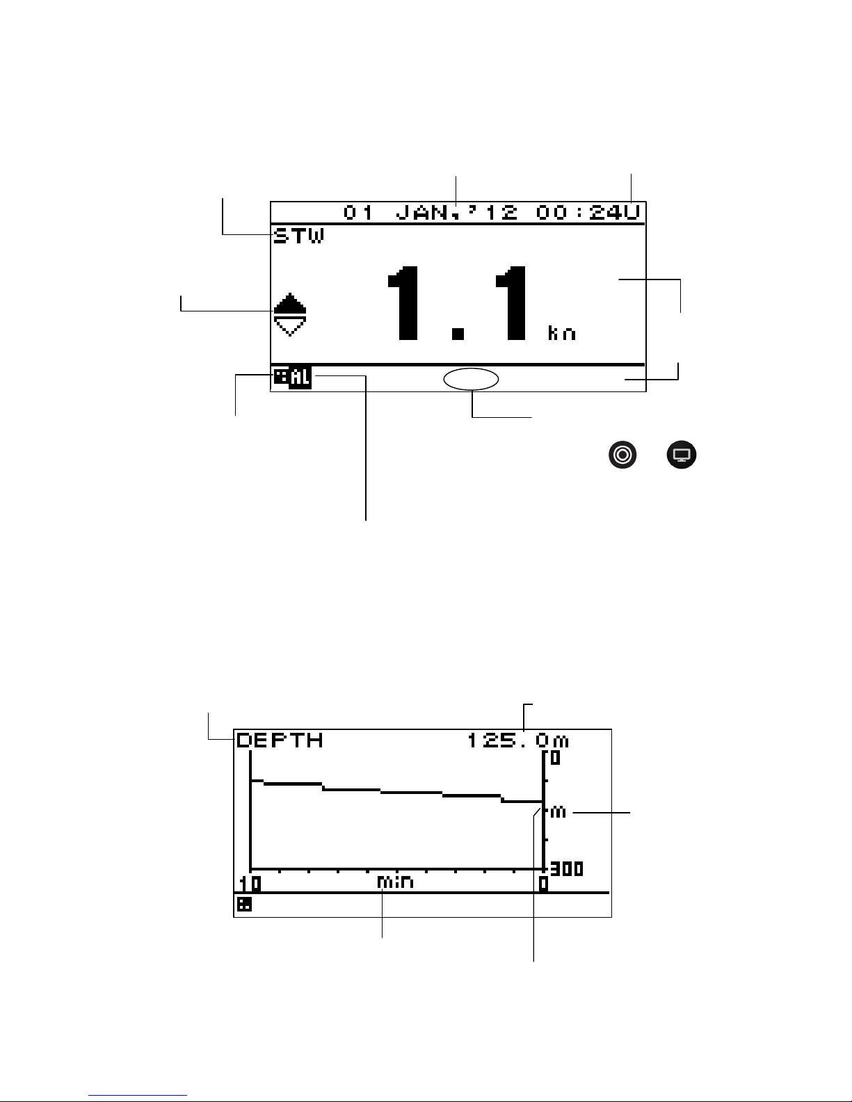
Reading the Display
Numeric display screen
Graphic screen
Graph screen
Screen title
Screen number
The display mode and the screen number
are displayed. When
or is
pressed, M1 to M3: Mode and D1 to D6:
Screen number are displayed for 3
seconds.
[S]: Simulation mode
During simulation mode, [S] blinks.
[M]: Equipment mode
During equipment mode, [M] is turned on.
During simulation mode, [M] is turned off.
Alarm icon
This displayed while an alarm occurs. For the
alarm contents, check the alarm information.
Display area
Freeze indicator
During operation, the black part moves.
If the black part does not move, the
screen freezes.
Ship speed and
direction
U: UTC
L: Local time
Date and time
If date and time data is not received, "-" is displayed.
Graph title
Current measured value
Horizontal axis: Elapsed time [minute]
More left data is older.
Vertical axis
measured
value
Current
measured
value
Status bar
Page 19
2-3
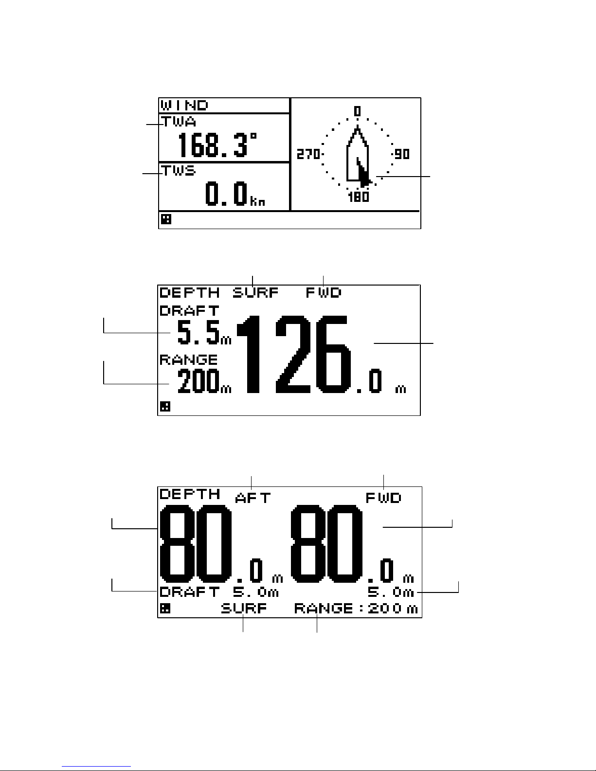
Wind direction/wind velocity screen
The left and right keys can be used to switch between true and relative.
Special screen for JFE-380/680
1) Single Transducer
Display mode Position of Transducer
Offset
Depth
Range
2) Dual Transducer
Position of Transducer1 Position of Transducer2
Depth of Depth of
Transducer1 Transducer2
Offset of Offset of
Transducer1 Transducer2
Display mode Range
True win d
direction
True win d
velocity
Wind direction
Arrow from
windward
Page 20
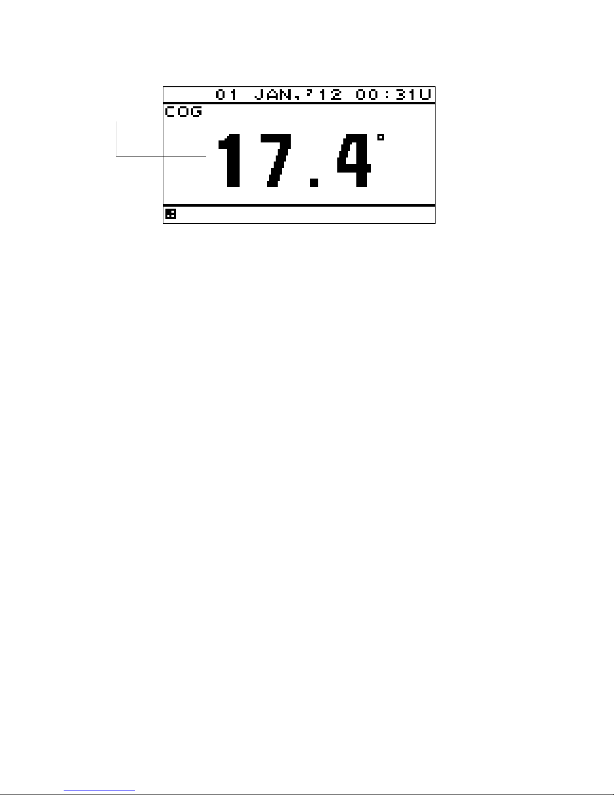
2-4
COG screen
When the COG is invalid, "---.-" is displayed.
COG
Page 21
3-1
Chapter 3 Display Screen
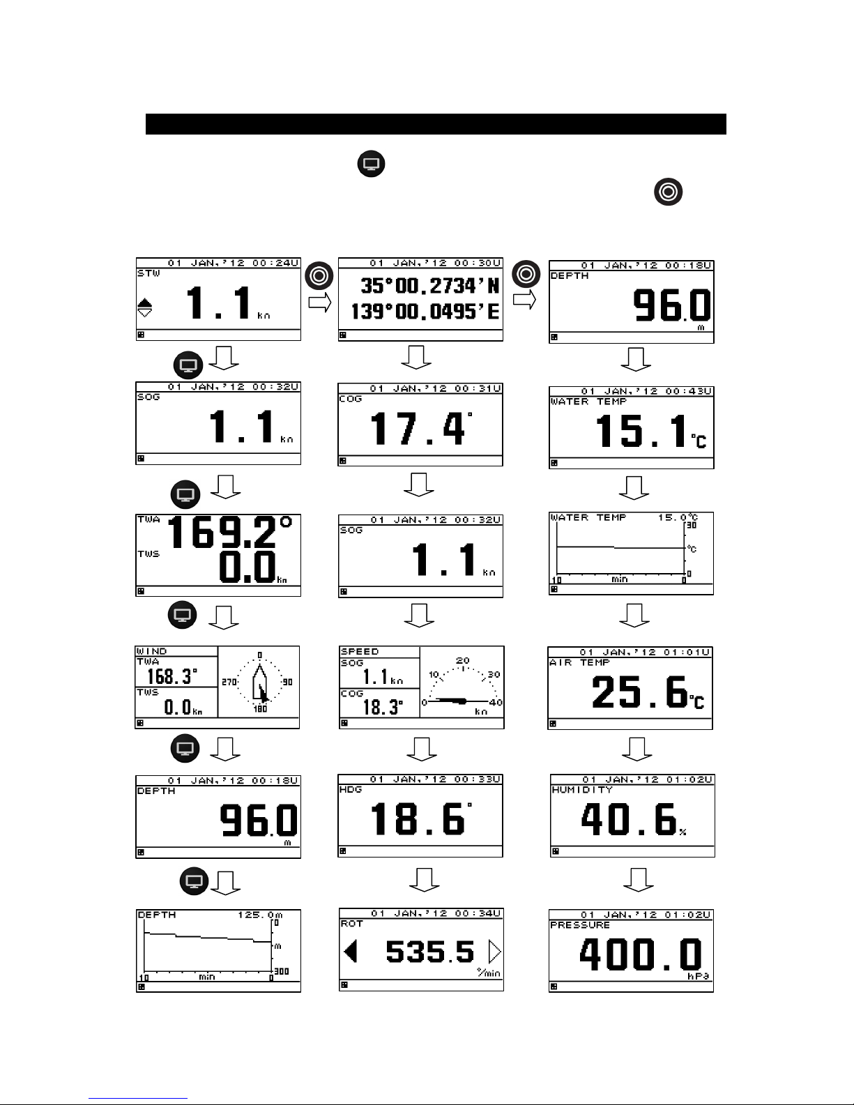
3.1. Display Screen
The screen is switched each time the
key is pressed. Up to six screens can be displayed. The
screen after the power is turned on becomes the screen when it is turned off. When the
key is
pressed, the mode is switched. The following screens are factory-set.
Mode 1 Mode 2 Mode 3
Page 22
3-2
Split screen display
The screen can be split into 1 to 4 areas to display multiple information items.
1-split screen 2-split screen
3-split screen 4-split screen
Enlarged part display
Integer part or decimal can be highlighted.
Enlarged integer part screen Enlarged decimal part screen
Page 23
4-1
Chapter 4 Operation
Do not place a vessel containing water, etc. or a metallic object on this unit.
When water spills or when water or the object enters the unit, a fire, an electric
shock, or a failure may occur.
Do not use this unit at a voltage other than the supply voltage stated on the unit.
Otherwise, a fire, an electric shock, or a failure may occur.
Do not insert or remove the power cord or operate switches with a wet hand.
Otherwise, you may suffer from an electric shock.
Do not damage or modify the power cord. Placing a heavy object onto, heating,
stretching or bending the cord may cause a fire or an electric shock.
When this unit is suddenly moved from a cool place to a warm place, drew
condensation water may form on the inside windows, and the liquid crystal part
can become visually difficult. In this case, leave the unit for a while until
becoming dry condition. Then operate the unit.
WARNING
CAUTION
Page 24
4-2
4.1. Menu
Normal menu
Main menu Sub menu Range remarks
DISPLAY LCD 4.5
CONTRAST 1-13 4.5.1
DIMMER MAXIMUM 4-13 4.5.2
DIMMER TYPICAL 3-12 4.5.2
DIMMER MINMUM 2-11 4.5.2
CLICK SOUND ON/OFF 4.5.3
MODE1 4.5.4.1
DISPLAY1 4.5.4.2
SEGMENTATION1 4.5.4.3
DISPLAY 4.5.4.4
OWN SHIP
LAT/LON/HDG/ROT/COG/
SOG/PITCH/ROLL/HEAVING/
4.5.4.4
WEATHER
WATER TEMP/TWA/TWS/AWS/
AIRTEMP/PRESSURE/HUMIDITY
4.5.4.4
DOPPLER
TRIP/ODO/DEPTH/STW/
BOW STW/
STERN STW/SOG(LOG)/
BOW SOG(LOG)/
STERN SOG(LOG)/
CORRENT L1 SPD/
CORRENT L1 DIR/
CORRENT L2 SPD/
CORRENT L2 DIR/
CORRENT L3 SPD/
CORRENT L3 DIR/
4.5.4.4
ENGINE RUDDER/ENGINE/SHAFT 4.5.4.4
OFF 4.5.4.4
DISPLAY MODE
NORMAL/SPECIAL1/SPECIAL2/AUTO
RANGE
4.5.4.4
AUTO SCREEN ON/OFF 4.5.4.4
SOUND SOUND1/SOUND2/OFF 4.5.4.4
TIME 1-10sec 4.5.4.4
SEGMENTATION2 4.5.4.3
DISPLAY1/2 Same as DISPLAY1/1 4.5.4.4
DISPLAY2/2 Same as DISPLAY1/1 4.5.4.4
AUTO SCREEN ON/OFF 4.5.4.4
SOUND SOUND1/SOUND2/OFF 4.5.4.4
TIME 1-10sec 4.5.4.4
SEGMENTATION3 4.5.4.3
DISPLAY1/3 Same as DISPLAY1/1 4.5.4.4
DISPLAY2/3 Same as DISPLAY1/1 4.5.4.4
DISPLAY3/3 Same as DISPLAY1/1 4.5.4.4
AUTO SCREEN ON/OFF 4.5.4.4
SOUND SOUND1/SOUND2/OFF 4.5.4.4
TIME 1-10sec 4.5.4.4
SEGMENTATION4 4.5.4.3
DISPLAY1/4 Same as DISPLAY1/1 4.5.4.4
DISPLAY2/4 Same as DISPLAY1/1 4.5.4.4
DISPLAY3/4 Same as DISPLAY1/1 4.5.4.4
DISPLAY4/4 Same as DISPLAY1/1 4.5.4.4
AUTO SCREEN ON/OFF 4.5.4.4
SOUND SOUND1/SOUND2/OFF 4.5.4.4
TIME 1-10sec 4.5.4.4
SPECIAL 4.5.4.3
DISPLAY
SINGLE DEPTH/DUAL DEPTH/
WIND
4.5.4.4
Page 25

4-3
Main menu Sub menu Range remarks
AUTO SCREEN ON/OFF 4.5.4.4
SOUND SOUND1/SOUND2/OFF 4.5.4.4
TIME 1-10sec 4.5.4.4
GRAPHIC 4.5.4.3
DISPLAY
WIND/ DEPTH/WATER TEMP/
SPEED1/SPEED2/RUDDER
4.5.4.4
AUTO SCREEN ON/OFF 4.5.4.4
SOUND SOUND1/SOUND2/OFF 4.5.4.4
TIME 1-10sec 4.5.4.4
OFF 4.5.4.3
DISPLAY2 Same as DISPLAY1 4.5.4.2
DISPLAY3 Same as DISPLAY1 4.5.4.2
DISPLAY4 Same as DISPLAY1 4.5.4.2
DISPLAY5 Same as DISPLAY1 4.5.4.2
DISPLAY6 Same as DISPLAY1 4.5.4.2
MODE2 Same as MODE1 4.5.4.1
MODE3 Same as MODE1 4.5.4.1
BACK LIGHT WHITE/ORANGE 4.5.5
GRAPH SCALE 4.5.6
DEPTH 4.5.6
TIME 5min/10min/20min/30min 4.5.6
MAX 1-3048m 4.5.6
MIN 0-3047m 4.5.6
WATER TEMP 4.5.6
TIME 5min/10min/20min/30min 4.5.6
MAX
-36-+37C
4.5.6
MIN
-37-+36C
4.5.6
USER DISPLAY
DISPLAY1/DISPLAY2/DISPLAY3/
DISPLAY4/DISPLAY5/DISPLAY6/OFF
4.5.7
SYSTEM UNIT 4.6.1
DIST/SPD NM,kn/km,km/h/mi,mi/h/m,m/s 4.6.1
TEMP
C/F
/
4.6.1
DEPTH m/ft/fm 4.6.1
WIND kn/km/h/mi/h/m/s 4.6.1
TIME DIFF -13:30 - +13:30 4.6.2
DATE DISP 4.6.3
TIME DISP
DD MMM,’YY HH:MM /
MMM DD,’YY HH:MM /
YY-MMM-DD HH:MM
4.6.3
LORAN C 4.6.4
LORAN C ON/OFF 4.6.4
GRI 4.6.4
TD1 0-99 4.6.4
TD2 0-99 4.6.4
TD1 CORR -9.9 - +9.9 4.6.4
TD2 CORR -9.9 - +9.9 4.6.4
DEPTH 4.6.5/4.6.6
TRANS FWD/MID/AFT 4.6.5
OFFSET -99.9 - +99.9 4.6.6
LANG. LANG.
English/Japan/France/Germany/Italy/
Norway/Spain/Vietnam/Indonesia
4.7
Other than English /
Japanese, it is due to add
one by one.
ALARM SYSTEM ON/OFF 4.8/4.8.1/4.8.2
SOUND ON/OFF 4.8.11
LCD COLOR ON/OFF 4.8.11
SPEED
OVER/UNDER/IN RANG/OUT
RANG/OFF
4.8.3
OVER 4.8.3
OVER 0-99.9kn 4.8.3
SOUND ON/OFF 4.8.11
Page 26

4-4
Main menu Sub menu Range remarks
LCD COLOR ON/OFF 4.8.11
UNDER 4.8.3
UNDER 0-99.9kn 4.8.3
SOUND ON/OFF 4.8.11
LCD COLOR ON/OFF 4.8.11
IN RANGE 4.8.3
MAXIMAUM 0-99.9kn 4.8.3
MINIMUM 0-99.9kn 4.8.3
SOUND ON/OFF 4.8.11
LCD COLOR ON/OFF 4.8.11
OUT RANGE 4.8.3
MAXIMAUM 0-99.9kn 4.8.3
MINIMUM 0-99.9kn 4.8.3
SOUND ON/OFF 4.8.11
LCD COLOR ON/OFF 4.8.11
TRIP OVER/OFF 4.8.4
OVER 4.8.4
OVER 0-99.9kn 4.8.4
SOUND ON/OFF 4.8.11
LCD COLOR ON/OFF 4.8.11
WATER TEMP
OVER/UNDER/IN RANG/OUT
RANG/OFF
4.8.5
OVER 4.8.5
OVER
-99.9 - +99.9C
4.8.5
SOUND ON/OFF 4.8.11
LCD COLOR ON/OFF 4.8.11
UNDER 4.8.5
UNDER
-99.9 - +99.9C
4.8.5
SOUND ON/OFF 4.8.11
LCD COLOR ON/OFF 4.8.11
IN RANGE 4.8.5
MAXIMAUM
-99.9 - +99.9C
4.8.5
MINIMUM
-99.9 - +99.9C
4.8.5
SOUND ON/OFF 4.8.11
LCD COLOR ON/OFF 4.8.11
OUT RANGE 4.8.5
MAXIMAUM
-99.9 - +99.9C
4.8.5
MINIMUM
-99.9 - +99.9C
4.8.5
SOUND ON/OFF 4.8.11
LCD COLOR ON/OFF 4.8.11
DEPTH
OVER/UNDER/IN RANG/OUT
RANG/OFF
4.8.6
OVER 4.8.6
OVER 0 – 999.9m 4.8.6
SOUND ON/OFF 4.8.11
LCD COLOR ON/OFF 4.8.11
UNDER 4.8.6
UNDER 0 – 999.9m 4.8.6
SOUND ON/OFF 4.8.11
LCD COLOR ON/OFF 4.8.11
IN RANGE 4.8.6
MAXIMAUM 0 – 999.9m 4.8.6
MINIMUM 0 – 999.9m 4.8.6
SOUND ON/OFF 4.8.11
LCD COLOR ON/OFF 4.8.11
OUT RANGE 4.8.6
MAXIMAUM 0 – 999.9m 4.8.6
MINIMUM 0 – 999.9m 4.8.6
Page 27

4-5
Main menu Sub menu Range remarks
SOUND ON/OFF 4.8.11
LCD COLOR ON/OFF 4.8.11
WIND OVER/OFF 4.8.7
OVER 4.8.7
OVER 99.9kn 4.8.7
SOUND ON/OFF 4.8.11
LCD COLOR ON/OFF 4.8.11
AIR TEMP
OVER/UNDER/IN RANG/OUT
RANG/OFF
4.8.8
OVER 4.8.8
OVER
-99.9 - +99.9C
4.8.8
SOUND ON/OFF 4.8.11
LCD COLOR ON/OFF 4.8.11
UNDER 4.8.8
UNDER 0 – 999.9m 4.8.8
SOUND ON/OFF 4.8.11
LCD COLOR ON/OFF 4.8.11
IN RANGE 4.8.8
MAXIMAUM
-99.9 – +99.9C
4.8.8
MINIMUM
-99.9 – +99.9C
4.8.8
SOUND ON/OFF 4.8.11
LCD COLOR ON/OFF 4.8.11
OUT RANGE 4.8.8
MAXIMAUM
-99.9 – +99.9C
4.8.8
MINIMUM
-99.9 – +99.9C
4.8.8
SOUND ON/OFF 4.8.11
LCD COLOR ON/OFF 4.8.11
PRESSURE
OVER/UNDER/IN RANG/OUT
RANG/OFF
4.8.9
OVER 4.8.9
OVER 0 – 9999.9 hPa 4.8.9
SOUND ON/OFF 4.8.11
LCD COLOR ON/OFF 4.8.11
UNDER 4.8.9
UNDER 0 – 9999.9 hPa 4.8.9
SOUND ON/OFF 4.8.11
LCD COLOR ON/OFF 4.8.11
IN RANGE 4.8.9
MAXIMAUM 0 – 9999.9 hPa 4.8.9
MINIMUM 0 – 9999.9 hPa 4.8.9
SOUND ON/OFF 4.8.11
LCD COLOR ON/OFF 4.8.11
OUT RANGE 4.8.9
MAXIMAUM 0 – 9999.9 hPa 4.8.9
MINIMUM 0 – 9999.9 hPa 4.8.9
SOUND ON/OFF 4.8.11
LCD COLOR ON/OFF 4.8.11
HUMIDITY
OVER/UNDER/IN RANG/OUT
RANG/OFF
4.8.10
OVER 4.8.10
OVER 0 – 99.9 % 4.8.10
SOUND ON/OFF 4.8.11
LCD COLOR ON/OFF 4.8.11
UNDER 4.8.10
UNDER 0 – 99.9 % 4.8.10
SOUND ON/OFF 4.8.11
LCD COLOR ON/OFF 4.8.11
IN RANGE 4.8.10
Page 28

4-6
Main menu Sub menu Range remarks
MAXIMAUM 0 – 99.9 % 4.8.10
MINIMUM 0 – 99.9 % 4.8.10
SOUND ON/OFF 4.8.11
LCD COLOR ON/OFF 4.8.11
OUT RANGE 4.8.10
MAXIMAUM 0 – 99.9 % 4.8.10
MINIMUM 0 – 99.9 % 4.8.10
SOUND ON/OFF 4.8.11
LCD COLOR ON/OFF 4.8.11
Maintenance menu
Main menu Sub menu Range Reference/remarks
DAISY CHAIN ON/OFF 4.10
INTERFACE DATA I/O 4.9.5
DATA IN/OUT1 4.9.5
NMEA 4.9.5
DATA IN/OUT SEND/RECEIVE 4.9.5
VERSION 1.5/2.1/2.3/4.0 4.9.5 SEND only
SENTENCE Sentence list 4.9.5 SEND only
BIT RATE 4800/9600/19200/38400 4.9.5
IEC 4.9.5
DATA IN/OUT SEND/RECEIVE 4.9.5
SENTENCE Sentence list 4.9.5 SEND only
BIT RATE 4800/9600/19200/38400 4.9.5
DATA IN/OUT2 4.9.5
NMEA 4.9.5
DATA IN/OUT SEND/RECEIVE 4.9.5
VERSION 1.5/2.1/2.3/4.0 4.9.5 SEND only
SENTENCE Sentence list 4.9.5 SEND only
BIT RATE 4800/9600/19200/38400 4.9.5
IEC 4.9.5
DATA IN/OUT SEND/RECEIVE 4.9.5
SENTENCE Sentence list 4.9.5 SEND only
BIT RATE 4800/9600/19200/38400 4.9.5
DATA IN/OUT3 4.9.5
NMEA 4.9.5
DATA IN/OUT SEND/RECEIVE 4.9.5
VERSION 1.5/2.1/2.3/4.0 4.9.5 SEND only
SENTENCE Sentence list 4.9.5 SEND only
BIT RATE 4800/9600/19200/38400 4.9.5
IEC 4.9.5
DATA IN/OUT SEND/RECEIVE 4.9.5
SENTENCE Sentence list 4.9.5 SEND only
BIT RATE 4800/9600/19200/38400 4.9.5
DATA IN/OUT4 4.9.5
NMEA 4.9.5
VERSION 1.5/2.1/2.3/4.0 4.9.5 SEND only
SENTENCE Sentence list 4.9.5 SEND only
BIT RATE 4800/9600/19200/38400 4.9.5
IEC 4.9.5
SENTENCE Sentence list 4.9.5 SEND only
BIT RATE 4800/9600/19200/38400 4.9.5
RS-485 4.9.4.4
NMEA 4.9.4.4
VERSION 1.5/2.1/2.3/4.0 4.9.4.4 SEND only
SENTENCE Sentence list 4.9.4.4 SEND only
BIT RATE 38400/57600/76800/115200 4.9.4.4
Page 29

4-7
Main menu Sub menu Range Reference/remarks
IEC 4.9.4.4
SENTENCE Sentence list 4.9.4.4 SEND only
BIT RATE 38400/57600/76800/115200 4.9.4.4
CONTACT INPUT DIMMER/ACK 4.9.6.1
CONTACT OUTPUT
200PULSE/NM/
400PULSE/NM/
OFF
4.9.6.2
DIAGNOSIS CONFIG OUT/ERROR LOG OUT 4.9.7/4.9.15
MAINTENANCE INPUT DATA 4.9.9
DIAGNOSIS 4.9.10
DISPLAY DIAG 4.9.10
MONITOR TEST 4.9.10
BUZZER TEST 4.9.10
ERROR LOG 4.9.11
ALARM 4.9.11
ERROR LOG 4.9.11
SOFT VERSION 4.9.12
DISPLAY VER 4.9.12
APP VER 4.9.12
SERIAL NUMBER 4.9.12
BARCODE 4.9.12
MASTER
RESET
GRAPH RESET 4.9.13
DISPLAY RESET 4.9.13
DEMO MODE DEMO TYPE 4.9.14
STATIC 4.9.14
COURSE 0-359.9° 4.9.14
STRAIGHT 4.9.14
SPEED 0-99.9kn 4.9.14
COURSE 0-359.9° 4.9.14
RIGHT 4.9.14
SPEED 0-99.9kn 4.9.14
COURSE 0-359.9° 4.9.14
LEFT 4.9.14
SPEED 0-99.9kn 4.9.14
COURSE 0-359.9° 4.9.14
DATE 4.9.14
TIME 4.9.14
LATITUDE 4.9.14
LONGITUDE 4.9.14
DEMO MODE START/END 4.9.14
SOFT UPDATE DISPLAY -
DESPLAY TYPE MID/LOG/GPS/OFF
4.9.2
Factory setting: OFF
"GPS" is due to add one
by one.
RS-485ID 1-10 4.9.4
DIMMER
GROUP
1-10 4.9.4.3
DIMMER KEY/EXT DIMMER 4.9.3
CURRENT LAYER/DATA No 4.9.16
Page 30
4-8
4.2. Basic Operation
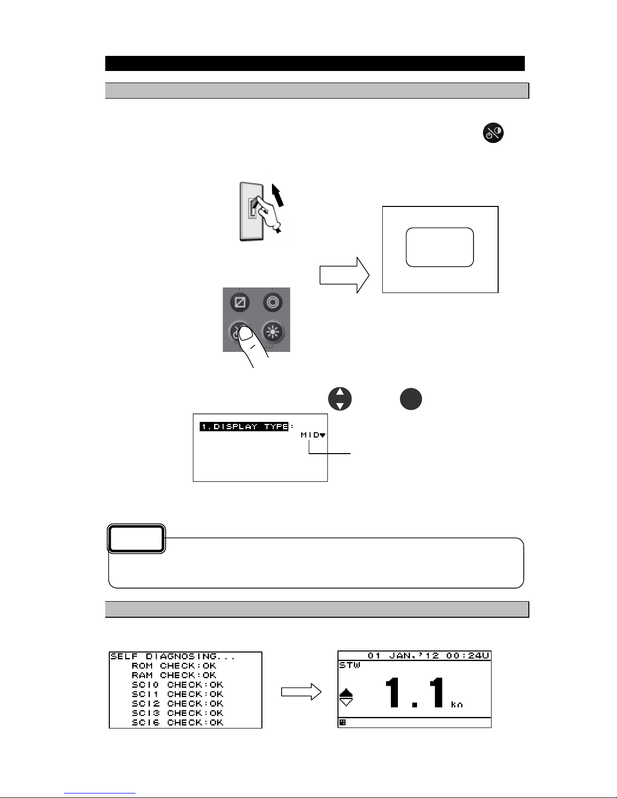
4.2.1. Turning on the power
When the main power is turned on, the power to the display unit is automatically turned on.
In the state in which the power is turned off by the display unit key operation, pressing the
key
turns on the power.
When the main power is OFF
Turning on the main power
When the main power is ON
Turning on the power
Pressing the power key
When the power is ON for first time.
The following screen is displayed. Select a Model with and press .
Model
When "LOG" is selected wrong
Refer to "Caution" in "4.9.2 setting a model".
4.2.2. Starting (Normal)
If all the self-check results are ‘OK’, the screen is automatically changed to the normal screen.
All OK
If the power cannot be turned on, check the main power of the power distribution board and the
cable connection to the display unit.
Caution
JRC
ENT
ON
Page 31

4-9
4.2.3. Starting (Abnormal)
If the self-diagnosis results are errors “NG,” the results are displayed as follows.
4.2.4. Starting (Abnormal)
When the program is corrupted, the following screen is displayed. Turn off the power and contact JRC
or one of our agents.
4.2.5. Turning off the power
If the
key and the key are pressed and held down simultaneously, the power will be
turned off and the screen display will turn off.
When any abnormality (NG) is found, contact JRC or one of our agents.
Caution
R0004
Recovery
mode.
The power may be turned on due to the release timing of your finger.
In this case, first release the and then release the .
Supplement
Page 32

4-10
4.2.6. Adjusting the back light (lighting) by using the key
The brightness of display and operation panel backlight can be set to one of four levels (bright, medium,
dark, off).
Whenever
is pressed, the level changes in the order of bright – medium – dark – off –dark –
medium – bright.
4.2.7. Adjusting contrast
Contrast can be adjusted over 13 levels.
Whenever
is pressed, the contrast is reduced (or increased) from the current setting and after
the contrast reaches the lowest (or highest) level, the contrast increases (reduces) gradually.
4.2.8. Turning off the alarm buzzer
Buzzer sound can be turned off by pressing
.
The buzzer sounds if an alarm occurs.
4.2.9. Switching display
The display screen is switched whenever
is pressed.
4.2.10. Alarm display
When an alarm occurs, the event is notified with a popup menu and alarm sound.
When
is pressed, the popup menu is cleared and the buzzer sound stops. However, display of
“
” remains on the status bar unless the alarm is cancelled.
Even after the popup menu is cleared and the buzzer sound is stopped, the invalid numerical number
keeps blinking until the alarm is cancelled.
To check the alarm again after clearing the popup menu, display the alarm history by referencing
“4.9.11 Displaying an alarm”
The brightness levels other than “off” can be set. See “4.5.2 Adjusting back light”.
An external dimmer unit can also be used for adjusting brightness. See “4.9.3 Selecting a
dimmer unit”.
Supplement
Page 33

4-11
4.2.11. Selecting items from the menus
This section shows the procedure for selecting items from the menus and determining the selection.
Procedure
1. Move the cursor to a required item by using
and press . The item is selected and a
submenu is opened to enable selection of details.
Menu
Submenu
2. Move the cursor to a required item by using
and press . The cursor moves to the
setting value selection.
3. Select a setting value with
and press or . The setting value is confirmed.
4. To return to the previous item, press
or .
The selected
item is displayed
in reverse video.
Setting value
selection
Power must not be off for 10 seconds after setting. When not doing so, the setting value may not
be saved.
Supplement
Page 34

4-12
4.2.12. Entering a numeric value
This section describes the procedure for entering a numeric value.
Procedure
1. Move the cursor to the field in which a value is to be entered by using
.
2. Set a numeric value to be entered by using
and press or .
3. Move the cursor to the right most field and press
or . The setting value is confirmed.
Select a field by using
Select a numeric value by using
If the numeric value that can be entered is restricted by an input range, enter the digits from the
highest order.
To prevent the value from exceeding the input range, the input of the low-order digits is restricted
by the value of the high-order digit.
Example) The input range is from 1 to 10:
If 1 is input in the high-order digit, only 0 can be set as the low order digit.
Power must not be off for 10 seconds after setting. When not doing so, the setting value may not
be saved.
Supplement
Page 35

4-13
4.3. User Mode Change
The user mode can be changed.
Up to three user modes are available, and six screens can be registered in one mode.
For details about how to register the screens in each mode, refer to “4.5.4 Setting a display screen”.
Procedure
1. Press the
key.
Each time the key is pressed, mode 1 changes to mode 2 and to mode 3.
4.4. User Setting Screen Display
From among the screens registered in the display screen, the user-set screen can be displayed.
The user-set screen can also be displayed quickly from other screen by registering the most often-used
screen.
The user-set screen cannot be registered in each use mode.
For details about how to set user screen, refer to “4.5.7 Registering user display”.
Procedure
1. Press the
key.
To return to the original screen, press the
key.
Page 36

4-14
4.5. Setting Display
When “Display” is selected on the main menu, a display menu is displayed.
On the display menu, LCD (contrast and back light), click sound, screen selection, and back light color
can be set.
Each submenu is outlined below.
1) LCD: Adjusts the contrast and sets the back light level.
2) CLICK SOUND: Turns on/off the click sound.
3) MODE 1: You can select MODE 1 screen.
4) MODE 2: You can select MODE 2 screen.
5) MODE 3: You can select MODE 3 screen.
6) BACK LIGHT: You can select the brightness color (white/orange).
7) GRAPH SCALE: You can set the depth and temperature graph scale.
8) USER DISPLAY : You can select the user-set screen.
4.5.1. Adjusting contrast
Adjust the LCD contrast.
The darkest contrast is 1 and the lightest contrast is 13.
The default setting is 7.
Procedure
1. Display a main menu by pressing
.
2. Select “DISPLAY”, “LCD”, and “CONTRAST” in this order by using
.
3. Enter a contrast value by using
and press .
Continued
Page 37

4-15
4.5.2. Adjusting back light
Brightness can be changed by using
. Four levels of brightness are available, bright, medium,
dark, and off.
This section shows how to set a level value of each brightness.
Procedure
1. Display a main menu by pressing
.
2. Select “DISPLAY”, “LCD”, and “DIMMER MAXIMUM/TYPICAL/MINIMUM” in this order by using
.
3. Select a brightness value by using
and press .
4.5.3. Setting a click sound
Turn on/off a key-operation click sound.
ON: Enables a click sound. When the key is pressed, a click sound is emitted.
OFF: Disables a click sound.
Procedure
1. Display a main menu by pressing
.
2. Select “DISPLAY” and “CLICK SOUND” in that order by using
.
3. Select “ON” or “OFF” by using
and press .
4.5.4. Setting a display screen
Up to six display screens can be registered in this display unit.
The display screen can be switched either manually by using
or automatically (auto screen
function).
The auto screen function enables the setting of a switching interval. Switching can also be notified by
emitting a buzzer sound.
Only the integer section or the decimal section of a indication character can be expanded and displayed.
(Display mode)
The setting of the auto screen function and the display mode are performed by "STEP3."
The screen structures of each display screen include customized screens that can be set freely, special
screens that do not allow any setting, and graphic screens. The contents to be displayed on the
display screen can be selected.
The screen selection procedure is as follows.
STEP1 Select the display screen from user mode.
STEP2 Select a screen structure.
STEP3 Select the display contents.
Enter the highest value in “MAXIMUM” and the lowest value in “MINIMUM”.
Supplement
Page 38

4-16
4.5.4.1. Selecting User Mode
MID can set up to three user modes.
Up to six screens can be registered in each mode, and up to 18 screens can be registered.
Press the
key to change the set user mode.
User mode 1 User mode 2 User mode 3
Select the user mode before selecting the display screen.
Procedure
1. Display a main menu by pressing
(normal mode).
2. Press the
key to select “DISPLAY,” and press the key.
3. Press the
key to select “MODE1,” “MODE2,” or “MODE3,” and press the key.
User mode
The user mode refers to scenes such as going to a waypoint, arriving at a waypoint, calling at a
port, ....
The user can select more convenient screens by registering six screens that suit each scene
(user mode).
Supplement
or automatic
Page 39

4-17
4.5.4.2. STEP1 Selecting a display screen
Up to six display screens can be registered in this display unit.
Procedure
1. Display a main menu by pressing
(normal mode).
2. Press the
key to select “DISPLAY,” “MODE1,” “MODE2,” or “MODE3” in order, and press
the
key to select the user mode.
3. Press the
key to select display screen from “DISPLAY1” to “6.DISPLAY6,” and press the
key.
Select a display from DISPLAY1
to DISPLAY6
or automatic
Page 40

4-18
4.5.4.3. STEP2 Selecting a screen structure
The screen structures of each display screen include customized screens that can be set freely, special
screens that do not allow any setting, and graphic screens.
Select a screen structure.
When display structure selection is set to “OFF”, the display screen cannot be registered.
Customized screen
One screen can be segmented into screens 1 to 4. Up to four contents can be displayed
concurrently.
Special screen and graphic screen
Users cannot change the screen structure. Special contents for the model are displayed on the
screen.
The following screen structures can be selected.
1) SEGMENTATION1: Full screen
2) SEGMENTATION2: The screen is segmented into two sections.
3) SEGMENTATION3: The screen is segmented into three sections.
4) SEGMENTATION4: The screen is segmented into four sections.
5) SPECIAL: Special screen for MID.
6) GRAPICH: Graphic screen
Select a screen
structure
Screen structure
Procedure
1. Select a display screen by referencing “STEP1”.
2. Select a screen structure from “SEGMENTATION1”, “SEGMENTATION2”, “SEGMENTATION3”,
“SEGMENTATION4”, “SPECIAL” and “GRAPHIC” by using
and press .
Select
SEGMENTATION1,
SEGMENTATION2,
SEGMENTATION3,
SEGMENTATION4,
SPECIAL,
GRAPHIC. or
OFF
or automatic
DISPLAY1
DISPLAY2
DISPLAY3
DISPLAY4
SPECIAL
GRAPHIC
Customized
screen
Page 41

4-19
4.5.4.4. SETP3 Selecting display contents
Select as many display contents as the number of screens that are created by segmentation. For
instance, for a 2-segmentation screen, select the display content for one half of the screen and then
select the display content for the other half of the screen (see the diagram below).
The display content of a customized screen is divided according to the category. Initially, select a
category and a display item. "Table4-1 shows the categories and display contents".
A special screen and a graphic screen are not classified according to the category.
Only the integer part or a decimal part of some item that is selected on a 1-segmentation customized
screen can be expanded (Display mode).
If display content selection is set to “OFF”, no information is displayed in the area.
Set the auto screen function and display mode (only segmentation 1 screen) in STEP3. The following
functions can be set.
1-1) AUTO SCREEN: ON – Enables the auto screen function.
OFF – Disables the auto screen function.
1-2) SOUND : SOUND1 – The buzzer of "Pippi" sound is sounded at the time of a screen
change.
SOUND2 – The buzzer of "Pip" sound is sounded at the time of a screen
change.
OFF – Does not emit a buzzer sound even if the screen is switched.
1-3) TIME: Sets a screen switching time. A time of up to 10 seconds can be set.
2-1) DISPLAY MODE: normal It displays in the character of the same size.
special 1 Only integer part is expanded and displayed.
special 2 Only a decimal part is expanded and displayed.
auto range Integer part or a decimal part is expanded and it displays the
optimal.
Example) Procedure for selecting display contents for a 2-segmentation screen
Screen structure
Selecting display contents for 2-segmentation screen
Procedure
1. Select a screen structure by referencing “STEP1” and “STEP2”.
Customized screen
2. Select a screen section to be displayed by using
and press .
Select the screen section from the following:
segmentation1 screen: “DISPLAY’
segmentation2 screen: “DISPLAY 1/2” “DISPLAY 2/2”
segmentation3 screen: “DISPLAY 1/3” “DISPLAY 2/3” “DISPLAY 3/3”
segmentation4 screen: “DISPLAY 1/4” “DISPLAY 2/4” “DISPLAY 3/4” “DISPLAY 4/4”
: Select display
contents of the
1/2 screen
Select display
contents of the
2/2 screen.
: Select a
category of the
1/2 screen
: Select a
category of the
2/2 screen.
Page 42

4-20
3. Select a category by using
and press .
4. Select display contents by using
and press .
5. Go to procedure 6 when setting an auto screen.
Fixed screen and graphic screen
2. Select “DISPLAY” by using
and press .
3. Select display contents by using
and press .
4. Go to procedure 6 when setting an auto screen.
Table 4 -1 Display category and display contents
Category Display contents
OWN SHIP LAT/LON, SOG, COG, HDG(Heading), ROT, PITCH, ROLL, HEAVING
WEATHER Temperature, true wind direction, true wind velocity, relative wind direction,
relative wind velocity, air temperature, atmosphere, humidity
DOPPLER Forward/backward speed through water, bow speed through water, stem
speed through water, forward/backward speed over ground, bow speed
over ground, stem speed over ground, layer L1 current direction, layer L1
current speed, layer L2 current direction, layer L2 current speed, layer L3
current direction, layer L3 current speed, TRIP, ODO (Odometer), water
depth
ENGINE Rudder angle, engine speed, shaft speed
Special screen Single mode water depth, dual mode water depth, wind direction/wind
velocity
Graphic screen Speed1,Speed2, rudder angle, wind direction, water depth graph, water
temperature graph
Setting an auto screen
On an auto screen, set a screen switching time and whether a buzzer sound is emitted at screen
switching.
6. Select “ON” or “OFF” under “AUTO SCREEN” by using
and press .
7. Select “SOUND1”,"SOUND2" or “OFF” under “SOUND” by using
and press .
Select a display
content
Select a category
Page 43

4-21
8. Select “TIME” by using .
9. Enter a switching time by using
and press .
Starting an auto screen
1. Switching the USER MODE to use an auto screen function
2. Press and hole for 1 second or more.
Stopping an auto screen
1. Press any keys except and .
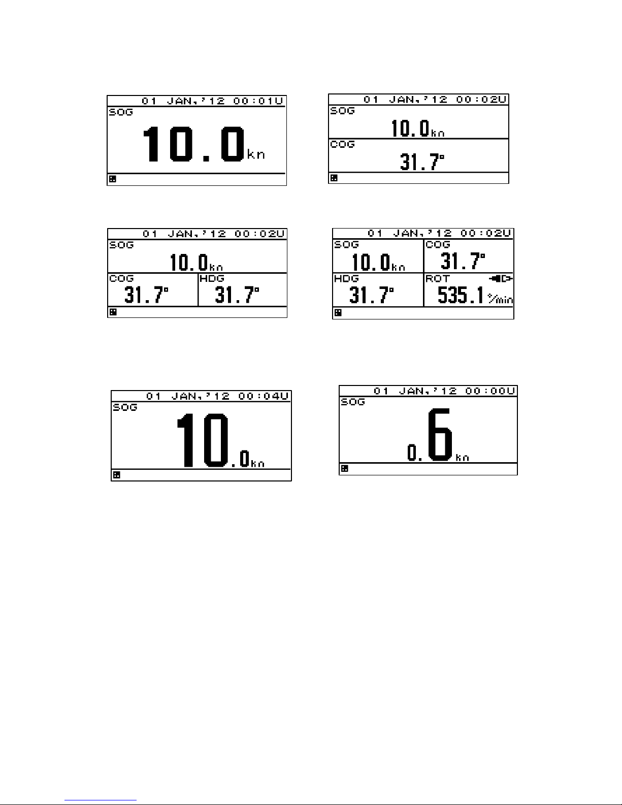
Setting a display mode
The display mode can be set only with segmentaion1 screen.
The contents of a display with an effective auto range are SOG, STW, ROT, depth, current, trip, and
total distance (ODO).
Even if it sets up an auto range by the other contents of a display, it becomes the normal display.
An auto range changes a display in the following range.
Auto range
The contents of a
display
Integer part expanded
display
Usual display Decimal part
expanded display
SOG/STW 10kn or more 1.0 - 9.9kn 0.9kn or less
ROT
More than 600°/ min 1.0-599.9° / min 0.9°/ min or less
Depth 10 m or more 9.9m or less -
Tot a l d is tan ce /
Trip
10NM or more
1.00 - 9.99NM
0.99NM or less
Current 10kn or more 1.0 - 9.9kn 0.9kn or less
1. The contents of a display are set up with the above-mentioned operating procedure.
2. Select the “ DISPLAY MODE” by using and press .
3. Select the “NORMAL”, SPECIAL1“”, “SPECIAL2” or “AUTO RANGE” by using and
press .
Example) SOG display
Integer part expanded display Normal display Decimal part expanded display
4.5.5. Selecting a back light color
Select white or orange as the back light color of the screen that is normally used.
Procedure
1. Display a main menu by pressing
.
2. Select “1. DISPLAY” and “BACK LIGHT” in this order by using
.
3. Select “WHITE” or “ORANGE” by using
and press .
Page 44

4-22
4.5.6. Setting graph scale
The vertical axis and horizontal axis scale of the water temperature and water depth graphs can be set.
For detail screen, refer to page 2-2.
Horizontal axis setting
TIME: The maximum display time of the horizontal axis is set.
The time that can be set is 5 minutes, 10 minutes, 20 minutes, and 30 minutes.
Vertical axis setting
MAX: The maximum value of the display value is set.
MIN: The minimum value of the display value is set.
Procedure
1. Press the
key to display the main menu.
Water depth
2. Press the
key to select “DISPLAY,” “GRAPH SCALE,” and “DEPTH” in order.
3. Press the
key to enter “TIME,” “MAX,” or “MIN,” and press the key.
Water temperature
2. Press the
key to select “DISPLAY,” “GRAPH SCALE”, and “WATER TEMP” in order.
3. Press the
key to enter “TIME,” “MAX,” or “MIN,” and press the key.
4.5.7. Registering user display
From among the screens registered in the display screen, the user display assigned to the
key
can be registered.
Procedure
1. Press the
key to display the main menu.
2. Press the
key to select “1.DISPLAY” and “USER DISPLAY” in order.
3. Press the
key to select the screens to be registered from “DISPLAY1” to “DISPLAY6,” and
press the
key.
Page 45

4-23
4.6. System Settings
Select “SYSTEM” on the main menu to display the system settings screen.
To change the system settings, place the unit in maintenance mode.
An overview of each submenu is as follows.
1) UNIT: Set the units of distance/ship speed, temperature, water depth, and wind velocity.
2) TIME DIFF: Set the time difference between UTC and local time.
3) DATA DISP: Select the date format.
4) LORAN C: Convert latitude and longitude to LORAN C time difference.
5) DEPTH: Set the position and offset of the transducer that displays the water depth.
4.6.1. Selecting units
You can set the units of distance/ship speed to NM, kn, km, km/h, mi, mi/h or m, m/s.
You can set the unit of temperature to °C or °F.
You can set the unit of water depth to m, ft or fm.
You can set the unit of wind velocity to kn, km/h, mi/h or m/s.
Procedure
1. Refer to “4.9.1 Changing to a maintenance mode” to display the maintenance menu.
2. Press the
key to select “SYSTEM” and “UNIT” in order.
3. Press the
key to select “DIST/SPD,” “TEMP,” “DEPTH” or “WIND.”
4. Press the
key to select the unit, and press the key.
Speed Distance
Water Temperature Wind
Depth
Page 46

4-24
4.6.2. Setting the time difference
You can set the time difference between UTC and local time.
For Japan, the time difference is +9 hours, so you would input +09:00.
When a time difference is set, “L” is displayed on the upper right of the screen.
Procedure
1. Refer to “4.9.1 Changing to a maintenance mode” to display the maintenance menu.
2. Press the
key to select “SYSTEM” and “TIME DIFF” in order.
3. Press the
key to enter the time difference, and press the key.
Local time
+9 hour
Time difference
+9 hour
Page 47

4-25
4.6.3. Setting date display format
You can set the date display format to “DD MMM,'YY,” “MMM DD,'YY,” or “'YY-MMM-DD.”
YY: Year MMM: Month DD: Day
Procedure
1. Refer to “4.9.1 Changing to a maintenance mode” to display the maintenance menu.
2. Press the
key to select “SYSTEM,” “DATE DISP,” and “TIME DISP” in order.
3. Press the
key to select the date display format, and press the key.
4.6.4. Displaying as loran c time difference
The latitude and longitude can be displayed as RORAN C time difference.
Procedure
1. Refer to “4.9.1 Changing to a maintenance mode” to display the maintenance menu.
2. Press the
key to select “SYSTEM,” “LORAC C,” “LORAN C” in order.
3. Press the
key to select “ON.”
4. Set the GRI, TD1, TD2, TD1 CORR and TD2 CORR.
4.6.5. Setting transducer position of depth sounder (exclusive to JFE-380/680)
Select which transducer is used to display the measured water depth in the water depth value output
from depth sounder JFE-380/680.
This function is used to select the transducer position of the water depth value in the depth sounder
screen.
The transducer position that can be selected is Forward “FWD,” Medium “MID,” and Backward (AFT).
For detail screen, refer to page 2-3.
Procedure
1. Refer to “4.9.1 Changing to a maintenance mode” to display the maintenance menu.
2. Press the
key to select “SYSTEM,” “DEPTH,” and “TRANS” in order.
3. Press the
key to enter the transducer position, and press the key.
DD MMM YY format
MMM DD YY format
YY MMM DD format
Page 48

4-26
4.6.6. Setting water depth offset of depth sounder
You can set an offset in the received water depth value.
The offset that can be set is ±99.9 m.
When an offset is set, the received water value with the offset value added is displayed.
Procedure
1. Refer to “4.9.1 Changing to a maintenance mode” to display the maintenance menu.
2. Press the
key to select “SYSTEM,” “DEPTH,” and “OFFSET” in order.
3. Press the
key to enter an offset, and press the key.
Offset 10m
Page 49

4-27
4.7. Language Settings
You can set the display language to nine languages (English/Japanese (katakana)).
To change the language, place the unit in the maintenance mode.
A maximum of nine languages: Other than English / Japanese, it is due to add one by one.
Procedure
1. Refer to “4.9.1 Changing to a maintenance mode” to display the maintenance menu.
2. Press the
key to select “LANG” and “LANG” in order.
3. Press the
key to select the language, and press the key.
4.8. Alarm Settings
Selecting “ALARM” on the main menu displays the alarm setting screen.
When the set alarm occurs, the pop-up and the alarm icon “
” on the status bar alert the occurrence
of an alarm as well as the buzzer sounds. The screen lighting color can also be changed.
Pressing the
key stops pop-up, buzzer sound, and screen lighting, but the icon continues
appearing until the alarm has been resolved.
The unit must be placed in maintenance mode to change the alarm settings.
The following alarms can be configured.
1) SYSTEM: An alarm occurs when the system error occurs.
2) SPEED: An alarm occurs when the ship speed matches the set parameters.
3) TRIP: An alarm occurs when the distance matches the set parameters.
4) WATER TEMP: An alarm occurs when the water temperature matches the set parameters.
5) DEPTH: An alarm occurs when the water depth matches the set parameters.
6) WIND: An alarm occurs when the wind velocity matches the set parameters.
7) AIR TEMP: An alarm occurs when the air temperature matches the set parameters.
8) PRESSURE: An alarm occurs when the atmosphere matches the set parameters.
9) HUMIDITY: An alarm occurs when the humidity matches the set parameters.
When alarms are set to OFF, the alarm settings are cleared.
The alarm sound and screen brightness color when an alarm occurs can be set.
1) SOUND ON: The buzzer sounds when an alarm occurs.
OFF: The buzzer does not sound when an alarm occurs.
2) LCD COLOR ON: The screen brightness color changes when an alarm occurs.
OFF: The screen brightness color does not change when an alarm occurs.
If normal brightness color is set to white, it becomes orange, and vice versa.
Page 50

4-28
4.8.1. Setting the alarm range
An alarm occurs when the range is set and the value matches the set range.
You can select the range from OVER, UNDER, IN RANGE, and OUT RANGE depending on the alarm.
OVER: An alarm occurs when the value exceeds the set value.
UNDER: An alarm occurs when the value falls below the set value.
IN RANGE: An alarm occurs when the value is within the set range.
OUT RANGE: An alarm occurs when the value is outside the set range.
When setting the IN RANGE and OUT RANGE, set the upper limit and lower limit values.
When an alarm is set to OFF, alarm settings are cleared.
The alarm types and alarm range that can be set are as follows.
Alarm type Alarm range
OVER UNDER IN RANGE OUT RANGE OFF
SPEED
TRIP
– – –
WATER TEMP
DEPTH
WIND
– – –
AIR TEMP
PRESSURE
HUMIDITY
: Can be set.
Procedure
1. Refer to “4.9.1 Changing to a maintenance mode” to display the maintenance menu.
2. Press the
key to select “ALARM” and “ALARM TYPE” in order.
3. Set the alarm according to the alarm setting procedure.
4.8.2. Setting a system alarm
An alarm occurs when the system error occurs.
The following is an overview of the system error.
1) The data can not be received.
2) The data is invalid.
Procedure
1. Refer to “4.9.1 Changing to a maintenance mode” to display the maintenance menu.
2. Select “ALARM” and “SYSTEM” in this order by using
.
3. Select “ON” or “OFF” by using
and press .
4. Refer to “4.8.11 Setting a buzzer sound and screen back light” to set the alarm sound and screen
brightness.
Page 51

4-29
4.8.3. Setting a vessel speed alarm
When the vessel speed reaches the set range, the alarm is issued.
The range can be selected from OVER, UNDER, IN RANGE, and OUTRANGE.
OVER: An alarm is issued when the vessel speed reaches or exceeds the set speed.
UNDER: An alarm is issued when the vessel speed is equal to or slower than the set speed.
IN RANGE: An alarm is issued when the vessel speed is between the lower limit value and the upper
limit value.
OUT RANGE: An alarm is issued when the vessel speed is equal to or slower than the lower limit
value or equal to or higher than the upper limit value.
For IN RANGE and OUT RANGE, set the upper limit value and lower limit value.
Procedure
1. Refer to “4.9.1 Changing to a maintenance mode” to display the maintenance menu.
2. Select “ALARM” and “SPEED” in this order by using
.
3. Select “OVER, “UNDER”, “IN RANGE”, or “OUT RANGE” by using
.
4. Select "OVER", "UNDER", “MAXIMUM” or “MINIMUM” by using
.
5. Enter a vessel speed by using
and press .
6. Refer to “4.8.11 Setting a buzzer sound and screen back light” to set the alarm sound and screen
brightness.
4.8.4. Setting a TRIP alarm
An alarm is issued when the distance exceeds the set TRIP.
Procedure
1. Refer to “4.9.1 Changing to a maintenance mode” to display the maintenance menu.
2. Select “ALARM” and “TRIP” in this order by using
.
3. Select “OVER” by using
.
4. Select “OVER” by using
.
5. Enter a distance by using
and press .
6. Refer to “4.8.11 Setting a buzzer sound and screen back light” to set the alarm sound and screen
brightness.
Page 52

4-30
4.8.5. Setting the water temperature alarm
An alarm occurs when the water temperature exceeds the set value.
Procedure
1. Refer to “4.9.1 Changing to a maintenance mode” to display the maintenance menu.
2. Press the
key to select “ALARM” and “WATER TEMP” in order.
3. Press the
key to select “OVER,” “UNDER,” “IN RANGE,” or “OUT RANGE.”
4. Press the
key to select “OVER,” “UNDER,” “MAXIMUM,” or “MINIMUM.”
5. Press the
key to enter the water temperature, and press the key.
6. Refer to “4.8.11 Setting a buzzer sound and screen back light” to set the alarm sound and screen
brightness.
4.8.6. Setting the water depth alarm
An alarm occurs when the water depth exceeds the set value.
Procedure
1. Refer to “4.9.1 Changing to a maintenance mode” to display the maintenance menu.
2. Press the
key to select “ALARM” and “DEPTH” in order.
3. Press the
key to select “OVER,” “UNDER,” “IN RANGE,” or “OUT RANGE.”
4. Press the
key to select “OVER,” “UNDER,” “MAXIMUM,” or “MINIMUM.”
5. Press the
key to enter the water depth, and press the key.
6. Refer to “4.8.11 Setting a buzzer sound and screen back light” to set the alarm sound and screen
brightness.
4.8.7. Setting the wind velocity alarm
An alarm occurs when the wind velocity exceeds the set value.
Procedure
1. Refer to “4.9.1 Changing to a maintenance mode” to display the maintenance menu.
2. Press the
key to select “ALARM” and "WIND” in order.
3. Press the
key to select “OVER.”
4. Press the
key to select “OVER.”
5. Press the
key to enter the wind velocity, and press the key.
6. Refer to “4.8.11 Setting a buzzer sound and screen back light” to set the alarm sound and screen
brightness.
Page 53

4-31
4.8.8. Setting the air temperature alarm
An alarm occurs when the air temperature exceeds the set value.
Procedure
1. Refer to “4.9.1 Changing to a maintenance mode” to display the maintenance menu.
2. Press the
key to select “ALARM” and “AIR TEMP” in order.
3. Press the
key to select “OVER,” “UNDER,” “IN RANGE,” or “OUT RANGE.”
4. Press the
key to select “OVER,” “UNDER,” “MAXIMUM,” or “MINIMUM.”
5. Press the
key to enter the air temperature, and press the key.
6. Refer to “4.8.11 Setting a buzzer sound and screen back light” to set the alarm sound and screen
brightness.
4.8.9. Setting the atmosphere alarm
An alarm occurs when the atmosphere exceeds the set value.
Procedure
1. Refer to “4.9.1 Changing to a maintenance mode” to display the maintenance menu.
2. Press the
key to select “ALARM” and “PRESSURE” in order.
3. Press the
key to select “OVER,” “UNDER,” “IN RANGE,” or “OUT RANGE.”
4. Press the
key to select “OVER,” “UNDER,” “MAXIMUM,” or “MINIMUM.”
5. Press the
key to enter the atmosphere, and press the key.
6. Refer to “4.8.11 Setting a buzzer sound and screen back light” to set the alarm sound and screen
brightness.
4.8.10. Setting the humidity alarm
An alarm occurs when the humidity exceeds the set value.
Procedure
1. Refer to “4.9.1 Changing to a maintenance mode” to display the maintenance menu.
2. Press the
key to select “ALARM” and “HUMIDITY” in order.
3. Press the
key to select “OVER,” “UNDER,” “N RANGE,” or “OUT RANGE.”
4. Press the
key to select “OVER,” “UNDER,” “MAXIMUM,” or “MINIMUM.”
5. Press the
key to enter the humidity, and press the key.
6. Refer to “4.8.11 Setting a buzzer sound and screen back light” to set the alarm sound and screen
brightness.
Page 54

4-32
4.8.11. Setting a buzzer sound and screen back light
An alarm sound and the color of the screen back light at the occurrence of an alarm can be set.
When the back light color under the normal condition is set to white, the color is changed to orange and
when the back light color is set to orange, the color is changed to white.
1) SOUND ON: When an alarm occurs, the buzzer sound is emitted.
OFF: Even if an alarm occurs, the buzzer sound is not emitted.
2) LCD COLOR ON: When an alarm occurs, the back light color of the screen is changed.
OFF: Even if an alarm occurs, the back light color of the screen is not changed.
Procedure
1. Refer to “4.9.1 Changing to a maintenance mode” to display the maintenance menu.
2. Select “SOUND” by using
.
3. Select “ON” or “OFF” by using
and press .
4. Select “LCD COLOR” by using
.
5. Select “ON” or “OFF” by using
and press .
Select SOUND
Select LCD COLOR
Page 55

4-33
4.9. Setting Installation
After completing the installation that is described in Chapter 6, check the operation and set the details.
In the installation setting, implement the following operations according to the system specification of
the vessel.
1) Changing to a maintenance mode
2) Setting a model
3) Selecting a dimmer unit
4) Setting dimmer control linkage and data sharing
Setting RS-485ID
Setting a dimmer group
Setting data sharing
5) Setting the display screen
6) Setting daisy chain
4.9.1. Changing to a maintenance mode
Before starting installation, the mode must be changed to a maintenance mode to prevent an operation
error.
Change the mode to a maintenance mode by the initial operation.
Procedure
1. Display a main menu by pressing
(normal mode).
2. Press
and for 3 seconds.
3. The menu is changed to a maintenance menu (maintenance mode).
When the mode is changed to a maintenance mode, the [M] icon is displayed at the bottom of the
screen.
Normal mode
Maintenance mode
Figure 4.1 Transition of menu screens
Returning to a normal mode
When
and are pressed for 3 seconds or no operation is performed for 3 minutes, the
mode is reset to a normal mode.
When the power is turned on, the system starts in normal mode.
and 3 seconds
The [M] icon is
displayed.
Page 56

4-34
4.9.2. Setting a model
This display unit is set in the MID display unit.
When the model is set, the setting contents are initialized.
Procedure
1. Refer to “4.9.1 Changing to a maintenance mode” to display the maintenance menu.
2. Select “DISPLAY TYPE” by using
and press .
3. Select “MID” by using
and press .
4. When the following popup menu is displayed, press “YES”.
When “NO” is selected, the model setting is cancelled.
4.9.3. Selecting a dimmer unit
Specify whether an external dimmer unit (NCM-227) or a dimmer key is used for controlling the dimmer
unit of this display unit.
When an external dimmer unit is used, the contact input must be set to “DIMMER”. For the setting
method, see “4.9.6 Setting a contact port”.
When sharing a dimmer unit, set the same dimmer unit for the display units that share the dimmer unit.
Unless the same dimmer unit is set, linking cannot be performed.
To calibrate the external dimmer unit, refer to "7.1 Calibration of External dimmer unit "in service
manual.
Procedure
1. Refer to “4.9.1 Changing to a maintenance mode” to display the maintenance menu.
2. Select “DIMMER” by using
.
3. Select a dimmer unit by using
and press .
・When "LOG" is selected wrong, the following messages appears.
After the messages appears, press and for 8 seconds. The message is canceled.
Then, select "MID" again in the previous procedure.
・Don't turn off the power supply until the "INITIALIZING" disappears.
Caution
Please turn on
the power again.
Page 57

4-35
4.9.4. Dimmer linked control and data sharing with RS-485
By connecting display units with RS-485 network, dimmer control can be linked and data can be
shared.
To connect display units with RS-485 network, the display units must be identified by setting RS-485ID
in each display unit.
Up to 10 display units can be connected.
The same baud rate must be set for all the display units. Normally, the baud rate is set to 115200bps.
It is possible to select key control or control by an external dimmer unit for dimmer control. Display units
that are linked can be selected by classifying display units under dimmer control into groups.
However, the same control method such as key control or control using an external dimmer unit must
be applied among the display units that are linked. Up to 10 groups are allowed.
Data can be shared by outputting a NMEA sentence to the RS-485 network.
By sharing data, the same data can be displayed.
To output data, the data must be received from the external unit.
A typical connection example for implementing dimmer control and data sharing with RS-485 is shown
below. Refer to the setting reference section for the setting method.
The connection conditions of the connection example are as follows.
Display unit 1 Display unit 2 Display unit 3 Display unit 4
Setting
reference
section
RS-485ID 1 2 3 4 4.9.4.1
Dimmer control unit External
dimmer unit
External
dimmer unit
Dimmer key Dimmer key 4.9.3
Dimmer group 1 1 2 2 4.9.4.3
Input data RS-422 - - - Vessel speed 4.9.5.2
RS-485 Vessel speed Vessel speed Vessel speed - –
Output data RS-485 - - - Vessel speed 4.9.4.4
Baud rate [bps] 115200 115200 115200 115200 4.9.4.4
Screen display Vessel speed Vessel speed Vessel speed Vessel speed 4.5.4
In this example, dimmer control of ID1 and that of ID2 are linked by the external dimmer unit and
dimmer control of ID3 and ID4 are not linked.
Dimmer control of ID3 and that of ID4 are linked by key operation and dimmer control of ID1 and that of
ID2 are not linked.
By transmitting vessel data that is input from ID4 through the RS-485 network, vessel speed data can
be displayed on all the display units.
Connection example
ID1 ID2 ID3 ID4
Group 1 Group 2
RS-485 network
RS-422
Vessel speed data
Vessel speed data
External dimmer unit
Page 58

4-36
4.9.4.1. Setting RS-485ID
To identify a display unit on the RS-485 network, set an ID for each display unit.
To use RS-485, an ID must be set.
Avoid duplication of ID among the display units. Otherwise, data and dimmer linkage are not possible.
Available IDs are from 1 to 10.
Procedure
1. Refer to “4.9.1 Changing to a maintenance mode” to display the maintenance menu.
2. Select “RS-485ID” by using
.
3. Enter an ID number by using
and press .
4.9.4.2. Linking dimmer control
Dimmer control linkage is available for the display units that are connected by the RS-485 network.
The following conditions are necessary for the linkage.
1) The display units must be connected by RS-485.
2) The same dimmer control is used.
3) The display units are in the same dimmer group.
Set the details by referencing the following sections.
1) Set RS-485ID by referencing “4.9.4 1 Setting RS-485ID”.
2) Select the same dimmer unit by referencing “4.9.3 Selecting a dimmer unit”.
3) Set the display units in the same dimmer group by referencing “4.9.4.3 Setting a dimmer group”.
To disable linkage of dimmer control even though the display unit is connected by the RS-485
network, change the dimmer group.
4.9.4.3. Setting a dimmer group
Set a group within which dimmer control for this display unit is linked.
Available dimmer group numbers are from 1 to 10.
Set a dimmer group when the display units for which dimmer control is to be linked need to be grouped
due to the different equipment environment even though the units are connected by RS-485.
Select the same dimmer unit within the same group. Otherwise, dimmer control cannot be linked within
the group.
Procedure
1. Refer to “4.9.1 Changing to a maintenance mode” to display the maintenance menu.
2. Select “DIMMER GROUP” by using
.
3. Enter a group number by using
and press .
Since dimmer data is transmitted between display units, some time lag may occur at dimmer
switching.
Caution
Page 59

4-37
4.9.4.4. Sharing data
Data can be shared among the display units that are connected through the RS-485 network.
Set the data to be transmitted. Although setting for reception is not necessary, the baud rate must be
standardized among the display units.
For the linkage, set RS-485ID by referencing “4.9.4.1 Setting RS-485ID”.
Setting transmission
Procedure
1. Refer to “4.9.1 Changing to a maintenance mode” to display the maintenance menu.
2. Select “INTERFACE”, “DATA I/O”, and “RS-485” in this order by using
.
3. Select the output format to be set by using
.
1) Selecting NMEA
4. When an output version is selected by using
, a sentence list is displayed.
Available versions are “1.5”, “2.1”, “2.3”, and “4.0”.
5. Select an output sentence by using
and set an output cycle.
A cycle can be selected within the range from 1 second to 9 seconds and if OFF is selected, the
sentence is not output.
6. Return control to the BIT RATE selection screen and select BIT RATE by using
.
Available bit rates are “38400”, “57600”, “76800”, and “115200”. Normally, “115200” is
recommended.
2) Selecting IEC
In IEC, VERSION is not selected.
4. When “SENTENCE” is selected by using
, a sentence list is displayed.
5. Select an output sentence by using
and set an output cycle.
A cycle can be selected within the range from 1 second to 9 seconds and when OFF is selected,
the sentence is not output.
Select an output format
Select VERSION (NMEA)
Select SENTENCE (IEC)
Select BIT RATE
Select an output
sentence
Select an output cycle
Sentence list
Page 60

4-38
6. Return control to the BIT RATE selection screen and select BIT RATE by using
.
Available bit rates are “38400”, “57600”, “76800”, and “115200”. Normally, “115200” is
recommended.
4.9.5. Setting a serial port
This display unit is equipped with three serial ports to send and receive data with external units. Since
each port can be set for input or output, set according to the purpose. However, as input/output of data
IN/OUT1 and data IN/OUT2 are commonly set, they cannot be set individually.
For instance, if data IN/OUT2 is set for input, data IN/OUT1 is automatically set for input.
In this case also, the baud rate and the output sentence can be set individually.
Determine the input output ports using the following table as the guideline.
Required port setting
Port setting
Data IN/OUT1 Data IN/OUT2 Data IN/OUT3
3 ports for output Output Output Output
3 ports for input Input Input Input
2 ports for output
1 port for input
Output Output Input
1 port for output
2 ports for input
Input Input Output
Although an output sentence, a cycle, and a bit rate can be set for each port, some bit rates and the
number of sentences may not be set. In this case, select the minimum sentence.
The following serial data can be set.
1) NMEA: Data is output in NMEA format. Available options are Version 1.5, 2.1, 2.3, and 4.0.
3) IEC: Data is output in IEC format.
Since data is transmitted between display units, some time lag occurs at the switching of
display.
Caution
Page 61

4-39
4.9.5.1. Setting transmission
The procedure for setting a serial port for transmission is shown below.
Procedure
1. Refer to “4.9.1 Changing to a maintenance mode” to display the maintenance menu.
2. Select “INTERFACE” and “DATA I/O” in this order by using
.
3. Select the output format to be set by using
.
1) Selecting NMEA
4. Select “SEND” from “DATA IN/OUT” by using
.
5. When an output version is selected by using
, a sentence list is displayed.
Available versions are “1.5”, “2.1”, “2.3”, and “4.0”.
6. Select an output sentence by using
and set an output cycle.
A cycle can be selected within the range from 1 second to 9 seconds and if OFF is selected, the
sentence is not output.
7. Return control to the BIT RATE selection screen and select BIT RATE by using
.
Available bit rates are “4800”, “9600”, “19200”, and “38400”.
Sentence list
Setting port
Select an output format
Select SEND
Select BIT RATE
Select VERSION
(NMEA only)
Select an output
cycle
Select an output sentence
BIT RATE selection screen
Page 62

4-40
When the "SEND" or "RECEIVE" of data IN/OUT1 or data IN/OUT2 is set and one port is set,
the other port is also set concurrently. The message that is shown below is displayed to
prevent the unintentional setting of the other port. When setting a port, select “YES”. If “NO”
is selected, the port is not set.
2) Selecting IEC
For IEC, there is no need to select VERSION.
4. Select “SEND” from “DATA IN/OUT” by using
.
5. Select an output sentence by using
and set an output cycle.
The cycle can be selected within the range from 1 second to 9 seconds and when OFF is selected,
the sentence is not output.
6. Return control to the BIT RATE selection screen and select BIT RATE by using
.
Available bit rates are “4800”, “9600”, “19200”, and “38400”.
Supplement
Page 63

4-41
When the "SEND" or "RECEIVE" of data IN/OUT1 or data IN/OUT2 is set and one port is set,
the other port is also set concurrently. The message that is shown below is displayed to
prevent the unintentional setting of the other port. When setting a port, select “YES”. If “NO”
is selected, the port is not set.
4.9.5.2. Setting reception
In the reception setting, set a bit rate.
There is no need to set a sentence or a cycle.
Procedure
1. Refer to “4.9.1 Changing to a maintenance mode” to display the maintenance menu.
2. Select “INTERFACE” and “DATA I/O” in this order by using
.
3. Select a port and a format that are to be set by using
.
4. Select “RECEIVE” from “DATA IN/OUT” by using
.
5. Select "BIT RATE" by using
.
Available bit rates are “4800”, “9600”, “19200”, and “38400”.
Setting port
Select an output format
Select RECEIVE
Select BIT RATE
Supplement
Page 64

4-42
4.9.6. Setting a contact port
4.9.6.1. Setting a contact input port
A contact input port can be set to the following input.
1) DIMMER: Use this option when connecting an external dimmer unit.
2) ACK: Alarm ACK is input from an external unit.
To use an external dimmer unit, the dimmer unit must be set to “EXT DIMMER”. See “4.9.3 Selecting a
dimmer unit” for the setting method.
Procedure
1. Refer to “4.9.1 Changing to a maintenance mode” to display the maintenance menu.
2. Select “INTERFACE”, “DATA I/O” and “CONTACT INPUT” in this order by using
.
3. Select an item to be input by using
and press .
4.9.6.2. Setting a contact output port
A contact output port can be set to the 400Pluse/NM or 200Pluse/NM input.
Procedure
1. Refer to “4.9.1 Changing to a maintenance mode” to display the maintenance menu.
2. Select “INTERFACE”, “DATA I/O” and “CONTACT OUTPUT” in this order by using
.
3. Select an item to be input by using
and press .
Page 65

4-43
4.9.7. Outputting alarm history
Alarm history can be output to an external unit.
Data is output from a data IN/OUT1 port.
If data IN/OUT1 is set to reception, the port must be set to transmission.
Connect PC to a serial port before output operation.
Procedure
1. Refer to “4.9.1 Changing to a maintenance mode” to display the maintenance menu.
2. Set DATA IN/OUT to “SEND” by referencing “4.9.5 Setting a serial port”.
3. Select “INTERFACE” and “DIAGNOSIS” in this order by using
.
4. When
is pressed at “ERROR LOG OUTPUT”, data is output to an external unit.
4.9.8. Checking installation
Installation can be checked.
The following items can be checked.
1) Checking the input port
2) Self-diagnosis
3) Display of alarm history
4) Confirmation of software version and serial number
See “4.9.7 Outputting alarm history” for external output of alarm history.
See "4.9.15 Outputting Setting value" for external output of setting value.
See “4.9.14 Demonstration” for setting a demo mode for confirmation of data output.
When DATA IN/OUT1 is used by setting to transmission, port setting is not required. At
completion of alarm history, the setting is reset to the original output data automatically.
Supplement
Supplement
Page 66

4-44
4.9.9. Checking the input port
Data that is received from the input port can be displayed on a screen.
The input port and display format (ASCII/BINARY) can be selected.
Data of the port that is set to output cannot be displayed.
Procedure
1. Refer to “4.9.1 Changing to a maintenance mode” to display the maintenance menu.
2. Select “MAINTENANCE” and “INPUT DATA” in this order by using
and press .
An operation description screen is displayed as shown below.
3. To change the display format press
. The format changes between ASCII and BINARY.
4. Select the port whose data is to be displayed by using
and press . The received data
is displayed on the screen. To cancel the display press
again.
During cancellation, the blinking of the *mark is stopped.
When no data is displayed, check the connection and the setting of the serial port.
4.9.10. Self-diagnosis
Self-diagnosis of the display unit can be performed and the result can be displayed.
The following items can be diagnosed.
1) ROM, RAM, and serial port of the display unit
2) Screen LCD
The entire screen is highlighted repeatedly such as black to white, white to black.
Check if some dots are omitted.
3) Buzzer sound
Checks if the buzzer sounds.
Procedure
1. Refer to “4.9.1 Changing to a maintenance mode” to display the maintenance menu.
2. Select “MAINTENANCE” and “DIAGNOIS” in this order by using
.
3. Select a diagnosis item by using
and press . The diagnosis is executed and the result
is displayed.
If you wish to stop the Screen LCD check, press .
*
Selected serial port
SIO[0]: Data IN/OUT1
SIO[1]: RS-485 port
SIO[2]: Sensor port
SIO[3]: Data IN/OUT2
SIO[6]: Data IN/OUT3
Selected
display format
Operation
description
screen
Display
Page 67

4-45
4.9.11. Displaying an alarm
The current alarm and past alarms can be displayed. Up to 40 past alarms can be stored and when the
number of alarms exceeds 40, alarms are deleted from the oldest one.
Procedure
1. Refer to “4.9.1 Changing to a maintenance mode” to display the maintenance menu.
2. Select “MAINTENANCE” and “ERROR LOG” in this order by using
.
Displaying the current alarm
3. Select “ALARM” by using
and press .
The current alarm is displayed.
When no alarm has occurred, no information is displayed.
Displaying past alarm history1
4. Press “ERROR LOG” by using
and press .
Alarm number
Alarm status
A: Occurred
K: ACK
Alarm contents
Indicates
that the display
continues.
Icon indicating that an
alarm is currently
occurring.
Alarm contents
Alarm status
A: Occurred
K: ACK
V: Cleared
Alarm number
Alarm occurrence date and time
When there is no date and time data available at the
time of alarm occurrence, no information is
displayed.
Page 68

4-46
4.9.12. Displaying the software version
The software version, serial number and bar code number of the display unit can be displayed.
Procedure
1. Refer to “4.9.1 Changing to a maintenance mode” to display the maintenance menu.
2. Select “MAINTENANCE”, “SOFT VERSION”, and “DISPLAY VER” in this order by using
.
Software version
Serial number
Bar code number
(Management number in the factory)
4.9.13. Performing master reset
This section describes how to perform master reset of the equipment.
Reset of water temperature and water depth
Reset of entire display unit
When master reset is performed, the setting values are reset to the default values. It is recommended
to keep the records of the setting values before performing master reset.
However, the following items are not reset.
Model, RS-485ID, daisy chain setting, dimmer control unit setting, dimmer group
Procedure
1. Refer to “4.9.1 Changing to a maintenance mode” to display the maintenance menu.
2. Select “MASTER RESET” by using
and press .
Page 69

4-47
4.9.14. Demonstration
Through a demonstration, display and external output are enabled in the same way as the actual
equipment operation.
Procedure
1. Refer to “4.9.1 Changing to a maintenance mode” to display the maintenance menu.
2. Select “DEMO MODE” and “DEMO TYPE” in this order by using
.
3. Select a DEMO condition and press .
4. Select "DEMO MODE" and "START" by using .
4.9.15. Outputting setting value
Setting value can be output to an external unit.
Data is output from a data IN/OUT1 port.
If data IN/OUT1 is set to reception, the port must be set to transmission.
Connect PC to a serial port before output operation.
Procedure
1. Refer to “4.9.1 Changing to a maintenance mode” to display the maintenance menu.
2. Set DATA IN/OUT to “SEND” by referencing “4.9.5 Setting a serial port”.
3. Select “INTERFACE” and “DIAGNOSIS” in this order by using
.
4. When
is pressed at “CONFIG OUTPUT”, data is output to an external unit.
4.9.16. Setting the current to be displayed
You can set the layer and data No. to be displayed.
The layer that can be displayed is up to three layers from the top.
Normally, set “LAYER” for use.
Procedure
1. Refer to “4.9.1 Changing to a maintenance mode” to display the maintenance menu.
2. Press the
key to select “CURRENT.”
3. Press the
key to select “LAYER,” and press the key.
4. Press the
key to select “DATA No.,” and press the key.
During execution of demonstration, [S] is displayed in blinking mode at the bottom of the screen.
To end demonstration, set “DEMO MODE” to “END” or turn off the power.
Supplement
When DATA IN/OUT1 is used by setting to transmission, port setting is not required. At
completion of alarm history, the setting is reset to the original output data automatically.
Supplement
Page 70

4-48
4.10. Setting daisy chain
The power can be distributed to up to three units from one power supply by setting daisy chain.
The display units in the same dimmer group can share the dimmer.
Power is not supplied to the fourth and subsequent units.
ON: Power is supplied to the next MID for daisy-chaining.
OFF: Power is not supplied to the next MID.
When output a data by daisy chain, set the "DATA IN/OUT4".
Procedure
1. Refer to “4.9.1 Changing to a maintenance mode” to display the maintenance menu.
2. Press the
key to select “DAISY CHAIN.”
3. Press the
key to select ON/OFF, and press the key.
Power cannot
be supplied
Be aware that when the MID fails or the power is turned off if the power is supplied in
daisy-chain mode, power cannot be supplied to the subsequent MID.
When the power is supplied in daisy-chain mode, the display unit closer to the power supply
starts to be activated, so it takes time for the second and subsequent display unit to be
activated.
When the "DAISY CHAIN" is set to "ON", "DATA IN/OUT1" is set automatically to "SEND",
also "DATA IN/OUT3" is set automatically to "RECEIVE".
Although it can be switched over with manual, it recommends that reception connection from
an external unit uses "DATA IN/OUT3".
Power
supply unit
Power
supply
Power
supply
CFQ-5768
Power supply
CFQ-5766A
Caution
Page 71

5-1
Chapter 5 Maintenance
Do not check or repair in this unit. Please call our field representative or your
nearest JRC office for inspection and repair services. Otherwise it may cause a
fire or an electric shock.
Do not remove the cover of this unit. Otherwise, you may touch a high-voltage
part and suffer from an electric shock.
Turn off the power on/off switch, and turn off the power supply breaker when you
check this unit for maintenance. Otherwise, a fire, an electric shock, or a failure
may occur.
Do not disassemble or modify this unit. Otherwise, a fire, an electric shock, or a
failure may occur.
In the event that you spill or drop any liquids or metals etc., turn off the unit, turn
off the power supply breaker, and contact your sales agent outlet or one of JRC
branch offices, sales centers or liaison offices. Continuing operation may cause
a fire, an electric shock or a malfunction.
In the event that smoking or burning odors are detected, immediately terminate
operation of the unit and contact your sales agent outlet or one of JRC branch
offices, sales centers or liaison offices. Never attempt to check or repair the unit.
Continuing operation may cause a fire or an electric shock.
Do not use an organic solvent such as thinner or benzine when you clean the
surface of the unit. For cleaning the surface, remove the dust and wipe with
clean dry cloth. Otherwise, the painting on the surface may be damaged.
WARNING
CAUTION
Page 72

5-2
5.1. Daily Maintenance
Do not remove the cover of this unit. Otherwise, you may touch a
high-voltage part and suffer from an electric shock.
Turn off the power on/off switch, and turn off the power supply
breaker when you check this unit for maintenance.」「an electric
shock. Otherwise, a fire, an electric shock, or a failure may occur.
Do not use an organic solvent such as thinner or benzine when
you clean the surface of the unit. For cleaning the surface,
remove the dust and wipe with clean dry cloth. Otherwise, the
painting on the surface may be damaged.
The life of the device depends on how daily maintenance and inspection are performed carefully.
To keep the device in the best condition at all times, it is recommendable to perform periodical
inspections constantly. Any failure in the device can be prevented before it occurs through such
inspections. Please perform the inspections shown in the table below periodically.
Remove stains from the panel face, knob, panel keys, top cover by wiping them lightly with dry
cloth.
Check knob, panel keys, loosening of the connector and starting the omission, and it tightens
correctly.
Check loosening and rattling of the screw bolt that is the fixation of the case, and it tightens
surely.
Operate the equipment under standard power voltage levels (DC 10.8 - 31.2 V).
WARNING
CAUTION
Page 73

5-3
5.2. Alarm
Refer to "4.9.11 Displaying an alarm" and check if any alarm is given or not. If it is, check the details
referring to the list shown below.
Alarm List
Message
Number
Message Contents Alarm Causes
2/3/7 SOG/STW/SOG(LOG) Speed alarm occurs
10 TRIP Trip alarm occurs
17 WATER TEMP Water Temperature alarm occurs
18 DEPTH Depth alarm occurs
19/20 TWS/AWS Wind alarm occurs
21 AIR TEMP Air temperature occurs
22 PRESSURE Pressure alarm occurs
23 HUMIDITY humidity alarm occurs
45 ROM[1] Flash ROM Deletion, Write Error (ROM[1])
46 ROM[2] Flash ROM Deletion, Write Error (ROM[2])
47 ROM[3] SEEPROM Deletion, Write Error
48 RAM RAM Read, Write Error
49 SIO[0] Serial Port Error (SIO[0])
50 SIO[1] Serial Port Error (SIO[1])
51 SIO[2] Serial Port Error (SIO[2])
52 SIO[3] Serial Port Error (SIO[3])
53 SIO[6] Serial Port Error (SIO[6])
- No Sensor Data Sensor periodic input not possible (No data)
- Sensor Data Invalid
Sensor information unobtainable (Position, Time,
Course, etc.)
Page 74

5-4
5.3. Troubleshooting for Malfunctions or Abnormalities
In the event that smoking or burning odors are detected,
immediately terminate operation of the unit and contact your sales
agent outlet or one of JRC branch offices, sales centers or liaison
offices. Never attempt to check or repair the unit. Continuing
operation may cause a fire or an electric shock.
The following is reference information concerning identification of problems.
Symptom Possible Causes Troubleshooting Measures
The power does not
turn on when the power
switch is pressed.
Power is not being supplied
by the ship junction box.
Check whether the cabling from the junction
box is normal.
Power is not being supplied
by the power supply
equipment (option).
Check whether the power supply unit cabling
is normal.
The fuse connected to the
power cable has blown.
If there are no problems in the cabling,
replace the fuse.
The power supply equipment
(option) fuse has blown.
If there are no problems in the cabling,
replace the fuse.
The display unit switch is
broken.
Consult with JRC or our agents.
The LCD display does
not display anything.
The LCD display is broken. Consult with JRC or our agents.
The display does not
light up.
The alarm sound is not
generated.
The buzzer is broken. Consult with JRC or our agents.
The alarm sound is turned off. Refer to 4.8.11
The click does not
sound.
The key press sound is
turned off.
Refer to 4.5.3
There is no reception
(from sensor).
The sensor connection cable
is disconnected.
Check the connection cable.
The sensor is broken. Consult with JRC or our agents.
There is no
transmission
(to external devices).
Output settings have not
been configured.
Refer to 4.9.5
The configured channel is
incorrect.
Refer to 6.3.1
The DISP-DPU or POWER
SUPPLY UNIT is broken.
Consult with JRC or our agents.
The Dimmer are not
interlocked.
The baud rate is different. Refer to 4.9.4.4
The dimmer group is
different.
Refer to 4.9.4.3
The dimmer is different. Refer to 4.9.3
The cable is disconnected. Check the connection.
Data is not shared.
The baud rate is different. Refer to 4.9.4.4
Output sentence is not
selected.
Refer to 4.9.4.4
The cable is disconnected. Check the connection.
WARNING
Page 75

5-5
5.4. Repair Unit
5.4.1. Repair unit
Repair units and their models are shown below.
No Name Model Notes
1 DSP UNIT CMJ-562
2 POWER UNIT CMP-490
3 LCD UNIT CCN-423
FUSE
No Name Model Notes
1 FUSE MF60NR 250V 1
for Data power cable
1A FUSE
Mechanical Parts
No Name Code Notes
1
FRONT PANEL
KIT
MPBC47673
FRONT PANEL
PRODUCT NAMEPLATE
5.4.2. Regular Replacement Parts
Parts which should be regularly replaced are shown below.
Contact JRC or an affiliate to order.
No Name Model Life Notes
1 LCD UNIT CCN-423 40000 hours
Approximately 5 years of
continuous use
Page 76

5-6
Page 77

6-1
Chapter 6 Installation
Consult with JRC or our agents to install. Installation by unauthorized personnel may
result in a malfunction.
Do not install this unit at the place exposed to direct sunlight for a long time or hit by hot
wind or where the temperature rises above 55℃. Otherwise it may cause a fire or a
breakdown.
Do not put the equipment on the unstable place such as wobbly base or tilted area.
Otherwise it may cause the equipment to drop or fall, resulting in an injury or a failure.
Do not put the equipment in the cabinet or cover it with the nonporous thing such as
cardboard. Otherwise it may cause the equipment to be filled with heat, resulting in a
fire or a failure.
When this unit is suddenly moved from a cool place to a warm place, drew
condensation water may form on the inside windows, and the liquid crystal part can
become visually difficult. In this case, leave the unit for a while until becoming dry
condition. Then operate the unit.
CAUTION
Page 78

6-2
6.1. Affixing Display Unit Nameplate Labels
6.1.1. Affixing product nameplate
Peel the label of the equipment to be used from the accessory product nameplate, and affix it to the
center of the front panel.
6.1.2. Affixing model identification plate
Peel the label of the equipment to be used from the accessory model identification plate, and affix it
over the upper left blank part of the unit nameplate at the center of the rear case.
After affixing model identification plate
Product Nameplate (Accessory)
Model Identification Plate
(Accessory)
Display Unit Front
Display Unit Rear
Page 79

6-3
6.2. Display Unit Installation
6.2.1. Selecting the position for installation
Install this unit at least 1 m away from any magnetic compasses. Installation near a
magnetic compass may interfere with the magnetic compass, resulting in an accident.
Do not use this unit at the voltage other than its rated voltage.
Otherwise it may result in a fire, an electric shock or a failure.
Use the indicated screws when installing the display unit to a stable woodensurface.
Otherwise it may cause the display to fall down, resulting in an injury or a property
damage.
During installation, be sure to connect the earth plate and earth cable to the earth
terminal. Otherwise it may cause an electric shock in case of failure or electric leak.
Do not use or leave the equipment at the place exposed to direct sunlight or hit by hot
wind for a long time or where the temperature becomes 55℃ or higher. Otherwise it
may cause a fire or a failure.
Do not put the equipment on the unstable place such as wobbly or tilted area.
Otherwise it may cause the equipment to drop or fall, resulting in a fire or a failure.
Do not put the equipment in the cabinet or cover it with the nonporous thing such as
cardboard. Otherwise it may cause the equipment to be filled with heat, resulting in a
fire or a failure.
Use the proper power cable, signal cable, and earth cable. Otherwise it may cause this
unit to damage t other equipment.
WARNING
CAUTION
Page 80

6-4
6.2.2. Mounting the display unit using a rack
Use the following procedure.
(1) Fix the desktop rack at the required installation position by using the mounting screws (φ4~6
screw or wood screw, L>=15mm, provided by the shipyard).
(2) Insert the front panel into the main unit.
(3) Attach the rotational washer on the side of the main unit.
(4) Attach the rotational washer on the side of the desktop rack.
(5) Assemble the main unit on the desktop rack, insert the knob metal washer between the desktop
rack and the knob bolt, and fix the main unit by tightening the knob bolts.
Front panel
Main unit
Rotational
washer
6 mounting hole (4 holes)
Desk rack
Knob metal washer
Knob bol
t
Mounting screw
(provided by the shipyard)
Page 81

6-5
Required installation space
(Unit: mm)
Mount (bottom)
285 or more 190 or more
190 or more
Page 82

6-6
6.2.3. Mounting using a flash mount
Use the following procedure.
See the diagram below for the mounting space and mounting holes.
Do not tighten a screw too much. Doing so may result in damage of installation holes.
(1) Insert the main unit in the installation location
(2) Fix the main unit using the mounting screws (φ4 screw or wood screw, L>=10mm, provided by the
shipyard).
The sizes of the heads of the screws that are used are restricted as follows including the washers.
Diameter: Up to 8 mm
Height: Up to 4.5 mm
(3) Insert the front panel into the main unit
Front panel
Mounting
screw
(provided by
the shipyard)
After mounting
4.5 mounting
hole (4)
Main unit
Mounting wall
Page 83

6-7
Provide maintenance space
or more
※About the corner C11,
may want to cut φ25
Mounting hole
(Square hole)
(Screw pitch)
(Square hole)
(Screw pitch)
Page 84

6-8
6.2.4. Removing the display unit by flash mounting
Use the following procedure to remove the display unit.
(1) Insert a hexagonal wrench into the holes (2) at the bottom of the front panel.
(2) Remove the front panel by pressing down the hexagonal wrench.
Mounting wall
Front panel
Prepare a board to protect
the wall from being
damaged.
Hexagonal wrench
Recommended size: 3 mm
Press down
Page 85

6-9
6.3. Cable Connection
Unit (Rear Connector)
[SENSOR/DATA 2]
Daisy chaining
Or, connect with external device.
[DATA 1]
Share data between display units
[DC12/24V DATA]
Power Input Terminal
Used fro power input to unit.
Be sure to connect specified data power cable.
External Equipment Connection Terminal
(Contact Output Signal)
Connect to the optional equipment such as external
buzzer.
External Equipment Connection Terminal
(Contact Input Signal)
Connect to the contact input and external dimmer.
External Equipment Connection Terminal
(Serial Transmission I/O)
[E]
Chassis Earth Terminal
Connect to ship earth
[TERM.]
Turn ON and OFF terminal
resistance for DATA1
connection
Page 86

6-10
6.3.1. DC12/24V DATA connector
表示器 背面
Terminal Number
(CFQ-5766)
Name Explanation
1 Red
DC12/24V
DCIN +
Connect the accessory power cable.
The power-supply voltage range is 10.8 to 31.2 VDC.
2 Black DCIN 3 Orange
Contact
Output
ALM_COM
Output contact signals
4 Yellow ALM_NO
5 Green ALM_NC
6 Blue
Contact Input
Analog Input
ACK_IN+
Input contact signal or external dimmer.
7 Purple ACK_IN8 Gray Serial
Transmission
(DATA I/O 1)
SD0-A Input and output to the specifications set by “DATA
IN/OUT1.”
9 White SD0-B
10 Pink Serial
Transmission
(DATA I/O 2)
SD3-A Input and output to the specifications set by “DATA
IN/OUT2.”
11 Sky blue SD3-B
12 Bright
green
Serial
Transmission
(DATA I/O 3)
SD6-A
Input and output to the specifications set by “DATA
IN/OUT3.”
13 Brown SD6-B
14 Black
(Shield)
Chassis
Earth
E
Chassis earth
CFQ5766
1A
1A
+
-
Red
Black
Fuse Holder
(Containing 1A Fuses)
Data Power Cable
CFQ-5766A: 2 m (Accessory)
CFQ-5766D: 10 m (Option)
CFQ-5766F: 20 m (Option)
14 13
12 11 10
9 8 7 6
5 4 3
2 1
Display Unit Rear:
Connector Pin Number
Page 87

6-11
[Input/Output Condition for Serial Transmission]
The data power cable (CFQ-5766) has three serial transmission channels.
The input/output settings for DATA I/O "1" and "2" are linked to each other.
As listed below, four connections and settings can be made.
For the input/output settings for channels, see "4.9.5 Setting a serial port".
Terminal Number
(CFQ-5766)
Name
Input/Output Condition
3ch
Input
2ch Input
1ch Output
1ch Input
2ch Output
3ch Output
8 Gray
Serial
Transmission
(DATA I/O 1)
SD0-A
Input Input Output Output
9 White SD0-B
10 Pink Serial
Transmission
(DATA I/O 2)
SD3-A
11 Sky blue SD3-B
12 Bright green Serial
Transmission
(DATA I/O 3)
SD6-A
Input Output Input Output
13 Brown SD6-B
データ電源ケーブル
CFQ-5766A : 2m (付属品)
CFQ-5766D : 10m (オプション)
CFQ-5766F : 20m (オプション)
CFQ5766
1A
1A
+
-
Data Power Cable
CFQ-5766A: 2 m (Accessory)
CFQ-5766D: 10 m (Option)
CFQ-5766F: 20 m (Option)
Page 88

6-12
[Input/Output Circuit]
NCM-227
Dimmer Unit
NWZ-4610 Display Unit
IEC61162-1 (NMEA)
SD-B
SD-A
SD-B
SD-A
Input Setting
Output Setting
Relay
Contact maximum 30 VDC/1.0 A
COM
NO
NC
IEC61162-1 (NMEA)
Input
Output
[Serial Transmission]
[Contact Output]
[Contact Input/Analog Input]
IN+
IN-
1
2
3
4
or Contact Connection
3: Orange
4: Yellow
5: Green
6: Blue
7: Purple
Page 89

6-13
6.3.2. DATA1 connector
Display Unit Rear
Terminal
Number
(CFQ-5769)
Name Explanation
1 Brown
Serial
Transmission
(RS-484)
SD1-A
Connect to the display unit for serial transmission
2 Red SD1-B
3 Green SD1-C
4 Shield Chassis Earth E Chassis earth
[TERM. Switch]
When this terminal is connected, move the TERM. switch (terminator) to ON.
To connect multiple units, move the TERM. switches on both ends of the display unit to ON.
1 4
2 3
Display Unit Rear: Connector Pin Number
CFQ5769
Data Cable
CFQ-5769: 3 m (Option)
ON
(上)
ON
OFF
(下)
TERM. Switch
When the rubber cap
is removed, the switch
appears.
(Up)
(Down)
Page 90

6-14
[T-SHAPED CONNECTOR]
This T-SHAPED CONNECTOR can be used to extend cables and connect multiple units (up to 10
units).
[To Extend the Cable]
T-SHAPED CONNECTOR (option)
Type name: AA-040404-MMM-TL
Code: 5JCDX00071
CFQ-5769
CFQ-5769
CFQ-5769
CFQ5768CFQ5768
CFQ-5769: 3 m
CFQ-5769: 3 m
Term.: ON (up)
Term.: ON (up)
CFQ-5769: 3 m x necessary number of cables
and
T-SHAPED CONNECTOR Same number as
CFQ-5769
Page 91

6-15
[To Connect Multiple Units]
Up to 10 units can be connected.
... 3 . 4 . 5 . 6 . 7 . 8 . 9 ...
CFQ5768
CFQ-5769: 3 m
CFQ5769
CFQ5768
Term.: ON (up) Term.: ON (up)Term.: OFF (down)
CFQ-5769: 3 m
CFQ-5769: 3 m
The number of cables and the number of T-SHAPED
CONNECTOR vary depending on the distance between
display units.
Page 92

6-16
[To Group Dimmer Control]
The following shows an example of grouping 10 units (maximum number of connections) into 3 units, 3
units, and 4 units.
Dimmer group: 01
Dimmer: Key
Dimmer group: 02
Dimmer: External dimmer
Dimmer group: 03
Dimmer: Key
RS485ID:06 RS485ID:05
RS485ID:02
SOG
12.3 kn
SOG
12.3 kn
SOG
12.3 kn
RS485ID:01 RS485ID:03
RS485ID:04
RS485ID:09 RS485ID:08 RS485ID:07
SOG
12.3 kn
SOG
12.3 kn
SOG
12.3 kn
RS485ID:10
SOG
12.3 kn
SOG
12.3 kn
SOG
12.3 kn
SOG
12.3 kn
NCM-227
Dimmer unit
DIMMER
Key operation
Key operation
Volume control
CFQ-5769: 3 m
Page 93

6-17
6.3.3. SENSOR/DATA2 connector
[For serial communication with external device]
Display Unit Rear
Terminal
Number
Name Explanation
1 -
Unused
2 3 White Serial
transmission
DATA IN 4
RXD2-B
Input to the specification set by “DATA IN/OUT4.”
4 Green RXD2-A
5 Yellow Serial
transmission
DATA OUT 4
TXD2-A
Output to the specification set by “DATA IN/OUT4.”
6 Brown
TXD2-B
1 5
6
2 4
3
Display Unit Rear: Connector Pin Number
CFQ5767
Data cable
CFQ-5767: 3 m (option)
Page 94

6-18
[For outputting together four data from one port]
Display Unit Rear
Terminal
Number
(CFQ-5767)
Name Example
3 White Serial
transmission
DATA IN 4
RXD2-A
Input Position
4 Green RXD2-B
5 Yellow Serial
transmission
DATA OUT 4
TXD2-A
Output
Position/
water depth
Water
temperature/
current
6 Brown
TXD2-B
Terminal
Number
(CFQ-5766)
Name
Setting Example
3ch input
8 Gray
Serial transmission
(DATA I/O 1)
SD0-A
Input
Water depth
9 White SD0-B
10 Pink
Serial transmission
(DATA I/O 2)
SD3-A
Water
temperature
11 Sky blue SD3-B
12 Bright
green
Serial transmission
(DATA I/O 3)
SD6-A
Input Current
13 Brown SD6-B
CFQ5767
CFQ5766
1A
1A
+
-
Output together from this port
DATA IN 1
DATA IN 2
DATA IN 3
DATA IN 4
NWZ-4610
display unit
DATA OUT 4
Page 95

6-19
[To daisy-chain the units]
Display Unit Rear
Terminal
Number
(CFQ-5768)
Name Example
1 Red
Power supply
output
DCOUT+
Supplies the power to the subsequent display unit.
2 Black DCOUT3 White Serial
transmission
DATA IN 4
RXD2-B
Receives data from the subsequent display unit.
4 Green RXD2-A
5 Yellow Serial
transmission
DATA OUT 4
TXD2-A
Sends data to the subsequent display unit.
6 Brown
TXD2-B
CFQ5768
1 5
6
2 4
3
Display Unit Rear: Connector Pin Number
Data cable
CFQ-5768: 3 m (option)
(1)
(2)
(3)
(4)
(5)
(6)
(1)
(2)
(9)
(8)
(12)
(13)
(14)
Red
Black
White
Green
Yell ow
Brown
6 pins
14 pins
Page 96

6-20
Up to three units can be daisy-chained.
To make this connection, set the daisy-chain setting to ON.
CFQ5766
1A
1A
+
-
CFQ5768
CFQ5768
Data power cable
CFQ: 5768: 3 m (option)
Display Unit Rear
14 pins
6 pins
Data power cable
CFQ-5768: 3 m (option)
Power
supply
Data power cable
CFQ-5766A: 2 m (accessory)
CFQ-5766D: 10 m (option)
CFQ-5766F: 20 m (option)
Page 97

6-21
6.4. Optional Peripheral Connection
6.4.1. Dimmer unit connection
The brightness of the backlight can be changed at a location away from the display unit by connecting
the dimmer unit (NCM-227).
To calibrate the external dimmer unit, refer to "7.1 Calibration of External dimmer unit "in service
manual.
NCM-227 Dimmer Unit
NWZ-4610
Display Unit
DC12/24V
CFQ-5766A
Data Power Cable
(2 m)
DC12/24V DATA
DATA1
SENSOR
/DATA2
CQD-10
Junction Box
1
2
3
4
5
6
7
8
9
10
11
12
1
2
3
4
Blue
Purple
Fuse Holder
Fuse Holder
+
-
Red
Black
Page 98

6-22
Page 99

7-1
Chapter 7 After-Sales Service
7.1. When Ordering a Repair
When a failure has been detected, stop operation and contact the dealer or agent from which
you purchased the device or one of our branches, marketing offices, and representative
offices.
Repair during warranty period Should a malfunction occur when the unit has been operated
according to descriptions and instructions in the instruction manual, it will be repaired free of
charge. However, breakdowns resulting from abuse, negligence, natural disaster, fire or other
unforeseeable incident will be charged.
Repair after warranty period Repairs that restore normal operation made after the warranty
period have to be paid in full by the client.
Product data that should be provided when you ask for service
Name of product, model, date of manufacture and serial number
Description of malfunction (as detailed as possible)
Company address or name of organization, address and telephone number
7.2. Recommendation of Overhaul
The performances of the set may deteriorate due to the aging of parts, and so on through the
rate varies depending on the conditions of use. So it is recommendable to contact the dealer
from which you purchased the device or one of our marketing offices for overhaul apart from
daily service.
Incidentally, such overhaul will be performed with charge.
Please contact the dealer from which you purchased the device or our marketing office that is
nearest to you for any question as to the after-sales service.
Page 100

7-2
 Loading...