

JRC JR-8600, NWZ-1650 Instruction Manual

JLR-8600
NWZ-1650
GPS NAVIGATOR
INSTRUCTION
MANUAL
i

Foreword
Thank you for purchasing the JRC GPS Navigator JLR-8600.
This equipment is a high-performance navigation equipment consisting of a GPS sensor and
navigator, can retrieve the position data using the GPS sensor to display various navigation
information on the display.
● Thoroughly read this instruction manual before operating the equipment.
● Keep this manual nearby the equipment to allow ready access to it if necessary. It may
provide valuable information on how to deal with a given situation that may arise during the
operation.
ii
Symbols
Several symbols are used in this manual to ensure safety and proper operation of the
equipment and to avoid possible human injury or property damage. These symbols and
their meanings are shown below. Please read and understand these symbols before
proceeding to read this manual.
Before Commencing the Operation
WARNING
CAUTION
Examples of the Symbols
The symbols shown in the ∆ mark represent those that require attention
(including potential dangers and warnings).
A depiction of the type of caution is shown inside the symbol (the left symbol
indicates a general caution).
The symbols shown in the mark represent actions which are prohibited.
A depiction of the type of prohibited action is shown inside the symbol (the
left symbol indicates that disassembly is prohibited).
Instructions shown with this symbol represent what can cause
death or serious injury if not observed.
Instructions shown with this symbol represent what may cause
injury or property damage if not observed.
The symbol indicates required actions. A depiction of the type of required
action is shown inside the symbol (the left symbol indicates that the power
plug must be disconnected from the outlet).
iii
Precautions Upon the Operation
WARNING
Do not disassemble or modify the equipment. Doing so may result in fire, electric
shock, or equipment failure.
Do not allow the display to become wet. Doing so may result in fire, electric
shock, or equipment failure.
Operate the equipment only at the indicated voltage. Failure to do so may result
in fire, electric shock, or equipment failure.
Install this unit at least 1 m away from any magnetic compasses. Installation near
a magnetic compass may result in interference with the magnetic compass, and
may result in an accident.
Do not perform internal inspections or modifications of the equipment. Inspection
or modification by unauthorized personnel may result in fire, electric shock, or
equipment failure. Please consult with JRC or an affiliate to perform internal
inspections or repair.
When disposing of the used lithium battery, place insulating tape over the battery
terminals, or otherwise insulate the battery. Failure to do so may result in heating,
explosion, or fire due to a shorted battery.
iv
CAUTION
This equipment is not designed to automatically make judgments on the position
data. The navigation information including the position data needs to be judged by
the user himself.
Do not use the equipment in the environment other than those provided in the
specification. Doing so may result in equipment failure, malfunction, or injury.
Do not install the display unit in the location where it may come in contact with
water, oil, or chemicals. Doing so may result in equipment failure, malfunction, or
injury.
Do not install the equipment in the place subject to vibration or shock.
Doing so may result in the equipment falling or collapsing, resulting in equipment
failure or injury.
Do not place any item on the top of the equipment.
Doing so may result in equipment failure, malfunction, or injury.
Please consult with JRC or an affiliate to perform installation. Installation by
unauthorized personnel may result in malfunction.
Use only the specified battery. Failure to do so may result in battery leakage or
rupture, resulting in fire, injury, or equipment failure.
Do not use benzine, alcohol or thinner when caring this equipment.
Doing so may result in removing the paint or changing of properties.
Wipe off the grime lightly with a dry soft cloth.
Use the indicated screws when installing the display unit to a stable wooden
surface. Failure to do so may result in the display unit falling over, causing injury
or property damage.
Use only the specified fuse.
Failure to do so may result in fire or equipment failure.
Use only the specified battery.
Failure to do so may result in equipment failure or malfunction.
v
When connecting the cable attached to the equipment, do not bend it acutely, twist
it, or impart excessive force. Doing so sometimes causes cracks or damage to the
coating, resulting in fire or electrocution.
Do not install the sensor where there is excessive vibration.
Vibration may cause sensor failure.
Do not paint the sensor.
Doing so may result in reception problems.
Do not install the sensor where temperature exceeds 55 degrees Celsius and
there is covered with exhaust gas from funnel. Doing so may result in flood and
cause sensor failure.
The junction box rubber gaskets (25 f Gland side) fit 10mm – 20mm cables.
Install the sensor where there are no obstacles, in order to ensure that GPS signals
can be directly received from satellites without interference or reflection of signals
from surrounding objects.
Whenever possible, select a place with the following characteristics.
1. An open space, which allows uniform reception of satellite signals.
2. Far away from any high power transmission antennas.
3. Outside radar beams.
4. Away from the INMARSAT antenna by at least 5 meters and outside
If it is difficult to find an ideal site, select a place temporarily and install the equipment. Conduct a test to make
sure that the proper performance can be obtained and then fix the equipment in position. If it is installed at an
improper place, reception accuracy may be impaired.
vi
the INMARSAT beam.
5. Away from the antenna of a VHF transmitter and a direction finder
by at least 3 meters.
6. Away from a Magnetic Compass by at least 1 meter.
7. 3 meters or more away from amateur radio antennas.
If occurs bad positioning of such as satellite can not be received, please execute the
master reset of sensor.
There are cases when time lags in the gps navigator and gps compass.
This is not a malfunction due to the delay in the internal processing.
There are cases when time lags in the main display unit and sub display unit.
This is not a malfunction due to the delay in the internal processing.
CAUTION
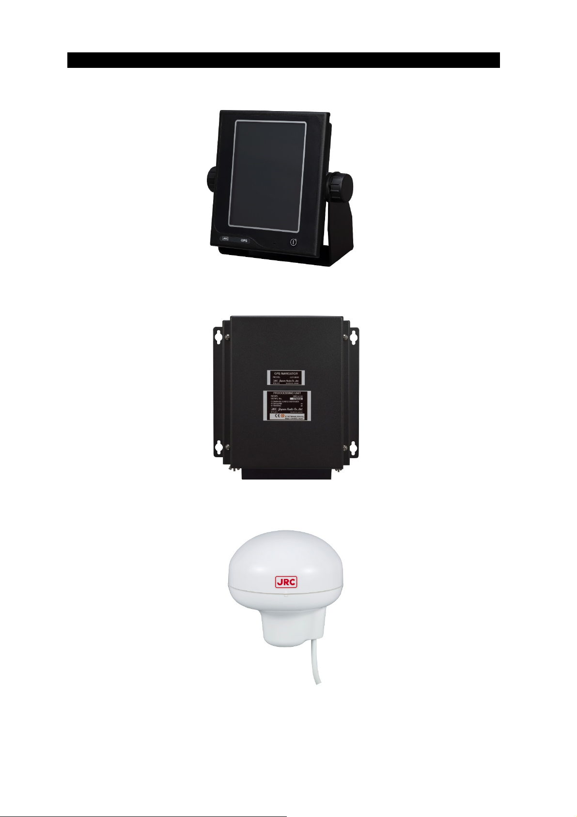
Appearance of the Equipment
●NWZ-1650 Display Unit
●NDC-4100 Processor Unit
●JLR-4350 GPS Sensor Unit
vii

Terminology
Term Meaning (Descriptions)
2D (2 dimension) Positioning with antenna elevation height in addition to satellite
data.
3D (3 dimension) The three dimensional position fix, 4 or more satellites required.
Active route Route that is currently used by a ship
Anchor alert This alert monitors that the own ship is the preset distance or more
away from the waypoint.
Arrival alert This alert informs that the own ship has traveled the preset distance,
approaching the waypoint.
Beacon information Beacon data which is broadcast by message type 16.
BeiDou
Boundary alert This alert informs that the own ship has got into the preset route.
CCRP Abbreviation of Consistent Common Reference Point. Reference
CDI Abbreviation of Course Deviation Indicator. This indicator shows
Checksum An error detection method to check that the data has been correctly
COG Course Over Ground.
Course Direction in which the ship is traveling, which is the bearing mainly
CURRENT Sea and ocean currents, expressed in speed and direction.
Data route Ship route data that is stored in the memory of the equipment
Default gateway Equipment connected externally from a constructed network.
DGPS Abbreviation of Differential Global Positioning System. GPS
BeiDou is a satellite positioning system that is managed by China.
position of the own ship.
information on the deviation from the scheduled route and on the
direction into which the ship should be steered.
transmitted.
displayed by the GPS.
satellite error data sent from a reference station whose position is
accurately known is received via beacon from a beacon station,
improving positioning accuracy.
DISP-DPU The main circuitry of display unit.
FRAM Nonvolatile memory using a ferroelectric substance.
Geodetic Conditions for expressing position via latitude and longitude.
GPS Satellite (GPS) Abbreviation of Global Positioning System. Refers to satellites
launched for navigational support of military vessels managed by
the United States Department of Defense.
GLONASS
HDOP Abbreviation of Horizontal Dilution of Precision. Indicates accuracy
IEC IEC is the abbreviation of International Electrotechnical
IPXX IPXX is Degrees of protection provided by enclosures (IP Code)
viii
GLONASS is a satellite positioning system that is managed by Russia.
of positioning. The smaller the number, the higher the accuracy. If
GPS satellites are unevenly distributed, this number will grow. If
GPS satellites are evenly distributed, this number will be smaller.
Commission. It is an international standard governing electrical
and electronic technologies.

1st numeral: Against ingress of solid foreign objects (0 – 6)
2nd numeral: Against ingress of water with harmful effects (0 - 8).
(IPX4: splash-proof, IPX6: waterproof)
IP address ID number assigned to equipment on a constructed network.
LAN Abbreviation of Local Area Network. A network is constructed for
transmitting and receiving data.
LCD Unit (LCD) Liquid Crystal Display Unit.
Log Pulse Contact output signal, output in 1 pulse per nm.
Expressed in units of "p/nm". mi/h Unit of ship speed.
Loran time difference
display Method for expressing the present position with loran system time
difference. (The method is for operators who have a background in
loran navigation.)
MAC address ID number assigned to LAN IC
Multi GNSS Positioning using multiple satellite systems at the same time.
Master reset This function changes the settings of the display unit and GPS
sensor back to the factory settings. The function clears all the
data.
Multipath Wave Waves received from multiple directions due to reflection or
refraction of an initial wave by obstacles.
Mutual monitoring mode When two navigators are installed, they monitor their position fixing
status each other by using this function.
NMEA0183 (NMEA) Abbreviation of National Marine Electrical Association 0183.
International standard for naval equipment transmission
established by the National Marine Electrical Association.
QZSS QZSS is a Quasi-zenith satellite system that is managed by Japan
and complements GPS.
Positioning Use of GPS or DGPS receiving functions to determine the current
position of a ship.
RAIM Accuracy Standard
(RAIM) Abbreviation of Receiver Autonomous Integrity Monitoring. This
system automatically detects failed satellites and deselects their
positioning data from calculations. Including data from failed
satellites will result in a decrease in positioning accuracy; the RAIM
accuracy standard indicates the accuracy degradation base for
removal of failed satellites from positioning calculations.
Ranging Positioning with the use of SBAS satellite in addition to GPS
satellite.
Reception Level GPS signal reception level.
Route plan Plan registered with multiple waypoints in the navigation order
RS-232C Serial data transmission standard. It is unbalanced, and hence can
only be used for short distance transmission.
RS-422 Balanced serial transmission standard.
SBAS Abbreviation of Satellite Based Augmentation System. It is a
blanket term for wide scale GPS support systems using fixed
position satellites which send GPS error correction data over a wide
range.
SBAS Search SBAS reception mode (manual / automatic).
ix

Shared route Function that uses the same route as other functions such as
ECDIS do. The route can be updated automatically by sharing the
active route.
Smoothing Function for averaging over a specified number of seconds.
SOG Speed Over Ground, This is the ship’s relative speed to the ground.
SPEED The speed mainly measured by the GPS.
STW Speed Through Water.
Subnet mask Value for identifying the network address
Symbol information Information of symbols displayed on the plotting screen. The
information includes symbol positions, comments, etc.
TD Abbreviation of Time Difference. Time difference from the
master-station signal of the loran system to the slave-station signal.
Message Type 0 SBAS satellite test broadcasting.
UTC Abbreviation of Coordinated Universal Time.
XTD alert This alert informs that the own ship has got out of the scheduled
route by the preset distance or more.
x

Index
Foreword ............................................................................................................................................... ii
Before Commencing the Operation ..................................................................................................... iii
Precautions Upon the Operation ......................................................................................................... iv
Appearance of the Equipment ............................................................................................................ vii
Terminology ........................................................................................................................................ viii
1.1 Functions ............................................................................................................................... 1-1
1.2 Features ................................................................................................................................ 1-1
1.3 Configuration ......................................................................................................................... 1-2
1.3.1 Standard Configuration .................................................................................................. 1-2
1.3.2 Option ............................................................................................................................ 1-3
1.4 Construction .......................................................................................................................... 1-4
1.5 System Diagram .................................................................................................................. 1-14
Chapter 2 Name and Function of Each Unit ................................................................................... 2-1
2.1 NWZ-1650 DISPLAY UNIT .................................................................................................... 2-1
2.2 JLR-4350 GPS Sensor .......................................................................................................... 2-3
2.3 NDC-4100 Processor ............................................................................................................ 2-3
Chapter 3 Display Screens ............................................................................................................. 3-1
3.1 Display Screens .................................................................................................................... 3-1
3.1.1 Switching display ........................................................................................................... 3-1
3.1.2 Navigation information screen ....................................................................................... 3-1
3.1.3 Plotting screen 1 ............................................................................................................ 3-5
3.1.4 Plotting screen 2 ............................................................................................................ 3-5
3.1.5 Analogue screen ............................................................................................................ 3-6
3.1.6 Highway screen ............................................................................................................. 3-7
3.1.7 Satellite information screen ........................................................................................... 3-7
3.1.8 Waypoint information screen ......................................................................................... 3-8
3.1.9 Beacon text screen ........................................................................................................ 3-8
3.1.10 Navigation aid screen .................................................................................................... 3-9
Chapter 4 Operation ....................................................................................................................... 4-1
4.1 Menu List ............................................................................................................................... 4-1
4.1.1 Main Menu ..................................................................................................................... 4-1
4.1.2 Function menu ............................................................................................................... 4-7
4.2 Basic Operation ..................................................................................................................... 4-8
4.2.1 Turning on the power of the unit .................................................................................... 4-8
4.2.2 Startup ........................................................................................................................... 4-8
4.2.3 Turning off the power of the unit .................................................................................... 4-9
4.2.4 Adjusting the backlight ................................................................................................. 4-10
4.2.5 Menu operation ............................................................................................................ 4-10
4.2.6 Alert and acknowledgment (ACK) ............................................................................... 4-11
4.2.7 Screen operation ......................................................................................................... 4-13
4.2.8 Inputting numeric values .............................................................................................. 4-13
4.2.9 Inputting comments ..................................................................................................... 4-14
4.2.10 List operation ............................................................................................................... 4-15
4.2.11 Entering a password in CODE INPUT ......................................................................... 4-15
4.3 Setting Display .................................................................................................................... 4-16
4.3.1 Setting a theme ............................................................................................................ 4-16
4.3.2 Setting a beep tone ...................................................................................................... 4-16
4.3.3 Setting reverse video display ....................................................................................... 4-16
4.3.4 Selecting a display screen ........................................................................................... 4-17
4.4 Registering Waypoints ........................................................................................................ 4-18
4.4.1 Displaying a waypoint list............................................................................................. 4-18
4.4.2 Registering waypoints .................................................................................................. 4-19
4.4.3 Editing waypoints ......................................................................................................... 4-22
4.4.4 Copying waypoints ....................................................................................................... 4-22
4.4.5 Deleting waypoints ....................................................................................................... 4-23
4.5 Route Plan ........................................................................................................................... 4-24
4.5.1 Displaying a route list ................................................................................................... 4-24
4.5.2 Creating routes ............................................................................................................ 4-25
4.5.3 Editing routes ............................................................................................................... 4-27

Copying routes ............................................................................................................. 4-28
4.5.4
4.5.5 Deleting routes ............................................................................................................. 4-29
4.5.6 Sharing a route with another piece of equipment ........................................................ 4-31
4.5.7 Setting route initial values ............................................................................................ 4-32
4.6 Executing a Route ............................................................................................................... 4-33
4.6.1 Executing a route by selecting from a route list ........................................................... 4-33
4.6.2 Selecting a waypoint/route by using the GOTO key .................................................... 4-34
4.6.3 Ending a route ............................................................................................................. 4-37
4.7 Event/Mark .......................................................................................................................... 4-38
4.7.1 Displaying an event/mark list ....................................................................................... 4-38
4.7.2 Registering events ....................................................................................................... 4-38
4.7.3 Registering marks ........................................................................................................ 4-39
4.7.4 Editing events/marks ................................................................................................... 4-40
4.7.5 Deleting events/marks ................................................................................................. 4-40
4.8 Plotting Screen .................................................................................................................... 4-42
4.8.1 Operating the cursor .................................................................................................... 4-42
4.8.2 Changing the cursor size ............................................................................................. 4-42
4.8.3 Moving a screen .......................................................................................................... 4-43
4.8.4 Moving own ship to the centre of the screen ............................................................... 4-43
4.8.5 Screen Zoom In/Out .................................................................................................... 4-44
4.8.6 Changing North Up/Course Up .................................................................................... 4-44
4.8.7 Displaying tracks .......................................................................................................... 4-45
4.8.8 Displaying an own ship vector and a distance circle ................................................... 4-46
4.8.9 Setting symbols to display/non-display ........................................................................ 4-47
4.8.10 Displaying symbol information ..................................................................................... 4-47
4.8.11 Changing a background colour .................................................................................... 4-48
4.9 Setting MOB ........................................................................................................................ 4-49
4.10 Setting Alerts ....................................................................................................................... 4-50
4.10.1 Setting alert/buzzer sounds ......................................................................................... 4-50
4.11 Alert List............................................................................................................................... 4-56
4.11.1 Displaying alert history ................................................................................................. 4-56
4.11.2 Displaying the alert that is occurring ............................................................................ 4-56
4.11.3 Displaying the alerts that occurred in LAN .................................................................. 4-57
4.12 Initial Settings of GNSS/Beacon/SBAS ............................................................................... 4-58
4.12.1 Setting a positioning system ........................................................................................ 4-58
4.12.2 Setting a position fixing mode ...................................................................................... 4-59
4.12.3 Setting an elevation mask............................................................................................ 4-59
4.12.4 Setting HDOP .............................................................................................................. 4-60
4.12.5 Setting position, speed, and course smoothing ........................................................... 4-60
4.12.6 Setting RAIM ................................................................................................................ 4-61
4.12.7 Setting a geodetic system............................................................................................ 4-61
4.12.8 Initialising sensors ....................................................................................................... 4-62
4.12.9 Setting a DGPS correction mode ................................................................................ 4-62
4.12.10 Setting a beacon ...................................................................................................... 4-64
4.12.11 Setting SBAS ........................................................................................................... 4-65
4.12.12 Displaying a beacon station list ............................................................................... 4-65
4.13 Configuring a System .......................................................................................................... 4-66
4.13.1 Setting time difference/date display ............................................................................. 4-66
4.13.2 Setting units ................................................................................................................. 4-66
4.13.3 Setting magnetic correction ......................................................................................... 4-67
4.13.4 Setting LORAN A/C ..................................................................................................... 4-67
4.13.5 Selecting a sensor ....................................................................................................... 4-68
4.14 Printing ................................................................................................................................ 4-69
4.15 Setting a Language ............................................................................................................. 4-69
4.16 Verifying Versions ................................................................................................................ 4-69
4.17 Displaying a total trip distance ............................................................................................ 4-70
4.17.1 Starting/stopping measurement of a trip distance ....................................................... 4-70
4.17.2 Resetting a trip distance .............................................................................................. 4-70
4.17.3 Resetting a total trip distance ...................................................................................... 4-70
4.18 Measuring a trip distance .................................................................................................... 4-71
4.18.1 Starting/stopping measurement ................................................................................... 4-71
4.18.2 Resetting a trip distance .............................................................................................. 4-71
4.19 Displaying external equipment information ......................................................................... 4-72

Measuring a distance and an azimuth between two points ................................................ 4-73
4.20
Chapter 5 Maintenance and Inspection .......................................................................................... 5-1
5.1 General Maintenance and Inspection ................................................................................... 5-1
5.2 Alerts ..................................................................................................................................... 5-2
5.3 Troubleshooting ..................................................................................................................... 5-5
5.4 Replacement Parts ................................................................................................................ 5-7
5.4.1 Repair units .................................................................................................................... 5-7
5.4.2 Regular replacement parts ............................................................................................ 5-7
Chapter 6 After-Sales Service ........................................................................................................ 6-1
6.1 Warranty ................................................................................................................................ 6-1
6.2 Repair parts stocking Period ................................................................................................. 6-1
6.3 When Requesting Service ..................................................................................................... 6-1
6.4 Recommended Checks Inspection ....................................................................................... 6-1
Chapter 7 Disposal ......................................................................................................................... 7-1
7.1 Disposal of Equipment .......................................................................................................... 7-1
7.2 Disposal of Used Batteries .................................................................................................... 7-1
Chapter 8 Specification .................................................................................................................. 8-1
8.1 NWZ-1650 DISPLAY UNIT ................................................................................................. 8-1
8.1.1 Basic .............................................................................................................................. 8-1
8.1.2 Environment ................................................................................................................... 8-1
8.2 JLR-4350 GPS Sensor .......................................................................................................... 8-1
8.2.1 Basic .............................................................................................................................. 8-1
8.2.2 Environment ................................................................................................................... 8-2
8.3 NDC-4100 Processor Unit ..................................................................................................... 8-2
8.3.1 Basic .............................................................................................................................. 8-2
8.3.2 Environment ................................................................................................................... 8-2
8.3.3 Interface ......................................................................................................................... 8-3
Appendix .................................................................................................................................. Appendix-1
Appendix 1 List of Geodetic System ................................................................................ Appendix-1
Appendix 2 List of standard terms, units and abbreviations ............................................ Appendix-2
Appendix 3 List of Symbols .............................................................................................. Appendix-7
Appendix 4 List of Default Setting Values ........................................................................ Appendix-8
Appendix 5 Data Format ................................................................................................ Appendix-13
Appendix 6 Compass Safe Distance ............................................................................. Appendix-30


Chapter 1 Equipment Overview
1.1 Functions
This equipment (JLR-8600) is a GPS navigator with a JLR-4350GPS sensor that is connected to
the NWZ-1650 display unit and the NDC-4100 processing unit.
JLR-4350, which is a multi-GNSS receiver that is capable of receiving data from GPS as well as
GLONASS or BeiDou, operates around-the-clock to measure positions with high accuracy anywhere in
the world and in all weather conditions by using the GPS satellite and the GLONASS satellite, or the
BeiDou satellite, and produces highly reliable positioning results. In addition, the GPS navigator can
increase the accuracy of position fixing by receiving correction data from the DGPS beacon station and
SBAS satellites.
1.2 Features
Registration of up to 100 routes and 10000 waypoints
Many output ports installed with the built-in buffer unit
Enables sharing of a route with ECDIS by the mounted LAN
High visibility 6.5-inchi large colour LCD
Provided with many graphic display modes
Mutual acknowledgment through a contact or ALR
Improved operability by touch panel and abundant menus
High reliability by the multi-GNSS receivers (GPS/GLONASS/BeiDou/QZSS/SBAS)
Built-in RAIM function
1-1
1.3 Configuration
1.3.1 Standard Configuration
JLR-8600
No Name Model Q'ty Note
1 GPS Sensor Unit JLR-4350 1
1-1 Screw Adapter MTV302007A 1
1-2 Mounting Band MPBP02520 1 Include 2 bands
1-3 Instruction manual 7ZPNA4695 1 English
1-4 Cable guard rubber MPPK31462 1
2 Processor Unit NDC-4100 1
2-1 Fuse
3 Display Unit NWZ-1650 1
Model
3-1
Identification
Plate
3-2 Clamp Filter 5MBIR00009 1
3-3 Flush mount kit MPBX50891 1
4 Display cable CFQ-7540 1 LAN 15m for DISPLAY
5 Instruction manual 7ZPNA4699 1 7ZPNA4698(Japanese)/7ZPNA4699(English)
MF51NR 250V 5
MF51NR 250V 2
MPNN50903 1
NWZ-1650
No Name Model Q'ty Note
1 Display Unit NWZ-1650 1 Refer to JLR-8600(3~3-3)
2 Instruction manual 7ZPNA4699 1 7ZPNA4698(Japanese)/7ZPNA4699(English)
MF51NR 250V 5 :4 Fuses
1
MF51NR 250V 2 :1 Fuses
1-2

1.3.2 Option
No Name Model Q'ty Note
AC/DC Power supply
1
unit
AC/DC Power supply
2
unit
AC/DC Power supply
3
unit
4 Data Power Cable CFQ-7539 1 For Remote Display/ 8 cores 15m
5 Data power Cable CFQ-7539-5 1 For Remote Display/ 8 cores 5m
6 Printer DPU-414 1
7 Printer NKG-104 1
8 Printer Cable 7ZCNA4109 1 Single end D-Sub/ 3m For DPU-414
9 Printer Cable 7ZCNA4112 1 Single end D-Sub9/ 10m For DPU-414
10 Printer Paper 6ZCAF00252A 1 For DPU-414
11 Printer Paper 7ZPJD0384 1 For NKG-104
12 Extension Cable CFQ-9002 1 Dual end 6 cores connecter 15m/ For Sensor
13 Extension Cable CFQ-9000 1 Single end 6 cores 5m
14 Junction Box NQE-7700A 1 6 terminals
15 Pole Mounting Kit MPBP30608 1 For NQE-7700A
16 Coaxial Cable Kit NQD-4414 1 Outdoor NQD-4410, Indoor NQD-4411
17 Select Switch NCZ-777 1 Manual
18 Select Switch NCZ-1537B 1 Automatic
19 Junction Box CQD-10 1 16 terminals
20 Screw Adapter MTV302007A 1 For Sensor
21 Mounting Band MPBP02520 1 For Sensor
22 Output Buffer NQA-4351 1
23 Select Switch NCZ-1663 1 For NQA-4351
24 External Dimmer unit NCM-227 1
25 Printer RP-D10 1 Network printer
26 Power supply NBG-980 Power supply unit for Network printer
27 Base kits MPBX50347 1 with Tapping screws
NBG-320 1
NBD-577C 1
NBD-904 1
100/220VAC,24VDC Input
12VDC Output
100/220VAC,24VDC Input
24VDC Output
100/220VAC,24VDC Input
24VDC Output
1-3
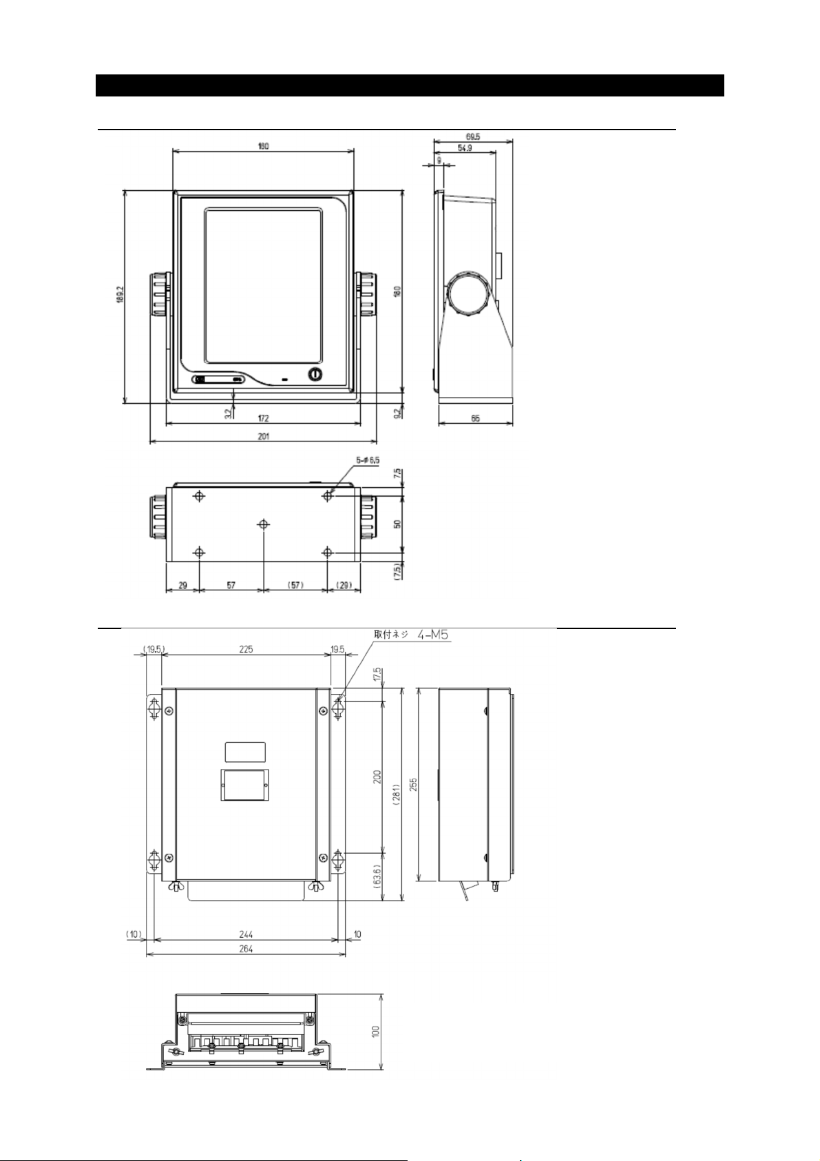
1.4 Construction
NWZ-1650 Display Unit
NDC-4100 Processor Unit
1-4
Unit: mm
Mass: Approximately 2kg
Color: Munsell N2.5
IP Grade: IP56
Unit: mm
Mass: Approximately 2.2kg
Color: Munsell N2.5
IP Grade: IP22
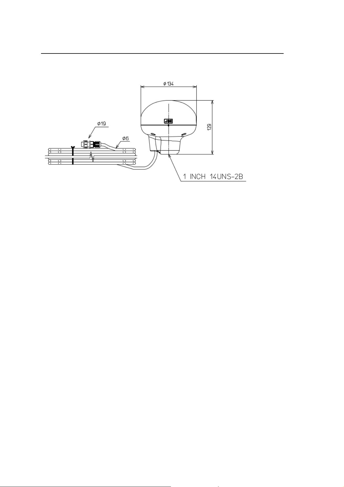
JLR-4350 GPS Sensor Unit
Unit: mm
Mass: Approximately 1.5kg (include 15m cable)
Color: Munsell N9
IP Grade: IP56 (IEC60945)
1-5
NBD-904 Power Supply
Unit: mm
Mass:Approximately 2.6 kg
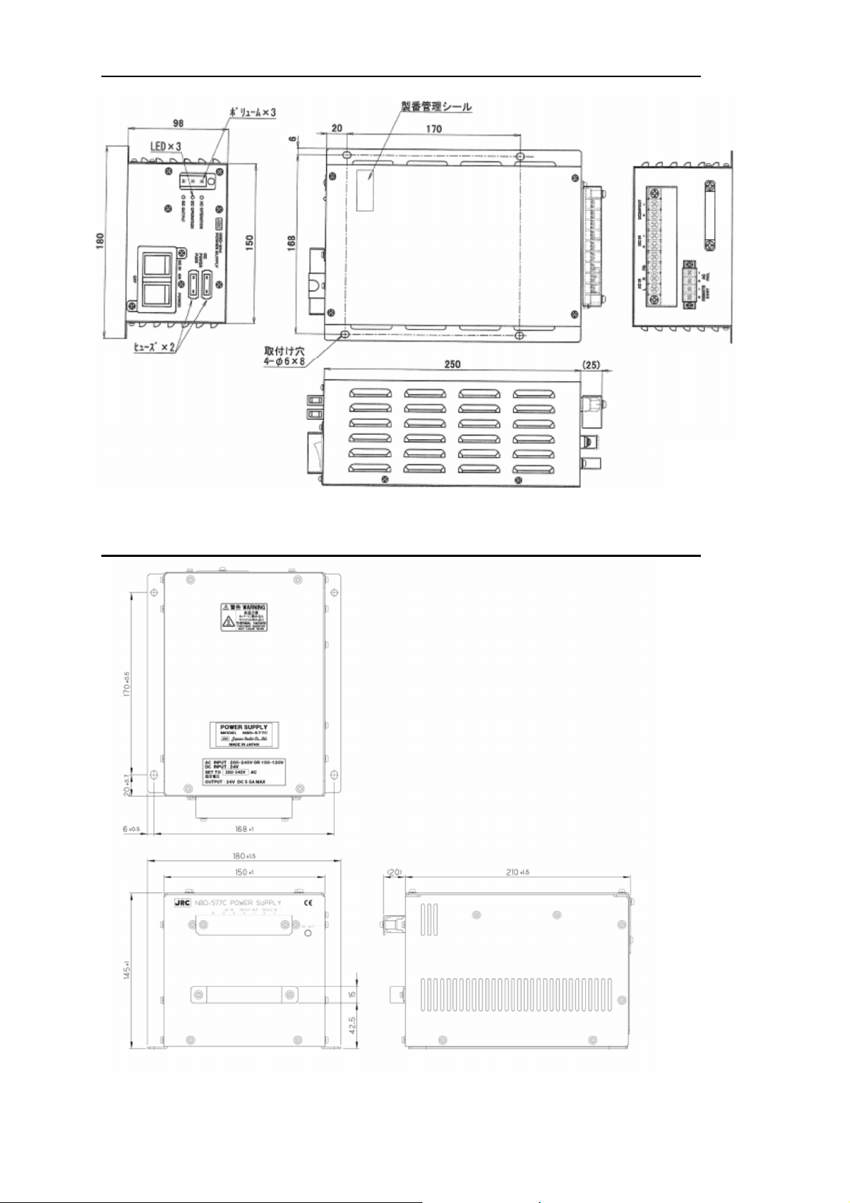
NBD-577C Power Supply
Unit: mm
Mass: Approximately 5.4 kg
1-6
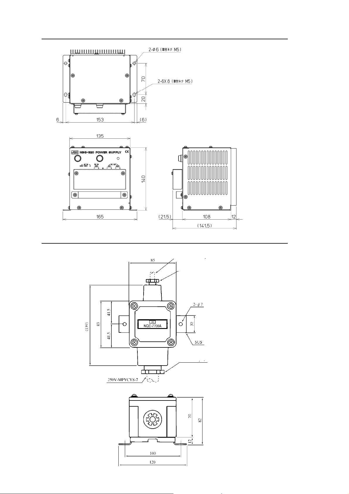
NBG-320 Power Supply
Unit: mm
Mass: Approximately 3.5 kg
NQE-7700A Junction Box
GPS cable
Glandφ15
Unit: mm
Mass: Approximately 0.6 kg
1-7
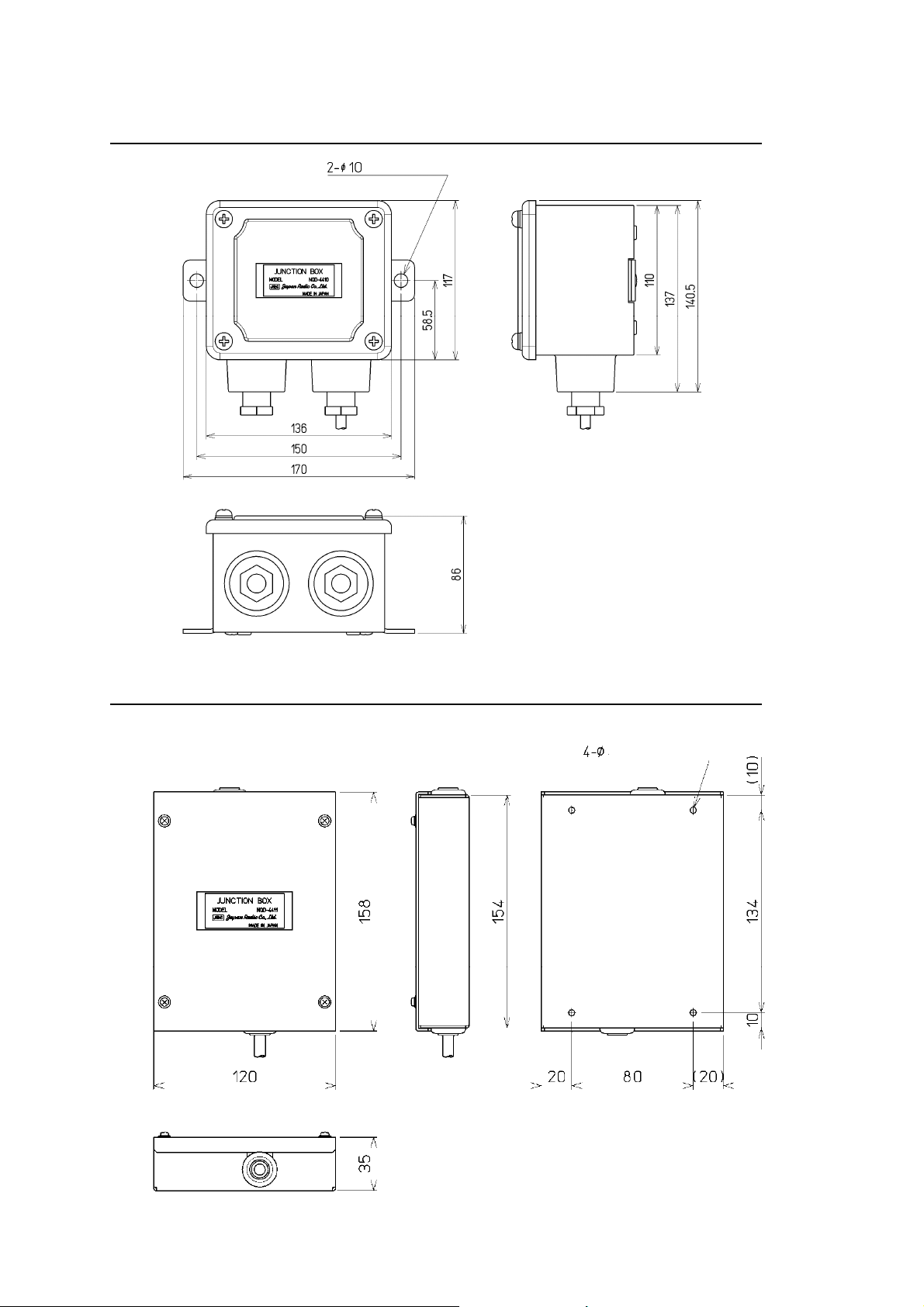
NQD-4414 Coaxial Cable Kit (NQD-4410)
Unit: mm
Mass: Approximately 1.5 kg
NQD-4414 Coaxial Cable Kit (NQD-4411)
(Screw M3)
Unit: mm
Mass: Approximately 0.7 kg
1-8
g
NQA-4351A Output Buffer
Select si
DC Input Data Output
(IEC61162-1 or NMEA) (IEC61162-1 or NMEA)
nal
JUMPER SETTING for DC Input
DC Input JUMPER Terminal
DC 12V TB1-IN
DC 24V TB1-IN
1
2 JUMPER ON 9-16V
JUMPER Cable 0.25~2.5mm
1
2 JUMPER ON 9-16V
Not connect
3
Data Output Data Output
(IEC61162-1 or NMEA) (IEC61162-1 or NMEA)
Unit: mm
Mass: 0.8 kg
1-9
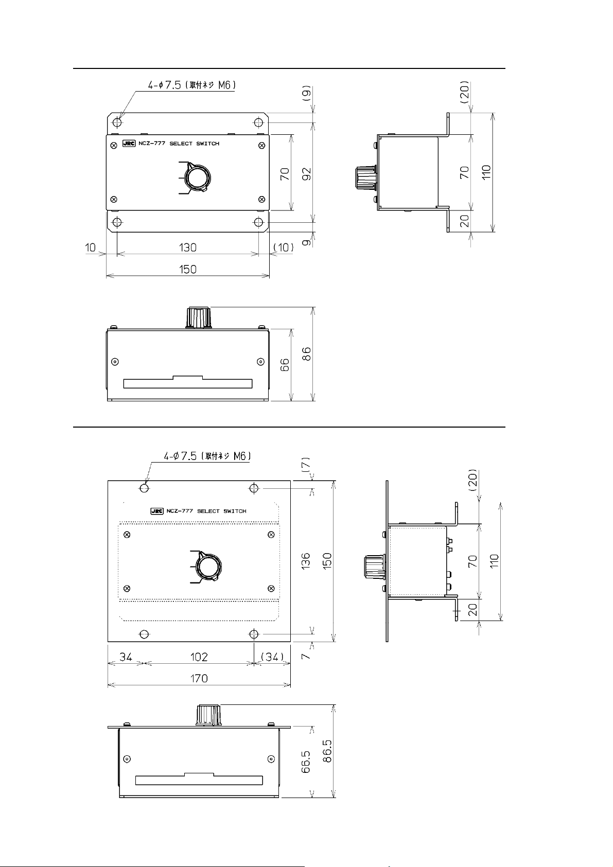
NCZ-777 Select Switch
Unit: mm
Mass: Approximately 0.5 kg
NCZ-777 Select Switch (Flush Mounting)
Unit: mm
Mass: Approximately 0.7 kg
1-10
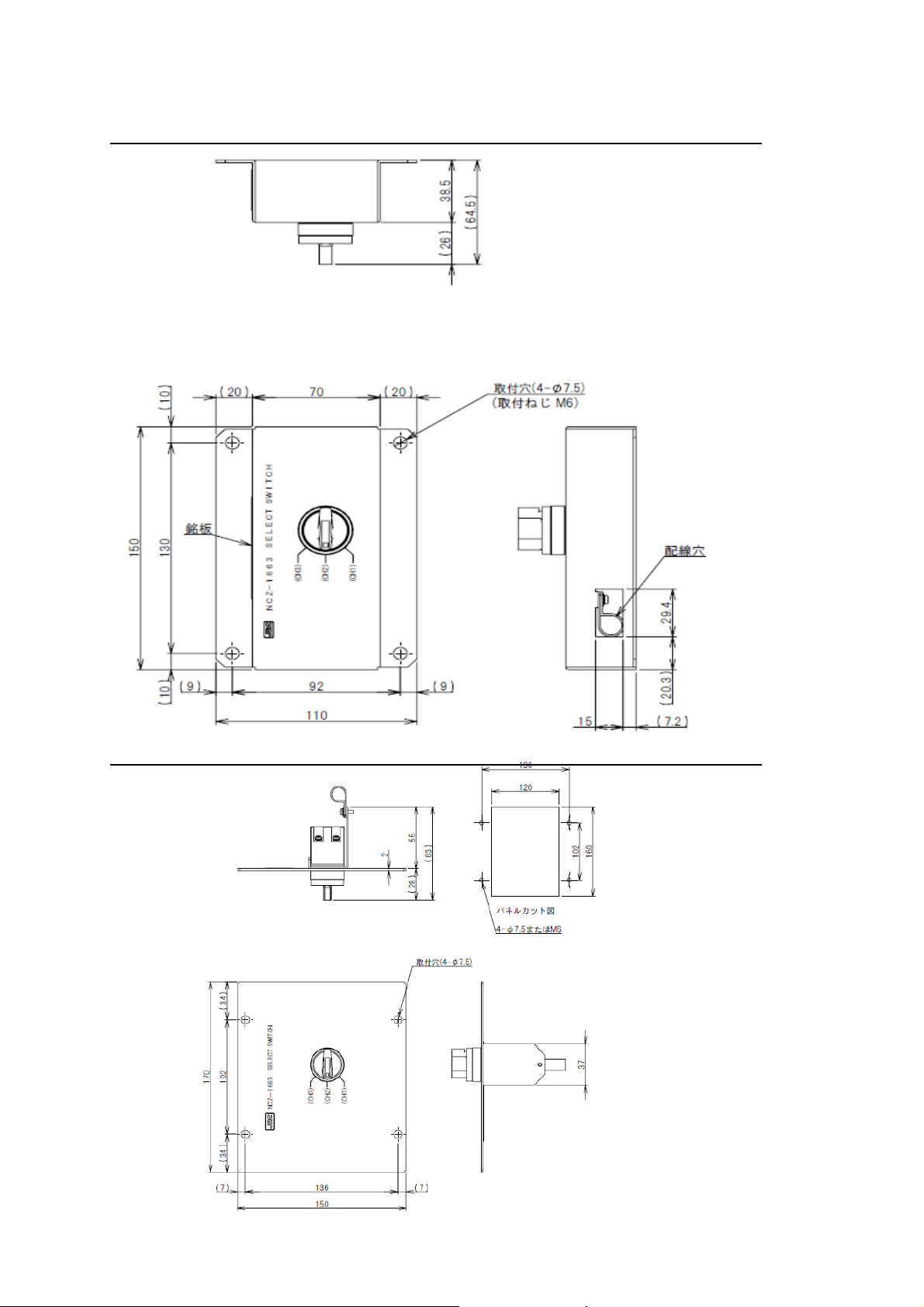
NCZ-1663 Select Switch
Unit: mm
Mass: 0.2 kg
NCZ-1663 Select Switch (Flush Mounting)
1-11
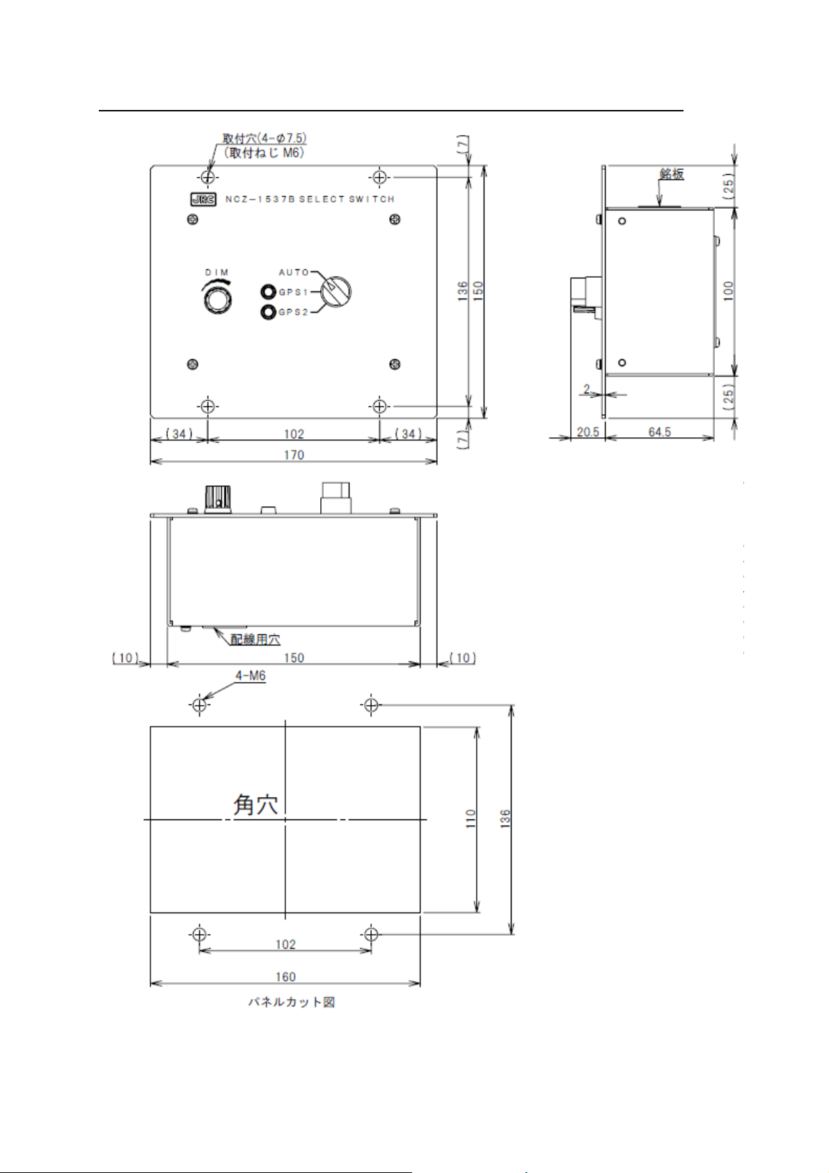
NCZ-1537A/B Select Switch (Flush Mounting)
Unit: mm
Mass: 0.2 kg
Unit: mm
Mass: 0.55 kg
1-12
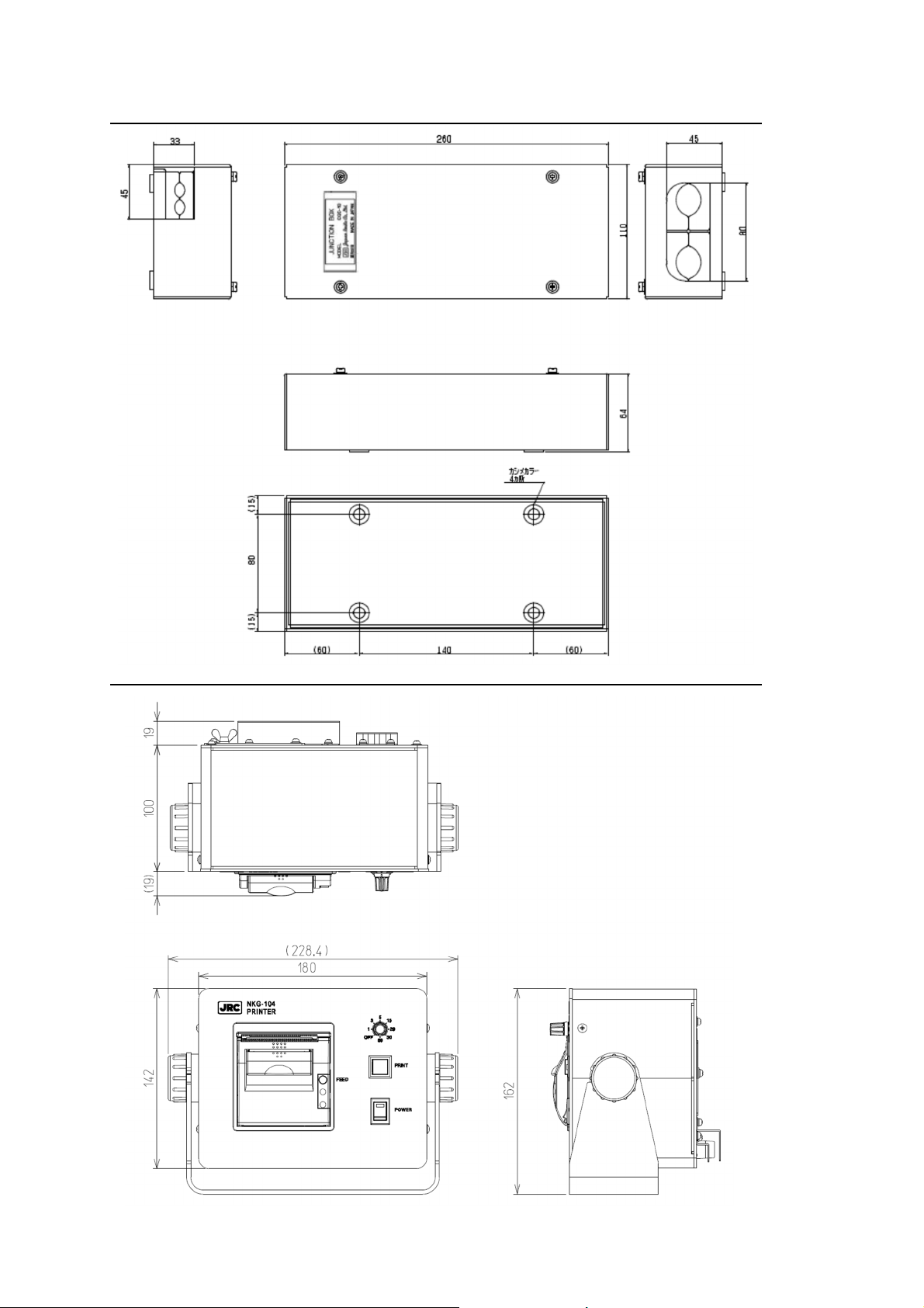
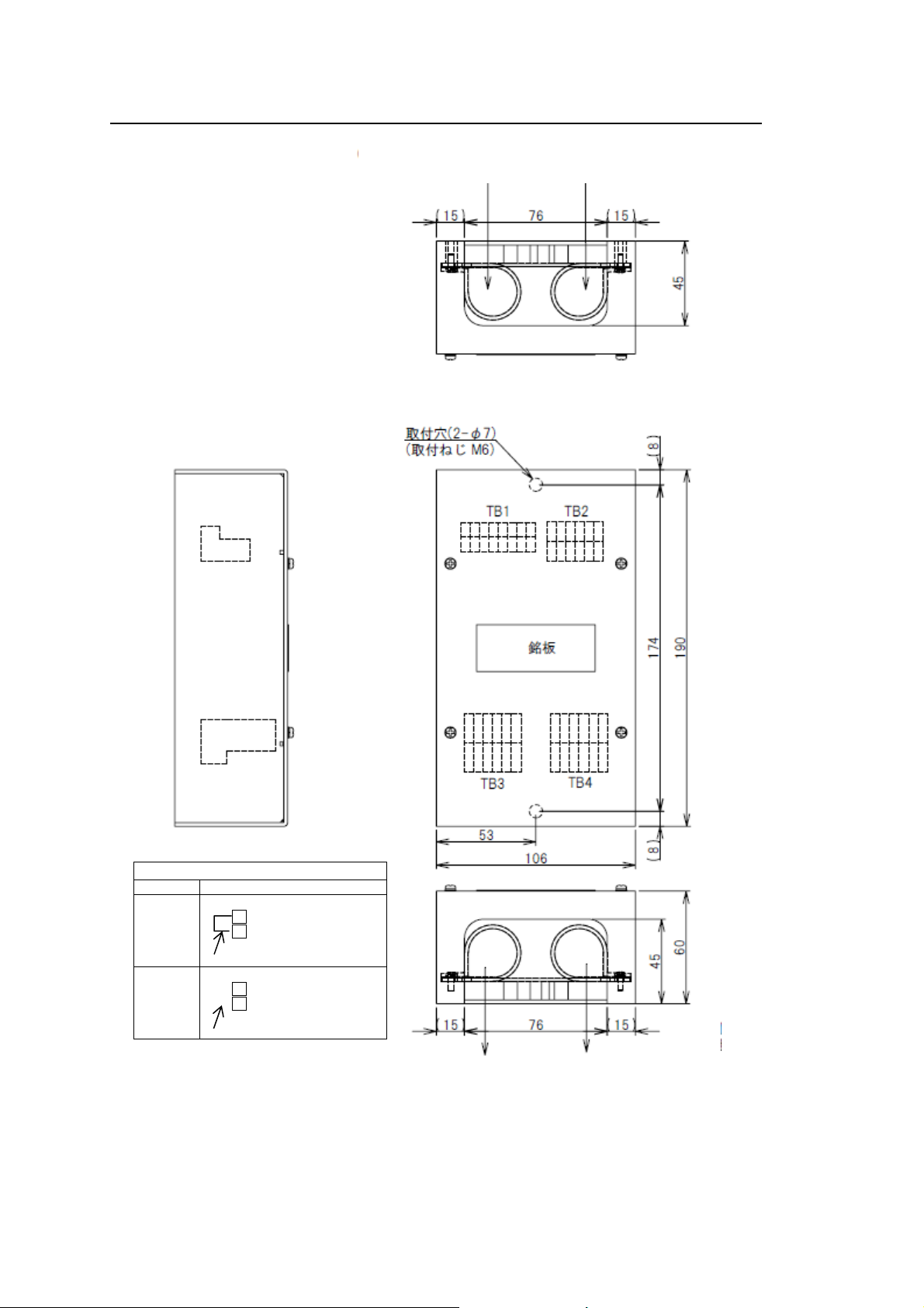
CQD-10 Junction Box
Unit: mm
Mass: Approximately 1.1 kg
NKG-104 Printer
Unit: mm
Mass: Approximately 2.1 kg
1-13
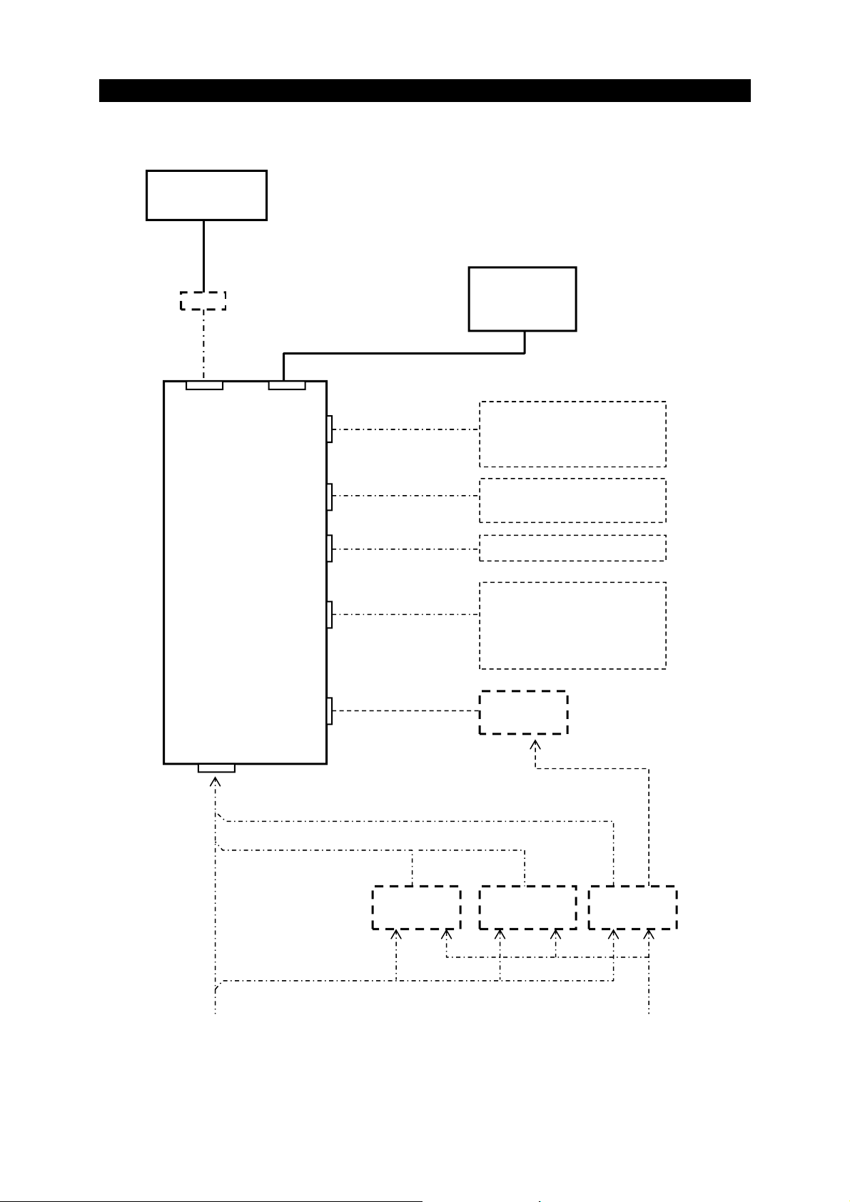
1.5 System Diagram
JLR-4350
GPS Sensor
NQE-7700A Junction Box
250V-MPYCYS-7
Sensor Display Unit
LAN
RS-422
NDC-4100
Processor Unit
Contact
RS-422
(Internal Buffer)
RS-232C
Power Supply
0.6/1kV-DPYC-1.5
DC24V
DC12/24V
DC24V
LAN
CFQ-7540
Ethernet×2
250V-TTYCS-1
IN×2 OUT×5
250V-TTYCS-1
IN×1 OUT×4
250V-TTYCS-1
OUT×8
7CNA4109 or
7ZCNA4112
DC12V
NBD-904
PowerSupply
NWZ-1650
Display Unit
ECDIS
Remote Maintenance
MFD
External equipment
Alarm System
Radar
ECDIS/Plotter
Tide Current Calculator
Printer NKG-104
DPU-414
Printer
7ZCJD0257B
NBD-577C
PowerSupply
NBG-320
PowerSupply
AC110/22012/24V
1-14
y
Chapter 2
Name and Function of Each Unit
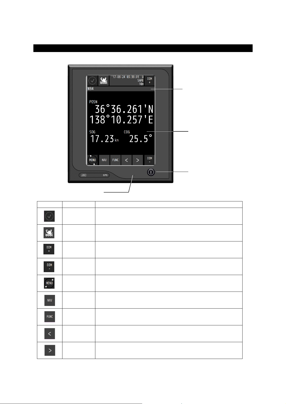
2.1 NWZ-1650 DISPLAY UNIT
Touch panel
Key Name Function
Alert Displays the icon when an alert is issued.
MOB Displays a plotting screen and stores the Man OverBoard position.
DIM UP Increases the brightness.
DIM DOWN Reduces the brightness.
Menu Displays a menu.
Screen Switches a main screen. Select from a main screen list.
Function Displays the operation menu on the main screen.
Screen
switch
Screen
switch
Buzzer
The icon changes according to the alert state.
Displays a freeze indicator.
Switches to a sub screen.
Switches to a sub screen.
Status area
Displays the status of the
equipment or system with
the icon.
DISPLAY
Displays the information of
own ship and equipment
setting screen.
Operated by the touch panel.
Power suppl
key
2-1
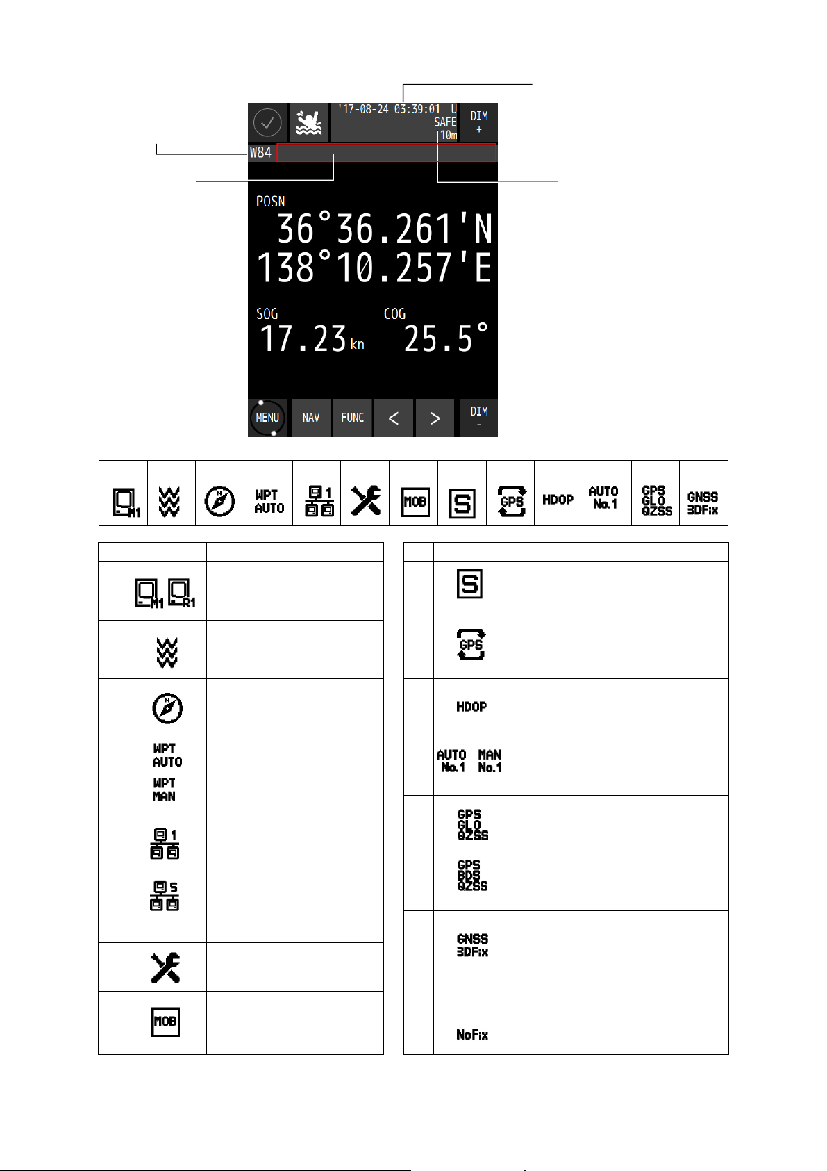
How to read the information on the display
Geodetic
positioning system
Date and time display (note1
U: UTC
L: Local
In the 12-hour display, AM/PM
is displayed.
Status
See the status list
for the contents of
the status.
RAIM
Displays the currently set
accuracy level.
RAIM operating: 10m, 30m,
50m,100m
RAIM OFF:OFF
No faulty satellite: SAFE
RAIM disabled: CAUTION
Faulty satellite: UNSAFE
note1
Although the displayed time may
be out of sync with other display
devices, it is because the data
output timing is different and it is
not a malfunction.
Status list
1 2 3 4 5 6 7 8 9 10 11 12 13
No Icon Description No Icon Description
1
2
3
4
5
6
7 MOB
Display unit number
M: Main display unit
R: Remote display unit
Received beacon
information.
Displayed when beacon
information is received.
Magnetic correction
Displayed when magnetic
correction is set.
Waypoint update state
Displays the waypoint update
mode during route execution.
AUTO: Automatic
MAN: Manual
Route sharing
Displayed when an Active
route is shared.
1: Share 1, 2: Share 2,
3: Share 3, 4: Share 4,
5: Share 5
Installation mode
Displayed in the installation
setting mode.
Displays when MOB is active.
8
9
10
11
12
13
Demo mode
Displayed in demo mode.
DGPS switched.
Indicates that the mode has just
changed from GPS to DGPS.
This icon is cleared automatically
five minutes after the switch.
HDOP alert
Displayed when the value exceeded
the setting value.
Sensor number using display
AUTO: A sensor is selected
automatically.
MAN: A sensor is selected manually.
Positioning system
Indicates the currently set
positioning system.
The positioning system that is set
but cannot be used is displayed in
yellow.
GPS: GPS GLO: GLONASS
QZSS: QZSS BDS: BeiDou
Position fixing status
GNSS: GNSS position fixing
GPS: GPS position fixing
DGPS: Beacon DGPS position fixing
SBAS: SBAS position fixing
2D: 2 dimensional position fixing
3D: 3 dimensional position fixing
No Fix: Non position fixing
2-2
 Loading...