

Page 1
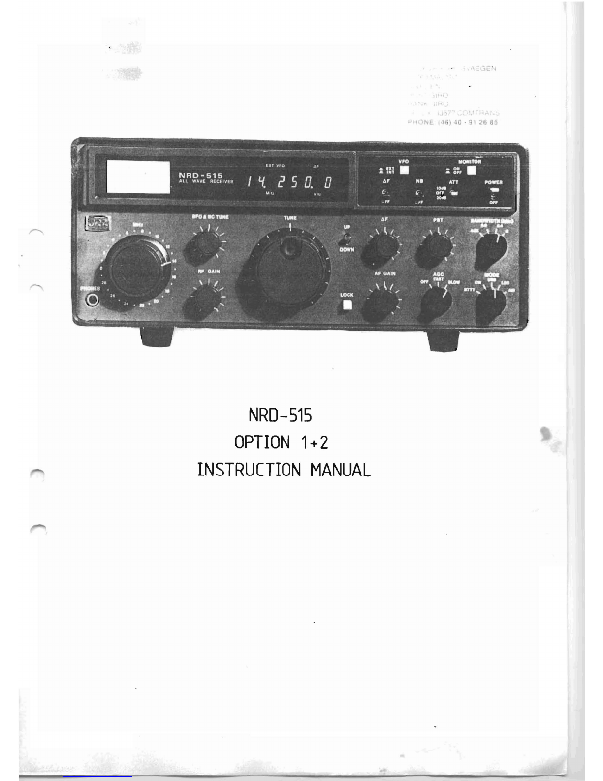
NRD-515
OPTION
1+2
INSTRUCTION
MANUAL
Page 2
List
of
con
tents
Installation
and
adjustment
procedures
page
1+2
User's
manual
page
3+4
Option
l ,
circuit
diagram,
dwg
004-PCB-300-A-8409
page
5
option
l ,
component
location,
dwg
002-PCB-300-A-8409
page
6
Option
2,
circuit
diagram,
dwg
004-PCB-301-A-8409
page
7
Option
2 ,
component
location,
dwg
002-ptB-301-A-8409
page
8
Option
1+2,mechanical
installation,
dwg
003-NRD-OOI-A-8409
page
9
Option
2,
electrical
installation,
dwg
003-PCB-301-A-8409
page
10
Option
2 ,
electrical
installation,
dwg
003-NRD-002-A-8409
page
11
Option
7.
,
wiring
diagram,
dwg
003-NRD-003-A-8409
page
12
Page 3
l
PaS2
Nate:
Tnfa
an
page
2
Nate:
Inf
an
Page
2
Nate:
Infa
an
Page
2
l)
2 )
3 )
4)
5)
6)
7)
8)
9)
10)
l)
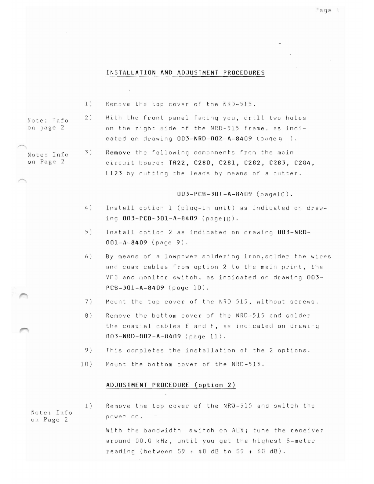
INSTALLATION
AND
ADJUSTMENT
PROCEDURES
Remove
the
top
cover
of
the
NRD-515.
With
the
Front
panel
facing
you,
drill
two
hales
on
the
right
ide
of
the
NRD-515
frame,
as
indi-
cated
on
drawing
003-NRD-002-A-8409
(paqe
9
).
Remove
the
following
compnnents
from
the
mein
circuit
board:
TR22,
C280,
C281,
C282,
C283,
C284,
L123
by
cutting
the
leads
by
means
oF a
cutter.
003-PCB-301-A-8409
(pagelO)
.
lnstall
option
l
(plug-in
unit)
as
indicated
on
draw-
ing
003-PCB-301-A-8409
(pageiO).
Install
option
2
as
indicated
on
drawing
003-NRD-
001-A-8409
(page
9).
By
means
of
a
lowpower
soldering
iron,solder
the
wires
and
coax
cables
from
option
2
to
the
main
print,
the
VFO
and
monitor
switch,
as
indicated
on
drawing
003-
PCB-301-A-8409
(page
10).
Mount
the
top
cover
of
the
NRD-515,
without
screws.
Remove
the
bottom
cover
of
the
NRD-515
and
solder
the
coaxial
cables
E
and
F,
as
indicated
on
drawing
003-NRD-002-A-8409
(page
Il).
This
completes
the
installation
of
the
2
options.
Mount
the
bottom
cover
of
the
NRD-515.
ADJUSTMENT
PROCEDURE
(option
2)
Remove
the
top
cover
of
the
NRO-515
and
switch
the
power
on.
With
the
bandwidth
switch
on
AUX;
tune
the
receiver
around
00.0
kHz,
until
you
get
the
highest
S-meter
reading
(between
59 + 40
dB
to
59 + 60
dB).
Page 4
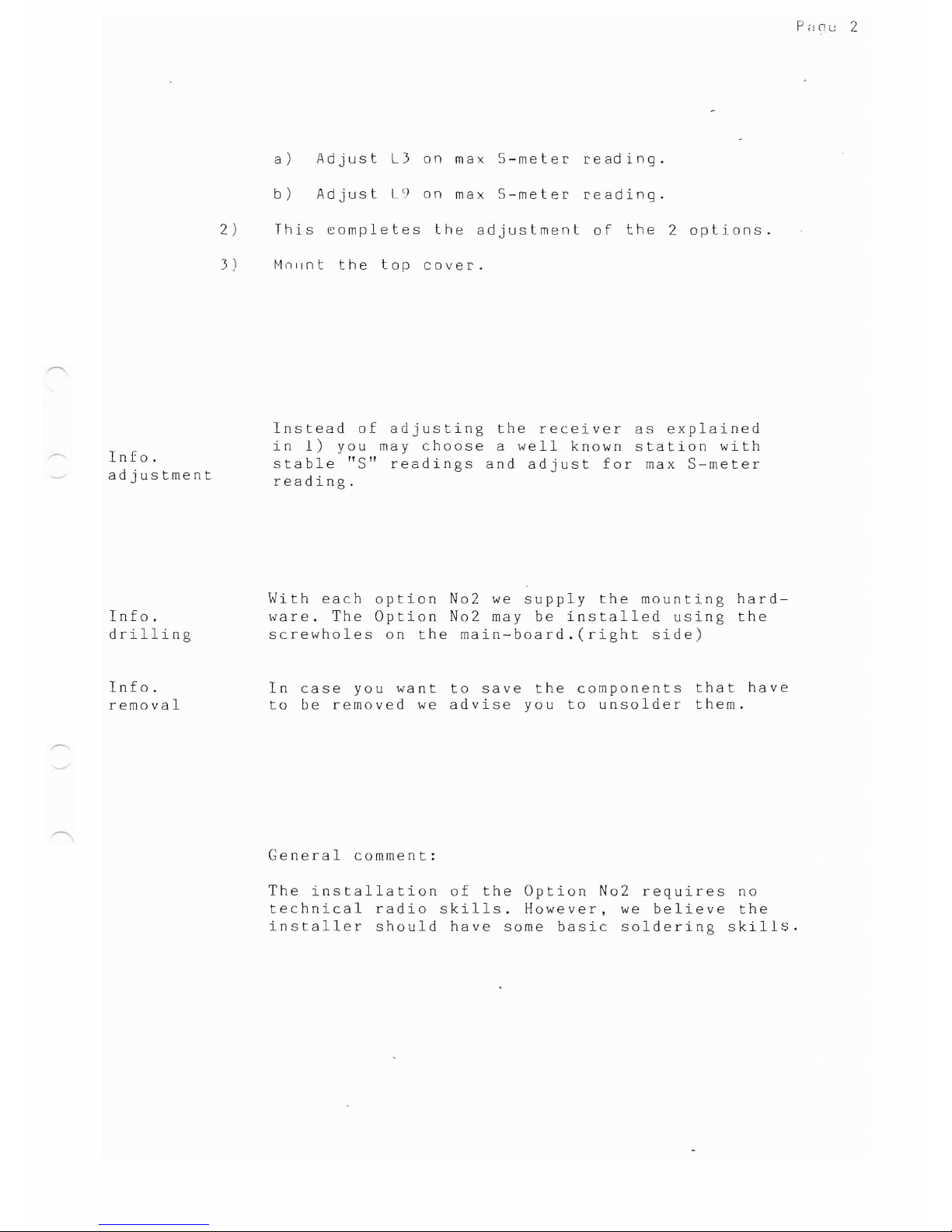
a)
Adjust
L3
on
max
S-meter
reading.
b)
Adjust
L9
on
max
S-meter
reading.
2)
This
~ompletes
the
adjustment
of
the
2
optjons.
3)
Milllnt
the
top
cover.
Instead
of
adjusting
the
receiver
as
explained
in
l)
you
may
choose
a
weIl
known
station
with
Info.
stable
"S"
readings
and
adjust
for
max
S-meter
adjustment
reading.
With
each
option
N02 we
supply
the
mounting
hard-
Info.
ware.
The
Option
N02 may
be
installed
using
the
drilling
screwholes
on
the
main-board.(right
side)
Info.
In
case
you
want
to
save
the
components
that
have
removal
to
be
removed
we
advise
you
to
unsolder
them.
General
comment:
The
installation
of
the
Option
N02
requires
no
technical
radio
skills.
However,
we
believe
the
installer
should
have
same
basic
saldering
skill~.
Page 5
Page
'
U 5 E R
'5
M A N U A L
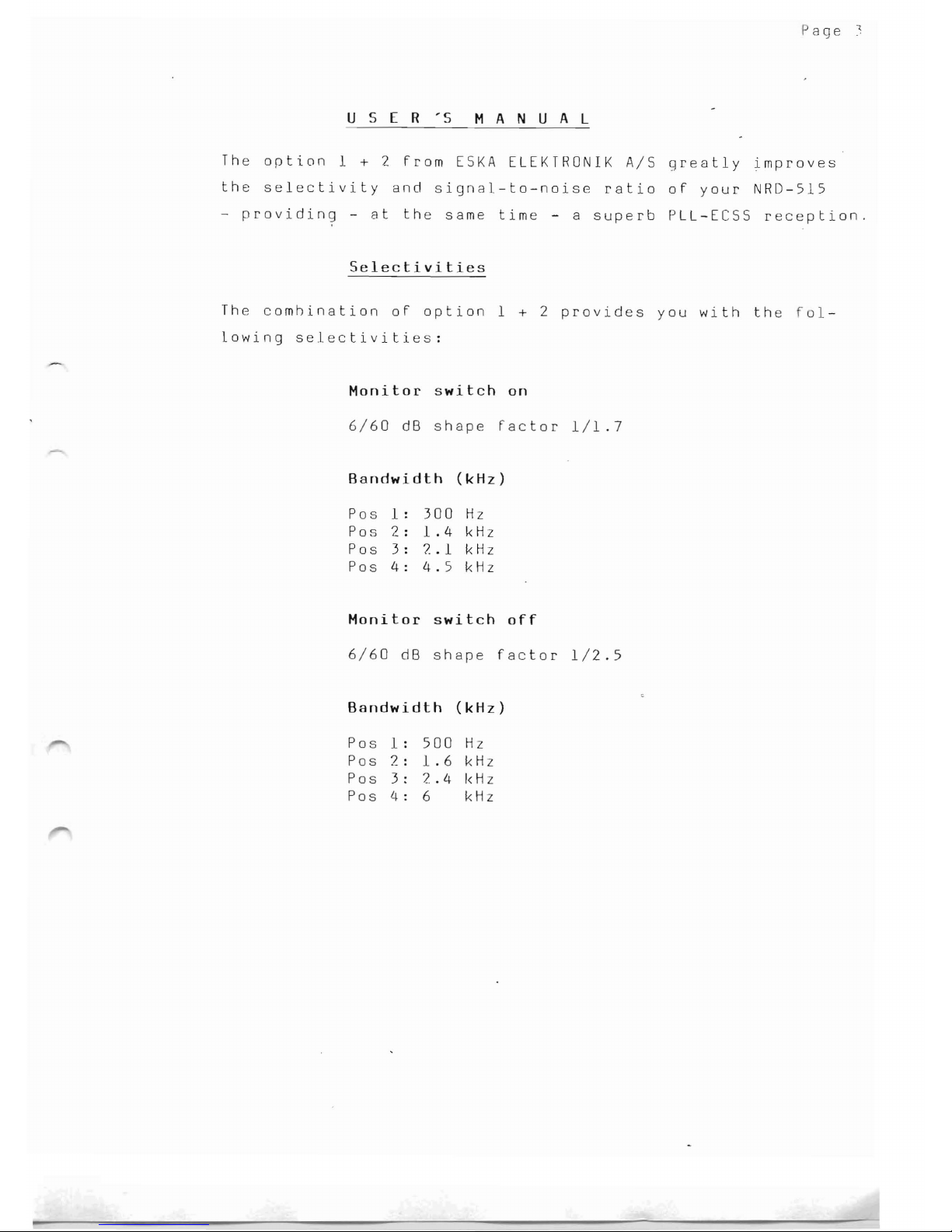
The
option
l + 2
from
ESKA
ELEKTRONIK
A/S
greatly
improves
the
selectivity
and
signal-to-noise
ratio
of
your
NRD-515
-
providing
-
at
the
same
time
- a
superb
PLL-ECSS
reception.
Selectivities
The
comhination
of
option
l + 2
provides
you
with
the
fol-
lowing
selectivities:
Monitor
switch
on
6/60
dB
shape
factor
1/1.7
Bandwidth
(kHz)
Pos
l:
300
Hz
Pos
2:
1.4
kHz
Pos
3:
7..1
kHz
Pos
4:
4.5
kHz
Monitor
switch
off
6/60
dB
shape
factor
1/2.5
Bandwidth
(kHz)
Pos
l :
500
Hz
Pos
2:
1.6
kHz
Pos
3 :
2.4
I<Hz
Pos
4 :
6
kHz
Page 6

he
P L A M
tuning
procedure
The
option
2
jncol'por8t('~;
8
I'IM'l
(letector
to
be
useeJ
~Ih
n
the
received
broar!r.;lstinq
station
'(Jf'rf~rs
From
sel
cti\
F8i1inq.
l n
(j
I'
eJ
o r t o
tt
J
Il
C i n
[I
~j
tilt j
()
fl
'j
n t
h"
P l. !\tvl mu d
e,
p r o e e d
very
cRreFulJy
as
Folluws:
a)
Switrh
6 F
in
on
posltion.
b)
Modt'
swi
tell
on
I
'in
or
USB
dependjn(~
on
illtcr-
FerenCt'.
c ) S
f'
l e c t 6 k Il z ,
or
2.
4 k Hz b n d
"'I
i d t
h,
de p f
~
rl
rl(
Il
g
on
jnterference,
the
monitor
switch
can
either
be
N
o r OF
F,
al
s o d e p
(~n
d i ng o n t he i n t e r Fe r e nc e J e \ e l .
d)
Tune
in
carefully
the
eJesired
frequency
and
a
just
very
slowly
the
6.
Fcontrol
until
the
PLAM
LED
(external
VFO)
lights
up.
Please
nate
that
the
LED
(external
VFO)
always
will
light
up
if
the
carrier
is
not
present
or
iF
you
are
too
far
away
From
the
center
frequency.
e)
Slowly
turn
the
PBT
control
in
order
to
obtain
.he
best
reception
with
the
highest
intelligibilit>
f)
In
ca~e
you
re0erse
sieJeband,
please
repeat
the
procedure
as
indicated
under
step
d
and
e.
Following
fig.
explains
how
the
PLAM
works.
CARRIER
OF
AM
STATION
LOCKRANGE
(,
LED
ON)
LED
ON
LEO
ON
LEO
OFF
LED
OFF
(NO
LOCK)
(NO
LOCK)
(NO
LOCK)
(NO
LOCK)
300
250
200
150
100
50
o
50
100
150
200 250
300
-
HZ
..
4II.-----------t----------t.~
+
HZ
Page 7

-
- -
- -
-
-
- -
-
- - -
-
-
t"'sg
)
L1
82
L4
83
330
)JH
B4
B5
B6
- -
-
81
r--------I
B10
FL1
MF455 -03AZ1
89
(
YF455 -M500)
GI
~
ALTERNATivE
FL2
L5
CFJ455
K8
B8
O-
C>
N
N
I
r-
E
-..J
N
..-
~
B7
AlS
ESKA
ELEKTRONIK
NRD-
515
OPTION
1
004-PCB-300 -A -8409
Page 8

) )
I
or-
U
O
80
~O
I
FL1
I
N
U
O
O~
Ol2
I
l
L3
~~I
L4 00
ll')
L7
U
FL2
L6
I~~
<.D
Oo LS
U L8
-+-
,1)
A/S
ESKA
ELEKTRONIK
iJ
(j)
002
-PCB-300-Ä-8409
':';'"
NRO
-
515
OPTION
1
v
Page 9

--
- - - - - - - - - - - - - - - - - - - - - - - -
--
-
--
- - - - -
~w
.15.,,1
81
-
I
~l
o
r
)
..
sv
fP'
G - I
f p
18
--"-f-+--<)iH I
~
I
O,
BCS<l
J,~
I
l
m
~
I
I
I
I
I
I
I
51
I
I
:3i'g
1P2
•
lIV
I
•
OH
L/~
~_+------=~
---l
f
j l
I
··fN
§
{
l1j
TPS
lS
l8
.sI
U~
12mH
I
~
~
l
ryy
0
"""
{
BI
~
I
RI\160
AJ\]
flO
Rl'.;)
(f
I I
)----
- -
--
'I~'~
ljrP~
C~l
'Dn
~
I
~
,li.
fPb I
I
'-vfO
Wll(F
~I~
r-+U+-
L
I
I
I
L _
~'1
.,
~
~
J.2
a.C>t-1
"
~
5I
[J1r,cn
~y;
~
~
8 'K1
BI
IOP;lClI I
l'
12r:'lri
if
"::.L
I
I
I
I
I
I
I
I
I
I
I
I
I
I
I
I
I
I
I
I
I
I
I
I
I
I
I
I
I
I
I
I
I
°0
~.~
"\V
P:
Ilot1
~
I
'"'C'
I
::J
I l
::J
L____________
~
IJ
-J
t
'>K
fl
NI/Il ',I',
U'
IIUN
}
001,
I'CB·)01-fl-(lI.09
------,
~
~
4<1
~
~
~
c
o
~
'K1
'i)
:'(
if.
8i
8I
BI
Fl.2
Cf1'»<b
~
El
•
~OK
~
I
~t
~
~
f
I
019
iNl.li.S
f
{
Fl'
[WISI
~
!<
o
'Kl
C,_
er
.1';V
~l
g
':1"'"
Jti
"
-----
I
c
_
~~"
·lW
lP'
•
I
D[,
JCr.B~I'n
! H
',"[l
§
Page 10

--
8
I7JO
8JO
ll:l
-o
Par;
-!-
t
c··
c
~
I
<
I
::.:::
z
o
o::
f--
""'
z
::.:::
o
LLJ
-J
LLJ
6
<:t:
::.:::
J)
Vl
.-.:;
LLJ
I
V1
::::J
<:t:
Z
Page 11

174mm
24mm
(il
3,Smm
---+
E
E
r--
~
-
'----
.,-
z
·B
~
lP
Q
O
COMPONENT
SIDE
I
OPTION
2.
Fl
n
J;l
I
II
1111
.....
!
RIGHT
SIDE
OF
THE
RECEIVER
WI
TH THE
FRONT
PANEL
FACING
YOU
AlS
ESKA
ELEKTRONIK
003
-NRD -001-A-8409
NRD -515
Page 12

)REO
{SLEEVE
l
YELLOW
ISLEEVE
I
WHITE
ISLEEVE}
/'If
I
•
,01
61'
K
(-1
,_)
TR22
~,
r
-<=J
Lo.
J
r
-....,
C281
L_-'
r - I
C282
L_J
r - .., L
123
L-_.J
__
~L
r
~
C283
L -
--
.::
-
~
M
C284
= J
TC9-
H
~
\ORl7l
I I
OPTION
1 WJ
o
R150~B
R251~C
R253~
'R252~A
/
00
00
I g
/
..
~"~
...
-"""
O"
•
1-
THE
OPTION
2
PRINTEO
CIRCUlT
BOARC
IS
SUPPLlED
WITH
ALL
THE
NECESSAk'f
WIRES
AND
CA8LES
READY
FOR
SOLO~~ING
ITH
THE
CORRECT
LENGT
HS
A
YELlaw
l =
250
B
ORANGE
l=
250
C:
RED
L=
250
o:
BROWN
l =
250
K
BLUE
L=
80
O:
ORANGE
L=
180
p.
GREY
L=
100
N .!HITE
L=
180
~\
F,)
COAX
L=
700
Gl
Hl
COAX
L=
250
OPTJON
2
~J
COAX
L=
170
2)
COAX
L=
200
N"
I
TOP
SIDE
OF
THE
RECEIVER
I1
h
u
~~
'I
VFO
MONITOR
P
..
II
o .. 'I
REMOVE
:C28~
(281, (282,
C283,
(284,
K'"
'I
Lm,
TR22
003
-PCB
- 301-A-8409
ESKA
ELEKTRONIK
N
1~
D-
515
! J
-:J
;,
'»
D
C)
I
Page 13

I
I
-
-
F
- 7
E
b{
JL
IU8
I I
I I
BOTTOM
VIEW
hnn n
II
I I I I
II
ESKA
ELEKTRONIK
003-NRO
-002-A-8409
NRD-S1S
Page 14

ro
I I
I I
L.::~
o
IC38
R250
o
R171
B
R251~
R253
~l
II
II
I
e,rr
A
Jj
r
R252
.-f:i
....
L
--:..
__
l.~~
"
TP18
~
[j
1
1
g~-
i
IC38
lo
O O I
BOHOM
VIEW
OF
THE
RECEIVER
COAX
E,F
TOP
VIEW
OF
THE
RECEIVER
VFO
MONITOR
ESKA
ELEKTRONIK
003-NRO-003-Ä-8409
l,~
NRD-"i]"i
1--
I
--
I
I;::;
 Loading...