

Page 1
INSTR UCTION MANUAL
GPS NA VIGAT OR
NWZ-4551
MODE
MENU
MOB
DIM
CONT
CLR
PWR
EVENT
GOTO
OFF
OFF
PUSH
GPS NAVIGATOR
Page 2

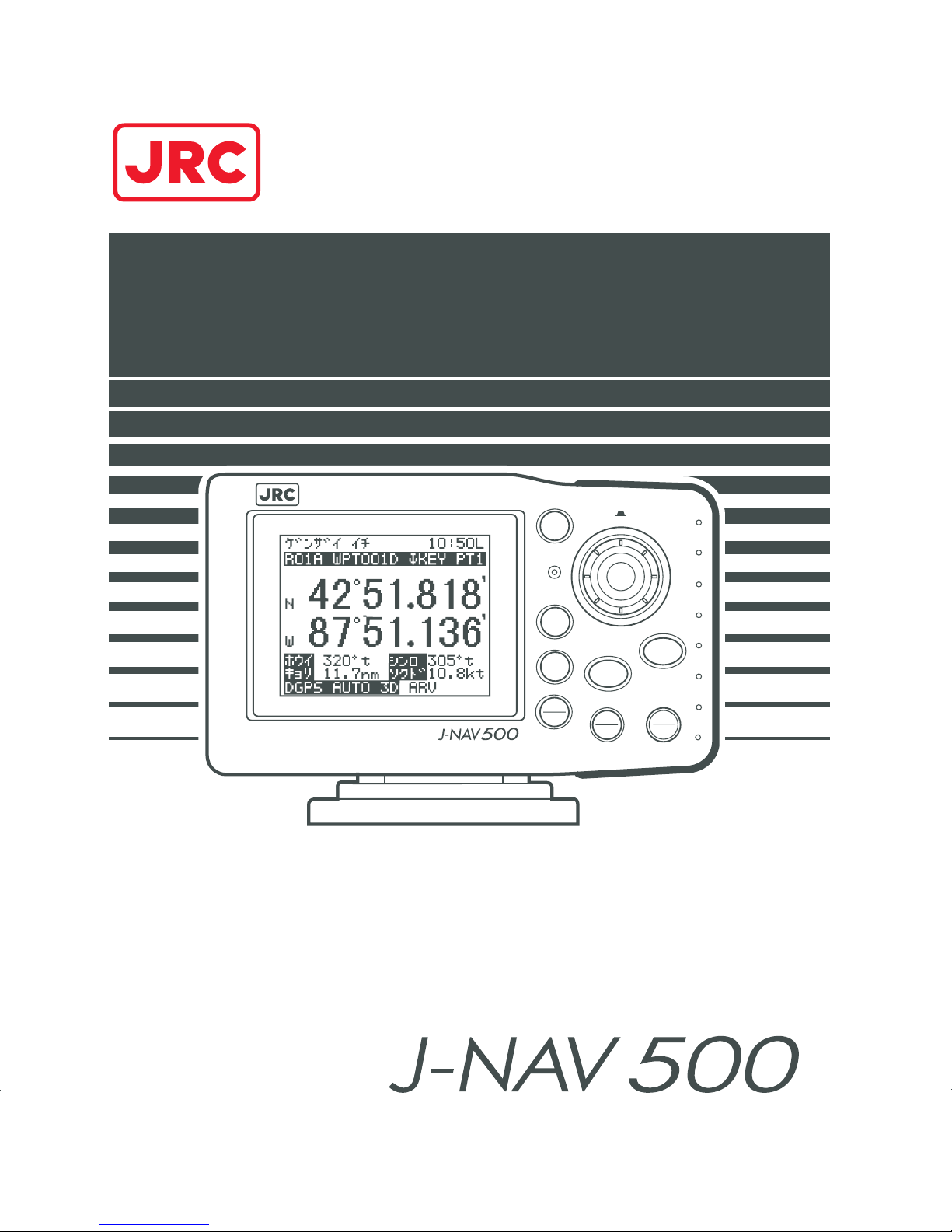
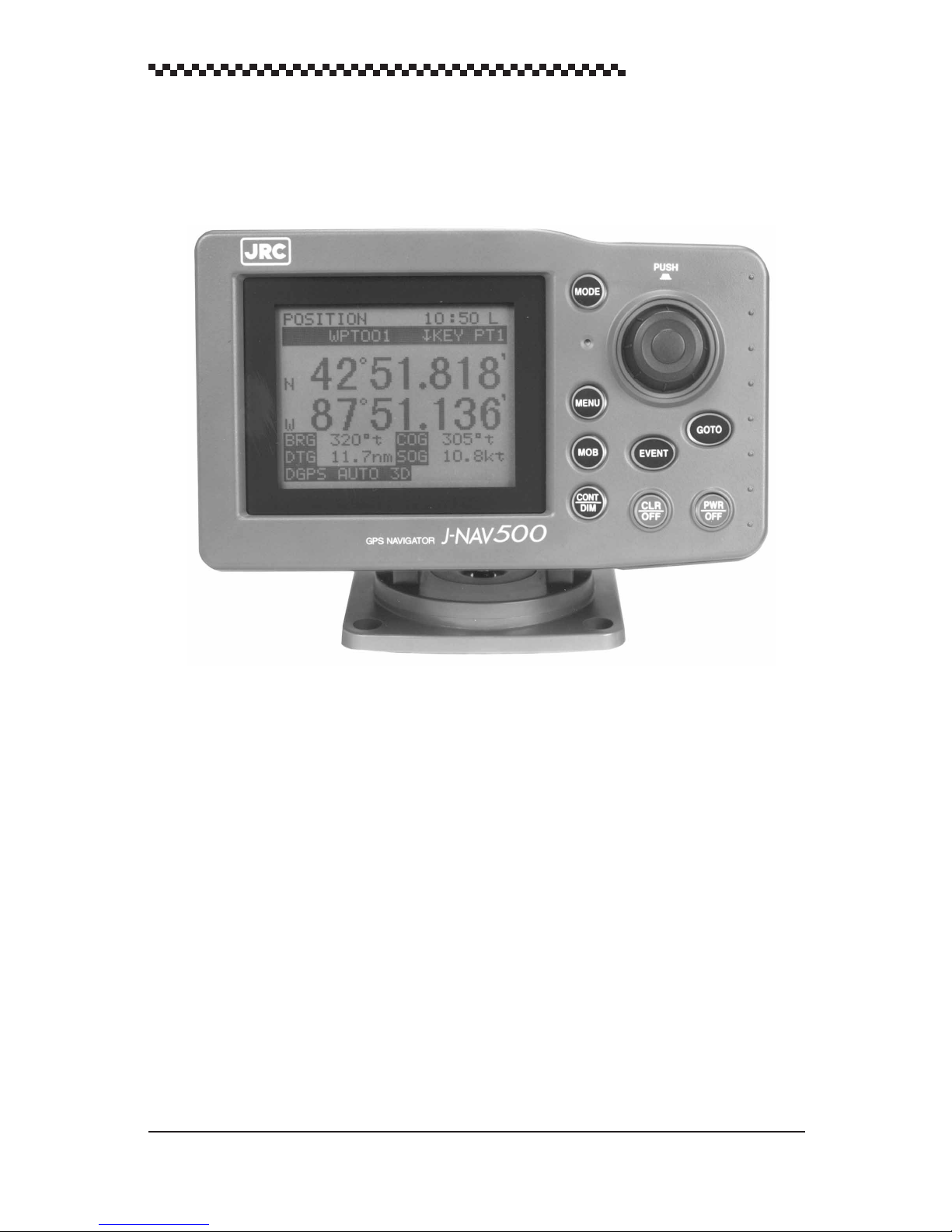
GPS Navigator J-NAV500
General Information
Thank you for purchasing the GPS Navigator J-NAV500. This navigator obtains position data
from a GPS/DGPS receiver and can shows all types of marine navigation displays.
• Before attempting to operate this unit, read this instruction manual thoroughly to correctly and safely
operate this unit in accordance with the warning instructions and operation procedures in this manual.
• Keep this instruction manual in an easily accessible location so that you can refer to it in the event of
a failure or other problem.
1
Page 3
GPS Navigator J-NAV500
Before you begin
Related symbols
In this manual, and on the equipment, there are several labels to call your attention to important items that, if not handled correctly, could present danger to yourself or property. The
labels used and their meaning are described below.
Read through the safety instructions and make sure you fully understand them before you
read the rest of the manual.
WARNING
CAUTION
Symbol examples
Equilateral triangles alert the user to a possible danger (danger or warning) that
may be caused by wrongful operation or misuse of this product.
The symbol inside the triangle graphically represents the actual danger. (The
example on the left warns the user of the danger of electric shock.)
White circles with a 45¡ slash angled downward from upper left to lower right
notifies the user that specific actions are prohibited to prevent possible danger.
The symbol inside the circle is a graphical representation of the actual prohibited
action. (The example on the left notifies the user that disassembly is prohibited.)
Disassembly
prohibited
Dangerous
voltage
Prohibition
Indicates a situation which, if not avoided, could result in
death or serious injury and is extremely likely to cause
minor injury or property damage.
Indicates a situation which, if not avoided or handled
correctly , may result in injury or property damage, but not
likely to lead to serious personal injuries.
Black filled-in circles instruct the user to carry out a specific obligatory action to
Remove plug!
Instruction
prevent possible danger.
The symbol inside the circle is a graphical representation of the actual action to
be carried out. (The example on the left instructs the user to remove the plug from
the outlet.)
2
Page 4
Safety Precautions
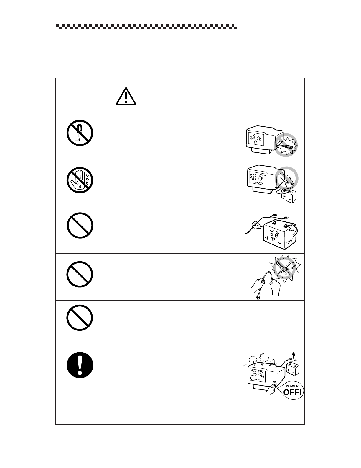
WARNING
Do not disassemble or modify this unit. Otherwise, a fire,
an electrical shock, or a failure may occur.
Do not remove or insert the power cable with wet hands.
Otherwise, you may suffer from an electrical shock.
GPS Navigator J-NAV500
Do not use voltage other than 12 VDC.
Otherwise, a fire, an electrical shock, or a failure may
occur.
Do not fray, damage or modify the power cable. When a
heavy object is placed on the cable or the cable is heated,
pulled, or forcibly bent, the cable will be broken resulting in
a fire or an electrical shock.
Do not operate this unit while you are also steering the vessel as this may lead to an accident.
In the event that smoking or burning odors are detected,
immediately terminate operation of the set and contact
our company , branch, or local of fice. Continuing operation as is may cause a fire or electrical shock. Never
attempt to service the interior of this set.
3
Page 5
GPS Navigator J-NAV500
This unit does not automatically assess position information. It is the user’s responsibility to judge position and navigational information.
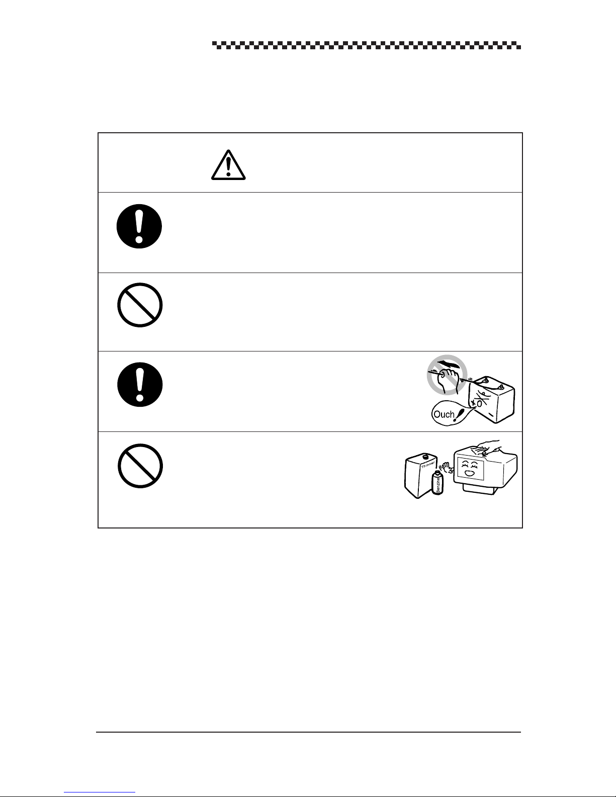
Do not drop this unit into water. When water enters the unit,
a failure may occur.
CAUTION
When removing the power cord, be sure to remove the
power cord terminal correctly . If the power cord is pulled,
the cord may be damaged resulting in a fire or an electrical
shock.
When cleaning the surface, do not use any organic
solvent such as thinner or benzine, Otherwise, the
painting on the surface may be damaged.
For cleaning the surface, remove the dust and grease
with clean dry cloth.
See “List of Offices” on the back cover of this instruction manual for information on addresses and
telephone numbers of sales departments, subsidiaries, branch offices and service centers of Japan Radio
Co., Ltd.
4
Page 6
Outside View
GPS Navigator J-NAV500
5
Page 7

GPS Navigator J-NAV500
Contents
General Information .............................................................................. 1
Before you Begin................................................................................... 2
Safety Precautions ................................................................................ 3
Outside View ......................................................................................... 5
Definition of Terms ................................................................................ 8
1. Overview..................................................................................... 10
1.1 Functions ................................................................................................................ 10
1.2 Features .................................................................................................................. 11
1.3 Equipment supplied................................................................................................ 1 1
1.4 Structure ................................................................................................................. 12
1.5 Equipment connections .......................................................................................... 12
2. Names and Functions of Parts ................................................... 13
2.1 Operation panel ...................................................................................................... 13
2.2 Rear panel............................................................................................................... 15
3. Installation................................................................................... 16
3.1 Display installation................................................................................................. 16
3.1.1 Choosing the location.................................................................................. 17
3.1.2 Mounting the unit ........................................................................................ 17
3.2 Cable connections .................................................................................................. 19
3.2.1 GPS/DGPS receiver connection ................................................................. 19
3.2.2 Power cable connection .............................................................................. 19
3.2.3 Ground connection ...................................................................................... 21
3.3 EMC Installation & service guidelines................................................................... 22
3.3.1 Installation................................................................................................... 22
3.3.2 Check Before Going to Sea......................................................................... 22
3.3.3 Servicing and Safety ................................................................................... 22
4. Operation .................................................................................... 23
4.1 Overview ................................................................................................................ 23
4.2 Turning the unit on/off............................................................................................ 24
4.3 Selecting display language ..................................................................................... 25
4.4 Switching between Main Display Modes ............................................................... 26
4.5 Main Display Modes .............................................................................................. 28
4.5.1 POSITION display mode ............................................................................ 28
4.5.2 NAVIGATION display mode ...................................................................... 32
4.5.3 CDI display mode ....................................................................................... 32
4.5.4 PLOT display mode and setting the plot scale............................................ 33
4.5.5 WAYPOINT display mode.......................................................................... 34
4.5.6 ROUTE display mode ................................................................................. 34
4.5.7 STA TUS/SF display mode .......................................................................... 35
4.6 Basic menu selection operations ............................................................................ 37
6
Page 8

GPS Navigator J-NAV500
4.7 Adjusting Contrast and Backlighting ..................................................................... 39
4.8 Setting Alarms (Arrival/Anchor/Off-course/DGPS) .............................................. 39
4.9 Navigation using direct route (GOTO)................................................................... 41
4.10 Navigation according to route plan ........................................................................ 42
4.11 Entering current position as a waypoint [EVENT] ................................................ 43
4.12 Man-Overboard Mode............................................................................................ 44
4.13 Position Display Mode/Position Correction/Geodetic System Correction/
Magnetic Compass Correction ............................................................................... 44
4.14 Setting Navigation Display Modes and Units ........................................................ 46
4.15 Setting CDI range and Display Time Format ......................................................... 47
4.16 Setting Plotting Information ................................................................................... 47
4.17 Entering W aypoints ................................................................................................ 48
4.17.1 Editing W aypoint Lists................................................................................ 48
4.17.2 Storing waypoints........................................................................................ 50
4.17.3 Erasing, copying and measuring waypoints ................................................ 52
4.17.4 Sorting waypoint list ................................................................................... 54
4.18 Setting Route Plans ................................................................................................ 54
4.18.1 Making a route plan .................................................................................... 55
4.18.2 Editing route plan........................................................................................ 56
4.18.3 Erasing route plans...................................................................................... 57
4.19 Setting GPS information......................................................................................... 58
4.19.1 Setting positioning mode and averaging time ............................................. 58
4.19.2 Initializing GPS/DGPS receiver.................................................................. 59
4.19.3 TD initializing ............................................................................................. 60
4.19.4 Setting DGPS beacon.................................................................................. 61
4.20 Setting Data Output and transmit memory data...................................................... 62
4.21 Displaying the Simulator Mode.............................................................................. 64
4.22 Performing Master Reset........................................................................................ 65
5. Maintenance and Inspection....................................................... 66
6 After-sales Service...................................................................... 67
7. Disposal ...................................................................................... 68
7.1 Disposal of Navigator............................................................................................. 68
7.2 Handling Used Lithium Batteries ........................................................................... 68
8. Specifications.............................................................................. 69
Appendices ......................................................................................... 71
Appendix A Message list .............................................................................................. 71
Appendix B Geodetic system Table.............................................................................. 73
Appendix C NMEA0183 output sentence and data format........................................... 75
Appendix D Waypoint/Route Plan Data In/Output ....................................................... 80
Appendix E Waypoint List ............................................................................................ 81
How to address inquiries List of Offices Back Cover
7
Page 9

GPS Navigator J-NAV500
Definition of Terms
GPS satellite GPS stands for “Global Positioning System.” One of several
satellites launched by the US Department of Defense to establish a military navigational aid system.
DGPS The process of correcting the inaccuracies of GPS position data
from GPS satellites by receiving a beacon receiver (via a beacon station) in a base station whose exact position is known.
Position fixing The process of deriving the current location of a vessel using
GPS or DGPS receiver.
2D (two-dimensional) Position fixing using satellites and height information.
3D (three-dimensional) Position fixing using satellites information only from four or
more satellites
HDOP Indicates the accuracy of position fixing. The smaller the num-
ber shows the more accurate the position fixing.
When the satellites are grouped together, HDOP increases and
position fixing accuracy is poor; when the satellites are far apart,
HDOP decreases and position fixing accuracy is enhanced.
Loran C time difference Information for deriving current position by calculating the time
difference between a master station and secondary station of the
Loran C system. (Information designed for users experienced
in the use of the Loran C navigation system)
TD Time difference. The time difference between a master station
and secondary station of the Loran C system.
Route plan A plan that registers a series of waypoints in a navigational path.
CDI Course Deviation Indicator. Information that indicates the ex-
tent you have strayed from the route of deviation and the direc-
tion to steer.
Arrival alarm An alarm indicating that the vessel has come within the set dis-
tance of a waypoint.
Anchor alarm An alarm indicating that the vessel has deviated more than the
set distance from a waypoint.
Off-course alarm An alarm indicating that the vessel has deviated more than a set
distance from a predetermined course.
8
Page 10

GPS Navigator J-NAV500
Automatic sequencing mode Function that automatically steps from one waypoint to the next
when the arrival perpendicular point has been detected.
Manual sequencing mode The unit sounds the arrival alarm and the operator will manually
press key to step to next leg in the route plan when it is safe to
do so.
Default value Factory set value
NMEA0183 National Marine Electrical Association 0183. Association es-
tablishing international standards for communications between
navigational equipment and the standard established by NMEA.
Master reset A function for clearing all settings and returning to the factory
set values (default values). Two types of master resets are pro-
vided. A soft reset clears all data except for waypoint and route
plan data. A hard reset clears all data.
Initialization It takes up to 20 minutes to GPS position fixing when it is used
for the first time or after a master reset has been performed.
This time can be reduced by entering initialization values such
as estimate position, time and antenna height.
9
Page 11

GPS Navigator J-NAV500
1. Overview
1.1 Functions
Attaching an optional GPS/DGPS receiver (GPS 100 or DGPS 200) makes it possible to turn the GPS
Navigator J-NAV500 into a GPS/DGPS navigational system. This navigational system uses GPS satellites to calculate accurate positions anywhere in the world and under any weather conditions 24 hours
a day. This navigator displays navigational paths to entered waypoints using position data. There are
the following four navigation displays:
• POSITION Displays the latitude and longitude of the current position. It also dis-
plays the bearing and distance to a waypoint, course, speed, etc. and
the Loran C time difference.
• NAVIGATION Displays the bearing and distance to a waypoint, deviation and correct
steering direction to the route, and time to arrival to a destination.
Selections can be made to display the desired information.
• CDI Displays a graphic representation of course deviation. It also displays
correct steering direction, course and speed.
• PLOT Displays a graphic representation of the route line, the tracked line and
waypoints. W aypoints are indicated by symbols or alphabetic characters.
There is also a [STATUS] display showing status information such as satellite number, beacon frequency and receiving level.
A total of 499 waypoints and 20 route plans can be entered in the navigator. A single press of the
key can turn any current location into a waypoint. Someone should fall overboard, press the
key for an instant graphic representation of that position and the route to return to this position.
10
Page 12

GPS Navigator J-NAV500
1.2 Features
This navigator is equipped with the following features.
• Large backlit dot matrix liquid crystal display
The large display makes it easy to view the information provided by the many display modes. The
backlit keyboard keys facilitate night operation.
• Graphic representation
The CDI display mode allows you to get the direction to steer at a glance, supports safe navigation
and saves fuel.
The plot display mode displays the symbols registering the route and each waypoint.
• Menu driven easy operation
The display menus facilitate operation by showing what to do next. Menu selections and data
entry are performed with an easy-to-use dial.
• Customize
The great number of features provided makes it possible to customize functions and build your
own navigation system.
• One-touch removal and installation
The display can easily be removed or installed by pressing the button on the rear panel.
• Support for seven display languages is provided.
1.3 Equipment supplied
The table below lists items that are included with your J-NAV500. If an item is missing, contact your
JRC dealer for assistance.
Item Description Q'ty Remarks
Display unit NWZ-4551 1
Bracket MPBX35850 1 Included with the navigator
Power cable CFQ-8410 1 Length 1.8 m, with a fuse (2 A)
Fuse MF60NR-2A 1 Spare fuse (2A)
T apping screws MPTG30149 1 4 pcs.
Instruction manual DC50-NWZ-4551 1 English
The following optional accessories are also available.
Flush mount kit: MPTG30432
DGPS receiver: DGPS200
GPS receiver: GPS100
24 VDC power supply unit: NBG-121
AC power supply unit: NBG-122
11
Page 13
GPS Navigator J-NAV500
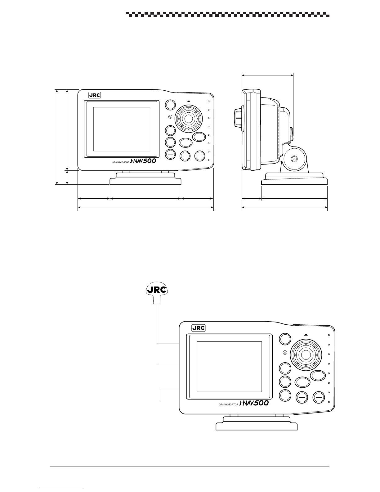
1.4 Structure
The outside view of the display unit is shown below .
74
11721
138
46.5 104
197
1.5 Equipment connections
Equipment connections are shown below .
MOB
PUSH
GOTO
EVENT
CLR
DIM
OFF
MODE
MENU
CONT
46.5
Figure 1-1
PWR
OFF
28 96
124
UNIT : mm
WEIGHT : Less than 0.9kg
GPS/DGPS receiver
(optional GPS 100 or DGPS 200)
12 VDC power/input Data I/O
(Power cable supplied)
To vessel ground
12
Figure 1-2
MODE
MENU
MOB
CONT
DIM
EVENT
CLR
OFF
PUSH
GOTO
PWR
OFF
Page 14
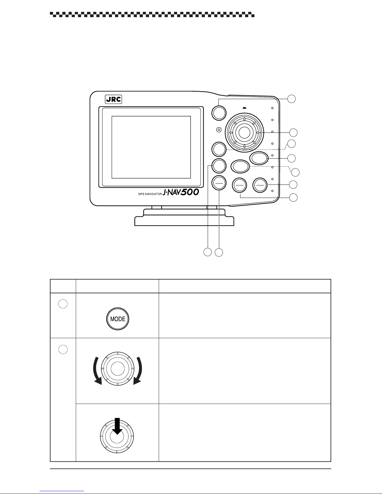
2. Names and Functions of Parts
2.1 Operation panel
The illustration shows the keys on the operation panel and their functions.
GPS Navigator J-NAV500
Figure 2-1
PUSH
MODE
1
2
MENU
MOB
GOTO
EVENT
3
4
5
CONT
DIM
CLR
OFF
PWR
OFF
6
7
9
8
No.
1
2
Name Function
Mode
Dial
Down Up
ENT (Press dial)
• Press this key in mode exept [ MOB ] to select main display mode.
• Press this key in the [ Select Mode ] display to return to previous
display mode.
• Turn to select menu. (Turn dial counterclockwise to scroll downward and turn it clockwise to scroll upward.)
• Selects menu items.
• Sets numeric values when menu items are numeric entry. (The
numbers change faster, when the dial is turned faster.)
• Press the dial to select a menu or to enter a setting.
• When following a route sequence manually, use the dial to step
the next waypoint.
This function is available in the following display modes:
[POSITION]. [NAVIGATION]. [CD] displays
13
Page 15
GPS Navigator J-NAV500
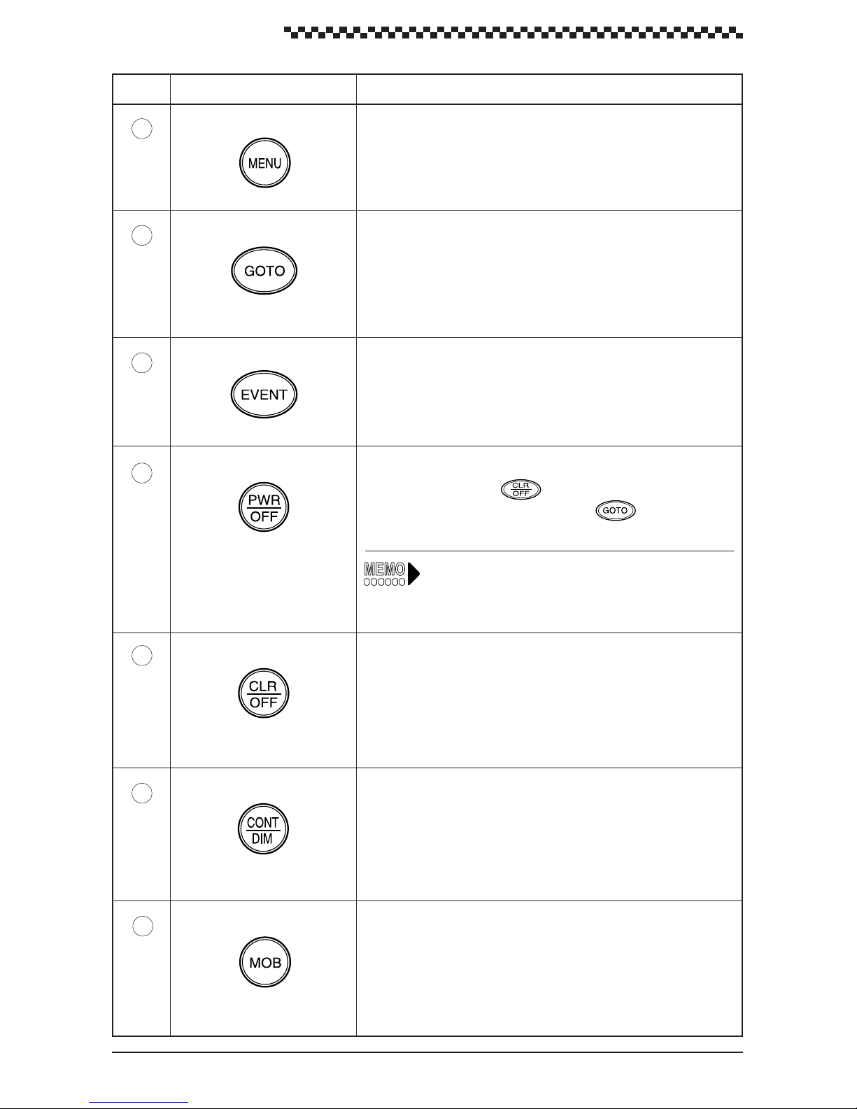
No. Name Function
3
4
5
6
GOTO
Event
Power
Displays the menus for each display mode.Menu
Use this key to select to destination (see Section 4.9, “Navigation
using direct routes (GOTO).” This key function is available in the
following display modes:
[ POSITION ] , [ NAVIGATION ] , [ CDI ] and [ PLOT ] displays
Registers the current position (buoy or fishing point) as a waypoint.
This key function is available in the following major display modes:
[ POSITION ] , [ NAVIGATION ] , [ CDI ] , [ PLOT ] and [ MOB ]
displays.
Turns on the power.
• Press this key and the key to turn off the power.
• Press this key while holding down the
soft reset.
key to perform a
Soft reset: All registered data except waypoints and
route plan are set to the default V alues (factory
settings).
7
8
9
Clear
Contrast
MOB
• Resets items before the dial was pressed.
• In the Select Mode display , press this key to return to the previous
display.
Adjusts contrast and brightness of the backlight. This key function
is available in all display modes.
Man overboard (position where a person fell overboard). This key
function is available in all display modes. (To return to previous
display mode, press this key for 3 seconds.)
14
Page 16
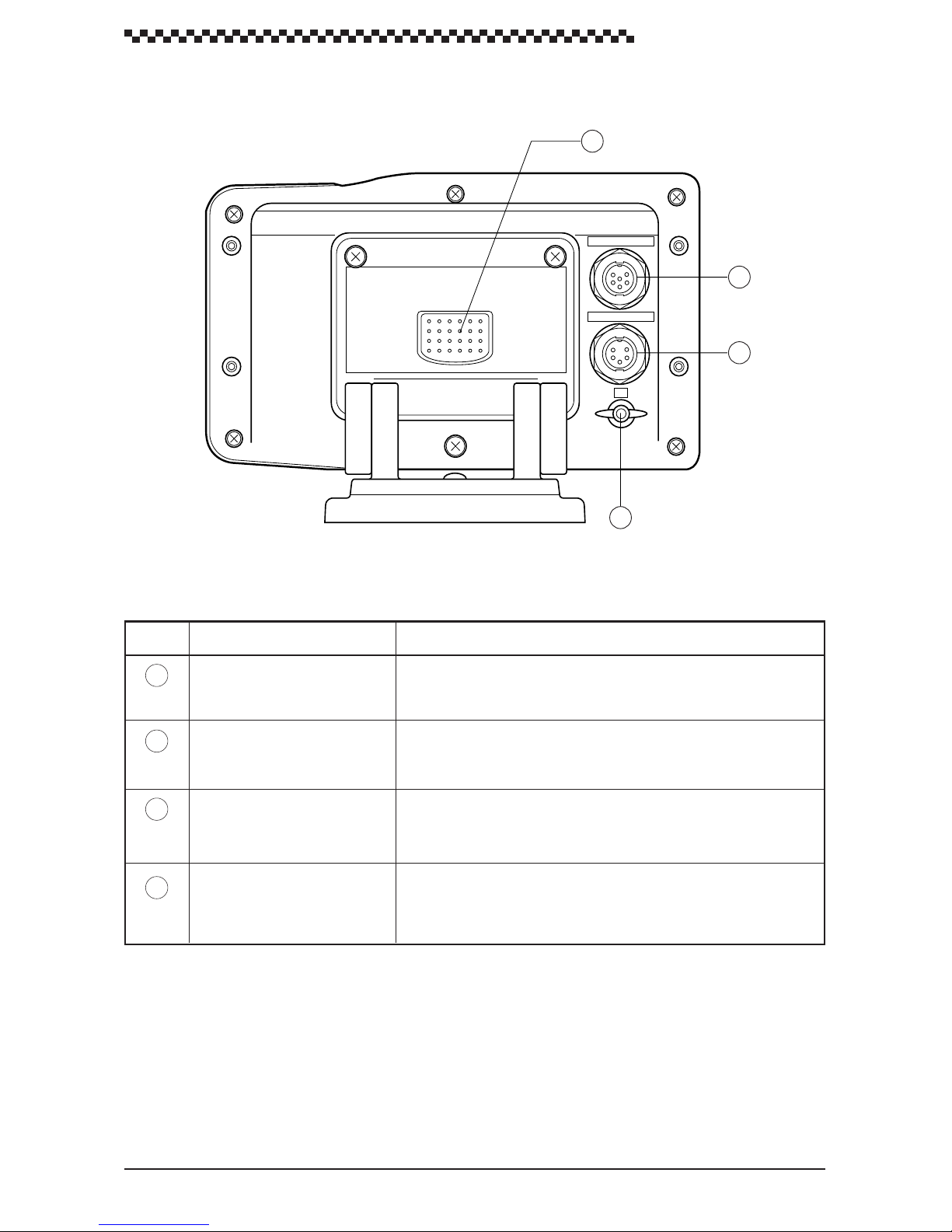
2.2 Rear panel
GPS Navigator J-NAV500
10
GPS/DGPS
11
DC PWR/DATA
12
E
13
Figure 2-2
No. Name Function
10
11
12
13
GPS/DGPS
DC PWR/DATA
E terminal
Press this button to remove the display unit from the bracket.Release button
Connector for GPS or DGPS receiver (GPS 100 or DGPS 200)
Connects supplied power cable.
(Includes data I/O lines)
Terminal for connecting to vessel ground.
15
Page 17
GPS Navigator J-NAV500
3. Installation
3.1 Display installation
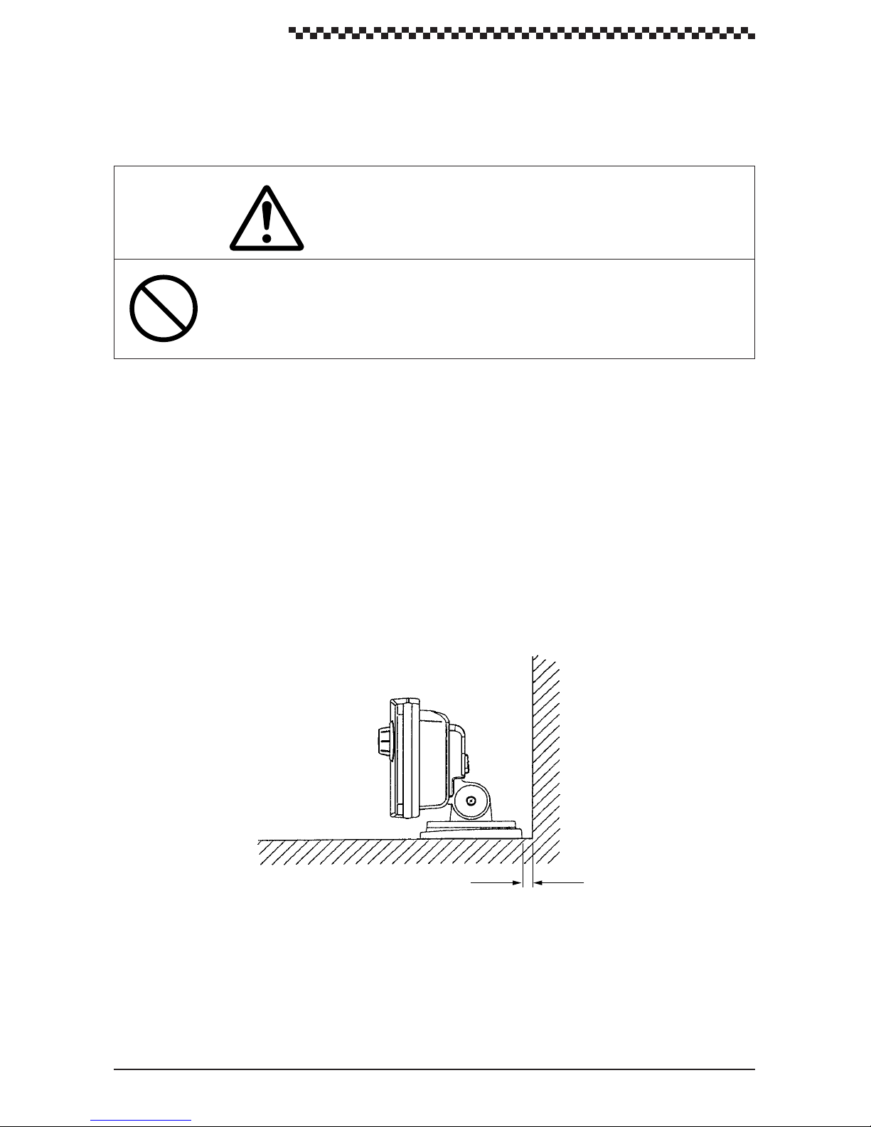
CAUTION
Install this unit at least 1 meter away from a magnetic compass. Otherwise, the unit
may cause the compass to indicate unreliably .
3.1.1 Choosing the location
When choosing a location to mount this unit, please consider the following two criteria for the site.
• The best location to provide ease of operation and viewing of the unit.
• The best location to provide protection from environmental elements. A void locations exposed
to direct sunlight and salt spray . Also avoid improperly ventilated locations and places exposed
to high temperatures.
The unit can be screw-mounted on a chart tabletop. Figure 3-1 shows the mount of free space required
around the unit.
UNIT : mm
10
10
Tabletop
Figure 3-1
Make sure that these space requirements are met.
16
Page 18
GPS Navigator J-NAV500
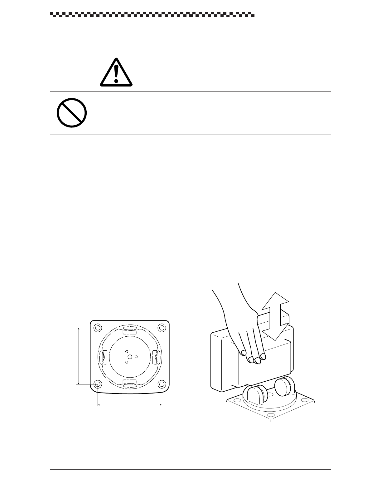
3.1.2 Mounting the unit
CAUTION
When installing this unit on a tabletop, use the designated screws to secure the bracket
to a stable wooden surface. Otherwise, the unit could fall and it may cause human
injury or property damage.
Mount the unit according to the following steps.
(1) Determine the mounting location of the unit and mark the holes of the four screws. Figure 3-2
shows the distance between the holes.
(2) Press the release button to remove the unit from the bracket. (See fig. 3-3)
(3) Secure the bracket to the mounting location with the four supplied tapping screws.
(4) Mount the display unit to the bracket. Make sure that the display unit is firmly attached to the
bracket.
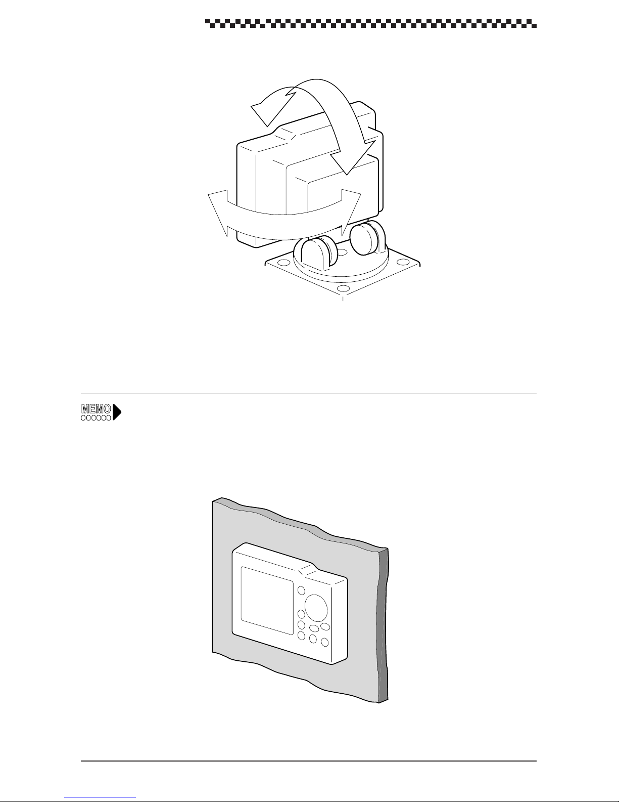
(5) Adjust the unit to the best viewing angle. (See fig. 3-4)
74.2
84
Figure 3-2 Bracket dimensions
UNIT : mm
Figure 3-3
17
Page 19
GPS Navigator J-NAV500
Figure 3-4
As shown below, an optional flush mount kit can be used to wallmount the navigator. For information
on mounting, refer to the instruction manual supplied with the kit.
18
Page 20
3.2 Cable connections
The connectors on the rear panel are shown in Figure 2-2.
CAUTION
When the GPS/DGPS receiver has been installed, route the surplus cable from the
receiver at a distance of 30 cm or more from this unit to prevent interference from
occurring in other communication devices.
GPS Navigator J-NAV500
3.2.1 GPS/DGPS receiver connection
The unit provides with a 12 VDC power supply for a GPS/DGPS receiver (GPS 100 or DGPS 200).
The GPS/DGPS receiver operates when the unit is turned on, and it displays current position and other
GPS status informations received from satellite signals.
Connection procedure:
Connect the GPS/DGPS receiver cable to the GPS/DGPS connector on the rear panel of the unit.
3.2.2 Power cable connection
WARNING
When the equipment is used with a “floating” battery , do not touch the ground connector on this unit and vessel ground simultaneously . Otherwise, you may suffer from a
electrical shock.
19
Page 21
GPS Navigator J-NAV500
Do not connect this unit and the GPS/DGPS receiver to ground when used with a
“floating” battery. Should they be connected to ground, large current will flow from this
unit or the GPS/DGPS receiver to ground and could cause fire or equipment breakdown.
When the data signal cables are not to be used, insulate the cable ends using
insulation tape to prevent cable short-circuit. Otherwise, the equipment may be
damaged.
Connect the red cable to the plus terminal and the black cable to the negative terminal
of the 12 VDC power supply . Note that reversing the cables could lead to equipment
damage.
CAUTION
Use only a fuse with the designated rating. Use of other fuses could lead to fire or
breakdown.
Model ; MF60NR-2A
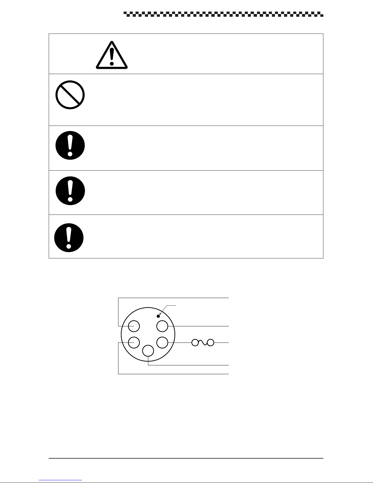
Figure 3-5 is a power cable wiring diagram. The power cable include the following wires: +12 VDC,
-12 VDC, DATA COM, DATA OUT+ and DATA IN+. Each wire is labeled.
White
Make indicating pin 1 location
5
4
1
2
Fuse 2A
3
Green
Yellow
Red
Black
DATA IN+
+12 VDC
–12VDC
DATA COM
DATA OUT+
Figure 3-5
The unit is intended for use on vessels with 12 VDC power systems and can operate as long as the DC
supply is maintained between 10.8 and 16 volts. The DC power system can be negative ground or can
be used without a ground connection in a ÔfloatingÓ power supply .
20
Page 22

GPS Navigator J-NAV500
However, the unit cannot be used on positive ground vessels.
Power lead connections
1. Connect the black -12 VDC power cable to the negative pole of the vessel battery.
2. Connect the red +12 VDC power cable to the positive pole of the vessel battery.
3. Firmly connect the power cables in the DC PWR/DATA connector on the rear panel of the unit.
• On a large ship, connect the power cable leads to the DC distribution board. Since a 2 A fuse is
used in the unit, connect it to a circuit breaker with 3 A or greater capacity .
• On a small ship, connect the power cables directly to the main battery insulation switch or breaker .
• Connect the unit to it’s own circuit breaker. Do not connect it to a circuit breaker also used for radar
and other equipment.
• To avoid electromagnetic interference, route the wiring of the unit as much as possible away from
other equipment.
• The power consumption of the unit is 6 watts when a GPS/DGPS receiver is connected; since line
loss becomes a problem at lengths of 3 meters or more, thicker cable has to be used. Use #12
AWG for cable length between 6 to 12 meters.
Data signal cable connections
The DATA OUT+, DATA IN+ and DATA COM signal cables can be used to connect to external
equipment using serial data connections. NMEA0183 sentences are output at all time.
Data signal cable connections
• Connect the DATA OUT+ (yellow), DATA IN+ (white) and DATA COM (green) cables to the
serial port of external equipment.
3.2.3 Ground connection
To connect to a beacon receiver with a whip antenna, a ground connection is required to improve
receiving performance. If the ship’s battery is a connected to negative ground, you can ground the
equipment using the hull of the vessel. If the ship’s battery is not connected to ground, use an insulating
DC-DC converter between the battery and the navigator before making a ground connection.
(Use an NBG-121 insulating converter for a 24 VDC battery.)
• Connect the E terminal on the back of the unit to the nearest vessel ground. Use #10 AWG or
thicker cable.
21
Page 23

GPS Navigator J-NAV500
3.3 EMC INSTALLATION & SERVICE GUIDELlNES
IMPORTANT NOTE
All JRC equipment and accessories are designed to the best industry standards for use in the marine
environment. Their design and manufacture conforms to the appropriate Electromagnetic Compatibility (EMC) standards, but good installation is required to ensure that performance is not compromised.
Although every effort has been taken to ensure that they will perform under all conditions, it is important to understand what factors could affect the operation of the product. Complete installation instructions are provided in Section 3 of this manual. Some preliminary suggestions are made below .
3.3.1 Installation
To avoid the risk of operating problems, all JRC equipment and cables connected to it should be:
• At least 1 m (3 feet) from any equipment transmitting or cables carrying radio signals e.g. VHF
transceivers, cables and antennas. In the case of SSB transceivers, the distance should be increased 2m (7 ft).
• More than 2m (7 ft) from the path of a radar beam. A radar beam can normally be assumed to
spread 30 degrees above and below the radiating element.
• The equipment should be supplied from a battery other than that used to start the engine. V oltage
drops below 10.8 V in the power supply to our products can cause the equipment to reset. Although this will not damage the equipment, it will cause loss of information and could change the
operating mode.
• Use JRC designated cables at all times. Cutting and rejoining these cables can compromise EMC
performance and should therefore be avoided unless specifically suggested in the installation
manual.
3.3.2 Check Before Going to Sea
• Always check the installation before going to sea to make sure that it is not affected by radio
transmission, engine starting, low battery voltage, or other problems.
• In some installations, it may not be possible to prevent the equipment from being affected by
external influences. In general this will not damage the equipment, but it can lead to it resetting, or
may momentarily result in faulty operation.
3.3.3 Servicing and Safety
• JRC equipment should be serviced only by authorized JRC service engineers. They will ensure
that service procedures and replacement parts used will not affect performance, There are no user
serviceable parts in any JRC product.
• The unit generates high voltages, so do not touch the cables or connectors when the power is on.
• Always report any EMC related problem to your nearest JRC dealer. W e will use such information
to improve our quality standards.
22
Page 24
GPS Navigator J-NAV500
4. Operation
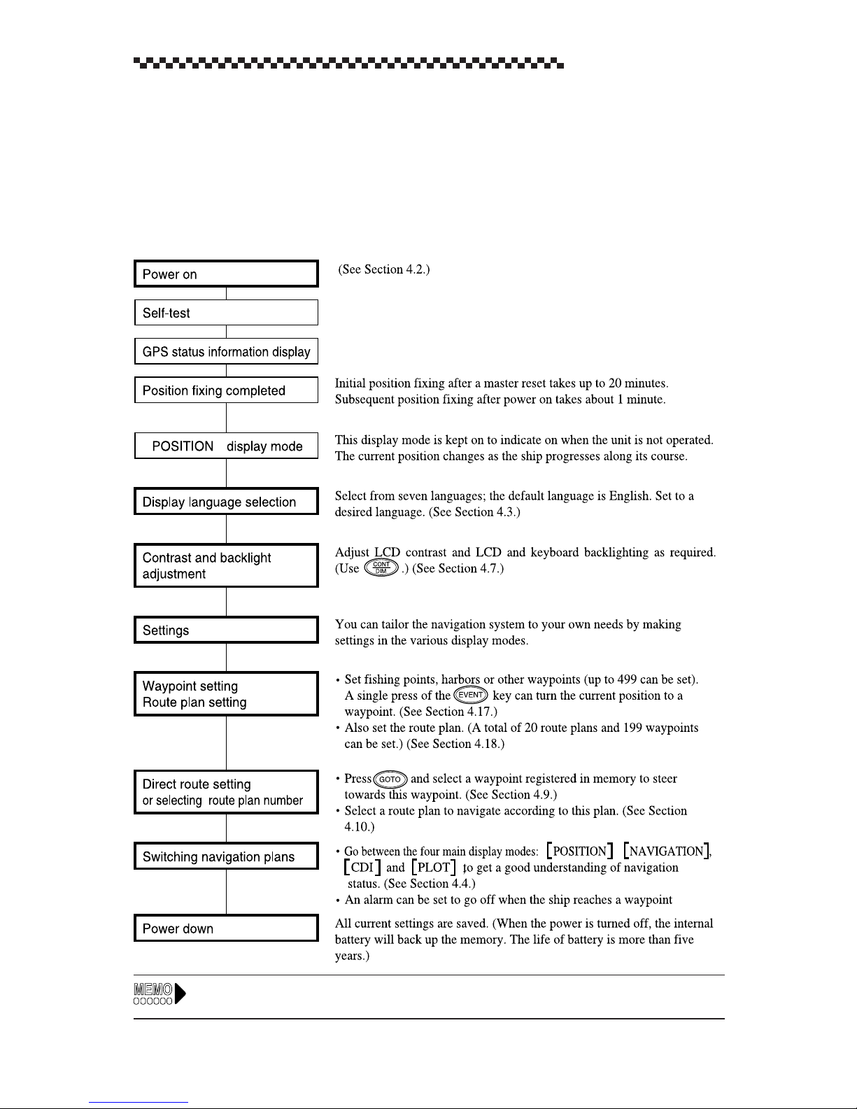
4.1 Overview
When the setup operations described in Chapter 3 have been completed, turn on the power to start
operation. This chapter describes the basic flow of operations. The bold line boxes indicate user operations.
For information on messages output during operation, see Message Table in Appendix A.
23
Page 25
GPS Navigator J-NAV500
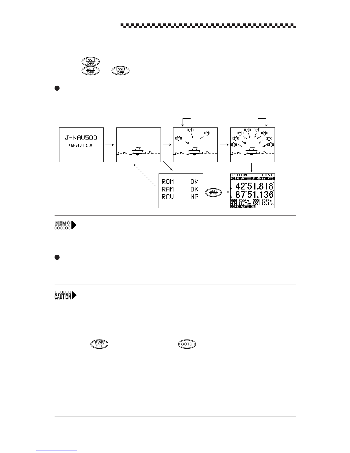
4.2 Turning the unit on/off
• Press to turn on the unit.
• Press and simultaneously to turn off the unit.
Display changes when the unit is turned on
When the unit is turned on, the displays are shown in the order given below: When position fixing is
completed, the [POSITION] display is shown.
[Self-test result][Version]
• Position fixing the first time the navigator is used or after a master reset takes about 20
minutes. (Subsequent position fixing takes about 1 minute.) To shorten this time, perform
the operation described in Section 4.19.2, Initializing GPS/DGPS receiver.
• For information on data error display, see the message list in Appendix A .
GPS status information
After position fixing
Master reset
This navigator is equipped with the following reset functions. For example, if the internal battery or the
ROM IC is replaced, a master reset would have to be performed.
When resetting the navigator, perform Initializing GPS/DGPS receiver as described in section 4.19.2
when correcting for local time.
1. Soft reset
This reset clears all data except registered waypoints and route plans.
• Key operated soft reset
Press the key while holding down the key.
• Menu selected soft reset
See Section 4.22, “To perform a master reset.”
2. Hard reset
This reset clears all data including registered waypoints and route plans.
• Menu selected hard reset
See Section 4.22, “To perform a master reset.”
24
Page 26
GPS Navigator J-NAV500
4.3 Selecting display language
The display language is set to English at the factory before shipment and reverts to this setting after a
master reset. Use the following steps to set it to desired language. One of the following seven language
can be set.
LANGUAGE: English (default)/
Display example
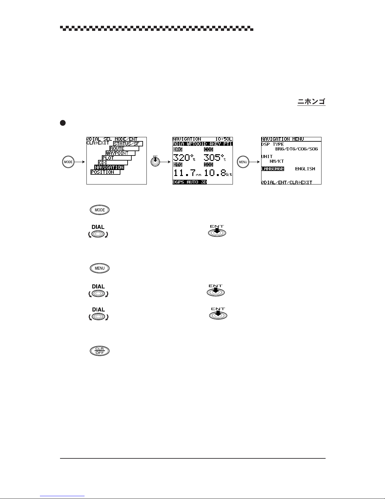
[Select Mode] [Navigation] [Navigation Menu]
(1) After position fixing, the [ POSITION ] display mode appears.
Press to display the Select Mode.
(2) Turn to select [ NAVIGATION ] and press to confirm it. This action displays the
[ NAVIGATION ] display mode.
(3) Press to display the [ NAVIGATION MENU ] .
Deutsch/Francais/Espanol/Norsk/Italiano/
‘
(4) Turn to select [ LANGUAGE ] and press . [ ENGLISH ] is now highlighted.
(5) Turn to select desired language and press . Check that the selected language is
displayed.
(6) Press to return to [ NAVIGATION ] display mode.
25
Page 27

GPS Navigator J-NAV500
4.4 Switching between Main Display Modes
This section describes how to switch between the Main display modes, then what display modes can be
selected from which main display mode. There are seven Main display modes. When the unit is
turned on and GPS position fixing is performed,
• POSITION : Displays current position and navigation information
• NA VIGATION : Displays bearing, distance, course deviation and other navigation information
• CDI : Shows a graphic representation of course deviation
• PLOT : Shows a graphic representation of track line and route line to waypoints
• WAYPOINT : Mode for displaying and setting waypoints
• ROUTE : Displays route plan numbers
• ST ATUS S/F : Displays a variety of GPS satelite information including beacon information
1. Switching between Main display modes
The example given below shows how to switch from the [ POSITION ] display mode to the
[ NAVIGATION ] display mode.
(The numbers in the text correspond to numbers in the illustration.)
Press to display the [ Select Mode ] display mode.
1
2
Turn to select the [ NAVIGATION ] display mode. [ NAVIGATION ] is highlighted.
the [ POSITION ] display mode.
Press (Dial). (In descriptions given below, pressing will be used to mean pressing
3
.) The [ NAVIGATION ] display mode appears.
All seven main display modes can be displayed in the same manner.
2. Screens that can be selected from the main display modes
As shown in the figure, the keys that can be used in each display mode are shown. As you get used to
operating the navigator, a glance at the figure will be all you need to know how to operate the navigator .
The following is a brief description of keys used in main display mode operations.
• :
• : Emergency key function used to mark a spot someone fell overboard. (This
• : Selects the menus of each Main display mode.
• / :
• :
• in the [
3. Selectable display mode from the Select Mode display
As shown in the figure, the [ Select Mode ] display shows the display mode and detailed menus after.
The following operations can be performed in these two modes.
• : Selects (highlights) Main display mode.
• or : Displays previous Main display mode.
Displays the
key is available in all modes.)
Sets the
[ POSITION ] , [ NAVIGATION ] , [
Adjust contrast and backlighting brightness. (This key is available in all displays)
PLOT
] display mode: Plot scale can be selected.
[ Select Mode ]
[
DIRECT ROUTE ] and
. This key is available in all modes except [ MOB ] .
[
EVENT
]
. (These keys are available in the
CDI ] and [ PLOT ] display modes.)
26
Page 28

GPS Navigator J-NAV500
Display Changes
[Select Mode display mode]
0.5 sec
[Main display modes]
[[STATUS] display mode]
[[ROUTE] display mode]
[[WAYPOUNT] display mode]
[[PLOT] display mode]
[Plot scale]
display mode
2
0.5 sec
To previous display mode
[[CDI] display mode]
[[NAVIGATION] display mode]
[
[POSITION] display mode
3
1
]
27
Page 29

GPS Navigator J-NAV500
4.5 Main Display Modes
This section describes how to interpret the seven main display modes.
• Display modes where waypoints and route plans have already been set are used in the examples.
• For information on items shared by each display mode, see Section 4.5.1, “Position display mode.”
4.5.1 POSITION display mode
This display mode shows current position and navigation informations. The following items are displayed in the [Position] display mode.
The data displayed in this display mode can be changed in the menus.
[Latitude/Longitude] display mode [Loran C Time Difference] display mode
Display mode name
Route plan number
Current position
Navigation
information
Position fix status Navigation alarm
1
Display mode name
Waypoint number Time
Waypoint name
Indicates that the [ POSITION ] display mode is shown.
2
Time (hour: min)
Displays the current time derived from GPS data.
The character L (default value) indicates local time and U indicates universal time.
(For more information, see Section 4.15, “Setting CDI range and Display Time Format.”)
3
Route plan number
Displays the currently selected route plan number (R01 to R20). The symbol A indicates that route
plan are automatically stepped. No symbol is displayed for manual step. (See Section 4.10, “Navigation
according to route plans.”)
The message “WPT NO DEST” is showed when no waypoint has been selected in a route plan or direct
route selection.
28
Page 30

GPS Navigator J-NAV500
Waypoint number
4
Displays the number of currently selected waypoint for destination.
Example: WPT 001 WPT: waypoint
001: waypoint number
When waypoints are registered through events, a “D” or “G” is appended to the waypoint number to
indicate the position fixing of GPS or DGPS, respectively .
5
Waypoint name
Displays the name registered for a waypoint.
Current position
6
The position is displayed in the following two ways.
1. Latitude and longitude (default)
2. Loran C time differences
The time difference display is designed for users of the Loran C navigation system.
(See Section 4.13, Position Display Mode/Position Correction/Geodetic System Correction/Magnetic
Compass Correction.)
Navigation information
7
Displays one of the following data
1. BRG/DTG/COG/SOG (default)
2. BRG/DTG/XTE/TTG
3. CMG/VTD/COG/SOG
• BRG :Bearing to destination (unit: )
• DTG :Distance to go to destination
Unit : nautical miles (nm) (default), sm, km
• COG : course over ground (unit: )
• SOG :average speed of ship (speed over ground )
Unit : kt (knots) (default) (when the distance unit is nm), mh (when the distance
unit is sm), kh (km/hour) (when the distance unit is km)
• XTE : Cross track error. Deviation from course and direction to steer (unit: 0.01 nautical miles)
Steering required to return to the planned course is indicated by L (left) and R
(right).
• TTG : Time to go until arrival at destination (unit: hour, minute)
• CMG : Bearing (unit: ¡) to the current position as viewed from the origin
• VTD :V elocity toward destination
Unit : kt (knots) (default) (when the distance unit is nm), mh (when the distance
unit is sm), kh (km/hour) (when the distance unit is km)
(See Section 4.14, “Setting Navigation Display Modes and Units.”)
29
Page 31

GPS Navigator J-NAV500
A “t” after the figure for BRG, COG and CMG indicates true bearing, while “m” indicates that
magnetic compass correction has been made.)
Position fix status
8
This position is displayed GPS position fix status.
When a problem has occurred in position fixing, HDOP, NO FIX or DGPS alarm is displayed.
For information on alarms, see Appendix A, “Message list.”
• When a GPS/DGPS receiver cannot calculate the position after one position fix, the message
[ No Fix ] is displayed and the alarm sounds. The alarm sounds can be canceled by pressing
.
• The alarm sounds once when the DGPS receiver switches from DGPS position fixing to
GPS position fixing. (When DGPS alarm set.)
9
Navigation alarm
Displays alarms by selecting.
• ARV (arrival alarm)
The alarm sounds and the characters AR V flash when the ship comes inside a set distance from a
waypoint.
• ANC (anchor alarm)
When the ship drifts beyond the set distance from a waypoint, the alarm sounds and the characters
ANC flash.
• XTE (off-course alarm)
When the ship strays off course by more than the set distance, the alarm sounds and the characters
XTE flash.
(See Section 4.8, “Setting Alarms (Arrival/Anchor/Off-course/DGPS).”)
Canceling alarms
• Press to cancel the alarm sounds.
• To disable the alarm display, set 0.00 as the alarm range. (See Section 4.8, “Setting Alarms (Arrival/Anchor/Off-course/DGPS).”)
30
Page 32

The operation of each alarm is described in the figures shown below.
GPS Navigator J-NAV500
ARV (arrival alarm)
The alarm goes off when the ship comes inside a
set distance of a waypoint.
Alarm
range
Position
Waypoint
Set
distance
XTE (Off-course alarm)
The alarm goes off when the ship strays more than a
set distance beyond its course.
Alarm
Origin
range
Set distance
Waypoint
Planned course
ANC (anchor alarm)
The alarm goes off when the ship goes beyond a
set distance.
Waypoint
Set
distance
Alarm range
31
Page 33

GPS Navigator J-NAV500
4.5.2 NAVIGATION display mode
This display mode shows the following navigation information.
The type of data displayed in this display mode can be selected in the menus.
Navigation information
[NAVIGATION] display mode is the type of information indicated in , “Navigation information”
7
described in Section 4.5.1, “POSITION display mode.” For details, see Section 4.5.1, “POSITION
display mode.”
1. BRG/DTG/COG/SOG (default)
2. BRG/DTG/XTE/TTG
3. CMG/VTD/COG/SOG
The above display mode appears when 1. is selected.
4.5.3 CDI display mode
This display mode offers a graphic representation of course deviation. It displays the data shown below .
The data displayed in this display mode can be changed in the menus.
Course deviation
Range of CDI
1
Course deviation
Shows the deviation from the set course and the direction to steer. (unit: 0.01 nm). The ( ) symbol
indicates that the ship should be turned left and the ( ) symbol indicates that it should turn right to
return to the set course. When the display indicates a deviation of 0.00, the ship will reach its destination by the shortest route.
32
COG
Waypoint symbol
@
SOG
Ship symbol
Track line
Page 34

GPS Navigator J-NAV500
2
COG
Course over ground (unit: )
“t” indicates true bearing and “m” indicates magnetic compass corrected value.
3
SOG
Displays the average speed (speed over ground) in kt (knots), mh, kh
4
CDI Range
Displays 0.1 (default), 0.3, 0.5 nm depending on setting.
(See Section 4.15, “Setting CDI range and Display Time Format.”)
4.5.4 PLOT display mode and setting the plot scale
1. PLOT display mode
This display mode offers a graphic representation of track line and the direct route from the vessel to a
waypoint.
The data displayed in the different display modes can be changed in the menus.
Waypoint symbol
Current position mark
1
Waypoint symbol
Plot scale
Waypoint and direct route of ship
Ship track line
Displays the first character in the registered waypoint name. The waypoint symbol can be turned on
(default value) or off.
(See Section 4.16, “Setting Plotting Information.”)
2
Current position mark
A “+” mark shows the current position of the ship.
3
Plot scale
The plot scale can be set in 10 steps between 0.125 nm to 100 nm. Scale refers to the size of the
horizontal area that the display shows.
2. Setting plot scale
(1) Press in the [ PLOT ] display mode.
This action displays the [ PLOT SCALE ] selecting mode.
(2) Turn to select plot scale and press .
This action returns to the [ PLOT ] display.
Setting scale: 0.125 (default), 0.25, 0.5, 1, 2, 5, 10, 20, 50, 100 nm
Plot scale
33
Page 35

GPS Navigator J-NAV500
4.5.5 WAYPOINT display mode
This display mode shows a list of registered waypoints.
Waypoint name
Waypoint number
D: registered DGPS position
G: registered GPS position
No indication:
registration other
than EVENT
Bearing to current position
Turn to scroll waypoint numbers and display each waypoint.
The waypoints registered in this display can be edited. (See Section, 4.17.1, Editing waypoints.)
4.5.6 ROUTE display mode
This display mode shows a list of registered route plan numbers.
The number of the route that is used is highlighted.
Date (date entered waypoint)
Waypoint position
Distance to current position
Number of route plan being used
Number of registered route plan
F
or information on how to execute route plans, see Section 4.10, Navigation according to route
plans.
34
Page 36

4.5.7 STATUS display mode
The [STATUS] display mode shows all relevant satellite data.
Satellite number
Azimuth angle
Elevation angle
GPS Navigator J-NAV500
Receiving level
Beacon status
Date
1
Satellite number
HDOP value
Antenna height
Displays numbers for the receiving satellites (8 of 01 to 32)
2
Azimuth angle
Displays the azimuth angle: N, NE, E, SE, S, SW, W, NW
Elevation angle
3
Displays the elevation angle to each satellite.
Receiving level
4
Displays the receiving level of each satellite. The greater the number, the higher is the level.
Beacon status
5
Displays the frequency , Baud rate and RSSI of DGPS beacon receiving signal.
RSSI: Receiving Signal Strength Indication
Date
6
Displays date derived from position fix. (month/day/year)
7
HDOP value
Indicates HDOP value. Position becomes more accurate as the HDOP value decreases. When the
HDOP value exceeds 4, the HDOP indicator flashes to notify that the positioning accuracy is poor.
Antenna height
8
In 3D mode, the height of the GPS/DGPS receiver obtained from position fixing is displayed.
Initial value are displayed when initialization is performed in 2D mode. (For details, see Section 4.19.2,
“Initializing GPS/DGPS receiver”). Initial values or the height obtained in previous 3D measurements
are displayed in an automatic mode.
35
Page 37

GPS Navigator J-NAV500
Tip HDOP level
A standard for assessing accuracy of position fixing. HDOP is based on the shape formed by the
positions of satellites and the receiver; a good shape yields a low HDOP level and an accurate
position fix value. A poor shape produces a high HDOP level and an inaccurate position value.
Satellites
A poor geometrical shape produces a high
HDOP level
A good geometrical shape produces a low
HDOP level
36
Page 38

GPS Navigator J-NAV500
4.6 Basic menu selection operations
The use of the has already been described in sections 4.3, “Selecting display language” and
4.4, “Switching between Main Display Modes.” This section will describe menu selections in detail.
The can be turned and pressed to select and confirm selected menus; familiarize yourself with
it and you will be able to speedily select menus and confirm selections.
Read through this section carefully since what follows assumes a knowledge of what is described
here.
Keys used to select and set menus
• Turn : selects menu or menu items.
• Press (Press is used to mean press ): Menus and menu items that have been
selected by turning. are entered.
• Press :
• When pressed before a menu item has been set or entered, it cancels that selection and returns
you to the previous menu.
• When pressed after a menu item has been set or entered, it returns you to the previous menu.
•The next menu to be selected is highlighted when a menu has been selected and confirmed.
Thus select and confirm items as they are highlighted to complete all the settings in a menu.
• Brief key instructions are given along the bottom of the screen to help you with entries.
Example: (DIAL/ENT/CLR EXIT) in the figure below means: Turn to select /press
to confirm/press to return to previous menu).
Operation examples
Detailed descriptions for setting in the position display type and position correction in the [POSITION
MENU].
Press the key in the [ POSITION ] display mode to display this menu.
L/L TD
[Position] display mode
Menu Selection item
N 00.000' W 00.000'
S E
Select All
(Items cannot be displayed
due to lack of space appear
when selected.)
37
Page 39

GPS Navigator J-NAV500
1. Setting position display type
(1) Turn in the [POSITION MEN] display mode to select the [L/L OR TD] menu.
[L/L OR TD] is highlighted and currently selected item [L/L] is displayed.
(2) Press to confirm [L/L OR TD] selection.
All selected items are displayed and currently selected item [L/L] is highlighted.
(3) To change to [TD], turn to select [TD] and press to confirm.
(When [L/L] is the selection you wish to make, press to cancel the last selection.)
This action returns you to the [L/L OR TD] menu and [L/L OR TD] is highlighted.
2. Position Correction (latitude, longitude) menu setting
(1) Turn in the [POSITION MENU] display and press to select the [POS CORR]
menu. [POS CORR] is highlighted and the currently set value is displayed.
(2) Press to confirm [POS CORR].
The next item, [N] is highlighted.
(3) If [N] is the selection you wish to make, press . If you wish to select [S], turn to
select [S] and press to confirm the selection.
[00] is now highlighted.
(4) Turn to select the desired value and press to confirm the selection.
[000] is highlighted.
(5) Turn to select the desired value and press to confirm the selection. This action
corrects the latitude setting.
The next item to be set, [W] is highlighted.
(6) Repeat steps (3) to (5) to set longitude.
The [POS CORR] menu is displayed and [POS CORR] is highlighted.
(7) Press to return to the previous display.
• Use the key to amend number entries during settings.
Example: Amending a number entry made in step (3) above
When [00] has been confirmed, [000] is highlighted. Before confirming [000], press .
This action causes [00] to be highlighted and allows you to amend the [00] setting.
• Turning rapidly, changes the figures at high speed.
38
Page 40

GPS Navigator J-NAV500
4.7 Adjusting Contrast and Backlighting
This function adjusts contrast and backlighting in all displays.
(1) Press .
This action displays the display for changing the contrast and backlighting.
(2) Turn to select the desired contrast.
Range of contrast selection:
(3) Press . Each press of the key toggles the setting between High and Low.
Backlight setting:
(4) Press or wait for 5 seconds to return to the previous display mode.
HI/LOW
00 to 15
(default)
(default value: 07)
4.8 Setting Alarms
(Arrival/Anchor/Off-course/DGPS)
The navigator is provided with four types of alarms that can be set to inform you of important changes
during navigation.
Note that set alarms will go off whether you have selected a route plan or when you use the
function (see Section 4.9, “Navigation using direct routes (GOTO).” ).
Before reading the following sections, read Section 4.6, “Basic menu selection operations.”
1. Selecting displays
(1) Press in the [ROUTE] display mode.
(2) Turn to select [Alarm] and press . This action displays the •uAlarm•v setting
mode.
(3) To return to the [ROUTE] display mode, press twice.
Display example
[Route] display mode
39
Page 41

GPS Navigator J-NAV500
2. Setting
1) Arrival alarm
The arrival alarm can be set to alert you when
you are within a specified distance from your
waypoint. The arrival alarm can be set within a
range of
0.00 to 9.99 nm
.
• A setting of 0.00 turns off the alarm.
• This alarm is also valid in direct route navigation.
• When following a route plan, the arrival alarm
selected in setting up the route plan takes priority. (See Section, 4.10 “Navigation according
to route plans.”)
2) Anchor alarm
The anchor alarm is intended to be used to moni-
tor your ship’s position while at anchor . The alarm
goes off when the ship drifts beyond the entered
distance. This distance beyond which the alarm
will be triggered can be set in a range of
9.99 nm
.
0.00 to
• A setting of 0.00 turns off the alarm.
Position
Waypoint
Set
distance
Alarm range
Waypoint
Set
distance
Alarm
range
Since the settings of the arrival alarm and
anchor alarm conflict, you can only set an
arrival alarm or an anchor alarm, but not both
together.
When both alarms are set, the last made
setting is valid.
3) Off-course alarm
This alarm sounds when you stray more than a
set distance off a set course. A distance in a range
of
0.00 to 9.99 nm
can be set.
• A setting of 0.00 turns off the alarm.
4) DGPS alarm
This alarm sounds once to notify that GPS posi-
tion fix values will be used instead of DGPS position fix values.
DGPS alarm on (default)
/off
Origin
Alarm
range
Waypoint
Planned course
Set distance
40
Page 42

GPS Navigator J-NAV500
4.9 Navigation using direct route [GOTO]
A registered waypoint number can be selected as a direct destination by pressing and entering
a waypoint number. The function is available in the following four main display modes:
• [POSITION], [NAVIGATION], [
The procedure to make direct route selection is the same in four display modes. In the example
below , sho ws how to do this from the [CDI] display mode.
(1) Press .
The [DIRECT ROUTE] display mode appears and [GOTO
WPT_ _ _] on the second line is highlighted.
(2) Select the number of the desired waypoint in registerd waypoints.
Example: To set 050
Turn until 050 is displayed and press to confirm the
selection.
You can now use the [CDI] display mode to steer you towards the selected waypoint.
Canceling a direct route
To cancel a direct route (or a route plan in operation), press and enter waypoint number [000].
To enter a new direct route, perform steps (1) to (2) above.
CDI] and [PLOT
] display modes
When a direct route is used in the plot display mode, press the to display the waypoint
numbers beside the waypoint symbols.
41
Page 43

GPS Navigator J-NAV500
4.10 Navigation according to route plans
Select the number of the route plan you wish to follow. When the number of the route plan has been
selected, perform the settings in the displays that appear.
For information on route plans, see Section 4.18, "Setting Route Plans."
Display example
[Route Plan] display mode
(1) Press in the [ROUTE] display mode to display the [Route Menu].
(2) Turn to select [FOLLOW ROUTE] and press to confirm the selection. This action
displays the [FOLLOW ROUTE] display.
(3) Turn to select desired route plan number (04 for the example) and press .
(4) This action selects [SEQUENCE MODE].
(5) Turn to select one of the following and press .
•
Auto
: automatic step of waypoints
•
Manual
•
Off
: manual step of waypoints
: no route plan is set
(6) [DIRECTION] is now selected.
(7) Turn to select one of the following and press .
•
Forward
•
Reverse
: Displays waypoints of the route plan in the order they were set
: Displays waypoints of the route plan in the reverse order
(8) Turn to select values for [SET ARRIV AL DISTANCE] and press .
Setting range:
0.00 to 9.99 nm
The [Position] display mode is now displayed automatically.
42
Page 44

The alarm setting made in Section, “4.8 Setting Alarms (Arrival/Anchor/Off-course/DGPS)” are
replaced by the arrival alarm distance made here.
The route plan numbers entered here are highlighted in the [Route] display mode. An automatic step
cannot be performed by selecting [Auto] in step (5) when [0.00] is set in [Set Arrival Distance]. To
make an step, press , like in manual step, to step the waypoint. When a value between 0.01
to 9.99 is entered, the alarm sounds when the vessel enters within the set arrival alarm zone from
the waypoint.
Auto step: Function that automatically steps from one waypoint to the next when the arrival
perpedicular point has been deleted.
Manual step: The next waypoint is stepped by pressing . When is pressed as the
vessel enters the set arrival alarm zone to step to the next waypoint, the alarm is canceled. If
is not pressed to perform an step when the vessel enters the set arrival alarm zone, the alarm will
ring until turned off by pressing . (Manual stepping is valid in [ POSITION ], [ NAVIGATION
], [ CDI ] display modes.)
4.11 Entering current position as a waypoint
GPS Navigator J-NAV500
[EVENT]
The current position (buoy or fishing ground) can be turned into a waypoint
simply by pressing . The function is available in the following five main display modes.
• [POSITION], [NAVIGATION], CDI, [PLOT] and [MOB] display modes.
The procedure to enter the current position as a waypoint is the same in five display modes. The
example below shows how to do this from the [ POSITION ] display mode.
(1) Press at the position you wish to add as a waypoint. The [ EVENT ] display appears in
place of the [ POSITION ] display.
After [ EVENT ] , the lowest unregistered number is displayed on the second line.
(2) The current position is now registered to the desired number.
• When you wish to register the waypoint to the number that is first displayed, press . Or
just wait 5 seconds until the [ EVENT ] display disappears.
• Use the following procedure to register the waypoint to a different number .
Press and turn to select a number. Then press .
• Number of registration: 001 to 499
• When a number where a registration has already been made is selected for registration, the
message, “NOW USING”, “IN ROUTE”, “DEST PT” are indicated and no registration is made.
• Events cannot be registered when the GPS/DGPS receiver is not position fixing.
When events are registered during GPS/DGPS position fixing, the following symbols are appended
to the waypoint list:
DGPS position fixing: D
GPS position fixing: G
43
Page 45
GPS Navigator J-NAV500
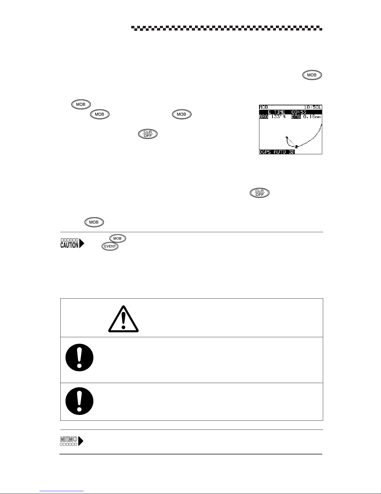
4.12 Man-Overboard Mode
The MOB function (Man-overboard) is useful if something or someone falls overboard. Press
and the navigator shows a graphic display of the position allowing you to steer back to the position
where the event occurred.
The function is available in all display modes.
(1) Press . This action enters the display mode. The ship
and the MOB position are connected by a dotted line. (The alarm can
be canceled by pressing .)
(2) The display shows the bearing, distance and elapsed time (minutes and
seconds) from the MOB position.
You can now steer back to the MOB position using the display information.
• The plot scale is automatically set to 0.5 nm. An arrival alarm sounds when the ship is inside 0.1
nm of the MOB position. (The alarm can be canceled by pressing .)
(3) The MOB function can be canceled and the previous display mode can be redisplayed by press-
ing for 3 seconds.
Pressing does not store the MOB position in memory. To store the MOB position in memory,
press and register the MOB position to desired number. (For details, see Section 4.11,
“Entering current position as a waypoint [EVENT].”
4.13 Position Display Mode/Position Correction/Geodetic System
Correction/Magnetic Compass Correction
CAUTION
Make it a rule to check the geodetic system marine chart and this unit setting before
going to sea. If both geodetic systems are wrong, the displayed latitude and longitude
indications will differ from those of the actual position of the ship, which could lead to a
marine accident.
The automatically corrected compass value is an approximate value. For this reason,
manually enter the correct value when you wish to steer the ship on a correct course
according to corrected magnetic compass values.
See Section 4.6, "Basic menu selection operations" for information on setting procedures.
44
Page 46

GPS Navigator J-NAV500
1. Display operations
• Press in the [POSITION] display mode.
• To return to the [POSITION] display mode, press .
Display example
[Latitude, Longitude display] [Time Difference Display]
2. Setting
(1) Display format
The [POSITION] display mode can be set to one of the following display formats.
L/L OR TD
L/L
: latitude, longitude display (default)
TD
: Time Difference display
(2) Position correction
Use this function to adjust the positioning GPS/DGPS sensor to marine chart.
POS CORR
N 00.000’
for latitude correction (in L/L display format)
S
POS CORR
W 00.000’
for longitude correction (in L/L display format)
E
TD correction
TD1
TD2
+
+
0.0
for TD1 correction (in TD display format)
0.0
for TD2 correction (in TD display format)
(3) Geodetic system correction
The latitude and longitude of the positioning data can be converted to latitude and longitude data
of another geodetic system. There are a total of 46 geodetic systems. The names of the first nine
systems are displayed by name and the rest are displayed by number. The names of the other
geodetic systems are listed in Appendix B, “Geodetic System T able.”
GEODETIC See Appendix B, “Geodetic System T able.”
(4) Magnetic compass correction
Magnetic compass correction
AUTO
MANU E
(Automatic magnetic compass correction)
00 (Manual magnetic compass correction)
W
In a manual setting, it is possible to read the magnetic compass variation from the compass chart of
a marine chart. Example: When the magnetic compass shows a reading of 60 and the navigator
indicates 40 , the (W) 20 difference can be used to correct the navigator setting.
45
Page 47

GPS Navigator J-NAV500
The correction value may differ with the sea area. If so, correct as required.
4.14 Setting Navigation Display Modes and Units
1. Display operations
• Press in the [NAVIGA TION] display mode.
• To return to the [NAVIGATION] display mode, press .
2. Setting
(1) The navigation information can be displayed in one of the following
type.
DSP TYPE BRG/DTG/COG/SOG (default format)
BRG/DTG/XTE/TTG
CMG/VTD/COG/SOG
CMG and VTD are described in the figure below.
CMG : Bearing of the current position as viewed from origin of route
VTD : Velocity toward destination
North
(2) Unit
The following navigation information units can be set.
UNIT :
NM/KT SM/MH KM/KH
Origin
Planned route
b
(3) Display language
One of the following seven languages can be set.
LANGUAGE: English (default)/
Deutsch/Francais/Espanol/Norsk/Italiano/
North
Current
position
‘
a
V (velocity)
VTD
VTD = V cos a
CMG = b
Waypoint
46
Page 48

GPS Navigator J-NAV500
4.15 Setting CDI range and Display Time Format
1. Display operations
• Press in the [CDI] display mode.
• To return to the [CDI] display mode, press .
2. Setting
(1) CDI range
The CDI range can be set as follows:
CDI RANGE:
(2) Display time format
Time can be displayed according to the following formats:
TIME DSP:
0.1
Local
(default),
(default)
0.3, 0.5 nm
UTC
(universal time)
4.16 Setting Plotting Information
1. Display operations
• Press in the [PLOT] display mode.
• To return to the [PLOT] display mode, press .
2. Setting
(1) Track storage interval
The navigator can be record the track line by time or distance. A total of 499 points can be
recorded and the memory is updated as new data is received.
TRACK INTER VAL
Setting a shorter storage interval, increases the accuracy of the track line, but uses up the total of
499 points in a shorter time. Longer intervals increase storage time but reduces accuracy of the
track line.
(2) Erasing track line
TRACK ERASE
This function cancels track line displayed in the [PLOT] display mode.
.5/1/3/5/10 minutes
.2/.5 nm
(approx. 100/250 nautical miles)
(approx. 250 min to 83 hours)
/off
(no data is stored) (default)
(3) Displaying track line
The track line display can be turned on and off.
TRACK LINEon (default)
/off
47
Page 49

GPS Navigator J-NAV500
(4) Waypoint symbol
It is possible to display the first letter of the waypoint name as a waypoint mark on the display.
This display function can be turned on and off.
MARKS
on
(default)
/off
4.17 Entering Waypoints
Waypoints can be entered in one of the following four ways:
• Using to store a waypoint
Press when you pass a fishing point or buoy and enter the desired waypoint number. (See
Section 4.11, “Entering current position as a waypoint [EVENT].”)
• Entry of latitude/longitude (When the [L/L] is selected.)
Direct entry of latitude/longitude coordinates from marine charts or other navigation information.
• Entry of Loran C time difference(When the [T/D] is selected.)
Direct entry of Loran C time difference TD1 and TD2. (For those who are used to time difference
data)
• Entry of bearing and distance
Direct entry of bearing and distance from current position of the ship can be calculated.
Up to 499 waypoints can be entered which are numbered from 001 to 499.
To store new numbers and to recall old ones, a number must be entered.
Thus it is a good idea to record the waypoint number and waypoint name in the waypoint list in Appendix
E. (Or in a copy of this list.)
The following function can be used to look for a registered waypoint.
• Sorting the waypoint list in number order (default) or in alphabetic order.
48
Page 50

GPS Navigator J-NAV500
WAYPOINT display mode and waypoint menu
• The [WAYPOINT] display mode is used for displaying and editing waypoints. (See Section
4.17.1.)
• The following settings can be made in the [WAYPOINT MENU] displayed by pressing
in the [WAYPOINT] display mode.
• W aypoint setting (latitude, longitude/TD/bearing, distance) (See Section 4.17.2.)
• Erasing, copying and measuring waypoints (See Section 4.17.3.)
• Sorting waypoint lists (See Section 4.17.4)
Display example
[WAYPOINT Menu] display
[WAYPOINT] display mode [Latitude, longitude display format] [TD display format]
or
For information on entry procedures, see Section 4.6, “Basic menu selection operations.”
4.17.1 Editing Waypoint Lists
Registered waypoints can be displayed in the [WAYPOINT] display mode and edited them.
(1) Scroll the list in the [WAYPOINT] display mode and select the number to be edited and press
. This action displays the [WAYPOINT LIST EDIT] display.
(2) Edit the waypoint and enter it again. This returns you to the [WAYPOINT] display mode.
[WAYPOINT] display mode [WAYPOINT LIST EDIT] display
49
Page 51

GPS Navigator J-NAV500
4.17.2 Storing waypoints
1. Storing by LAT/LON (When the [L/L] is selected.)
Use the following procedure to enter waypoint by latitude and longitude.
(1) Press in the [WAYPOINT] display mode. This displays the [W AYPOINT MENU] .
(2) Press to select [ENTER NEW WPT BY L/L] and press . The lowest number that
can be entered is displayed. (For the example 001 has been registered.)
Display example
[First Display]
[Display showing made entries]
[Bearing, distance calculation results]
[WAYPOINT
MENU]
[WAYPOINT
MENU]
(3) Select waypoint number and press . If the displayed number is the right one, just press
(4) Enter the name of the waypoint in up to 8 characters.
The alphabet (26 characters), numbers (0 to 9), symbols (6) and spaces can be used for name
entries.
Symbol: ( )
Example: Fish 3
• Turn to select symbol [ ] and press .
•Turn to select space and press .
•Enter up to 8 characters using this procedure.
Since the first character of a waypoint name is displayed as a symbol of the waypoint in [PLOT]
display mode. It is a good idea to select a symbol or alphabetic character for the first letter.
(5) Set latitude and longitude in stated order.
N XX XX. XXX' W XX XX. XXX'
S E
When the entry has been made, the message “CALCULATING” is displayed indicating that the
bearing and distance from current position is being calculated. The calculation result is displayed
at the bottom of the screen.
50
Page 52

GPS Navigator J-NAV500
2. Storing by TDs (TD1, TD2) (When the [TD] is selected.)
Use the following procedure to enter the position of a waypoint using time differences.
(1) Press in the [WAYPOINT] display mode. This displays the [WAYPOINT MENU] .
(2) Turn to select [ENTER NEW WPT BY TD] and press .
Display example
[First Display]
[WAYPOINT
MENU]
[Display showing made entries]
[WAYPOINT
MENU]
(3) As in 1, select waypoint number and name, and press .
(4) Enter TD1 and TD2. (When the [TD] is selected.)
[GRI] displayed in the [TD conversion input] is [ESTIMATED TD] made in [STATUS/SF MENU] (See
Section 4.19.3, “TD initializing”)
3. Storing by bearing and distance
Use the following procedure to enter bearing and distance to be used in calculating waypoint position.
(1) Press in the [WAYPOINT] display mode. This displays the [WAYPOINT POINT] .
(2) Turn to select [ENTER NEW WPT BY B/R] and press .
Display example
[Waypoint
Menu]
(3) As in 1, enter waypoint number and name, and press .
(4) The bearing and distance from current position is entered.
When the entry is complete, the message “CALCULATING” is displayed.
[First Display]
[Display showing made entries]
[Waypoint
Menu]
51
Page 53

GPS Navigator J-NAV500
4.17.3 Erasing, copying and measuring waypoints
The following three functions are described below .
• Erasing waypoints: Erasing waypoints no longer required.
• Copying waypoints: Copies registered waypoints. For information on how to edit copied waypoints,
see Section 4.17.1, “Editing W aypoints.”
• Measuring between waypoints: Bearing and distance between any two registered waypoints can
be measured.
Display example
[ERASE/COPY/MEASURE] display [ERASE] display
[WAYPOINT
NEMU]
[MEASURE] display [COPY] display
1. Erasing waypoints
(1) Press in the [WAYPOINT] display mode.
(2) Turn to select [ERASE/COPY/MEASURE] and press .
(3) Turn to select [ERASE WAYPOINT] and press .
(4) Turn to select the number of the waypoint to erase and press .
The message [ARE YOU SURE? ENT] appears.
¥ Press to erase.
¥ Press to cancel erasure.
52
Page 54

GPS Navigator J-NAV500
2. Copying waypoints
(1) Press in the [WAYPOINT] display mode.
(2) Turn to select [ERASE/COPY/MEASURE] and press .
(3) Turn to select [COPY WAYPOINT] and press .
(4) Enter the number of the waypoint to be copied in the [FROM] field.
(5) Enter the number of the destination of the waypoint in the [TO] field. The waypoint has been
copied.
If the number of an already registered waypoint is selected as the destination, it will be overwritten by
the copied waypoint.
2. Measuring between waypoints
(1) Press in the [WAYPOINT] display mode.
(2) Turn to select [ERASE/COPY/MEASURE] and press .
(3) Turn to select [MEASURE WAYPOINT] and press .
(4) Enter the number of the waypoint to be used as the origin in the [FROM] field.
(5) Enter the number of the waypoint to be used as the end point in the [TO] field.
The bearing and the distance between the waypoints is calculated and the result is displayed at the
bottom of the screen.
53
Page 55

GPS Navigator J-NAV500
4.17.4 Sorting waypoint list
The waypoint list can be sorted either in number order or in the alphabetic order of the waypoint names.
In alphabetic order, characters are sorted in the following order: symbols, alphabetic characters, numbers
and spaces.
(1) Press in the [WAYPOINT] display mode. This displays the [WAYPOINT MENU] .
(2) Turn to select [WPT SORT] and press .
(3) Turn to select
123
or
ABC
and press .
123 (default): sorts the waypoints in number order
ABC: sorts the waypoints in alphabetic order.
Display example
[Waypoint display for ABC sort]
[WAYPOINT
MENU]
4.18 Setting Route Plans
A route consisting of several connected waypoints is called a route plan. For example, say that you go
from a harbor (waypoint number 010), to a fishing point (waypoint number 011), to another fishing
point (waypoint number 012) and then return to a different harbor (waypoint number 013).
Harbor AA
(waypoint number 010)
(waypoint number 011)
Fishing point
Fishing point
(waypoint number 012)
Harbor BB
(waypoint number 013)
This route plan thus consists of harbor AA and the destinations which are the two fishing points (waypoint
numbers 011 and 012) and harbor BB (waypoint 013). In following a set route plan, the navigator
switches from one waypoint to another when it comes within a certain distance from the first waypoint
(automatic stepping of waypoints). In automatic stepping, when the ship comes in the range set for the
waypoint arrival alarm, the waypoints are stepping.
• For information on entry operations given below, see Section 4.6, “Basic menu selection
operations.”
• For information on how to follow route plans, see Section 4.10, “Navigation according to route
plans.”
54
Page 56

4.18.1 Making route plan
The following displays are used for making route plans.
Display examples
[Route Plan] display mode
GPS Navigator J-NAV500
Repeat
(1) Press in the [ROUTE] display mode. This displays the [ROUTE MENU] .
(2) Turn to select [MAKE ROUTE] and press .
This displays the [ROUTE MENU] .
This displays the [MAKE ROUTE] display and the numbers that can be used for a new route
plan. (The display above shows that 02 and 04 are already taken.)
(3) Turn to select desired route plan number (01 in the example) and press .
The display title changes to [MAKE ROUTE #01] .
(4) Enter the origin of waypoint number 001 in the [FROM] field for the first route (LEG 001) of
route plan #01. (The name of route number 001 is shown in the display . )
(5) Enter the number of the next waypoint in the [TO] field.
The entries made for route (LEG 001) and the calculated bearing and distance between the two
waypoints are displayed.
• Press to end a route plan.
• To enter the next route (LEG 002 to), repeat steps (4) and (5).
You can use steps (4) and (5) to enter up to 20 routes consisting of up to 199 waypoints.
55
Page 57

GPS Navigator J-NAV500
4.18.2 Editing route plan
Routes can be inserted to or deleted from registered route plans as you wish.
Use and in the [Edit Route] display mode as shown below.
• : Key for inserting waypoint numbers
• : Key for deleting waypoint numbers
Display examples
[ROUTE] display mode
[Delete]
[Insert]
[Made Route] [Erase waypoint 003] [Insert waypoint 005]
003
Leg 002
012
Leg 001
001
Leg 002
002
005
Leg 003
012
003
Leg 004
Leg 001
001
002
Leg 002
003
012
Leg 003
Leg 001
001
002
(1) Press in the [ROUTE] display mode.
(2) Turn to select [EDIT ROUTE] and press .
(3) Turn to select desired route plan number (02 for the example) and press . The
display mode title changes to [EDIT ROUTE #02].
56
Page 58

GPS Navigator J-NAV500
(4) This example will show how to delete waypoint 003 from LEG 002 and to insert a new waypoint
005.
• Deleting waypoint #003
As shown above, turn to select LEG002 and press to confirm LEG002.
Press to delete #003 of LEG002. This deletes waypoint #003 and the number of leg are
decremented.
• Insert waypoint #005
As shown above, turn to select LEG002 and press to confirm LEG002.
Press , enter #003 for #005 and press .
Waypoint #005 is inserted and the number of leg are incremented.
Tip You cannot edit a route plan that is being executed.
4.18.3 Erasing route plans
Registered Route plans can be erased using the procedure described below.
Display example
[Route Menu]
[ROUTE]
display mode
(1) Press in the [ROUTE] display mode.
(2) Turn to select [ERASE ROUTE] and press .
(3) Turn to select the desired route plan number (02 for the example) and press . This
displays the message [ARE YOU SURE? ENT].
(4) Press once more to erase the selected route plan after which the [ROUTE MENU] ap-
pears.
• To cancel deletion, press .
57
Page 59

GPS Navigator J-NAV500
4.19 Setting GPS information
For information on entry operations given below, see Section 4.6, “Basic menu selection operations.”
Display examples
[STATUS] Display Mode [STATUS/SF Menu]
4.19.1 Setting position fix mode and averaging for GPS
1. Setting position fix mode
(1) Press in the [STATUS] mode display.
This action displays the [STA TUS/SF MENU] .
(2) Turn to select [FIX MODE] and press .
(3) Enter 2D or Auto (default)
•
2D
•
Auto
(2D or 3D are automatically selected)
During GPS position fixing When the correct antenna height is entered, [2D] becomes more accurate
than [3D].
• During DGPS position fixing, “auto” is used regardless of selection in [FIX MODE].
2. Setting Averaging Time
This navigator calculates position, ship speed and course using signals sent from GPS satellites. The
problem with this data is the dispersion introduced by satellite location and receiving conditions. T o
average this dispersion, you can set the desired averaging time from 01 to 99 seconds.
Large values reduces dispersion. Small values increases dispersion, but you can more speedily track
the conditions of the ship.
(1) Press in the [STA TUS] mode display.
This action displays the [STA TUS/SF MENU] .
(2) Turn to select [AVERAGING] and press .
(3) Enter averaging time (
58
01 to 99
seconds). (default value: 10 seconds)
Page 60

GPS Navigator J-NAV500
4.19.2 Initializing GPS/DGPS receiver
The following benefits are provided by initializing GPS/DGPS receiver.
• Position fixing the first time the navigator is used or after a master reset takes about 20 minutes.
Initializing reduces this time.
Display example
[STATUS/SF Menu] [ESTIMATED L/L] [ESTIMATED L/L]
(1) Press in the [STATUS] display mode.
This action displays the [STATUS/SF MENU] .
(2) Turn to select [ESTIMATED L/L] and press .
The [ENTER YOUR LATITUDE] is highlighted.
(3) Enter the estimate a position of the ship. (within a deviation range of 1¡).
[ANT HT] is now highlighted.
(4) Enter the height of the shipÕs antenna.
[DATE] is now highlighted.
(5) Enter local time (date). (month/day/year)
[TIME] is now highlighted.
(6) Enter local time (time). (hour /minute/second)
Second is no need to enter the value, only press .
59
Page 61
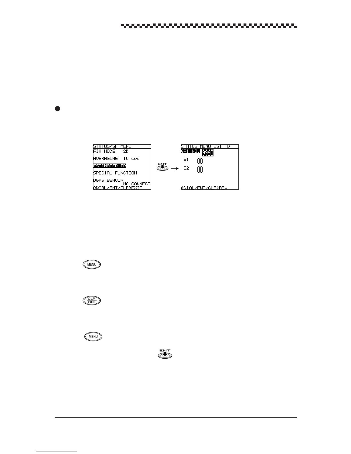
GPS Navigator J-NAV500
4.19.3 TD initializing
The first time the navigator is used or after a master reset, the position display format is set to latitude
and longitude (L/L) and the name of the menu in the [STA TUS/SF MENU] is not [ESTIMATED TD]
but [ESTIMATED L/L] . (See Section 4.19.2, “Initializing, GPS/DGPS receiver”.) Thus set the [TD]
in the [L/L OR TD] menu.
Display Example
[STATUS/SF MENU] [ESTIMATED TD]
(1) The [POSITION] display mode opens after powering up.
(2) Press and select [L/L OR TD] .
(3) Enter [TD] as the [L/L OR TD].
(4) Press to return to the [POSITION] display mode.
(5) The [STATUS] display mode opens.
(6) Press to select [STATUS/SF MENU ] .
(7) Select [ESTIMATED TD] and press .
(8) Enter the relevant GRI NO.
(9) Enter S1 and S2 Enter the two most significant TD digits in S1 and S2.
60
Page 62

4.19.4 Setting DGPS beacon
The frequency and Baud rate of the received beacon station can be set.
Display example
[STATUS/SF Menu] display mode [STATUS/SF MENU DGPS] display mode
(1) Press in the [STATUS] display mode.
This action displays the [ST ATUS/SF MENU] .
GPS Navigator J-NAV500
(2) Turn to select [DGPS Beacon] and press .
When a DGPS beacon receiver or DGPS receiver (DGPS200) is not connected, the message [No
CONNECT].
(3) Setting Receive mode
Turn to select mode and press .
When [
Auto
] is selected, the display return to [ST ATUS/SF Menu].
(4) Enter the frequency and Baud rate.
When [
Manual
] is set, enter the values in [FREQUENCY] and [BAUD RATE].
61
Page 63

GPS Navigator J-NAV500
4.20 Setting Data Output and transmit memory data
CAUTION
When a PC (Personal Computer) is connected to this unit, the output level must be
set to TTL when data is input from the PC since an RS-422 setting could damage the
PC and this unit.
Data transmissions with external equipment can be performed using the data input and output connections of the power cable.
• Output level
The output level when data is exchanged with external equipment (NMEA0183 data output,
memory I/O) can be set to TTL or RS-422.
The output level must be set before data is exchanged with external equipment.
The following two types of data are supported in communications with external equipment.
• Output data
GPS data conforming to the NMEA183 format and navigation data (version 1.5/2.1 switching
function) are output (For details, see Appendix C, “NMEA0183 Output Sentence and Data
Format.”)
• Memory data I/O
The J-NAV500 is to transfer the waypoint and route memory contents of the internal memory to
external equipment and to re-load the memory from the equipment. (See Appendix D, “W aypoint/
Route Plan Data In/Output.”)
Display example
[STATUS S/F MENU] display mode [Special Function] display mode [Special Function Data Output] display mode
62
[Special Function Memory In/Out] display Mode
Page 64

1. Output level setting
(1) Press in the [ST ATUS] display mode.
This action displays the [STA TUS/SF MENU] .
(2) Turn to select [SPECIAL FUNCTION] and press .
The [SF MENU] display mode appears.
(3) Turn to select [DATA OUTPUT] and press .
The [SF MENU DATA OUTPUT] display mode appears.
(4) Turn to select [OUTPUT LEVEL] and press .
GPS Navigator J-NAV500
(5) Set [OUTPUT LEVEL] (
2. Output data setting
(1) Press in the [STATUS] display mode.
This action displays the [STA TUS/SF MENU] .
(2) Turn to select [SPECIAL FUNCTION] and press .
The [SF MENU] display mode appears.
(3) Turn to select [DATA OUTPUT] and press .
The [SF MENU DATA OUTPUT] display mode appears.
(4) Turn to select [NMEA0183] and press .
(5) Set the version of NMEA0183 (
3. Transmitting Memory Data
(1) Press in the [STATUS] display mode.
This action displays the [STA TUS/SF MENU] .
(2) Turn to select [SPECIAL FUNCTION] and press .
The [SPECIAL FUNCTION] display mode appears.
RS-422/TTL
1.5
(default)
(default))
/2.1
).
(3) Turn to select [MEMORY IN/OUT] and press .
This displays the [SPECIAL FUNCTION MEMORY IN/OUT] display mode.
(4) Memory Data Output
Waypoint and route plan data can be uploaded separately to external equipment such as a PC.
This data can be saved and edited on external equipment.
During the upload the message [UPLOADING] is displayed. The time required for the transfer
depends on the amount of data transferred.
• Waypoint data output
Select [OUTPUT WPT DATA] and press .
• Route plan data output
Select [OUTPUT ROUTE DATA] and press .
63
Page 65

GPS Navigator J-NAV500
(5) Memory data input
W aypoint and route plan data can be downloaded separately from external equipment such as a
PC.
During the download the message [DOWNLOADING] is displayed. When the message
ÒDOWNLOADINGÓ is displayed, inputs are received from external equipment. The time
required for the transfer depends on the amount of data transferred.
• Waypoint data input
Select [INPUT WPT DATA] and press .
• Route plan data input
Select [INPUT ROUTE DATA] and press .
The transfer rate is one memory per second.
4.21 Displaying the Simulator Mode
The simulator function allows you to view approaches to waypoints and following route plans on the
various navigation displays when the ship is not actually moving.
Display example
[STATUS/SF MENU] display mode [SF MENU] display mode
(1) Press in the [STATUS] display mode.
(2) Turn to select [SPECIAL FUNCTION] and press .
The [SPECIAL FUNCTION] display mode appears.
(3) Turn to select [SIMULA TOR] and press .
(4) Set to on or
The [SIM] indicator goes on when the simulator is on. Actual navigation cannot be performed during
simulation. The simulator must be turned off before navigation.
off
(default value).
64
Page 66

GPS Navigator J-NAV500
4.22 Performing Master Reset
• A master reset clears registered date. Use this function with care.
• When resetting the navigator, perform Initializing GPS/DGPS receiver as described in section
4.19.2 when correcting for local time.
There are a soft and hard reset functions. A soft reset clears all data except waypoint and route plan
data. Thus items set or selected through operation are all returned to their default values. A hard reset
clears all data including waypoints and route plans.
Display example
[STATUS/SF Menu] display mode [SF Menu] display mode
(1) Press in the [STATUS] display mode.
This action displays the [STA TUS/SF MENU] .
(2) Turn to select [SPECIAL FUNCTION] and press .
The [SPECIAL FUNCTION] display mode appears.
(3) Turn to select [MASTER RESET] and press .
(4) Select soft or hard reset and press .
A
soft
or
hard
reset is performed.
65
Page 67

GPS Navigator J-NAV500
5. Maintenance and Inspection
WARNING
The user must not perform internal inspections or repairs. Inspections and repairs
carried out by unauthorized personnel can cause fire or electric shock. Refer such
repairs and inspections to subsidiaries, branch offices sales departments or representatives of Japan Radio Co., Ltd.
CAUTION
Use designated fuses. Use of other fuses may cause fire or breakdown.
Model:MF60NR-2A
Do not use other than designated batteries as this could lead to breakdown or malfunction. The navigator is equipped with a lithium battery to back up RAM in the event
of a power outage. The life of the battery is more than five years. However, to ensure
proper operation of the receiver, replace it before it has been completely depleted. Let
JRC, our agents or dealers replace the battery for you when it is time to replace it.
Lithium battery
Model:CR2032-THD JRC code:5ZBBJ00006
Daily maintenance and inspections will keep your navigator in good working order and prolong its
service life. Perform the following simple inspections before going to use and when occurring unit
trouble.
Is the unit properly secured or is it loose? Secure as necessary.
Are the connecting cables loose? Connect them firmly.
Is the fuse blown? Replace with a designated fuse.
Is the unit damaged? If the unit is not operating properly , have it
serviced by our agent or your dealer.
Are any of the connecting cables damaged. Damaged cables could cause electric shock,
fire or equipment damage. Do not continue
using under such conditions but take it to our
agent or your dealer for service.
66
Page 68

GPS Navigator J-NAV500
6. After-sales Service
When asking for service
When you think the navigator is not operating normally, consult your dealer, our agent, branch, sales
department or subsidiary for advice.
Repair during warranty period
Should a malfunction occur when the navigator has been operated according to descriptions and
instructions in the instruction manual, it will be repaired free of charge. However, breakdowns
resulting from abuse, negligence, natural disaster, fire or other unforeseeable incident will be
charged.
Repair after warranty period
Repairs that restore normal operation made after the warranty period have to be paid in full by the
client.
Product data that should be provided when you ask for service
Name of product, model and serial number
Description of malfunction (as detailed as possible)
Company address or name of organization, address and telephone number
Checks and inspection
Product performance gradually declines with long use resulting in inaccurate measurements, although
the rate of this decline varies with frequency of use. To prevent this, periodic maintenance is required
in addition to regular inspections. For information on maintenance, contact your dealer. Note that
maintenance is charged for .
Inquiries should be directed to JRC. Addresses and telephone numbers are listed on the back cover of
this manual.
67
Page 69

GPS Navigator J-NAV500
7. Disposal
WARNING
Before you dispose of a lithium battery , place a piece of adhesive tape across the plus
an minus terminals to prevent electric shorts that could result in fire, explosions or
other hazards.
7.1 Disposal of Navigator
Observe all national laws and regulations when you dispose of the navigator.
7.2 Handling Used Lithium Batteries
The navigator contains a lithium battery for battery backup.
Dispose of used lithium batteries as non-combustible garbage.
Insulate the + and - terminals by placing a piece of adhesive tape over them before disposal.
Observe all local regulations concerning the disposal of batteries.
For details, consult your dealer, our agent or sales department, or local authority.
68
Page 70

GPS Navigator J-NAV500
8. Specifications
Display
LCD Blue (neutral mode) STN type
Dot Materix: 128 x 100 dots
Size: 79 mm W x 61 mm H
LCD contrast adjustment Automatic adjustment by using temperature sensor and manual
adjust
Backlighting EL panel for LCD, LED for key switches
Brightness adjustment 2 step keyboard setting, high/low
Key switches 9 including 1 rotary encoder
Waypoints Max. 499
Entered as latitude/longitude, time difference or bearing/distance data
Route plans 20 plans, 199 waypoints max
Event Marks Max. 499 including waypoint memory
ShipÕs Track Max. 499 point memory
Position correction Automatic (46 geodetic systems registered)/manual
Alarms Waypoint arrival, anchor, off-course, No fix, non-connected
state, HDOP
Magnetic compass correction Automatic or manual correction
Unit Distance/speed: NM/KTS, SM/MPH, KM/PH (selectable)
Current position: 0.001Õ min
Plot function Scale: 0.125 nm to 100 nm
Track interval: 0.5, 1, 3, 5, 10 min, 0.2, 0.5 nm, OFF
GPS function Averaging: 1 to 99 sec settable (default value: 10 sec)
position fix mode: 2D/auto
Special functions •MOB function
• Simulator function (indicated as SIM)
•Loran C time difference
• 7 languages (English, German, Norwegian, French,
Spanish, Japanese, Italian)
•DGPS alarm
• Upload/download function of waypoint/route data
Data output • Output level: RS-422, TTL selectable
• NMEA0183 (version 1.5/2.1 selectable)
• Output sentences: GLL, VTG, APB, BWC, GGA, RMC, RMB
69
Page 71

GPS Navigator J-NAV500
Memory backup Internal lithium battery
Power supply Input voltage: 12 VDC (10.8 to 16.0 VDC)
Power consumption: 6 W or less (with GPS/DGPS receiver)
OWeight less than 0.9kg.
Operating environment Ð15 C to +55 C
Storage environment Ð40 C to +80 C
Operating humidity +40 C, 93%
70
Page 72

GPS Navigator J-NAV500
Appendices
Appendix A Message list
Error messages
Message Description
RAM NG Display RAM failure. Contact JRC sales department or local branch.
ROM NG Display ROM failure. Contact JRC sales department or local branch.
RCV NG GPS/DGPS receiver is not connected or is malfunctioning.
Connect GPS/DGPS receiver properly. If the message still persists, contact
JRC sales department or local branch.
Alarms
Message Description
ARV Arrival alarm. The ship has come inside set arrival range.
Press to silence alarm. The display goes blank when the distance is set
to 0.00 m.
ANC Anchor alarm. The ship has drifted outside the set distance range.
Press to silence alarm. The display goes blank when the distance is set
to 0.00 m.
XTE Off-course alarm. The ship has drifted more than the set distance off course.
Press to silence alarm. The display goes blank when the distance is set
to 0.00 m.
HDOP Indicates poor HDOP value. The HDOP indicator flashes when HDOP ex-
ceeds 4. Since HDOP is poor, GPS and DGPS receiver position accuracy is
poor. The alarm goes of f when HDOP improves.
NO FIX GPS or DGPS receiver is not position fixing. Press to silence alarm.
Install GPS or DGPS receiver in location with better reception.
GPS DGPS alarm. When a DGPS alarm is set to on and the GPS or DGPS receiver
goes from DGPS to GPS position fixing, the buzzer sounds once.
MOB MOB function (displayed in the title area). The MOB function is
canceled when MOB is pressed for 3 seconds or longer.
71
Page 73

GPS Navigator J-NAV500
Operation messages
Message Description
EVENT FULL Too many events (waypoints) registered. This message is displayed when an
attempt is made registered a new event.
Delete old data before making new registration.
WPT FULL
Too many waypoints registered. Delete old data before making new registration.
This message is displayed when an attempt is made to set a waypoint by entering positions, bearings or distance.
NO W AYPOINT No waypoint has been registered.
Register a waypoint.
ROUTE FULL T oo many routes registered. Delete old data before making new registration.
NO ROUTE No route has been registered.
Register a route.
NOW USING,
IN ROUTE,
A registered waypoint number has been specified in the registration of an event.
Register the event in a free waypoint number.
DEST PT
ARE YOU SURE?
ENT
Confirmation message asking if a waypoint or route plan should be deleted.
Press to delete. To cancel deletion, press .
CALCULATING The program is calculating distance or position of waypoint or route plan.
Please wait.
DOWNLOADING
The unit is downloading data from external equipment. Please wait.
UPLOADING The unit is uploading data to external equipment. Please wait.
SIM The simulator mode is on. To exit simulator mode, turn it off.
WPT NO DEST No waypoint was set in a route plan or in direct route.
72
Page 74

Appendix B Geodetic System Table
The navigator displays the names of geodetic system 1 to 9, but only the numbers are given for
datums 11 and beyond. Tables 1 and 2 list all the 46 geodetic system that are used.
Table 1
GPS Navigator J-NAV500
73
Page 75

GPS Navigator J-NAV500
Geodetic system 11 to 47
Table 2
74
Page 76

GPS Navigator J-NAV500
Appendix C NMEA0183 output sentence and data format
1. Output sentences
RMC : Recommended Minimum Specific GPS/T ransit Data.
RMB : Recommended Minimum Navigation Information.
APB : Autopilot Sentence “B”.
BWC : Bearing & Distance to Waypoint.
GLL : Geographic position - Latitude/Longitude,
GGA : Global Position System Fix data.
VTG : Course Over Ground and Ground Speed.
2. Output timing
GGA/RMC/RMB/GLL : 2 seconds interval
APB/BWC/VTG : 2 seconds interval
3. Serial format
Baud rate : 4800 bps
Data bits : 8 bits
Parity : None
Start bit : 1 bit
Stop bit : 1 bit
4. Data format
<Version 1.5>
RMC sentences
$GPRMC,hhmmss,A,ddmm.mm,a,dddmm.mm,a,xx.x,xxx,xxxxxx,xx,a*hh<CR><LF>
1 2 3 4 5 6 7 8 9 10 11 12
1 : UTC of position fix (Hour, Minute, Second)
2 : Data status A: valid V: invalid
3, 4 : Latitude (Degree, Minute), N/S
5, 6 : Longitude (Degree, Minute), E/W
7 : Speed over ground (knot)
8 : Course over ground, degrees True
9 : Date : Day, Month, Year (UTC)
10, 11 : Magnetic variation, E/W
12 : Checksum
75
Page 77

GPS Navigator J-NAV500
RMB sentences
$GPRMB,A,x.xx,a,cccc,cccc,llll.ll,a,yyyyy .yy,a,xxx.x,xxx,uxx.x,A*hh<CR><LF>
1 2 3 4 5 6 7 8 9 10 11 12 13 14
1 : Data status A: valid V: invalid
2 : Cross track error (NM)
3 : Direction to steer L = left, R = right
4 : Origin waypoint ID
5 : Destination waypoint ID
6, 7 : Destination waypoint latitude, N/S
8, 9 : Destination waypoint longitude, E/W
10 : Range to destination (NM)
11 : Bearing to destination, degree true
12 : Destination closing velocity (knot)
13 : Arrival status : A = Arrival circle entered, V = not entered/passed
14 : Checksum
APB sentences
$GP APB,A,,x.xx,a,N,A,,xxx,a,cccc,xxx,a,,<CR><LF>
1 2 3 4 5 6 7 8 9 10
1 : Data status A: valid V: invalid
2 : Magnitude of XTE (cross-track-error)
3 : Direction to steer, L=left, R=right
4 : XTE units (NM)
5 : Arrival status A = Arrival circle entered, V = not entered/passed
6, 7 : Bearing origin to distination, M = Magnetic, T = True
8 : Destination waypoint ID
9, 10 : Bearing, present position to destination, M = Magnetic, T = True
BWC sentences
$GPBWC,hhmmss,llll.ll,a,yyyyy.yy,a,xxx,T,xxx,M,xxx.x,N,cccc<CR><LF>
1 2 3 4 5 6 7 8 9 10 11 12
1 : UTC of observation (Hour, Minute, Second)
2, 3 : W aypoint latitude, N/S
4, 5 : Waypoint longitude, E/W
6, 7 : Bearing, degrees true
8, 9 : Bearing degrees magnetic
10, 11 : Distance (NM)
12 : Waypoint ID
76
Page 78

GPS Navigator J-NAV500
GLL sentences
$GPGLL,ddmm.mm,a,dddmm.mm,a<CR><LF>
1 2 3 4
1, 2 : Latitude (Degree, Minute), N/S
3, 4 : Longitude (Degree, Minute), E/W
GGA sentences
$GPGGA,hhmmss,ddmm.mmm,a,dddmm.mmm,a,x,x,xx,uxxxx,M,,M,,<CR><LF>
1 2 3 4 5 6 7 8 9 10
1 : UTC of position (Hour, Minute, Second)
2, 3 : Latitude (Degree, Minute), N/S
4, 5 : Longitude (Degree, Minute), E/W
6 : GPS quality indicator 0 = GPS No Fix, 1= GPS Fix, 2 = Differential GPS Fix
7 : Number of statellites in use for position fix
8 : Horizontal dilution of precision (HDOP)
9, 10 : Antenna height above/below mean-sea-level (m), u:sign
VTG sentences
$GPVTG,xxx,T,xxx,M,xx.x,N,,<CR><LF>
1 2 3 4 5 6
1, 2 : Course, degree true
3, 4 : Course, degree Magnetic
5, 6 : Speed (knots)
<Version 2.1>
RMC sentences
$GPRMC,hhmmss,A,ddmm.mmm,a,dddmm.mmm,a,xx.x,xxx,xxxxxx,xx,a*hh<CR><LF>
1 2 3 4 5 6 7 8 9 10 11 12
1 : UTC of position fix (Hour, Minute, Second)
2 : Data status A: valid V: invalid
3, 4 : Latitude (Degree, Minute), N/S
5, 6 : Longitude (Degree, Minute), E/W
7 : Speed over ground (knot)
8 : Course over fround, degrees True
9 : Date : Day, Month, Year (UTC)
10, 11 : Magnetic variation, E/W
12 : Checksum
77
Page 79

GPS Navigator J-NAV500
RMB sentences
$GPRMB,A,x.xx,a,cccc,cccc,llll.ll,a,yyyyy .yy,a,xxx.x,xxx,uxx.x,A*hh<CR><LF>
1 2 3 4 5 6 7 8 9 10 11 12 13 14
1 : Data status A: valid V: invalid
2 : Cross track error (NM)
3 : Direction to steer L = left, R = right
4 : Origin waypoint ID
5 : Destination waypoint ID
6, 7 : Destination waypoint latitude, N/S
8, 9 : Destination waypoint latitude, E/W
10 : Range to destination (NM)
11 : Bearing to destination, degree true
12 : Destination closing velocity (knot)
13 : Arrival status : A = Arrival circle entered, V = not entered/passed
14 : Checksum
APB sentences
$GP APB,A,,x.xx,a,N,A,,xxx,a,cccc,xxx,a,,*hh<CR><LF>
1 2 3 4 5 6 7 8 9 10 11
1 : Data status A: valid V: invalid
2 : Magnitude of XTE (cross-track-error)
3 : Direction to steer, L=left, R=right
4 : XTE units (NM)
5 : Arrival status A = Arrival circle entered, V = not entered/passed
6, 7 : Bearing origin to distination, M = Magnetic, T = True
8 : Destination waypoint ID
9, 10 : Bearing, present position to destination, M = Magnetic, T = True
11 : Checksum
BWC sentences
$GPBWC,hhmmss,llll.ll,a,yyyyy.yy,a,xxx,T,xxx,M,xxx.x,N,cccc*hh<CR><LF>
1 2 3 4 5 6 7 8 9 10 11 12 13
1 : UTC of observation (Hour, Minute, Second)
2, 3 : W aypoint latitude, N/S
4, 5 : Waypoint longitude, E/W
6, 7 : Bearing, degrees true
8, 9 : Bearing, degrees magnetic
10, 11 : Distance (NM)
12 : Waypoint ID
13 : Checksum
78
Page 80

GPS Navigator J-NAV500
GLL sentences
$GPGLL,ddmm.mmm,a,dddmm.mmm,a,hhmmss,A*hh<CR><LF>
1 2 3 4 5 6 7
1, 2 : Latitude ((Degree, Minute), N/S
3, 4 : Longitude (Degree, Minute), E/W
5 : UTC of position (Hour, minute, Second)
6 : Data status A: valid, V: invalid
7 : Checksum
GGA sentences
$GPGGA,hhmmss,ddmm.mmm,a,dddmm.mmm,a,x,x,xx,uxxxx,M,,M,,*hh<CR><LF>
1 2 3 4 5 6 7 8 9 10 11
1 : UTC of position (Hour, Minute, Second)
2, 3 : Latitude ((Degree, Minute), N/S
4, 5 : Longitude (Degree, Minute), E/W
6 : GPS quality indicator 0 = GPS No Fix, 1= GPS Fix, 2 = Differential GPS Fix
7 : Number of statellites in use for position fix
8 : Horizontal dilution of precision (HDOP)
9, 10 : Antenna height above/below mean-sea-level (m), u:sign
11 : Checksum
VTG sentences
$GPVTG,xxx,T,xxx,M,xx.x,N,,*hh<CR><LF>
1 2 3 4 5 6 7
1, 2 : Course, degree true
3, 4 : Course, degree Magnetic
5, 6 : Speed (knots)
7 : Checksum
79
Page 81

GPS Navigator J-NAV500
Appendix D Waypoint/Route Plan Data In/Output
Serial format
Baud rate : 4800 bps
Data bits : 8 bits
Parity : None
Start bit : 1 bit
Stop bit : 1 bit
Waypoint data I/O
$PJWPL,llll.lll,a,yyyyy.yyy,a,ccc*hh
1 2 3 4 5 6
1, 2 : Latitude ( , minute)
3, 4 : Longitude ( , minute)
5 : Waypoint number
6 : Checksum
Example : $PJWPL,3543.501,N,13934.020,E,001*7D
$PJWPL,3543.324,N,13933.786,E,002*7O
:
:
Route plan data I/O
$PJRTE,xxx,xxx,a,ccc,ccc,------------------,ccc*hh
1 2 3 4 5 5 6
1 : Total number of ROUTE messages
2 : ROUTE message serial number
3 : Message mode C
4 : Route plan number
5 : Waypoint number of route plan
6 : Checksum
Example :
$PJR TE,003,001,C,001,001,002,003,004,005,006,007,008,009,010,011,012,013,014*2E
$PJRTE,003,002,C,001,015,016,017,018,019,020,021,022,023,024,025,026,027,028*27
$PJRTE,003,003,C,001,029,030,031,032,033,034,035,036,037,038*28
$PJRTE,001,001,C,002,001,005,007*37
:
:
80
Page 82

Appendix E Waypoint List
Waypoint no. Waypoint name Remarks
GPS Navigator J-NAV500
81
Page 83

GPS Navigator J-NAV500
Waypoint no. Waypoint name Remarks
82
Page 84

Page 85

 Loading...