

JRC JMA-9132-SA, JMA-9123-9XA, JMA-9122-6XA, JMA-9122-6XAH, JMA-9110-6XAH Installation Manual
...Page 1

JMA-9133-SAJMA-9133-SA
JMA-9132-SAJMA-9132-SA
JMA-9123-7XA/9XAJMA-9123-7XA/9XA
JMA-9122-6XA/9XA/6XAHJMA-9122-6XA/9XA/6XAH
JMA-9110-6XA/6XAHJMA-9110-6XA/6XAH
JMA-7133-SAJMA-7133-SA
JMA-7132-SAJMA-7132-SA
JMA-7123-7XA/9XAJMA-7123-7XA/9XA
JMA-7122-6XA/9XA/6XAHJMA-7122-6XA/9XA/6XAH
JMA-7110-6XA/6XAHJMA-7110-6XA/6XAH
MARINE RADARMARINE RADAR
EQUIPMENTEQUIPMENT
INSTALLATIONINSTALLATION
MANUALMANUAL
Page 2

Page 3

Index
Cross Reference
JMA-9133-SA ...........................................................................................................i
JMA-9132-SA ..........................................................................................................ii
JMA-9123-7XA/9XA ...............................................................................................iii
JMA-9122-6XA/9XA ...............................................................................................iv
JMA-9122-6XAH .....................................................................................................v
JMA-9110-6XA/6XAH ............................................................................................vi
JMA-7133-SA ........................................................................................................vii
JMA-7132-SA .......................................................................................................viii
JMA-7123-7XA9XA ................................................................................................ix
JMA-7122-6XA/9XA ................................................................................................x
JMA-7122-6XAH ....................................................................................................xi
JMA-7110-6XA/6XAH ...........................................................................................xii
SECTION 1
EQUIPMENT COMPOSITION
1.1 GENERAL COMPOSITION ....................................................................1-1
1.1.1 JMA-9100 SERIES RADAR ....................................................................... 1-1
1.1.2 JMA-7100 SERIES RADAR ....................................................................... 1-2
1.2 LIST OF CIRCUITS ................................................................................1-4
1.2.1 JMA-9100 SERIES RADAR ....................................................................... 1-4
1.2.2 JMA-7100 SERIES RADAR ..................................................................... 1-11
SECTION 2
INSTALLATION OF SCANNER UNIT
2.1 EQUIPMENT CABLE .............................................................................2-1
2.1.1 CFQ-6912-** ...............................................................................................2-1
2.1.2 2695110056 ................................................................................................2-2
2.1.3 2695111153 ................................................................................................2-3
2.1.4 Cable end processing method .................................................................2-4
2.1.5 Connection to the display-unit side terminal block ............................... 2-7
2.2 INSTALLATION OF SCANNER UNIT ....................................................2-8
2.2.1 NKE-2103 type scanner ............................................................................ 2-8
2.2.2 NKE-2254 type scanner .......................................................................... 2-11
2.2.3 NKE-1125 type scanner .......................................................................... 2-13
2.2.4 NKE-1129 type scanner .......................................................................... 2-15
2.2.5 NKE-1130 type scanner .......................................................................... 2-17
2.2.6 NKE-1139 type scanner .......................................................................... 2-19
2.3 INSTALLATION OF TRANSMITTER RECEIVER UNIT ......................2-21
2.3.1 NTG-3225 type transmitter receiver ......................................................2-21
2.3.2 NTG-3230 type transmitter receiver ......................................................2-24
2.4 PRECAUTIONS ....................................................................................2-26
2.4.1 Installation of scanner unit .................................................................... 2-26
2.4.2 Routing coaxial cable and flexible waveguide ..................................... 2-29
2.4.3 Scanner installation position .................................................................2-31
Page 4

2.4.4 Confirmation during test run .................................................................2-35
2.4.5 Others .......................................................................................................2-35
SECTION 3
INSTALLATION OF DISPLAY UNIT
3.1 INSTALLATION OF DISPLAY UNIT ......................................................3-1
3.1.1 Exterior Drawing of NCD-4990 .................................................................3-2
3.1.2 Exterior drawing of NCD-4990T ............................................................... 3-3
3.1.3 Exterior drawing of NCD-4790 ................................................................. 3-6
3.1.4 Exterior drawing of NCD-4790T ............................................................... 3-7
3.2 INSTALLATION OF AC-DC CONVERTER NBA-5135 ........................3-10
3.2.1 NBA-5135 Packing List ........................................................................... 3-10
3.2.2 Exterior drawing of NBA-5135 ............................................................... 3-12
3.2.3 NCD-4990 .................................................................................................3-13
3.2.4 NCD-4990T ...............................................................................................3-17
3.2.5 NCD-4790 .................................................................................................3-18
3.2.6 NCD-4790T ...............................................................................................3-20
3.3 CONNECTIONS WITH SCANNER AND TRANSCEIVER ...................3-21
3.3.1 Connections with NKE-1125,NTG-3225,NKE-1130,NTG-3230 ............. 3-21
3.3.2 Connections with NKE-2103,NKE-2254 ................................................. 3-22
3.4 CONNECTION WITH GPS ...................................................................3-24
3.5 CONNECTIONS WITH VESSEL SPEED UNIT (2-AXIS LOG) ............3-26
3.6 CONNECTIONS WITH GYRO AND ELECTROMAGNETIC LOG ......3-27
3.7 CONNECTION WITH GYRO (IEC61162-1/2) .......................................3-29
3.8 CONNECTIONS WITH AIS ..................................................................3-31
3.9 CONNECTIONS WITH ECDIS .............................................................3-33
3.9.1 Transmission Port Setting (TX Port) ..................................................... 3-34
3.10 CONNECTION WITH ALARM MONITORING SYSTEM .....................3-36
3.11 EXAMPLE OF WIRING IN THE DEVICE .............................................3-38
3.12 DISPLAY UNIT LEDS FOR VARIOUS SIGNALS ................................3-39
3.12.1 Serial Signal ............................................................................................. 3-40
3.12.2 Power supply status ............................................................................... 3-41
3.12.3 Alarm Signal ........................................................................................... 3-42
3.12.4 Fan Alarm ................................................................................................. 3-43
SECTION 4
INITIAL SETTING
4.1 GYRO INTERFACE SETTING ...............................................................4-2
4.1.1 GYRO INPUT SETTING (STEP/SYNC setting) ......................................... 4-2
4.1.2 NMEA Input setting ...................................................................................4-5
4.2 TUNE ADJUSTMENT .............................................................................4-7
4.3 BEARING ADJUSTMENT ......................................................................4-8
4.4 RANGE ADJUSTMENT ..........................................................................4-9
4.5 NAVIGATOR SETTING ........................................................................4-10
4.6 TRUE BEARING SETTING ..................................................................4-11
4.7 ANTENNA HEIGHT SETTING .............................................................4-12
Page 5

4.8 CCRP SETTING ...................................................................................4-13
4.9 MAIN BANG SUPPRESSION SETTING ..............................................4-14
4.10 PERFORMANCE MONITOR SETTING ...............................................4-16
4.11 DATE/TIME DISPLAY SETTING ..........................................................4-18
4.12 INITIALIZATION OF SCANNER OPERATION TIME ...........................4-20
SECTION 5
OPTION UNIT
5.1 INSTALLATION OF INTERSWITCH UNIT ............................................5-1
5.1.1 Equipment cable end processing ............................................................5-1
5.1.2 Plug terminal block connection procedures .......................................... 5-2
5.1.3 Installation of interswitch unit ................................................................. 5-3
5.1.4 Setting ........................................................................................................ 5-7
5.1.5 Confirmation after installation ...............................................................5-11
5.1.6 Inter-board connection diagram ............................................................5-12
5.2 INSTALLATION OF POWER CONTROL UNIT ...................................5-14
5.2.1 Connection with NKE-2103 type and NKE-2254-6HS type scanners ..5-14
5.2.2 Connections to NKE-1125, NTG-3225, NKE-1130, and NTG-3230 ......5-16
5.2.3 Equipment cable end processing ..........................................................5-16
5.2.4 End processing of each cable core .......................................................5-16
5.2.5 Connection to display unit .....................................................................5-16
5.2.6 General system diagram of power control unit (JMA-7100) ..............5-18
5.2.7 General system diagram of power control unit (JMA-9100) ..............5-36
5.2.8 Inter-board connection diagram of power control unit ....................... 5-54
5.2.9 Exterior drawing of Power Control Unit ................................................5-60
5.3 INSTALLATION OF VDR .....................................................................5-62
5.3.1 Connections ............................................................................................ 5-62
5.3.2 VDR I/F kit ................................................................................................ 5-63
5.4 INSTALLATION OF SUB-OPERATION UNIT AND EXPANSION OF
TRACKBALL 5-64
5.4.1 Sub Operation Unit ................................................................................. 5-64
5.4.2 Expansion of trackball ............................................................................ 5-65
SECTION 6
Appendix
6.1 EXTERIOR DRAWING ...........................................................................6-1
6.1.1 NKE-1139 ...................................................................................................6-1
6.1.2 NTG-3230 .................................................................................................. 6-3
6.1.3 NKE-1130 .................................................................................................. 6-4
6.1.4 NKE-1129-7 ................................................................................................6-5
6.1.5 NKE-1129-9 ................................................................................................6-6
6.1.6 NTG-3225 ...................................................................................................6-7
6.1.7 NKE-1125-6 ................................................................................................6-8
6.1.8 NKE-1125-9 ................................................................................................6-9
6.1.9 NKE-2254-6HS .........................................................................................6-10
6.1.10 NKE-2103-6/NKE-2103-6HS ....................................................................6-11
6.1.11 NCD-4990 .................................................................................................6-12
6.1.12 NDC-1399-9 ..............................................................................................6-13
6.1.13 NCE-5163 .................................................................................................6-14
6.1.14 NWZ-170 ................................................................................................... 6-15
6.1.15 NCD-4790 .................................................................................................6-16
6.1.16 NDC-1399-7 ..............................................................................................6-17
6.1.17 NCE-5163 .................................................................................................6-18
Page 6

6.1.18 NWZ-173 ..................................................................................................6-19
6.2 GENERAL SYSTEM DIAGRAM ...........................................................6-20
6.2.1 General system diagram of JMA-7100 (Self-standing type) ................ 6-20
6.2.1.1 General system diagram of JMA-7132-SA (Self-standing)................... 6-21
6.2.1.2 General system diagram of JMA-7133-SA (Self-standing).................. 6-22
6.2.1.3 General system diagram of JMA-7122-6XA (Self-standing)................. 6-23
6.2.1.4 General system diagram of JMA-7122-9XA (Self-standing)................. 6-24
6.2.1.5 General system diagram of JMA-7122-6XAH (Self-standing) .............. 6-25
6.2.1.6 General system diagram of JMA-7123-7XA (Self-standing)................. 6-26
6.2.1.7 General system diagram of JMA-7123-9XA (Self-standing)................. 6-27
6.2.1.8 General system diagram of JMA-7110-6XA (Self-standing)................. 6-28
6.2.1.9 General system diagram of JMA-7110-6XAH (Self-standing) .............. 6-29
6.2.2 General system diagram of JMA-7100 (Desktop type) ........................ 6-30
6.2.2.1 General system diagram of JMA-7132-SA (Desktop) ..........................6-31
6.2.2.2 General system diagram of JMA-7133-SA (Desktop) ..........................6-32
6.2.2.3 General system diagram of JMA-7122-6XA (Desktop) ........................6-33
6.2.2.4 General system diagram of JMA-7122-9XA (Desktop) ........................6-34
6.2.2.5 General system diagram of JMA-7122-6XAH (Desktop)...................... 6-35
6.2.2.6 General system diagram of JMA-7123-7XA (Desktop) ........................6-36
6.2.2.7 General system diagram of JMA-7123-9XA (Desktop) ........................6-37
6.2.2.8 General system diagram of JMA-7110-6XA (Desktop) ........................6-38
6.2.2.9 General system diagram of JMA-7110-6XAH (Desktop)...................... 6-39
6.2.3 General system diagram of JMA-9100 (Self-standing type) ................ 6-40
6.2.3.1 General system diagram of JMA-9132-SA (Self-standing) ................... 6-41
6.2.3.2 General system diagram of JMA-9133-SA (Self-standing)................... 6-42
6.2.3.3 General system diagram of JMA-9122-6XA (Self-standing)................. 6-43
6.2.3.4 General system diagram of JMA-9122-9XA (Self-standing)................. 6-44
6.2.3.5 General system diagram of JMA-9122-6XAH (Self-standing) .............. 6-45
6.2.3.6 General system diagram of JMA-9123-7XA (Self-standing)................. 6-46
6.2.3.7 General system diagram of JMA-9123-9XA (Self-standing)................. 6-47
6.2.3.8 General system diagram of JMA-9110-6XA (Self-standing)................. 6-48
6.2.3.9 General system diagram of JMA-9110-6XAH (Self-standing) .............. 6-49
6.2.4 General system diagram of JMA-9100 (Desktop type) ........................ 6-50
6.2.4.1 General system diagram of JMA-9132-SA (Desktop) .........................6-51
6.2.4.2 General system diagram of JMA-9133-SA (Desktop) ..........................6-52
6.2.4.3 General system diagram of JMA-9122-6XA (Desktop) ........................6-53
6.2.4.4 General system diagram of JMA-9122-9XA (Desktop) ........................6-54
6.2.4.5 General system diagram of JMA-9122-6XAH (Desktop)...................... 6-55
6.2.4.6 General system diagram of JMA-9123-7XA (Desktop) ........................6-56
6.2.4.7 General system diagram of JMA-9123-9XA (Desktop) ........................6-57
6.2.4.8 General system diagram of JMA-9110-6XA (Desktop) ........................6-58
6.2.4.9 General system diagram of JMA-9110-6XAH (Desktop)...................... 6-59
6.3 INTER-BOARD CONNECTION DIAGRAM ..........................................6-60
6.3.1 Inter-board connection diagram of JMA-7100 ...................................... 6-60
6.3.1.1 Inter-board connection diagram of JMA-7132-SA ................................ 6-61
6.3.1.2 Inter-board connection diagram of JMA-7133-SA ................................ 6-62
6.3.1.3 Inter-board connection diagram of JMA-7122-6XA/9XA ...................... 6-63
6.3.1.4 Inter-board connection diagram of JMA-7122-6XAH............................ 6-64
6.3.1.5 Inter-board connection diagram of JMA-7122-6XAH(Desktop) ............ 6-65
6.3.1.6 Inter-board connection diagram of JMA-7123-7XA/9XA ......................6-66
6.3.1.7 Inter-board connection diagram of JMA-7110-6XA/6XAH....................6-67
6.3.1.8 Inter-board connection diagram of JMA-7110-6XA/6XAH(Desktop) .... 6-68
6.3.1.9 Inter-unit connection diagram of NCD-4790T....................................... 6-69
Page 7

6.3.2 Inter-board connection diagram of JMA-9100 ...................................... 6-70
6.3.2.1 Inter-board connection diagram of JMA-9132-SA ................................. 6-71
6.3.2.2 Inter-board connection diagram of JMA-9133-SA ................................ 6-72
6.3.2.3 Inter-board connection diagram of JMA-9122-6XA/9XA ...................... 6-73
6.3.2.4 Inter-board connection diagram of JMA-9122-6XAH............................ 6-74
6.3.2.5 Inter-board connection diagram of JMA-9122-6XAH (Desktop) ........... 6-75
6.3.2.6 Inter-board connection diagram of JMA-9123-7XA/9XA ...................... 6-76
6.3.2.7 Inter-board connection diagram of JMA-9110-6XA/6XAH....................6-77
6.3.2.8 Inter-board connection diagram of JMA-9110-6XA/6XAH (Desktop) ... 6-78
6.3.2.9 Inter-unit connection diagram of NCD-4990T......................................6-79
6.4 SCANNER UNIT INTERCONNECTION ...............................................6-80
6.4.1 NKE-2103 ................................................................................................ 6-81
6.4.2 NKE-2254 ................................................................................................ 6-82
6.4.3 NKE-1125 (AC110V) ................................................................................ 6-83
6.4.4 NKE-1125 (AC220V) ................................................................................ 6-84
6.4.5 NKE-1129 (AC110V) ................................................................................ 6-85
6.4.6 NKE-1129 (AC220V) ................................................................................ 6-86
6.4.7 NTG-3225 .................................................................................................6-87
6.4.8 NKE-1130 (AC110V) ................................................................................ 6-88
6.4.9 NKE-1130 (AC220V) ................................................................................ 6-89
6.4.10 NKE-1139 (AC110V) ................................................................................ 6-90
6.4.11 NKE-1139 (AC220V) ................................................................................ 6-91
6.4.12 NTG-3230 .................................................................................................6-92
Page 8

Page 9

Cross Reference
Cross Reference
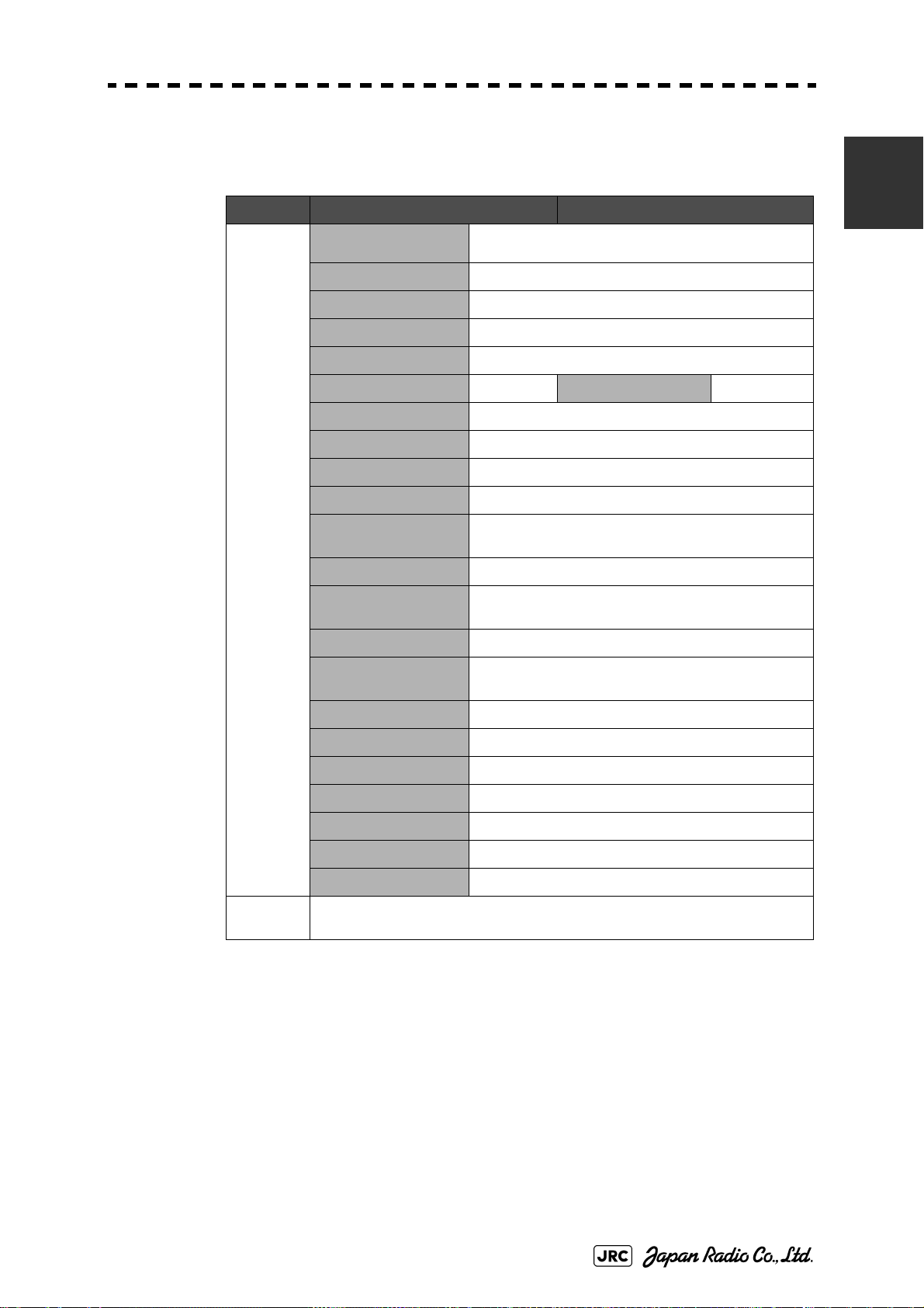
JMA-9133-SA
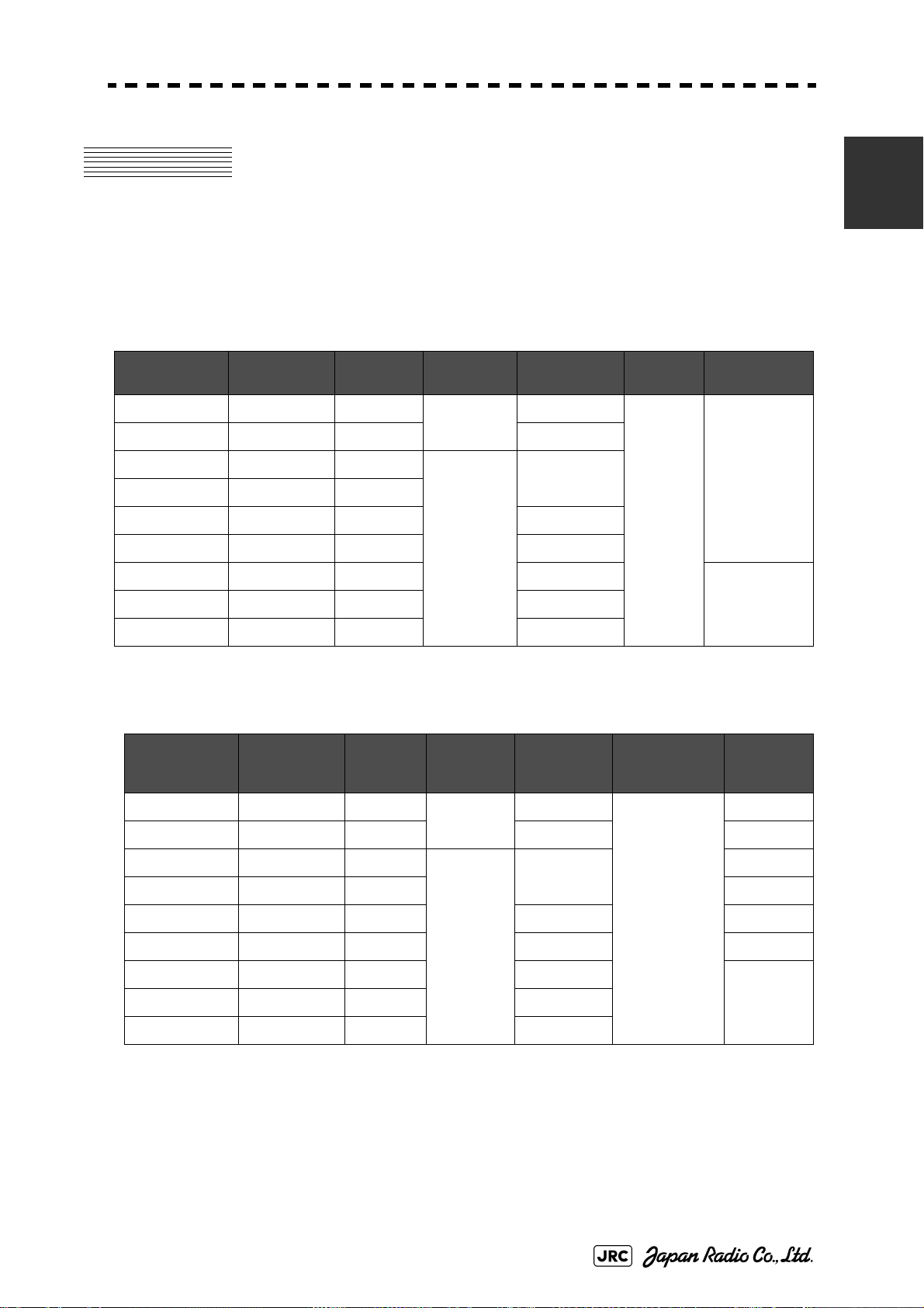
Tab le 1- 1: JMA-9100 SERIES RADAR LIST OF COMPOSITION (Self-Standing TYPE)
Tab le 1- 2: JMA-9100 SERIES RADAR LIST OF COMPOSITION (Desktop TYPE)
Scanner Unit: NKE-1139
Table1-5: JMA-9133-SA SCANNER and TRANSMITTER RECEIVER UNIT
2.1.2 2695110056
2.2.6 NKE-1139 type scanner
2.4 PRECAUTIONS
Transmiter Receiver Unit: NTG-3230
2.3.2 NTG-3230 type transmitter receiver
Display Unit (self standing): NCD-4990
Table1-11: NCD-4990/NCD-4990T DISPLAY UNIT
3.1 INSTALLATION OF DISPLAY UNIT
3.3.1 Connections with NKE-1125,NTG-3225,NKE-1130,NTG-3230
OPTION Interswitch Unit: NQE-3141-2/4A/8A
5.1 INSTALLATION OF INTERSWITCH UNIT
Power Control Unit: NQE-3167
5.2.2 Connections to NKE-1125, NTG-3225, NKE-1130, and NTG-
3230
5.2.5 Connection to display unit
VDR I/F Kit: CQD-1891
5.3 INSTALLATION OF VDR
i
Page 10

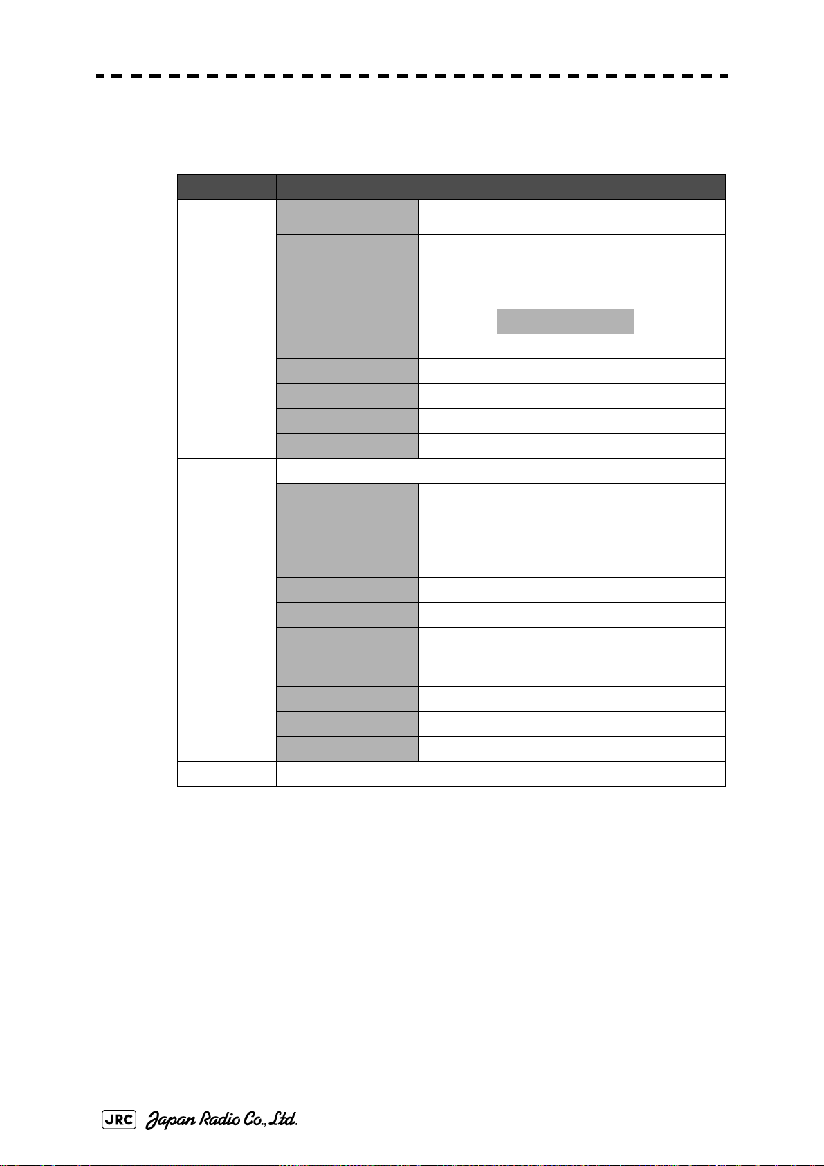
JMA-9132-SA
Tab le 1- 1: JMA-9100 SERIES RADAR LIST OF COMPOSITION (Self-Standing TYPE)
Tab le 1- 2: JMA-9100 SERIES RADAR LIST OF COMPOSITION (Desktop TYPE)
Scanner Unit: NKE-1130
Table1-6: JMA-9132-SA SCANNER UNIT
2.1.2 2695110056
2.2.5 NKE-1130 type scanner
2.4 PRECAUTIONS
Display Unit (self standing): NCD-4990
Table1-11: NCD-4990/NCD-4990T DISPLAY UNIT
3.1 INSTALLATION OF DISPLAY UNIT
3.3.1 Connections with NKE-1125,NTG-3225,NKE-1130,NTG-3230
OPTION Interswitch Unit: NQE-3141-2/4A/8A
5.1 INSTALLATION OF INTERSWITCH UNIT
Power Control Unit: NQE-3167
5.2.2 Connections to NKE-1125, NTG-3225, NKE-1130, and NTG-
3230
5.2.5 Connection to display unit
VDR I/F Kit: CQD-1891
5.3 INSTALLATION OF VDR
Page 11

Cross Reference
JMA-9123-7XA/9XA
Tab le 1- 1: JMA-9100 SERIES RADAR LIST OF COMPOSITION (Self-Standing TYPE)
Tab le 1- 2: JMA-9100 SERIES RADAR LIST OF COMPOSITION (Desktop TYPE)
Scanner Unit: NKE-1129
Table1-7: JMA-9123-7XA/JMA-9123-9XA SCANNER and TRANSMITTER-RECEIVER
UNIT
2.1.2 2695110056
2.2.4 NKE-1129 type scanner
2.4 PRECAUTIONS
Transmiter Receiver Unit: NTG-3225
2.3.1 NTG-3225 type transmitter receiver
Display Unit (self standing): NCD-4990
Table1-11: NCD-4990/NCD-4990T DISPLAY UNIT
3.1 INSTALLATION OF DISPLAY UNIT
3.3.1 Connections with NKE-1125,NTG-3225,NKE-1130,NTG-3230
OPTION Interswitch Unit: NQE-3141-2/4A/8A
5.1 INSTALLATION OF INTERSWITCH UNIT
Power Control Unit: NQE-3167
5.2.2 Connections to NKE-1125, NTG-3225, NKE-1130, and NTG-
3230
5.2.5 Connection to display unit
VDR I/F Kit: CQD-1891
5.3 INSTALLATION OF VDR
iii
Page 12

JMA-9122-6XA/9XA
Tab le 1- 1: JMA-9100 SERIES RADAR LIST OF COMPOSITION (Self-Standing TYPE)
Tab le 1- 2: JMA-9100 SERIES RADAR LIST OF COMPOSITION (Desktop TYPE)
Scanner Unit: NKE-1125
Table1-8: JMA-9122-6XA/JMA-9122-9XA SCANNER UNIT
2.1.2 2695110056
2.2.3 NKE-1125 type scanner
2.4 PRECAUTIONS
Display Unit (self standing): NCD-4990
Table1-11: NCD-4990/NCD-4990T DISPLAY UNIT
3.1 INSTALLATION OF DISPLAY UNIT
3.3.1 Connections with NKE-1125,NTG-3225,NKE-1130,NTG-3230
OPTION Interswitch Unit: NQE-3141-2/4A/8A
5.1 INSTALLATION OF INTERSWITCH UNIT
Power Control Unit: NQE-3167
5.2.2 Connections to NKE-1125, NTG-3225, NKE-1130, and NTG-
3230
5.2.5 Connection to display unit
VDR I/F Kit: CQD-1891
5.3 INSTALLATION OF VDR
iv
Page 13

Cross Reference
JMA-9122-6XAH
Tab le 1- 1: JMA-9100 SERIES RADAR LIST OF COMPOSITION (Self-Standing TYPE)
Tab le 1- 2: JMA-9100 SERIES RADAR LIST OF COMPOSITION (Desktop TYPE)
Scanner Unit: NKE-2254-6HS
Table1-9: JMA-9122-6XAH SCANNER UNIT
2.1.1 CFQ-6912-**
2.2.2 NKE-2254 type scanner
2.4 PRECAUTIONS
Display Unit (self standing): NCD-4990
Table1-11: NCD-4990/NCD-4990T DISPLAY UNIT
3.1 INSTALLATION OF DISPLAY UNIT
3.2 INSTALLATION OF AC-DC CONVERTER NBA-5135
3.3.2 Connections with NKE-2103,NKE-2254
OPTION Interswitch Unit: NQE-3141-2/4A/8A
5.1 INSTALLATION OF INTERSWITCH UNIT
Power Control Unit: NQE-3167
5.2.1 Connection with NKE-2103 type and NKE-2254-6HS type
scanners
5.2.5 Connection to display unit
VDR I/F Kit: CQD-1891
5.3 INSTALLATION OF VDR
v
Page 14

JMA-9110-6XA/6XAH
Tab le 1- 1: JMA-9100 SERIES RADAR LIST OF COMPOSITION (Self-Standing TYPE)
Tab le 1- 2: JMA-9100 SERIES RADAR LIST OF COMPOSITION (Desktop TYPE)
Scanner Unit: NKE-2103
Table1-10: JMA-9110-6XA/JMA-9110-6XAH SCANNER UNIT
2.1.1 CFQ-6912-**
2.2.1 NKE-2103 type scanner
2.4 PRECAUTIONS
Display Unit (self standing): NCD-4990
Table1-11: NCD-4990/NCD-4990T DISPLAY UNIT
3.1 INSTALLATION OF DISPLAY UNIT
3.2 INSTALLATION OF AC-DC CONVERTER NBA-5135
5.2.1 Connection with NKE-2103 type and NKE-2254-6HS type scanners
OPTION Interswitch Unit: NQE-3141-2/4A/8A
5.1 INSTALLATION OF INTERSWITCH UNIT
Power Control Unit: NQE-3167
5.2.1 Connection with NKE-2103 type and NKE-2254-6HS type
scanners
5.2.5 Connection to display unit
VDR I/F Kit: CQD-1891
5.3 INSTALLATION OF VDR
vi
Page 15

Cross Reference
JMA-7133-SA
Tab le 1- 3: JMA-7100 SERIES RADAR LIST OF COMPOSITION (Self-Standing TYPE)
Tab le 1- 4: JMA-7100 SERIES RADAR LIST OF COMPOSITION (Desktop TYPE)
Scanner Unit: NKE-1139
Table1-12: JMA-7133-SASCANNER and TRANSMITTER RECEIVER UNIT
2.1.2 2695110056
2.2.6 NKE-1139 type scanner
2.4 PRECAUTIONS
Transmiter Receiver Unit: NTG-3230
2.3.2 NTG-3230 type transmitter receiver
Display Unit (self standing): NCD-4790
Table1-18: NCD-4790/NCD-4790T DISPLAY UNIT
3.1 INSTALLATION OF DISPLAY UNIT
3.3.1 Connections with NKE-1125,NTG-3225,NKE-1130,NTG-3230
OPTION Interswitch Unit: NQE-3141-2/4A/8A
5.1 INSTALLATION OF INTERSWITCH UNIT
Power Control Unit: NQE-3167
5.2.2 Connections to NKE-1125, NTG-3225, NKE-1130, and NTG-
3230
5.2.5 Connection to display unit
VDR I/F Kit: CQD-1891
5.3 INSTALLATION OF VDR
vii
Page 16

JMA-7132-SA
Tab le 1- 3: JMA-7100 SERIES RADAR LIST OF COMPOSITION (Self-Standing TYPE)
Tab le 1- 4: JMA-7100 SERIES RADAR LIST OF COMPOSITION (Desktop TYPE)
Scanner Unit: NKE-1139
Table1-13: JMA-7132-SA SCANNER UNIT
2.1.2 2695110056
2.2.5 NKE-1130 type scanner
2.4 PRECAUTIONS
Display Unit (self standing): NCD-4790
Table1-18: NCD-4790/NCD-4790T DISPLAY UNIT
3.1 INSTALLATION OF DISPLAY UNIT
3.3.1 Connections with NKE-1125,NTG-3225,NKE-1130,NTG-3230
OPTION Interswitch Unit: NQE-3141-2/4A/8A
5.1 INSTALLATION OF INTERSWITCH UNIT
Power Control Unit: NQE-3167
5.2.2 Connections to NKE-1125, NTG-3225, NKE-1130, and NTG-
3230
5.2.5 Connection to display unit
VDR I/F Kit: CQD-1891
5.3 INSTALLATION OF VDR
viii
Page 17

Cross Reference
JMA-7123-7XA9XA
Tab le 1- 3: JMA-7100 SERIES RADAR LIST OF COMPOSITION (Self-Standing TYPE)
Tab le 1- 4: JMA-7100 SERIES RADAR LIST OF COMPOSITION (Desktop TYPE)
Scanner Unit: NKE-1139
Table1-14: JMA-7123-7XA/JMA-7123-9XASCANNER and TRANSMITTER RECEIVER
UNIT
2.1.2 2695110056
2.2.4 NKE-1129 type scanner
2.4 PRECAUTIONS
Transmiter Receiver Unit: NTG-3225
2.3.1 NTG-3225 type transmitter receiver
Display Unit (self standing): NCD-4790
Table1-18: NCD-4790/NCD-4790T DISPLAY UNIT
3.1 INSTALLATION OF DISPLAY UNIT
3.3.1 Connections with NKE-1125,NTG-3225,NKE-1130,NTG-3230
OPTION Interswitch Unit: NQE-3141-2/4A/8A
5.1 INSTALLATION OF INTERSWITCH UNIT
Power Control Unit: NQE-3167
5.2.2 Connections to NKE-1125, NTG-3225, NKE-1130, and NTG-
3230
5.2.5 Connection to display unit
VDR I/F Kit: CQD-1891
5.3 INSTALLATION OF VDR
ix
Page 18

JMA-7122-6XA/9XA
Tab le 1- 3: JMA-7100 SERIES RADAR LIST OF COMPOSITION (Self-Standing TYPE)
Tab le 1- 4: JMA-7100 SERIES RADAR LIST OF COMPOSITION (Desktop TYPE)
Scanner Unit: NKE-1125
Table1-15: JMA-7122-6XA/JMA-7122-9XA SCANNER UNIT
2.1.2 2695110056
2.2.3 NKE-1125 type scanner
2.4 PRECAUTIONS
Display Unit (self standing): NCD-4790
Table1-18: NCD-4790/NCD-4790T DISPLAY UNIT
3.1 INSTALLATION OF DISPLAY UNIT
3.3.1 Connections with NKE-1125,NTG-3225,NKE-1130,NTG-3230
OPTION Interswitch Unit: NQE-3141-2/4A/8A
5.1 INSTALLATION OF INTERSWITCH UNIT
Power Control Unit: NQE-3167
5.2.2 Connections to NKE-1125, NTG-3225, NKE-1130, and NTG-
3230
5.2.5 Connection to display unit
VDR I/F Kit: CQD-1891
5.3 INSTALLATION OF VDR
x
Page 19

Cross Reference
JMA-7122-6XAH
Tab le 1- 3: JMA-7100 SERIES RADAR LIST OF COMPOSITION (Self-Standing TYPE)
Tab le 1- 4: JMA-7100 SERIES RADAR LIST OF COMPOSITION (Desktop TYPE)
Scanner Unit: NKE-2254-6HS
Table1-16: JMA-7122-6XAH SCANNER UNIT
2.1.1 CFQ-6912-**
2.2.2 NKE-2254 type scanner
2.4 PRECAUTIONS
Display Unit (self standing): NCD-4790
Table1-18: NCD-4790/NCD-4790T DISPLAY UNIT
3.1 INSTALLATION OF DISPLAY UNIT
3.2 INSTALLATION OF AC-DC CONVERTER NBA-5135
3.3.2 Connections with NKE-2103,NKE-2254
OPTION Interswitch Unit: NQE-3141-2/4A/8A
5.1 INSTALLATION OF INTERSWITCH UNIT
Power Control Unit: NQE-3167
5.2.1 Connection with NKE-2103 type and NKE-2254-6HS type
scanners
5.2.5 Connection to display unit
VDR I/F Kit: CQD-1891
5.3 INSTALLATION OF VDR
xi
Page 20

JMA-7110-6XA/6XAH
Tab le 1- 3: JMA-7100 SERIES RADAR LIST OF COMPOSITION (Self-Standing TYPE)
Tab le 1- 4: JMA-7100 SERIES RADAR LIST OF COMPOSITION (Desktop TYPE)
Scanner Unit: NKE-2103
Table1-17: JMA-7110-6XA/JMA-7110-6XAH SCANNER UNIT
2.1.1 CFQ-6912-**
2.2.1 NKE-2103 type scanner
2.4 PRECAUTIONS
Display Unit (self standing): NCD-4790
Table1-18: NCD-4790/NCD-4790T DISPLAY UNIT
3.1 INSTALLATION OF DISPLAY UNIT
3.2 INSTALLATION OF AC-DC CONVERTER NBA-5135
3.3.2 Connections with NKE-2103,NKE-2254
OPTION Interswitch Unit: NQE-3141-2/4A/8A
5.1 INSTALLATION OF INTERSWITCH UNIT
Power Control Unit: NQE-3167
5.2.1 Connection with NKE-2103 type and NKE-2254-6HS type
scanners
5.2.5 Connection to display unit
VDR I/F Kit: CQD-1891
5.3 INSTALLATION OF VDR
xii
Page 21
Modified November 20, 2008 11:28
1 EQUIPMENT COMPOSITION
2 INSTALLATION OF SCANNER UNIT
3 INSTALLATION OF DISPAY UNIT
4 INITIAL SETTING
5 OPTION UNIT
1
2
3
4
6 APPENDIX
5
6
Page 22

Page 23
SECTION 1
EQUIPMENT COMPOSITION
EQUIPMENT COMPOSITION
1.1 GENERAL COMPOSITION ....................................................................1-1
1.1.1 JMA-9100 SERIES RADAR ....................................................................... 1-1
1.1.2 JMA-7100 SERIES RADAR ....................................................................... 1-2
1.2 LIST OF CIRCUITS ................................................................................1-4
1.2.1 JMA-9100 SERIES RADAR ....................................................................... 1-4
1.2.2 JMA-7100 SERIES RADAR ..................................................................... 1-11
Page 24

Page 25
JMA-9100/7100 Installation Manual > 1.EQUIPMENT COMPOSITION > 1.1 GENERAL COMPOSITION
1.1 GENERAL COMPOSITION
1.1.1 JMA-9100 SERIES RADAR
Table1-1: JMA-9100 SERIES RADAR LIST OF COMPOSITION (Self-Standing TYPE)
1
MODEL SCANNER UNIT RADIATOR
JMA-9133-SA NKE-1139 NJU-84 NTG-3230 NCD-4990
JMA-9132-SA NKE-1130
JMA-9123-7XA NKE-1129-7 NAX-16B-7 NJU-85 NTG-3225
JMA-9123-9XA NKE-1129-9 NAX-16B-9
JMA-9122-6XA NKE-1125-6 NAX-16B-6
JMA-9122-9XA NKE-1125-9 NAX-16B-9
JMA-9122-6XAH NKE-2254-6HS NAX-16B-6
JMA-9110-6XA NKE-2103-6 NAX-16B-6
JMA-9110-6XAH NKE-2103-6HS NAX-16B-6
PERFORMANCE
MONITOR
TRANSMITTERR
ECEIVER UNIT
―
―
―
― NBA-5135
―
―
DISPLAY
UNIT
Tabl e 1-2: JMA-9100 SERIES RADAR LIST OF COMPOSITION (Desktop TYPE)
MODEL SCANNER UNIT RADIATOR
JMA-9133-SA NKE-1139 NJU-84 NTG-3230 Display unit:
JMA-9132-SA NKE-1130
JMA-9123-7XA NKE-1129-7 NAX-16B-7 NJU-85 NTG-3225
JMA-9123-9XA NKE-1129-9 NAX-16B-9
JMA-9122-6XA NKE-1125-6 NAX-16B-6
JMA-9122-9XA NKE-1125-9 NAX-16B-9
JMA-9122-6XAH NKE-2254-6HS NAX-16B-6
JMA-9110-6XA NKE-2103-6 NAX-16B-6
JMA-9110-6XAH NKE-2103-6HS NAX-16B-6
PERFORMANC
EMONITOR
TRANSMITTER
RECEIVER UNIT
――
――
――
―
―
―
DISPLAY UNIT AC-DC
NWZ-170
Radar Process
Unit:
NDC-1399-9
Operation Unit:
NCE-5163
AC-DC
CONVERTER
―
(Built in a
display unit)
CONVERTER
―
―
―
NBA-5135
*1Input voltage is selectable. '1' or '2' suffix is attached to model name of scanner
unit. '1' means AC100-115V(50/60Hz) and '2' means AC220-240V(50/60Hz) for
type of scanner unit NKE-1139, NKE-1130, NKE-1129-7,NKE-1129-9, NKE1125-6 and NKE-1125-9. Others are DC input.
*2HEATER OPTION is available at suffix 'D' exclude type NKE-2103.
1- 1
Page 26
JMA-9100/7100 Installation Manual > 1.EQUIPMENT COMPOSITION > 1.1 GENERAL COMPOSITION
Ex)NKE-1139-1 D, NKE-1129-92 D, NKE-2254-6HSD,
AC 100-115V 50/60Hz 1φ
1:
AC 220-240V 50/60Hz 1φ
2:
HEATER OPTION
D:
1.1.2 JMA-7100 SERIES RADAR
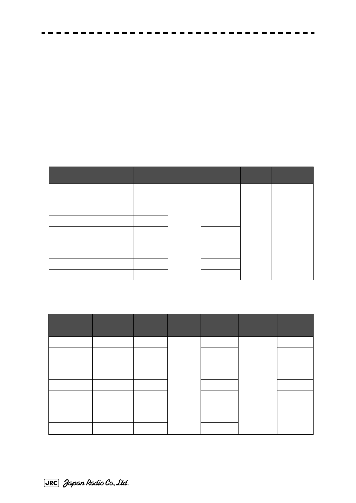
Table1 -3: JMA-7100 SERIES RADAR LIST OF COMPOSITION (Self-Standing TYPE)
MODEL SCANNER UNIT RADIATOR
JMA-7133-SA NKE-1139 NJU-84 NTG-3230 NCD-4790
JMA-7132-SA NKE-1130
JMA-7123-7XA NKE-1129-7 NAX-16B-7 NJU-85 NTG-3225
JMA-7123-9XA NKE-1129-9 NAX-16B-9
JMA-7122-6XA NKE-1125-6 NAX-16B-6
JMA-7122-9XA NKE-1125-9 NAX-16B-9
JMA-7122-6XAH NKE-2254-6HS NAX-16B-6
JMA-7110-6XA NKE-2103-6 NAX-16B-6
JMA-7110-6XAH NKE-2103-6HS NAX-16B-6
PERFORMAN
CEMONITOR
TRANSMITTER
RECEIVER UNIT
―
―
―
― NBA-5135
―
―
DISPLAY
UNIT
Table1- 4: JMA-7100 SERIES RADAR LIST OF COMPOSITION (Desktop TYPE)
MODEL SCANNER UNIT RADIATOR
JMA-7133-SA NKE-1139 NJU-84 NTG-3230 Display unit:
JMA-7132-SA NKE-1130
JMA-7123-7XA NKE-1129-7 NAX-16B-7 NJU-85 NTG-3225
JMA-7123-9XA NKE-1129-9 NAX-16B-9
JMA-7122-6XA NKE-1125-6 NAX-16B-6
JMA-7122-9XA NKE-1125-9 NAX-16B-9
JMA-7122-6XAH NKE-2254-6HS NAX-16B-6
JMA-7110-6XA NKE-2103-6 NAX-16B-6
JMA-7110-6XAH NKE-2103-6HS NAX-16B-6
PERFORMAN
CEMONITOR
TRANSMITTER
RECEIVER UNIT
――
――
――
―
―
―
DISPLAY UNIT AC-DC
NWZ-170
Radar Process
Unit:
NDC-1399-9
Operation
Unit:
NCE-5163
AC-DC
CONVERTER
―
(DISPLAY UNIT
に内蔵)
CONVERTER
―
―
―
NBA-5135
1- 2
Page 27

JMA-9100/7100 Installation Manual > 1.EQUIPMENT COMPOSITION > 1.1 GENERAL COMPOSITION
*1Input voltage is selectable. '1' or '2' suffix is attached to model name of scanner
unit. '1' means AC100-115V(50/60Hz) and '2' means AC220-240V(50/60Hz) for
type of scanner unit NKE-1139,NKE-1130,NKE-1129-7,NKE-1129-9,NKE-11256 and NKE-1125-9. Others are DC input.
*2HEATER OPTION is available at suffix 'D' exclude type NKE-2103.
Ex)NKE-1139-1 D, NKE-1129-92 D, NKE-2254-6HSD,、
AC 100-115V 50/60Hz 1φ
1:
AC 220-240V 50/60Hz 1φ
2:
HEATER OPTION
D:
1
1- 3
Page 28

JMA-9100/7100 Installation Manual > 1.EQUIPMENT COMPOSITION > 1.2 LIST OF CIRCUITS
1.2 LIST OF CIRCUITS
1.2.1 JMA-9100 SERIES RADAR
Table1 -5: JMA-9133-SA SCANNER and TRANSMITTER RECEIVER UNIT
NKE-1139-1 NKE-1139-2
SCANNER
UNIT
SCANNER UNIT
INTERCONNECTION
RADIATOR CTG-270
SAFETY SWITCH CSD-657
ENCODER CHT-71A1
CAX-14
TRANSMITTE
R
RECEIVER
UNIT
MOTOR MDBW10823
AC100V MOTOR DRIVER
BREAK CIRCUIT CFA-255
BREAK CONTROL CIRCUIT
BREAK UNIT NZR-17
HEATER CONTROL PART
PERFORMANCE MONITOR
NTG-3230
TRANSCEIVER UNIT
INTERCONNECTION
MODULATOR UNIT NMA-553-1
MODULATOR UNIT
INTERCONNECTION
MODULATOR CIRCUIT CPA-264
RECEIVER CIRCUIT NRG-229
RECEIVER UNIT
INTERCONNECTION
IF CIRCUIT CAE-499
7EPRD0035
AC220V MOTOR DRIVER
CCB-655
CHG-215
NJU-84
CMK-594
CMB-407
CMA-902
7EPRD0034
DISPLAY
UNIT
RF CIRCUIT CAF-595
T/R CONTROL CIRCUIT CMC-1205R
RELAY FILTER CIRCUIT CSC-656
POEWR SUPPLY CIRCUIT
NCD-4990/T
CBD-1682A
1- 4
Page 29
SCANNER
UNIT
JMA-9100/7100 Installation Manual > 1.EQUIPMENT COMPOSITION > 1.2 LIST OF CIRCUITS
Tab l e 1-6: JMA-9132-SA SCANNER UNIT
NKE-1130-1 NKE-1130-2
SCANNER UNIT
INTERCONNECTION
RADIATOR CTG-270
SAFETY SWITCH CSD-656
ENCODER CHT-71A
MOTOR MDBW10823
CAX-13
1
AC100V MOTOR DRIVER
BREAK CIRCUIT CFA-255
BREAK CONTROL CIRCUIT
BREAK UNIT NZR-17
MODULATOR UNIT NMA-551-1
MODULATOR UNIT
INTERCONNECTION
MODULATOR CIRCUIT CPA-264
RECEIVER CONTROL
UNTI
RECEIVER UNIT NRG-229
RECEIVER UNIT
INTERCONNECTION
IF CIRCUIT CAE-499
RF CIRCUIT CAF-595
T/R CONTROL CIRCUIT CMC-1205R
RELAY FILTER CIRCUIT CSC-656
POWER SUPPLY CIRCUIT
7EPRD0035
AC220V MOTOR DRIVER
CCB-655
CMB-406
NZT-1130
CMA-902
CBD-1682A
7EPRD0034
DISPLAY
UNIT
HEATER CONTROL PART
PERFORMANCE MONITOR
NCD-4990/T
1- 5
CHG-215
NJU-84
Page 30
JMA-9100/7100 Installation Manual > 1.EQUIPMENT COMPOSITION > 1.2 LIST OF CIRCUITS
Tab l e 1-7: JMA-9123-7XA/JMA-9123-9XA SCANNER and TRANSMITTER-RECEIVER UNIT
NKE-1129-1 NKE-1129-2
SCANNER
UNIT
SCANNER UNIT
INTERCONNECTION
SAFETY SWITCH CSD-655
ENCODER CHT-71A1
MOTOR MDBW10822
CAX-12
TRANSMITTER
RECEIVER
UNIT
AC100V MOTOR DRIVER
7EPRD0035
AC220V MOTOR DRIVER
BREAK CIRCUIT CFA-253
BREAK CONTROL CIRCUIT
CCB-655
BREAK UNIT NZR-15
HEATER CONTROL PART
PERFORMANCE MONITOR
CHG-216
NJU-85
NTG-3225
TRANSCEIVER UNIT
INTERCONNECTION
CMK-593
MODULATOR UNIT NMA-552-1
MODULATOR UNIT
INTERCONNECTION
CMB-405
MODULATOR CIRCUIT CPA-264
RECEIVER CIRCUIT CFR-229
RECEIVER UNIT
INTERCONNECTION
NRG-162A
IF CIRCUIT CMA-866A
RF CIRCUIT CMC-1205R
7EPRD0034
T/R CONTROL CIRCUIT CSC-656
RELAY FILTER CIRCUIT CBD-1682A
DISPLAY UNIT NCD-4990/T
1- 6
Page 31

SCANNER
UNIT
JMA-9100/7100 Installation Manual > 1.EQUIPMENT COMPOSITION > 1.2 LIST OF CIRCUITS
Table1- 8: JMA-9122-6XA/JMA-9122-9XA SCANNER UNIT
NKE-1125-61,NKE-1125-91 NKE-1125-62,NKE-1125-92
SCANNER UNIT
INTERCONNECTION
SAFETY SWITCH CSD-654
ENCODER CHT-71A
MOTOR MDBW10822
CAX-11
1
DISPLAY
UNIT
AC100V MOTOR DRIVER
BREAK CIRCUIT CFA-253
BREAK CONTROL CIRCUIT
BREAK UNIT NZR-16
MODULATOR UNIT NMA-550-1
MODULATOR UNIT
INTERCONNECTION
MODULATOR CPA-264
MAG FILTER CIRCUIT CFR-229
RECEIVER UNIT NRG-162A
RECEIVER CIRCUIT CMA-866A
T/R CONTROL CIRCUIT CMC-1205R
RELAY FILTER CIRCUIT CSC-656
POWER SUPPLY CIRCUIT
HEATER CONTROL PART
PERFORMANCE MONITOR
NCD4990/T
7EPRD0035
AC220V MOTOR DRIVER
CCB-655
CMB-404
CBD-1682A
CHG-216
NJU-85
7EPRD0034
1- 7
Page 32

JMA-9100/7100 Installation Manual > 1.EQUIPMENT COMPOSITION > 1.2 LIST OF CIRCUITS
Table1 -9: JMA-9122-6XAH SCANNER UNIT
NKE-2254-6HS
SCANNER UNIT
SCANNER UNIT
INTERCONNECTION
SAFETY SWITCH CSD-653
ENCODER CHT-71A
MOTOR 7BDRD0045A
CAX-15
MOTOR CONTROL
POWER SUPPLY
BREAK CIRCUIT CFA-257
MODULATOR UNIT NMA-550-1
MODULATOR UNIT
INTERCONNECTION
MODULATOR
CIRCUIT
MAG FILTER CIRCUIT CFR-229
RECEIVER UNIT NRG-162A
RECEIVER CIRCUIT CMA-866A
T/RCONTROL CIRCUIT
POWER SUPPLY
CIRCUIT
HEATER CONTROL PART
PERFORMANCE
MONITOR
DISPLAY UNIT NCD-4990/T
AC-DC
NBA-5135
CONVERTER
CBD-1779
CMB-404
CPA-264
CMC-1205R
CBD-1682A
CHG-216
NJU-85
1- 8
Page 33

JMA-9100/7100 Installation Manual > 1.EQUIPMENT COMPOSITION > 1.2 LIST OF CIRCUITS
Table1 -10: JMA-9110-6XA/JMA-9110-6XAH SCANNER UNIT
NKE-2103-6,NKE-2103-6HS
SCANNER UNIT
SCANNER UNIT
INTERCONNECTION
ENCODER CHT-71A
MOTOR 7BDRD0048
BREAK CIRCUIT CFA-252
CAX-10
1
TRANSMITTER
RECEIVER UNIT
TRANSMITTER
RECEIVER UNIT
INTERCONNECTION
MODULATORCIRCUIT CME-363
POWER SUPPLY CIRCUIT
MOTOR CONTROL POWER
SUPPLY
RECEIVER UNIT NRG-610
RECEIVER UNIT
INTERCONNECTION
IF AMP CIRCUIT CAE-529-1
PERFORMANCE MONITOR
DISPLAY UNIT NCD-4990/T
AC-DC
CONVERTER
NBA-5135
NZT-2103
CMK-599
CBD-1783
CBD-1779
CMA-823
NJU-85
1- 9
Page 34

JMA-9100/7100 Installation Manual > 1.EQUIPMENT COMPOSITION > 1.2 LIST OF CIRCUITS
Table1-11: NCD-4990/NCD-4990T DISPLAY UNIT
NCD-4990 NCD-4990T
RADAR
NDC-1399-9 NDC-1399-9
PROCESS
UNIT
OPERATION
UNIT
RADAR PROCESS
CDC-1324
CIRCUIT
AIS PROCESS
CDC-1325
CIRCUIT
ARPA PROCESS
CDC-1186D
CIRCUIT
GYRO I/FCIRCUIT CMJ-462E
MOTHER BOARD CQC-1192
TERMINAL BOARD
CQD-2097
CIRCUIT
POWER SUPPLY CBD-1661
RADAR PROCESS
UNIT
INTERCONNECTION
CML-763
RADAR PROCESS
UNIT
INTERCONNECTION
NCE-5163 NCE-5163
OPERATION
CCK-973
CIRCUITA
OPERATION
CCK-974
CIRCUITB
OPERATION
CCK-976
CIRCUITD
OPERATION UNIT
INTERCONNECTION
CMD-996-R
OPERATION UNIT
INTERCONNECTION
CML-763T
CMD-996-RT
MONITOR UNIT
AC-DC
CONVERTER
RADAR PROCESS
NWZ-170
CIRCUIT
AIS PROCESS
CML-799
CIRCUIT
ARPA PROCESS
CCK-972
CIRCUIT
GYRO I/FCIRCUIT CML-764-R
MONITOR UNIT
INTERCONNECTION
NBA-5135 *(Only for NKE-2103-6/6HS,NKE-2254-6/6HS)
CML-764-RT
1- 10
Page 35

JMA-9100/7100 Installation Manual > 1.EQUIPMENT COMPOSITION > 1.2 LIST OF CIRCUITS
1.2.2 JMA-7100 SERIES RADAR
Table1-12: JMA-7133-SASCANNER and TRANSMITTER RECEIVER UNIT
NKE-1139-1 NKE-1139-2
SCANNER
UNIT
TRANSMITTER
RECEIVER
UNIT
SCANNER UNIT
INTERCONNECTION
RADIATOR CTG-270
SAFETY SWITCH CSD-657
ENCODER CHT-71A1
MOTOR MDBW10823
AC100V MOTOR DRIVER
BREAK CIRCUIT CFA-255
BREAK CONTROL CIRCUIT
BREAK UNIT NZR-17
HEATER CONTROL PART
PERFORMANCE MONITOR
NTG-3230
TRANSCEIVER UNIT
INTERCONNECTION
7EPRD0035
AC220V MOTOR DRIVER
CAX-14
CCB-655
CHG-215
NJU-84
CMK-594
1
7EPRD0034
MODULATOR UNIT NMA-553-1
MODULATOR UNIT
INTERCONNECTION
MODULATOR CIRCUIT CPA-264
RECEIVER CIRCUIT NRG-229
RECEIVER UNIT
INTERCONNECTION
IF CIRCUIT CAE-499
RF CIRCUIT CAF-595
T/R CONTROL CIRCUIT CMC-1205R
RELAY FILTER CIRCUIT CSC-656
POEWR SUPPLY CIRCUIT
DISPLAY UNIT NCD-4790/T
CMB-407
CMA-902
CBD-1682A
1- 11
Page 36

JMA-9100/7100 Installation Manual > 1.EQUIPMENT COMPOSITION > 1.2 LIST OF CIRCUITS
Table1 -13: JMA-7132-SA SCANNER UNIT
NKE-1130-1 NKE-1130-2
SCANNER
UNIT
SCANNER UNIT
INTERCONNECTION
RADIATOR CTG-270
SAFETY SWITCH CSD-656
ENCODER CHT-71A
MOTOR MDBW10823
CAX-13
AC100V MOTOR DRIVER
7EPRD0035
AC220V MOTOR DRIVER
BREAK CIRCUIT CFA-255
BREAK CONTROL CIRCUIT
CCB-655
BREAK UNIT NZR-17
MODULATOR UNIT NMA-551-1
MODULATOR UNIT
CMB-406
INTERCONNECTION
MODULATOR CIRCUIT CPA-264
RECEIVER CONTROL
NZT-1130
UNTI
RECEIVER UNIT NRG-229
RECEIVER UNIT
CMA-902
INTERCONNECTION
IF CIRCUIT CAE-499
RF CIRCUIT CAF-595
T/R CONTROL CIRCUIT CMC-1205R
RELAY FILTER CIRCUIT CSC-656
POWER SUPPLY CIRCUIT
CBD-1682A
7EPRD0034
DISPLAY
UNIT
HEATER CONTROL PART
PERFORMANCE MONITOR
NCD-4790/T
CHG-215
NJU-84
1- 12
Page 37

JMA-9100/7100 Installation Manual > 1.EQUIPMENT COMPOSITION > 1.2 LIST OF CIRCUITS
Tab l e 1-14: JMA-7123-7XA/JMA-7123-9XASCANNER and TRANSMITTER RECEIVER UNIT
NKE-1129-71,NKE-1129-91 NKE-1129-72,NKE-1129-92
SCANNER
UNIT
SCANNER UNIT
INTERCONNECTION
SAFETY SWITCH CSD-655
ENCODER CHT-71A1
MOTOR MDBW10822
CAX-12
1
TRANSMITTER
RECEIVER
UNIT
AC100V MOTOR DRIVER
BREAK CIRCUIT CFA-253
BREAK CONTROL CIRCUIT
BREAK UNIT NZR-15
HEATER CONTROL PART
PERFORMANCE MONITOR
NTG-3225
TRANSCEIVER UNIT
INTERCONNECTION
MODULATOR UNIT NMA-552-1
MODULATOR UNIT
INTERCONNECTION
MODULATOR CIRCUIT CPA-264
RECEIVER CIRCUIT CFR-229
RECEIVER UNIT
INTERCONNECTION
IF CIRCUIT CMA-866A
RF CIRCUIT CMC-1205R
7EPRD0035
AC220V MOTOR DRIVER
CCB-655
CHG-216
NJU-85
CMK-593
CMB-405
NRG-162A
7EPRD0034
T/R CONTROL CIRCUIT CSC-656
RELAY FILTER CIRCUIT CBD-1682A
DISPLAY UNIT NCD-4790/T
1- 13
Page 38

JMA-9100/7100 Installation Manual > 1.EQUIPMENT COMPOSITION > 1.2 LIST OF CIRCUITS
Table1- 15: JMA-7122-6XA/JMA-7122-9XA SCANNER UNIT
NKE-1125-61,NKE-1125-91 NKE-1125-62,NKE-1125-92
SCANNER
UNIT
SCANNER UNIT
INTERCONNECTION
SAFETY SWITCH CSD-654
ENCODER CHT-71A
MOTOR MDBW10822
CAX-11
DISPLAY
UNIT
AC100V MOTOR DRIVER
7EPRD0035
AC220VMOTOR DRIVER
BREAKCIRCUIT CFA-253
BREAK CONTROL CIRCUIT
CCB-655
BREAK UNIT NZR-16
MODULATOR UNIT NMA-550-1
MODULATOR UNIT
CMB-404
INTERCONNECTION
MODULATORCIRCUIT CPA-264
MAG FILTER CIRCUIT CFR-229
RECEIVER UNIT NRG-162A
RECEIVERCIRCUIT CMA-866A
T/R CONTROL CIRCUIT CMC-1205R
RELAY FILTER CIRCUIT CSC-656
POWER SUPPLY CIRCUIT
HEATER CONTROL PART
PERFORMANCE MONITOR
CBD-1682A
CHG-216
NJU-85
NCD-4790/T
7EPRD0034
1- 14
Page 39

JMA-9100/7100 Installation Manual > 1.EQUIPMENT COMPOSITION > 1.2 LIST OF CIRCUITS
Tabl e 1-16: JMA-7122-6XAH SCANNER UNIT
NKE-2254-6HS
SCANNER UNIT
SCANNER UNIT
INTERCONNECTION
SAFETY SWITCH CSD-653
ENCODER CHT-71A
MOTOR 7BDRD0045A
CAX-15
1
MOTOR CONTROL
POWERSUPPLY
BREAK CIRCUIT CFA-257
MODULATOR UNIT NMA-550-1
MODULATOR UNIT
NTERCONNECTION
MODULATORCIRCUIT CPA-264
MAG FILTER CIRCUIT CFR-229
RECEIVER UNIT NRG-162A
RECEIVERCIRCUIT CMA-866A
T/R CONTROL CIRCUIT CMC-1205R
POWER SUPPLY CIRCUIT
HEATER CONTROL PART
PERFORMANCE MONITOR
DISPLAY UNIT NCD-4790/T
CBD-1779
CMB-404
CBD-1682A
CHG-216
NJU-85
1- 15
Page 40

JMA-9100/7100 Installation Manual > 1.EQUIPMENT COMPOSITION > 1.2 LIST OF CIRCUITS
Table1 -17: JMA-7110-6XA/JMA-7110-6XAH SCANNER UNIT
NKE-2103-6,NKE-2103-6HS
SCANNER UNIT
SCANNER UNIT
INTERCONNECTION
ENCODER CHT-71A
MOTOR 7BDRD0048
BREAK CIRCUIT CFA-252
CAX-10
TRANSMITTER
RECEIVER UNIT
TRANSMITTER
RECEIVER UNIT
INTERCONNECTION
MODULATORCIRCUIT CME-363
POWER SUPPLY
CIRCUIT
MOTOR CONTROL
POWER SUPPLY
RECEIVER UNIT NRG-610
RECEIVER UNIT
INTERCONNECTION
IF AMP CIRCUIT CAE-529-1
PERFORMANCE
MONITOR
DISPLAY UNIT NCD-4790/T
AC-DC
NBA-5135
CONVERTER
NZT-2103
CMK-599
CBD-1783
CBD-1779
CMA-823
NJU-85
1- 16
Page 41

JMA-9100/7100 Installation Manual > 1.EQUIPMENT COMPOSITION > 1.2 LIST OF CIRCUITS
Table1 -18: NCD-4790/NCD-4790T DISPLAY UNIT
NCD-4790 NCD-4790T
RADAR PROCESS
UNIT
NDC-1399-7 NDC-1399-7
RADAR PROCESS
CIRCUIT
CDC-1324
1
OPERATION
UNIT
AIS PROCESS
CIRCUIT
ARPA PROCESS
CIRCUIT
GYRO I/FCIRCUIT CMJ-462E
MOTHER BOARD CQC-1192
TERMINAL
BOARD CIRCUIT
POWER SUPPLY CBD-1661
RADAR PROCESS
UNIT
INTERCONNECTION
NCE-5163 NCE-5163
OPERATION
CIRCUITA
OPERATION
CIRCUITB
OPERATION
CIRCUITD
OPERATION UNIT
INTERCONNECTION
CDC-1325
CDC-1186D
CQD-2097
CML-763
CCK-973
CCK-974
CCK-976
CMD-996-R
RADAR PROCESS
UNIT
INTERCONNECTION
OPERATION UNIT
INTERCONNECTION
CML-763T
CMD-996-RT
MONITOR UNIT NWZ-173 NWZ-173
AC-DC
CONVERTER
NBA-5135 *(Only for NKE-2103-6/6HS,NKE-2254-6/6HS)
1- 17
Page 42

JMA-9100/7100 Installation Manual > 1.EQUIPMENT COMPOSITION > 1.2 LIST OF CIRCUITS
1- 18
Page 43

SECTION 2
INSTALLATION OF SCANNER UNIT
INSTALLATION OF SCANNER UNIT
2.1 EQUIPMENT CABLE .............................................................................2-1
2.1.1 CFQ-6912-** ...............................................................................................2-1
2.1.2 2695110056 ................................................................................................2-2
2.1.3 2695111153 ................................................................................................2-3
2.1.4 Cable end processing method .................................................................2-4
2.1.5 Connection to the display-unit side terminal block ............................... 2-7
2.2 INSTALLATION OF SCANNER UNIT ....................................................2-8
2.2.1 NKE-2103 type scanner ............................................................................ 2-8
2.2.2 NKE-2254 type scanner .......................................................................... 2-11
2.2.3 NKE-1125 type scanner .......................................................................... 2-13
2.2.4 NKE-1129 type scanner .......................................................................... 2-15
2.2.5 NKE-1130 type scanner .......................................................................... 2-17
2.2.6 NKE-1139 type scanner .......................................................................... 2-19
2.3 INSTALLATION OF TRANSMITTER RECEIVER UNIT ......................2-21
2.3.1 NTG-3225 type transmitter receiver ......................................................2-21
2.3.2 NTG-3230 type transmitter receiver ......................................................2-24
2.4 PRECAUTIONS ....................................................................................2-26
Page 44

2.4.1 Installation of scanner unit .................................................................... 2-26
2.4.2 Routing coaxial cable and flexible waveguide ..................................... 2-29
2.4.3 Scanner installation position .................................................................2-31
2.4.4 Confirmation during test run .................................................................2-35
2.4.5 Others .......................................................................................................2-35
Page 45

JMA-9100/7100 Installation Manual > 2.INSTALLATION OF SCANNER UNIT > 2.1 EQUIPMENT CABLE
2.1 EQUIPMENT CABLE
2.1.1 CFQ-6912-**
This is a 19-core shielded composite cable.
The cable length is indicated in the asterisks ** area in the model name, and the
available cable lengths are 5, 10, 20, 30, 40, 50, and 65 meters.
This cable is used to connect an NKE-2103 type scanner or an NKE-2254 type
scanner to the display unit.
2
Fig 2-1: Cross-sectional drawing of CFQ-6912
Table2-1: CFQ-6912 wire
Core(NO) AWG No. of Wire /φ Color Remarks
1 AWG24 7/0.2T Black1 Coaxial
2 AWG24 7/0.2T Black2 Shield
3 AWG24 7/0.2T Green
4 AWG24 7/0.2T Yellow
5 AWG24 7/0.2T White
6 AWG22 17/0.16T Black
7 AWG22 17/0.16T Orange
8 AWG16 50/0.18T Blue
9 AWG16 50/0.18T Gray
10 AWG16 50/0.18T Purple
11 AWG16 50/0.18T Brown
12 AWG16 50/0.18T White
13 AWG16 50/0.18T Orange
14 AWG16 50/0.18T Red
15 AWG16 50/0.18T Green
16 AWG16 50/0.18T Yellow
17 AWG16 50/0.18T Black
18 AWG16 50/0.18T Sky
19 AWG16 50/0.18T Pink
maximum diameter 14.5mm
2- 1
Page 46

JMA-9100/7100 Installation Manual > 2.INSTALLATION OF SCANNER UNIT > 2.1 EQUIPMENT CABLE
2.1.2 2695110056
This is a 14-core shielded composite cable.
This cable is used to connect an NKE-1125 type scanner or an NKE-1130 type
scanner, and an NTG-3225 type transmitter-receiver or a NTG-3230 type
transmitter-receiver to the display unit.
Fig 2-2: Cross-sectional drawing of 2695110056
Table2-2: 2695110056 wire
Core (No.) Cross
1 0.5 19 / 0.18 Black 1 Coaxial Cable
2 0.5 19 / 0.18 Black 2 Coaxial Cable
3 0.5 19 / 0.18 Black 3 Coaxial Cable
4 0.5 19 / 0.18 Black 4 Coaxial Cable
5 5.5 35 / 0.45 Yellow
6 5.5 35 / 0.45 Green
7 5.5 35 / 0.45 Brown
8 0.3 12 / 0.18 White Twisted pair cable with
9 0.3 12 / 0.18 Orange
10 2 37 / 0.26 Red
11 2 37 / 0.26 Blue
12 1.25 50 / 0.18 Black
13 1.25 50 / 0.18 Purple
14 0.5 1 / 0.18 Gray Shield wire
No. of wire / φ Color
Section
(m2)
Remarks
Shield sheath white
maximum diameter 23.0mm
2- 2
Page 47

JMA-9100/7100 Installation Manual > 2.INSTALLATION OF SCANNER UNIT > 2.1 EQUIPMENT CABLE
2.1.3 2695111153
This is an 18-core shielded composite cable.
This cable is used to connect an interswitch to the display unit.
2
Fig 2-3: Cross-sectional drawing of 2695111153
Table2-3: 2695111153 wire
Wire NO. Cross
A1 0.5 19 / 0.18 Black 1 Coaxial
A2 0.5 19 / 0.18 Black 2 Coaxial
B1 0.5 19 / 0.18 Blue Shield
B2 0.5 19 / 0.18 Yellow Shield
B3 0.5 19 / 0.18 Green Shield
B4 0.5 19 / 0.18 Red Shield
B5 0.5 19 / 0.18 Purple Shield
B6 0.5 19 / 0.18 Clear Shield
C1 0.3 12 / 0.18 Blue 2 Cores Shield
C2 0.3 12 / 0.18 Yellow 2 Cores Shield
D1 0.5 19 / 0.18 Brown
D2 0.5 19 / 0.18 Black
D3 0.5 19 / 0.18 Orange
D4 0.5 19 / 0.18 Gray
D5 0.5 19 / 0.18 Pink
D6 0.5 19 / 0.18 SkyBlue
No. of wire / φ Color
Section
(m2)
0.3 White
0.3 White
maximum diameter 18.0mm
Remarks
2- 3
Page 48

JMA-9100/7100 Installation Manual > 2.INSTALLATION OF SCANNER UNIT > 2.1 EQUIPMENT CABLE
2.1.4 Cable end processing method
Allow for sufficient cable length so that maintenance, inspection, and repair work
can be easily executed. Ensure a place to store the cable.
1) CFQ-6912
Cut off the metal shell connector.
Fig 2-4: CFQ-6912 Cutting position
Remove about one meter of the outer skin, and then process the double braided
shield according to the procedures shown below.
abt. 80 mm
taping
abt.
1000 mm
Terminal
CFQ-6912
Width for
clamping cable
abt.
30 mm
Fig 2-5: CFQ-6912 Processing of braided shield
Outer Shield
Outer Shield
2- 4
Page 49

JMA-9100/7100 Installation Manual > 2.INSTALLATION OF SCANNER UNIT > 2.1 EQUIPMENT CABLE
Process each cable end according to the procedures shown below.
Coaxial Cable
Shield Cable
Fig 2-6: CFQ-6912 End processing of each wire
Shield Cable
(twisted pair)
Vinyl Cable
Twist each pair of the following colored wires and clamp them to the crimp-type
terminal. (V2-M4 recommended)
• RED.T/GRN.T →+terminal
• WHT.T/ORN.T →+terminal
• PUR.T/BRN.T →-terminal
• BLU.T/GRY.T → -terminal
2
Overlay those wires as shown in the drawingat the
right, and fix them onto the CBD-1684A (TB522) or
TB401 terminal block.
Twist each pair of the following colored wires and
connect them to the TB4101 of the terminal board
circuit CQD-2097.
• YEL.T/PNK.T →TB4101(+48V)
• BLK.T/SKY.T → TB4101(+48VG)
Fig 2-7: Fixing onto the
terminal block
2- 5
Page 50

JMA-9100/7100 Installation Manual > 2.INSTALLATION OF SCANNER UNIT > 2.1 EQUIPMENT CABLE
2) 2695110056、2695111153
Remove about one meter of the outer skin, and then process the double braided
shield according to the procedures shown below.
Coaxial Cable
Shield Cable
abt. 80 mm
taping
abt.
1000 mm
2695110056
2695111153
Width for
clamping cable.
30 mm
abt.
Inner Shield
Outer Shield
Fig 2-8: 2695110056 Processing of braided shield
Shield Cable
(twisted pair)
Vinyl Cable
terminal
Fig 2-9: 2695110056 End processing of each wire
2- 6
Page 51

JMA-9100/7100 Installation Manual > 2.INSTALLATION OF SCANNER UNIT > 2.1 EQUIPMENT CABLE
2.1.5 Connection to the display-unit side terminal block
The terminal block of the display unit's terminal board circuit is a plug terminal
block which does not require a crimp-type terminal. Connection procedures are
described below.
1) Use a tool, such as a flathead screwdriver, to press the control so as to open
the cable inlet.
2) Check the length of the uninsulated portion of the electric wire and its
alignment, and then insert the electric wire until the end comes in contact
with the rear of the inlet.
3) Remove the tool from the control and securely tighten the cable. Properly
connect the cable in reference to the inter-board connection diagram.
2
4) After the cable has been connected, gently tug at the cable to ensure that it is
securely fastened.
Press down the lever to
open the cable inlet.
2.5mm
Insert the cable until it comes
contact with the rear of the inl
Gently tug at the cable to ensu
tha t it is securely fastened.
Appropriate
flathead
screwdriver
Fig 2-10: Terminal block connection method
2- 7
Page 52

JMA-9100/7100 Installation Manual > 2.INSTALLATION OF SCANNER UNIT > 2.2 INSTALLATION OF SCANNER UNIT
2.2 INSTALLATION OF SCANNER UNIT
2.2.1 NKE-2103 type scanner
2- 8
Page 53

JMA-9100/7100 Installation Manual > 2.INSTALLATION OF SCANNER UNIT > 2.2 INSTALLATION OF SCANNER UNIT
2
2- 9
Page 54

JMA-9100/7100 Installation Manual > 2.INSTALLATION OF SCANNER UNIT > 2.2 INSTALLATION OF SCANNER UNIT
2- 10
Page 55

JMA-9100/7100 Installation Manual > 2.INSTALLATION OF SCANNER UNIT > 2.2 INSTALLATION OF SCANNER UNIT
2.2.2 NKE-2254 type scanner
2
2- 11
Page 56

JMA-9100/7100 Installation Manual > 2.INSTALLATION OF SCANNER UNIT > 2.2 INSTALLATION OF SCANNER UNIT
2- 12
Page 57

JMA-9100/7100 Installation Manual > 2.INSTALLATION OF SCANNER UNIT > 2.2 INSTALLATION OF SCANNER UNIT
2.2.3 NKE-1125 type scanner
2
2- 13
Page 58

JMA-9100/7100 Installation Manual > 2.INSTALLATION OF SCANNER UNIT > 2.2 INSTALLATION OF SCANNER UNIT
2- 14
Page 59

JMA-9100/7100 Installation Manual > 2.INSTALLATION OF SCANNER UNIT > 2.2 INSTALLATION OF SCANNER UNIT
2.2.4 NKE-1129 type scanner
2
2- 15
Page 60

JMA-9100/7100 Installation Manual > 2.INSTALLATION OF SCANNER UNIT > 2.2 INSTALLATION OF SCANNER UNIT
2- 16
Page 61

JMA-9100/7100 Installation Manual > 2.INSTALLATION OF SCANNER UNIT > 2.2 INSTALLATION OF SCANNER UNIT
2.2.5 NKE-1130 type scanner
2
2- 17
Page 62

JMA-9100/7100 Installation Manual > 2.INSTALLATION OF SCANNER UNIT > 2.2 INSTALLATION OF SCANNER UNIT
2- 18
Page 63

JMA-9100/7100 Installation Manual > 2.INSTALLATION OF SCANNER UNIT > 2.2 INSTALLATION OF SCANNER UNIT
2.2.6 NKE-1139 type scanner
2
2- 19
Page 64

JMA-9100/7100 Installation Manual > 2.INSTALLATION OF SCANNER UNIT > 2.2 INSTALLATION OF SCANNER UNIT
2- 20
Page 65

JMA-9100/7100 Installation Manual > 2.INSTALLATION OF SCANNER UNIT > 2.3 INSTALLATION OF TRANSMITTER RECEIVER
UNIT
2.3 INSTALLATION OF TRANSMITTER
RECEIVER UNIT
2.3.1 NTG-3225 type transmitter receiver
2
2- 21
Page 66

JMA-9100/7100 Installation Manual > 2.INSTALLATION OF SCANNER UNIT > 2.3 INSTALLATION OF TRANSMITTER RECEIVER
UNIT
2- 22
Page 67

JMA-9100/7100 Installation Manual > 2.INSTALLATION OF SCANNER UNIT > 2.3 INSTALLATION OF TRANSMITTER RECEIVER
UNIT
2
2- 23
Page 68

JMA-9100/7100 Installation Manual > 2.INSTALLATION OF SCANNER UNIT > 2.3 INSTALLATION OF TRANSMITTER RECEIVER
UNIT
2.3.2 NTG-3230 type transmitter receiver
2- 24
Page 69

JMA-9100/7100 Installation Manual > 2.INSTALLATION OF SCANNER UNIT > 2.3 INSTALLATION OF TRANSMITTER RECEIVER
UNIT
2
2- 25
Page 70

JMA-9100/7100 Installation Manual > 2.INSTALLATION OF SCANNER UNIT > 2.4 PRECAUTIONS
e
2.4 PRECAUTIONS
2.4.1 Installation of scanner unit
1) Precautions for transporting and storing the scanner
• An scanner is a heavy load. Be very careful about handling it.
• Do not allow the scanner fall on its side while it is stored or being installed.
• Do not apply rope to the scanner in the way that squeezes or deforms the radiating
section.
• When hoisting the scanner by a crane, do not hoist it by attaching a belt or a rope only
to the scanner's radiating section as shown in Fig 2-11.
• For the S-band, attach a rope to the hoisting eyebolts attached to the scanner's chassis,
and then hoist the scanner (Fig 2-12). If a belt or a rope is attached to the scanner's
support section located at the bottom of the radiating section, a load is imposed to the
joint between the radiating section and the chassis.
• For the X-band, wrap a cloth around the scanner's support section located at the bottom
of the radiating section, and then attach a belt or rope to it to hoist the scanner (Fig 2-
13).
Fig 2-12: S-band
Fig 2-11: Improper way to hoist
Attach a rope to th
hoisting eyebolts
Fig 2-13: X-band
2- 26
Page 71

JMA-9100/7100 Installation Manual > 2.INSTALLATION OF SCANNER UNIT > 2.4 PRECAUTIONS
2) Installation procedures
a.Maintain a flat level surface on which to install the scanner.
• Use sufficiently thick steel material and reinforcement material for the scanner's
installation surface (mount base) to reduce vibration and impact. Keep the mount base
flat and smooth.
• If there is a partial gap between the mount base and the scanner chassis's legs, work on
the installation surface so that it becomes flat and smooth, or make adjustments by
inserting metal shims. If a gap exists and the scanner is tightly clamped, the chassis will
distort and become damaged by vibration.
b.Avoid using vibration-proof rubber and resin
• Do not insert an elastic body, such as vibration-proof rubber or resin, between the mount
base and the scanner chassis' legs. If rubber or resin is inserted, the amplitude of
vibration increases, resulting in the possibility of damage to the scanner. Furthermore,
if installation bolts become loose due to deterioration of rubber or resin, the scanner
may be damaged or fall from its mount.
2
3) Installation and clamping method
a.Installation direction
• Installation should be done so that the cable gland is oriented toward the stern.
b.Bolts, nuts and tightening torque to be used
• Use stainless steel bolts for the scanner and uniformly tighten all of the bolts using
double nuts for each bolt so that the scanner will not become loose (Table 2-4).
• Although the length of the bolt will differ according to the thickness of the mount base,
use a bolt long enough so that more than 4 millimeters of thread protrudes beyond the
double nuts after the double nuts have been tightened.
Ta bl e 2- 4 : Length of scanner mounting bolts and tightening torque
Thickness of Mount
Base(mm)
S-band 19
X-band 12
Bolt Torque(N-m)
M12×65(mm) SUS304
M10×55(mm) SUS304
65
40
c.Use of washer and corrosion-resistant measures
• At the location where a bolt's head or nut comes in contact with the scanner chassis' legs
and the mount base, insert a plain washer which fits the bolt; and, at the location where
the nut comes in contact with the plain washer, insert a spring washer, and then securely
tighten the nuts (Fig 2-14).
• To prevent corrosion due to the contacts between different metals, such as the scanner
chassis' legs, installation surface, bolts, nuts, etc., cover the bolt's head and nuts with
sealant (Fig 2-14).
2- 27
Page 72

JMA-9100/7100 Installation Manual > 2.INSTALLATION OF SCANNER UNIT > 2.4 PRECAUTIONS
Fig 2-14: Use of washer and corrosion-resistant measures
d.Grounding and corrosion-resistant measures
• Ground the scanner chassis and the installation surface (hull) by using an earth line.
Apply sealant to the connection portion of the earth line to prevent corrosion and
damage by vibration (Fig 2-15).
Fig 2-15: Grounding and corrosion-resistant measures
2- 28
Page 73

JMA-9100/7100 Installation Manual > 2.INSTALLATION OF SCANNER UNIT > 2.4 PRECAUTIONS
2.4.2 Routing coaxial cable and flexible waveguide
In the case of the three-unit system consisting of the display unit, transmitterreceiver, and the scanner, use a Coaxial cable, shown in Fig 2-16, between the
transmitter-receiver and the scanner for the S-band, and use a Flexible waveguide,
shown in Fig 2-17, for the X-band.
1) Protecting coaxial cable and flexible waveguide
• Since cables and waveguides are hollow inside, when mounting them by using electric
wire bands, try not to fasten the bands too tightly around the cables and waveguides. If
they are fastened too tightly, the inside will become deformed or blocked, which may
cause the receiving sensitivity to decrease or the transmitter-receiver to be damaged.
Fig 2-16: Coaxial cable
Fig 2-17: Flexible waveguide
• Stabilize the coaxial cable and the flexible waveguide by supporting members that are at
maximum intervals of 1000 millimeters. Mount a supporting member for the horizontal
wiring portion on the compass deck at an angle of 300 to 400 millimeters, and put a
protective metal cover over the cable and waveguide.
2) Preventing the connecting portion from becoming detached due to vibration
2
• Keep the connecting portion between the coaxial cable and the flexible waveguide and
the scanner's chassis, and provide supporting members, as shown in Fig 2-18 and Fig 219, to prevent the connecting portion from becoming detached due to vibration.
• The distance from the connecting portion and the supporting member should be 400
millimeters for the S-band and 300 millimeters for X-band.
• If the distance from the connecting portion and the supporting member is longer than
the above distance, vibration may cause metal fatigue, resulting in the occurrence of
malfunction even if the connecting portion is not removed.
Co nn ect er MPD W00297
Be s traight from connecter to first su pport clamp
HF coaxial cable support clamp
Coaxial tube ground
Fig 2-18: Position of S-band supporting member
• For the cable end processing, refer to the procedure manual which comes with the cable.
Scanner terminal
Waveguide Clamp
Fig 2-19: Position of X-band supporting member
2- 29
Page 74

JMA-9100/7100 Installation Manual > 2.INSTALLATION OF SCANNER UNIT > 2.4 PRECAUTIONS
3) Permissible bending radius
• The permissible bending radius R of flexible waveguide is 200mm/400mm (E-bent/H-
bent). More sharp bending with less radius than this must be avoided.
• The permissible bending radius R of coaxial cable is 350mm. More sharp bending with
less radius than this must be avoided.
R=200mm(MIN)
(a) E-bent
E面曲げ半径
R=400mm(MIN)
(b) H-bent
H面曲げ半径
Fig 2-20: The permissible bending radius of flexible waveguide
Fig 2-21: The permissible bending radius of coaxial cable
2- 30
Page 75

JMA-9100/7100 Installation Manual > 2.INSTALLATION OF SCANNER UNIT > 2.4 PRECAUTIONS
2.4.3 Scanner installation position
1) Physical selection criteria
• Install the scanner at the center of the mast on the keel line.
• If the scanner cannot be installed at the above position for some reason, the amount of
deviation must be minimized. And, reinforce the mount base and the platform and take
precautions to protect the scanner from vibration and impact at the installation position.
To avoid the radiating section coming in contact with other installed objects while it is rotating,
ensure that there is at least 200 millimeters from the swing circle (turning radius) to other installed
objects (Fig 2-22). The swing circle of the JMA-7100/9100 radar's scanner is as shown in Table 2-
5.
min-height
必要最小高さ
2
Over 200m
Over 200mm
200m 以上
200mm 以上
min-offset
オフセット
最小
Fig 2-22: Installation of scanner
Tab le 2- 5: Swing circle
Scanner unit (length) Swing circle
NKE-2103-6/6HS (6ft)
NKE-1125-6 (6ft)
NKE-2254-6HS (6ft)
NKE-1129-7 (7ft) 2270mm
NKE-1125-9 (9ft)
NKE-1129-9 (9ft)
NKE-1130/1139 (12ft) 4000mm
reinforcing member
補強材
1910mm
2825mm
2- 31
Page 76

JMA-9100/7100 Installation Manual > 2.INSTALLATION OF SCANNER UNIT > 2.4 PRECAUTIONS
• Avoid having a rope or signal flag from winding around the radiating section thereby
preventing it from rotating.
• Avoid the effects of dust and heat caused by smoke from a chimney.
• When determining the appropriate scanner height and installation location, take into
consideration the reduction of vibration, the strength of the hull and the scanner mount
base, and maintenance properties.
• Provide for maintenance space: platform, safety link, hand rail, steps, etc. The lower
edge of a radar antenna should be a minimum of 500 mm above any safety rail.
• When installing the scanner, select a location where there are the fewest structural
objects in the surrounding area so that the capability to drive the motor will not be
depressed by the non-equability wind which is likely to rotate the scanner.
2) Electrical selection criteria
• The installation height of the scanner relates to the maximum detection distance
higher, the better. However, if it is too high, radio wave energy greatly attenuates above
the scanner's vertical beam width (the point -3dB from the peak of the main lobe). As a
result, it is difficult to detect a close-in target. Sea clutter also increases. Determine the
installation height by taking into consideration the weight, maximum length of the
cable, and maintenance after installation.
• If the installation height of the scanner is low, it is difficult to detect a long distance
target. The ship's mast, derrick, and chimney interfere with radiating beam causing the
range that cannot be viewed on the radar display to increase.
Generally, the lowest scanner installation position is supposed to be on the A-B line shown in
Fig 2-23.
1
. The
In the case of the JMA-7110/7122/7123/9110/9122/9123 type radar, 2 equals 20 .
In the case of the JMA-7132/7133/9132/9133 type radar, 2 equals 25 . Specifically, the scanner
position is normally elevated so that the chimney and the shrine-gate type mast do not interfere
with radiating beam.
The A-B line, or
surface of the sea in not more than 500 m or twice the ship length, depending which value is
smaller, for all load and trim conditions.
A
JMA-7110 / 7122 / 7123 / 9110 / 9122 / 9123 :θ=10°
JMA-7132 / 7133 / 9132 / 9133 :θ=12.5°
L line of sight from the radar antenna to the bow of the ship should hit the
B
L
θ
Fig 2-23: Lowest scanner installation height
• If it is considered that sufficient installation height cannot be provided when the scanner
is installed directly on the roof of the wheelhouse, use a mounting rack or radar mast
(Fig 2-24). Normally, when the scanner installation height is less than 2 meters from
the roof of the wheelhouse, provide a mounting rack assembled at an angle frame to
install the scanner. When the scanner installation height is 2 meters or higher from the
roof of the wheelhouse, provide a cylindrical radar mast to install the scanner. Consider
1.For more detail on THE MAXIMUM DETECTION DISTANCE, refer to the instruc-
tion manual chapter 6.
2- 32
Page 77

JMA-9100/7100 Installation Manual > 2.INSTALLATION OF SCANNER UNIT > 2.4 PRECAUTIONS
the convenience of the service staff who take care of installation, maintenance,
adjustment, and repair of the scanner by providing adequate footholds to the mounting
rack and the radar mast.
Installation
Height
Installation
Height
Fig 2-24: Mounting rack and mast for the scanner
• When installing the scanner, select a location where there are the fewest structural
objects in the surrounding area so that false echos which interfere with target detection
will not be generated by signal reflection from other scanners, deck structures, and
cargo. Only as a guide, note that structural objects should not exist within the range of
the vertical beam width (Fig 2-25).
Vertical beam width of X-band: Approx. 20 ( 10.0 when the height of the radiating section is 0 )
Vertical beam width of S-band: Approx. 25 ( 12.5 when the height of the radiating section is 0 )
ビーム幅
Beam wi dth
2
Fig 2-25: Scanner and the surrounding structural objects
• When installing two or more scanners, scanners in close proximity should have a
minimum vertical elevation separation angle of 20 and a minimum vertical separation of
1m where possible, so that those scanners do not enter each other's vertical beam width
range.
1m (min)
20°(min)
Fig 2-26: Scanners in close proximity
2- 33
Page 78

JMA-9100/7100 Installation Manual > 2.INSTALLATION OF SCANNER UNIT > 2.4 PRECAUTIONS
• To avoid interference with other equipment and to prevent radio noise from generating,
do not place the VHF antenna, GPS antenna, and INMARSAT's dome within the range
of the vertical beam width.
• Keep a record of installation height data. The data is necessary for the initial setting of
the display unit.
• Minimize the blind sector, and ensure the adequate view angle so that the blind sector
does not exist in the range 22.5 from side to rear (Fig 2-27). Specifically, ensure a
sufficient view field in the straight front (relative bearing 000 ).
• Individual blind sectors of more than 5, or a total arc of blind sectors of more than 20,
should not occur in the remaining arc, excluding the arc in Fig 2-27.
• For radar installations with two radar systems, where possible, the antennas should be
placed in such a way as to minimize the blind sectors.
Heading
0°direction
Make no blind sector
22.5°22.5°
Individual blind sectors of more than 5°, or a total arc of blind
sectors of more than 20
Fig 2-27: Ensuring view angle
°
, should not occur in the remaining arc.
• Magnetron which has strong magnetic force is included in the scanner. Install the
scanner at least 6 meters away from nautical instruments including magnetic compasses
and chronometers.
*If there is a concern that structural objects existing within the vertical beam width may generate
false echo, equip the structural objects with a radio wave absorber. (There are two types of
absorbers: broadband type having no specific resonant frequency and narrowband type which
can absorb a band with a specific frequency. Use those where applicable.) Furthermore, it is
effective to install a metal reflector, which reflects radio waves upwardly, between the scanner
and a structural object so that the radar's radio wave will not directly come in contact with the
structural object.
When the structual objects exist in the surrounding area of Scanner unit, the false echo may
appear. The sector blank function is effective to reduce the signal reflection from the structual
objects. Because it can stop transmission. Therefore, it may reduce the false echo appearance.
Because most radio wave absorbers have poor durability, some must be replaced
every year. When installing a reflector, the area to the rear of the reflector becomes
a blind sector. Therefore, minimize the size of the reflector.
When the sector blank function set to on, ensure a sufficient view field in the
straight front.
*The above procedures for selecting an scanner installation position are described based on the
radar's scanner. Comprehensively select the scanner position by considering other scanners'
installation procedure manual, hull's structure, strength of the selected position, and vibration.
2- 34
Page 79

JMA-9100/7100 Installation Manual > 2.INSTALLATION OF SCANNER UNIT > 2.4 PRECAUTIONS
2.4.4 Confirmation during test run
If the scanner vibrates a lot during test run, try to reduce or prevent vibration by
reinforcing the scanner mount base or using wire stays attached to the radar mast.
2.4.5 Others
• The design of the mounting platform for the scanner should take into account the
vibration requirements of resolution A.694(17) and furthermore defined by IEC 60945.
2
Vibration
2 to 13.2Hz Amplitude +/-1mm +/-10%
13.2 to 100Hz Acceleration 7m/s
2
• All installations should facilitate protection of equipment, including cabling, from
damage.
• The cables should be kept as short as possible to minimize attenuation of the signal.
• Crossing of cables should be done at right angles(90°) to minimize magnetic field
coupling.
• Eliminating the interference on frequencies used for marine communications and
navigation due to operation of the radar. All cables of the radar are to be run away from
the cables of radio equipment. (ex. Radiotelephone. Communications receiver and
direction finder, etc.) Especially inter-wiring cables between scanner unit and display
unit of the radar should not be run parallel with the cables of radio equipment.
• Cable, coaxial cable and flexible waveguide should not be exposed sharp bends. See
also section 2.4.2 (4) “Permissible bending radius”.
• The grounding of equipment units should be carried out according to INSTALLATION
OF SCANNER UNIT and INSTALLATION OF TRANSMITTER RECEIVER UNIT.
2- 35
Page 80

JMA-9100/7100 Installation Manual > 2.INSTALLATION OF SCANNER UNIT > 2.4 PRECAUTIONS
2- 36
Page 81

SECTION 3
INSTALLATION OF DISPLAY UNIT
INSTALLATION OF DISPLAY UNIT
3.1 INSTALLATION OF DISPLAY UNIT ......................................................3-1
3.1.1 Exterior Drawing of NCD-4990 .................................................................3-2
3.1.2 Exterior drawing of NCD-4990T ............................................................... 3-3
3.1.3 Exterior drawing of NCD-4790 ................................................................. 3-6
3.1.4 Exterior drawing of NCD-4790T ............................................................... 3-7
3.2 INSTALLATION OF AC-DC CONVERTER NBA-5135 ........................3-10
3.2.1 NBA-5135 Packing List ........................................................................... 3-10
3.2.2 Exterior drawing of NBA-5135 ............................................................... 3-12
3.2.3 NCD-4990 .................................................................................................3-13
3.2.4 NCD-4990T ...............................................................................................3-17
3.2.5 NCD-4790 .................................................................................................3-18
3.2.6 NCD-4790T ...............................................................................................3-20
3.3 CONNECTIONS WITH SCANNER AND TRANSCEIVER ...................3-21
3.3.1 Connections with NKE-1125,NTG-3225,NKE-1130,NTG-3230 ............. 3-21
3.3.2 Connections with NKE-2103,NKE-2254 ................................................. 3-22
3.4 CONNECTION WITH GPS ...................................................................3-24
3.5 CONNECTIONS WITH VESSEL SPEED UNIT (2-AXIS LOG) ............3-26
Page 82

3.6 CONNECTIONS WITH GYRO AND ELECTROMAGNETIC LOG ......3-27
3.7 CONNECTION WITH GYRO (IEC61162-1/2) .......................................3-29
3.8 CONNECTIONS WITH AIS ..................................................................3-31
3.9 CONNECTIONS WITH ECDIS .............................................................3-33
3.9.1 Transmission Port Setting (TX Port) ..................................................... 3-34
3.10 CONNECTION WITH ALARM MONITORING SYSTEM .....................3-36
3.11 EXAMPLE OF WIRING IN THE DEVICE .............................................3-38
3.12 DISPLAY UNIT LEDS FOR VARIOUS SIGNALS ................................3-39
3.12.1 Serial Signal ............................................................................................. 3-40
3.12.2 Power supply status ............................................................................... 3-41
3.12.3 Alarm Signal ...........................................................................................3-42
3.12.4 Fan Alarm ................................................................................................. 3-43
Page 83

JMA-9100/7100 Installation Manual > 3.INSTALLATION OF DISPLAY UNIT > 3.1 INSTALLATION OF DISPLAY UNIT
3.1 INSTALLATION OF DISPLAY UNIT
• Installation should be executed in reference to the exterior drawings shown in
the following section and those sections thereafter.
• Install the monitor unit so that when the user is looking ahead, the lookout
view is not obscured. The orientation of the display unit should be such that the
user is looking ahead. The lookout view should not be obscured and the
ambient light should cause minimum degration on the display.
• Install the unit away from direct sunlight and heat source. When the desktop
type display unit is installed into the console, pay attention that its ambient
temperature does not exceed +55 degrees Celsius.
3
• Eliminating the interference on frequencies used for marine communications
and navigation due to operation of the radar. All cables of the radar are to be
run away from the cables of radio equipment. (ex. radiotelephone,
communications receiver and direction finder. etc..) Especially inter-wiring
cables between scanner unit and display unit of the radar should not be run
parallel with the cables of radio equipment.
• By using an attached earth plate
to the hull's earth.
• Install the display unit at least the compass safe distance3 away from nautical
instruments including magnetic compasses and chronometers.
1, 2
, be sure to securely ground the display unit
1. As an earth plate, a JRC code: MTB349814A is included in the self-
standing display unit of NCD-4990 and NCD-4790.
2. As an earth plate, a JRC code: MTB349495 is included in the desktop
display unit of NCD-4990T and NCD-4790T.
3. For more detail on the compass safe distance, refer to the instruction
manual chapter 11.
3- 1
Page 84

JMA-9100/7100 Installation Manual > 3.INSTALLATION OF DISPLAY UNIT > 3.1 INSTALLATION OF DISPLAY UNIT
3.1.1 Exterior Drawing of NCD-4990
Fig 3-1: Exterior drawing of NCD-4990
3- 2
Page 85

JMA-9100/7100 Installation Manual > 3.INSTALLATION OF DISPLAY UNIT > 3.1 INSTALLATION OF DISPLAY UNIT
3.1.2 Exterior drawing of NCD-4990T
3
Fig 3-2: Exterior drawing of NDC-1399-9
3- 3
Page 86

JMA-9100/7100 Installation Manual > 3.INSTALLATION OF DISPLAY UNIT > 3.1 INSTALLATION OF DISPLAY UNIT
Fig 3-3: Exterior drawing of NWZ-170
3- 4
Page 87

JMA-9100/7100 Installation Manual > 3.INSTALLATION OF DISPLAY UNIT > 3.1 INSTALLATION OF DISPLAY UNIT
3
Fig 3-4: Exterior drawing of NCE-5163
3- 5
Page 88

JMA-9100/7100 Installation Manual > 3.INSTALLATION OF DISPLAY UNIT > 3.1 INSTALLATION OF DISPLAY UNIT
3.1.3 Exterior drawing of NCD-4790
Fig 3-5: Exterior drawing of NCD-4790
3- 6
Page 89

JMA-9100/7100 Installation Manual > 3.INSTALLATION OF DISPLAY UNIT > 3.1 INSTALLATION OF DISPLAY UNIT
3.1.4 Exterior drawing of NCD-4790T
3
Fig 3-6: Exterior drawing of NDC-1399-7
3- 7
Page 90

JMA-9100/7100 Installation Manual > 3.INSTALLATION OF DISPLAY UNIT > 3.1 INSTALLATION OF DISPLAY UNIT
Fig 3-7: Exterior drawing of NWZ-173
3- 8
Page 91

JMA-9100/7100 Installation Manual > 3.INSTALLATION OF DISPLAY UNIT > 3.1 INSTALLATION OF DISPLAY UNIT
3
Fig 3-8: Exterior drawing of NCE-5163
3- 9
Page 92

JMA-9100/7100 Installation Manual > 3.INSTALLATION OF DISPLAY UNIT > 3.2 INSTALLATION OF AC-DC CONVERTER NBA-5135
3.2 INSTALLATION OF AC-DC
CONVERTER NBA-5135
When an scanner unit of either NKE-2103-6, NKE-2103-6HS, or NKE-2254-6HS
is used, an AC/DC converter NBA-5135 is necessary.
General model: JMA-9110-6XA, JMA-9110-6XAH, JMA-9122-6XAH
JMA-7110-6XA, JMA-7110-6XAH, JMA-7122-6XAH)
The installation method differs depending on whether the display unit is a model
of the JMA-9100 series or the JMA-7100 series, or self-standing or desktop.
3.2.1 NBA-5135 Packing List
Ta bl e 3- 1 : NBA-5135 Packing List
No.
1
2 AC/DC CONVERTER UNIT
3
4
5
6
7
8
9
10
Partname/部品名
GUARD/ガード
AC/DC コンバーター
CABLE/ケーブル
CABLE/ケーブル
CABLE/ケーブル
TERMINAL BLOCK/端子台
SEMS SCREWS/なべ小ねじ
SEMS SCREWS/なべ小ねじ
BOLTS/十字穴付六角ボルト
PAC K ING LI S T/ パッキングリスト
* Applicable fuse ST6-10AN1(5ZFCA00053)
Pcs
1 MTB389784
1 MANBA5087
1 7ZCRD1344A
1 7ZCRD1343A
1 7ZCRD1342A
1 MDH67A-3P TB401
2 NB3X8FE for GUARD
4 NC4X14FE for TERMINAL BLOCK
5 BRTG08964 for AC/DC CONVERTER UNIT
1 MTZ303786
Code/コード Remark/備考
※FUSE ST6-10AN
(NBA-5135)
(5ZFCA00053)
W408 BLACK 3core,3m
W407 GRAY 2core,3m
W406 GRAY 2core,0.6m
(Included in spare parts 7ZXRD0025)
3- 10
Page 93

JMA-9100/7100 Installation Manual > 3.INSTALLATION OF DISPLAY UNIT > 3.2 INSTALLATION OF AC-DC CONVERTER NBA-5135
3
Fig 3-9: NBA-5135 Packing List
3- 11
Page 94

JMA-9100/7100 Installation Manual > 3.INSTALLATION OF DISPLAY UNIT > 3.2 INSTALLATION OF AC-DC CONVERTER NBA-5135
3.2.2 Exterior drawing of NBA-5135
Fig 3-10: Exterior drawing of NBA-5135
3- 12
Page 95

JMA-9100/7100 Installation Manual > 3.INSTALLATION OF DISPLAY UNIT > 3.2 INSTALLATION OF AC-DC CONVERTER NBA-5135
3.2.3 NCD-4990
Install NBA-5135 in the self-standing display unit NCD-4990 according to the
procedure below.
1) Disconnect the AC cable, DVI cable, fan alarm cable, operating unit cable,
and the power supply filter cable from the display unit.
2) Remove eight screws.
3) Pull out the rack of the processing unit to the front.
4) By using five hexagon bolts with a cross-shaped hole (No.9 in TTable3-1:
NBA-5135 Packing List) included in NBA-5135, NBA-5135 (No.2 in Table3-
1: NBA-5135 Packing List) shall be installed on the left inside the display
unit. First, temporarily install one bolt at the bottom rear and hang the U-
shape hole of the NBA-5135. Then, install the remaining four bolts.
5) Return the rack of the processing unit and securely mount it.
3
3- 13
Page 96

JMA-9100/7100 Installation Manual > 3.INSTALLATION OF DISPLAY UNIT > 3.2 INSTALLATION OF AC-DC CONVERTER NBA-5135
1. ケーブルを外す
Disconnect these cables
(ACケーブル、DVIケーブル、
ファンアラームケーブル、
操作部ケーブル、電源フィルタケーブル)
2.ビスを外す
Remove the 8 screws.
(8- NB5X10)
3.処理部ラックを前方に引き出す。
Pull out the rack of the radar process
unit to the front.
Fig 3-11: Equipment 1 of NBA-5135 (NCD-4990)
3.処理部ラックを前方に引き出す。
Pull out the rack of the radar process
unit to the front.
Fig 3-12: Equipment 2 of NBA-5135 (NCD-4990)
3- 14
Page 97

JMA-9100/7100 Installation Manual > 3.INSTALLATION OF DISPLAY UNIT > 3.2 INSTALLATION OF AC-DC CONVERTER NBA-5135
4.NBA-5135の取り付け
Mount the NBA-5135 by
using five screws.
←手前/front 5-M5 奥/rear→
Fig 3-13: Equipment 3 of NBA-5135 (NCD-4990)
3
U
奥側/REAR SIDE
Fig 3-14: Equipment 4 of NBA-5135 (NCD-4990)
手前側/FRONT SIDE
U
Fig 3-15: Equipment 5 of NBA-5135 (NCD-4990)
3- 15
Page 98

JMA-9100/7100 Installation Manual > 3.INSTALLATION OF DISPLAY UNIT > 3.2 INSTALLATION OF AC-DC CONVERTER NBA-5135
TB521
TB522
Fig 3-16: Equipment 6 of NBA-5135 (NCD-4990)
Connect terminal block TB521 located at the upper part of NBA-5135 to CBD-
1661.
Use cable H-7ZCRD1342(W406) (No.5, gray, thin, and 60cm in
NBA-5135 Packing List
).
Table3-1 :
Connect U to U, and V to V according to the label of the cable. The FG terminal
should be disconnected.
Terminal block TB522 located at the lower part of NBA-5135 is a DC output
terminal block.
Connect red, green, white, and orange-color equipment cables (CFQ-6912-**) to
the + terminal. Crimp two cables each to the round, crimp-type terminal (V2-M4
recommended) and fasten them tightly.
Connect purple, brown, blue, and gray equipment cables to the - terminal. Crimp
two cables each to the round, crimp-type terminal (V2-M4 recommended) and
fasten them tightly.
The FG terminal should be disconnected. Confirm proper connection by referring
to Section Section 6.3 INTER-BOARD CONNECTION DIAGRAM.
After wiring connection has been done, install the guard (No.1 and 7 in
1 : NBA-5135 Packing List
).
3- 16
Table3-
Page 99

JMA-9100/7100 Installation Manual > 3.INSTALLATION OF DISPLAY UNIT > 3.2 INSTALLATION OF AC-DC CONVERTER NBA-5135
3.2.4 NCD-4990T
In the case of the desktop display unit NCD-4990T, NBA-5135 must be installed
outside the processing unit NDC-1399-9. The connection cable is 3 meters long.
NBA-5135 cannot be installed in a location which exceeds 3 meters from the
processing unit NDC-1399-9.
Install terminal block TB401 (No.6 and 8 in
inside the processing unit.
FG
Table3-1: NBA-5135 Packing List
CBD-1661
TB402TB401
)
3
TO
SCANNER UNIT
Fig 3-17: Installation position of TB401 and FG terminal
W408
NBA-5135
Install NBA-5135 at a proper location by using five hexagon bolts with a crossshaped hole. (No.2 and 9 in
W407 (No.4 in
Table3-1 : NBA-5135 Packing List
Table3-1 : NBA-5135 Packing List
) connects CBD-1661 to
)
TB521 of NBA-5135.
3- 17
Page 100

JMA-9100/7100 Installation Manual > 3.INSTALLATION OF DISPLAY UNIT > 3.2 INSTALLATION OF AC-DC CONVERTER NBA-5135
W408 (No.3 in
Table3-1 : NBA-5135 Packing List
) is connected to the upper
terminal of TB401. Connect NBA-5135 to TB401 according to the label of W408.
An scanner equipment cable is connected to a vacant terminal of TB401.
Connect red, green, white, and orange-color equipment cables (CFQ-6912-**) to
the + terminal. Crimp two cables each to the round, crimp-type terminal (V2-M4
recommended) and fasten them tightly. (Section 2.1.4 Cable end processing
method-CFQ-6912)
Connect purple, brown, blue, and gray equipment cables to the - terminal. Crimp
two cables each to the round, crimp-type terminal (V2-M4 recommended) and
fasten them tightly. (Section 2.1.4 Cable end processing method-CFQ-6912)
Tightly fasten the FG terminal with the terminal block mounting screw (Fig 317:Installation position of TB401 and FG terminal). Confirm proper connection
by referring to Section 6.3 INTER-BOARD CONNECTION DIAGRAM.
After the wiring connection is complete, install the guard (No.1 and 7 in
1 : NBA-5135 Packing List
).
Table3-
3.2.5 NCD-4790
The basic procedure is the same as that for NCD-4990.
Install NBA-5135 into the self-standing display unit NCD-4790. See Section
3.2.3 NCD-4990 as well.
1) Disconnect the AC cable, DVI cable, fan alarm cable, operating unit cable,
and the power supply filter cable from the display unit.
2) Remove eight screws. Remove unused nylon clips.
3) Pull out the rack of the processing unit to the front.
4) By using five hexagon bolts with a cross-shaped hole (No.9 in Table3-1:
NBA-5135 Packing List) included in NBA-5135, NBA-5135 shall be installed
on the left inside the display unit. First, temporarily install one bolt at the
bottom rear and hang the U-shape hole of the NBA-5135. Then, install the
remaining four bolts.
5) Return the rack of the processing unit and securely mount it.
3- 18
 Loading...