

Page 1

JMA-5104/5106/5110
MARINE RADAR
EQUIPMENT
INSTRUCTION
MANUAL
Page 2

──ABOUT YOUR SAFETY──
Cautions for high voltage
High voltages from hundreds volts to tens of thousands volts are to be applied to the
electronic equipment such radio and radar devices. You do not face any danger during
normal operation, but sufficient cares are required for maintenance, inspection and
adjustment of their internal components. (Authorized maintenance personnel alone are
permitted to implement maintenance, check-ups or adjustment of internal components.)
High voltages of tens of thousands volts are so dangerous as to bring an instantaneous
death from electric shock, but even voltages of hundreds volts may sometimes lead to a
death from electric shock. To prevent such an accident, make it a rule to turn off the
power button, discharge capacitors with a wire surely earthed on an end and make sure
that internal parts are no longer charged before you touch any parts inside these devices.
At the time, wearing dry cotton gloves ensures you further to prevent such danger. It is
also a necessary caution to put one of your hands in the pocket and not to use your both
hands at the same time.
It is also important to select a stable foothold always to prevent additional injuries once
you were shocked by electricity. If you were injured from electric shock, disinfect the
burn sufficiently and get it taken care of promptly.
What to do in case of electric shock
When finding a victim of electric shock, turn off the power source and earth the circuit
immediately. If it is impossible to turn off the circuit, move the victim away promptly
using insulators such as dry wood plate and cloth without touching the victim directly.
In case of electric shock, breathing may stop suddenly if current flows to the respiration
center in the brain. If the shock is not so strong, artificial respiration may recover
breathing. When shocked by electricity, the victim will come to look very bad with weak
pulse or without beating, resulting in unconsciousness and rigidity.
Page 3

FIRST AID TREATMENTS
☆☆☆☆
First-aid treatments
As far as the victim of electric shock is not in dangerous condition, do not move him and practice
artificial respiration on him immediately. Once started, it should be continued rhythmically.
(1) Do not touch the victim confusedly as a result of the accident, but the rescuer may also get
an electric shock.
(2) Turn off the power source calmly and certainly and move the victim away quietly from the
electric line.
(3) Call a physician or ambulance immediately or ask someone to call a doctor.
(4) Lay the victim on his back and loosen his necktie, clothes, belt, etc.
(5) a. Examine the victim's pulse.
b. Examine his heartbeat bringing your ear close to his heart.
c. Examine his breathing bringing the back of your hand or your face close to his face.
d. Check the size of the pupils of his eyes.
(6) Open the victim's mouth and take out artificial teeth, cigarette or chewing gum if any.
Keep his mouth open, stretch his tongue and insert a towel or the like in his mouth to
prevent the tongue from suffocating. (If it is hard to open his mouth due to set teeth, open it
with a screwdriver and insert a towel in this mouth.)
(7) Then, wipe his mouth so that foaming mucus does not accumulate inside.
Page 4

☆☆☆☆
When pulse is beating but breathing has stopped
(1) Tilt the victim's head back as far as this face looks back. (A pillow may be inserted under his
neck.)
(2) Push his jaw upward to open his throat wide (to spread his airway).
(3) Pinch the victim's nostrils and take a deep breath, block his mouth completely with yours
and blow into his mouth strongly. Take a deep breath again and blow into his mouth.
Continue this 10 to 15 times a minute (blocking his nostrils).
(4) Carefully watch that he has recovered his natural breathing and stop practicing artificial
respiration.
(5) If it is difficult to open the victim's mouth, insert a rubber or vinyl tube into one of his
nostrils and blow into it blocking the other nostril and his mouth completely.
(6) When the victim recovers consciousness, he may try to stand up suddenly, but let him lie
calmly and serve him with a cup of hot coffee or tea to keep him warm and quiet. (Never give
him alcoholic drinks.)
Method of mouth-to-mouth respiration by raising head
Fig.1 Mouth-to-mouth respiration
③
②
①
(1) Raise the victim's head. Support his
forehead with one of your hand and his
neck with the other hand. → ①
When you tilt his head backward, the
victim, in most cases, opens his mouth to
the air. This makes mouth-to-mouth
respiration easy.
(2) Cover his mouth as widely as possible
with yours and press your cheek against
his nose → ② , or, pinch his nostrils
with your fingers to prevent air from
leaking. → ③
(3) Blow into his lungs.
Continue blowing into his mouth until his
breast swells. Blow into his mouth as
quickly as possible for the first 10 times.
Page 5

☆☆☆☆
When both pulse and breathing have stopped
When no pulse has come not to be felt, his pupils are open and no heartbeat is heard, cardiac
arrest is supposed to have occurred and artificial respiration must be performed.
(1) Place your both hands, one hand on the other, on the lower one third area of his breastbone
and compress his breast with your elbows applying your weight on his breast so that it is
dented about 2cm (repeat compressing his breast 50 times or so a minute).
(Cardiac massage)
(2) In case of one rescuer,
Repeat cardiac massages about 15 times and blow into his mouth 2 times quickly, and repeat
this combination.
In case of two rescuers,
One person repeats cardiac massages 15 times while the other person blows into his mouth 2
times, and they shall repeat this combination.
(Cardiac massage and mouth-to-mouth respiration)
(3) Examine his pupils and his pulse sometimes. When the both have returned to normal, stop
the artificial respiration, serve him with a cup of coffee or tea and keep him warm and calm
while watching him carefully. Commit the victim to a medial specialist depending on his
condition. To let him recover from the mental shock, it is necessary for persons concerned to
understand his situations and the necessary treatments.
①②
③④
Fig.2 Cardiac massage
Page 6

I
PREFACE
Thank you very much for purchasing the JRC marine radar equipment,
JMA-5104, JMA-5106 and JMA-5110.
This equipment is a marine radar equipment designed to obtain safe
operation of marine ships. The equipment consists of a radar signal
transceiver unit, a LCD display unit and a scanner unit as its main units.
● Before operating the equipment, be sure to read this instruction manual
carefully for correct operation.
● Maintain this instruction manual so that operators can refer to it at
anytime.
Refer to this manual when any inconvenience or defect occur.
Page 7

II
●
●●
●Before Operation●
●●
●
Various pictorial indications are included in this manual and are shown
on these equipment so that you can operate them safely and correctly
and prevent any danger to you and / or to other persons and any damage
to your property during operation. Such indications and their meanings
are as follows.
Please understand them before you read this manual:
This indication is shown where any person is possibility to be in danger
of being killed or seriously injured, if this indication is neglected and
these equipment are not operated correctly.
This indication is shown where any person is supposed to be in danger of
being killed or seriously injured if this indication is neglected and these
equipment are not operated correctly.
This indication is shown where any person is supposed to be injured or any
property damage is supposed to occur if this indication is neglected and these
equipment are not operated correctly.
The△mark represents CAUTION (including DANGER and WARNING).
Detailed contents of CAUTION ("Electric Shock" in the example on the
left.) is shown in the mark.
The mark represents prohibition.
Detailed contents of the prohibited action ("Disassembling Prohibited" in
the example on the left) is shown in the mark.
The ● mark represents instruction.
Detailed contents of the instruction ("Disconnect the power plug" in the
example on the left) is shown in the mark.
Pictorial Indication
WARNING
CAUTION
Examples of pictorial indication
Warning label
There is a warning label on the top cover of the equipment.
Do not try to remove, break or modify the label.
Electric
Shock
Disassembling
Prohibited
Prohibition
Disconnect the
power plug
instruction
DANGER
Page 8

III
●
●●
●
Cautions to be used during operation
●
●●
●
The customer should refrain from inspecting or repairing the internal parts of
this equipment.
Inspection or repair other than by specialized service personnel may cause
death or a serious injury of any person.
Please contact the sales department of Japan Radio Co., Ltd. or your local
branch, outlet or sales office with respect to maintenance and repair.
When performing maintenance in increment weather, please be sure to shut
the main power off.
If maintenance work is performed without shutting the main power off, there
is a risk of dying or getting a serious injury of any person by electric shock.
When performing maintenance or inspection of the scanner unit, be sure to
shut off the main power source.
If the scanner suddenly rotates and it hits the human body violently, there is a
risk of dying or getting a serious injury of any person.
Be sure to shut off the main power source when approaching the scanner unit
for the purposes of maintenance or inspection.
If exposured to electric waves at proximate distances, there is a risk of dying or
getting a serious injury of any person.
High Voltage
Since some sections of the modulator (CME-322 or QME-323) generate a high
voltage of about 4000V, no one except service engineers are allowed to touch
inside of the modulator.
There is a risk of dying or getting a serious injury of any person by electric
shock.
When the above setting is set to OFF, microwaves are radiated even if the
scanner unit is not rotating, it may cause death or a serious injury of any
person. Therefore, utmost care is necessary.
Make the setting is set ON after the required operation is completed.
Page 9

IV
Make sure that the main power is turned off before maintaining the
equipment.
In particular, when a rectifier is used, a voltage is output from the rectifier
even if the power of the display is turned off and the radar is stopped.
If maintenance work is performed without turning off the main power, there is
a risk of equipments breaking down, and dying or getting a serious injury of
any person by electric shock.
When checking a scanner unit for maintenance, make sure that the main
power is turned off and the safety switch attached to the scanner unit is se to
OFF.
If the power is not turned off, there is a risk of equipments breaking down, and
dying or getting a serious injury of any person may occur by electric shock.
And if the rotating scanner unit is touched, there is a risk of equipments
breaking down, and dying or getting a serious injury of any person by electric
shock.
Page 10

V
Do not touch the insides of the scanner unit, transceiver and display unit.
Touching any high voltage area, you will get an electric shock. For
maintenance, inspection and adjustment of internal parts of these equipment,
consult with our sales office or distributor in your district.
Since the scanner unit radiator rotates, do not approach it.
The scanner unit may start rotating suddenly, and consequently any person
may be struck and be injured. We recommend you to install the scanner unit
radiator on the roof of the wheel house, flying bridge, trestle, radar mast or
any other high position so that no person can approach it. When servicing the
scanner unit, set the scanner unit safety button to the OFF position.
Install the scanner unit at any place higher than any person.
If being exposed directly to electric wave at close range, you may suffer
adverse influence.
When approaching the antenna for maintenance or inspection, set the power
button of the display unit to the ST-BY position.
If being exposed directly to electric wave at close range, you may suffer
adverse influence.
Before starting maintenance work or the like, stop power supply by turning off
the power and disconnecting the power connector from the rectifier and the
display.
Even if the power switch is turned off, there are live components in each unit.
In this status, maintenance or inspection work causes an electric shock,
system failure, or accident.
Immediately after switching the keyboards, the modes of the [GAIN/PL],
[AUTO-TUNE], [AUTO-SEA] and [AUTO-RAIN] knobs may be different from
what they were before switching. Sensitivity might also be lowered, and this
could cause a collision.
Each time the active keyboard is switched, be sure to readjust the four knobs
above so that they are at their optimum settings.
Before disposing of used lithium batteries, insulate by affixing tape to the
positive and negative terminals or by other means.
Otherwise, short-circuiting may occur, resulting in heat generation, bursting
or ignition.
Page 11

VI
Only specialized personnel shall perform installation work.
Installation work performed by personnel other than specialized personnel
may cause breakdown of the equipment, poor performance, fire, severe elec-tric
shock and other property and human damages.
When you directly connect with the ship's power supply without using the
optional rectifier, measure the voltage between the hull's earth and the
positive side of ship's power spply, and the hull's earth and the negative side of
this. And check voltage of 50 volts or more is not required.
If voltage of 50 volts or more is required, take the measures which do not
require 50 volts or more between the above mentioned terminals.
Connection without taking the measures causes system failure or accident.
This adjustment is a function of adjusting tune indication and peak of echo, it
is already made at the factory.
The default value is 64.
The settings must not be changed on the spot.
When the tune indication and peak of echo shift, if the settings are carefully
adjusted, you can not get the tuning.
The gain falles, a collision etc. may occur.
Do not change this adjustment unnecessarily.
An incorrect adjustment may erase the closest target and a collision may
occur.
Page 12

VII
Use these radar only as assisting devices for navigation.
Also, the officer should make the final decision for maneuvering by himself.
If you make the final decision of maneuvering only on the information which a
radar display, it may become the cause of accidents, such as collision and
stranding.
Do not set the rain/snow clutter function to too high a suppression level.
Otherwise, not only echoes from rain/snow but also the targets of ships or
dangerous objects are suppressed, which may disturb the detection.
Set the best suppression level whenever you use the ran/snow clutter
suppression function.
Do not set the sea clutter suppression function to a level at which it clears all
sea clutters in short range.
Otherwise, not only echoes from waves but also the targets of ships or
dangerous objects are suppressed, which may disturb the detection.
Set the best suppression level whenever you use the sea clutter suppression
function.
The scanner unit shall be installed where there are not large obstacles in the
direction of the ship's heading line in the same plane.
If there is a large impediment in the same plane as the scanner unit, this may
cause the generation of folse echoes. In particular, if such folse echoes appear
at the ship's heading line, monitoring will be difficult and this may cause
inadequate forecasting of danger.
Do not install the scanner unit near chimney's or the exhaust of chimneys.
Soot will cause the performance of the radar to decrease and heat may cause
breakdown.
Do not install direction antenna or VHF antenna in the vicinity of the scanner
unit. Doing so may cause noise in the antenna reception.
Consideration should be given to separating the radar cable from the cables for
the direction antenna and VHF antenna.
These cables should never be bundled into one. Doing so may cause noise in
the antenna reception.
Page 13

VIII
If felt is not provided where the rope contacts the scanner, or if the scanner is
supported near the both ends of the radiator, you may damage the unit.
Be sure to apply the rope to the antenna support.
When mounting the scanner unit, please check the maximum length of the
holding bolts.
If the bolts are too long, it gives severe damage to inside of the scanner.
When mounting the scanner unit, please use the attached bolts.
The mounting base thickness must not exceed 15mm (0.6inch).
Provide a distance of 1m or more between a processing unit and a magnetic
compass.
If a processing unit is installed in a position too close to a magnetic compass, it
may affect the magnetic compass.
Install a processing unit in the location that is not affected by seawater.
The processing unit is not waterproof.
Use correct fuse ratings.
The use of incorrect ratings may cause an equipment failure.
The GPS compass JLR-10 of JRC always can output absolute azimuth without
gyro setting.
Therefore, do not set a gyro value when connecting JLR-10.
Since the modulation section contains a magnetron with stored magnetism, do
not place a lock or a magnetic card close to the modulation section.
Otherwise, failures or data corruption may occur in such devices.
Do not use solvents such as thinner, gasoline, benzene, trichlene, and ketone.
These solvents cause discoloration or deterioration.
Page 14
IX
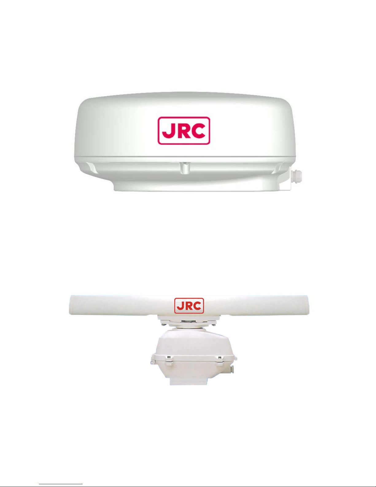
EQUIPMENT APPEARANCE
Scanner Unit Type NKE-2042 (2 feet)
Scanner Unit Type NKE-2062 (4 feet)
Page 15

X
Scanner Unit Type NKE-2102 (6 feet)
Processing Unit Type NDC-1260
Page 16

XI
Display Unit Type NWZ-146 (Landscape) and Keyboard Unit NCE-7640
Page 17

XII
Display Unit Type NWZ-146 (Portrait) and Keyboard Unit NCE-7640
Page 18

XIII
Contents
PREFACE ······························································································································I
Before Operation···················································································································II
Cautions to be used during operation··················································································III
EQUIPMENT APPEARANCE ···························································································· IX
Chapter 1 Introduction··································································· 1
1.1 Functions ································································································································1
1.2 Features··································································································································1
1.3 Composition····························································································································2
1.4 Configuration ··························································································································4
1.5 General System Diagram·····································································································11
Chapter 2 Names and Functions in the Keyboard Unit and the Menu Structure ·· 14
2.1 Functions of the Keyboard ···································································································14
2.1.1 Outline of the keyboard functions ···········································································14
2.1.2 Configuration and functions of the keys on keyboard ············································16
2.1.3 Structure and the functions of knobs ······································································19
2.1.4 Structure and functions of the jog dial·····································································20
2.1.5 Structure and functions of the track ball ·································································20
2.2 Description of Screen Display······························································································21
2.3 Menu Functions····················································································································23
2.3.1 Menu structure ········································································································23
General menu [MENU] (1/1 page)··········································································24
Installation setting menu [MENU] (1/3 pages)························································25
Installation setting menu [MENU] (2/3 pages)························································26
Installation setting menu [MENU] (3/3 pages)························································27
Menu by a direct key [TRAILS] (1/1 page) ·····························································28
Menu by a direct key [DIMM] ··················································································29
Menu by a direct key [ALARM ACK] ······································································30
Menu by a direct key [ATA] (1/3 pages)··································································31
Menu by a direct key [ATA] (2/3 pages)··································································32
Menu by a direct key [ATA] (3/3 pages)··································································33
Menu initialization by pressing a key at Power ON················································34
Setting menu language by pressing a key at Power ON ·······································34
Chapter 3 Operation Procedures················································ 35
3.1 Operation Flow ·····················································································································35
3.2 Power-on Operation ·············································································································36
3.2.1 Power-on and start ··································································································36
Page 19

XIV
1. Turning on the power [STBY] ············································································36
2. Transmitting [TX/PRF] ·······················································································36
3.2.2 Tuning [AUTO-TUNE] ·····························································································36
1. Switching the tuning mode·················································································36
2. Turning the tuning control [AUTO-TUNE]··························································36
3.2.3 Observation and image adjustment [+RANGE-] ····················································36
3.2.4 Data acquisition and measuring ·············································································36
3.2.5 Operation termination and stop [STBY], [TX/PRF]·················································37
1. Canceling transmission [STBY] ·········································································37
2. Turning off the power ·························································································37
3.3 Preparation for Observation·································································································38
3.3.1 Changing the brightness of the LCD ······································································38
3.3.2 Changing the brightness of the keyboard [DIMM]··················································38
3.3.3 Switching the display language [DIMM]··································································38
3.3.4 Setting the volume of the buzzer [ALARM ACK]····················································39
3.3.5 Switching the day/night mode [DIMM] ····································································40
1. Switching the day/night mode [DIMM]·······························································40
2. Switching the display color [DIMM]····································································40
3. Switching the brightness of the screen [DIMM]·················································41
3.4 Basic Operation····················································································································43
3.4.1 Transmitting [TX/PRF]·····························································································43
3.4.2 Halting transmission [STBY] ···················································································43
3.4.3 Changing the range [+RANGE-] ·············································································43
3.4.4 Erasing/displaying the fixed range marker [RR/HL] ···············································43
3.4.5 Erasing the ship's heading marker [RR/HL] ···························································43
3.4.6 Tuning······················································································································43
3.4.7 Adjusting sensitivity [GAIN/PL] ···············································································43
3.5 General Operation················································································································44
3.5.1 Eliminating radar interference [MENU] ···································································44
3.5.2 When it is raining or snowing [AUTO-RAIN]···························································45
3.5.3 When the sea is rough [AUTO-SEA] ······································································46
3.5.4 Using the trackball [TRACK BALL] ·········································································47
3.5.5 Using VRM [VRM1/VRM2], [JOG DIAL]·································································48
1. Selecting VRM#1/VRM#2 [VRM1/VRM2] ·························································48
2. Operating VRM#1/VRM#2 [VRM1/VRM2]························································48
3. Erasing VRM#1/VRM#2 [VRM1/VRM2]····························································48
4. Measuring the distance from own ship using VRM#1 [VRM1/VRM2]··············49
5. Measuring the distance from own ship using VRM#2 [VRM1/VRM2] ············49
6. Setting KM as range units··················································································50
3.5.6 Using EBL (electronic bearing cursor) [EBL1/EBL2], [TRACK BALL]···················51
1. Selecting EBL#1/EBL#2 [EBL1/EBL2] ······························································51
2. Operating EBL#1/EBL#2 [EBL1/EBL2]·····························································51
3. Erasing EBL#1/EBL#2 [EBL] ·············································································51
4. Measuring the bearing from own ship using EBL#1 [EBL1/EBL2]···················52
5. Measuring the bearing from own ship using EBL#2 [EBL1/EBL2]···················52
Page 20

XV
6. Using EBL2 as a floating EBL ···········································································52
7. Setting EBL display ····························································································53
3.5.7 Changing the bearing presentation method of the PPI screen [AZI MODE]·········54
3.5.8 Changing the center of the PPI screen [OFFCENT] ··············································55
1. Setting a position to which the center is moved ················································55
2. Canceling the position as the new center··························································55
3. Continuously moving the center ········································································56
4. Canceling the position as the new center··························································56
3.5.9 Using the trail display function [TRAILS] ································································56
1. Setting the trail display function to ON/OFF [TRAILS]······································56
2. Setting a trail interval [TRAILS]··········································································57
3. Clearing stored trail data [TRAILS] ····································································57
4. Setting a trail reference level (trail threshold) [TRAILS] ····································57
5. Setting a trail storage suppression distance [TRAILS]······································58
6. Setting a range trail storage [TRAILS]·······························································58
3.5.10 Using the target expansion function [MENU] ·························································59
1. Setting the target expansion function ································································59
2. Canceling the target expansion function ···························································59
3.5.11 Changing the transmitter pulse length [GAIN/PL] ··················································59
Changing the pulse length ······················································································60
3.5.12 Using the zoom function [MENU] ···········································································60
1. Setting the zoom function ··················································································60
2. Canceling the zoom function ·············································································60
3.5.13 Highlighting a target by decreasing unnecessary noise (image processing) [MENU] ·······61
1. Setting image processing [MENU] ····································································61
2. Canceling image processing [MENU] ·······························································62
3. Setting an image processing range [MENU]·····················································62
3.5.14 Switching true/relative motion display [TM/RM] ·····················································63
1. Switching the motion mode ···············································································63
2. Resetting own ship's position in true motion display (TM) ································63
3.5.15 Suppressing the power consumption of the radar [MENU] ···································65
1. Using the intermittent transmitting function [MENU] ·········································65
2. Canceling the intermittent transmitting function [MENU] ··································65
3. Setting the period of the transmitting state (the number of antenna rotations) [MENU] ·······65
4. Setting the period of the standby state [MENU]················································66
3.5.16 Monitoring the heading of other ships (targets) [ALARM ACK] ·····························67
1. Using the radar alarm [ALARM ACK]································································67
2. Canceling the radar alarm function····································································67
3. Creating a radar guard zone [ALARM ACK] ·····················································67
4. Setting a radar guard zone [ALARM ACK]························································68
5. Setting a radar guard zone detection level [ALARM ACK] ·······························68
3.5.17 Resetting an alarm (stopping a warning) [ALARM ACK] ·······································69
3.5.18 Displaying parallel line cursors [MENU], [VRM], [EBL] ··········································69
3.5.19 Using the MOB function [MOB]···············································································70
1. Displaying the MOB mark ··················································································70
Page 21

XVI
2. Erasing the MOB mark ······················································································70
3.5.20 Using the WAYPOINT function [MENU]·································································71
1. Displaying WAYPOINT ······················································································71
2. Erasing WAYPOINT···························································································71
3.5.21 Own ship display function [MENU] ·········································································72
Switching own ship display ·····················································································72
3.5.22 Function to convert time difference display to latitude/longitude display [MENU] ······72
1. Setting the LORAN chain (base station number) ············································72
2. Setting time difference (TD1 or TD2)·································································73
3. Setting the correction value (of TD1 or TD2) ····················································73
3.5.23 Cursor/own-ship position output function [CSR POS]············································73
3.6 Use of Function Keys ···········································································································75
3.6.1 Overview··················································································································75
3.6.2 Operation procedures ·····························································································76
1. Calling a function································································································76
2. Changing the setting of a function key ······························································76
3. Changing a function key title··············································································76
4. Initializing the setting of a function key (Returning to the factory setting)·········77
Function key menu lists (display only)····································································78
3.7 Other Procedures Required·································································································79
3.7.1 Confirming software versions [MENU]····································································79
3.7.2 Confirming the operating status of connected units [MENU] ·································79
3.7.3 Displaying magnetron current [MENU] [+RANGE-] ···············································80
3.7.4 Confirming error logs [ALARM ACK] ······································································81
3.7.5 Clearing the error log [ALARM ACK] ······································································82
3.7.6 Operating the self-diagnostic function [MENU] ······················································82
3.7.7 Displaying the help menu························································································82
3.7.8 Replacing the battery (BT1) ····················································································83
3.7.9 Procedure if an incomprehensible symptom occurs during use of the radar ········84
3.8 Options ·································································································································85
3.8.1 Operating a second keyboard unit [GAIN/PL] [JOG DIAL] ····································85
Chapter 4 How to Interpret the PPI Screen ································ 87
4.1 Height of and the Distance to the Target ·············································································87
Distance and Target ································································································87
4.2 Returns from a Target···········································································································88
4.3 Propagation Path of Radio Waves·······················································································88
4.3.1 Sea returns ··············································································································89
4.3.2 False echoes ···········································································································89
4.4 Display of Radar Transponder·····························································································91
Chapter 5 Maintenance and Inspection······································ 92
5.1 General Maintenance···········································································································92
Page 22

XVII
5.2 Scanner Unit·························································································································93
5.3 Display Unit···························································································································93
5.4 Special Parts·························································································································94
5.5 Circuit Blocks for Repair·······································································································95
5.6 Actions to Deal with Abnormalities and Breakdown····························································96
Chapter 6 After-sales Service ····················································· 97
When asking for repair ····························································································97
Recommendation of maintenance inspection ························································97
RADAR FAILURE CHECKLIST ·············································································98
Chapter 7 Disposal······································································ 99
7.1 Equipment Disposal ·············································································································99
7.2 Disposal of Used Batteries···································································································99
7.3 Disposal of Used Magnetron································································································99
Chapter 8 Specifications ··························································· 100
8.1 General Specifications ·······································································································100
8.2 Scanner Unit Specification·································································································101
8.2.1 Scanner unit (NKE-2042 : Redome type)·····························································101
8.2.2 Scanner unit (NKE-2062 : 6kW rotation type) ······················································101
8.2.3 Scanner unit (NKE-2102 : 10kW rotation type) ····················································102
8.3 Processing Unit Specifications···························································································103
8.4 Keyboard Unit Specifications ·····························································································105
8.5 Display Unit Specifications·································································································106
8.6 Option ·································································································································107
8.6.1 Interunit cable ········································································································107
8.6.2 Rectifier unit···········································································································107
8.6.3 Flash mounting kit ·································································································107
8.6.4 MARPA ··················································································································107
8.6.5 NSK unit·················································································································107
8.6.6 Sub indicator unit signal out ··················································································108
8.6.7 Sub keyboard unit ·································································································108
8.7 Rectifier·······························································································································109
8.8 Cable Length between Equipment Units ···········································································109
Chapter 9 Installation··································································110
This chapter has been written for the service technicians to read in case of installation.
9.1 General ·······························································································································110
9.2 Installing the Scanner Unit ································································································· 111
9.2.1 Selecting the installation location ·········································································· 111
Page 23

XVIII
9.2.2 Installation procedure···························································································· 113
1. Stand ················································································································113
2. Suspending the Scanner ················································································· 114
3. Paint ·················································································································114
4. Magnetism········································································································ 114
9.2.3 Connection of cables to be assembled································································· 115
1. Radome scanner unit (NKE-2042) ·································································· 115
2. Rotary scanner unit (NKE-2062/NKE-2102) ··················································· 117
9.3 Installing an Indicator Unit ·································································································· 119
9.3.1 Specifying the installation position ········································································119
9.3.2 Installation method ································································································119
9.3.3 Rear of the processing unit ···················································································120
9.3.4 Signals of option connectors ·················································································121
9.3.5 Installing and display unit ······················································································123
1. Setting vertically or horizontally ·······································································123
2. Connecting cables ···························································································123
9.3.6 Installing a keyboard unit·······················································································125
Connecting a cable ·······························································································125
9.3.7 Attaching a power cable (CFQ-6911-5)································································126
9.3.8 Attaching a cable between a processing unit and a scanner unit (CFQ-6912-20/30) ·····129
9.3.9 Connecting a GPS receiver and NMEA equipment ·············································131
1. Connecting GPS receiver of JRC····································································131
2. Connecting another manufacturer's GPS receiver or NMEA data output equipment ·······131
3. NMEA0183 standard input/output sentences ·················································133
9.3.10 Connecting a GPS compass (JLR-10) ·································································134
1. Using a dedicated cable ··················································································134
2. When not using a dedicated cable ··································································135
9.3.11 Connecting an electromagnetic compass ····························································136
9.3.12 Connecting gyro ····································································································137
1. Connections to an external buzzer ··································································139
2. Connections to a gyro and log ·········································································139
9.3.13 Connecting a PC plotter and NMEA equipment···················································146
1. Outputting NMEA0183 data to a PC plotter (RS232C output) ·······················146
2. Outputting NMEA0183 data to NMEA equipment (RS422 output) ················146
3. Switching RS232C/RS422 signal output·························································147
9.3.14 Connecting external buzzers ················································································148
9.4 Changing Ship's Power······································································································149
1. Display··············································································································149
2. Scanner unit ·····································································································149
9.5 Checking and Adjustment After Installation·······································································150
9.5.1 Checking after installation ·····················································································150
9.5.2 Checking operation ·······························································································150
9.5.3 Various adjustments······························································································150
9.5.4 Rectifier··················································································································151
9.6 Adjustment··························································································································152
Page 24

XIX
9.6.1 General adjustment·······························································································152
9.6.2 Adjusting a scanner unit························································································152
1. Adjusting AVR output voltage of a modulator··················································152
2. Adjusting a tuning indication level of a receiver ··············································152
9.6.3 Adjusting an indicator unit ·····················································································153
Adjusting AVR output ····························································································153
9.7 Initialization ·························································································································154
9.7.1 Adjusting a receiver [+RANGE-] [TX/PRF] [AUTO-TUNE] [MENU] ····················155
1. Tuning preset ···································································································155
2. Center frequency adjustment ··········································································155
3. Tuning indicator level adjustment ····································································156
9.7.2 Noise level adjustment [MENU] ············································································157
9.7.3 Azimuth adjustment [TM/RM] [AZI MODE] [MENU] ············································157
9.7.4 0 mile adjustment [TM/RM] [AZI MODE] [MENU] ················································158
9.7.5 Setting a scanner unit height [MENU] ··································································158
9.7.6 Setting a gyro value [MENU] [AZI MODE]····························································159
9.8 Various Initial Settings ········································································································160
9.8.1 Sensitivity preset [AUTO-SEA] [AUTO-RAIN] [GAIN/PL] [MENU] ······················160
9.8.2 Sea clutter preset [+RANGE-] [AUTO-TUNE] [AUTO-SEA] [AUTO-RAIN] [GAIN/PL] [MENU] ·······160
9.8.3 Control of main bang [+RANGE-] [AUTO-TUNE] [AUTO-SEA] [AUTO-RAIN] [GAIN/PL] [MENU] ···161
9.8.4 Setting a close range dynamic range [MENU] ·····················································162
9.8.5 Setting a video gradation level [MENU] ································································163
9.8.6 Setting video noise suppression display [MENU]·················································163
9.8.7 Setting a small target detection mode [MENU] ····················································164
9.8.8 Setting a float mode [MENU] ················································································165
9.8.9 Setting an inference suppression function level [MENU] ·····································165
9.8.10 Setting a short distance dynamic range [MENU] ·················································166
9.8.11 Setting a value of the target expansion function [MENU] ····································166
9.8.12 Setting target expansion function control [MENU] ···············································167
9.8.13 Setting a sensitivity correction value [MENU]·······················································167
9.8.14 Setting transmission power control [MENU]·························································168
9.8.15 Setting a scanner unit rotation speed [MENU] ·····················································168
9.8.16 Setting information in a GPS receiver···································································169
1. Setting the position of your own ship [MENU]·················································169
2. Setting a height of own ship [MENU]·······························································169
3. Setting geodetic information [MENU] ······························································170
4. Setting a position fixing mode [MENU]····························································173
5. Setting a HDOP level [MENU] ·········································································173
6. Setting an averaging level [MENU] ·································································174
7. Setting a prohibited satellite number [MENU] ·················································174
8. GPS receiver master reset [MENU] ································································175
9. Sending updated set values [MENU] ······························································175
10. Setting UTC time [MENU]················································································176
11. Setting a UTC time difference [MENU]····························································176
12. Sending updated setting values [MENU] ························································176
Page 25

XX
9.8.17 Setting information in a DGPS receiver································································178
1. Setting a DPGS mode [MENU] ·······································································178
2. Setting a frequency used by a beacon station [MENU] ··································178
3. Setting a baud rate for communication with a beacon station [MENU]··········178
4. Setting a DPGS mode [MENU] ·······································································179
5. Sending updated setting values [MENU] ························································179
9.8.18 Setting information in a WAAS receiver································································180
1. Setting a WAAS mode [MENU]·······································································180
2. Setting a position fixing satellite [MENU]·························································180
3. Setting information whether a prohibited satellite can be used [MENU] ········180
4. Setting a satellite number [MENU] ··································································181
5. Sending updated setting values [MENU] ························································181
9.8.19 Displaying GPS receiving status···········································································182
9.8.20 Initializing ATA [MENU] ·························································································182
9.8.21 Setting a course data input type [MENU] ·····························································183
9.8.22 Setting manual course data [MENU] ····································································184
9.8.23 Setting a speed data input type [MENU] ······························································184
9.8.24 Setting manual speed data [MENU] ·····································································185
9.8.25 Setting own ship's position input selection [MENU] ·············································185
9.8.26 Setting own ship's position input [MENU]·····························································186
9.8.27 Setting a compass input baud rate [MENU] ·························································186
9.8.28 Setting connection of the 2nd keyboard [MENU] ·················································187
9.8.29 Setting a NMEA data output frequency [MENU]··················································187
9.8.30 Setting selection of a magnetic azimuth sensor correction value [MENU]··········188
9.8.31 Setting manual data for a compass correction value [MENU] ·····························189
9.8.32 Setting a PC output baud rate [MENU]·································································189
9.8.33 Setting a keyboard port baud rate [MENU] ··························································189
9.8.34 Setting a display direction of the indicator [MENU] ··············································190
9.8.35 Setting a display timing of the indicator [MENU] ··················································190
9.8.36 Setting reading/writing setting values to non-initialization memory [MENU]········191
9.8.37 Initializing a menu storage area [MENU]······························································192
9.8.38 Displaying simulator images ·················································································192
9.8.39 Special mode·········································································································193
9.9 Resetting Adjustments to the Initial State··········································································194
9.10 Maintenance·······················································································································195
9.10.1 General maintenance····························································································195
1. Cleaning the equipment···················································································195
2. Checking the tightening of screws···································································195
3. Checking connections······················································································195
9.10.2 Scanner unit ··········································································································196
1. Radiation section······························································································196
2. Rotation driving section····················································································197
9.10.3 Display···················································································································198
Cleaning display ····································································································198
Page 26

XXI
Attached Figures
[Fig. 101 INTERCONNECTION DIAGRAM OF JMA-5104]
[Fig. 102 INTERCONNECTION DIAGRAM OF JMA-5106]
[Fig. 103 INTERCONNECTION DIAGRAM OF JMA-5110]
[Fig. 104 PRIMARY POWER SYSTEM DIAGRAM OF JMA-5104]
[Fig. 105 PRIMARY POWER SYSTEM DIAGRAM OF JMA-5106]
[Fig. 106 PRIMARY POWER SYSTEM DIAGRAM OF JMA-5110]
[Fig. 107 INTERNAL CONNECTION OF SCANNER UNIT NKE-2042]
[Fig. 108 INTERNAL CONNECTION OF SCANNER UNIT NKE-2062]
[Fig. 109 INTERNAL CONNECTION OF SCANNER UNIT NKE-2102]
[Fig. 110 CIRCUIT DRAWING OF MODULATOR UNIT CME-322]
[Fig. 111 CIRCUIT DRAWING OF MODULATOR UNIT CME-323]
[Fig. 112 CIRCUIT DRAWING OF POWER SUPPLY UNIT CBD-1645 (1/2)]
[Fig. 113 CIRCUIT DRAWING OF POWER SUPPLY UNIT CBD-1645 (2/2)]
[Fig. 114 CIRCUIT DRAWING OF MODULATOR UNIT CPA-248]
[Fig. 115 INTERNAL CONNECTION OF DISPLAY UNIT NCD-4310]
[Fig. 116 CIRCUIT DRAWING OF POWER SUPPLY UNIT CBD-1638]
Page 27

Page 28

1
Chapter 1 Introduction
1.1 Functions
This device is a marine radar device that utilizes a scanner unit including transmitter and
receiver and 10.4 inch liquid crystal display unit and uses a compact raster scan method for
achieving a fully semiconductor adopted (except for special electron tubes) system.
This equipment comprises radar as defined in the Wireless Telegraphy Act.
1.2 Features
Enhanced fundamental performance of the radar
Through switching among 4 steps in terms of pulse width/cycle switching of frequency and
switching among 3 steps in receiver bandwidth, enhanced fundamental performance of the
radar has been achieved towards display of clearer and high quality images. Moreover,
through the incorporation of advanced digital signal processing, performance in target
de-tection during increment weather has been improved.
Confirmation of the ship's position and identifying the waypoint at a glance
Through connecting to external navigation equipment such as GPS, the location of the ship
(numerical values) or a mark on the waypoint may be displayed on the screen. This allows for
confirmation of the difference between the waypoint and the ship's heading at a glance.
High operability
A jog dial has been incorporated for simple operation of menu selections, EBL/VRM.
The track ball may also be used to capture the MARPA target in a simple manner.
A system for the direct display of menu items that are frequently used with dedicated keys has
been adopted.
Page 29

2
1.3 Composition
Radar configuration and ship's power
Comprehensive
model name
Scanner unit
Processing
unit
Keyboard
unit
Display unit Ship's power supply
JMA-5104
JMA-5106
JMA-5110
NKE-2042
NKE-2062
NKE-2102
NDC-1260 NCE-7640 NWZ-146
DC (12V/24V/32V )
DC (12V/24V/32V)
DC (24V/32V)
When an optional rectifier unit is used: (AC100V/110V/115V/200V/220V/230V) 50/60Hz single
phase
Rectifier unit model name (optional) : NBA-797
Note
When AC power supply is used, an optional rectifier unit is necessary.
The English presentation of the nameplate of each unit is as follows.
SCANNER UNIT
PROCESSING UNIT
KEYBOARD UNIT
DISPLAY UNIT
RECTIFIER UNIT
Attachments
Item name Quantity JRC code Remarks
Instruction manual 1 7ZPRD0590 This manual (English)
Cable between a scanner
unit and a processing unit
1 CFQ6912-20
19-core composite cable
Standard length 20m
Power cable 1 CFQ-6911-5 5m
Spare parts
Spare parts are provided for each of the indicator unit and the scanner unit.
The following table lists spare parts for each unit.
Spare parts for the indicator unit (7ZRD0010) included in the same package as the processing unit
Item name Quantity JRC code Remarks
Fuse (M60NR-10A) 3 5ZFAD00018 (Processing unit F1 : 10A)
6-pin connector 1 5JCDX00014 For NMEA data communication
8-pin connector 1 5JCDX00015 For NMEA data communication
Note
Only a 10A fuse is available for processing unit F1 (fuse for the indicator unit power) regardless of the
input power voltage and transmission output.
Page 30

3
NKE-2042 (spare parts for 4kw scanner unit) included in the same package as scanner unit 7ZXRD0012
Item name
(model name)
Quantity JRC code Remarks
Fuse (SM6.3) 4 5ZFAD00543
For modulator
(processing unit F2 : 6.3A)
12V
input
Not required −
For motor
(processing unit F3:)
Fuse (SM3.15) 4 5ZFAD00359
For modulator
(processing unit F2 : 3.15A)
24/32V
input
Not required −
For motor
(processing unit F3:)
Note
For the 4kw scanner unit, insertion of F3 in the processing unit (fuse for motor) is not required since the
power supply is shared between the modulator and the motor. Therefore, there are no spare parts.
NKE-2062 (spare parts for 6kw scanner unit) included in the same package as scanner unit 7ZXRD0013
Item name
(model name)
Quantity JRC code Remarks
Fuse (SM6.3) 4 5ZFAD00543
For modulator
(processing unit F2 : 6.3A)
12V
input
Fuse (SM5) 4 5ZFAD00393
For motor
(processing unit F3 : 5A)
Fuse (SM3.15) 4 5ZFAD00359
For modulator
(processing unit F2 : 3.15A)
24/32V
input
Fuse (SM5) 4 5ZFAD00393
For motor
(processing unit F3 : 5A)
Carbon brush
(54531-01)
2 BRXP05247
NKE-2102 (spare parts for 10kw scanner unit) included in the same package as scanner unit 7ZXRD0014
Item name
(model name)
Quantity JRC code Remarks
Fuse (SM5) 4 5ZFAD00393
For modulator
(processing unit F2 : 5A)
24/32V
input
Fuse (SM8) 4 5ZFAD00544
For motor
(processing unit F3 : 8A)
Carbon brush
(54583-01)
2 BRSW00101
Page 31

4
1.4 Configuration
Fig. 1.1 OUTLINE DRAWING OF SCANNER UNIT NKE-2042
Page 32

5
Fig. 1.2 OUTLINE DRAWING OF SCANNER UNIT NKE-2062
Page 33

6
Fig. 1.3 OUTLINE DRAWING OF SCANNER UNIT NKE-2102
Page 34

7
Fig. 1.4 OUTLINE DRAWING OF PROCESSING UNIT NDC-1260
Page 35

8
Fig. 1.5 OUTLINE DRAWING OF KEYBOARD UNIT NCE-7640
Page 36

9
Fig. 1.6 OUTLINE DRAWING OF DISPLAY UNIT NWZ-146 (LANDSCAPE)
Page 37

10
Fig. 1.7 OUTLINE DRAWING OF DISPLAY UNIT NWZ-146 (PORTRAIT)
Page 38

11
1.5 General System Diagram
Fig. 1.8 GENERAL SYSTEM DIAGRAM OF JMA-510
4
NOTES :
ELIMINATING THE INTERFERENCE ON FREQUENCIES USED FOR MARINE
COMMUNICATIONS AND NAVIGATION DUE TO OPERATION OF THE RADAR.
ALL CABLES OF THE RADAR ARE TO BE RUN AWAY FROM THE CABLES OF RADIO
EQUIPMENT.
(EX. RADIOTELEPHONE.COMMUNICAITONS RECEIVER AND DIRRECTION FINDER.ETC.)
ESPECIALLY INTER-WIRING CABLES BETWEEN SCANNER UNIT AND DISPLAY UNIT OF
THE RADAR
SHOULD NOT BE RUN PARALLEL WITH THE CABLES OF RADIO
EQUIPMENT.
Interunit cable (20m)
CFQ-6912-20
GPS Receiver or
NMEA signal input
GPS COMPASS(JLR-10)
or Magnetic compass
Rectifier
(Option)
NBA-797
AC100/110/115/
200/220/230V, single phase
Power cable (for 5m)
CFQ-6911-5
From DC10.8V to DC42V
(Cable length 20m)
From DC21.6V to DC42V
(Cable length 30m)
Scanner unit (NKE-2042)
Processing unit (NDC-1260)
NMEA signal out (for other equipment)
NMEA data: GLL, etc.
Cursor data: RSD
Own ship data: OSD
MARPA data out: TTM
Keyboard unit (NCE-7640)
Display unit (NWZ-146)
Indicator unit (NCD-4310)
VGA signal out
10.4 inches
color LCD
EXT.Buzz signal out
GYRO in
(SYNC/STEP)
LOG in
(SYNC/STEP)
NSK unit
(Option)
NCT-4106
Sub keyboard unit
(NCE-7640)
Slave Indicator signal out
5m
5m
Option
MARPA
Unit (Option)
NCA-868
PC
plotter
5m
Control unit (NCM-770)
H-7ZCNA0855
H-7ZCNA0855
H-7ZCRD0853
CFQ-6900(power cable)
CFQ-6901(signal cable)
Landscape or Portrait
27rpm
4kW
2ft
H-CFQ-6934
Page 39

12
Fig. 1.9 GENERAL SYSTEM DIAGRAM OF JMA-5106
NOTES :
ELIMINATING THE INTERFERENCE ON FREQUENCIES USED FOR MARINE
COMMUNICATIONS AND NAVIGATION DUE TO OPERATION OF THE RADAR.
A
LL CABLES OF THE RADAR ARE TO BE RUN AWAY FROM THE CABLES OF RADIO
EQUIPMENT.
(EX. RADIOTELEPHONE.COMMUNICAITONS RECEIVER AND DIRRECTION FINDER.ETC.)
ESPECIALLY INTER-WIRING CABLES BETWEEN SCANNER UNIT AND DISPLAY UNIT OF
THE RADAR
SHOULD NOT BE RUN PARALLEL WITH THE CABLES OF RADIO
EQUIPMENT.
GPS Receiver or
NMEA signal input
GPS COMPASS(JLR-10)
or Magnetic compass
Rectifier
(Option)
NBA-797
AC100/110/115/
200/220/230V, single phase
Processing unit (NDC-1260)
NMEA signal out (for other equipment)
NMEA data: GLL, etc.
Cursor data: RSD
Own ship data: OSD
MARPA data out: TTM
27rpm
6kW
4ft/6ft
Scanner unit (NKE-2062)
Interunit cable (20m)
CFQ-6912-20
Keyboard unit (NCE-7640)
Display unit (NWZ-146)
Indicator unit (NCD-4310)
VGA signal out
10.4 inches
color LCD
EXT.Buzz signal out
GYRO in
(SYNC/STEP)
LOG in
(SYNC/STEP)
NSK unit
(Option)
NCT-4106
Sub keyboard unit
(NCE-7640)
Slave Indicator signal out
5m
5m
Option
MARPA
Unit (Option)
NCA-868
PC
plotter
5m
Control unit (NCM-770)
H-7ZCNA0855
H-7ZCNA0855
H-7ZCRD0853
CFQ-6900(power cable)
CFQ-6901(signal cable)
Landscape or Portrait
H-CFQ-6934
Power cable (for 5m)
CFQ-6911-5
From DC10.8V to DC42V
(Cable length 20m)
From DC21.6V to DC42V
(Cable length 30m)
Page 40

13
Fig. 1.10 GENERAL SYSTEM DIAGRAM OF JMA-5110
NOTES :
ELIMINATING THE INTERFERENCE ON FREQUENCIES USED FOR MARINE
COMMUNICATIONS AND NAVIGATION DUE TO OPERATION OF THE RADAR.
ALL CABLES OF THE RADAR ARE TO BE RUN AWAY FROM THE CABLES OF RADIO
EQUIPMENT.
(EX. RADIOTELEPHONE.COMMUNICAITONS RECEIVER AND DIRRECTION FINDER.ETC.)
ESPECIALLY INTER-WIRING CABLES BETWEEN SCANNER UNIT AND DISPLAY UNIT OF
THE RADAR
SHOULD NOT BE RUN PARALLEL WITH THE CABLES OF RADIO
EQUIPMENT.
27rpm
10kW
6ft
GPS Receiver or
NMEA signal input
GPS COMPASS(JLR-10)
or Magnetic compass
Rectifier
(Option)
NBA-797
AC100/110/115/
200/220/230V, single phase
Scanner unit (NKE-2102)
Power cable (for 5m)
CFQ-6911-5
From DC21.6V to DC42V
Processing unit (NDC-1260)
NMEA signal out (for other equipment)
NMEA data: GLL, etc.
Cursor data: RSD
Own ship data: OSD
MARPA data out: TTM
Interunit cable (20m)
CFQ-6912-20
Keyboard unit (NCE-7640)
Display unit (NWZ-146)
Indicator unit (NCD-4310)
VGA signal out
10.4 inches
color LCD
EXT.Buzz signal out
GYRO in
(SYNC/STEP)
LOG in
(SYNC/STEP)
NSK unit
(Option)
NCT-4106
Sub keyboard unit
(NCE-7640)
Slave Indicator signal out
5m
5m
Option
MARPA
Unit (Option)
NCA-868
PC
plotter
5m
Control unit (NCM-770)
H-7ZCNA0855
H-7ZCNA0855
H-7ZCRD0853
CFQ-6900(power cable)
CFQ-6901(signal cable)
Landscape or Portrait
H-CFQ-6934
Page 41

14
Chapter 2
Names and Functions in the Keyboard
Unit and the Menu Structure
2.1 Functions of the Keyboard
The normal operations of this radar equipment can be performed using the switches, volume knob,
jog dial, and track ball on the keyboard unit.
The operations are simple, however it is important to understand that the function of each
operation unit is to obtain the required information on the LCD screen of the display unit.
2.1.1 Outline of the keyboard functions
The keyboard unit consists of the following four main components.
[Key], [Knob], [Jog dial], and [Track ball]
Each of these components is described below.
The correspondence between the operation method and the function is described below.
The notation enclosed by brackets [ ] indicates a key, a knob, a jog dial, or a track ball on the
keyboard.
Example of a key : [CLEAR]
Example of a knob : [AUTO-SEA]
Jog dial : [JOG DIAL]
Track call : [Track Ball]
A boxed notation ( XXXX ) indicates display of a menu item.
Example : BASIC
Page 42

15
(1)
Tuning knob
Rain/snow reflection knob
Sea clutter knob
Sensitivity knob
(2) (3) (5) (8) (14) (17) (18) (19)
Track ball
(15)
Jog dial
(4) (6) (7) (9) (10) (11) (13) (12) (16)
Page 43

16
2.1.2 Configuration and functions of the keys on keyboard
Nineteen keys on keyboard are available in total.
The keys on keyboard are classified into two major types based on the operation mode; keys in
short mode
short modeshort mode
short mode
and keys in long mode
long modelong mode
long mode.
A short mode is mainly used for setting key functions to ON/OFF and a long mode is used for
displaying detail menus related to the key functions.
This method enables users to set related key functions directly with fewer keys.
A short mode refers to the pressing of a key for short time and a long mode refers to the pressing
of a key for two seconds or more continuously.
The functions of the keys in short mode and those in long mode are described below.
(1) [STBY] key
Short mode : Power ON
Long mode : The power is turned off when this key is pressed together with [TX/PRF] key in
long mode.
(2) [TX/PRF] key
Short mode : When this key is pressed from a standby state, the equipment is set to a
transmission state. When this key is pressed in a transmission state, the
repetition frequency is changed.
Long mode : The power is turned off when this key is pressed together with the [STBY] key
in long mode.
(3) [EBL1/EBL2] key
Short mode : EBL ON/OFF of EBL
Long mode : Switches EBL1/EBL2.
(4) [VRM1/VRM2] key
Short mode : VRM ON/OFF
Long mode : Switches VRM1/VRM2
(5) [ALARM ACK] key
Short mode : Stops alarm buzzer.
Long mode : Displays alarm detail setting/error log.
(6) [MOB] key
Short mode : Starts the MOB function.
Long mode : Stops the MOB function.
(7) [CLEAR] key
In short mode, the operation varies depending on whether it is during menu operation and
other states, which are described later.
Page 44

17
During menu operation
Short mode : During item selection on a menu, this key stops the current item selection.
When item selection is completed, this key returns control to the menu one
level above.
State other than menu operation
Short mode : When this key is pressed while the cursor overlaps with the ATA symbol, this
operation erases the ATA symbol.
When the key is pressed while cursor does not overlap with the ATA symbol, the
target of the symbol number that is selected by numeric display is erased.
Long mode : Erases the entire ATA symbol.
(8) [DIMM] key
Short mode : Changes the brightness of the key on the keyboard unit.
Long mode : Displays a day/night menu.
(9) [FUNC] key
Short mode : Switches the function setting.
Long mode : Displays a function setting menu.
(10) [OFF CENT] key
Short mode : Moves the center to the cursor position/returns to the center.
Long mode : Continuously moves the center.
(11) [RR/HL] key
Short mode : FIXM ON/OFF
Long mode : Sets the display of a highlighted line of the bow of the ship to OFF.
(12) [TM/RM] key
Short mode : Switches TM/RM/CTM (unlimited TM).
Long mode : Applies manual reset in TM mode.
(13) [AZI MODE] key
Short mode : Switches an azimuth mode (HUP/NUP/CUP).
Long mode : Displays a gyro setting menu.
(14) [TGT DATA] key
Short mode : Displays target information or the next target information.
(When a target is being displayed)
Long mode : Set ATA display to ON/OFF.
Switches the display when MOB/WPT is set to ON.
MOB → ATA → WPT → MOB
Page 45

18
(15) [TRAILS] key
Short mode :
Switches to time track/continuous track/time track + continuous track/non-display.
Long mode : Displays a track menu (track erase, track time setting change, and so on).
(16) [CSR POS] key
Short mode : Outputs the information of the bearing and distance from the current own
ship's position to cursor position. It is output by the serial communication from
the RS232C port.
Long mode : Outputs the information of the bearing and distance when the cursor is the own
ship's position. It is output by the serial communication from the RS232C port.
(Outputs "distance = 0NM", "bearing=0 degree").
(17) [+RANGE-] key
Short mode : Switches the range (+: range up, -: range down).
Long mode : Switches the continuous range (+: continuously range up, -: continuously range
down)
* When the [+RANGE-] key is pressed while the zoom function is ON, the zoom function is
automatically released.
(18) [ACQ/ENT] key
Short mode : Target capture
Long mode : ACQ mode menu
(19) [MENU] key
Short mode : Set a menu to ON/OFF.
Long mode : Set an initialization menu to ON/OFF
* Initialization refers to the settings made at installation.
Page 46

19
2.1.3 Structure and the functions of knobs
Four knobs are available.
The knobs are classified into three main modes based on the operation. One type is a knob
knob knob
knob
operation mode
operation modeoperation mode
operation mode and other two are a short mode
short modeshort mode
short mode and a long mode
long modelong mode
long mode, similar to the key operations.
In knob operation mode, the values change according to the rotation of the knob. The short mode
and the long mode are the same operation as for the keys.
The function of each knob is described below.
[AUTO-TUNE] knob
Short mode : Switches to automatic/manual.
Long mode : When the power supply is set to ON while this key is pressed, horizontal
orientation display is set (12 o'clock).
Knob operation : The equipment is tuned when the knob is set to the center.
[AUTO-RAIN] knob
Short mode : Switches to automatic/manual.
Long mode : When the power supply is set to ON while this key is pressed, vertical
clockwise rotation display is set (3 o'clock).
Knob operation : The control function reaches the maximum when the knob is turned to the
full position in the clockwise direction and the minimum when the knob is
turned to the full position in the anti-clockwise direction.
[AUTO-SEA] knob
Short mode : Switches to automatic/manual.
Long mode : When the power supply is set to ON while this key is pressed, horizontal
reverse orientation display is set (6 o'clock).
Knob operation : When the knob is turned to the full position in clockwise direction, the
control function reaches the maximum level and when the knob is turned
to the full position in the anti-clockwise direction, the control function
reaches the minimum level.
[GAIN/PL] knob
Short mode : Switches a transmission pulse width.
Long mode : Displays a panel 1/2 switching menu while the power is supplied.
When the power is not supplied, vertical anti-clockwise rotation display is
set if the power supply is set to ON (9 o'clock).
Knob operation : When the knob is turned to the full position in the clockwise direction, the
sensitivity reaches the maximum level and when the knob is turned to the
full position in the anti-clockwise direction, the sensitivity reaches the
minimum level.
Page 47

20
2.1.4 Structure and functions of the jog dial
Two jog dial operation modes are available.
One mode is roration mode
roration moderoration mode
roration mode
, and other mode is short mode
short modeshort mode
short mode.
Rotation mode : In this mode, items displayed on EBL/VRM/ATA display/menu changes when the
jog dial is turned. The cursor on the bottom-right of the screen and the
characters displayed on the right-hand side indicates which rotation mode is the
current mode.
Rotation modes an mode display
Purpose Mode name
Characters that are displayed on the
bottom-right of the screen
EBL setting EBL mode JOG EBL1*
VRM setting VRM mode JOG VRM1*
Switching MARPA value
data display
MARPA display mode JOG ATA
Menu display Menu selection mode JOG MENU
*At operation 1 and 2, EBL1, EBL2, VRM1, and VRM2 are displayed respectively.
Short mode : When menu display is not set, the mode is switched to EBL/VRM/ATA operation
mode whenever the jog dial is pressed.
This mode determines the menu of the line that was selected when a menu is
displayed.
(Same operation as
(Same operation as (Same operation as
(Same operation as [ACQ/ENT]))))
2.1.5 Structure and functions of the track ball
Normally [TRACK BALL] is used for operating a cross cursor.
When [TRACK BALL] is moved, the distance from own ship and the azimuth are displayed at the
bottom-left corner of the screen. When navigation equipment is connected, the latitude and
longitude are also displayed. When a MARPA function is attached, a required target can be
captured by moving the cross cursor by operating [TRACK BALL] to the target.
By pressing the [OFF CENT] key, the center of PPI can be moved to the cross cursor position.
By moving [TRACK BALL] while pressing the [OFF CENT] key in long mode, the center of PPI can
be moved to the position of [TRACK BALL] consecutively.
Page 48

21
2.2 Description of Screen Display
<Horizontal display>
Own ship information
Own ship course
Own ship speed
Position information/navigation equipment
Latitude
Longitude
EBL1 value display
EBL2 value display
VRM1 value display
VRM2 value display
ATA target information
Target number
Distance to the target
Azimuth to the target
Course of the target
Target speed
Closest approach distance of the target
Closest approach time of the target
Vector length
Various alarm display area
Distance range
Fixed distance scale interval
Transmission status display
Motion display
PPI azimuth display
Function setting status
Sea clutter/rain and snow reflection
suppression mode display
Guard zone operation displayed
Tune bar displa
y
Jog dial mode display
Zoom function display
Interference suppression function display
Target expansion function display
Correlation processing function display
Trail function display
Trail time display
Cursor information
Azimuth to the cursor
Distance to the cursor
Latitude to the cursor
Longitude to the cursor
Pulse width displa
y
Day/night mode displa
y
Page 49

22
<Vertical display>
Own ship information
Own ship course
Own ship speed
Position information/navigation equipment
Latitude
Longitude
EBL1 value display
EBL2 value display
VRM1 value display
VRM2 value display
ATA target information
Target number
Distance to the target
Azimuth to the target
Course of the target
Target speed
Closest approach distance of the target
Closest approach time of the target
Vector length
Various alarm display area
Cursor information
Azimuth to the cursor
Distance to the cursor
Latitude to the cursor
Longitude to the cursor
Function setting status
Sea clutter/rain and snow reflection
suppression mode display
Guard zone operation displayed
Pulse width displa
y
Tune bar displa
y
Jog dial mode displa
y
Trail time display
PPI azimuth display
Motion display
Transmission status display
Fixed distance scale interval
Distance range
Trail function display
Correlation processing function display
Target expansion function display
Interference suppression function display
Zoom function display
Day/night mode displa
y
Page 50

23
2.3 Menu Functions
This radar equipment has the functions available through menus in addition to the functions
available on the keyboard unit and volume knobs. This section describes the structure of the
menus, the functions, and the setting method.
2.3.1 Menu structure
This radar equipment can display information in Japanese, English, and other languages (French,
Spanish, Italian, Danish, and Norwegian) on the screen by switching.
●●●● See 3.3.3, "Switching the display language [DIMM]" for switching a display
language.
Opening a menu
Press the [MENU] key to display a menu.
Closing a menu
To close a menu, press the [MENU] key or keep pressing the [CLEAR] key until the menu is
closed.
Moving to a menu at a lower level
Menus are organized in a hierarchical structure. To move control to a menu at a lower level,
select the characters of a required menu item using [JOG DIAL] and press the [JOG DIAL] or
[ACQ/ENT] key. Consequently, the menu at the lower level is displayed.
Moving to a menu at an upper level
To return control to a menu at the immediate upper level, press the [CLEAR] key. The menu
at the immediate upper level is displayed.
Determining an item
To determine an item after changing the value using [TRACK BALL] or displaying the setting
item in reverse video, press the [JOG DIAL] or [ACQ/ENT] key.
Menu lists are described below.
Menus are classified into general function setting menus that are displayed by
pressing a key in short mode and setting menus at installation that are displayed
by pressing a key in long mode.
Page 51

24
General menu [MENU] (1/1 page)
1st level 2nd level
BASIC >
DISP OPTIONS >
TX PLAN >
INFORMATION >
HELP >
MENU
INTERFERENCE IR1
TGT EXPANSION OFF
PROCESS OFF
PROC SW RANGE 3.0
ECHO POWER FULL
ZOOM OFF
EBL BEARING TRUE
FROATING EBL OFF
PARALLEL LINE OFF
VRM1 UNITS NM
VRM2 UNITS NM
WAYPOINT OFF
POSITION LL
LL-TD CONV >
TX PLAN OFF
TX PERIOD 10 SCAN
STBY PERIOD 3 MIN
SOFTWARE VER.
PORT CONNECT
INITIALIZE ALL ACQENT+MENU
SELF TEST EBL+VRM
LANGUAGE DIMM
DISP MOUNT UP TUNE
DISP MOUNT R RAIN
DISP MOUNT REV SEA
DISP MOUNT L GAIN
INFORMATION
HELP
BASIC
DISP OPTIONS
TX PLAN
→ BASIC (3rd level menu available)
Sets operation and processing mainly related to radar images.
↑
Display method
Press [MENU] in short mode.
→ HELP
Displays explanation of keys and menu operation.
→ INFORMATION (3rd level menu available)
Displays the software version and operation status of the connected equipment.
→ TX PLAN (3rd level menu available)
Sets an intermittent transmission mode and detail operation.
→ DISP OPTIONS (3rd and 4th level menus are available)
Sets markers that are displayed in graphic mode and functions that displa
y
data from navigation equipment.
Page 52

25
Installation setting menu [MENU] (1/3 pages)
1st level 2nd level
GYRO SETTING
123.4°
RADAR >
GPS >
ATA SETTING >
DATA/IN OUT >
BAUD RATE >
DISPLAY MOUNT>
LCD SETTING >
BACKUP MEMORY>
INIT MENU >
INSTALLATION
GYRO SETTING 123.4°
SIMULATION OFF
RADAR >
GPS >
ATA SETTING >
DATA/IN OUT >
BAUD RATE >
DISPLAY MOUNT>
LCD SETTING >
BACKUP MEMORY>
INIT MENU >
GYRO SETTING 123.4°
SIMULATION OFF
OFF
INTERNAL
EXTERNAL
DATA/IN OUT >
BAUD RATE >
DISPLAY MOUNT>
LCD SETTING >
BACKUP MEMORY>
INIT MENU >
RADAR ADJUST >
RADAR ADJUST2>
RADAR SETTING>
ROT SPEED >
INSTALLATION
INSTALLATION
RADAR
→ GYRO SETTING
Sets gyro data.
↑
Display method
Press [MENU] in long mode.
→ RADAR ADJUST (3rd and 4th level menus available)
Sets basic information at installation of radar equipment such as tuning,
distance, and azimuth.
→ SIMULATION
Switches between a simulator mode and a normal mode alternately.
Page 53

26
Installation setting menu [MENU] continued (2/3 pages)
1st level 2nd level
GYRO SETTING 123.4°
SIMULATION OFF
RADAR >
GPS >
ATA SETTING >
DATA/IN OUT >
BAUD RATE >
DISPLAY MOUNT>
LCD SETTING >
BACKUP MEMORY>
INIT MENU >
INSTALLATION
GPS SETTING >
GPS SETTING2 >
DGPS SETTING >
WAAS SETTING >
GPS INFO >
ATA OFF
LEVEL H 64
LEVEL L 64
LEVEL G 64
VECTOR CONST 4
AUTO ACQ OFF
TEST VIDEO OFF
NUMBERING AUTO
GATE DISP OFF
COURSE IN COMPASS GYRO
MANUAL COURSE 000°
SPEED IN GPS BT
MANUAL SPEED 00.0 KT
POSITION IN GPS
MANUAL POS. N 36°36.000'
E136°36.000'
COMPASS PORT JLR-10(9600)
2ND PANEL DISABLE
NMEA OUT >
CALIBRATION
PC 4800
PANEL 4800
BAUD RATE
GPS
ATA SETTING
DATA/IN OUT
→ GPS SETTIGN (3rd and 4th level menus available)
Sets initial values in the GPS receiver.
↑
Display method
Press [MENU] in long mode.
→ BAUD RATE (3rd level menu available)
Sets a communication speed with a personal computer.
→ DATA/IN OUT (3rd and 4th level menus)
Sets information for receiving data from a sensor such as speed, course, an
d
position.
→ ATA SETTING (3rd level menu available)
Initializes the optional MARPA.
Page 54

27
Installation setting menu [MENU] Continued (3/3 pages)
1st level 2nd level
GYRO SETTING 123.4°
SIMULATION OFF
RADAR >
GPS >
ATA SETTING >
DATA/IN OUT >
BAUD RATE >
DISPLAY MOUNT HORIZONTAL
LCD SETTING >
BACKUP MEMORY>
INIT MENU >
INSTALLATION
GYRO SETTING 123.4°
SIMULATION OFF
RADAR >
GPS >
ATA SETTING >
DATA/IN OUT >
DISPLAY MOUNT
HORIZONTAL
VERTICAL-RIGHT
INVERSION
VERTICAL-LEFT
HS DISP START 143
VS DISP START 37
STORE >
LOAD >
DISPLAY MOUNT
LCD SETTING
BACKUP MEMORY
→ DISPLAY MOUNT
Sets a display orientation of the display unit.
↑
Display method
Press [MENU] in long mode.
→ BACKUP MEMORY
→ LCD SETTING (3rd level menu available)
Sets a display position of the LCD.
Page 55

28
Menu by a direct key [TRAILS] (1/1 page)
1st level 2nd level
TRAIL INTERVAL 6M
TRAIL REF LVL 8
TRAIL SUPRESS 0.0NM
TRAIL CLEAR OFF
RANGE TRAIL CLEAR
TRAILS
TRAIL INTERVAL 6M
6M 8
TRAIL SUPRESS 0.0NM
TRAIL CLEAR OFF
RANGE TRAIL CLEAR
TRAIL INTERVAL 6M
TRAIL REF LVL 8
8 0.0NM
TRAIL CLEAR OFF
RANGE TRAIL CLEAR
TRAIL INTERVAL 6M
TRAIL REF LVL 8
TRAIL SUPRESS 0.0NM
0.0NM OFF
RANGE TRAIL CLEAR
TRAIL INTERVAL 6M
TRAIL REF LVL 8
TRAIL CLEAR 0.0NM
OFF OFF
ON CLEAR
TRAIL INTERVAL 6M
TRAIL REF LVL 8
RANGE TRAIL 0.0NM
CLEAR OFF
KEEP CLEAR
TRAILS
TRAILS
TRAILS
TRAILS
TRAILS
→ TRAIL SUPPRESS
Sets the range for suppressing the trail from own ship.
↑
Display method
Press the
[TRAILS]
key in long mode
→ RANGE TRAIL
Sets that trail information is not cleared even if the range is changed.
→ TRAIL CLEAR
Clears the trail information from the memory.
→ TRAIL REF LVL
Sets a threshold value for determining whether trail information is stored.
→ TRAIL INTERVAL
Sets a time interval of time trail.
Page 56

29
Menu by a direct key [DIMM] : Setting day/night mode and color and brightness of the selected screen
1st level 2nd level
MODE DAY1
COLOR >
BRILLIANCE >
DAY/NIGHT
MODE DAY1
DAY1
DAY2
NIGHT1
NIGHT2
DAY1 >
DAY2 >
NIGHT1 >
NIGHT2 >
DAY1 >
DAY2 >
NIGHT1 >
NIGHT2 >
DAY/NIGHT
COLOR
BRILLIANCE
→ BRILLIANCE (3rd and 4th levels available)
Sets the brightness of the selected mode and screen.
↑
Display method
Press the [DIMM] key in lone mode.
→ COLOR (3rd and 4th levels available)
Sets the color of the selected mode and screen.
→ DAY/NIGHT
Select one of the four day/night modes.
Page 57

30
Menu by a direct key [ALARM ACK] : Setting various alarm functions
1st level 2nd level
BUZZER >
ALARM >
ERROR LOG >
ERROR LOG CLR>
ALARM
VOLUME 255
255
ALARM ZONE OFF
GUARD ZONE >
ATA GUARD RING
BACK
CPA/TCPA 1
GZ 3
LOST 2
PRC-TRIGER 1
NEXT
BUZZER >
ERROR LOG CLR
OFF
ON
ERROR LOG
BUZZER
ALARM
ALARM
→ ERROR LOG (several pages are available for the 2nd page)
Displays various types of error log.
↑
Display method
Press the
[ALARM ACK]
key in lon
g
mode.
→ ALARM
Sets various alarms. (3rd level available)
→ BUZZER
Sets a buzzer volume.
→ ERROR LOG CLR
Clears the error log.
Page 58

31
Menu by a direct key [ATA] (1/3 pages) : Setting functions : This menu is displayed at installation of the option only.
1st level 2nd level
VECTOR TRUE
VECTOR LENGTH 6MIN
CPA 0.0NM
CPA RING OFF
TCPA 0MIN
COLLISION OFF
TARGET NUMBER ON
GATE SIZE S
ATA
VECTOR TRUE
RELATIVE 6MIN
TRUE 0.0NM
CPA RING OFF
TCPA 0MIN
COLLISION OFF
TARGET NUMBER ON
GATE SIZE S
VECTOR TRUE
VECTOR LENGTH 6MIN
1~60 0.0NM
6MIN OFF
TCPA 0MIN
COLLISION OFF
TARGET NUMBER ON
GATE SIZE S
VECTOR TRUE
VECTOR LENGTH 6MIN
CPA 0.0NM
0.0~9.9 OFF
0.0NM 0MIN
COLLISION OFF
TARGET NUMBER ON
GATE SIZE S
ATA
ATA
ATA
→ CPA
Sets CPA.
→ VECTOR LENGTH
Sets a vector length.
→ VECTOR
Sets a vector.
Page 59

32
Menu by a direct key [ATA] (2/3 pages) : Setting functions : This menu is displayed at installation of the option only.
1st level 2nd level
VECTOR TRUE
VECTOR LENGTH 6MIN
CPA 0.0NM
CPA RING OFF
TCPA 0MIN
COLLISION OFF
TARGET NUMBER ON
GATE SIZE S
ATA
VECTOR TRUE
VECTOR LENGTH 6MIN
CPA 0.0NM
CPA RING OFF
OFF 0MIN
ON OFF
TARGET NUMBER ON
GATE SIZE S
VECTOR TRUE
VECTOR LENGTH 6MIN
CPA 0.0NM
CPA RING OFF
TCPA 0MIN
0~99 OFF
0MIN ON
GATE SIZE S
VECTOR TRUE
VECTOR LENGTH 6MIN
CPA 0.0NM
CPA RING OFF
TCPA 0MIN
COLLISION OFF
OFF ON
ON S
ATA
ATA
ATA
→ INTERCEPT
→ TCPA
Sets TCPA
→ CPA RING
Sets a CPA ring.
Page 60

33
Menu by a direct key [ATA] (3/3 pages) : Setting functions : This menu is displayed at installation of the option only.
1st level 2nd level
VECTOR TRUE
VECTOR LENGTH 6MIN
CPA 0.0NM
CPA RING OFF
TCPA 0MIN
COLLISION OFF
TARGET NUMBER ON
GATE SIZE S
ATA
VECTOR TRUE
VECTOR LENGTH 6MIN
CPA 0.0NM
CPA RING OFF
TCPA 0MIN
TARGET NUMBER OFF
OFF ON
ON S
VECTOR TRUE
VECTOR LENGTH 6MIN
CPA 0.0NM
CPA RING OFF
GATE SIZE 0MIN
S OFF
MON
LS
ATA
ATA
→ GATE SIZE
Sets a tracking gate size.
→ TARGET NUMBER
Sets a display method of a target number.
Page 61

34
Menu initialization by pressing a key at Power ON
1st level
INITIALIZE ALL SETTING
ARE YOU SURE?
NO
YES
INITIALIZE ALL
Setting menu language by pressing a key at Power ON
1st level
SELECT YOUR LANGUAGE
表示言語を選んでください
ENGLISH
NORSK
FRANCAIS
ESPANYOL
ITALIANO
DUTCH
日本語
LANGUAGE SELECTION
言語選択
↑
Display method
Set the power to ON by pressing the
[ACQ/ENT]
key and
[MENU]
together.
→ INITIALIZE ALL
Performs initialization operation.
↑
Display method
Set the power to ON by pressin
g
the [DIMM] key.
→ LANGUAGE SELECTION
Sets a language.
Page 62

35
Chapter 3 Operation Procedures
3.1 Operation Flow
Power-on and start
▼
Tuning
▼
Observation and image adjustment
▼
Data acquisition and measuring
▼
Operation termination and stop
This chapter explains operations roughly divided into the following:
- Power-on operation
- Basic operation
- General operation
- Function key operation
Power-on operation must be set before this radar is turned on/off or the equipment is operated.
Basic operation is the minimum operation for operating the radar.
General operation is necessary for customizing the settings used with basic operation to best suit
your needs or for using more useful functions.
Function key operation is necessary for storing the settings determined through general
operation by the user or for implementing more advanced usage.
The following explains each basic operation:
Page 63

36
3.2 Power-on Operation
3.2.1 Power-on and start
1. Turning on the power [STBY]
To turn on the power, press the [STBY] key.
When the power is turned on, the countdown timer is displayed on the screen, and the standby
state is placed after 1 minute and 30 seconds.
The total duty time and total transmitting time are displayed. Refer to the time display when
carrying out maintenance work. The time display includes a slight error.
2. Transmitting [TX/PRF]
To transmit data from the standby state, press the [TX/PRF] key.
To change the transmitting state back to the standby state, press the [STBY] key.
3.2.2 Tuning [AUTO-TUNE]
This radar can be tuned manually or automatically. To switch between manual tuning and
automatic tuning, press the [AUTO-TUNE] control key. When automatic tuning is selected, "A" is
displayed to the left of the tuning indicator at the right bottom of the screen.
1. Switching the tuning mode
If manual tuning is currently selected, pressing the [AUTO-TUNE] control key changes to
automatic tuning. If automatic tuning is currently selected, pressing the key changes to
manual turning. The automatic tuning mode and manual tuning mode are switched back
and forth each time the key is pressed.
2. Turning the tuning control [AUTO-TUNE]
If manual tuning is currently selected, enlarge the image by turning the tuning control on the
keyboard. The tuning indicator serves as a rule of thumb for manual tuning. Adjust the
image so that the pointer of the indicator reads the maximum value.
Automatic tuning does not need the turning of the tuning control.
If no image appears, turn the sensitivity control on the keyboard fully to the right, and turn the
sea clutter control and the rain/snow clutter control fully to the left.
3.2.3 Observation and image adjustment [+RANGE-]
Display the optimum image by turning the tuning control (if manual tuning is selected),
sensitivity control, sea clutter control, and rain/snow clutter control on the keyboard.
The image observation range can be changed by pressing the [+RANGE-] key.
The currently selected range is displayed at the upper left of the screen. (See 2.2, "Description of
Screen Display.")
3.2.4 Data acquisition and measuring
For each operation, see 3.4, "Basic Operation" and Chapter 4, "Interpret the PPI Screen."
Page 64

37
3.2.5 Operation termination and stop [STBY], [TX/PRF]
1. Canceling transmission [STBY]
Press the [STBY] key.
Transmission is canceled and the screen enters the standby state.
2. Turning off the power
Press the [STBY] key and [TX/PRF] key at the same time.
The radar enters the stopped state and all the functions stop.
Before starting maintenance work or the like, stop power supply by turning off the
power and disconnecting the power connector from the rectifier and the display.
Even if the power switch is turned off, there are live components in each unit. In
this status, maintenance or inspection work causes an electric shock, system
failure, or accident.
Page 65

38
3.3 Preparation for Observation
3.3.1 Changing the brightness of the LCD
(a) Turning the BRILL control of the display clockwise increases the brightness. Turning it
counterclockwise decreases the brightness. Use the BRILL control to change the
brightness of the overall LCD.
3.3.2 Changing the brightness of the keyboard [DIMM]
(a) Pressing the [DIMM] key changes the brightness of the keyboard.
Each time the [DIMM] key is pressed, the value indicating the brightness changes 1 → 2 →
3 → 4 ... 7 → 8 , 8 → 7 → 6 → ... 2 → 1 , 1 → 2 → 3. As a greater value is selected, the
brightness increases.
When the key is pressed again at the brightness level 8 or 1, the buzzer sounds indicating
the maximum or minimum brightness.
Caution
●●●● The brightness set by the [DIMM] key does not change even if the brightness is
set to the minimum by another switch.
3.3.3 Switching the display language [DIMM]
The following can be selected as a display language:
- Japanese
- English
- Norwegian
- French
- Spanish
- Italian
- Danish
(a) Turn on the power while pressing the [DIMM] key. The menu below is displayed.
(Continue pressing the [DIMM] key until the following menu is displayed, since it will take
about 10 seconds before the menu is displayed.)
Page 66

39
SELECT YOUR LANGUAGE
表示言語を選んでください
ENGLISH
NORSK
FRANCAIS
ESPANYOL
ITALIANO
DANISH
日本語
LANGUAGE SELECTION
言語選択
(b) When the language selection menu is displayed, select the target language using [JOG
DIAL], and then press the [JOG DIAL] or [ACQ/ENT] key. The message is displayed
asking if you want the selected language. If the selected language is the right one, press
the [JOG DIAL] or [ACQ/ENT] key again. The system starts with the selected language.
YOUR SELECT IS
ENGILISH
ARE YOU SURE?
選択された言語は英語です
英語です
宜しいですか?
NO
YES
LANGUAGE SELECTION
言語選択
3.3.4 Setting the volume of the buzzer [ALARM ACK]
Set the volume of sound emitted when the key is pressed or an alarm is issued.
(a) Hold down the [ALARM ACK] key to display the ALARM menu.
(b) Select BUZZER , and then press the [JOG DIAL] or [ACQ/ENT] key.
(c) The menu below is displayed. Set a volume with a value 0 to 255 by turning [JOG DIAL],
and then press the [JOG DIAL] or [ACQ/ENT] key.
Caution
●●●● Be careful that if the volume of the buzzer is set to 0 or a value not high enough,
you may not hear the buzzer when an alarm is issued.
VOLUME 255
255
BUZZER
Page 67

40
3.3.5 Switching the day/night mode [DIMM]
This radar permits the settings of four patterns of the screen brightness and display colors.
The four patterns are day 1, day 2, night 1, and night 2.
The switching of the above four patterns instantaneously selects the mode that can choose the
screen brightness and display color.
Thus, this function enables more than one person to set the color and brightness according to their
usage.
1. Switching the day/night mode [DIMM]
(a) Hold down the [DIMM] key to display the DAY/NIGHT menu.
(b) Operate [JOG DIAL] to select MODE , and then press the [JOG DIAL] or [ACQ/ENT] key.
(c) The menu below is displayed. Select the DAY1 , DAY2 , NIGHT1 , or NIGHT2
mode you want, and then press the [JOG DIAL] or [ACQ/ENT] key to determine the
selection.
MODE DAY1
DAY1
DAY2
NIGHT1
NIGHT2
DAY/NIGHT
2. Switching the display color [DIMM]
The display color can be changed only for screens for which it is selectable.
The table below shows the screens for which a display color can be selected.
Color-selectable screens and display colors
Color-selectable screen Color 1 Color 2 Color 3 Color 4
Background color inside PPI BLACK BLUE GRAY −
Background color outside PPI BLACK BLUE GRAY −
Color of echo YELLOW ORANGE GREEN COLOR
Color of timing trail SKY WHTIE GREEN −
Color of continuous trail SKY WHTIE GREEN −
Take the following steps to select the display color:
Take the following steps to select the display color:Take the following steps to select the display color:
Take the following steps to select the display color:
(a) Hold down the [DIMM] key to display the DAY/NIGHT menu.
(b) Operate [JOG DIAL] to select COLOR , and then press the [JOG DIAL] or [ACQ/ENT]
key to determine the selection.
(c) Select the DAY1 , DAY2 , NIGHT1 , or NIGHT2 mode you want, and then press
the [JOG DIAL] or [ACQ/ENT] key to determine the mode.
(This operation determines that the color of which pattern of the four is selected.)
(d) The left menu below is displayed. Select the INSIDE , OUTSIDE , ECHO ,
TRAIL-TIME , or TRAIL-CONT screen for which you want to set the color, and then
press the [JOG DIAL] or [ACQ/ENT] key to determine the selection.
Page 68

41
(e) Subsequently, the right menu below is displayed. Operate [JOG DIAL] to select the color
to be set, and then press the [JOG DIAL] or [ACQ/ENT] key to determine the selection.
INSIDE BLUE INSIDE BLUE
OUTSIDE BLUE BLACK BLUE
ECHO COLOR BLUE COLOR
TRAIL-TIME BLUE GRAY BLUE
TRAIL-CONT BLUE TRAIL-CONT BLUE
DAY1 DAY1
3. Switching the brightness of the screen [DIMM]
The brightness of the screen can be changed only for screens for which it is selectable.
The brightness of the screen is selectable for ten screens of the five PPI system screens and five
graphic system screens below.
PPI screens (related to radar images)
<1> Background color inside PPI
<2> Background color outside PPI
<3> Echo
<4> Timing trail
<5> Continuous trail
Graphic screens (related to markers and symbols)
<6> (SHM/cursor/WAYPOINT)
<7> (EBL, VRM, fixed marker)
<8> White symbol of MARPA
<9> Red symbol of MARPA
<10> Numeric value display
Take the followi
Take the followiTake the followi
Take the following steps to change the brightness of the screen:
ng steps to change the brightness of the screen:ng steps to change the brightness of the screen:
ng steps to change the brightness of the screen:
(a) Hold down the [DIMM] key to display the DAY/NIGHT menu.
(b) Operate [JOG DIAL] to select BRILLIANCE , and then press the [JOG DIAL] or
[ACQ/ENT] key to determine the selection.
(c) Operate [JOG DIAL] to select the DAY1 , DAY2 , NIGHT1 , or NIGHT2 mode you
want, and then press the [JOG DIAL] or [ACQ/ENT] key to determine the mode.
(This operation determines that the brightness of which pattern of the four is selected.)
(d) The left menu below is displayed. Operate [JOG DIAL] to select one of the following
screen on which you want to set the brightness, and then press the [JOG DIAL] or
[ACQ/ENT] key:
INSIDE , OUTSIDE , ECHO , TRAIL-TIME , TRAIL-CONT ,
HL/CURSOR/WPT , EBL/VRM/RR , ATA WHITE , ATA RED , CHARACTER ,
and PANEL DIMMER
(e) Finally, the right menu below is displayed. Operate [JOG DIAL] to select the value as the
brightness to be set, and then press the [JOG DIAL] or [ACQ/ENT] key to determine the
selection.
Page 69

42
INSIDE 4 INSIDE 4
OUTSIDE 4 4 4
ECHO 4 ECHO 4
TRAIL-TIME 4 TRAIL-TIME 4
TRAIL-CONT 4 TRAIL-CONT 4
HL/CURSOR/WPT 4 HL/CURSOR/WPT 4
EBL/VRM/RR 4 EBL/VRM/RR 4
ATA WHITE 4 ATA WHITE 4
ATA RED 4 ATA RED 4
CHARACTOR 4 CHARACTOR 4
PANEL DIMMER 8 PANEL DIMMER 8
DAY1 DAY1
Note
Brightness can be set by the lowest line
PANEL DIMMER
of this menu as well as the description
of 3.3.2 "Changing the brightness of the keyboard [DIMM]".
Page 70

43
3.4 Basic Operation
3.4.1 Transmitting [TX/PRF]
(a) Press the [TX/PRF] key.
The standby state is changed to the transmitting state.
3.4.2 Halting transmission [STBY]
(a) Press the [STBY] key.
The transmitting state is changed to the standby state. The screen displays "STBY."
3.4.3 Changing the range [+RANGE-]
(a) Press the [+RANGE-] key.
Pressing the key on the + side increases the range.
Pressing the key on the - side decreases the range.
3.4.4 Erasing/displaying the fixed range marker [RR/HL]
(a) The fixed range marker is turned on/off each time the [RR/HL] key is pressed.
3.4.5 Erasing the ship's heading marker [RR/HL]
(a) The ship's heading marker is not displayed while the [RR/HL] key is held down.
3.4.6 Tuning
See 3.2.2, "Tuning [AUTO-TUNE]."
3.4.7 Adjusting sensitivity [GAIN/PL]
(a) Sensitivity adjustment ([GAIN/PL] control) is not necessary for general use.
The [GAIN/PL] control is always set to the maximum (turned fully to the right).
However, if many noises appear on the screen, turn the [GAIN/PL] control to set sensitivity
for easy observation.
Caution
●●●● If the set sensitivity is too low, the target of a dangerous object or ship may not
be displayed.
●●●● In some cases, if the set sensitivity is too high, the receiver noise on the radar
screen increases and interferes with the observation.
Page 71

44
3.5 General Operation
3.5.1 Eliminating radar interference [MENU]
If radar interference occurs, take the following steps to set an interference elimination level:
(a) Press the [MENU] key to display MENU .
(b) Select BASIC and then INTERFERENCE pressing the [JOG DIAL] or [ACQ/ENT]
key after each selection.
(c) The menu below is displayed. Select OFF , IR1 , IR2 , or IR3 , and then press the
[JOG DIAL] or [ACQ/ENT] key to determine the selection.
INTERFERENCE IR1
OFF OFF
IR1 OFF
IR2 3.0
IR3 FULL
ZOOM OFF
BASIC
Note
The interference elimination levels are IR1
→
IR2 → IR3 starting with the lowest level.
However, if the set level is too high, a problem such as the decrease of sensitivity occurs. The lowest
level IR1 should be selected for general use.
Page 72

45
3.5.2 When it is raining or snowing [AUTO-RAIN]
Do not set the rain/snow clutter function to too high a suppression level.
Otherwise, not only echoes from rain/snow but also the targets of ships or
dangerous objects are suppressed, which may disturb the detection.
Set the best suppression level whenever you use the ran/snow clutter suppression
function.
When it rains or snows, echoes (rain clutters) from rain or snow are displayed on the PPI screen.
As a result, the images of echoes from ships or the likes are difficult to observe.
Use of the manual or automatic rain/snow clutter function suppresses rain clutters and makes it
easy to observe targets.
While the automatic rain/snow clutter function is working, the manual rain/snow clutter function
(control) cannot be used.
To select the manual or automatic rain/snow clutter function of this radar, operate the
[AUTO-RAIN] control. When the automatic rain/snow clutter suppression function is ON, "A
RAIN" is displayed on the upper right of the screen.
(a) Switching the rain/snow clutter suppression mode
If manual rain/snow clutter suppression is currently selected, pressing the [AUTO-RAIN]
control key changes to automatic rain/snow clutter suppression. If auto rain/snow clutter
suppression is currently selected, pressing the [AUTO-RAIN] control key changes to manual
rain/snow clutter suppression. The automatic rain/snow clutter suppression mode and
manual rain/snow clutter suppression mode are switched back and forth each time the key
is pressed.
(b) Turning the rain/snow clutter control
If manual rain/snow clutter suppression is currently selected, as the rain/snow clutter control
is turned clockwise, the rain/snow clutter suppression function works more strongly.
Page 73

46
3.5.3 When the sea is rough [AUTO-SEA]
Do not set the sea clutter suppression function to a level at which it clears all sea
clutters in short range.
Otherwise, not only echoes from waves but also the targets of ships or dangerous
objects are suppressed, which may disturb the detection.
Set the best suppression level whenever you use the sea clutter suppression
function.
If the sea becomes rough, echoes (sea clutters) from waves are displayed on the PPI screen. As a
result, the images of echoes from ships or the likes are difficult to view. Sea clutters appear more
clearly in shorter ranges.
Use of the manual or automatic sea clutter function suppresses sea clutters and makes it easy to
observe targets.
While the automatic sea clutter function is working, the manual rain/snow clutter function
(control) cannot be used.
To select the manual or automatic rain/snow clutter function of this radar, operate the
[AUTO-SEA] control. When the automatic sea clutter suppression function is ON, "A SEA" is
displayed on the upper right of the screen.
(a) Switching the sea clutter suppression mode
If manual sea clutter suppression is currently selected, pressing the [AUTO-SEA] control key
changes to automatic sea clutter suppression. If auto sea clutter suppression is currently
selected, pressing the [AUTO-SEA] control key changes to manual sea clutter suppression.
The automatic sea clutter suppression mode and manual sea clutter suppression mode
are switched back and forth each time the key is pressed.
(b) Turning the sea clutter control
If manual sea clutter suppression is currently selected, as the sea clutter control is turned
clockwise, the sea clutter suppression function works more strongly.
Page 74

47
3.5.4 Using the trackball [TRACK BALL]
[TRACK BALL] enables you to easily measure a distance to a target and the bearing at the same
time.
Operate [TRACK BALL] to position the cursor to the target. The distance to the target and the
bearing are displayed at the right bottom of the screen.
If a navigator such as a GPS is connected, the latitude and longitude at the target position can
also be displayed.
In this case, the target is at a position 4 NM from the own ship.
Page 75

48
3.5.5 Using VRM [VRM1/VRM2], [JOG DIAL]
VRM is a line for measuring a distance to the target that is displayed on the PPI screen.
Since the size of the circle of VRM can be changed freely through [JOG DIAL], a distance to an
arbitrary target can be measured.
This radar can display 2 VRMs (VRM#1 and VRM#2) concurrently.
To display, select, or erase VRM#1/VRM#2, use the [VRM1/VRM2] key.
The VRM status is as follows:
Neither VRM#1
VRM#1VRM#1
VRM#1 nor VRM#2
VRM#2VRM#2
VRM#2 is displayed.
VRM#1
VRM#1VRM#1
VRM#1 is displayed, and VRM#2
VRM#2VRM#2
VRM#2 is not displayed.
VRM#2
VRM#2VRM#2
VRM#2 is displayed, and VRM#1
VRM#1VRM#1
VRM#1 is not displayed.
Both VRM#1
VRM#1VRM#1
VRM#1 and VRM#2
VRM#2VRM#2
VRM#2 are displayed.
Use the following methods to select each state above:
How to operate the [VRM1/VRM2] key
Use the [VRM1/VRM2] key to switch between VRM#1 and VRM#2 and turn ON/OFF
VRM#1/VRM#2.
1. Selecting VRM#1/VRM#2 [VRM1/VRM2]
If neither VRM#1 nor VRM#2 is displayed, VRM#1 or VRM#2 can be selected/displayed by
pressing the [VRM1/VRM2] key.
If both VRM#1 and VRM#2 are displayed, VRM#1 and VRM#2 are selected back and forth by
holding down the [VRM1/VRM2] key.
The currently operable VRM#1/VRM#2 is shown with the VRM value reversed enclosed in
broken lines at the upper right of the screen.
2. Operating VRM#1/VRM#2 [VRM1/VRM2]
The VRM specified in 1 is operable.
After specifying the VRM you want to operate in 1, press [JOG DIAL] several times until the
jog dial mode display at the right bottom of the screen changes to "JOG VRM."
"JOG VRM.""JOG VRM."
"JOG VRM."
[JOG DIAL] enters the VRM operation mode.
In this status, the VRM can be zoomed in/out.
Tur ning [JOG DIAL] clockwise "zooms in"
"zooms in""zooms in"
"zooms in" the VRM.
Tur ning [JOG DIAL] counterclockwise "zooms out"
"zooms out""zooms out"
"zooms out" the VRM.
3. Erasing VRM#1/VRM#2 [VRM1/VRM2]
If both VRM#1 and VRM#2 are displayed, press the [VRM1/VRM2] key to reverse the value of
VRM#1/VRM#2 you want to retain on the screen. In this status, pressing the [VRM1/VRM2]
key erases the non-reversed VRM.
If only VRM#1 or VRM#2 is displayed, press the [VRM1/VRM2] key to reverse the value of
VRM#1/VRM#2. It is enclosed in broken lines.
In this status, pressing the [VRM1/VRM2] key erases the non-reversed VRM.
Page 76

49
4. Measuring the distance from own ship using VRM#1 [VRM1/VRM2]
(a) Press the [VRM1/VRM2] key to reverse the value of VRM#1.
(b) In this status, turn [JOG DIAL] to adjust the line of VRM#1 to the target, and read the
value of VRM#1 to measure the distance to the target.
In the figure above, the distance from the own ship to the target is 4 NM.
5. Measuring the distance from own ship using VRM#2 [VRM1/VRM2]
(a) Press the [VRM1/VRM2] key to reverse the value of VRM#2.
(b) In this status, turn [JOG DIAL] to adjust the line of VRM#2 to the target, and read the
value of VRM#2 to measure the distance to the target.
Caution
●●●● If EBL2 is in floating EBL mode, the center of VRM2 is the fulcrum of EBL2.
Page 77

50
VRM2 display with EBL2 in floating EBL mode
6. Setting KM as range units
The range units of VRM1 or VRM2 can be switched to KM or NM.
The range units can be set for VRM1 and VRM2 separately.
The units "KM" or "NM" is displayed following VRM1/VRM2.
Take the following steps to select the range units of VRM:
Take the following steps to select the range units of VRM:Take the following steps to select the range units of VRM:
Take the following steps to select the range units of VRM:
(a) Press the [MENU] key to display MENU .
(b) Select DISP OPTIONS and then VRM1 UNITS or VRM2 UNITS pressing the
[JOG DIAL] or [ACQ/ENT] key after each selection.
(c) The menu below is displayed. Turn [JOG DIAL] to select KM or NM , and then press
the [JOG DIAL] or [ACQ/ENT] key to determine the selection.
EBL BEARING TRUE
FROATING EBL OFF
PARALLEL LINE OFF
VRM1 UNITS NM
VRM2 UNITS NM
NM OFF
KM LL
LL-TD CONV>
DISP OPTIONS
Setting of the units of VRM2
Page 78

51
3.5.6 Using EBL (electronic bearing cursor) [EBL1/EBL2], [TRACK BALL]
EBL (electronic bearing cursor) is a line for measuring the bearing of the target that is displayed
on the PPI screen.
Since the angle of the line of EBL can be changed freely through [JOG DIAL], the bearing of an
arbitrary target can be measured.
This radar can display 2 EBLs (EBL#1 and EBL#2) concurrently.
To display, select, or erase EBL#1/EBL#2, use the [EBL1/EBL2] key.
EBL is displayed on the right side of the screen (horizontal display), or it is displayed in the
numeric value display area at the bottom of the screen (vertical display). Operable EBL1 or
EBL2 is reversed.
The EBL status is as follows:
Neither EBL#1
EBL#1EBL#1
EBL#1 nor EBL#2
EBL#2EBL#2
EBL#2 is displayed.
EBL#1
EBL#1EBL#1
EBL#1 is displayed, and EBL#2
EBL#2EBL#2
EBL#2 is not displayed.
EBL#2
EBL#2EBL#2
EBL#2 is displayed, and EBL#1
EBL#1EBL#1
EBL#1 is not displayed.
Both EBL#1
EBL#1EBL#1
EBL#1 and EBL#2
EBL#2EBL#2
EBL#2 are displayed.
Use the following methods to select each state above:
How to operate the [EBL1/EBL2] key
Use the [EBL1/EBL2] key to switch between EBL#1 and EBL#2 and turn ON/OFF
EBL#1/EBL#2.
1. Selecting EBL#1/EBL#2 [EBL1/EBL2]
If neither EBL#1 nor EBL#2 is displayed, EBL#1 or EBL#2 can be selected/displayed by
pressing the [EBL1/EBL2] key.
If both EBL#1 and EBL#2 are displayed, EBL#1 and EBL#2 are selected back and forth by
holding down the [EBL1/EBL2] key.
The currently operable EBL#1/EBL#2 is shown with the EBL value reversed enclosed in
broken lines at the upper right of the screen.
2. Operating EBL#1/EBL#2 [EBL1/EBL2]
The EBL specified in 1 is operable.
After specifying the EBL you want to operate in 1, press [JOG DIAL] several times until the jog
dial mode display at the right bottom of the screen changes to "JOG EBL."
"JOG EBL.""JOG EBL."
"JOG EBL."
[JOG DIAL] enters the EBL operation mode.
In this status, the EBL can be turned.
Tur ning [JOG DIAL] clockwise turns the EBL "clockwise."
"clockwise.""clockwise."
"clockwise."
Tur ning [JOG DIAL] counterclockwise turns the EBL "counterclockwise."
"counterclockwise.""counterclockwise."
"counterclockwise."
3. Erasing EBL#1/EBL#2 [EBL]
If both EBL#1 and EBL#2 are displayed, press the [EBL] key to reverse the value of
EBL#1/EBL#2 you want to retain on the screen. In this status, pressing the [EBL1/EBL2] key
erases the non-reversed EBL.
Page 79

52
If only EBL#1 or EBL#2 is displayed, press the [EBL] key to reverse the value of
EBL#1/EBL#2.
In this status, pressing the [EBL1/EBL2] key erases the non-reversed EBL.
4. Measuring the bearing from own ship using EBL#1 [EBL1/EBL2]
(a) Press the [EBL1/EBL2] key to reverse the value of EBL#1.
(b) In this status, turn [JOG DIAL] to adjust the line of EBL#1 to the target, and read the
value of EBL#1 to measure the bearing to the target.
5. Measuring the bearing from own ship using EBL#2 [EBL1/EBL2]
(a) Press the [EBL1/EBL2] key to reverse the value of EBL#2.
(b) In this status, turn [JOG DIAL] to adjust the line of EBL#2 to the target, and read the
value of EBL#2 to measure the bearing to the target.
In this case, the target is at a position of the relative bearing 45 degrees from the own ship.
6. Using EBL2 as a floating EBL
EBL2 can be used as a floating EBL (eccentric EBL).
Take the following steps to place EBL2 in floating EBL mode.
Take the following steps to place EBL2 in floating EBL mode.Take the following steps to place EBL2 in floating EBL mode.
Take the following steps to place EBL2 in floating EBL mode.
(a) Operate [TACK BALL] to determine the fulcrum of EBL2.
(b) Press the [MENU] key to display MENU .
(c) Select DISP OPTIONS and then FLOATING EBL pressing the [JOG DIAL] or
[ACQ/ENT] key after each selection.
(d) The menu below is displayed. Turn [JOG DIAL] to select ON , and then press the [JOG
DIAL] or [ACQ/ENT] key to determine the selection.
Page 80

53
EBL BEARING TRUE
FROATING EBL OFF
OFF OFF
ON NM
VRM2 UNITS NM
WAYPOINT OFF
POSITION LL
LL-TD CONV>
DISP OPTIONS
As shown in the figure below, EBL2 moves to the cursor position. If VRM2 is displayed at the
same time, the center of VRM2 also moves to the fulcrum of EBL2.
With EBL2 being placed in floating EBL mode
7. Setting EBL display
EBL can select true bearing or relative bearing.
True bearing means that the EBL bearing viewed from the own ship indicates the absolute
bearing on the earth.
Relative bearing means that the EBL bearing viewed from the own ship indicates the relative
bearing between the own ship and EBL.
Caution
●●●● True bearing and relative bearing are switched for both EBL1 and EBL2.
Thus, they cannot be set for EBL1 and EBL2 separately.
If true bearing presentation is selected, the value of EBL is displayed following by "T." If
relative bearing presentation is selected, the value of EBL is displayed following by "R."
Page 81

54
Take the following steps to switch between the relative bearing and true bearing of EBL:
Take the following steps to switch between the relative bearing and true bearing of EBL:Take the following steps to switch between the relative bearing and true bearing of EBL:
Take the following steps to switch between the relative bearing and true bearing of EBL:
(a) Press the [MENU] key to display MENU .
(b) Select DISP OPTIONS and then EBL BEARING pressing the [JOG DIAL] or
[ACQ/ENT] key after each selection.
(c) The menu below is displayed. Turn [JOG DIAL] to select RELATIVE or TRUE , and
then press the [JOG DIAL] or [ACQ/ENT] key to determine the selection.
EBL BEARING TRUE
RELATIVE OFF
TRUE OFF
VRM1 UNITS NM
VRM2 UNITS NM
WAYPOINT OFF
POSITION LL
LL-TD CONV>
DISP OPTIONS
3.5.7 Changing the bearing presentation method of the PPI screen [AZI MODE]
The following three bearing presentation methods are available for the radar PPI screen:
(a) Relative bearing presentation (Head Up)
Relative bearing is presented with the heading just above (at 0˚ of bearing marker) the PPI
screen.
When the ship's heading changes, the bearing of the echo image on the PPI screen also
changes.
If bearing information cannot be received from a navigator such as a gyrocompass, this relative
bearing presentation is applied.
To place the screen in Head Up mode, press the [AZI MODE] key on the keyboard several times
until the display at the upper left of the screen changes to "HUP."
(b) True bearing presentation (North Up)
True bearing is presented with "North" as due north of the PPI screen.
Even if the ship's heading changes, the bearing of the echo image on the PPI screen does not
change.
(A device such as a gyrocompass is necessary for getting bearing information.)
To place the screen in North Up mode, press the [AZI MODE] key on the keyboard several
times until the display at the upper left of the screen changes to "NUP."
(c) Course Up [AZI MODE]
The ship's heading at time of setting Course Up mode is presented with right above (at 0˚ of
bearing marker) of the PPI screen.
When own ship's course changes after setting as Course Up mode, the bearing of the echo
image on the PPI screen does not change and the ship's heading marker turns by only the
change of the ship's heading.
When the course greatly changes, hold down the [AZI MODE] key to set the course again.
(Course up reset)
Page 82

55
To place the screen in Course Up mode, press the [AZI MODE] key on the keyboard several
times until the display at the upper left of the screen changes to "CUP."
Caution
●●●● Course up reset is only available in Course Up mode.
Hold down the [AZI MODE] key except course reset mode, the mode is shifted to
gyro setting mode.
Display in North Up mode Display in Head Up mode Display in Course Up mode
●●●● The input of bearing information from the navigator is necessary for changing
the bearing presentation method of the PPI screen.
3.5.8 Changing the center of the PPI screen [OFFCENT]
A display in an arbitrary direction can be lengthened by moving the center (off center) of the PPI
screen.
1. Setting a position to which the center is moved
(a) Move the cursor to the position where you want to move the center of the screen.
(b) Press the [OFFCENT] key. The center of the PPI screen moves to the new position.
2. Canceling the position as the new center
(a) To return the center of the screen to the original, press the [OFFCENT] key again. The
center of the screen returns to the original.
Page 83

56
Note
Even if the center of the PPI screen is moved, this radar does not erase the images on the PPI screen
including the display of trails and the likes.
You can observe the heading of another ship at any time by freely moving the center of PPI screen.
Caution
●●●● The center of the PPI screen can be moved by up to 90% of the maximum screen
radius. If the center is moved by the allowable maximum into the SHM
direction, the observable range of targets in the heading direction becomes too
small, which is dangerous.
The center of the screen should be moved into the SHM direction for short
observation such as confirmation of another ship's position.
3. Continuously moving the center
To continuously move the center of the PPI screen, operate [TRACK BALL] while pressing the
[OFFCENT] key. When deciding a position as the new center, release the [OFFCENT] key.
Moving of the center stops.
4. Canceling the position as the new center
To return the center of the screen to the original, press the [OFFCENT] key again. The center
of the screen returns to the original.
3.5.9 Using the trail display function [TRAILS]
Displaying radar trails
The heading of another ship can be confirmed by the trail length and direction. This feature
assists in avoiding ship collision.
Timing trail display, continuous trail display, or combination of timing trail display and
continuous trail display can be selected for the trail length of the radar.
- Timing trail display :
A value 30 to 59 seconds or 1 to 99 minutes can be set for the trail length.
- Continuous trail display :
The trail length is unlimited.
- Timing trail display + continuous trail display :
The trail length is set in combination of the two modes above.
Even while the trail display function is set to OFF, the trail storage function is always working.
Thus, you can display trail data through one-touch operation whenever you want to.
1. Setting the trail display function to ON/OFF [TRAILS]
(a) Press the [TRAILS] key. The display changes in the following sequence:
Display OFF → display ON (timing trail display) → display ON (continuous trail display)
→ display ON (timing trail display + continuous trail display) → display OFF.
Page 84

57
2. Setting a trail interval [TRAILS]
(a) Hold down the [TRAILS] key to display the TRAILS menu.
(b) Operate [JOG DIAL] to select TRAIL INTERVAL , and then press the [JOG DIAL] or
[ACQ/ENT] key.
(c) The menu below is displayed. Turn [JOG DIAL] to set a value 30 to 59 seconds or 1 to 99
minutes, and then press the [JOG DIAL] or [ACQ/ENT] key to determine the setting.
TRAIL INTERVAL 6M TRAIL INTERVAL 6M
TRAIL REF LVL 8 6NM 8
TRAIL SUPRESS 0.0NM TRAIL SUPRESS 0.0NM
TRAIL CLEAR OFF TRAIL CLEAR OFF
RANGE TRAIL CLEAR RANGE TRAIL CLEAR
TRAILS TRAILS
Caution
●●●● Because wake time may err by the rotation speed of scanner unit or the setting
timing, surely use this as a standard.
3. Clearing stored trail data [TRAILS]
(a) Hold down the [TRAILS] key to display the TRAILS menu.
(b) Operate [JOG DIAL] to select TRAIL CLEAR , and then press the [JOG DIAL] or
[ACQ/ENT] key.
(c) Select ON , and then press the [JOG DIAL] or [ACQ/ENT] key to determine the selection.
TRAIL INTERVAL 6M TRAIL INTERVAL 6M
TRAIL REF LVL 8 TRAIL REF LVL 8
TRAIL SUPRESS 0.0NM TRAIL CLEAR 0.0NM
TRAIL CLEAR OFF OFF OFF
RANGE TRAIL CLEAR ON CLEAR
TRAILS TRAILS
(d) The ON selected above is automatically changed back to OFF when the stored trail
data has been cleared.
4. Setting a trail reference level (trail threshold) [TRAILS]
A trail reference level is used to determine whether to store trail data depending on the
strength of targets.
A level 0 to 15 can be set as a threshold.
When level 1 is set, the data of all the targets displayed on the PPI screen is stored/displayed.
As a higher level is set, the trail data of only stronger targets is stored/displayed.
Level 8 is usually set.
If sea clutters are strong and they are also stored/displayed, set a level higher than 8.
Conversely, if the trail data of weak targets is difficult to store/display, set a level lower than 8.
Take the following steps to set a trail reference level (trail threshold):
Take the following steps to set a trail reference level (trail threshold):Take the following steps to set a trail reference level (trail threshold):
Take the following steps to set a trail reference level (trail threshold):
Page 85

58
(a) Hold down the [TRAILS] key to display the TRAILS menu.
(b) Operate [JOG DIAL] to select TRAIL REF LVL , and then press the [JOG DIAL] or
[ACQ/ENT] key.
(c) The menu below is displayed. Select the threshold (level) you want to set, and then press
the [JOG DIAL] or [ACQ/ENT] key to determine the selection.
TRAIL INTERVAL 6M
TRAIL REF LVL 8
8 0.0NM
TRAIL CLEAR OFF
RANGE TRAIL CLEAR
TRAILS
5. Setting a trail storage suppression distance [TRAILS]
The trail storage suppression distance is a function not to store the data of trails in a specified
distance from the own ship.
Use the function not to store the data of unnecessary trails due to wave splash when the own ship sails.
To turn OFF the storage suppression function, set "0" in the procedure below.
Take the following steps to set a trail storage suppression distance:
Take the following steps to set a trail storage suppression distance:Take the following steps to set a trail storage suppression distance:
Take the following steps to set a trail storage suppression distance:
(a) Hold down the [TRAILS] key to display the TRAILS menu.
(b) Operate [JOG DIAL] to select TRAIL SUPRESS , and then press the [JOG DIAL] or
[ACQ/ENT] key.
(c) The menu below is displayed. Turn [JOG DIAL] to set a distance from the own ship in
which you do not want to store trail data, and then press the [JOG DIAL] or [ACQ/ENT]
key to determine the setting.
TRAIL INTERVAL 6M
TRAIL REF LVL 8
TRAIL SUPRESS 0.0NM
0.0NM OFF
RANGE TRAIL CLEAR
TRAILS
6. Setting a range trail storage [TRAILS]
The range trail storage is a function not to clear the trail storage in temporarily observing a
range other than the present range at the time of the trail storage or the trail display.
Normal setting value is "CLEAR", and the trail is automatically cleared by switched the range.
The trail is not automatically cleared even if the range is switched, set "KEEP" in the
procedure below.
Take the following steps to set a range trail storage:
Take the following steps to set a range trail storage:Take the following steps to set a range trail storage:
Take the following steps to set a range trail storage:
(a) Hold down the [TRAILS] key to display the TRAILS menu.
(b) Operate [JOG DIAL] to select RANGE TRAIL , and then press the [JOG DIAL] or
[ACQ/ENT] key.
(c) The menu below is displayed. Turn [JOG DIAL] to select KEEP , and then press the
[JOG DIAL] or [ACQ/ENT] key to determine the selection.
Page 86

59
TRAIL INTERVAL 6M
TRAIL REF LVL 8
RANGE TRAIL 0.0NM
CLEAR OFF
KEEP CLEAR
TRAILS
3.5.10 Using the target expansion function [MENU]
The image expansion function extends the images of echoes on the PPI screen into the angle
direction and distance direction.
Caution
●●●● When the image expansion function is used, the echoes of two targets that are
close to each other in the distance direction (ahead/behind) and angle direction
may turn into a single image on the PPI screen.
1. Setting the target expansion function
Take the following steps to set the target expansion function:
(a) Press the [MENU] key to display MENU .
(b) Select BASIC and then TGT EXPANSION pressing the [JOG DIAL] or [ACQ/ENT]
key after each selection.
(c) The menu below is displayed. Turn [JOG DIAL] to select ON , and then press the [JOG
DIAL] or [ACQ/ENT] key to determine the selection.
2. Canceling the target expansion function
To cancel the target expansion function, take the above steps changing step (c) as follows:.
In step (c) above, select OFF , and then press the [JOG DIAL] or [ACQ/ENT] key to determine
the selection.
3.5.11 Changing the transmitter pulse length [GAIN/PL]
The transmitter pulse length can be changed in the range of 1.5, 3, or 6 nautical miles.
If a long pulse is selected, the images of echoes on the PPI screen are lengthened in the distance
direction. Conversely, if a short pulse is selected, the images are displayed reduced in size
(length).
Unlike the image expansion function, the above function displays the echoes when a pulse
becomes longer that have not been displayed previously.
Caution
●●●● When a longer pulse is selected, the echoes of two targets that are close to each
other in the distance direction (ahead/behind) may turn into a single image on
the PPI screen.
Page 87

60
Changing the pulse length
(a) Press the [GAIN/PL] control during transmission. The pulse length display at the right
bottom of the screen changes. At the same time, the pulse length changes, and the size of
the echoes on the screen changes.
3.5.12 Using the zoom function [MENU]
The zoom function can double the size of the PPI screen on the basis of own ship position.
Caution
●●●● This function does not work when the 0.125 nautical mile range is used.
1. Setting the zoom function
Take the following steps to zoom the area:
(a) Press the [MENU] key to display MENU .
(b) Select BASIC and then ZOOM pressing the [JOG DIAL] or [ACQ/ENT] key after
each selection.
(c) The menu below is displayed. Turn [JOG DIAL] to select ON , and then press the [JOG
DIAL] or [ACQ/ENT] key to determine the selection.
INTERFERENCE IR1
TGT EXPANSION OFF
PROCESS OFF
ZOOM 3.0
OFF FULL
ON OFF
BASIC
●●●● The center of the PPI can be moved to a position of 90% of the observation
range.
(e) The area is doubled with own ship as the center.
2. Canceling the zoom function
In step (c) above, select OFF , and then press the [JOG DIAL] or [ACQ/ENT] key. The zoom
function is canceled and the screen returns to the normal display.
Page 88

61
3.5.13 Highlighting a target by decreasing unnecessary noise (image processing)
[MENU]
Caution
●●●● Do not use this function to view the radar beacon, the START signal, or a target
moving at a high speed on the radar screen.
●●●● This function is used most suitably in TM mode.
When you use the function in RM mode, select N-UP or C-UP. Use of the
function with H-UP may cause images to be blurred.
1. Setting image processing [MENU]
There are three types of image processing, PROC1, PROC2, and PROC3.
PROC1: Select PROC1 when there is a target moving at a low speed.
The image of a relatively unstable target is highlighted and displayed in stable
state.
PROC1 is effective for suppressing irregular signals like sea clutters.
However, the image of a target moving at a high speed dims.
Use PROC1 in a range of 1.5 nautical miles or less as a rule of thumb.
PROC2: Select PROC2 to display images in more stable state than "PROC1" does.
PROC2 is effective particularly when there are many sea clutters.
Use PROC2 in a range of 3 nautical miles or more as a rule of thumb.
PROC3: Select PROC3 when a target is not displayed at the very limit of remote noise.
Use PROC3 in a range of 6 nautical miles or more as a rule of thumb.
Disadvantage of PROC3 is that the target may be more difficult to observe because
noise or the like also appears clearly.
PROC1+3: PROC1 is performed in a preset processing range (the processing range from own
ship), and PROC3 is performed outside the processing range (the processing range
or more).
Use PROC1+3 as navigation when you want to display a target at the very limit of
remote noise while performing PROC1 that makes it easy to observe other ships
influenced by sea clutters in short range.
PROC2+3: PROC2 is performed in a preset processing range (the processing range from own
ship), and PROC3 is performed outside the processing range (the processing range
or more).
Use PROC2+3 as navigation when you want to display a target at the very limit of
remote noise while performing PROC2 that makes it easier to observe other ships
influenced by sea clutters in short range than PROC1 does.
Take
Take Take
Take the following steps to set image processing:
the following steps to set image processing:the following steps to set image processing:
the following steps to set image processing:
(a) Press the [MENU] key to display MENU .
(b) Select BASIC and then PROCESS pressing the [JOG DIAL] or [ACQ/ENT] key after
each selection.
Page 89

62
(c) The menu below is displayed. Turn [JOG DIAL] to select PROC1 , PROC2 , PROC3 ,
PROC1+3 , or PROC2+3 , and then press the [JOG DIAL] or [ACQ/ENT] key to
determine the selection.
PROCESS IR1
OFF OFF
PROC1 OFF
PROC2 3.0
PROC3 FULL
PROC1+3 OFF
PROC2+3
BASIC
2. Canceling image processing [MENU]
In step (c) above, select OFF to cancel the image processing function.
3. Setting an image processing range [MENU]
Take the following steps to select the processing range of PROC1+3 or PROC2+3:
(a) Press the [MENU] key to display MENU .
(b) Select BASIC and then PROC SW RANGE pressing the [JOG DIAL] or [ACQ/ENT]
key after each selection.
The menu below is displayed. Turn [JOG DIAL] to set the range you want, and then
press the [JOG DIAL] or [ACQ/ENT] key to determine the setting.
INTERFERENCE IR1
TGT EXPANSION OFF
PROCESS OFF
PROC SW RANGE 3.0
3.0NM FULL
ZOOM OFF
BASIC
Page 90

63
3.5.14 Switching true/relative motion display [TM/RM]
The motion mode determines whether to display the moving of the own ship and another target in
relative motion or true motion.
1. Switching the motion mode
(a) Press the [TM/RM] key. The screen display and function changes in the following
sequence:
"RM"
"RM" "RM"
"RM" → "TM"
"TM" "TM"
"TM" → "CTM"
"CTM""CTM"
"CTM" → "RM"
"RM""RM"
"RM"
RM: Relative motion. This mode displays other targets in relative motion fixing the own
ship to the center.
Radar trails are displayed in relative motion.
TM: True motion. This mode displays the own ship and other targets in true motion on the
screen with the earth being fixed.
Radar trails are displayed in true motion.
CTM: True motion with own ship fixed. This mode displays other targets in relative motion
fixing the own ship to the center.
Radar trails are displayed in relative motion.
"True motion display TM"
The fixed position of own ship on the screen moves according to the ship speed and course. A
fixed target like a land target is fixed onto the screen, and an actually moving target moves on
the screen. The position of own ship is set to a position about 66% of the radius in the opposite
direction of the course on the extension of the ship's heading marker (SHM) when the true
motion display is enabled. The ship starts moving from the position according to the specified
own ship's speed and course.
After that, when the own ship reaches a position 66% of the radius in the opposite direction,
the own ship's position is automatically reset to the position at switching to the true motion
display.
True motion display
2. Resetting own ship's position in true motion display (TM)
Reset method :
Hold down the [TM/RM] key.
Page 91

64
The own ship's position is reset to the position at switching to true motion display, and the own
ship starts moving from the position.
Allowable combinations of azimuth modes and motion modes
Available azimuth modes vary depending on the motion mode.
H-UP N-UP C-UP
RM ○ ○ ○
TM × ○ ○
CTM × ○ ○
Difference between TM and CTM
The CTM mode always displays TM-mode images with the own ship as the center.
TM CTM
Own ship display True motion Fixed to the center
Another ship display
True motion display Relative motion display
Image processing True motion True motion
Radar trails True motion display True motion display
Off-center 90% 90%
Page 92

65
3.5.15 Suppressing the power consumption of the radar [MENU]
Use the intermittent transmitting function to suppress the power consumption.
The transmitting state and standby state are automatically switched while the intermittent
transmitting function is used.
The intermittent transmitting function can freely set the periods of the transmitting state and
standby state.
Period of the tran
Period of the tranPeriod of the tran
Period of the transmitting state
smitting state smitting state
smitting state →→→→ Set the number of times the antenna rotated.
Set the number of times the antenna rotated. Set the number of times the antenna rotated.
Set the number of times the antenna rotated.
Period of the standby state
Period of the standby state Period of the standby state
Period of the standby state →→→→ Set the time while the standby state is placed.
Set the time while the standby state is placed. Set the time while the standby state is placed.
Set the time while the standby state is placed.
1. Using the intermittent transmitting function [MENU]
Take the following steps to use the intermittent transmitting function:
(a) Press the [MENU] key to display MENU .
(b) Select TX PLAN and then TX PLAN pressing the [JOG DIAL] or [ACQ/ENT] key
after each selection.
(c) The menu below is displayed. Turn [JOG DIAL] to select ON , and then press the [JOG
DIAL] or [ACQ/ENT] key to determine the selection.
TX PLAN OFF
OFF 10 SCAN
ON 3 MIN
TX PLAN
When the intermittent transmitting function is turned ON, the transmitting state is placed
only while the antenna rotates the preset number of times. Similarly, the standby state is
placed only during the set time.
2. Canceling the intermittent transmitting function [MENU]
In step (c) above, select OFF , and then press the [JOG DIAL] or [ACQ/ENT] key to determine
the selection.
Caution
●●●● Cancelling is possible only when it is under transmitting state. It is not possible
under standby state.
3. Setting the period of the transmitting state (the number of antenna rotations) [MENU]
Take the following steps to set the number of antenna rotations:
(a) Press the [MENU] key to display MENU .
(b) Select TX PLAN and then TX PERIOD pressing the [JOG DIAL] or [ACQ/ENT] key
after each selection.
(c) The menu below is displayed. Turn [JOG DIAL] to set the number of antenna rotations
for placing the transmitting state, and then press the [JOG DIAL] or [ACQ/ENT] key to
determine the setting.
Page 93

66
TX PLAN OFF
TX PERIOD 10 SCAN
1~99 SCAN 3 MIN
TX PLAN
When the period of the transmitting state is set, the transmitting state is placed only while the
antenna rotates the set number of times and then automatically switched to the standby state.
After the standby state is placed for the set time, it is switched to the transmitting state again.
Likewise, the two states are switched back and forth repeatedly.
4. Setting the period of the standby state [MENU]
Take the following steps to set the period of the standby state:
(a) Press the [MENU] key to display MENU .
(b) Select TX PLAN and then STBY PERIOD pressing the [JOG DIAL] or [ACQ/ENT]
key after each selection.
(c) The menu below is displayed. Turn [JOG DIAL] to set the time for placing the standby
state, and then press the [JOG DIAL] or [ACQ/ENT] key to determine the setting.
TX PLAN OFF
STBY PERIOD 10 SCAN
1~99 MIN 3 MIN
TX PLAN
When the period of the standby state is set, the standby state is placed only for the set time
and then automatically switched to the transmitting state. After the transmitting state is
placed while the antenna rotates the set number times, it is switched to the standby state
again. Likewise, the two states are switched back and forth repeatedly.
Page 94

67
3.5.16 Monitoring the heading of other ships (targets) [ALARM ACK]
A guard zone can be set for warning the invasion of other ships or targets.
There are two guard zone modes - one mode issues an alarm when a ship or target gets into the
specified guard zone, and the other mode issues an alarm when a ship or target gets out of the
specified guard zone.
Caution
●●●● The volume of the alarm is the same as the volume of the buzzer. Be careful
that if the volume of the buzzer is set too low, you may not recognize that an
alarm is issued.
●●●● The alarm does not always respond to all targets. Thus, the alarm should be
used simply as an auxiliary device, and the operator herself/himself should
monitor the heading of other ships and targets with her/his eyes and ears.
1. Using the radar alarm [ALARM ACK]
Take the following steps to use the alarm function:
(a) Hold down the [ALARM ACK] key to display the ALARM menu.
(b) Select ALARM and then ALARM ZONE pressing the [JOG DIAL] or [ACQ/ENT] key
after each selection.
(c) The menu below is displayed. Turn [JOG DIAL] to select GUARD ZONE , and then
press the [JOG DIAL] or [ACQ/ENT] key to determine the selection.
ALARM ZONE
OFF
GUARD ZONE
ATA GUARD RING
ALARM
Note
Select ATA GUARD RING only when you use the optional MARPA function.
2. Canceling the radar alarm function
In step (c) above, select OFF , and then press the [JOG DIAL] or [ACQ/ENT] key to determine
the selection.
3. Creating a radar guard zone [ALARM ACK]
Take the following steps to create a radar guard zone for issuing a radar alarm:
(a) Hold down the [ALARM ACK] key to display the ALARM menu.
(b) Select ALARM , GUARD ZONE , and then SETTING pressing the [JOG DIAL] or
[ACQ/ENT] key after each selection.
(c) A line is displayed for setting a guard zone. Operate [TRACK BALL] to set the range and
the starting angle inside the guard zone, and then press the [JOG DIAL] or [ACQ/ENT]
key.
Page 95

68
(d) Operate [TRACK BALL] to set the range outside the guard zone and the starting angle of
the guard zone, and then press the [JOG DIAL] or [ACQ/ENT] key.
(e) Operate [TRACK BALL] to set the ending angle of the guard zone, and then press the
[JOG DIAL] or [ACQ/ENT] key to determine the setting.
ALARM MODE IN
ALARM LEVEL 8
SETTING
GUARD ZONE
Caution
●●●● Radar guard zone modes
There are two guard zone modes (invade and leave) - the invade mode issues an
alarm when a ship or target gets into the specified guard zone, and the leave
mode issues an alarm when a ship or target gets out of the specified guard zone.
Note that the range specified as the radar guard zone is displayed only when the
radar is in transmitting state. It is not displayed when the radar is in standby
state.
4. Setting a radar guard zone [ALARM ACK]
Take the following steps to set the mode that issues an alarm when a target gets into the
specified radar guard zone or when a target gets out of the specified radar guard zone:
(a) Hold down the [ALARM ACK] key to display the ALARM menu.
(b) Select ALARM , GUARD ZONE , and then ALARM MODE pressing the [JOG
DIAL] or [ACQ/ENT] key after each selection.
(c) The menu below is displayed. Turn [JOG DIAL] to select IN or OUT , and then press
the [JOG DIAL] or [ACQ/ENT] key to determine the selection.
ALARM MODE IN
IN 8
OUT
GUARD ZONE
5. Setting a radar guard zone detection level [ALARM ACK]
Take the following steps to set the detection level of a guard zone:
(a) Hold down the [ALARM ACK] key to display the ALARM menu.
(b) Select ALARM , GUARD ZONE , and then ALARM LEVEL pressing the [JOG
DIAL] or [ACQ/ENT] key after each selection.
(c) The menu below is displayed. Turn [JOG DIAL] to set an alarm level 0 to 15, and then
press the [JOG DIAL] or [ACQ/ENT] key to determine the setting.
ALARM MODE IN
ALARM LEVEL 8
8
GUARD ZONE
Page 96

69
Caution
●●●● An alarm level 0 to 15 can be set as the volume of the alarm. As a lower value is
specified, the alarm responds to a weaker target.
Be careful that if a set alarm level is too high, the alarm may not work when it
should.
3.5.17 Resetting an alarm (stopping a warning) [ALARM ACK]
This section explains how to stop the alarm when an alarm is issued as a warning.
Stopping the alarm
Press [ALARM ACK] key.
The alarm stops.
3.5.18 Displaying parallel line cursors [MENU], [VRM], [EBL]
Parallel line cursors are displayed across the whole PPI display.
When parallel line cursors are displayed, VRM2 and EBL2 are used to set the turning angle and
the spacing of parallel line cursors.
Displaying parallel line cursors
Take the following steps to display parallel line cursors:
(a) Press the [MENU] key to display MENU .
(b) Select DISP OPTIONS and then PARALLEL LINE pressing the [JOG DIAL] or
[ACQ/ENT] key after each selection.
(c) The menu below is displayed. Turn [JOG DIAL] to select ON , and then press the [JOG
DIAL] or [ACQ/ENT] key to determine the selection.
EBL BEARING TRUE
FROATING EBL OFF
PARALLEL LINE OFF
OFF NM
ON NM
WAYPOINT OFF
POSITION LL
LL-TD CONV>
DISP OPTIONS
The parallel line cursors turn in the direction in which EBL2 turns.
The spacing of parallel line cursors can be changed in the direction in which VRM2 turns.
Page 97

70
Parallel line cursor display
<Changing the spacing of parallel line cursors>
The bearing and the spacing of parallel line cursors can be changed in EBL2 mode and VRM2
mode, respectively.
3.5.19 Using the MOB function [MOB]
MOB
MOBMOB
MOB is also called a falling-into-sea mark. If a person or object falls into the sea, press the
[MOB] key. The latitude and longitude of the position are stored and the MOB mark is displayed.
A straight line from the own ship to the mark is also displayed.
The numeric value display area displays the distance from the own ship to the MOB mark, the
bearing, and the latitude and longitude of the MOB mark.
1. Displaying the MOB mark
(a) Press the [MOB] key.
(b) The MOB mark is displayed at the own ship's position. The distance to the MOB mark,
the bearing, and the latitude and longitude of MOB mark position are displayed in the
numeric value display area.
2. Erasing the MOB mark
(a) Hold down the [MOB] key.
The MOB mark and numeric value display are erased.
Page 98

71
Caution
●●●● The MOB mark is displayed only on condition that a navigator is connected and
latitude/longitude information is input.
The MOB function does not work unless latitude/longitude information is input.
3.5.20 Using the WAYPOINT function [MENU]
When the radar receives BWC or RMB from the navigator, it displays the distance to the
destination, the bearing, and the latitude and longitude of the destination in the numeric value
display area.
1. Displaying WAYPOINT
Take the following steps to display waypoint:
(a) Press the [MENU] key to display MENU .
(b) Select DISP OPTIONS and then WAYPOINT pressing the [JOG DIAL] or
[ACQ/ENT] key after each selection.
(c) The menu below is displayed. Turn [JOG DIAL] to select ON , and then press the [JOG
DIAL] or [ACQ/ENT] key to determine the selection.
EBL BEARING TRUE
FROATING EBL OFF
PARALLEL LINE OFF
VRM1 UNITS NM
VRM2 UNITS NM
WAYPOINT OFF
OFF LL
ON
DISP OPTIONS
2. Erasing WAYPOINT
In step (c) above, select OFF , and then press the [JOG DIAL] or [ACQ/ENT] key to determine
the selection.
●●●● When WAYPOINT and MOB are operating simultaneously, it can change by
holding down the TGT DATA key.
Page 99

72
3.5.21 Own ship display function [MENU]
When you display the own ship's position through the navigator, use this function to determine
whether to select the latitude/longitude display or the conventional time difference display
LORAN-C.
Switching own ship display
Take the following steps to switch own ship's position information to the latitude/longitude
display or the time difference display:
(a) Press the [MENU] key to display MENU .
(b) Select DISP OPTIONS and then POSITION pressing the [JOG DIAL] or [ACQ/ENT]
key after each selection.
(c) The menu below is displayed. Turn [JOG DIAL] to select LL for the latitude/longitude
display or TD for the time difference display of LORAN-C, and then press the [JOG
DIAL] or [ACQ/ENT] key to determine the selection.
EBL BEARING TRUE
FROATING EBL OFF
PARALLEL LINE OFF
VRM1 UNITS NM
VRM2 UNITS NM
POSITION OFF
LL LL
TD
DISP OPTIONS
3.5.22 Function to convert time difference display to latitude/longitude display
[MENU]
This function sets a value necessary when the own ship's position display is converted from the
conventional time difference display of LORAN-C to the latitude/longitude display.
Setting LORAN-C values
Take the following steps to set LORAN-C information for switching to the latitude/longitude
display:
1. Setting the LORAN chain (base station number)
(a) Press the [MENU] key to display MENU .
(b) Select DISP OPTIONS and then LL-TD CONV pressing the [JOG DIAL] or
[ACQ/ENT] key after each selection.
(c) Turn [JOG DIAL] to select LORAN-C GRI .
(d) The menu below is displayed. Turn [JOG DIAL] to select the chain you want, and then
press the [JOG DIAL] or [ACQ/ENT] key to determine the selection.
LORAN-C GRI 4900
4900 0
LORAN-C TD2 0
TD COR. TD1 0.0
TD COR. TD2 0.0
LL-TD CONV
Page 100

73
2. Setting time difference (TD1 or TD2)
(a) Press the [MENU] key to display MENU .
(b) Select DISP OPTIONS and then LL-TD CONV pressing the [JOG DIAL] or
[ACQ/ENT] key after each selection.
(c) Turn [JOG DIAL] to select LORAN-C TD1 or LORAN-C TD2 .
(d) Turn [JOG DIAL] to set the value of TD1 or TD2, and then press the [JOG DIAL] or
[ACQ/ENT] key to determine the setting.
LORAN-C GRI 4900
LORAN-C TD1 0
00
TD COR. TD1 0.0
TD COR. TD2 0.0
LL-TD CONV
Setting TD1 (Select the item one case lower for TD2.)
3. Setting the correction value (of TD1 or TD2)
(a) Press the [MENU] key to display MENU .
(b) Select DISP OPTIONS and then LL-TD CONV pressing the [JOG DIAL] or
[ACQ/ENT] key after each selection.
(c) Turn [JOG DIAL] to select TD COR. TD1 or TD COR. TD2 .
(d) Turn [JOG DIAL] to set the correction value of TD1 or TD2, and then press the [JOG
DIAL] or [ACQ/ENT] key to determine the setting.
LORAN-C GRI 4900
LORAN-C TD1 0
LORAN-C TD2 0
TD COR. TD1 0.0
0.0 0.0
LL-TD CONV
Setting the correction value of TD1 (Select the item one case lower for TD2.)
3.5.23 Cursor/own-ship position output function [CSR POS]
This function outputs the infomation of the bearing and distance from the current own ship's
position to cursor position.
The above information is output from the processing unit J8.
Outputting the bearing and distance from the current own ship's position to cursor position.
Outputting the bearing and distance from the current own ship's position to cursor position.Outputting the bearing and distance from the current own ship's position to cursor position.
Outputting the bearing and distance from the current own ship's position to cursor position.
(a) Press the [CSR POS] key.
(b) The J8 outputs the cursor position data. (RSD)
Outputting the bearing and distance when the cursor is the own ship's position.
Outputting the bearing and distance when the cursor is the own ship's position.Outputting the bearing and distance when the cursor is the own ship's position.
Outputting the bearing and distance when the cursor is the own ship's position.
(Outputs "bearing = 0","distance = 0")
(Outputs "bearing = 0","distance = 0")(Outputs "bearing = 0","distance = 0")
(Outputs "bearing = 0","distance = 0")
(a) Hold down the [CSR POS] key.
(b) The J8 outputs the cursor position data. (RSD)
 Loading...