


JLR-7700MK
GPS NAVIGATOR GPS NAVIGATOR
INSTRUCTION INSTRUCTION
MANUAL MANUAL
Ⅱ


JLR-7700 MK2GPS Navigator
Foreword
Thank you for choosing the JLR-7700 MK2 GPS navigator.
This equipment is a high-performance navigation equipment consisting of a DGPS receiver and navigator,
can retrieve the position data using the DGPS receiver to display various navigation information on the
display.
● Thoroughly read this instruction manual before commencing the equipment operation.
● We would recommend you to keep this manual nearby the equipment to ensure readily access to it.
It should give you information how to cope with a given situation that may arise during the equipment
operation.
1
JLR-7700 MK2GPS Navigator
Before Commencing the Equipment Operation
Graphical Symbols
WARNING
CAUTION
Several graphical symbols are used in this manual to ensure safety and proper
operation of the equipment and to avoid possible human injury or property
damage. The symbols and their meanings are shown below. We would
recommend you to carefully read the manual to obtain a thorough
understanding on these symbols.
Instructions shown with this symbol represent those
that can cause death or severe injury, if not observed.
Instructions shown with this symbol represent those
that can cause injury or property damage, if not
Examples of the Symbols
The symbols shown in the △ mark represent those that require attention
(including the potential dangers and warnings).
Don’t
disassemble
Disconnect
the power
supply plug
Electric shock
Don’t
Instruction
A tangible instruction is shown in the symbol. For example, the symbol shown
to the left indicates that one is likely to get an electric shock.
The circle symbols with a slash from the upper left to the right bottom
represent the specific actions prohibited to avoid potential hazards.
A tangible instruction is shown in the symbol. For example, the symbol shown
to the left indicates that the disassembly is prohibited.
The black circle symbols represent the obligatory actions or instructions to
avoid potential hazards.
A tangible instruction is shown in the symbol. For example, the symbol shown
to the left indicates that the power supply plug needs to be disconnected.
observed.
2
JLR-7700 MK2GPS Navigator
POWER
OFF!
Precautions Upon Equipment Operation
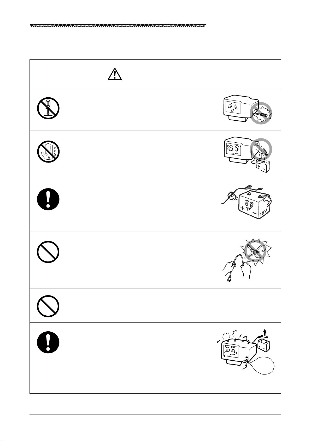
WARNING
Do not disassemble or modify the equipment. Failure
to observe the instruction can cause a fire, electric
shock, or equipment failure.
Do not connect or disconnect the power supply cable
with a wet hand. Otherwise, you may suffer from an
electric shock.
Operate the equipment only at the power supply
voltage of 12 or 24 VDC. Failure to observe this
instruction can cause a fire, electric shock, or
equipment failure.
Do not scratch, damage, or modify the power supply
and antenna cable. It may be damaged to cause a fire
or electric shock if it is loaded with a heavy item, heated,
pulled, or excessively bent.
Do not operate the equipment while steering the
vessel. It can cause accidents.
Immediately turn the power off and disconnect the
power supply cable if the equipment is generating any
smoke or odor, or found overheated. Then, promptly
inform our local service agent of the symptom to have
it corrected. Prolonged equipment operation under
such a condition can cause a fire or electric shock.
3
JLR-7700 MK2GPS Navigator
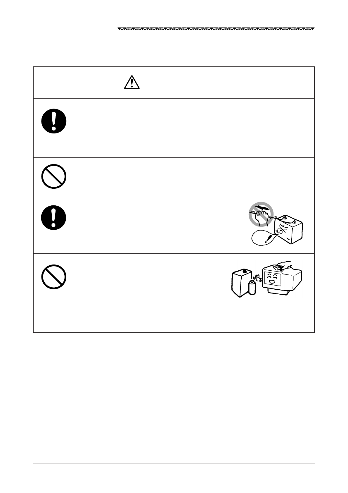
This equipment is not designed to automatically make
judgments on the position data. The navigation
information including the position data needs to be
judged by the user himself.
Do not allow the equipment to fall or immerse in water.
The equipment can be damaged.
CAUTION
When removing the power and antenna cord, be sure
to remove the cord terminal correctly. If the cord is
pulled, the cord may be damaged resulting in a fire or
an electrical shock.
When cleaning the surface, do not use any organic solvent such as thinner or benzine.
Otherwise, the painting on the surface may be
damaged.
For cleaning the surface, remove the dust and
refuse and wipe with clean dry cloth.
No
Thinner
Benzine
4
JLR-7700 MK2GPS Navigator
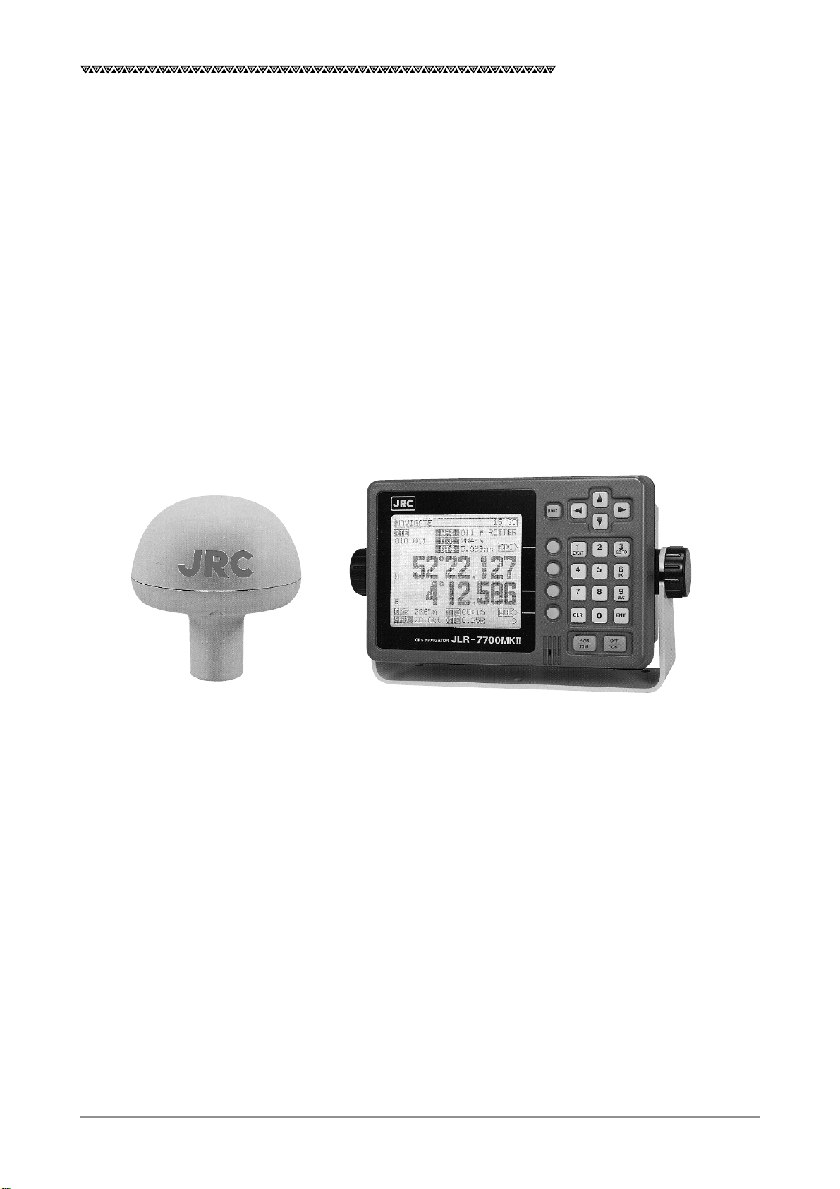
Appearance of the Equipment
DGPS Receiver Navigator
5

JLR-7700 MK2GPS Navigator
Table of Contents
Foreword ............................................................................................................................. 1
Before Commencing the Equipment Operation................................................................... 2
Precautions Upon Equipment Operation............................................................................. 3
Appearance of the Equipment............................................................................................. 5
Key Terms ............................................................................................................................9
1. Equipment Overview ................................................................................................... 11
1.1 Functions .......................................................................................................................................11
1.2 Features .........................................................................................................................................12
1.3 Configuration ................................................................................................................................. 13
1.4 Construction...................................................................................................................................14
1.5 General System Diagram............................................................................................................... 17
2. Unit Descriptions and Functions ................................................................................. 18
2.1 Operation Panel of the Navigator ...................................................................................................18
2.2 Rear Panel of the Navigator........................................................................................................... 20
2.3 DGPS Receiver.............................................................................................................................. 21
3. Installation ................................................................................................................... 22
3.1 Installation of the DGPS Receiver ................................................................................................. 22
3.1.1 Selecting the Position for Installation .......................................................................................22
3.1.2 Installation Procedure of the DGPS Receiver..........................................................................23
3.1.3 Installation of the DGPS Receiver on the Mast .......................................................................24
3.2 Installation of the Navigator ...........................................................................................................25
3.2.1 Selection of the Installation Location .......................................................................................25
3.2.2 Installation of the Navigator .....................................................................................................26
3.3 Installation of the Junction Box ......................................................................................................28
3.3.1 How to Mount the Junction Box on the Mast ...........................................................................28
3.3.2 Pole Mounting Kit .....................................................................................................................29
3.3.3 How to Mount the Junction Box on a Flat Surface ...................................................................29
3.4 Connection of the Navigator .......................................................................................................... 30
3.4.1 Connection of the Power Supply Cable ...................................................................................30
3.4.2 Connection of the Grounding Line ...........................................................................................30
3.4.3 Connection of the DGPS Receiver ..........................................................................................31
3.4.4 Data Output .............................................................................................................................32
3.4.5 Relay Output ............................................................................................................................ 33
3.4.6 Connection of the Junction Box ...............................................................................................34
3.4.7 Connection of the Waterproof Connectors (2, 6, or 7-pin Connector) .................................... 35
3.4.8 Connection Cable (Optional Unit) ............................................................................................35
3.5 Measures for the Electromagnetic Interference .............................................................................36
3.5.1 Checks before the Connection ................................................................................................36
3.5.2 Checks before the Navigation ..................................................................................................36
3.6 How to Connect the NQA-4251 Buffer Unit (Optional Unit) ...........................................................37
3.7 Connection of the NBA-3581A AC Power Supply Unit (Optional Unit) ..........................................37
3.8 Connection of the NKG-84 Printer (Optional Unit) ......................................................................... 38
6

JLR-7700 MK2GPS Navigator
4. Operation Method ....................................................................................................... 39
4.1 Basic Operations ........................................................................................................................... 39
4.1.1 Turning the Power ON and OFF ..............................................................................................39
4.1.2 Selection of the Language .......................................................................................................39
4.1.3 Contrast Adjustment ................................................................................................................39
4.1.4 Backlight Adjustment ...............................................................................................................40
4.1.5 Return to the SELECT MODE Screen..................................................................................... 40
4.2 Screens..........................................................................................................................................40
4.2.1 Display and Operation List for the NWZ-4570B Navigator ...................................................... 41
4.3 How to use the Navigation Information Screens ............................................................................42
4.3.1 NAVIGATE Screen ...................................................................................................................42
4.3.1.1 Setting a Destination ......................................................................................................... 43
4.3.1.2 To Change the Leg (Manual Leg Change) ........................................................................45
4.3.1.3 To Skip (Omit) a Destination ..............................................................................................45
4.3.1.4 Canceling the Route ..........................................................................................................46
4.3.1.5 Storing the Current Position (Event) ..................................................................................46
4.3.2 COURSE DEVIATION IND. Screen ......................................................................................... 47
4.3.2.1 Switching the CDI Meter Scale ..........................................................................................47
4.3.2.2 Switching the Display on the Two Bottom Lines ................................................................ 47
4.3.3 NAVIGATE AUX Screen...........................................................................................................49
4.3.3.1 Magnetic Compass Correction ..........................................................................................49
4.3.3.2 Setting the Display Unit .....................................................................................................50
4.3.3.3 Selection of the Data Output Format .................................................................................50
4.4 PLOT Screen (Tracked Line Screen) .............................................................................................52
4.4.1 PLOT Screen ...........................................................................................................................52
4.4.1.1 Setting the Horizontal Scale Range...................................................................................52
4.4.1.2 Setting the Plot Interval ..................................................................................................... 52
4.4.1.3 Erasing the Tracked Line ................................................................................................... 53
4.4.1.4 Setting a Destination ......................................................................................................... 53
4.4.1.5 To Store the Current Position.............................................................................................53
4.4.1.6 Turning ON and OFF the Display for the Two Bottom Lines .............................................. 53
4.4.1.7 To Display the Current Position at the Center of the Screen .............................................53
4.4.2 PLOT AUX Screen ...................................................................................................................54
4.4.2.1 Setting the Geodetic System .............................................................................................54
4.4.2.2 Setting the DGPS BEACON ..............................................................................................55
4.5 Registration the Waypoint ..............................................................................................................56
4.5.1 WAYPOINT Screen ..................................................................................................................56
4.5.2 WAYPOINT LIST Screen ......................................................................................................... 58
4.5.2.1 Copying the Waypoint Data ............................................................................................... 58
4.5.2.2 Erasing the Waypoint Data ................................................................................................58
4.5.3 ROUTE SEQUENCE Screen...................................................................................................59
4.5.3.1 Setting the Route Plan.......................................................................................................59
4.5.3.2 Canceling the Route Plan ..................................................................................................59
4.5.3.3 Setting the Arrival Alarm Range ........................................................................................60
4.5.3.4 Switching between the Automatic and Manual Leg Change .............................................60
4.5.3.5 Switching between Great-circle and Rhumb-line............................................................... 61
7

JLR-7700 MK2GPS Navigator
4.5.4 Setting the Navigation Alarms .................................................................................................62
4.5.4.1 Setting the Arrival Alarm Range ........................................................................................62
4.5.4.2 Setting the Off-Course Alarm Range .................................................................................62
4.5.4.3 Setting the Anchor Alarm Range .......................................................................................63
4.5.4.4 Setting the Boundary Alarm Range ...................................................................................64
4.6 SAT STATUS Screen ......................................................................................................................65
4.6.1 INITIAL SETTING Screen........................................................................................................65
4.6.1.1 Setting the Initial Data ....................................................................................................... 65
4.6.1.2 Setting the Loran Station ...................................................................................................66
4.6.1.3 Search the Sky ..................................................................................................................66
4.6.1.4 Master Reset .....................................................................................................................66
4.6.2 GPS AUX Screen ....................................................................................................................67
4.6.2.1 Setting the Averaging for Position Display .........................................................................67
4.6.2.2 Setting the HDOP Level ..................................................................................................... 68
4.6.2.3 Setting the Antenna Mode .................................................................................................69
4.6.2.4 Setting the RAIM Accuracy Level ......................................................................................70
4.6.3 Weather Information ................................................................................................................ 70
4.7 Special Functions .......................................................................................................................... 71
4.7.1 Loran Time Difference Display .................................................................................................71
4.7.1.1 Setting the Loran A Station................................................................................................71
4.7.1.2 Setting the Loran C Station ............................................................................................... 72
5. Maintenance and Inspection ....................................................................................... 74
6. Measures for the Operating Environment ................................................................... 75
7. After-the-sale Services ................................................................................................ 76
8. Disposal ......................................................................................................................77
8.1 Disposal of the Equipment ............................................................................................................. 77
8.2 Disposal of the used Battery .......................................................................................................... 77
9. Specifications .............................................................................................................. 79
Attachments
Attachment 1 Optional Units .............................................................................................................82
Attachment 2-A List of Messages ........................................................................................................86
Attachment 2-B List of Geodetic Systems ............................................................................................88
Attachment 2-C NMEA0183 Output Sentence Data Format ................................................................90
Attachment 2-D Table of Waypoints....................................................................................................104
8

JLR-7700 MK2GPS Navigator
Key Terms
Term Description
GPS satellites The term is an acronym that represents the Global Positioning System,
which is managed by the US Department of Defense to support its navigation aid system.
DGPS The term is an acronym that represents the Differential Global Positioning
System, which is a system to improve the position fixing accuracy by receiving the correction data with a beacon receiver for a given GPS satellite, which is transmitted by the beacon station with a known position.
Position fixing The term means to obtain the current position of your vessel with the
GPS or DGPS receiver.
2D (Two-dimensional position fixing) The term 2D means the position fixing with data obtained from the satel-
lites and antenna height information.
3D (Three-dimensional position fixing) The term 3D means the position fixing with four or more satellites infor-
mation only.
HDOP The term is an acronym that represents the Horizontal Dilution of Preci-
sion, which reflects the position fixing accuracy. The accuracy increases
as the value decreases.
The value increases when the satellites are gathered close to each other,
and it decreases when the satellites are spattered, which in turn means
increased accuracy.
Loran time difference display This is a method to display the current position using the time difference.
(This method is recommended for the experts who have good knowledge on the Loran navigation method.)
TD The term is an acronym that represents the Time Difference, which is equal
to the time difference between the master and secondary Loran signals.
Route plan This is the plan that consists of the multiple waypoints registered in the
order of navigation.
CDI The term is an acronym that represents the Course Deviation Indicator,
which includes information on the deviation from a given planned course
and direction to be steered.
Arrival alarm The alarm notifies that your vessel has arrived at the preset distance
from a given destination.
9

JLR-7700 MK2GPS Navigator
Anchor alarm The alarm notifies that your vessel has drifted away from the destination
by the preset distance.
Off-course alarm The alarm notifies that your vessel has been deviated from the planned
course by the preset distance.
Boundary alarm The alarm notifies that your vessel has crossed the preset boundary
line.
Automatic sequencing mode The function automatically switches the next destination after your ves-
sel has entered the preset arrival alarm range during the navigation according to the route plan.
Manual sequencing mode The function allows the operator to manually change to the next leg by
operating the keys provided on the equipment during the navigation based
on the route plan.
Default values The values represent the factory settings.
NMEA 0183 This is a standard specified by an international organization called the
National Marine Electrical Association (NMEA) to specify the requirements for the communications among various navigator.
Master reset The function clears all the settings on the equipment and the NNN-4321
DGPS receiver connected to it. Note that all the settings will be cleared
if the function is performed.
Initialization A maximum duration of 2 minutes is required for position fixing if the
equipment is to be operated for the first time after the installation or the
master reset function has been performed. The initialization can reduce
the time for position fixing by manually entering the estimated position,
time, and antenna height.
Course A direction obtained by connecting the positions tracked by the vessel,
which is mainly the direction displayed by the GPS.
Bearing An angle formed between the local meridian and the orientation of the
bow during the navigation, which is mainly displayed on the gyro or
magnetic compass.
RAIM Acronym of "Receiver Autonomous Integrity Monitoring." This denotes
the function of judging by GPS receiver itself whether the positioning
accuracy is within the required accuracy.
WER Acronym of "Word Error Rate." This indicates the receiving condition of
the data transmitted from DGPS base stations. The value decreases
when the condition is better.
10
JLR-7700 MK2 GPS Navigator
1. Equipment Overview
1.1 Functions
The JLR-7700 MK2 is a DGPS navigation equipment configured by connecting the NNN-4331 DGPS re-
ceiver to the NWZ-4570B navigator. The DGPS navigation equipment measures the vessel position all the time
with very high accuracy using the data provided by the GPS satellites under any geographical or weather
conditions and its measurement accuracy can be further enhanced by receiving compensation data from the
DGPS beacon station. The equipment displays the following navigation screens and GPS statuses based on
data retrieved by the DGPS receiver.
(1) Navigation screens
These screens display the navigation information to go to the destinations that have been preset to the
equipment.
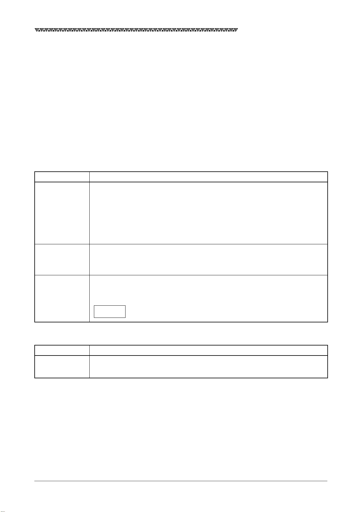
Screen name Remarks
NAVIGATE screen The current position is displayed with the latitude and longitude. Information required
for navigation, such as the bearing, distance, course, and speed to the destination,
can also be displayed. Other navigation information, such as the deviation from the
preset navigation course, direction to steer, and estimated time of arrival to the
destination can be displayed. In addition, the Loran time difference can also be
displayed as well.
COURSE The course deviation can be graphically shown on the display by selecting the CDI on
DEVIATION IND. the NAVIGATE screen. In addition, the direction to steer will also be displayed.
screen
PLOT screen The planned navigation course and actual navigation tracked by your vessel can be
graphically displayed. The waypoints can be displayed with symbols and alphabets.
The current position can be registered as the waypoint by simply pressing the
1
key.
EVENT
(2) Satellte status screens
Screen name Remarks
SAT STATUS Which provides the operator with the GPS information (the satellite number, elevation
screen angle, azimuth angle, and signal level).
11

JLR-7700 MK2 GPS Navigator
1.2 Features
・ The equipment can be operated with ease by simply selecting the menu displayed on the screen.
・ A large LCD ensures simultaneous display of various navigation information required, which in turn
eliminates the necessity for frequently switching the display.
・ NNN-4331 DGPS receiver for differential position fixing offers a higher accuracy position.
・ A maximum of 499 waypoints can be stored.
・ Each waypoint can be displayed with alphanumeric.
・ Two data outputs are available and either one of the NMEA 0183 versions 1.5, 2.1, or 2.3 (IEC61162-1) can
be selected. Note that one of the two outputs is of RS422 level.
・ The position information obtained by the GPS can be displayed in the Loran time difference as well.
・ The graphically displayed COURSE DEVIATION IND. screen enables the operator to determine the steering
direction by simply taking a look at it, which in turn ensures safety and economical navigation. In addition,
the symbols attached to the respective waypoints can be displayed on the PLOT screen besides the actual
navigation tracked by your vessel.
・ The equipment can display information either in Japanese or English.
・ Local weather and sea conditions in coastal sea areas of Japan can be displayed.
12

JLR-7700 MK2 GPS Navigator
1.3 Configuration
The equipment consists of the units shown in the table below. Immediately inform our local sales office or
your distributor if any one of them is found missing.
Unit Model Quantity Remarks
Navigator NWZ-4570B 1
Bracket CFQ-8919 1 5m with connector (For navigator)
Power supply cable CFQ-3598B 1 1.8m with connector (For navigator)
DGPS receiver NNN-4331 1 With 15m cable
Screw mount MTV302007 1 (For DGPS receiver)
Fitting belt MPBP02520 1 set Include 2 belts (For DGPS receiver)
Connector 6-282-7SG-321 1 (For data output)
Copper plate 1 25W×2000×0.3t (For navigator)
Spare parts 1 set 2A fuse
Suppression ferrite E04SR200935A or equivalent 1 See the item 3.4.3 "Connection of
the DGPS Receiver" for the
mounting method
Mounting screws MPTG02342 1 set
Instruction manual 7ZPNA4032 1
Three self-tapping screws with washers
In addition, the following items are available as the optional units.
Unit Model Uses
Junction box NQE-7700A
Pole mounting kit MPBP30608
Output buffer NQA-4251 The buffer can divide the output from the
navigator to twelve other external equipment
connected in parallel.
AC power supply unit NBA-3581A The rectifier converts the AC power (100 or 200
VAC) into the rated power supply voltage of 24
VDC for NWZ-4570B.
Further, the 24 VDC power as supplied from the
battery may be connected to the navigator to
backup the AC power supply.
Printer NKG-84 Various information displayed on the navigator
information, SAT status and so on can be
printed out by connecting the DATA OUT
connector provided on the rear panel of the
navigator to the printer using the optional data
cable (CFQ-8921).
Data cable CFQ-8921 The data cable can used when it is necessary to
output data from the DATA OUT connector
provided on the rear panel of the navigator.
Extension cable 250V-MPYCYS-5 or The cable is used to extend the cable for the
250V-MPYCYS-7 DGPS receiver, which is recommended as the
standard extension cable.
13
JLR-7700 MK2 GPS Navigator
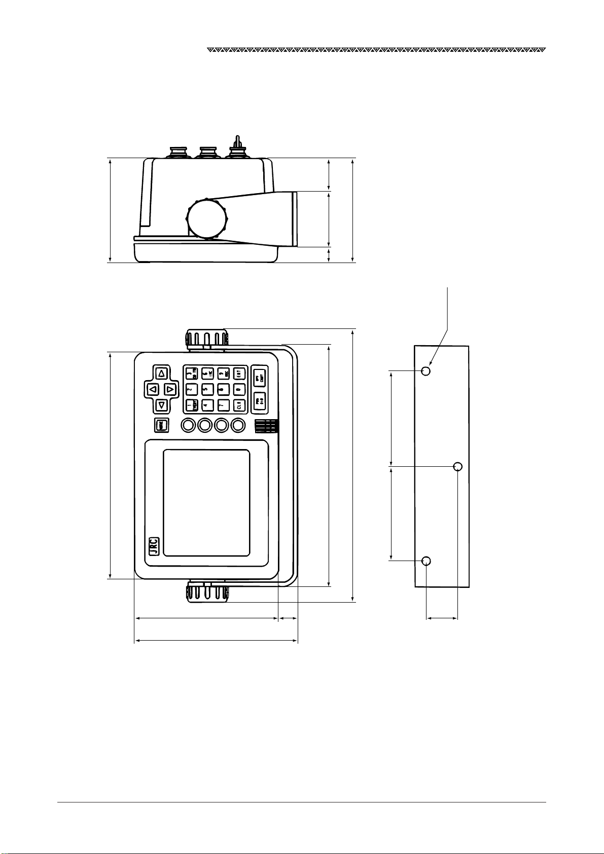
1.4 Construction
(1) Outline drawing of NWZ-4570B navigator
2915
94212
50
224
94
252
90
REAR
3-φ6.5
FRONT
90
1341630
150
Unit : mm
Weight : less than 1.8Kg
14

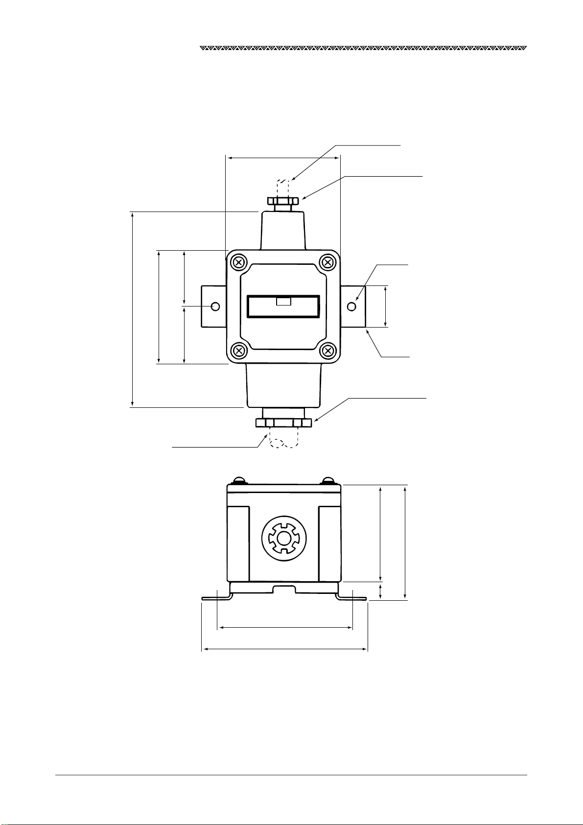
(2) Outline drawing of NNN-4331 DGPS receiver
φ198
φ150
JLR-7700 MK2 GPS Navigator
φ126
φ6
135
42
φ40
Mounting screw:
1INCH 14 UNS-2B
Unit : mm
Weight : less than 1.7Kg
15
JLR-7700 MK2 GPS Navigator
(3) Outline drawing of NQE-7700A junction box
41.5
DGPS cable
CFQ-8919
85
Gland φ15
2-φ7
(139)
83
41.5
250V-MPYCYS-7
JRC
NQE-7700A
30
SUS
Gland φ25
70
82
16
12
100
120
Unit : mm
Weight : less than 0.7Kg
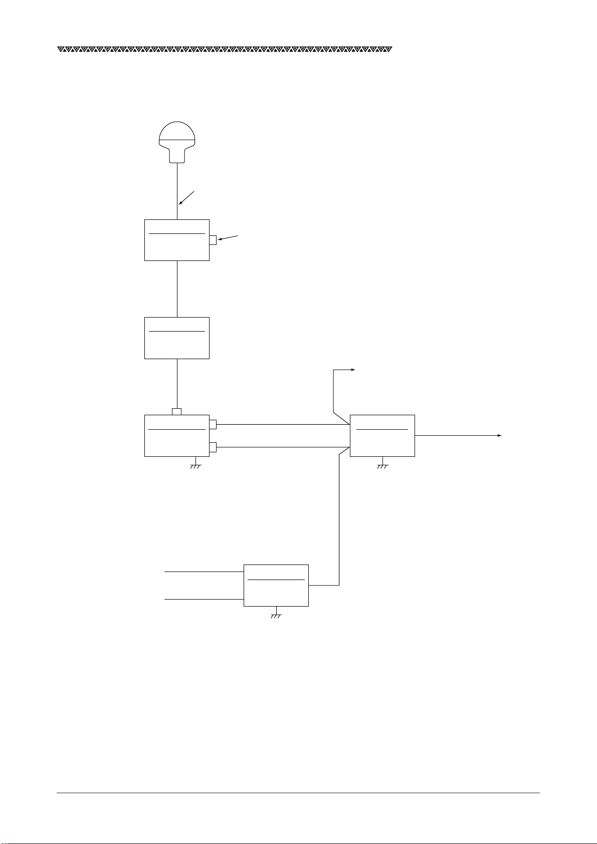
1.5 General System Diagram
NNN-4331
DGPS receiver
Attached cable (length:15m)
(Cut the cable to the required length)
JLR-7700 MK2 GPS Navigator
*NQE-7700A
Junction box
*250V-MPYCYS-5 or 250V-MPYCYS-7
(Max. 50m)
*NQE-7700A
Junction box
DGPS cable
CFQ-8919 5m
NWZ-4570B
Navigator
*With pole mounting kit
MPBP30608
Data cable
CFQ-8921 3m
*
DC power supply cable
CFQ-3598B 1.8m
Log pulse or external buzzer
*NQA-4251
Buffer unit
Data out 1 to 12
AC100-115/220-240V
1φ50/60Hz
DC24V
*NBA-3581A
AC power
supply unit
*250V-DPYC-1.25
*Option
17
JLR-7700 MK2 GPS Navigator
2. Unit Descriptions and Functions
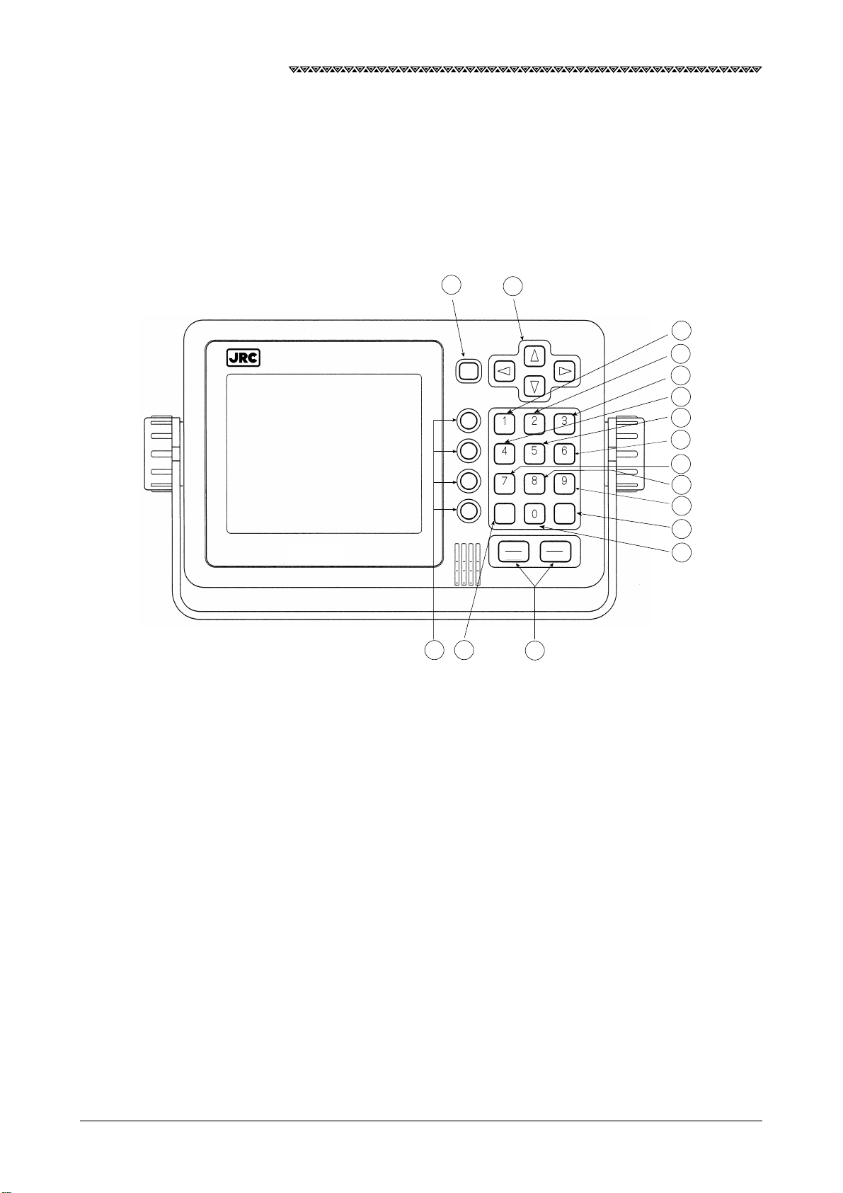
2.1 Operation Panel of the Navigator
The following figure shows the keys provided on the operation panel of the navigator and the functions
thereof.
15
11
13
MODE
14
EVENT
CLR ENT
OFF
PWR
CONT
DIM
16
GOTO
1
2
3
4
5
6
INC
DEC
7
8
9
12
10
Fig. 2-1 Operation Panel of the Navigator
18
No. Description Function
JLR-7700 MK2 GPS Navigator
1
2
3
4
5
6
7
8
9
10
11
1
EVENT
2
3
GOTO
4
5
6
INC
7
8
9
DEC
0
MODE
To enter the numerical value “1” or memorize the event (for the waypoint
numbers 400 to 499).
To enter the numerical value “2”.
To enter the numerical value “3” or to set the one destination.
To enter the numerical value “4”.
To enter the numerical value “5”.
To enter the numerical value “6”, to magnify the plot scale, or to adjust the
contrast.
To enter the numerical value “7”.
To enter the numerical value “8”.
To enter the numerical value “9”, to reduce the plot scale, or to adjust the
contrast.
To enter the numerical value “0”.
To the selection screen.
12
13
14
15
16
PWR
DIM
ENT
CLR
OFF
CONT
To execute a given data input.
To erase a wrong input data or to turn off the alarm sound.
To move the cursor or waypoints on the list.
Selection on the menu.
To turn on and off the power, to adjust the backlight, or to start or finish the
contrast adjustment.
19
JLR-7700 MK2 GPS Navigator
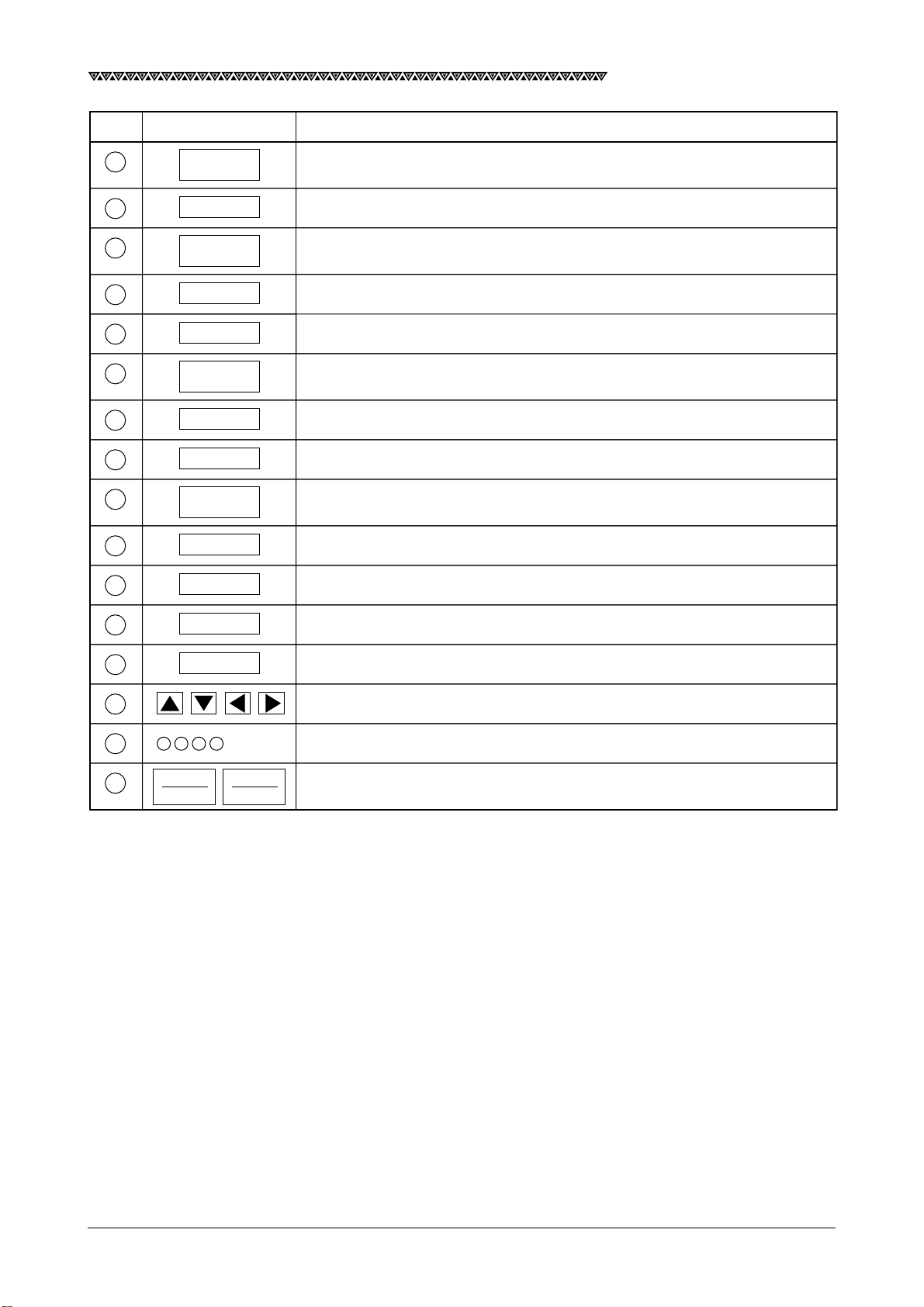
2.2 Rear Panel of the Navigator
17
18
19
20
Fig. 2-2 Rear Panel of the Navigator
No. Description Function
DATA OUT connector This connector outputs various data (DATA 1 and DATA 2) for the plotter,
17
auto pilot, printer, remote display and so on, in addition to the external
buzzer or log pulse.
18
GPS/DGPS connector This connector connects the NNN-4331 DGPS receiver.
12/24 VDC connector This connector connects the CFQ-3598B power supply cable included in
19
the equipment.
Terminal E This connector needs to be connected to the earth of the vessel frame.
20
Use the attached copper tape (25W×2,000×0.3t) to connect it.
20
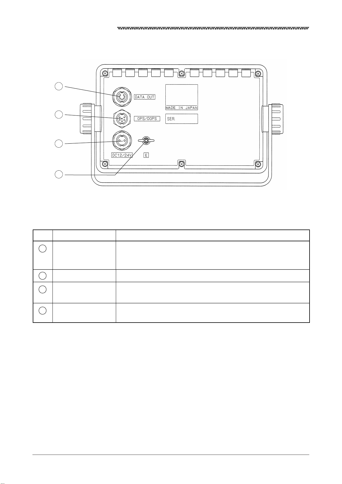
2.3 DGPS Receiver
① Receiver
JLR-7700 MK2 GPS Navigator
② Cable
③ Aluminum base
④ Connector
No. Name Function
Receiver To provide DGPS position fixing by receiving GPS signals form a maximum of
1
twelve satellites as well as DGPS correction data from ground beacon stations.
Cable To supply DC power for the antenna and input/output a data to a navigation
2
equipment 6 wires cable.
Aluminum base To mount on a navigation antenna mount unit or on an extension mast
3
conforming to 1"×14 NPT standards.
Connector To connect with the navigator 6-pin connector.
4
21
JLR-7700 MK2 GPS Navigator
3. Installation
3.1 Installation of the DGPS Receiver
3.1.1 Selecting the Position for Installation
CAUTION
When connecting the cable attached to the equipment, do not bend it to an
acute angle, twist it, or impart excessive force because this sometimes causes
cracks or damage to the coating.
Do not install the receiver where there is excessive vibration.
Vibration may cause receiver failure.
Install the receiver where there is no obstacle, in order to ensure that GPS
signals can be directly received from satellites without interference or reflection
of signals from surrounding objects.
Whenever possible, select a place having the following characteristics.
1. An open space which allows uniform reception of satellite signals
2. Far away from any of high power transmission antennas
3. Outside radar beam range
4. Away from the inmarsat antenna by not less than 5 meters and below the level
of its antenna
5. Away from the antenna of a direction finder by not less than 5 meters
6. Away from the magnet compass by not less than 1 meter
If it is difficult to find an ideal site, select a place temporarily and install the equipment.
Conduct a test to make sure that the proper performance can be obtained and then fix
the equipment in position. If it is installed at an improper place, reception may become
intermittent, resulting in shorter position fixing time and poorer position accuracy.
22
JLR-7700 MK2 GPS Navigator
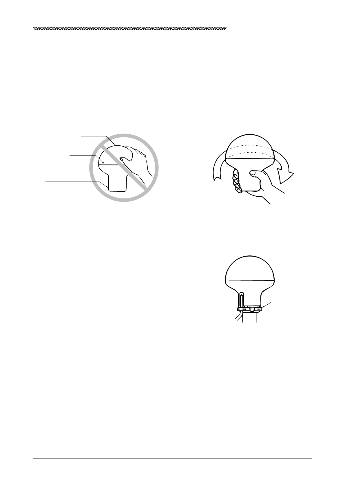
3.1.2 Installation Procedure of the DGPS Receiver
The aluminum bottom of the DGPS Receiver is designed so that it can be installed on screws, mounting
conforming to 1”×14. The bottom of the receiver is provided with a slot to allow the receiver cable to be pulled
out to the side.
① Pull out the receiver cable from aluminum base.
② Screw screws, mounting into the aluminum base. As shown below grip the base. Don’t grip joint between
cover and aluminum base.
Cover
Joint
Aluminum base
Don't grip joint Grip the aluminum base
Installation of the DGPS receiver
③ When the receiver cable is pulled out through the slot,
securer it in position to protect it against damage due to
vibration.
④ Connect extension cable with the DGPS receiver. Those
connectors should be sealed with selfbonding tape due to
water proofing.
Tie wrap
Appearance
23
JLR-7700 MK2 GPS Navigator
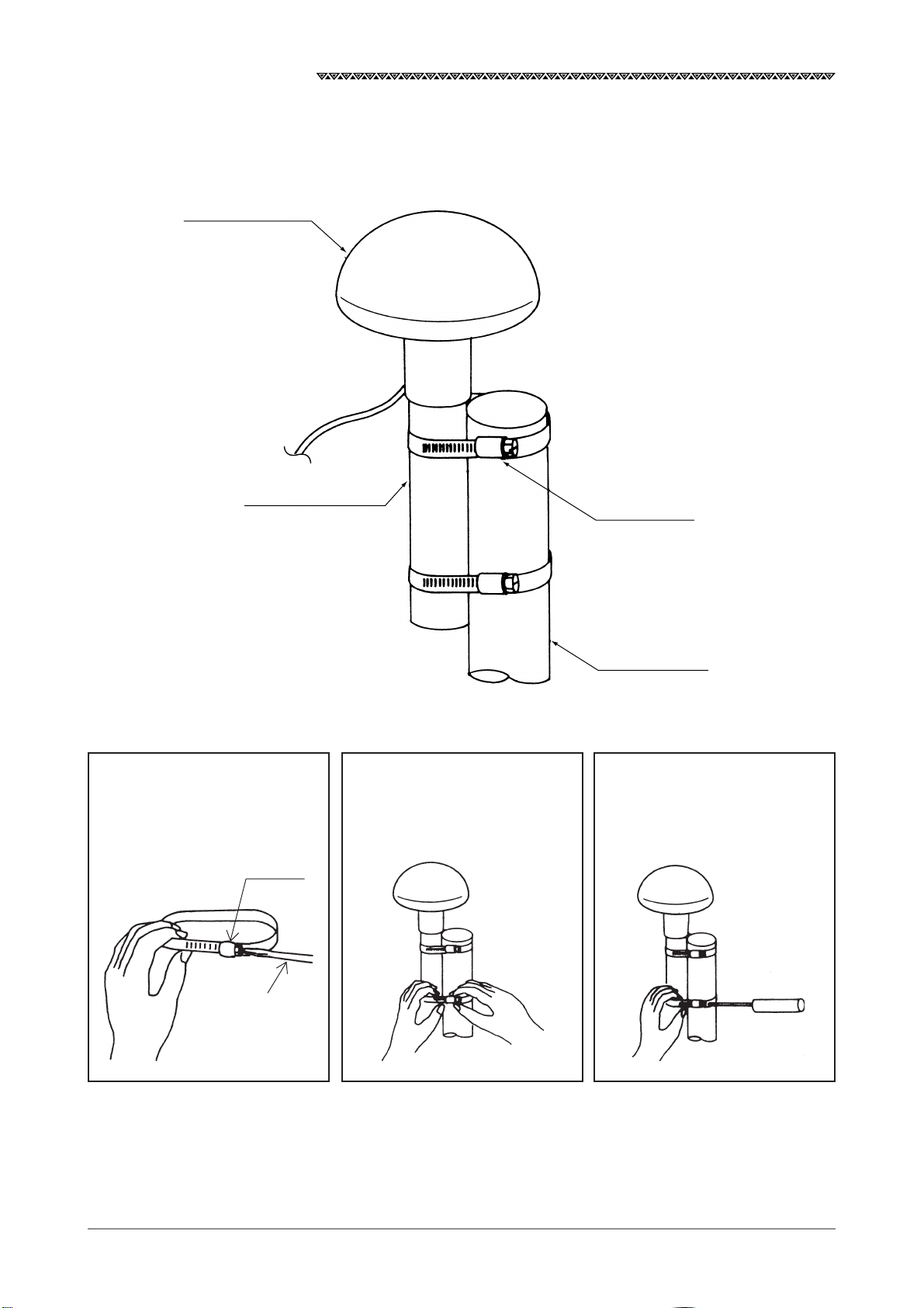
3.1.3 Installation of the DGPS Receiver on the Mast
The following figure shows how to install the receiver on the mast.
DGPS receiver
NNN-4331
Screws, mounting
MTV302007
1. Loosen the fitting belt screw
with a screwdriver to remove
the clamp.
Clamp
2. Coil the fitting belt around mast
as shown below.
Fitting belt
MPBP02520
Mast
(φ26〜φ90)
3. Tighten the clamp screw with
the screwdriver.
24
Minus screwdriver
How to Install the Receiver on the Mast

JLR-7700 MK2 GPS Navigator
3.2 Installation of the Navigator
CAUTION
Keep the equipment away from the magnetic compass by a minimum of one
meter when installing it. Failure to observe this instruction can cause
malfunctioning of the compass.
3.2.1 Selection of the Installation Location
Pay sufficient attention to the following two points when installing the equipment.
・ Select a location that can provide ease in operating the equipment and viewing information displayed on the
screen.
・ Observe the following instructions.
Do not install the equipment at a location subject to the
direct sunlight or nearby the heat source (50℃ or higher).
Do not operate the equipment at a location that is
subject to water droplets, rainwater, or condensation.
Keep the equipment away from the magnetic sources such
as the magnetic compass, speaker, or motor since they
can damage the electronic circuit in the equipment.
Keep the equipment away from the radio set, radar, TV
set, fluorescent lamp, antenna, etc. to avoid possible
radio interference.
25

JLR-7700 MK2 GPS Navigator
3.2.2 Installation of the Navigator
WARNING
Secure the bracket with the screws provided with the equipment. Failure to
observe the instruction can cause injury or property damage since the
equipment is likely to drop.
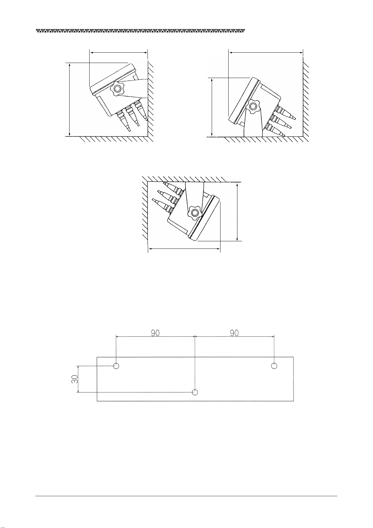
Firstly, secure a space for the mount according to Fig. 3-1. Then, secure the mount by following the procedures
shown below.
(1) Determine the location to install the equipment. Mark the three mounting screw positions with a pencil or
equivalent. See the Fig. 3-2 for the mounting screw hole size.
(2) Secure the bracket at the installation location using the three self-tapping screws.
(3) Mount the equipment on the bracket and confirm that it is securely mounted.
(4) Adjust the orientation of the equipment to an optimum position.
26
JLR-7700 MK2 GPS Navigator
200
160
200
160
160
200
Fig. 3-1 Installation Orientation and Spatial Requirements
Rear
Front
Unit : mm
Unit : mm
Fig. 3-2 Bracket Mounting Dimensions
27
JLR-7700 MK2 GPS Navigator
3.3 Installation of the Junction Box
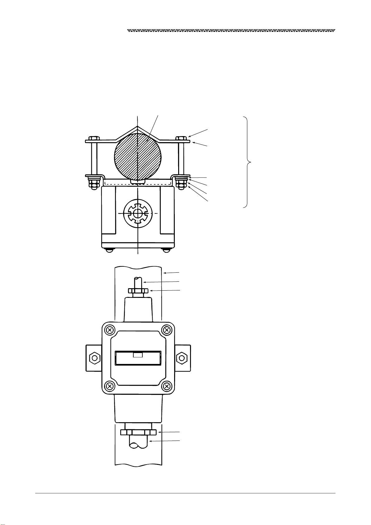
3.3.1 How to Mount the Junction Box on the Mast
Securely mount the junction box on the mast using the pole mounting kit (See the item 3.2.2 “Pole Mounting
Kit” for details.).
Pole (φ26〜φ53)
BOLT SUS
M6×50
SUS
Pole mounting kit
(MPBP30608)
W6 SUS
SW6 SUS
N6 SUS
LN6 SUS
JRC
NQE-7700A
* SUS : Stainless steel
Pole (φ26〜φ53)
For DGPS receiver
Gland φ15
28
Gland φ25
250V-MPYCYS-7

3.3.2 Pole Mounting Kit
The following figure shows the items included in the pole mounting kit.
130
JLR-7700 MK2 GPS Navigator
165
Pole mounting kit
MPBP30608
Unit : mm
3.3.3 How to Mount the Junction Box on a Flat Surface
Securely mount the junction box on a given flat surface using the self-tapping screws and flat washers.
NQE-7700A
Junction box
Self-tapping screws φ5
Flat washers
Memo
The self tapping screws and flat washers in the figure above are not accessories of this equipment.
29

JLR-7700 MK2 GPS Navigator
1
2
3.4 Connection of the Navigator
3.4.1 Connection of the Power Supply Cable
A 1.8m long DC power supply cable is included in the equipment, which needs to be securely inserted all the
way into the 12/24 VDC connector provided on the rear panel of the navigator.
Pin No. Remarks
1 DC −
1.8m long cable
2A fuse
2 DC +
Black (-)
Red (+)
Connect the red cable to the plus terminal of the battery or power distribution panel and the black cable to the
minus terminal.
The equipment needs to be connected to the DC power supply source having the voltage range of 10 to 35
VDC. The power consumption by the equipment is 10 W or less with the GPS or DGPS receiver connected to
it. Use an AWG #17 cable or greater if the attached CFQ-3598B power supply cable (1.8m long) needs to be
extended.
3.4.2 Connection of the Grounding Line
The navigator needs to be grounded to protect it from the static electricity and to avoid possible noise
generation. Connect the terminal “E” provided on the rear panel of the navigator to the nearest vessel frame
with the copper plate (25Wx2,000x0.3t) included in the equipment.
Power supply cable
CFQ-3598B
12/24 VDC connector
30

JLR-7700 MK2 GPS Navigator
3.4.3 Connection of the DGPS Receiver
See the description under the item 2.2 “ Rear Panel of the Navigator” for the connectors provided on the rear
panel of the navigator.
CAUTION
Keep the excessive DGPS connection cable away from the navigator by a
minimum of 30 cm after connecting it. Failure to observe the instruction can
cause interference to other radio equipment.
The navigator supplies the 12 VDC power to the DGPS receiver. The DGPS receiver is activated when the
equipment is turned the power on to receive information from the satellites and transmit it to the navigator.
① Securely insert the CFQ-8919 DGPS cable plug into the “GPS/DGPS” connector provided on the rear panel
of the navigator.
Pin No. Remarks
1
6
2
3
5
4
1 12 VDC output
2 Ground
3 Data common (Ground)
4 GPS data input
5 GPS setting data output
6 Open
GPS/DGPS connector
② Then, mount the suppression ferrite included in the package on the cable at a position closest to the GPS/
DGPS connector to eliminate any unwanted noise.
Suppression ferrite
(E04SR200935A or equivalent)
Cable
31

JLR-7700 MK2 GPS Navigator
3.4.4 Data Output
The “DATA OUT” connector provided on the rear panel of the navigator can output data for the plotter, auto-
matic pilot, printer, remote display unit, fishfinder, radar and so on.
The format of data to be output can be selected from the following four types. Two each peripheral units can
be connected to the DATA 1 or DAT 2 output.
Output format available Number of external equipment
for data 1 and 2 that can be connected
NMEA0180 2 units each
NMEA0183Ver1.5 2 units each
NMEA0183Ver2.1 2 units each
NMEA0183Ver2.3 (IEC61162-1) 2 units each
JRC format 2 units each
NMEA0183Ver2.3/SEC 2 units each
CAUTION
If select “NMEA0183 output per second” at DATA1 (or DATA2), the output of
DATA2 (or DATA1) is fixed to “NMEA0183 output per second” automatically,
and other data format can not be selected.
See the item 4.3.3.3 “Selection of the Data Output Format” to switch the data format.
Pin No. Remarks
1
2
3
DATA OUT connector
7
6
5
4
1 Data 1 output (TTL level)
2 Data 1 common (GND) (TTL level)
3 Data 2 output ( + ) (RS-422 level)
4 Data 2 output ( − ) (RS-422 level)
5 NC
6 Relay output (Log pulse), + output
7 Relay output (Log pulse), − output
32

JLR-7700 MK2 GPS Navigator
3.4.5 Relay Output
The relay circuit of the navigator can output either the external buzzer or log pulse.
The relay circuit outputs the signals shown in the table below via the pin numbers 6 and 7 of the DATA OUT
connector described under the item 3.4.4 “Data Output”.
Note that the maximum loading capacity of the connector pins is 200 mA at 24 VDC.
Output Screen display Description
External buzzer EXT BUZZER An external buzzer can activate any sound alarms described in
the Attachment 2-A. Pressing the CLR key can stop the alarm
sound in the same manner as that with the navigator.
Log pulse LOG PULSE The log pulse is calculated and output at a rate of 200 pulses per
nm based on the vessel speed, which is mainly fed to a radar or
equivalent.
Press the MODE PLOT and AUX keys.
Then, press the BUZZER/LOG to select a desired data output (either the external buzzer or the log pulse).
The screen returns to the PLOT screen when the ENT key is pressed.
6
7
DATA OUT connector
Relay circuit
33

JLR-7700 MK2 GPS Navigator
3.4.6 Connection of the Junction Box
Connect the respective cables (cable from the DGPS receiver and extension cable) to the terminals provided
in the junction box as shown in the following figure.
Cable from the DGPS receiver
Cable from the Terminal in the
DGPS receiver junction box
Cable length:
55±5mm
Cable length:
45±5mm
Red 1
Black 2
White 3
Green 4
Yellow 5
Brown 6
Shield cable 3
Terminal plate
Extension cable
CAUTION
34
The rubber gasket is suitable for the cable of size φ10 to φ20.

JLR-7700 MK2 GPS Navigator
3.4.7 Connection of the Waterproof Connectors (2, 6, or 7-pin Connector)
(1) Strip the cable end as shown in the figure below.
(2) Put the respective parts through the cable as shown in the assembly drawing.
(3) Solder the cable ends to the socket contacts, and cap the socket contact with the rubber grommet by
allowing it to slide on the contact body surface so that it will be securely covered.
(4) Put the O-ring through the connector body all the way to the end.
(5) Secure the back shell on the connector body.
(Align the notch provided on the back shell with the tab on the body and press them each other, then, turn
them to secure. It is recommended to insert the connector body into the navigator connector if the above
approach is found difficult.)
Unit : mm
Stripping Dimensions on the Cable End
Rubber grommet
Back shell
3.4.8 Connection Cable (Optional Unit)
It is necessary to use the optional data cable shown in the table below if data needs to be output from the
[DATA OUT] connector described under the item 3.4.4 “Data Output”.
Coupling ring
Assembly Drawing
4.8 5.5
Socket contacts
Connector body
O-ring
Unit Model Remarks
Data cable CFQ-8921
6-282-7SG-321
(CONXALL)
1 Red : Data1 Out
2 Black : GND
3 Brown : Data2 + Out
4 Orange : Data2 ー Out
6 Yellow : Log Pulse +
7 Blue : Log Pulse ー
3 m
Terminal
Terminal : Frame GND
35

JLR-7700 MK2 GPS Navigator
3.5 Measures for the Electromagnetic Interference
The equipment needs to be installed properly in order to ensure its successful operation even though it has
been designed to satisfy the requirements stipulated by the electromagnetic compativility (EMC).
Several factors that can affect the equipment performance are shown below.
3.5.1 Checks before the Connection
Observe the following instructions to avoid possible electromagnetic interference when connecting a cable
(DGPS receiver, power supply, or data output cable) to the equipment.
・ Keep the equipment away from another equipment by a minimum of 1 meter that is transmitting the high
frequency signals or the cable transmitting such signals. Some examples of such equipment include the
VHF transmitter and receiver and cable antenna. Secure the minimum distance of 2 meters in case the
equipment needs to be installed nearby the SSB transmitter and receiver.
・ Keep the equipment away from the radar beam by a minimum of 2 meters.
In general, the radar beam is understood to be diverging from its source in the range of 30 degrees above
and below its center axis (a total of 60 degrees).
・ Do not use the power supply to start the engine as the power supply for the equipment.
The equipment may be reset if its power supply voltage drops below 10 VDC, which in turn may result in the
loss of some data or change in the operation mode even though the equipment itself will not be damaged.
・ Use only the cables specified by us. The cable may fail to satisfy the EMC performance requirements if it is
cut or reconnected after cutting. Thus, the cable should never be tampered unless otherwise specified in the
instruction manual.
3.5.2 Checks before the Navigation
・ Check the equipment before starting the navigation that it is free from any problems related to the radio
communication, starting the engine, battery voltage, and so on.
・ The equipment may be affected by the external factors. In general, the equipment will not be damaged due
to such external factors, however, it may be reset or malfunction momentarily.
36

JLR-7700 MK2 GPS Navigator
3.6 How to Connect the NQA-4251 Buffer Unit (Optional Unit)
NWZ-4570B
DATA OUT
DC24V
CFQ-8921
Data cable
+
–
Hull ground
RED
NQA-4251
BLK
TB1
INPUT
A
A1
B
A2
FG
A3
FG
A4
+
A5
DC
9-40V
–
A6
A7
A7
A8
A8
NC
A9
NC
A10
OUTPUT
1A
1B
FG
2A
2B
3A
3B
FG
4A
4B
5A
5B
FG
6A
6B
7A
7B
FG
8A
8B
9A
9B
FG
10A
10B
11A
11B
FG
12A
12B
TB2
A1
A2
A3
A4
A5
A6
A7
A8
A9
A10
TB2
B1
B2
B3
B4
B5
B6
B7
B8
B9
B10
TB2
B1
B2
B3
B4
B5
B6
B7
B8
B9
B10
NMEA0183
A
B
Out puts 12ch
3.7 Connection of the NBA-3581A AC Power Supply Unit (Optional Unit)
Power supply cable, CFQ-3598B
Backup power supply
Power supply
100 or 220 VAC
220V 100V 0
AC IN
24 VDC
IN
DC24V
MADE IN JAPAN
OUT
DC24V
Shield cable
Black
White
To the 12/24 VDC connector
on the NWZ-4570B
37

JLR-7700 MK2 GPS Navigator
3.8 Connection of the NKG-84 Printer (Optional Unit)
Navigator
INPUT
A
BE
DC 10 ~ 35V
Hull ground
DC power
POWER
+ –
38

JLR-7700 MK2 GPS Navigator
4. Operation Method
This equipment can be probated operated using on the operation panel of the navigator.
4.1 Basic Operations
4.1.1 Turning the Power ON and OFF
・ Turning the power on
Press the PWR key to turn the power on, which will display the following screen and start the self-checks
automatically.
ROM CHECK ..................................... OK
RAM CHECK...................................... OK
SENSOR CHECK .............................. OK
GPS CHECK ...................................... OK
ANY KEY TO CLR
Memo
・ A maximum period of 2 minutes is required before fixing the position if turn the power on for the first time
after connecting the DGPS receiver or performing the master reset function. (Time required to make the
position fixing will be approx. 1 minute for the next operation and after.) Entering the initial settings can
reduce the time required for position fixing. See the itme 4.6.1.1 “Setting the Initial Data”.
・ See the Attachment 2-A “List of messages” if any one of the check results is found faulty (i.e., when NG
is displayed).
・ Turning the power off
The equipment can be turned the power off by simultaneously pressing the PWR and OFF keys.
4.1.2 Selection of the Language
The language used for the display can be selected from either Japanese or English.
・ Press the PWR key to turn the equipment on while pressing the key to switch the language.
The language switches from one to another each time when the above operation is made.
4.1.3 Contrast Adjustment
Press the CONT key and INC key to increase the contrast, which will darken the screen. Pressing the DEC
key reduces the contrast to lighten the screen.
Caution
The contrast on the LCD varies depending on the ambient temperature. The contrast is set to the center
level (tenth level of the 19 levels) after turning the power on. The display may appear too light depending on
the ambient temperature, which may make it difficult to see the screen displayed. In this case, adjust the
contrast.
39

JLR-7700 MK2 GPS Navigator
4.1.4 Backlight Adjustment
The intensity of the backlight for the LCD and key panel can be selected among which can be changed each
time when the DIM key is pressed. Note that the intensity is set to the “Low” position after turning the power on.
Low High Off
Caution
An EL plate is used for the backlight of which service life is limited. Thus, it is recommended not to overuse
it to extend its service life.
4.1.5 Return to the SELECT MODE Screen
A given operation will be interrupted and the screen will return to the SELECT MODE screen whenever the
MODE key is pressed.
4.2 Screens
The key screens and functions for the equipment are shown in the next page.
Pressing the key will display a given menu, which will provide ease in operating the navigator. You
will be able to seize the overall operation flow by simply looking at the figure shown on the next page.
You will be able to freely operate the navigator by simply looking at the figure if you are once get accustomed
to it.
CAUTION
The password is needed to enter the setting screens on this navigator in
order to comply with IMO requirement that any non-essential operation
activities are not readily available from controls and to avoid changing the
settings by mishandling.
The password is as follows.
press the AUX , then input 1 0 ENT .
password
40

4.2.1 Display and Operation List for the NWZ-4570B Navigator
JLR-7700 MK2 GPS Navigator
4.3 How to use the Navigation
Information Screens
* Setting the destination
* Skipping to the destination
* Canceling the route plan
* Entering an event
* Manual leg change
4.4 PLOT Screen
* Setting the destination
* Switching the plot scale
(Increase) (Decrease)
* Erasing the tracked line
* Setting the storage interval
for the tracked line
* Turning on or off the display
for the two bottom lines
* Entering an event
4.3.2 COURSE DEVIATION
IND. Screen
Switching the CDI meter scale range
(±0.1nmx ± 0.3nm)
Switching the display for the two bottom lines
(CMG, VAR, and VTD display)
Switching the compass correction and manual input
Switching the display unit
Switching of the data format for DATA
Switching the geodetic system number
Switching the reception mode for the beacon signal
Switching the relay output
Designation of the waypoint number
Entering the waypoint name
Entering the latitude and longitude
Entering the bearing and distance for the waypoint
4.6 SAT STATUS Screen
Copying the directory for the waypoint
Setting the route plan
Setting the arrival alarm range
Automatic or manual route sequence
Switching the navigation system (Great circle Rhumb line)
Setting the arrival alarm
Setting the off-course alarm
Setting the anchor alarm
Setting the boundary alarm
Setting the estimated position
Setting the Loran time difference display
Performing the search-the-sky function
Performing the master reset function
Setting the averaging for calculating the position and the speed
Setting the HDOP level
Setting the position fixing mode
Setting the RAIM Accuracy level
Message Type16
41

JLR-7700 MK2 GPS Navigator
4.3 How to use the Navigation Information Screens
The navigation information screens provide you with a variety of information you require to steer the vessel.
The screens consist of the following three screens.
Screen Key functions
NAVIGATE This screen mainly informs you on the bearing and distance to the next
destination along the route and the position of your vessel.
COURSE DIVIATION IND. This screen mainly informs you of the deviation from a planned course.
NAVIGATE AUX This screen enables you to select the operating mode of the equipment
among compass correction, display unit, and data output format.
4.3.1 NAVIGATE Screen
The screen automatically changes to the NAVIGATE screen if the first position fixing was finished after
turning the power on.
Leg of the route plan
(currently selected route)
RAIM operation
Accuracy level and status
Geodetic system
WGS-84
Current position
(Pressing the or
key will change the
display to the loran time
difference)
Lat/Lon will flash when
GPS is no fix.
Course over ground
(Magnetic bearing)
Speed over ground
Local time (UTC time in case
the time difference has been
set to 0)
Bearing to the destination
from your vessel
(bearing of magnetic compass)
Distance to the destination
Time to go to the destination
Course deviation (Cross-Track Error)
and direction to steer
L : Steer to the left
R : Steer to the right
The shortest possible course
can be obtained by steering
the boat to display 0.00 for
the course deviation.
42

JLR-7700 MK2 GPS Navigator
The following operations can be made on the NAVIGATE screen.
4.3.1.1 Setting a Destination
Operate as follows in case it is necessary to set a route, from the current vessel position to a destination
(#003), if no route plan has been set according to the description stated under the item 4.5.3.1 “Setting the
Route Plan”.
Press the GOTO , 0 , 0 , 3 , and ENT keys.
This operation will set the route from the current position to a destination #003.
“000 - 003” displayed in the RTE column on the upper left corner of the screen (NAVIGATE) represents the route
thus set.
Destination (#003)
Vessel position when the route was set
(Origin)
Route
#000
* Note that the vessel position #000 does not represents a current
position, but starting point (origin) when the route was set.
Note that setting a destination stated above can be set even when the route plan has already been set.
The setting method is shown below.
・ Resumption of a route
Let’s assume a case when it is necessary to navigate the vessel to another destination by skipping a
planned destination if the vessel is found deviated from the route.
In this case, enter the new destination by making the GOTO operations. The navigation can be resumed
according to the preset route if any one of the waypoints included in the preset route plan is entered as the
new destination. However, it is not possible to resume the navigation according to the original route if a new
destination is not included in the preset route plan has been set.
Caution
The preset route plan will be canceled if a new destination is entered.
43

JLR-7700 MK2 GPS Navigator
Route plan #001 - #005
#002
#005
Leg 2
Leg 1
#001
In case the next destination is changed to a
given waypoint included in the route plan.
The navigation can be resumed according to
the route plan.
#003
Leg 4
Leg 3
#004
Route plan #XXX - #XXX
#002
#005
#003
#001
#004
#010
In case a new waypoint is set as the next destination
which is not included in the route plan.
The route plan is erased.
If the vessel was deviated from the route and does not return to the preset route, you can go to the destination along the shortest course.
Make the following operations to set the waypoint #002 as the next destination.
Press the GOTO , 0 , 0 , 2 , and ENT keys.
Now the leg of route plan display on the NAVIGATE screen will change from #001- #002 to #000 - #002.
Resume the route plan from #002.
Leg
(Planned course)
#001 - #002
#001
#002
#005
#003
#001
#004
#002
#005
#003
Preset course
#000 - #002
#004
44

JLR-7700 MK2 GPS Navigator
4.3.1.2 To Change the Leg (Manual Leg Change)
Let’s assume a case that the current leg (#001 - #002) needs to be changed to the next leg (#002 - #003)
provided that the route plan has been set to #001 - #005 since your vessel has entered the preset arrival alarm
range. In this case, operate as follows.
Press the DEC and ENT keys.
The leg displayed on the NAVIGATE screen will change from #001 - #002 to #002 - #003. Note that the
function can be used also when the automatic route sequencing mode is selected.
Leg #001 - #002
#002
Currently
selected leg
#003
Your vessel
#001
#004
4.3.1.3 To Skip (Omit) a Destination
Let’s assume a case when your vessel is navigating along the current leg between the destinations #001 and
#002 according to the preset route plan, which is set to the waypoints #001 - #005. This function can be used
in case it is necessary to skip the next destination and to navigate the vessel toward another destination #003,
for example.
The next destination can be skipped if a given route plan has been set and your vessel is not navigating along
the last leg. In this case, make the following operations.
#005
#001
Leg #002 - #003
#002
#005
#003
Your vessel
Newly
selected leg
#004
Press the INC and ENT keys.
The leg displayed on the NAVIGATE screen will change from #001 - #002 to #001 - #003.
#001
Leg #001 - #002
#002
#003
Your vessel
#005
Your vessel
#001
#004
Leg #001 - #003
#002
Skip a destination
#003
#004
#005
45

JLR-7700 MK2 GPS Navigator
4.3.1.4 Canceling the Route
Entering “X X X” for a destination can cancel the route plan.
The following operations can cancel a given preset route. Note that they will also cancel the route plan. (See
the item 4.5.3 “Route Plan” for details.) Note that the route plan can also be cancelled by the other methods.
See the item 4.5.3.2 “Canceling the Route Plan” for details.
Press the GOTO and CLR keys, which will highlight the X X X . Then, pressing the ENT key under this
condition will enter the X X X. Now, the preset route plan is canceled.
Change the input status for the destination as follows.
Press the GOTO key _ _ _ (This is the status that is waiting for the input.)
↓
Press the CLR key X X X (The route will be canceled.)
↓
Press the CLR key 0 0 2 (The display returns to the original mode before commencing
the cancel operation.)
4.3.1.5 Storing the Current Position (Event)
・ Press the EVENT key to store the current position at a waypoint number in the range of #400 to #499. The
current position thus stored is displayed with the ◇ mark on the PLOT screen.
・ Press the GOTO key to display the stored number on the PLOT screen. The stored number is displayed on
the right hand side of the ◇ mark. Press the CLR key if the number does not need to be displayed.
46

JLR-7700 MK2 GPS Navigator
4.3.2 COURSE DEVIATION IND. Screen
The following operations can be made on the COURSE DEVIATION IND. screen besides those under the
items 4.3.1.1 "Setting a Destination" and 4.3.1.5 "Storing the Current Position".
Next Destination number
Bar graph showing the
course deviation
RAIM operation
Current position
(Pressing the or
key will change the
display to the loran time
difference)
Course over ground
(Magnetic bearing)
4.3.2.1 Switching the CDI Meter Scale
The CDI meter scale can be switched by pressing the RNG key.
(Switching from 0.1 NM to 0.3 NM and vise versa.)
Bearing to the destination angle
Speed over
ground
Course deviation and
steering direction
L : Steer to the left
R : Steer to the right
Local time
Distance to the destination
Switching of the CDI
meter scale
(±0.1nm ↔ ±0.3nm)
Bar graph showing the
course deviation
Switching the two bottom lines
(CRS/SPD/TTG/XTE)
↕
(CMG/VAR/VTD)
Time to go to the destination
4.3.2.2 Switching the Display on the Two Bottom Lines
The contents of the display in the two bottom lines can be switched by pressing the ALT key.
Switching between “CRS/SPD/TTG/XTE” and “CMG/VAR/VTD”. (See the terminology shown below)
47

JLR-7700 MK2 GPS Navigator
Terminology
・ VTD (Speed of the destination component)
VTD (An acronym of “Velocity Toward destination”)
This in an index that shows how fast the boat is approaching toward the destination in the unit of knot
when it is navigating at a given bearing angle and speed.
・ VAR (Speed of the COG component)
VAR (An acronym of “Velocity Along Route”)
This in an index that shows how fast the vessel is approaching along the planned route in the unit of knot
when it is navigating at a given course and speed.
・ CMG (Average bearing)
CMG (An acronym of “Course Made Good”)
The bearing angle to the current position when viewed from the starting point.
Starting point
(origin)
North
CMG
Planned route
c
Current position
North
VAR
b
a
VTD
V (vessel speed)
VTD = V cos a
VAR = V cos b
CMG = c
Destination
48

JLR-7700 MK2 GPS Navigator
4.3.3 NAVIGATE AUX Screen
The magnetic compass correction, display unit, and data output format can be set using the NAVIGATE AUX
screen.
Pressing the AUX key on the NAVIGATE screen and inputting the password can set the following items.
4.3.3.1 Magnetic Compass Correction
It is convenient to display the bearing (true bearing) on the GPS navigator in the magnetic compass mode if
the vessel is to be steered with the magnetic compass.
The variation of the magnetic compass can be corrected either automatically or manually. The correction
value needs to be entered if the variation is to be manually corrected. However, no value needs to be entered
if the variation is to be automatically corrected since the equipment automatically corrects the value by itself.
The relationship between the true bearing and magnetic bearing is as follows.
330° m
Bearing
Symbol “m” (magnetic) Type of bearing
When no symbol True bearing
is displayed
When the symbol Magnetic bearing
“m” is displayed
CAUTION
The magnetic correction value represents an approximate value. Thus, it is
necessary to manually enter a proper value by reading the magnetic
variation from the chart if it is necessary to accurately display the bearing
with the magnetic correction.
(1) To automatically correct the magnetic variation
・ Press the key provided on the right hand side of the MAG CORR to highlight the AUTO display.
・ The correction value for the current vessel position will be displayed after a while.
(2) To manually correct the magnetic variation
・ Press the key provided on the right hand side of the MAG CORR to highlight the MAN display.
・ Then, enter the correction value.
Example) Read the magnetic variation from the chart. Operate as follows if the magnetic variation is
found deviated by 6 degrees or more toward west from the true bearing.
Press the 0 , 6 , and ENT keys.
Press the 0 , 6 , E/W , and ENT keys if the vessel has deviated toward east (E).
49

JLR-7700 MK2 GPS Navigator
Memo
・ All the bearing angles will be displayed in the magnetic compass mode if a correction value other than
zero is set.
・ The display will be in the magnetic compass mode (the symbol “m” will be shown after a given value) if
the magnetic variation is automatically corrected.
・ The correction value may change from one sea area to another. In this case, a new correction value
needs to be entered after coming the new area.
4.3.3.2 Setting the Display Unit
The distance can be displayed in either one of the two units, nm or km. The speed will be displayed in the unit of
knot (kt) if nm is selected, or in the unit of km/h (KH will be displayed on the display) if km is selected. The unit is
factory set to nm, press the key provided on the right hand side of the DISP UNIT to select the desired unit.
4.3.3.3 Selection of the Data Output Format
Select the data format that was selected under the item 3.4.4 "Data Output".
Any one of the following six data formats can be output, which are output from the DATA OUT connector
provided on the rear panel. (See the item 3.4.4 "Data Output".)
Data format Display on the screen
NMEA0180 0180
NMEA0183 0183
version 1.5 V1.5
NMEA0183 0183
version 2.1 V2.1
NMEA0183 0183
version 2.3 (IEC61162-1) V2.3
JRC format JRC
NMEA0183 0183
version 2.3/SEC 1SEC
To set the data format that the connection equipment is receivable, press MODE , NAVIGATE ,
AUX , then enter password and press DATA TYPE .
Press Data 1 to set the desired output format of Data 1.
Press Data 2 to change the type of output format of Data 2.
If "NMEA0183 version 2.3 (IEC61162-1) output per second" is selected, the output sentences can be selected among the following:
ZDA, GGA, RMC, GNS, VTG, DTM, GLL, GRS, GSA, GST, GSV, MSS, APB, BWC, RMB, XTE, GBS,
PJRCDGP8 ( : Default)
Memo
It is impossible to select all the sentences at a time.
50

JLR-7700 MK2 GPS Navigator
To display the data select menu, press Data Select and then SEL .
Highlighted letters : Output sentence
Normal letters : Output stopped sentence (deleted sentence from output)
Press DATA2 (or DATA1 ) to select the output sentence from Data 2 (or Data 1).
After pressing SEL , the cursor blinks.
(1) Adding the output sentence
Move the cursor onto the desired sentence to add by using keys and press ENT .
Note that if the data volume exceeds the set value, "Data Capacity Over, Delete Data 1,2" is displayed.
Then, delete the unneeded sentences by following the "Deleting the sentence to output" below. Both Data
1 and 2 need to be deleted.
(2) Deleting the sentence to output
Move the cursor onto the desired sentence to delete by using keys and press ENT .
The data format is factory set to "NMEA0183 version 2.3 (IEC61162-1) output per second" and "Output
sentence
ZDA, GGA, RMC, GNS, VTG, DTM."
CAUTION
If select “NMEA0183 output per second” at DATA1 (or DATA2), the output of
DATA2 (or DATA1) is fixed to “NMEA0183 output per second” automatically,
and other data format can not be selected.
51

JLR-7700 MK2 GPS Navigator
4.4 PLOT Screen (Tracked Line Screen)
Next Destination number
Rearing to the destination
RAIM operation
S: Safe
C: Caution
U: Unsafe
Current position
(Pressing the or
key will change the
display to the loran time
difference)
4.4.1 PLOT Screen
The following operations can be made on the PLOT screen.
Distance to the
destination
Current position
(flickering "+" mark)
(magnetic bearing)
Local time
Horizontal scale range
Position storage interval
(Set with the or key.)
Number of the tracked line
currently stored (the tracked
line can be cleared by pressing
the CLR and ENT keys.)
Waypoint mark
Route (dotted line)
Turning on and off the display
for the two bottom lines
SpeedCourse
4.4.1.1 Setting the Horizontal Scale Range
The term range means the horizontal length on the PLOT screen. In other words, the distance between the
leftmost and rightmost end of the PLOT screen will be 5 nm if the range is set to 5 nm. The ranges of 1, 2, 5, 10,
20, 50 and 100 nm are available, which can be selected by pressing either the INC or DEC key.
When the INC key is pressed the range will increase.
When the DEC key is pressed the range will decrease.
4.4.1.2 Setting the Plot Interval
The equipment can store a maximum of 300 points of tracked positions.
The memory continues to store the tracked points at a preset interval, and the latest 300 tracked point data
are maintained at any time. This means that the old position data will be erased in the chronological order if the
tracked position data has exceeded 300 points.
・ Set the storage interval with or key (scroll key).
52

JLR-7700 MK2 GPS Navigator
Available plot intervals Position storage interval Position storage time
OFF No tracked point data No tracked point data
30 s Every 30 seconds 150 minutes
1 m Every one minute 5 hours
3 m Every three minutes 15 hours
5 m Every five minutes 25 hours
10 m Every 10 minutes 50 hours
30 m Every 30 minutes Approx. 6 days
0.2 Every 0.2 nm Approx. 60 nm
0.5 Every 0.5 nm Approx. 150 nm
Memo
A short storage interval will assure storage of accurate tracked line; however, the overall duration of time that
can be stored will be limited. On the contrary, the overall duration of time that can be stored will be extended
if a longer storage interval is selected although the tracked line will tend to become rough (like a line graph).
4.4.1.3 Erasing the Tracked Line
Press the CLR and ENT keys on the PLOT screen to erase all the 300 tracked line. (The destination and
route data remain without being erased.)
4.4.1.4 Setting a Destination
Example) In case it is necessary to set a route from the current position to a destination (002).
Press the GOTO , 0 , 0 , 2 and ENT keys. Now the route from the current position (000) to the
destination (002) has been set. See the item 4.3.1.1 “Setting a Destination”.
4.4.1.5 To Store the Current Position
Pressing the EVENT key will store the current position. See the item 4.3.1.5 “Storing the Current Position”.
4.4.1.6 Turning ON and OFF the Display for the Two Bottom Lines
Pressing the ALT key will turn the display on and off for the current position, course, and speed displayed
at the bottom of the screen.
4.4.1.7 To Display the Current Position at the Center of the Screen
Press the ENT key to display the current position at the center of the display.
53

JLR-7700 MK2 GPS Navigator
4.4.2 PLOT AUX Screen
Pressing the AUX key on the PLOT screen and inputting the password can make the following settings.
4.4.2.1 Setting the Geodetic System
CAUTION
Confirm that the same geodetic system is used for both the chart and the
navigator to be used before starting the navigation. Use of unmatched
geodetic systems will result in wrong vessel position even at the same latitude and longitude, which in turn can cause an accident.
The latitude and longitude for a given position measured with the DGPS receiver is based on WGS-84
geodetic system and can be converted into the some of another geodetic system. A total of 46 geodetic
systems are stored in the equipment, any one of them can be easily selected.
・ Press the key provided on the right hand side of the GEODETIC SYSTEM or or key to
select a desired geodetic system. Note that the names of the geodetic systems will be displayed only for
the first nine systems. (The rest are only numbered. See the Attachment 2-B “List of Geodetic Systems” for
the details.) The geodetic system is factory set to WSG-84.
54

JLR-7700 MK2 GPS Navigator
4.4.2.2 Setting the DGPS BEACON
・ Press the key provided on the right hand side of the DGPS BEACON.
① In case the needs to be automatically selected
・ Press the key to highlight the AUTO.
・ The equipment will automatically select and receive a frequency and baud rate for the beacon station that
is closest to the GPS position measured with the DGPS receiver.
② In case the needs to be manually selected
・ Press the key to highlight the MANUAL. Then, manually enter the frequency and baud rate of the
beacon station that needs to be selected.
Example)
When selecting the beacon station with the frequency of 320.0 kHz and baud rate of 200 BPS.
(1) Press the key provided on the right hand side of the FREQ and set the frequency to 320.0 kHz
by pressing either or key.
(2) Press the key provided on the right hand side of the BPS and set the baud rate to 200 by
pressing either or key.
The value shown under the term RSSI displayed at the bottom of the screen represents the level of the
signals being received from the beacon station.
55

JLR-7700 MK2 GPS Navigator
4.5 Registration the Waypoint
CAUTION
When creating the destination by the use of the bearing and distance data in
(3) below, be sure to select great circle navigation in 4.5.3.5 “Switching between Great-circle and Rhumb-line”.
If lhumb-line navigation is selected, it is impossible to enter the destination
using the methods in (3) below.
The equipment has a memory to store a total of 499 waypoints. The registered waypoints will not be erased
even when the equipment power supply is shutoff because they are backed up with the built-in battery.
Therefore, all the important position data such as the route or fishery data can be maintained under any
circumstances. Each waypoint can be identified and managed with the numbers of 001 to 499. Note that the
waypoint memory for 400 to 499 is used commonly with the event memory.
Following any one of the three steps described below can set the waypoint.
(1) Method to directly store to current position (event)
・ Pressing the EVENT key directly stores the current position when passing by a fishery or buoy.
The waypoints entered with the event function are stored starting from #400 to #499 in the chronological
order. Note that the used memory locations will be skipped.
(2) Method to enter the latitude and longitude
・ Directly enter the values read from the chart or the latitude and longitude obtained from other navigation
information.
(3) Method to enter the bearing and distance from the current position
・ Only when great circle navigation “4.5.3.5” is selected for navigational calculations, the destination can
be enter using the bearing and distance.
The equipment will automatically calculate the latitude and longitude of the waypoint if the bearing and
distance from the current position have been entered to it.
Memo
We would recommend you to take a note on the waypoint numbers since there are as many as 499 waypoints
available with the equipment. Attachment 2-D “Table of Waypoints” will provide ease in accessing to it.
4.5.1 WAYPOINT Screen
Make the following operations (1) to (3) to register a waypoint.
(1) Registering the Waypoint Number
Firstly specify a waypoint number when registering it.
・ Press the key provided on the right hand side of the WPT NUMBER to enter a desired waypoint
number.
Example) In case it is necessary to register the waypoint 010.
・ Press the key provided on the right hand side of the WPT NUMBER, and 0 , 1 , 0 , and ENT
keys.
If a wrong input is made, repeat the operations stated above once again.
56

JLR-7700 MK2 GPS Navigator
(2) Entering the Waypoint Name
Next, enter the waypoint name.
・ Press the key provided on the
right hand side of the NAME.
List of characters
Highlighted character
・ Then, a list of characters will be displayed at the lower left corner of the screen.
・ Move the highlighted position to the desired character with the key, then, press the
ENT key.
Pressing the ENT key upon completion of the character input will register the name and automatically
return the screen to the original mode. Note that the input of a given waypoint name with less than eight
characters can be completed by pressing the INC or DEC and ENT keys.
Memo
・ Press the CLR key and key provided on the right hand side of the NAME if a wrong character
has been entered. Then, repeat the operations stated above to register a correct name.
・ The first character of the waypoint name will be displayed on the PLOT screen as the symbol for the
waypoint. Therefore, it is recommended to select an appropriate symbol or character at the beginning of
a given waypoint when naming it.
MINATO
This symbol is displayed on the PLOT screen.
(3) Entering the position
The position needs to be entered either with latitude and longitude, or bearing and distance.
① Entering the latitude and longitude
The equipment accepts direct inputs of the latitude and longitude for the waypoint.
Example) To register the latitude 35 degrees 41.935 minutes north and longitude 139 degrees 14.562
minutes east as the waypoint.
・ Press the key provided on the right hand side of the WPT L/L, then the 3 , 5 , 4 , 1 ,
9 , 3 , 5 , N/S , and ENT keys to register the latitude.
・ Then, press the 1 , 3 , 9 , 1 , 4 , 5 , 6 , 2 , E/W , and ENT keys to register the
longitude.
・ Pressing the ENT key after entering the longitude will execute the latitude and longitude inputs.
・ It is not necessary to press either the N/S or E/W key if the display is correct.
57

JLR-7700 MK2 GPS Navigator
② Entering the bearing and distance from the current position
The equipment accepts direct input of a desired waypoint position with the bearing and distance
from the current position. This function can be used when it is necessary to enter the waypoint on the
radar screen with the bearing and distance to the specified landmark.
Example) Operate as follows to enter 45 degrees and 7.0 nm. Note that the true bearing needs to be
entered in the true bearing display mode, or the magnetic bearing in the magnetic bearing
display mode.
・ Press the key provided on the right hand side of the BRG/DIST, then the 0 , 4 , 5 ,
ENT , 0 , 7 , 0 , and ENT keys. This operation will execute the bearing and distance inputs.
4.5.2 WAYPOINT LIST Screen
4.5.2.1 Copying the Waypoint Data
The waypoint position stored at a given number in the equipment can be copied to another number. This is a
convenient function when it is necessary to edit the destinations stored with the EVENT key or to rearrange the
waypoint numbers for a given route plan.
・ Firstly select a waypoint number that needs to be copied with the or key.
The waypoint number can be easily and quickly located by pressing the GOTO key before the desired
waypoint number input.
・ Press the COPY key after selecting a waypoint that needs to be copied.
・ Enter the waypoint number to be copied to when COPY FROM 003 TO _ _ _ and COPY
messages are displayed.
4.5.2.2 Erasing the Waypoint Data
A registered waypoint data can be erased with the equipment by implementing the following operations.
・ Select a waypoint number that needs to be erased on the WAYPOINT LIST screen.
Select the number with the or key, or GOTO key before waypoint number input.
・ Then, press the CLR and ENT keys to erase the waypoint data.
58

JLR-7700 MK2 GPS Navigator
4.5.3 ROUTE SEQUENCE Screen
How to use the route plan
A route plan consists of multiple legs obtained by connecting multiple waypoints.
Route plan
Port
(010)
Waypoint
Fishery
(011)
Waypoint
Leg
Fishery
(012)
Port
(013)
Waypoint
For example, let’s assume a case when navigating from a port ◯◯ (010) to a fishery △△ (011), to another
fishery □□ (012), and then to another port ×× (013).
The route plan consists of a series of leg obtained by connecting the multiple waypoints starting from the
port ◯◯ (010) to the fisheries (011 and 012) and then to the port ×× (013).
The equipment has a function to automatically switch the current leg to the next leg after the vessel has
entered the preset arrival alarm range if the vessel is being navigated based on the preset route plan. See the
item 4.5.3.3 “Setting the Arrival Alarm Range” and 4.5.3.4 “Switching between the Automatic and Manual Leg
Change”.
4.5.3.1 Setting the Route Plan
Press the key provided on the right hand side of the ROUTE SEQ to enter the starting waypoint
number 010 to set the route plan 010 to 013, for example.
Press the 0 , 1 , and 0 keys.
Next, enter the last waypoint number 013.
Press the 0 , 1 , 3 and ENT keys.
Memo
・ The route plan needs to be registered in the order of memory number under any circumstances;
however, the numbers for the starting and last waypoint do not need to be registered in the chronological
order. For example, the route plan can be set to navigate the vessel from the port ◯◯ (010) to the port
×× (013) and then back to the port ◯◯ (010) from the port ×× (013).
・ Enter XXX-XXX for the route plan if a given preset route plan needs to be canceled. The route plan can
also be erased by pressing the GOTO key on the NAVIGATE screen, COURSE DEVIATION IND.
screen, or PLOT screen to enter “XXX”.
XXX denotes the state ready for input and can be selected by pressing the CLR key.
4.5.3.2 Canceling the Route Plan
Any one of the following four methods can cancel the preset route plan. Note that “XXX” needs to be entered
as the waypoint to cancel the route plan, which is common to all the four methods. XXX denotes the state ready
for input and can be selected by pressing the CLR key. (See the item 4.3.1.4 “Canceling the Route”.) The
display of “_ _ _” (three hyphens) will appear in the column after the route plan has been canceled. Note that the
information related to the waypoint (bearing, distance, time, and deviations) is not displayed in other columns
since canceling the route plan means that no destination needs to be set.
(1) Enter “XXX - XXX” to the route plan on the ROUTE SEQUENCE screen.
(2) Press the GOTO key on the NAVIGATE screen to enter “XXX” as the waypoint.
(3) Press the GOTO key on the COURSE DEVIATION IND. screen to enter “XXX” as the waypoint.
(4) Press the GOTO key on the PLOT screen to enter “XXX” as the waypoint.
59

JLR-7700 MK2 GPS Navigator
4.5.3.3 Setting the Arrival Alarm Range
Operate as follows after registering the route plan. None of the following operation is necessary if the arrival
alarm range has already been set under the item 4.5.4.1 “Setting the Arrival Alarm Range”.
For example, operate as follows to set the alarm range to 0.10 nm.
・ Press the key provided on the right hand side of the ARARM RANGE, then, the 0 , 1 , 0 , and
ENT keys.
Now, the alarm range has been set. The alarm will go on if the vessel has entered the circle with the
radius of 0.1 nm from the destination.
The alarm goes on when the
vessel has entered this range.
Current position
Memo
The arrival alarm and anchor alarm functions can not be set simultaneously since they contradict to each
other. Setting one function will automatically cancel the other.
4.5.3.4 Switching between the Automatic and Manual Leg Change
The equipment has a function to automatically change the leg from one to another (automatic leg change)
when the vessel has entered the area within the preset distance from a given destination, which has been set
with the arrival alarm function, while it is navigating according to the route plan. In addition, the leg can also be
changed manually. Follow the steps described below to switch the change mode.
① In case it is necessary to automatically change
Press the key provided on the right hand side of the LEG CHG to highlight AUTO .
Route
Destination
Arrival alarm range
Caution
The setting mode will automatically switch to the manual mode after the route plan has been canceled
according to the procedures described under the item 4.5.3.2 “Canceling the Route Plan”. In this case, it is
necessary to change the leg each time after arriving at a given destination.
② In case it is necessary to manually change
Press the key provided on the right hand side of the LEG CHG to highlight MAN .
Pressing the DEC and ENT key on the NAVIGATE screen can also change the leg.
60

JLR-7700 MK2 GPS Navigator
4.5.3.5 Switching between Great-circle and Rhumb-line
The following two types of navigation calculation methods can be adoped with the equipment, which should
be selected depending on the application.
・ Great circle
・ Rhumb line
The characteristics of the great circle and rhumb line
The vessel can navigate by the shortest possible distance from the current position to the destination with
the great circle. However, the steersman find the bearing which continuously changes as the vessel
navigates, which differs from the bearing obtained with the ordinary chart.
The vessel can navigate without changing the bearing from the current position to the destination with the
rhumb line. The rhumb line bearing coincides with the line obtained by connecting the current position and
destination on the ordinary chart.
In general, the great circle is often used for the long route plans and the other for relatively short route plans.
The navigation mode can be switched between the great circle and rhumb line as described below.
Press the key provided on the right hand side of the NAV. CALCU. on the ROUTE SEQUENCE screen
to select either one of the two.
61

JLR-7700 MK2 GPS Navigator
4.5.4 Setting the Navigation Alarms
The following four navigation alarms can be set with the equipment.
① Arrival alarm
② Off-course alarm
③ Anchor alarm
④ Boundary alarm
4.5.4.1 Setting the Arrival Alarm Range
An alarm can be activated when the vessel has approached to the destination.
Example) Operate as follows when the alarm needs to be activated at a distance of 0.10 nm from the
destination.
・ Press the key provided on the right hand side of the ARRIVAL, then, 0 , 1 , 0 , and ENT keys.
Memo
・ This setting is not required if the arrival alarm has already been set according to the instructions stated
under the item 4.5.3.3 “Setting the Arrival Alarm Range”.
・ The alarm sound goes off when the CLR key is pressed, however the alarm display will remain turned
on either the vessel has crossed the borderline or the setting is changed to exclude the current position.
・ No alarm will go off if the range is set to zero nm.
・ The arrival alarm and anchor alarm functions can not be set simultaneously since they contradict to each
other. Setting one function will automatically cancel the other.
4.5.4.2 Setting the Off-Course Alarm Range
An alarm can be activated when the vessel has deviated from the preset course.
Example) In case it is necessary to activate the alarm when the vessel has deviated by 0.2 nm or more from
the planned course (See the figure shown below).
・ Press the key provided on the right hand side of the OFF-COURSE, and then the 0 , 2 , 0 ,
and ENT keys.
The alarm goes on
Starting point
Memo
・ The alarm sound goes off when the CLR key is pressed. However, the alarm display remains turned on
unless the vessel has returned to a position within the preset range or the set range is changed.
・ No alarm goes off if the range has been set to zero nm.
・ The off-course alarm and boundary alarm functions can not be set simultaneously since they contradict
to each other. Setting one function will automatically cancel the other.
0.2 nm
Destination
Planned course
(Route)
62

JLR-7700 MK2 GPS Navigator
4.5.4.3 Setting the Anchor Alarm Range
An alarm can be activated when the vessel has drifted out of the preset destination range.
Normally, the anchor alarm is set to the anchor point being as the destination and to inform the steersman
that the vessel has drifted beyond a preset distance from the destination.
At first, set a given position that needs to be maintained as the destination by following the steps described
under the item 4.3.1.1 “Setting a Destination”.
In case it is necessary to register the current position as the destination, use the event function to set a
destination number to it. (See the item 4.3.1.5 “Storing the Current Position”)
Example) In case it is necessary to activate the alarm when the vessel has drifted by 0.05 nm or more from
the anchor point. (See the figure shown below.)
・ Press the key provided on the right hand side of the ANCHOR, and then the 0 , 0 , 5 , and
ENT keys.
Beep tone
Destination
The alarm goes on
0.05 nm
Alarm range
Memo
・ Pressing the CLR key will turn off the alarm sound, however, the alarm display will remain turned on
unless the vessel has returned back into the preset alarm range or the a new setting range is entered.
・ No alarm goes off when the alarm range is set to zero nm.
・ The arrival alarm and anchor alarm function can not be set simultaneously since they contradict each
other. Setting one alarm will automatically cancel the other.
63

JLR-7700 MK2 GPS Navigator
4.5.4.4 Setting the Boundary Alarm Range
An alarm can be activated when the vessel has crossed the borderline for the planned course.
The boundary alarm informs the steersman that the vessel has entered the preset area along a given course,
which is defined with two given points.
The alarm can also be activated when the vessel has crossed a borderline (planned course), such as 200 nm
from the coastal line or fishery agreement line, or so on.
Example) In case it is necessary to activate the alarm when the vessel has crossed the borderline for the
planned course, which has been set 1.00 nm away from it. (See the figure below.)
・ Press the key provided on the right hand side of the BAUNDARY, and then the 1 , 0 , 0 , and
ENT keys.
In case the vessel is navigating from the destination 001 to 002 based on the route plan set
to the destination 001 to 003. (See the figure shown below.)
1.00 nm
Starting point
001
The alarm goes on
Memo
・ Pressing the CLR key will turn off the alarm sound, however, the alarm display will remain turned on
unless the vessel has returned back into the preset alarm range or a new alarm range is entered.
・ No alarm goes off when the alarm range is set to zero nm.
・ The off-course alarm and boundary alarm function can not be set simultaneously since they contradict
each other. Setting one alarm will automatically cancel the other.
1.00 nm
Current course
Destination
002
Next course
003
64

4.6 SAT STATUS Screen
JLR-7700 MK2 GPS Navigator
Satellite number
Azimuth angle of
the satellite
Elevation angle of
the satellite
Receiving level of
the signal
RAIM operation
Horizontal Dilution of
Precision
Beacon status
and RSSI
4.6.1 INITIAL SETTING Screen
4.6.1.1 Setting the Initial Data
Caution
The initial settings will be registered on the DGPS receiver after the time difference between the
universal time coordinated (UTC) and local time is enter (when the ENT key is pressed after entering the
numerical values). The settings will be invalid if the setting operation is terminated before entering the time
difference.
Demodulation completed Local time
Message Type16
Estimated position
Antenna height
Word Error RateNumber of satellites
in use
Enter the initial settings to the navigator if any one of the following conditions apply.
(1) The first position fixing is to be made after installing the DGPS receiver.
(2) The master reset function has been performed.
The navigator will automatically make settings that are required to properly operate it, which is connected to
the GPS or DGPS receiver.
Entering the initial settings can reduce the time required for position fixing since they will help the equipment
to locate the satellites that are required to position your vessel.
・ Press the INI key on the SAT STATUS screen to display the INITIAL SETTING screen. Then, operate the
keys in the following sequence.
① Enter the vessel position latitude and lognqitude within the tolerance of ± one degree.
② Enter the antenna height (from the mean sea level) of the vessel.
③ Enter the UTC (universal time coordinated).
④ Enter the time difference between the UTC and local time.
Example) When setting the following:
Vessel position (N 35 ゜ 33.00' and E 139 ゜ 50.00')
Antenna height : 9 meters
UTC : 15:48 on January 11, 1999
Time difference : +09:00 = +9 hours
65

JLR-7700 MK2 GPS Navigator
・ Press the key provided on the right hand side of the INIT L/L.
・ 3 , 5 , 3 , 3 , 0 , 0 , N/S , and ENT keys.
・ 1 , 3 , 9 , 5 , 0 , 0 , 0 , E/W , and ENT keys.
・ 9 and ENT keys.
・ 9 , 9 , 0 , 1 , 1 , 1 , and ENT keys.
・ 1 , 5 , 4 , 8 , and ENT keys.
・ 0 , 9 , 0 , 0 , +/- , and ENT keys.
(The time difference needs to be obtained by subtracting the UTC from the local time and pressing the +/key to select the unit (either positive or negative) for the value thus obtained.)
4.6.1.2 Setting the Loran Station
Settings related to the Loran station can be made on this screen. See the item 4.7.1 “Loran Time Difference
Display” for details.
4.6.1.3 Search the Sky
This function may be performed if the equipment has repeatedly failed to position your vessel for a prolonged
period of time and no initial settings can be made due to the unavailability of information on the approximate
vessel position. (Entering the initial settings can reduce the time required for position fixing, if it is feasible.)
Normally, the approximate position of your vessel and UTC time information need to be set to the DGPS
receiver in order to enable the equipment to properly position your vessel with the GPS satellites. However, this
function enables the equipment to position your vessel without requiring such information inputs to it. The
equipment will accurately position your vessel if it is properly installed and connected the DGPS receiver although a longer period of time would be required in this mode to position your vessel than that in the normal
position fixing mode.
The function will be automatically performed if any one of the following conditions apply.
① After performing the master reset function
② When the equipment failed to position your vessel for one hour or more after turning its power on.
③ The position fixing is interrupted for 30 hours or more.
4.6.1.4 Master Reset
This function clears all the user settings and to reset the equipment to the factory settings, which will clear all
data for navigator, and DGPS receiver as well. Thus, we would recommend you to enter the initial settings to
the equipment after performing this function. Entering the initial settings can reduce the time to complete the
position fixing of your vessel with the GPS satellites.
Leave the equipment as is without making any operations after performing the master reset function, if the
initial setting values are unknown. By doing so, the equipment will automatically perform the search-the-sky
function and fix the accurately position your vessel although the time required for it will be longer than that in the
normal position fixing mode as stated above.
Perform the master reset function by following either the step (1) or (2) described below after replacing the
ROM IC or lithium battery mounted in the equipment, or DGPS receiver connected to the equipment.
66

JLR-7700 MK2 GPS Navigator
(1) Turn off the equipment first. Then, turn it on again by simultaneously pressing the 1 and PWR keys.
(2) Press the key provided on the right hand side of the MASTER RESET and ENT key to perform the
master reset function.
Caution
All the waypoint data will be cleared after performing the master reset function. Therefore, we would recommend you to take notes on the key waypoint before performing the master reset function.
4.6.2 GPS AUX Screen
Pressing the AUX key on the SAT STATUS screen and inputting the password can make any one of the
following settings.
4.6.2.1 Setting the Averaging for Position Display
The DGPS receiver calculates the vessel position, speed, and course based on the signals received from the
GPS satellites. However, the calculation results thus obtained are subject to errors depending on the satellite
positions and receiving conditions of the signals. Therefore, the averaging function is provided to average the
errors, which can be selected in the range of 1 to 99 seconds with one-second increment.
Selection of a greater averaging duration will reduce the errors, but increase the responce time and a smaller
value will increase the errors, which in turn offers an opportunity for the steersman to promptly cope with a given
situation faced by the vessel.
(1) Press the key provided on the right hand side of the RESPONSE to enter a desired value.
67

JLR-7700 MK2 GPS Navigator
4.6.2.2 Setting the HDOP Level
HDOP level
The term HDOP is an acronym of “Horizontal Dilution Of Precision”, which represents the positioning
accuracy on the horizontal plane for the signals being received from the GPS satellites. In other words, the
value is determined by the satellite layout, which will be one (1) under the ideal condition. A larger value
represents a lower precision. Normally, no particular problem would be expected during the equipment
operation if the value remains within the range of or less. Note that the reception quality of the signal
depends on the volume of a polyhedron obtained by connecting the four satellites from which the signals are
being received. The reception quality increases as the volume increases, which in turn reduces the HDOP
value toward one (1).
GPS satellites currently in communication GPS satellites currently in communication
User
Allocation of satellites with a great HDOP
value and insufficient accuracy
HDOP alarm is indicated when a given HDOP level is higher than set value.
To select the HDOP level, press HDOP LEVEL key.
HDOP setting Value displayed on the screen
4 or less 4
10 or less 10
20 or less 20
Memo
・ The HDOP level is factory set to "20."
・ The navigator indicates the following warning messages if a given HDOP level is higher than the set
value.
① The HDOP value shown on the SAT STATUS screen will begin to flicker.
② A flickering HDOP message will appear at the bottom of the screen in any operating mode.
・ No position data will be displayed or output if the HDOP level is higher than 20 regardless of the set
value.
Allocation of satellites with a small HDOP
value and sufficient accuracy
User
68

4.6.2.3 Setting the Antenna Mode
JLR-7700 MK2 GPS Navigator
Position fixing mode
Automatic 3D/
2D selection
2D only mode
3D only mode
Display on the screen
AUTO
2D
3D
Description
The equipment offers the following two position fixing modes,
which can be selected on an as required basis.
The position fixing mode will be automatically selected either
from the vise versa depending on the GPS satellite
conditions if the equipment is set to the automatic mode.
The equipment will fix the vessel position in the three-dimension
(3D) mode (latitude, longitude, and height) if the three-dimension
position fixing
The equipment will fix the vessel position in the two-dimension
(2D) mode (latitude and longitude) if the two-dimension
position fixing requirements for the DGPS receiver are
satisfied when the signals are received from three satellites.
Note that the last antenna height measured in the threedimension
mode will be used for the subsequent position fixing in the twodimension mode.
The position fixing will be made only in the based on the
antenna height, which was input on the initial setting screen.
The equipment will fix the vessel position in the three-dimension
(3D) mode only.
Memo
During DGPS position fixing, “AUTO” is used regardless of selection in ANT MODE.
(1) Press the key provided on the right hand side of the ANT MODE to select a desired mode.
Note that the equipment is factory set to [AUTO].
Memo
Entering an accurate antenna height will ensure a more accurate position fixing in the two-dimension (2D)
mode than the other (automatic) in the three-dimension mode if the equipment is used for marine
applications.
69

JLR-7700 MK2 GPS Navigator
4.6.2.4 Setting the RAIM Accuracy Level
RAIM
Receiver autonomous integrity monitoring (RAIM) is an integrity monitoring which determine if
GPS accuracy is within the performance standards to provide an integrity indication.
The integrity indications with a confidence level above 95% for different position accuracy levels are expressed in two states: safe and unsafe. In the case of the confidence level under 95%, the indication is
expressed caution.
Safe: position error is within the selected accuracy level.
Caution: insufficient information to reliably calculate for the selected accuracy level - the probability of false
alarms is large or the probability of not detecting an error condition is large.
Unsafe: position error exceeds the selected accuracy level.
Accuracy Level
NAVIGATE
10m
30m
50m
100m
OFF
In the case of UNSAFE displayed on SAT STATUS screen, fault satellite number is also displayed as follows:
SAT STATUS
PLOT
NAVIGATE
SAT STATUS
PLOT
NAVIGATE
SAT STATUS
PLOT
NAVIGATE
SAT STATUS
PLOT
NAVIGATE
SAT STATUS
PLOT
RAIM 10m SAFE, CAUTION or UNSAFE
M S, C or U
RAIM 30m SAFE, CAUTION or UNSAFE
M S, C or U
RAIM 50m SAFE, CAUTION or UNSAFE
M S, C or U
RAIM 100m SAFE, CAUTION or UNSAFE
M S, C or U
RAIM OFF
No indication
Display on the screen
UNSAFE 07
fault satellite number
Press Accuracy Level key to select a desired accuracy level.
The accuracy level is factory set to 100m.
4.6.3 Weather Information
Local weather and sea conditions in coastal sea areas of Japan are observed.
Pressing the * menu key on the SAT STATUS screen.
Example of NOJIMAZAKI in CHIBA prefecture
0025 NOJIMA ENE 10M 1015HPA WAVE13M
Observing Time
(Hours,Minutes)
70
Observing Point Wind Velocity
Wind Direction Atomospheric
(Speed)
(m / second)
Pressure
(hPa)
Wave Hight
(m)

JLR-7700 MK2 GPS Navigator
4.7 Special Functions
4.7.1 Loran Time Difference Display
Caution
Set the geodetic system to WGS-72 for the Loran C, and to Japan for the Loran A (See the item 4.4.2.1
“Setting the Geodetic System”) if the Loran time difference display function is to be used. The displayed
time difference tends to become erratic if other geodetic system is selected.
The equipment can convert the latitude and longitude measured with the GPS into the Loran A or C time
difference if the Loran A station, Loran C station, or secondary station has been set.
Pressing the or key on the NAVIGATE screen, COURSE DEVIATION IND. screen, or PLOT screen
can convert the latitude and longitude into the time difference either by the Loran A or C.
4.7.1.1 Setting the Loran A Station
・ Press the INI key on the SAT STATUS screen to display the INITIAL SETTING screen.
Next, press the LRN key to display the REALTIME TD DATA screen (Loran station selection screen).
(1) Setting the Loran A station
・ Press the key provided on the right hand side of the LORAN A or LORAN C to highlight the LORAN
A as shown in the figure below.
・ Press the key provided on the right hand side of the ST SELECT to select a value for a desired Loran
A station by operating the or key.
Then, press the ENT key to select another Loran A station in the same manner.
Memo
Any one of the following 10 Loran A stations can be set.
2S0, 2S1, 2S2, 2S3, 2S4, 2S5, 2S6, 2S7, 2H5, and 2H6
71

JLR-7700 MK2 GPS Navigator
(2) Correction for the Loran A time difference
・ The time difference for the Loran A can be corrected.
Press the key provided on the right hand side of the TD CORR to enter a correction value.
Example) Operate as described below in case it is necessary to correct the TD1 by +0.5 μ s and TD2 by
-1.1 μ s.
Press the 0 , 5 and ENT keys.
Then, press the +/- , 1 , 1 and ENT keys.
4.7.1.2 Setting the Loran C Station
Press the LRN key on the INITIAL SETTING screen to display the REALTIME TD DATA screen (Loran
station setting screen).
(1) Setting the Loran C station
・ Press the key provided on the right hand side of the LORAN A and LORAN C to highlight the LORAN
C as shown in the figure below.
・ Press the key provided on the GRI CHAIN NO. to enter a value for the Loran C station to be used.
Example) In case it is necessary to enter the chain number of 9970.
Press the 9 , 9 , 7 , 0 , and ENT keys. (Or the setting can be made by operating the
or key.)
(2) Setting a secondary station
・ Enter the first two digits for the secondary station to be used. The operation needs to be made in the
following sequence.
Press the key provided on the right hand side of the TD DATA, then, enter the first two digits for the
secondary station to be used.
Example) In case it is necessary to set 46,000 μ s for the TD1 and 60,000 μ s for the TD2.
Press the 4 , 6 , and ENT keys.
Then, press the 6 , 0 , and ENT keys.
72

JLR-7700 MK2 GPS Navigator
(3) Correction to the Loran C time difference
・ The Loran C time difference to be displayed can be corrected.
Press the key provided on the right hand side of the TD CORR, then, enter the correction value.
Example) In case it is necessary to correct the TD1 by +0.5 μ s and TD2 by -1.1 μ s.
Press the 0 , 5 , and ENT keys.
Then, press the +/- , 1 , 1 , and ENT keys.
73

JLR-7700 MK2 GPS Navigator
5. Maintenance and Inspection
WARNING
No attempt shall be made by the user to inspect or repair the equipment.
Inspections or repairs carried out by unauthorized personnel can cause a
fire or electric shock.
Consult our local sales office or your distributor nearby your location for any
inspection or repair that requires the equipment disassembly.
CAUTION
Use only the specified fuse.
Failure to observe the instruction can cause a fire or equipment failure.
Model : MF60NR 250V 2
Do not use the unspecified battery.
Failure to observe the instruction can cause equipment failure or
malfunction.
The navigator and the DGPS receiver is equipped with a lithium battery to back
up the RAM in the event of a power failure. The lithium battery has an average
life of approx. five years, however, scheduled replacement is recommended
before it is completely depleted to ensure proper equipment operation. Consult
our local sales office or your distributor to have the battery replaced.
Model : CR2032-THD JRC code : 5ZBBJ00006 (NWZ-4570B)
Model : CR2354-1VC JRC code : 5ZBAB00108 (NNN-4331)
Daily maintenance and inspections will keep your navigator in good working conditions and prolong its service life. We would recommend you to make the following inspections before commencing the equipment
operation.
● Is the equipment properly secured or any one of the mounting screws loosened? → Secure it as required.
● Are the connecting cables securely connected? → Connect them securely.
● Is the fuse blown? → Replace the fuse with a specified one.
● Is the equipment damaged? → Consult our local sales office or your distributor if the equipment
malfunction is noted.
● Is any connecting cable damaged? → Use of damaged cables can cause a fire, electric shock or
equipment failure. Consult our local sales office or your distributor for repair or replacement.
74

JLR-7700 MK2 GPS Navigator
6. Measures for the Operating Environment
Do not install the equipment in any one of the following environments. Failure to observe the instruction can
cause equipment failure or reduced service life.
● Locations that are subject to direct sunlight
Failure to observe the instruction can cause erratic contrast of the screen display. In addition, the service
life of the LCD will be reduced.
● Locations nearby the equipment that is generating a magnetic field
Failure to observe the instruction can cause equipment malfunction or display noise.
● Locations with poor ventilation
Failure to observe the instruction can cause equipment over-heating, which in turn can cause failure of the
power supply unit.
75

JLR-7700 MK2 GPS Navigator
7. After-the-sale Services
■ When asking for service
When you think the equipment is not operating properly, consult our local sales office or your distributor
nearby.
● Repairs during the warranty period
Should a malfunction or failure occur when the equipment is operated according to the descriptions
and instructions contained herein, it will be repaired free of charge. However, any repair for the
failures resulting from the misuse, abuse, fire, or other unforeseeable incident will be charged.
● Repairs after the warranty period
Repairs to restore the proper equipment operation can be made at a specified rate based on the
user’s consent.
● Information that needs to be provided when you ask for the service
◯ Name, model and manufacturing number of the equipment
◯ Description of the malfunction (as detailed as possible)
◯ Name, address, and phone number of your company or organization
■ Recommended checks and inspections
The equipment performance is subject to decay due to the secular change although the decay rate varies
depending on the frequency of use. Thus, it is recommended to consult with our local sales office or your
distributor for the periodic inspection and maintenance in addition to your routine inspection and
maintenance.
Note that, however, the user needs to pay for such a periodic inspection and maintenance.
Direct your inquiries to any one of our local sales offices or your distributors listed at the end of this
manual.
76

JLR-7700 MK2 GPS Navigator
8. Disposal
WARNING
Insulate the used lithium battery, such as placing a piece of insulation tape
both on the anode and cathode terminals of the battery before disposing of
it. Failure to observe the instruction can cause a fire, explosion, or other
hazards due to shorted battery.
8.1 Disposal of the Equipment
● Observe all the applicable acts and regulations specified by the local authority.
8.2 Disposal of the used Battery
A lithium battery is mounted in the navigator and DGPS receiver to back up data.
● Dispose of the used lithium battery each time as a piece of non-combustible garbage without storing it.
● Insulate the used lithium battery, such as placing a piece of insulation tape both on its anode and cathode
terminals before disposing of it. Note that the battery needs to be disposed of according to the rules
specified by the applicable local authority, if any. (See the procedures shown on the next page how to
remove the lithium battery.)
Consult our local sales office, your distributor, or local authority for further details on the disposal method.
77

JLR-7700 MK2 GPS Navigator
How to remove the lithium battery (In the case of the NWZ-4570B navigator)
(1) Remove the six screws provided on the rear panel of the navigator to disassemble it.
(2) Cut the terminal wires connected to the lithium battery at the position shown in the figure below with a
nipper or equivalent.
(3) The lithium battery is glued to the equipment, which needs to be pulled up to remove.
Lithium battery
Cut off Cut off
Pull up the battery to remove it after cutting
off the lead wires, which is glued to the PCB.
Consult your local dealer or our sales office to remove the lithium battery mounted in the DGPS receiver.
78

JLR-7700 MK2 GPS Navigator
9. Specifications
(1) General functions
Type of display : 5-inch STN LCD, 160 x 128 dots
Backliting : EL for LCD and lamps for keyboard
Dimmer control : High, low, or off (To be selected with a keyboard)
Waypoint memories : 499 points maximum (including the event memory for
the point No. 400 to 499)
Naming with 8 characters
Waypoint entry : Iatitude, longitude, bearing and distance, and event
Track memories : A maximum of 300 points
Route plan : One route plan with 499 waypoints total
Position correction : Selection among 46 geodetic systems and manual
entering of latitude and longitude
Magnetic variation : Automatic or manual
Navigation calculation : Great circle or Rhumb line selectable
Alarms : Arriva l alarm, off-course alarm, anchor alarm,
boundary alarm, or no position fix
Plot function Plot scale : 1 to 100 NM (with the ranges of 1, 2, 5, 10, 20, 50, and
100 NM)
Plot interval : Every 30 seconds, 1, 3, 5, 10, or 30 minutes, or 0.2 or
0.5 NM
Data output : Two output ports (one RS422 output)
NMEA 0180, NMEA 0183, or JRC format
Version 1.5, 2.1 or 2.3 (IEC61162-1) for NMEA 0183
Relay output : External buzzer output or Log pulse output selectable
Selectable unts : NM/KTS or KM/KPH
Memory backup : Built-in lithium battery
Loran conversion function : Iatitude and longitude can be converted into the Loran
time difference.
Display language : English or Japanese
Power supply : 12/24VDC, or less 10W
: 100 or 220 VAC (with optional AC power supply unit)
(2) GPS receiving
Receiving frequency : 1575.42MHz ± 1MHz (C/A code)
Sensitivity : -130dBm
Dynamic range : 25dB
Signal acquisition : Automatic by computer controlled
Maximum No. of tracked satellites : 12
Fix update rate : Every 1 second
Accuracy GPS position fixing : 15m 2DRMS (L1, C/A code, HDOP ≦ 4)
DGPS position fixing : 5m 2DRMS (L1, C/A code, HDOP ≦ 4)
79

JLR-7700 MK2 GPS Navigator
(3) Beacon receiving
Receiving frequency : 283.5KHz to 325KHz
Frequency step : 500Hz
Selection of beacon station : Automatic or manual
Demoduration : Minimum shift keying (MSK)
RF bit rate : 50/100/200bps
(4) Environmental
Operating temperature range : DGPS Receiver -25 to 55℃
Navigator -15 to 55℃
Waterproof : DGPS Receiver USCG CFR46 standard
Navigator JIS IPX4 standard
EMC : IEC60945 standard and CE mark
80

Attachments
JLR-7700 MK2 GPS Navigator
81

JLR-7700 MK2 GPS Navigator
Attachment 1 Optional Units
(1) Outline drawing of NQA-4251 buffer unit
35
IEC 61162-1
NMEA (OUTPUT)
24 VDC
15 1576
INPUT
IEC 61162-1
NMEA (OUTPUT)
IEC 61162-1
NMEA (INPUT)
MOUNTING HOLES
2–φ7
50
174
35
53
N.P
106
TB1TB2
190
82
UNIT : mm
MASS : 800g
15 1576
IEC 61162-1
NMEA (OUTPUT)
IEC 61162-1
NMEA (OUTPUT)

(2) Outline drawing for the NBA-3581A AC power supply unit
JLR-7700 MK2 GPS Navigator
Unit : mm
Weight : Less than 1.5kg
The 24 VDC IN terminal is provided for the backup purpose in case of the AC power failure. The cable needs
to be connected with the crimp terminals.
83

JLR-7700 MK2 GPS Navigator
(3) NKG-84 printer specifications
● Key specifications
Printout method : Thermal type
Recording paper : 80 x 60 (approx. 40 meters long), JRC code 7ZPJD0044
Operating temperature range : -15 ℃ to 55 ℃
Power supply : DC 10 to 35 V 7W
Mass : 2.0 kg (Including Base)
● Outline drawing
15020
210.4
246
4–φ7
50 1515
20.2 20.2
170
3-CABLE ENTRY
133
UNIT : mm
84

JLR-7700 MK2 GPS Navigator
(4) Extension cable
As the extension cable for the DGPS receiver, the following model of cable is recommended as standard
equipment in order to assure the waterproof structure of the junction box.
Extension calbe Model : 250V-MPYCYS-7 Outer diameter: 15.9 ± 0.6mm
CAUTION
The rubber gasket is suitable for the cable of size φ10 to φ20.
When any cable other than the above is used, it will leave a gap that may cause
waterproof measures such as applying putty.
Any water intrusion into the junction box may cause a fault.
85

JLR-7700 MK2 GPS Navigator
Attachment 2
Attachment 2-A List of Messages
● Error message
Message Description
RAM NG The display RAM (an IC to store data) has failed. Contact our local sales office or your
distributor.
ROM NG The display ROM (an IC to store the operating program for the equipment) has failed.
Contact our local sales office or your distributor.
SENSOR NG No DGPS receiver is connected to the equipment, or it has failed if connected.
Confirm that the receiver is properly connected. Contact our local sales office or your
distributor, if the message remains as is even after properly connecting the receiver.
● Navigation alarm
Message
ARV
ANC
XTE
S
SS
R
HDOP
Tone
Beep tone
Same as
above
Same as
above
Repeated
beep tone
with a short
interval
Same as
above
Same as
above
No tone
Description
Arrival alarm. The vessel has entered the preset range.
Pressing the CLR key will stop the alarm sound. Setting the range to 0.00 nm
can erase the display.
Anchor alarm. The vessel has drifted away from the preset range.
Pressing then CLR key will stop the alarm sound. Setting the range to 0.00 nm
can erase the display.
Off-course or boundary alarm. The vessel has crossed the preset borderline for
the course.
Pressing the CLR key will stop the alarm sound. Setting the off-course range to
0.00 nm can erase the display.
This alarm goes off if the navigator has failed to fix the vessel position. Note that
no alarm will go off until the first position fixing is completed after turning the
power on or performing the master reset function.
This alarm goes off if the navigator has failed to fix the vessel position during the
Search the sky mode. Note that no alarm will go off until the first position fixing
is completed after turning the power on or performing the master reset function.
This alarm goes off when no data is entered from the DGPS receiver.
This alarm goes off when the HDOP value is below the setting level.
86

JLR-7700 MK2 GPS Navigator
● Navigation message
Message Description
D This indication is given during the position fixing in the differential GPS mode.
3D This indication is given during the 3D GPS position fixing mode.
(The indication is displayed only on the SAT STATUS screen.)
2D This indication is given during the 2D GPS position fixing mode.
(The indication is displayed only on the SAT STATUS screen.)
● Various answer tones
The following will provide an answer tone alone with no message displayed.
Answer tone Occurrence conditions
Repeated beep The alarm goes off when the equipment has rejected a given input such as when a
tone with a short wrong value is entered or equivalent.
interval
One short beep The alarm goes off when the equipment has accepted a given input.
tone
Two or one short The alarm goes off during the first position fixing after turning the equipment on or
beep tone performing the master reset function.
87

JLR-7700 MK2 GPS Navigator
Attachment 2-B List of Geodetic Systems
● Geodetic systems that are displayed by the respective names (Nos. 1 to 9)
Table 1
Names displayed on the screen Geodetic systems
WGS-84 WGS-84
WGS-72 WGS-72
JAPAN Japanese geodetic system
NAD27 USA North American 1927 (USA)
NAD27 CAN North American 1927 (Canada and Alaska)
EUROPE 50 Europe 1950 (Europe)
AUSTRA 66 Australian geodetic 1966 (Australia)
OSGB-36 Ordnance Survey of Great Britain (UK)
NAD-83 NAD-83
88

● Geodetic systems that are displayed in numbers
Names displayed on the screen Geodetic systems
11 Adindan (Ethiopia and Sudan)
12 ARC 1950 (Botswana)
13 Australian Geodetic 1984 (Australia)
14 Bermuda 1957 (Bermuda islands)
15 Bogota Observatory (Columbia)
16 Compo Inchauspe (Argentina)
17 Chatham 1971 (Chatham islands)
18 Chua Astro (Paraguay)
19 Corrego Alegre (Brazil)
20 Djakarta (Batavia) (Sumatra)
21 European 1979 (Europe)
22 Geodetic Datum 1949 (New Zealand)
23 Guam 1963 (Guam)
24 Hayford 1910 (Finland)
25 Hjorsey 1955 (Iceland)
26 Indian (India and Nepal)
27 Ireland 1965 (Ireland)
28 Kertau 1948 (West Malaysia and Singapore)
29 L.C.5 Astro (Cayman Black Islands)
30 Liberia 1964 (Liberia)
31 Luzon (Philippines)
32 Merchich (Morocco)
33 Minna (Cameroon)
34 Nahrwan (Oman)
35 Naparima, BWI (Trinidad and Tobago)
36 Old Egyptian (Egypt)
37 Old Hawaiian (Hawaii Islands)
38 Pico de las Nieves (Canary islands)
39 Provisional South American 1956 (South America)
40 Provisional South Chilean 1963 (Southern Chili)
41 Puerto Rico (Puerto Rico and Virgin Islands)
42 Qornoq (Southern Greenland)
43 RT90 (Sweden)
44 Santa Braz (San Miguel and Santa Maria Islands)
45 South American 1969 (South America)
46 Southwest Base (Faial, Graciosa, Pico, Sao Jorge,
and Terceira Islands)
47 Timbalai 1948 (Brunei and East Malaysia)
JLR-7700 MK2 GPS Navigator
Table 2
89

JLR-7700 MK2 GPS Navigator
Attachment 2-C NMEA0183 Output Sentence Data Format
Caution
1. The sentences may not always be output in the order stated below. Therefore, it is necessary to adopt a
method that can ensure its positive retrieval regardless of its order if it is to be received.
2. It is necessary to adopt a method that can ensure retrieval of data with variable length since the length of
each sentence is variable.
1. Output sentences
RMC : Minimum specific GPS data
RMB : Minimum navigation information
APB : Autopilot sentence B
GLL : Geographic position latitude/longitude
GGA : GPS fix data
VTG : Course over ground and ground speed
XTE : Cross-track error, measured
ZDA : Time and date
DTM : Datum reference
GNS : GNSS fix data
GBS : GNSS satellite fault detection
GRS : GNSS Range Residuals
GSA : GNSS DOP and active satellites
GST : GNSS pseudorange error statistics
GSV : GNSS satellites in view
MSS : MSK receiver signal
2. Output timing
< Version 2.3 (IEC61162-1) 1sec> (Factory setting)
ZDA/GGA/RMC/VTG/DTM/RMB: Every one second
The following sentences are selectable.
APB/BWC/XTE: Every one second
GSV/GRS/GSA/GBS/GNS/GST/MSS/GLL: Every four seconds
PJRCDGP8: When it received
< Version 2.1/2.3 (IEC61162-1) >
RMB/GGA/RMC: Every two seconds
GLL/VTG/APB/DTM /XTE/ZDA: Every four seconds
< Version 1.5>
RMB/GGA/RMC: Every two seconds
GLL/VTG/APB/BWC/XTE /ZDA: Every four seconds
3. Serial format
Baud rate : 4,800 bps
Data bit : 8 bits
Parity : None
Start bit : 1 bit
Stop bit : 1 bit
90

JLR-7700 MK2 GPS Navigator
4. Data format
<Version 1.5>
RMC sentence
$GPRMC,hhmmss,A,llll.ll,a,yyyyy.yy,a,xx.x,xxx,ddmmyy,xx,a*hh<CR><LF>
1234 5678 9101112
1 : UTC time (hour, minute, and second)
2 : Status, A = Valid, V = Invalid
3 and 4 : Latitude (degree and minute), N/S
5 and 6 : Longitude (degree and minute), E/W
7 : Speed (knot)
8 : True course (degree)
9 : UTC (day, month, and year)
10 and 11 : Magnetic variation value, E/W
12 : Checksum
RMB sentence
$GPRMB,A,x.xx,a,cccc,cccc,llll.ll,a,yyyyy.yy,a,xxx.xx,xxx,uxx.x,A*hh<CR><LF>
1234 5 67 8 910 11 121314
1 : Status, A = Valid, V = Invalid
2 : Cross-track error (NM)
3 : Direction to steer, L = Left, R = Right
4 : Origin waypoint ID
5 : Destination waypoint ID
6 and 7 : Latitude of the destination, N/S
8 and 9 : Longitude of the destination, E/W
10 : Distance to destination (NM)
11 : True bearing to the destination (degree)
12 : VTD (knot), (u : “-” is output in case the speed is at a negative value and no output in case
it is at a positive value or zero)
13 : Arrival alarm, A = Arrived, V = Not arrived
14 : Checksum
APB sentence
$GPAPB,A,,x.xx,a,N,A,,xxx,M,cccc,xxx,M,,<CR><LF>
12345678 910
1 : Status, A = Valid, V = Invalid
2 : Cross-track error (NM)
3 : Direction to steer, L = Left, R = Right
4 : XTE unit N (nautical mile), fixed
5 : Arrival alarm, A = Arrived, V = Not arrived
6 and 7 : Bearing origin to destination, M = Magnetic, T = True
8 : Destination waypoint ID
9 and 10 : Bearing of current position to destination, M = Magnetic, T = True
91

JLR-7700 MK2 GPS Navigator
BWC sentence
$GPBWC,hhmmss,llll.ll,a,yyyyy.yy,a,xxx,T,xxx,M,xxx.x,N,cccc<CR><LF>
1 2 3 4 5 6 7 8 9 10 11 12
1 : UTC time (hour, minute, and second)
2 and 3 : Latitude of the destination, N/S
4 and 5 : Longitude of the destination, E/W
6 and 7 : True bearing to the destination (degree)
8 and 9 : Magnetic bearing to the destination (degree)
10 and 11 : Distance to the destination, the unit is fixed to N (nautical mile)
12 : Waypoint ID
GLL sentence
$GPGLL,llll.ll,a,yyyyy.yy,a<CR><LF>
12 3 4
1 and 2 : Latitude (degree and minute), N/S
3 and 4 : Longitude (degree and minute), E/W
GGA sentence
$GPGGA,hhmmss,llll.lll,a,yyyyy.yyy,a,x,x,xxx,uxxxx,M,uxxx,M,xx,xxxx<CR><LF>
1 2 3 4 5 6 7 8 9 10 11 1213 14
1 : UTC time (hour, minute, and second)
2 and 3 : Latitude (degree and minute), N/S
4 and 5 : Longitude (degree and minute), E/W
6 : GPS quality indicator, 0 = Fix is not available, 1 = Fix with GPS mode, 2 = Fix with DGPS
mode
7 : Number of satellites in use
8 : Horizontal dilution of precision (HDOP)
9 and 10 : Antenna height above or below the mean sea level (m), the unit is fixed to M (m), (u : “+”
is output in case the height is at a positive value and “-” is output in case it is at a negative
value)
11 and 12 : Geoidal separation, (the difference between the WGS-84 earth ellipsoid surface and
mean-sea-level (geoid) surface, “-” = mean-sea-level surface below WGS-84 ellipsoid
surface), the unit is fixed to M (m)
13 : Age of differential GPS data
14 : Differential reference station ID
VTG sentence
$GPVTG,xxx,T,xxx,M,xx.x,N,,<CR><LF>
1234 5 6
1 and 2 : True course (degree)
3 and 4 : Magnetic course (degree)
5 and 6 : Speed (knot)
92

XTE sentence
$GPXTE,A,,x.xx,a,N<CR><LF>
1234
1 : GPS status, A = Valid, V = Invalid
2 : Cross-track error (NM)
3 : Direction to steer (L or R)
4 : Unit is fixed to N (nautical mile)
ZDA sentence
$GPZDA,hhmmss,xx,xx,xxxx,xx,xx<CR><LF>
123456
1 : UTC time (hour, minute, and second)
2 : Day (UTC)
3 : Month (UTC)
4 : Year (UTC)
5 : Hour (local zone)
6 : Minute (local zone)
JLR-7700 MK2 GPS Navigator
<Version 2.1>
RMC sentence
$GPRMC,hhmmss,A,llll.lll,a,yyyyy.yyy,a,xx.x,xxx.,ddmmyy,xx.,a*hh<CR><LF>
12345 678 9101112
1 : UTC time (hour, minute, and second)
2 : Status, A = Valid, V = Invalid
3 and 4 : Latitude (degree and minute), N/S
5 and 6 : Longitude (degree and minute), E/W
7 : Speed (knot)
8 : True course (degree)
9 : UTC (day, month, and year)
10 and 11 : Magnetic variation value, E/W
12 : Checksum
RMB sentence
$GPRMB,A,x.xx,a,cccc,cccc,llll.lll,a,yyyyy.yyy,a,xxx.xx,xxx.,uxx.x,A*hh<CR><LF>
1234 5 67 8 9 10 11 121314
1 : Status, A = Valid, V = Invalid
2 : Cross-track error (NM)
3 : Direction to steer, L = Left, R = Right
4 : Origin waypoint ID
5 : Destination waypoint ID
6 and 7 : Latitude of the destination, N/S
8 and 9 : Longitude of the destination, E/W
10 : Distance to destination (NM)
11 : True bearing to the destination (degree)
12 : VTD (knot), (u : “-” is output in case the speed is at a negative value and no output in case
it is at a positive value or zero)
13 : Arrival alarm, A = Arrived, V = Not arrived
14 : Checksum
93

JLR-7700 MK2 GPS Navigator
APB sentence
$GPAPB,A,,x.xx,a,N,A,,xxx,a,cccc,xxx,a,,*hh<CR><LF>
1 2 3 4 5 6 7 8 9 10 11
1 : Status, A = Valid, V = Invalid
2 : Cross-track error (NM)
3 : Direction to steer, L = Left, R = Right
4 : XTE unit N (nautical mile), fixed
5 : Arrival alarm, A = Arrived, V = not arrived
6 and 7 : Bearing origin to destination, M = Magnetic, T = True
8 : Destination waypoint ID
9 and 10 : Bearing of current position to destination, M = Magnetic, T = True
11 : Checksum
GLL sentence
$GPGLL,llll.lll,a,yyyyy.yyy,a,hhmmss,A*hh<CR><LF>
1234567
1 and 2 : Latitude (degree and minute), N/S
3 and 4 : Longitude (degree and minute), E/W
5 : UTC time (hour, minute, and second)
6 : Status, A = Valid, V = Invalid
7 : Checksum
GGA sentence
$GPGGA,hhmmss,llll.lll,a,yyyyy.yyy,a,x,xx,xx.x,uxxxx,M,uxxx,M,xx,xxxx*hh<CR><LF>
123456789101112131415
1 : UTC time (hour, minute, and second)
2 and 3 : Latitude (degree and minute), N/S
4 and 5 : Longitude (degree and minute), E/W
6 : GPS quality indicator, 0 = Fix is not available, 1 = Fix with GPS mode, 2 = Fix with DGPS
mode
7 : Number of satellites is use
8 : Horizontal dilution of precision (HDOP)
9 and 10 : Antenna height above or below the mean sea level (m), (u : “-” is output in case the height
is at a negative value and “+” is output in case it is at a positive value)
11 and 12 : Geoidal separation, (the difference between the WGS-84 earth ellipsoid surface and
mean-sea-level (geoid) surface, “-” = mean-sea-level surface below WGS-84 ellipsoid
surface), the unit is fixed to M (m)
13 : Age of the differential GPS data
14 : Differential reference station ID
15 : Checksum
94

VTG sentence
$GPVTG,xxx,T,xxx,M,xx.x,N,xx.x,K*hh<CR><LF>
1234 5 67 89
1 and 2 : True course (degree)
3 and 4 : Magnetic course (degree)
5 and 6 : Speed (knot), the unit is fixed to N (knot)
7 and 8 : Speed (km/h), the unit is fixed to K (km)
9 : Checksum
XTE sentence
$GPXTE,A,,x.xx,a,N*hh<CR><LF>
12345
1 : Status, A = Valid, V = Invalid
2 : Cross-track error (NM)
3 : Direction to steer (L or R)
4 : Unit is fixed to N (nautical mile)
5 : Checksum
JLR-7700 MK2 GPS Navigator
ZDA sentence
$GPZDA,hhmmss,xx,xx,xxxx,xx,xx*hh<CR><LF>
1 23 4 567
1 : UTC time (hour, minute, and second)
2 : Day (UTC)
3 : Month (UTC)
4 : Year (UTC)
5 : Hour (local zone)
6 : Minute (local zone)
7 : Checksum
DTM sentence
$GPDTM,ccc, a, , , , , , ccc*hh<CR><LF>
12 34
1 : Local datum W84 ─WGS84, W72 ─ WGS72,
ccc ─ another datum number (see Attachment 2-B table 1 and 2)
2 : Null (Local datum subdivision code)
3 : W84 (Reference datum)
4 : Checksum
95

JLR-7700 MK2 GPS Navigator
<Version 2.3 (IEC61162-1) > Every two / four seconds
RMC sentence
$GPRMC,hhmmss.ss,A,IIII.III,a,yyyyy.yyy,a,xx.x,xxx.,ddmmyy,xx.,a,a*hh<CR><LF>
12345678 910111213
1 : UTC time (hour, minute, and second)
2 : Status, A = Valid, V = Invalid
3 and 4 : Latitude (degree and minute), N/S
5 and 6 : Longitude (degree and minute), E/W
7 : Speed (knot)
8 : True course (degree)
9 : UTC (day, month, and year)
10 and 11 : Magnetic variation value, E/W
12 : Mode indicator, A = Automonomous mode, D = Differential mode, N = Data not valid
13 : Checksum
RMB sentence
$GPRMB,A,x.xx,a,cccc,cccc,llll.lll,a,yyyyy.yyy,a,xxx.xx,xxx.,uxx.x,A,a*hh<CR><LF>
1234 5 67 8 9 10 11 12131415
1 : Status, A = Valid, V = Invalid
2 : Cross-track error (NM)
3 : Direction to steer, L = Left, R = Right
4 : Origin waypoint ID
5 : Destination waypoint ID
6 and 7 : Latitude of the destination, N/S
8 and 9 : Longitude of the destination, E/W
10 : Distance to destination (NM)
11 : True bearing to the destination (degree)
12 : VTD (knot), (u :“-” is output in case the speed is at a negative value and no output in case
it is at a positive value or zero)
13 : Arrival alarm, A = Arrived, V = Not arrived
14 : Mode indicator, A = Automonomous mode, D = Differential mode, N = Data not valid
15 : Checksum
APB sentence
$GPAPB,A,,x.xx,a,N,A,,xxx,a,cccc,xxx,a,,,a*hh<CR><LF>
1 2 3 4 5 6 7 8 9 10 1112
1 : Status, A = Valid, V = Invalid
2 : Cross-track error (NM)
3 : Direction to steer, L = Left, R = Right
4 : XTE unit N (nautical mile), fixed
5 : Arrival alarm, A = Arrived, V = not arrived
6 and 7 : Bearing origin to destination, M = Magnetic, T = True
8 : Destination waypoint ID
9 and 10 : Bearing of current position to destination, M = Magnetic, T = True
11 : Mode indicator, A = Automonomous mode, D = Differential mode, N = Data not valid
12 : Checksum
96

JLR-7700 MK2 GPS Navigator
GLL sentence
$GPGLL,llll.lll,a,yyyyy.yyy,a,hhmmss.ss,A,a*hh<CR><LF>
12 3 4 5 678
1 and 2 : Latitude (degree and minute), N/S
3 and 4 : Longitude (degree and minute), E/W
5 : UTC time (hour, minute, and second)
6 : Status, A = Valid, V = Invalid
7 : Mode indicator, A = Automonomous mode, D = Differential mode, N = Data not valid
8 : Checksum
GGA sentence
$GPGGA,hhmmss.ss,llll.lll,a,yyyyy.yyy,a,x,xx,xx.x,uxxxx,M,uxxx,M,xx,xxxx*hh<CR><LF>
123456789101112131415
1 : UTC time (hour, minute, and second)
2 and 3 : Latitude (degree and minute), N/S
4 and 5 : Longitude (degree and minute), E/W
6 : GPS quality indicator, 0 = Fix is not available, 1 = Fix with GPS mode, 2 = Fix with DGPS
mode
7 : Number of satellites is use
8 : Horizontal dilution of precision (HDOP)
9 and 10 : Antenna height above or below the mean sea level (m), (u :“-” is output in case the height
is at a negative value and “+” is output in case it is at a positive value)
11 and 12 : Geoidal separation, (the difference between the WGS-84 earth ellipsoid surface and
mean-sea-level (geoid) surface, “-” = mean-sea-level surface below WGS-84 ellipsoid
surface), the unit is fixed to M (m)
13 : Age of the differential GPS data
14 : Differential reference station ID
15 : Checksum
VTG sentence
$GPVTG,xxx,T,xxx,M,xx.x,N,xx.x,K,a*hh<CR><LF>
1234 56 78910
1 and 2 : True course (degree)
3 and 4 : Magnetic course (degree)
5 and 6 : Speed (knot), the unit is fixed to N (knot)
7 and 8 : Speed (km/h), the unit is fixed to K (km)
9 : Mode indicator, A = Automonomous mode, D = Differential mode, N = Data not valid
10 : Checksum
XTE sentence
$GPXTE,A,,x.xx,a,N*hh<CR><LF>
12345
1 : Status, A= Valid, V = Invalid
2 : Cross-track error (NM)
3 : Direction to steer (L or R)
4 : Unit is fixed to N (nautical mile)
5 : Checksum
97

JLR-7700 MK2 GPS Navigator
ZDA sentence
$GPZDA,hhmmss.ss,xx,xx,xxxx,xx,xx*hh<CR><LF>
1234567
1 : UTC time (hour, minute, and second)
2 : Day (UTC)
3 : Month (UTC)
4 : Year (UTC)
5 : Hour (local zone)
6 : Minute (local zone)
7 : Checksum
DTM sentence
$GPDTM,ccc, a, , , , , , ccc*hh<CR><LF>
12 34
1 : Local datum W84 ─ WGS84, W72 ─ WGS72,
ccc ─ another datum number (see Attachment 2-B table 1 and 2)
2 : Null (Local datum subdivision code)
3 : W84 (Reference datum)
4 : Checksum
<Version 2.3 (IEC61162-1) > Every one / four seconds
RMC sentence
$GPRMC,hhmmss.ss,A,IIII.III,a,yyyyy.yyy,a,xx.x,xxx.,ddmmyy,xx.,a,a*hh<CR><LF>
12345678 910111213
1 : UTC time (hour, minute, and second)
2 : Status, A = Valid, V = Invalid
3 and 4 : Latitude (degree and minute), N/S
5 and 6 : Longitude (degree and minute), E/W
7 : Speed (knot)
8 : True course (degree)
9 : UTC (day, month, and year)
10 and 11 : Magnetic variation value, E/W
12 : Mode indicator, A = Automonomous mode, D = Differential mode, N = Data not valid
13 : Checksum
98
 Loading...