

JRC Alphatron Marine AlphaTurn, AlphaWind AlphaLine Series, AlphaWind AlphaLine MFM, AlphaWind AlphaLine MFL Installation And Operation Manual
Page 1

AlphaTurn
Rate of Turn Indicator (MED)
Installation and Operation Manual
www.jrc.am
Page 2

Contents
I Preface..........................................................................................................4
I.1 Revision History........................................................................................................................................................4
I.2 Glossary.................................................................................................................................................................... 4
I.2.1 Definitions.........................................................................................................................................................4
I.2.2 Abbreviations....................................................................................................................................................5
I.3 Norms and Standards...............................................................................................................................................6
II Safety Information......................................................................................7
II.1 Pictorial Indication....................................................................................................................................................7
II.2 Cautions................................................................................................................................................................... 7
II.3 Notices......................................................................................................................................................................7
II.4 Warranty...................................................................................................................................................................8
II.5 Storage.....................................................................................................................................................................8
III Introduction................................................................................................9
1 Installation Instructions...........................................................................10
1.1 Mechanical Installation...........................................................................................................................................10
1.1.1 Supplied Parts...............................................................................................................................................10
1.1.2 Dimensions....................................................................................................................................................10
1.1.3 Mounting Instrument......................................................................................................................................10
1.1.4 Fitting Instrument Mounting Frame...............................................................................................................11
1.1.5 Fitting Instrument Water Seal.......................................................................................................................11
1.1.6 Instrument Electric Connections................................................................................................................... 12
1.1.7 Cable............................................................................................................................................................. 12
1.1.8 Cable Preparation.........................................................................................................................................13
1.1.8.1 Cable Preparation Sending Sides........................................................................................................13
1.1.8.2 Cable Preparation Receiving Sides.....................................................................................................14
1.1.9 Grounding Instrument....................................................................................................................................14
1.1.10 Instrument Power Supply............................................................................................................................14
1.1.11 Serial Interfaces..........................................................................................................................................15
1.1.12 Serial Connection........................................................................................................................................16
1.1.13 Relay........................................................................................................................................................... 17
1.1.14 Connecting Serial Ports.............................................................................................................................. 18
1.1.15 Connecting Dimmer.....................................................................................................................................19
1.2 Software Installation...............................................................................................................................................20
1.2.1 Selecting Active Software............................................................................................................................. 20
1.2.1.1 Software Applications...........................................................................................................................20
1.2.2 Software Updates..........................................................................................................................................21
1.2.3 Watchdog Protection.....................................................................................................................................21
2 Operation...................................................................................................22
2.1 Power..................................................................................................................................................................... 22
2.2 Main Screen...........................................................................................................................................................22
2.3 Menu Handling.......................................................................................................................................................24
2.3.1 Default Values AlphaLine Instrument........................................................................................................... 25
2.4 Indication Handling.................................................................................................................................................26
2 | Contents
Page 3

2.5 Settings...................................................................................................................................................................30
2.5.1 Generic Settings............................................................................................................................................30
2.5.1.1 Generic Settings Menu........................................................................................................................ 30
2.5.1.2 Touch Screen Calibration (TOUCH CAL)............................................................................................31
2.5.1.3 Cleaning Display ( CLEAN MODE )....................................................................................................32
2.5.1.4 Change Theme (THEME).................................................................................................................... 33
2.5.1.5 Change Date and Time (DATE/TIME).................................................................................................34
2.5.1.6 About the AlphaLine instrument (ABOUT)...........................................................................................35
2.5.1.7 ROT Settings (ROT SET)....................................................................................................................36
2.5.2 Advanced Settings........................................................................................................................................37
2.5.2.1 Advanced Settings Menu (ADV SET)..................................................................................................37
2.5.2.2 Central Dimming (CNTRL DIM)...........................................................................................................38
2.5.2.3 Ethernet Configuration (ETH CONFIG)...............................................................................................39
2.5.2.4 Serial Port Configuration (UART CONFIG)......................................................................................... 40
2.5.2.5 Serial Port Monitor (SERIAL MON)..................................................................................................... 41
2.5.2.6 Factory Reset (RESET)....................................................................................................................... 42
2.5.2.7 Log (LOG)............................................................................................................................................43
2.5.2.8 NMEA Talker (NMEA TALKER)...........................................................................................................44
2.5.2.9 NMEA Settings ( NMEA SET )............................................................................................................45
3 Maintenance.............................................................................................. 46
4 Appendix A................................................................................................47
4.1 Hardware Specifications.........................................................................................................................................48
4.1.1 Specifications MFM.......................................................................................................................................48
4.1.2 Available Accessories...................................................................................................................................48
4.2 Software Specifications..........................................................................................................................................49
4.2.1 Supported NMEA Sentences IEC 61162......................................................................................................49
4.2.2 Indication List................................................................................................................................................49
4.3 Mechanical Drawings.............................................................................................................................................50
4.3.1 Mechanical Drawing MFM............................................................................................................................ 50
4.4 Electric Diagrams...................................................................................................................................................51
4.4.1 Cable Diagram AlphaTurn............................................................................................................................ 52
4.4.2 Connection Diagram AlphaTurn....................................................................................................................53
4.5 Schematics.............................................................................................................................................................54
4.5.1 Schematics AlphaLine MF Display Unit........................................................................................................55
4.5.2 Schematics AlphaLine Instrument.................................................................................................................56
3 | Contents
Page 4
I Preface
The Alphatron Marine AlphaLine instrument range was designed for navigation and control of ships and is based on
generic hardware and software, allowing for many different applications.
• Thoroughly read this instruction manual before installation and operation of the equipment.
• We recommend to keep this manual nearby the equipment to ensure ready access to it.
I.1 Revision History
Revision No. Software Version Description Date
V1.0.6 R1_035 First issue 16 December 2016
V1.0.7 R1_050 Textual changes 27 September 2017
V1.0.8 R1_061 Textual changes 09 October 2017
I.2 Glossary
The glossary contains a list of definitions and a list of abbreviations.
I.2.1 Definitions
The meaning of standard definitions as used in this manual are explained in Table 1: Definitions on page 4.
Redundant A device that is equipped with multiple part of the same type, for example a double
power supply. This equipment will continue to function when one of the redundant part
fails.
Heading users Navigation equipment that uses heading/course information for functioning.
Hardware The physical parts of the AlphaLine instrument.
LEDs Light-emitting diodes. These are used for signaling statuses of hardware and software
signals to the user.
Central alarm system /
Bridge watch monitoring
NMEA protocol Protocol standard for transmitting and receiving of asynchronous serial data sentences.
Talker Device which transmits data. This is usually called transmitter or TX.
Listener Device which receives data. This is usually called receiver or RX.
ISO GND Isolated Ground. This is a ground connection to be used for reference signal. It is
Grounding point/stud Point on the chassis of the AlphaLine instrument which should be connected to the ship's
Printed Circuit Board A printed circuit board, or PCB, is used to mechanically support and electrically connect
(Galvanic) isolated Electrical separation of two circuits. There is no current flowing directly from one circuit
System that is connected to all vital systems on a ship and that is able to give a
centralized indication of the (alarm)status of all connected systems.
different from EARTH and should normally not be connected to EARTH.
mass.
electronic components using conductive pathways, or traces, etched from copper sheets,
laminated onto a non-conductive substrate.
to another. Electrical energy and/or information can still be exchanged between the
sections by other means, such as by induction or by optical means (like transformers or
opto couplers).
CAN bus Controller Area Network. This is a network based serial bus system used for exchanging
information. It is the advanced version of RS485/422 serial buses.
4 | Preface
Page 5
Reverse polarity protection This is a part of the power supply hardware that prevents any damage to the equipment
when the power supply is connected to the wrong polarity.
ROT signal Rate Of Turn (ROT) signal indicates the course change of a ship in degrees per minute.
This signal can be analog using voltage or current, or can be an NMEA data signal.
Heading/bearing repeaters Navigation type of instruments displaying the heading/course of a ship.
Baud rate This is the transmission speed of serial interfaces in characters per second.
Transmitting interval The frequency at which complete NMEA sentences are being transmitted in number of
times per second.
Factory setting Instrument setting for backlight color, language, number of connected apparatus, etc. as
configured as a new instrument by the factory.
Flash memory Non-volatile type of memory. This type of memory retains its contents even when the
instrument is turned off.
Firmware (Embedded) software inside the processors of the AlphaLine instrument.
Compass safe distance The minimum distances to equipment that will not cause an unacceptable deviation of
the ship's standard and steering compasses.
Table 1: Definitions
I.2.2 Abbreviations
Abbreviations as used in this manual are explained in Table 2: Abbreviations on page 5.
A Ampere
ARD AlphaLine Repeater Display
CAN Controller Area Network
DC Direct Current
DP Dynamic Position
ECDIS Electronic Chart Display Information System
GPS Global Positioning System
I/O Inputs and Outputs
I.S. Inter Switch
LED Light-Emitting Diode
mA Milliampere
mm Millimeter
NC Normally Closed
NMEA National Marine Electronics Association
NO Normally Open
OA Operational Alarm
TAP Type Approval Program
PCB Printed Circuit Board
RCU Remote Control Unit
5 | Preface
Page 6

ROT Rate Of Turn
VAC Volts Alternating Current
VDC Volts Direct Current
VDR Voyage Data Recorder
W Watt
Table 2: Abbreviations
I.3 Norms and Standards
The AlphaTurn complies with the applicable standards, norms and regulations:
• IEC 60945 (2002) including IEC 60945 Corrigendum 1 (2008)
• Standard DNV 2.4
• IEC 61162 series
• IEC 62288 (2014)
• ISO 20672 (2007)
6 | Preface
Page 7
II Safety Information
II.1 Pictorial Indication
• DANGER
• Indicates a hazardous situation which, if not avoided, will result in death or serious injury. This signal word is
limited to the most extreme situations.
• WARNING
• Indicates a hazardous situation which, if not avoided, could result in death or serious injury.
• CAUTION
• Indicates a hazardous situation which, if not avoided, could result in minor or moderate injury.
• NOTICE
• Indicates information considered important but not related to injury. It is typically used to prevent damage to
equipment or property.
II.2 Cautions
• CAUTION
• Do not disassemble or modify the equipment. Failure to observe this instruction may cause a fire, electric
shock, or equipment failure.
• CAUTION
• Do not insert or remove the power cord or operate switches with a wet hand. Otherwise, you may suffer an
electrical shock.
• CAUTION
• Operate the equipment only at the power supply voltage of 24 VDC. Failure to observe this instruction can
cause a fire, electric shock, or equipment failure.
• CAUTION
• Do not scratch, damage, modify, heat, pull, excessively bend, or heavily load the power supply cable. It may
cause a fire, or electric shock.
• CAUTION
• Immediately turn off the power and disconnect the power supply cable if the equipment is generating any
smoke or odor, or is overheated. Immediately inform your local service agent of the symptom to have it
repaired. Prolonged equipment operation under such a condition can cause a fire or electric shock.
• CAUTION
• Do not place a vessel containing liquid on the equipment. It may cause a fire, electrical shock, or a failure to
the equipment if knocked over.
• CAUTION
• When unplugging the instrument, be sure to remove the cord terminal correctly. If the cord is pulled, the cord
may get damaged resulting in a fire or an electrical shock.
II.3 Notices
• NOTICE
• Any modification to this equipment without prior written permission from ALPHATRON MARINE B.V. will void
the warranty.
• NOTICE
• Installation of this product shall only be done by a certified installation company approved by either
ALPHATRON MARINE B.V. or by an official ALPHATRON MARINE distributor. Acting otherwise will void the
warranty.
• NOTICE
7 | Safety Information
Page 8

• This product must be installed in accordance with the installation methods described in this manual. Acting
otherwise will void the warranty.
• NOTICE
• This product contains no operator serviceable parts. Service and repair shall only be carried out by personnel
trained and certified by ALPHATRON MARINE B.V.
• NOTICE
• Do not allow the instrument to fall or immerse into water. The equipment can be damaged.
• NOTICE
• If the instruments are not stored as described, it will void the warranty.
• NOTICE
• When cleaning the surface, do not use any organic solvent such as thinner or benzine. Otherwise, the paint
and markings on the surface may get damaged. For cleaning the surface, remove the dust and debris and
wipe with a clean dry cloth.
II.4 Warranty
Non-compliance with the installation, operation and maintenance requirements may void the warranty. Read Safety
Information on page 7.
Contact the Alphatron Marine dealer regarding the terms of the warranty.
II.5 Storage
The AlphaLine range of instruments are sensitive to humidity, temperature fluctuations and aggressive substances. Store
them appropriately.
• NOTICE
• If the instruments are not stored as described, it will void the warranty.
8 | Safety Information
Page 9

III Introduction
Each type in this navigation and control instrument product range consists of a display unit and, if applicable, one or
more external remote I/O modules.
The following display size is available for your AlphaLine instrument:
AlphaLine MFM 6.5 inch display LCD orientation vertical
The AlphaTurn is an MED Type Approved system for showing the rate of turn (ROT) on a standard ship's compass.
9 | Introduction
Page 10
1 Installation Instructions
Installation follows a generic method and is applicable to the complete range of AlphaLine instruments. This chapter
describes the installation into a console.
1.1 Mechanical Installation
• NOTICE
• This product must be installed in accordance with the installation methods described in this manual. Acting
otherwise will void the warranty.
The Location Class/Category of the AlphaLine instrument is: EXPOSED (may be used outside), but only if installed with
the optional sealing kit and according the installation instructions as mentioned in Mounting Instrument on page 10.
1.1.1 Supplied Parts
The AlphaTurn is supplied complete with the following parts.
• Display unit.
• Mounting frame with 2 sets of screws for fixing to either steel or wood.
• 3 x Phoenix connectors for power supply and signals.
• USB stick with manual.
• Mounting template.
• Grounding lug.
1.1.2 Dimensions
Carefully check the applicable drawing(s) of the instrument. See Mechanical Drawings on page 50.
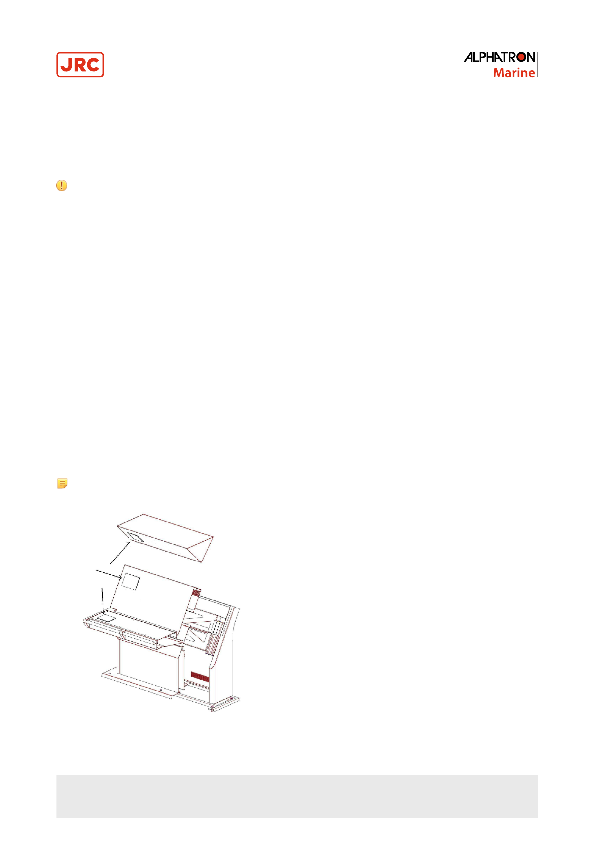
1.1.3 Mounting Instrument
The display unit can only be flush mounted. Carefully consider the location and angle of the display unit for maximum
visibility. Make sure that there is enough space to connect cables. The display unit can be installed horizontally, vertically
or under an angle, see Figure 1: Flush mounting on page 10.
Note For outdoor fitting, use appropriate sealing arrangement.
Figure 1: Flush mounting
10 | Installation Instructions
Page 11

1.1.4 Fitting Instrument Mounting Frame
Prior to fitting the display unit, install the mounting frame.
Figure 2: Mounting Frame MFM
1. Make a square hole in the (overhead) console. Use the provided template. For dimensions, see Mechanical Drawing
MFM on page 50.
2. Push the mounting frame into the hole and attach it with four screws.
3. Push the display unit into the mounting frame.
Note The instrument is locked into position by a spring system.
Note Use the Overhead Mounting Kit for securing the display unit to an overhead console, to prevent the unit
from falling out.
1.1.5 Fitting Instrument Water Seal
The instrument can be positioned outside, using a water seal. To apply the water seal, use the IP56 Kit and follow the
mounting instructions below.
The IP56 Kit for MFM consists of the following items:
• 1 gasket MFS
• 4 adapters M3-M6
• 4 lock washers M6
• 4 hex nuts M6
11 | Installation Instructions
Page 12
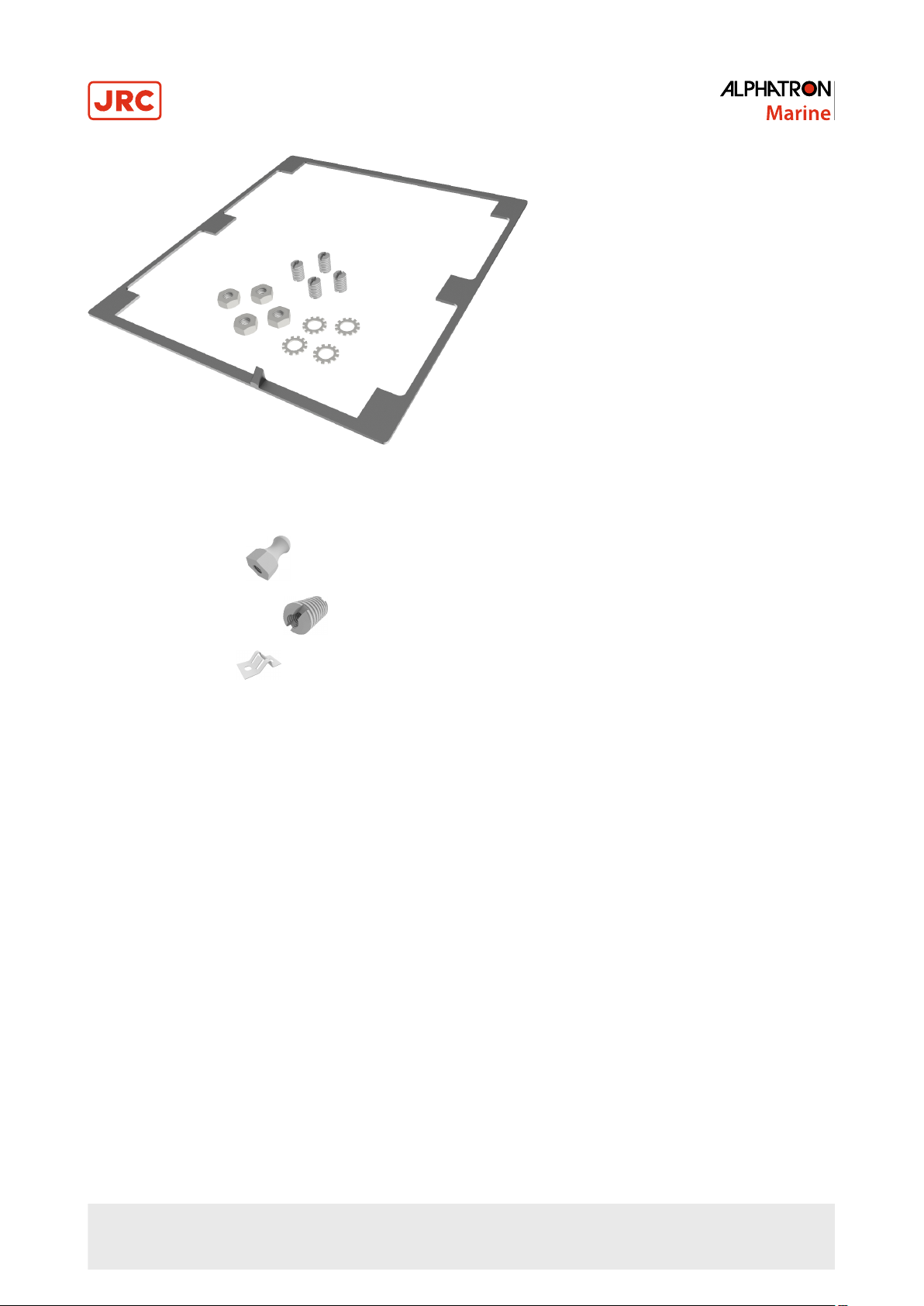
Figure 3: IP56 Kit for MFM
Mounting instructions:
1.
Remove the 4 snaps ( ) from the instrument.
2.
Add the 4 adapters M3-M6 ( ) to the instrument.
3.
Remove the 4 clips ( ) from the bracket.
4. Apply the gasket to the instrument.
INFO: Pay special attention to the small protruding cam, so that it fits exactly in the gap in the front panel.
5. Place the instrument in the bracket.
6. Mount the 4 lock washers and hex nuts.
1.1.6 Instrument Electric Connections
All AlphaLine instrument versions share the same electronics with identical connections.
For pin-outs, see Table 4: Serial Connector P12 (8 pins) on page 17 and Table 5: Serial Connector P19 (12 pins) on
page 17.
1.1.7 Cable
Use the following connection cables:
12 | Installation Instructions
Page 13
Name Specification Shield
(Y/N)
Power 2 x 1.5 mm
USB USB Y
2
Y IEC 60092-352
Norm
Serial
3 x 2 x 0.5 mm2 (inside cabinets)
3 x 2 x 0.75 mm2 (ship's cabling)
2 x 2 x 0.5 mm2 (inside cabinets)
Serial
2 x 2 x 0.75 mm2 (ship's cabling)
Ethernet Ethernet CAT 5e S/FTP Y
Table 3: Connection Cables
Y
Y IEC 61162-1
IEC 61162-2
1.1.8 Cable Preparation
Cable preparation and cable connections as described in this manual are essential for the correct functioning of the
instrument.
Note There are two type of cable sides (connections): sending cable sides and receiving cable sides. Normally,
the cable shield will be grounded only at the sending side of the cable. For a power cable, this is the power
supply side. For a data cable, this is the Tx side of the cable. For combined Tx/Rx cables, either side can be
grounded, but beware of grounding only one side.
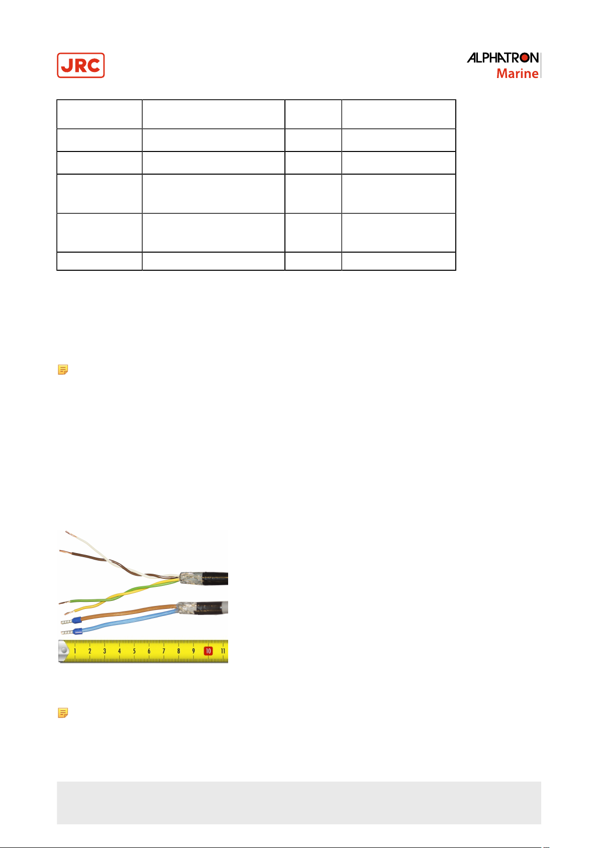
1.1.8.1 Cable Preparation Sending Sides
1. Remove approx. 80 mm of the plastic cable sheath, including the grounding shield.
2. Cut away approx. half of the length of the now visible cable shield and fold the remaining shield back over the cable
sheath.
3. Wrap insulating tape over half of the visible grounding shield.
4. Attach the remaining visible grounding shield to the metal saddle on the rear of the instrument. See Figure 4: Cable
Preparation Sending Cable Sides on page 13.
Figure 4: Cable Preparation Sending Cable Sides
Note Always check the drawing for the correct shielding of signals.
13 | Installation Instructions
Page 14
1.1.8.2 Cable Preparation Receiving Sides
1. Remove approx. 80 mm of the plastic cable sheath, including the grounding shield.
2. Wrap insulating tape over the cable end.
3. Attach the isolated cable end to the metal saddle on the rear of the instrument. See Figure 5: Cable Preparation
Receiving Cable Sides on page 14.
Figure 5: Cable Preparation Receiving Cable Sides
Note Always check the drawing for the correct shielding of signals.
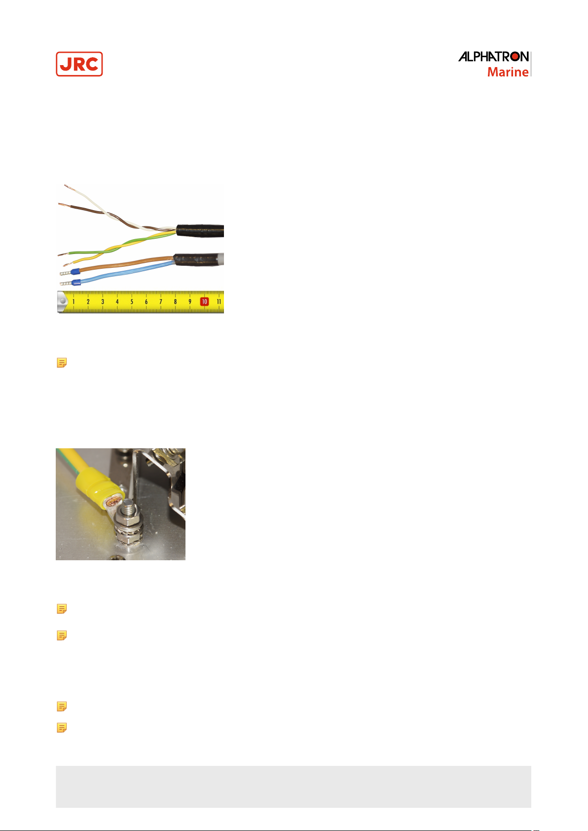
1.1.9 Grounding Instrument
To function properly, the AlphaLine instrument must be grounded to the ship’s mass.
For this purpose the instrument has a grounding bolt. Connect the grounding bolt to the ship’s mass with a low
impedance connection.
Figure 6: Grounding Bolt
Note The grounding strap must be as short as possible. If wire is used, use a minimum of 2.5 mm2 copper wire.
See Figure 6: Grounding Bolt on page 14.
Note Always check the drawing for the correct shielding of signals.
1.1.10 Instrument Power Supply
The AlphaLine instrument has one 24 VDC (nominal) power input. Power consumption is approx. 500 mA. Connect to a
power supply > 1 A.
Note The power supply input is protected against connecting to the wrong polarity.
Note In rush current approximately 4 A.
14 | Installation Instructions
Page 15
1.1.11 Serial Interfaces
This chapter provides extra information about the serial interfaces used in the Marine Electronics.
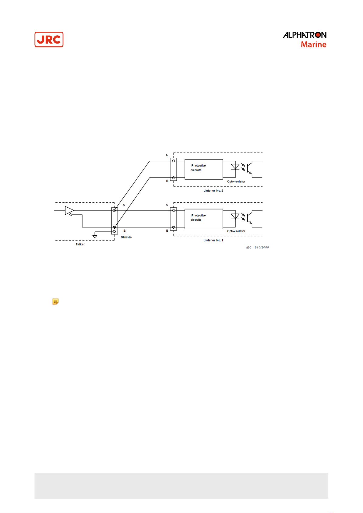
• IEC 61162-1
This standard is the most commonly used. In the standard, the sender (Tx side) and receiver (Rx side) are referred to
as talker and listener.
It has the following characteristics:
• Communication speed: baud rate of 4800, 8 databits, 1 stop bit, no parity.
• One talker (Tx side, commonly a sensor such as GPS) may be connected to one or more listeners (Rx side, e.g.
displays or computer systems such as ECDIS). The circuit looks as shown in Figure 7: IEC 61162-1 Circuits on
page 15.
Figure 7: IEC 61162-1 Circuits
There are some requirements to the wiring of the signal.
• Tx+ and Tx– are connected to Rx+ and Rx– respectively.
• On the transmitting side the shield of the cable is connected to earth , and is NOT connected on the listener side.
Note In case the NMEA signal is connected both ways, two cables should be used with proper shielding
as described above. (It is just above situation times two for the opposite direction).
Only one talker is connected to the bus, and multiple listeners may be connected to the same bus without the need
for a signal isolator/multiplier. However, it is not forbidden and good practice to use a multiplier since it eliminates
possible faults caused by short circuiting of the signal by a faulty listener. Alphatron is able to supply such a multiplier
if needed (NMEA Distribution Interface Mk.2).
• IEC-61162-2
This standard is applied to provide better characteristics when the data transmission speed is higher.
It has the following characteristics:
• Communication speed: baud rate of 38400, 8 databits, 1 stop bit, no parity.
• One talker (Tx side, commonly a sensor such as GPS) may be connected to one or more listeners (Rx side, e.g.
displays or computer systems such as ECDIS). The circuit looks as shown in Figure 8: IEC 61162-2 Circuits on
page 16.
15 | Installation Instructions
Page 16
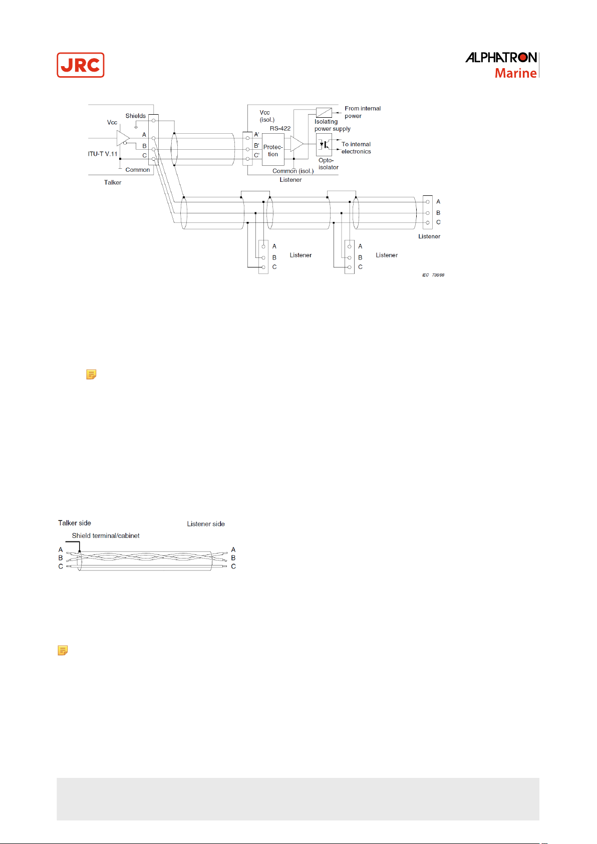
Figure 8: IEC 61162-2 Circuits
The main difference with the IEC 61162-1 standard is that a COMMON signal is added here for a good reference to
isolated ground.
• Tx+ and Tx– are connected to Rx+ and Rx– respectively.
• The shield of the cable is connected to the earth on the transmitting side, and is NOT connected on the listener.
Note In case the NMEA signal is connected both ways, two cables should be used with proper shielding
as described above. (It is just above situation times two for the opposite direction).
Only one talker is connected to the bus, and multiple listeners may be connected to the same bus without the need
for a signal isolator/multiplier. However, it is not forbidden and good practice to use a multiplier since it eliminates the
possible faults caused by short circuiting of the signal by a faulty listener. Alphatron is able to supply such a multiplier
if needed (NMEA Distribution Module Mk.2)
The cable should be of a shielded type, and the shield connected to the earth on the talker side and NOT to earth on the
listener side.
The IEC 61162 specifies a number of different cables which can be used. Of these cables, Alphatron recommends to use
single shielded cable, as shown in Figure 9: Single Shielded Cable on page 16.
Figure 9: Single Shielded Cable
So, for a two way connection two times 3 wire cable is used with shield connected on the talker side.
Note For Modbus we recommend to use the IEC 61162-2 connections on equipment. IEC 61162-1 ports are
also usable and tested to work with Modbus on speeds up to 38400 baud, however the IEC 61162-2 ports are a
little better suited because of the C wire for signal ground reference.
1.1.12 Serial Connection
The AlphaLine instrument has four IEC 61162 serial ports with Transmit (Tx) and Receive (Rx) connections. Three ports
are of type IEC 61162-1, one port is of type IEC 61162-2.
The instrument has two serial connectors, connector P12 with 8 connections and connector P19 with 12 connections.
16 | Installation Instructions
Page 17
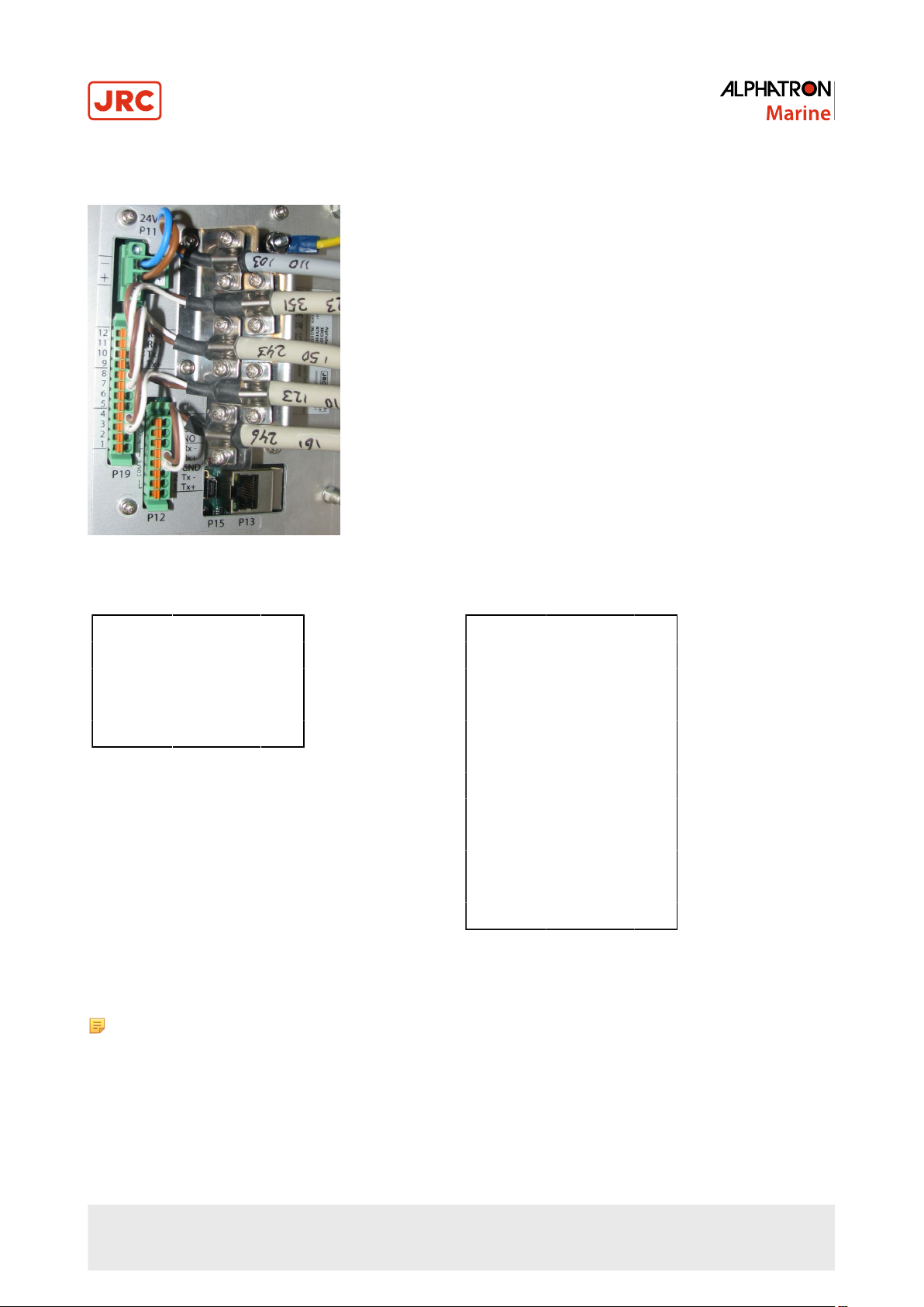
For pin connections, see Figure 10: Serial pin connections on page 17, Table 4: Serial Connector P12 (8 pins) on
page 17 and Table 5: Serial Connector P19 (12 pins) on page 17.
Figure 10: Serial pin connections
1 COM0 IEC 61162-2 Tx+
2 COM0 IEC 61162-2 Tx–
3 COM0 IEC 61162-2 GND
4 COM0 IEC 61162-2 Rx+
5 COM0 IEC 61162-2 Rx–
Table 4: Serial Connector P12 (8 pins)
Note The instrument should always be connected according to the cable diagram. See Electric Diagrams on
page 51. Ensure connection to the correct COM port.
1.1.13 Relay
1 COM1 IEC 61162-1 Tx+
2 COM1 IEC 61162-1 Tx–
3 COM1 IEC 61162-1 Rx+
4 COM1 IEC 61162-1 Rx–
5 COM2 IEC 61162-1 Tx+
6 COM2 IEC 61162-1 Tx–
7 COM2 IEC 61162-1 Rx+
8 COM2 IEC 61162-1 Rx–
9 COM3 IEC 61162-1 Tx+
10 COM3 IEC 61162-1 Tx–
11 COM3 IEC 61162-1 Rx+
12 COM3 IEC 61162-1 Rx–
Table 5: Serial Connector P19 (12 pins)
One relay output is available for legacy alarm monitoring systems without serial ALR connection. This AlphaLine
instrument relay output is located on the 8-pin connector on the following pins. Use the NC (Normally Closed), or NO
(Normally Open) connection depending on the application.
For pin lay out, see Table 6: Relay Connector P12 (8 pins) on page 18.
17 | Installation Instructions
Page 18
6 Relay Normally Open
7 Relay Common
8 Relay Normally Closed
Table 6: Relay Connector P12 (8 pins)
1.1.14 Connecting Serial Ports
Serial data from sensors such as GPS, Speedlog and others is commonly known as NMEA. In the regulations is referred
to the IEC standard for the correct protocol description. These are IEC 61162-1 and IEC 61162-2. The manual will use
both these standards as there is a difference between them.
For detailed information on both standards, please read the IEC-61162-1 and IEC 61161-2 documents.
Serial Port IEC Standard
COM 0 61162-2
COM 1 61162-1
COM 2 61162-1
COM 3 61162-1
Table 7: Serial Ports
To make connections: Connect the data signal to the COM port as shown in the Electric Diagrams on page 51.
18 | Installation Instructions
Page 19

1.1.15 Connecting Dimmer
AlphaLine instruments can accept IEC 61162-1 dimmer messages with the $--DDC format.
Connect the signal to the designated dimmer connector as shown on the connection diagram, see Electric Diagrams on
page 51.
Figure 11: Dimmer Message
19 | Installation Instructions
Page 20

1.2 Software Installation
The software version for this AlphaLine instrument is 1.X.
1.2.1 Selecting Active Software
The AlphaLine instrument is stocked in the warehouse with all software pre-installed. The commissioning engineer will
select the function the AlphaLine instrument requires.
When a AlphaLine instrument is started up for the first time, or after a RESET, a selection menu appears where the
required application can be selected. See Figure 12: First Start up Screen (Empty) on page 20.
Figure 12: First Start up Screen (Empty)
1. Search for the required application by touching the < or > buttons.
2. Touch the Start application button once the required application appears in the window.
The AlphaLine instrument will restart and install the selected application. This will take a couple of minutes to
complete. Please be patient.
Note DO NOT switch off or disconnect the AlphaLine instrument while installing – this will corrupt the
software and make the AlphaLine instrument inoperable.
Note When the installation has been completed, the main screen of the application will appear.
1.2.1.1 Software Applications
The selection menu shows the whole range of AlphaLine instruments applicable to this screen format and orientation,
with the name of the software application displayed in the window. This name is different from the commercial name of
the instrument. Below, you will find the correct software application name for the AlphaTurn.
Software Application Name Commercial Name Instrument
ROT_MED_6,5_PT_SEA AlphaTurn
Table 8: MFM Software Applications
20 | Installation Instructions
Page 21

1.2.2 Software Updates
Alphatron Marine is constantly improving and updating its products by developing new functionalities and improving
usability and performance.
Visit our support website www.jrc.am/support for the newest manuals and to check that your product is still running the
latest software. Due to the nature of our products and solutions, software and relevant instructions will be available to
authorized distributors and dealers only.
Software update files and procedures are made available by Alphatron and can be acquired from the Alphatron Service
Desk at www.jrc.am/support.
Note DO NOT shut down the device during an update procedure, because this can cause irreversible damage
to the files on the internal storage device.
1.2.3 Watchdog Protection
AlphaLine display unit is guarded by a watchdog application. When the software freezes for an unknown reason,
then after a pre-programmed period, the display unit will restart itself and ensures that the display unit is functional
continuously.
Watchdog application is fed by a task with the lowest priority in a multitask environment. See Figure 13: Watchdog
Application on page 21. If one task freezes, the scheduler performs a context switch to other tasks with the same or
higher priority. This way, the task with a lowest level will not be scheduled and the watchdog will not be fed. And finally,
the watchdog will reset the processor.
21 | Installation Instructions
Figure 13: Watchdog Application
Page 22

2 Operation
2.1 Power
The unit must be connected to the power at all times.
Use the power button in the front panel of the instrument to switch the power ON and OFF.
Note In the OFF position, the power button is still dimly lit for easy identification in the dark. This only applies
when the instrument is connected to the power supply.
Note In a blackout situation, the instrument will always return to the last power state. This means that if the
instrument was switched ON before a blackout, it will be ON after a blackout. The same applies to the OFF
status. When the instrument is switched ON, the power button is lit in accordance with the DIM setting of the
LCD backlight, so the power buttons dims together with the LCD panel.
2.2 Main Screen
When the AlphaLine Instrument is switched ON, it will boot into the AlphaLine Instrument application. The application will
show the instrument specific data applicable to the particular instrument.
During the initialization time, while the instrument is starting up, the screen displays Figure 14: Splash Screen Rate of
Turn Indicator on page 22 . Depending on the display, the lower half of the screen shows the size of the instrument.
Figure 14: Splash Screen Rate of Turn Indicator
After the initialization time has been completed, the main screen appears. The main screen displays four standard
buttons. See Figure 15: Main Screen AlphaTurn on page 23 and Table 9: Main Screen Buttons on page 23.
22 | Operation
Page 23

Figure 15: Main Screen AlphaTurn
Functionality of the buttons is as described in table below.
Shows the instrument is functioning normally. If there's a malfunction a colored alert
symbol will show here.
Opens the MENU, where settings can be adjusted. This button also shows the
functionality of the instrument by rotating. If it stops rotating, the software of the
instrument is either very busy or it has crashed.
Touching this button will set the LCD DIM level brighter.
Touching this button will set the LCD DIM level one step less bright.
Table 9: Main Screen Buttons
23 | Operation
Page 24

2.3 Menu Handling
Menu handling is standardized for all different menu screens and for all different instruments. See Figure 16: Menu
Example on page 24 for an example of the MENU and Table 10: Explanation of On-screen Buttons and Icons on
page 24 for an explanation of the on-screen buttons and icons.
Figure 16: Menu Example
Go to main screen. Touch again to go to MENU.
Go back to the previous screen without saving settings.
Undo the last value change.
Accept and save current settings and applied settings will be saved.
Undo all settings and exit MENU
Scroll between standard settings using the + or – button
Standard settings are divided into several screens. Navigate through these screens
using the < or > button.
Table 10: Explanation of On-screen Buttons and Icons
24 | Operation
Page 25

2.3.1 Default Values AlphaLine Instrument
When the AlphaTurn is reset, it will return to the start-up screen, where a new instrument can be selected. The newly
selected instrument will contain the default values.
The default values for the AlphaTurn are shown in the table below.
Menu -> Theme
Illumination DAY
Menu -> Date_Time [1/2]
Year Compulsory Input
Month Compulsory Input
Day Compulsory Input
Menu -> Date_Time [2/2]
Hour Compulsory Input
Minutes Compulsory Input
Time Zone Compulsory Input
Menu -> ROT_Set
Menu -> ADV_SET -> CNTRL_DIM
Menu -> ADV_SET -> Eth_Config
Menu -> ADV_SET -> UART Config [1/2]
ROT Damping DISABLED
Damping Time (s) 1
INPUT ON
IP Address 192.168.31.31
Subnet Mask 255.255.255.0
Gateway 192.168.31.1
UART UART 0
Parity NONE
Stop Bits 1
Menu -> ADV_SET -> UART Config [2/2]
25 | Operation
Data Bits 8
Baud Rate 4800
Page 26

Protocol NMEA
Menu -> ADV_SET -> NMEA_TALKER
TALKER **
USED / UNUSED USED
Menu -> ADV_SET -> ROT_Set
MODBUS DISABLED
Menu ->ADV_SET ->NMEA_SET
SENTENCE NONE
INTERVAL [ms] 1000
PORT OFF
Table 11: Default Values for AlphaTurn
2.4 Indication Handling
If a malfunction occurs, a visual notification (=Important Indication) will be displayed.
For indication handling while operating the MAIN screen, see Figure 17: Indication Handling in Main Screen (example)
on page 27.
26 | Operation
Page 27

Figure 17: Indication Handling in Main Screen (example)
For indication handling while operating the MENU, see Figure 18: Indication Handling in Menu (example) on page 28.
27 | Operation
Page 28

Figure 18: Indication Handling in Menu (example)
28 | Operation
Page 29

Icon
Number
Table 12: Indication Management Icons
Icon Name Icon Description
0 Normal Condition Stationary circle with gray tick mark
1 Important Indication Yellow message icon and indication text. Touching
this icon toggles the visibility of the indication text.
Icon Graphic
(on display unit)
29 | Operation
Page 30

2.5 Settings
All instruments have generic and advanced settings.
All users are authorized to use the generic settings. Only the commissioning engineer has access to the advanced
settings, which are only needed during commissioning or troubleshooting.
2.5.1 Generic Settings
Every user of the AlphaLine instrument can access the generic settings.
2.5.1.1 Generic Settings Menu
Touch the MENU button in the main screen to enter the MENU with generic settings, see Figure 19: Generic Settings
Menu on page 30.
Figure 19: Generic Settings Menu
Select the button to configure a specific setting, or touch the ← button to return to the main screen.
30 | Operation
Page 31

2.5.1.2 Touch Screen Calibration (TOUCH CAL)
The touch screen can be calibrated by following the instructions that appear on the screen.
Figure 20: Touch Screen Calibration
Menu
1. In the MENU, touch the TOUCH CAL button.
The TOUCH SCREEN CALIBRATION MENU appears, see Figure 20: Touch Screen Calibration Menu on page
31.
2. Calibrate the screen by touching the CONFIRM CALIBRATE THE TOUCH SCREEN button.
The calibration screen appears with text requesting to touch the four numbered reference points that appear on the
screen, see Figure 21: Calibration Reference Points on page 31.
3. Touch the four reference points in sequence 1 to 4, as they light up.
The application will determine whether the sequence is carried out correctly.
4. If the text VALID CALIBRATION appears, then the calibration is performed accurately. Test calibration for accuracy
by dragging a finger across the screen, see Figure 22: Calibration Lines on page 31.
The line that appears on the screen should follow the finger.
5. Touch the ACCEPT button if calibration appears to be correct, or touch the AGAIN button to repeat the calibration
process.
6. If the text INVALID CALIBRATION...PLEASE RETRY appears, touch the AGAIN button to repeat the calibration
process.
Figure 21: Calibration Reference
Points
Figure 22: Calibration Lines
31 | Operation
Page 32

2.5.1.3 Cleaning Display ( CLEAN MODE )
The purpose of CLEAN MODE is to clean the surface of the display unit without accidentally activating a function. When
the CLEAN MODE is started, the touch screen will be deactivated for 60 seconds. Within this period the instrument
will remain functional, but it is not operable. Except when an alarm is activated, then the touch screen will be activated
immediately and the instrument will be operable again.
Figure 23: Clean Screen Menu Figure 24: Clean mode Countdown (Example)
To start CLEAN MODE, perform the following actions:
1. Touch the CLEAN MODE button in the MENU.
The CLEAN SCREEN screen appears, see Figure 23: Clean Screen Menu on page 32.
2. Touch the CONFIRM CLEANING THE SCREEN button to start the CLEAN MODE.
The AlphaLine instrument switches to the CLEAN MODE COUNTDOWN page and starts the countdown sequence,
see for example Figure 24: Clean mode Countdown (Example) on page 32.
Note For safety reason, if an alert is active and needs attention of the operator, CLEAN MODE can not be
started.
The touch screen is now deactivated and surface can be cleaned. After 60 seconds, or at an active alert, the instrument
will become operable again.
32 | Operation
Page 33

2.5.1.4 Change Theme (THEME)
2.5.1.4.1 Change Illumination
Contrast brightness can be easily adjusted to Day, Dusk and Night settings.
Figure 25: Theme
1. In the MENU, touch the THEME button.
The THEME MENU appears, see Figure 25: Theme on page 33 .
2. Touch the + or – buttons to select the desired ILLUMINATION value.
INFO: Three different ILLUMINATION values can be selected, in accordance with ambient light; DAY, DUSK and
NIGHT.
3. Touch the √ button to confirm the chosen setting.
The MENU appears again.
33 | Operation
Page 34

2.5.1.5 Change Date and Time (DATE/TIME)
The date and time can be adjusted.
Figure 26: Date/Time Screen 1 Figure 27: Date/Time Screen 2
1. In the SETTINGS screen, touch the DATE/TIME button.
The DATE/TIME screen appears, see Figure 26: Date/Time Screen 1 on page 34.
2. Touch the + and – buttons to set the correct DATE values.
3. Touch the > button to select the TIME screen, see Figure 27: Date/Time Screen 2 on page 34.
4. Touch the + and – buttons to set the correct TIME values.
5. Touch the √ button to confirm the chosen values and return to the SETTINGS screen.
6. To abort, touch the ← button to return to the SETTINGS screen.
34 | Operation
Page 35

2.5.1.6 About the AlphaLine instrument (ABOUT)
The ABOUT screen contains the name and version of the software and when it was built.
Figure 28: About the ROT Indicator
1. In the MENU, touch the ABOUT button.
The ABOUT MENU appears, see for example Figure 28: About the ROT Indicator on page 35 .
Note When asking for manufacturer's support, this information will be useful.
2. Touch the ← button to return to the SETTINGS screen.
35 | Operation
Page 36

2.5.1.7 ROT Settings (ROT SET)
The purpose of ROT Damping is to dampen the result on the screen when the ship is unstable.
Figure 29: ROT Damping Menu
To set up the ROT Damping settings, execute the following procedure:
1. In the MENU touch the ROT SET button.
The ROT DAMPING MENU appears, see Figure 29: ROT Damping Menu on page 36.
2. Set DAMPING to DISABLED or ENABLED by touching the + or – buttons.
3. Set the DAMPING TIME by touching the + or – buttons.
INFO: Set the DAMPING TIME to 1 - 10 seconds for sea application.
4. Touch the √ button to confirm the chosen setting.
The MENU appears again.
36 | Operation
Page 37

2.5.2 Advanced Settings
The advanced settings are password protected and are for use by commissioning engineers only.
2.5.2.1 Advanced Settings Menu (ADV SET)
A password is required to open the menu.
Figure 30: Password Screen
Figure 31: Advanced Settings Menu
1. In the MENU, touch the ADV SET button.
The PASSWORD screen appears, see Figure 30: Password Screen on page 37.
2. Key in the password and confirm with the √ button.
The ADVANCED SETTINGS MENU appears, see Figure 31: Advanced Settings Menu on page 37 .
3. Select the button to configure a specific setting, or touch the ← button to return to the MENU.
37 | Operation
Page 38
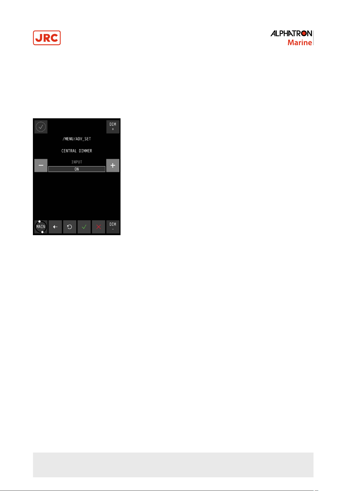
2.5.2.2 Central Dimming (CNTRL DIM)
The AlphaLine instrument supports central dimming as a listener (slave) from a standard (IEC 61162-1) dimming
sentence.
This dimming signal should be connected to serial port COM3, see Table 5: Serial Connector P19 (12 pins) on page 17.
Also see Figure 10: Serial pin connections on page 17.
If a central dimmer is connected, it can be enabled through the CENTRAL DIMMER menu, see Figure 32: CENTRAL
DIMMER menu on page 38.
Figure 32: CENTRAL DIMMER menu
1. In the MENU, touch the ADV SET button.
The PASSWORD screen appears.
2. Key in the password and confirm with the √ button.
The ADVANCED SETTINGS MENU appears.
3. Touch the CNTRL DIM button.
The CENTRAL DIMMER screen appears, see Figure 32: CENTRAL DIMMER menu on page 38.
4. Touch the + or – button next to INPUT to select ON or OFF.
5. Touch the √ button to confirm the chosen setting.
38 | Operation
Page 39

2.5.2.3 Ethernet Configuration (ETH CONFIG)
The AlphaLine instrument has one network interface to connect to a ship's network.
This can be useful when the instrument is connected to a remote interface or a PLC which uses Modbus/TCP. The
Ethernet interface can also be used for IEC 611612-450 signals.
Note This option has been included for future use.
Figure 33: Ethernet Menu Figure 34: Numeric Pad
1. In the MENU, touch the ADV SET button.
The PASSWORD screen appears.
2. Key in the password and confirm with the √ button.
The ADVANCED SETTINGS MENU appears.
3. Touch the ETH CONFIG button.
The ETHERNET screen appears, see Figure 33: Ethernet Menu on page 39.
4. Touch the bar below IP ADDRESS, SUBNET MASK, or GATEWAY to change these.
The numeric pad appears every time one of the bars is touched, see Figure 34: Numeric Pad on page 39.
5. Touch the numbers to insert new numbers and touch the X button to delete numbers.
6. Touch the √ button when numbers are correct.
7. Touch the √ button again to confirm the IP ADDRESS, SUBNET MASK and GATEWAY settings.
39 | Operation
Page 40

2.5.2.4 Serial Port Configuration (UART CONFIG)
The AlphaLine instrument is equipped with 4 serial ports (also called UART or COM).
The settings of the serial ports are divided over two screens as shown in Figure 35: UART Screen 1 on page 40 and
Figure 36: UART Screen 2 on page 40. Use the < or > button to toggle between the screens.
The default setting for NMEA (IEC 61162-1) data is 4800 baud, 8 databits, 1 stopbit. The default setting for Modbus over
serial port is 19200 baud, 8 databits, 1 stopbit and EVEN parity. See also Default Values AlphaLine Instrument on page
25.
Select and configure NMEA when a sensor is connected with the standard NMEA signals. Select ModbusMaster when
an interface (such as Analog Interface Mk.2 or AlphaTurn Interface Mk.2) is used.
Figure 35: UART Screen 1 Figure 36: UART Screen 2
1. In the MENU, touch the ADV SET button.
The PASSWORD screen appears.
2. Key in the password and confirm with the √ button.
The ADVANCED SETTINGS MENU appears.
3. Touch the UART CONFIG button.
The UART screen 1 appears, see Figure 35: UART Screen 1 on page 40.
4.
• Touch the + or – button to set UART from 0 to 3.
• Touch the + or – button to set PARITY to ODD, EVEN, FORCED 0, FORCED 1, NONE.
• Touch the + or – button to set STOP BITS to 1 or 2.
5. Touch the > button to toggle to screen 2, see Figure 36: UART Screen 2 on page 40 and follow the same principle
as for screen 1. Touch the < button to return to screen 1.
6. Touch the √ button when the settings are correct.
7. If settings are modified, restart the instrument to initialize the serial port again.
40 | Operation
Page 41

2.5.2.5 Serial Port Monitor (SERIAL MON)
It is possible to show serial data transmitted and received over the serial ports.
Usually, NMEA signals should be viewed as ASCII data and Modbus data should be viewed as HEX data. Received data
as well as sent data can be viewed (but not simultaneously). Select the appropriate button (Tx/Rx). For NMEA, Rx is
normally used.
Figure 37: Serial Port 1 Figure 38: Serial Port 3
1. In the MENU, touch the ADV SET button.
The PASSWORD screen appears.
2. Key in the password and confirm with the √ button.
The ADVANCED SETTINGS MENU appears.
3. Touch the SERIAL MON button.
The SERIAL PORT MONITOR 1 screen appears, see Figure 37: Serial Port 1 on page 41.
4. Touch the < or > buttons to select next port, see Figure 38: Serial Port 3 on page 41.
5. Touch the Rx/Tx buttons to show the Received/Transmitted data.
6. Touch the ASCII/HEX buttons to show the characters in ASCII code or in HEX values.
7. Touch the ← button to return to ADVANCED SETTINGS MENU.
Note All serial ports are configured the same way, the Serial Port screen has the following options:
• Baud rate: - Baud rate is a setting for Modbus devices, NMEA talkers, and other devices. It is also known
as symbol rate and modulation rate. The term roughly means the speed that data is transmitted. It is a
derived value based on the number of symbols transmitted per second. Valid values are: 1200, 2400,
4800, 9600, 19200, 38400, 57600 or 115200. The default value for NMEA is 4800. The default value for
Modbus communication is 19200.
• Data bits: - The numbers of data bits in each character can be 7 (for true ASCII), 8 (for any kind of data,
as this matches the size of a byte) 8 data bits are almost universally used in newer applications. 7 bits
is only used on special occasions. Valid values are: 7 or 8. The default value for NMEA and Modbus
communication is 8.
• Stop bits: - Stop bits sent at the end of every character allow the receiving signal hardware to detect the
end of a character and to resynchronize with the character stream. Electronic devices usually use one
stop bit. Valid values are: 1 or 2. The default value for NMEA and Modbus communication is 1.
41 | Operation
Page 42

• Parity: - Parity is a method of detecting errors in transmission. When parity is used with a serial port, an
extra data bit is sent with each data character, arranged so that the number of 1 bits in each character,
including the parity bit, is always ODD or always EVEN. If a byte is received with the wrong number of 1's,
then it must have been corrupted. However, an EVEN number of errors can pass the parity check. Valid
values are: N ( None ), O ( Odd ) or E ( Even ). The default value for NMEA is N (None). The default value
for Modbus communication is E (Even).
2.5.2.6 Factory Reset (RESET)
All menu settings can be reset to the factory default setting. For an overview of the default settings, see Default Values
AlphaLine Instrument on page 25.
Figure 39: Execute Factory Reset Figure 40: First Start-Up Screen
1. In the MENU, touch the ADV SET button.
The PASSWORD screen appears.
2. Key in the password and confirm with the √ button.
The ADVANCED SETTINGS MENU appears.
3. Touch the RESET button.
The EXECUTE FACTORY RESET screen appears, see Figure 39: Execute Factory Reset on page 42.
4. Touch the CONFIRM RESET ALL SETTINGS TO FACTORY DEFAULTS button for a full reset to factory default
values.
The AlphaLine instrument reverts to the first start-up screen, see Figure 40: First Start-Up Screen on page 42.
5. To return to the previous menu screen, touch the ← button.
42 | Operation
Page 43

2.5.2.7 Log (LOG)
The log screen shows information useful for fault finding.
Figure 41: Log Screen
1. In the MENU, touch the ADV SET button.
The PASSWORD screen appears.
2. Key in the password and confirm with the √ button.
The ADVANCED SETTINGS MENU appears.
3. Touch the LOG button.
The log screen appears, see Figure 41: Log Screen on page 43.
4. Touch the ˅ or ˄ buttons to scroll through the readings.
5. Take a picture of the log screen and contact the Alphatron Service Desk at www.jrc.am/support about errors.
Note Use for example a mobile phone to take a picture.
6. Touch the ← button return to the ADVANCED SETTINGS MENU.
INFO: Touching the MAIN button takes you back to the main screen.
43 | Operation
Page 44

2.5.2.8 NMEA Talker (NMEA TALKER)
With this menu, some additional NMEA sentence filters can be applied on the address field of an NMEA sentence. The
address field consists of a talker ID and a sentence formatter (for example ROT). This is depending on the configuration
of the software.
• TALKER- This item is prepared for future expansion, it is now set to **, which means that the NMEA (IEC61162-1)
Talker ID is not checked. Any talker ID is always accepted with the selected sentence formatter.
• USED/UNUSED - This setting defines the acceptation of the sentence based on the combination of the selected
Talker ID and selected sentence formatter. If this is set to UNUSED all sentences formatted with the selected Talker
ID are ignored. For now, this makes it possible for example to reject some specific sentence formatter.
Figure 42: NMEA Talker Menu
1. In the MENU, touch the ADV SET button.
The PASSWORD screen appears.
2. Key in the password and confirm with the √ button.
The ADVANCED SETTINGS MENU appears.
3. Touch the NMEA TALKER button.
4. Select the correct sentence formatter by touching the < or > buttons.
INFO: The TALKER is fixed indicated as a "Wild card" by **.
5. Touch the + or – buttons to select USED or UNUSED.
6. Touch the √ button to confirm.
44 | Operation
Page 45

2.5.2.9 NMEA Settings ( NMEA SET )
The AlphaLine instrument is able to transmit NMEA sentence to the external listener.
In this software version, it only supports the sentence VBW and DDC.
Figure 43: NMEA OUTPUT
To set up the output settings, execute the following procedure:
1. In the MENU, touch the ADV SET button.
The PASSWORD screen appears.
2. Key in the password and confirm with the √ button.
The ADVANCED SETTINGS MENU appears.
3. Touch the NMEA SET button.
The NMEA OUTPUT MENU appears, see Figure 43: NMEA OUTPUT on page 45
4.
• Touch the + or - button to set SENTENCE to VBW, DDC or NONE.
• Touch the + or - button to set INTERVAL to 100, 250, 500, 1000, 2000 or BY CHANGE.
• Touch the + or - button to set PORT to OFF, UART0, UART1, UART2, UART3 or TCP.
5. Touch the √ button when the settings are correct.
Note Please refer to Supported NMEA Sentences IEC 61162 on page 49 for more details about the
supported sentences.
45 | Operation
Page 46

3 Maintenance
• NOTICE
• This product contains no operator serviceable parts. Service and repair shall only be carried out by personnel
trained and certified by ALPHATRON MARINE B.V.
• NOTICE
• When cleaning the surface, do not use any organic solvent such as thinner or benzine. Otherwise, the paint
and markings on the surface may get damaged. For cleaning the surface, remove the dust and debris and
wipe with a clean dry cloth.
46 | Maintenance
Page 47

4 Appendix A
Appendix A contains:
1. Hardware Specifications on page 48
2. Mechanical Drawings on page 50
3. Electric Diagrams on page 51
4. Schematics on page 54
47 | Appendix A
Page 48

4.1 Hardware Specifications
4.1.1 Specifications MFM
Box Contents upon Delivery
Rate of Turn Indicator MFM 3108.0096 grey / 3108.0098 black
Mounting bracket
Screws (4 pcs)
USB flash drive with manuals
Template for cut-outs
Physical Dimensions
Dimensions (WxHxD) 160x180x80 mm (6.30x7.09x3.15")
Panel cut-out (WxH) 138x172 mm (4.84x6.77")
Weight 1.23 kg (2.71 lbs)
Power Specifications
Power supply 24 VDC input +/- 20% (Single source)
Power consumption 12 W (24 VDC @ 500 mA in rush prox. 4 A)
Protection Reverse polarity protection
Start-up time 30 sec.
Operating Conditions
Operating temperature
Operating humidity Up to 95% (at 40°C)
Storage temperature -25°C to +70°C
Storage humidity Up to 95% (at 40°C)
IP rating IP56 front / IP22 back
Compass safe distance Std: 0.1m / Steering: 0.1m
Environmental according to DNV 2.4 table 2.1
Temperature Class D
Humidity Class B
Vibration Class A
EMC compatibility Class B
Enclosure Class C
-25°C to +55°C
1
Display Functionality
Font display text 7 mm (viewing distance = 2 m)
Font operation buttons 3.5 mm (viewing distance = 1 m)
Accuracy Resolution 0.1°/min
Acoustic noise level 0 db
Display Specifications
High quality TFT Touch screen 6.5"
Pixels 480 x 640 (aspect ratio 3:4)
Orientation Vertical
Light intensity Max. brightness 450 cd/m2
View angle (H/V) 140°/160°
Maximum colors 16.7 million
Input/Output Signals
COM 0 (IEC 61162-2) isolated Modbus RTU Rx/Tx
COM 1 (IEC 61162-1) isolated NMEA Rx/Tx
COM 2 (IEC 61162-1) isolated NMEA Rx/Tx
COM 3 (IEC 61162-1) isolated NMEA Rx/Tx
USB port (Mini) Used for software update/maintenance
Alarm output NOC contact (potential free)
Norms/Standards
IEC 60945 (2002) Incl. IEC 60945 Corrigendum 1 (2008)
Standard DNV 2.4 Det Norske Veritas
IEC 61162 series NMEA Definitions
IEC 62288 (2014) Testing methods
ISO 20672 (2007)
4.1.2 Available Accessories
Available Accessories
MFM IP56 Kit 3698.0018
Table 13: Available Accessories
1
Although the test conditions for bridge units provide for a maximum operation temperature of 55°C, continuous operation of all electronic components should, if
possible, take place at ambient temperature of 25°C. This is necessary for a long life and low service costs.
48 | Appendix A
Page 49

4.2 Software Specifications
4.2.1 Supported NMEA Sentences IEC 61162
Supported NMEA sentences (IEC 61162)
Primary IN $xxROT
Secondary IN $xxDDC
Secondary OUT $VDDDC
Table 14: Supported NMEA Sentences
4.2.2 Indication List
Indication list
Invalid checksum of NMEA ... sentence Checksum of incoming sentence is incorrect
Parsing of NMEA ... failed Contents of incoming sentence is incorrect
No Rate of Turn information received NMEA: Missing of correct ROT sentence (> 6 sec.)
Table 15: Indication List
49 | Appendix A
Page 50

4.3 Mechanical Drawings
4.3.1 Mechanical Drawing MFM
Figure 44: Mechanical Drawing MFM
50 | Appendix A
Page 51

4.4 Electric Diagrams
The cable diagrams and connection diagrams illustrate the connections to hardware, power and other equipment.
51 | Appendix A
Page 52

4.4.1 Cable Diagram AlphaTurn
Figure 45: Cable Diagram AlphaTurn
52 | Appendix A
Page 53

4.4.2 Connection Diagram AlphaTurn
Figure 46: Connection Diagram AlphaTurn
53 | Appendix A
Page 54

4.5 Schematics
This chapter contains the schematics of the AlphaLine instruments. The commissioning engineer uses the schematics to
be able to connect the signals according to the ship's requirements.
54 | Appendix A
Page 55

4.5.1 Schematics AlphaLine MF Display Unit
Figure 47: Schematics AlphaLine MF Display Unit
55 | Appendix A
Page 56

4.5.2 Schematics AlphaLine Instrument
1
1
2
2
3
3
4
4
5
5
6
6
H H
G G
F F
E E
D D
C C
B B
A A
Design:
Product:
Date :
Alphaline_ACB
21/01/2015
Sheet: Main.SchDoc of1 14Release
Alphatron Marine
152-01/1.5 -
DAT2
1
CD/DAT3
2
CMD
3
VDD
4
CLK
5
VSS
6
DAT0
7
DAT1
8
SWITCH A
A
SWITCH B
B
t
a
b
1
t
a
b
2
t
a
b
3
t
a
b
4
Mounting tabs
P14
Micro SD
QSPI
Memory
I2C
LCD
Touch
RS422
IO
SD
USB
Backlight
RESET
Power_feedback
ETH
Power_control
2. Controller
Vin+
Powerswitch
LED_Off_Anode
LED_Off_Cathode
Power_feedback
Power_control
Vin-
13. Power
ETH_RX_N
ETH_RX_P
ETH_TX_N
ETH_TX_P
ETH_LED_Link
ETH_LED_100M
3V3_ETH
RESET
ETH
10. Ethernet
QSPI
I2C
Memory
9. Memory
RS422
RS422_0_TX+
RS422_0_TX-
RS422_0_RX+
RS422_0_RX-
RS422_0_Shield
RS422_1_TX+
RS422_1_TXRS422_1_RX+
RS422_1_RX-
RS422_3_TX+
RS422_3_TXRS422_3_RX+
RS422_3_RX-
RS422_2_TX+
RS422_2_TXRS422_2_RX+
RS422_2_RX-
6. RS422
Touch
X-
Y+
5WSX-
Y-
X+
8. Touchscreen
IO
Joystick_push
Joystick_B
Joystick_A
Joystick_Y
Joystick_X
Potmeter_output
Motor-
Relay_NO
Relay_COM
Relay_NC
LED_On_Cathode
Buzzer_ext-
Joystick_5V
Potmeter_GND
Potmeter_3V3
Buzzer_ext+
Buzzer_int-
Buzzer_int+
5. IO
LCD
11. LCD
USB
4/5 wire touchscreen
USB_VBUS
USB_DUSB_D+
SD_DAT2
SD_DAT3
SD_DAT0
SD_DAT1
SD_CLK
SD_VDD
SD_CMD
SD_CD
SD
USB
USB_ID
7. USB_SD
TD+
1
TD-
2
RD+
3
TCT
4
RCT
5
RD-
6
Filter
8
9 10
11 12
Shield
Yellow
Green
P13
RJ45
1
2
P11
MSTBV 2,5/ 2-GF
1
2
3
4
5
6
7
8
P8
Micro Match
1
2
3
4
P6
Micro Match
1
2
3
4
5
P7
FPC 1mm
1
2
3
4
5
6
7
8
9
10
P2
FPC 1mm
P10
Solderpad
P9
1
2
3
4
5
6
7
8
9
10
P1
DF13
Backlight
EN
PWM
Cathode1
Anode1
Anode2
Cathode2
Backlight_Power
12. Backlight
Powerswitch B
Buzzer_ext +
Backlight
H3 H1
H2
H4
3V3
H2
3x IEC61162-1
Power 16-36V
Potmeter
Joystick
Motor
SD Card
Ethernet
On/Off
FID1FID2
R246 0E
R247 0E
1
2
3
4
5
Vbus
DD+
ID
GND
P15
Mini USB
1
2
3
4
5
6
7
8
P12
MCV 1,5/ 8-G-3,5-RN
1
2
3
4
5
6
7
8
9
10
11
12
P19
MCV 1,5/12-G-3,5-RN
1
2
3
4
5
6
P20
Micro Match
Relay
Rotary encoder
IEC61162-2
Buzzer_ext -
LED_On_Cathode
TP2
5016
TP3
5016
iNet Class: input isolatio n
LED_On_Anode
Connect shield to casing
12V
+
BUZ1
Internal buzzer
LVDS Connector
RGB Connector
Figure 48: Schematics AlphaLine Instrument
56 | Appendix A
Page 57

All over the world,
close to the customer
JRC/Alphatron Marine B.V.
Schaardijk 23 (harbor 115)
3063 NH Rotterdam
The Netherlands
T +31 10 453 4000 Document name: AlphaTurn
F +31 10 453 4010 Document nr. : 1000_06a
service@jrc.am Version : V1.0.8
www.jrc.am
The information in this document is subject to change without notice and
does not represent a commitment on the part of Alphatron Marine B.V.
©
All rights reserved Alphatron Marine B.V.
Centers of Excellence
Houston, Rotterdam, Singapore, Tokyo
 Loading...