

JRC Alphatron Marine Rudder Feedback Unit HD, Alphatron Marine Rudder Feedback Unit MD Installation And Operation Manual
Page 1
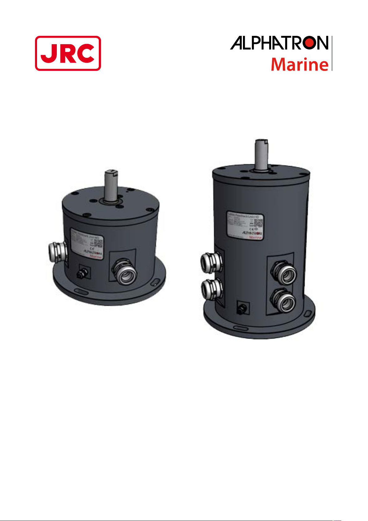
Rudder Feedback
Unit MD/HD
Installation and Operation Manual
www.jrc.am
Page 2

Contents
I Preface..........................................................................................................4
I.1 Revision History........................................................................................................................................................4
I.2 Glossary.................................................................................................................................................................... 4
I.2.1 Definitions.........................................................................................................................................................4
I.2.2 Abbreviations....................................................................................................................................................5
I.3 Norms and Standards...............................................................................................................................................6
II Warnings and Cautions............................................................................. 7
II.1 Warranty...................................................................................................................................................................8
II.2 Storage.....................................................................................................................................................................8
III Introduction................................................................................................9
1 Installation Instructions...........................................................................10
1.1 Mechanical Installation...........................................................................................................................................10
1.1.1 Supplied Parts...............................................................................................................................................10
1.1.2 Dimensions....................................................................................................................................................10
1.1.3 Installing Rudder Feedback Unit...................................................................................................................10
1.1.4 Module Electric Connections........................................................................................................................ 14
1.1.4.1 Opening Rudder Feedback Unit MD....................................................................................................14
1.1.4.2 Opening Rudder Feedback Unit HD....................................................................................................16
1.1.5 Cable............................................................................................................................................................. 18
1.1.6 Grounding Modules.......................................................................................................................................18
2 Operation...................................................................................................19
I Operating the Rudder Feedback Unit........................................................................................................................19
3 Maintenance.............................................................................................. 21
3.1 Rudder Feedback Unit Maintenance.....................................................................................................................21
3.1.1 RFU Chain Transmission Maintenance.........................................................................................................21
3.1.2 RFU Linkage Transmission Maintenance..................................................................................................... 21
4 Appendix A................................................................................................22
4.1 Specifications......................................................................................................................................................... 22
4.1.1 Specifications Rudder Feedback Unit MD/HD..............................................................................................22
4.2 Mechanical Drawings.............................................................................................................................................23
4.2.1 Mechanical Drawing Rudder Feedback Unit MD..........................................................................................23
4.2.2 Mechanical Drawing Rudder Feedback Unit HD..........................................................................................24
4.2.3 Mechanical Drawing RFU Linkage Transmission..........................................................................................25
4.2.4 Mechanical Drawing RFU Chain Transmission.............................................................................................26
4.3 Electric Diagrams...................................................................................................................................................27
4.3.1 Connection Diagram Rudder Feedback Unit MD......................................................................................... 28
4.3.2 Connection Diagram Rudder Feedback Unit HD..........................................................................................29
4.4 Thales Certificates................................................................................................................................................. 30
2 | Contents
Page 3

4.4.1 Thales Certificate Rudder Feedback Unit MD..............................................................................................30
4.4.2 Thales Certificate Rudder Feedback Unit HD..............................................................................................31
5 Appendix B................................................................................................32
5.1 ISO 9001 Certificate Alphatron Marine R&D.........................................................................................................32
6 Appendix C................................................................................................33
6.1 EC Declaration of Conformity................................................................................................................................33
3 | Contents
Page 4

I Preface
The Rudder Feedback Unit is a high quality, ruggedized, easy to install rudder feedback unit.
• Thoroughly read this instruction manual before installation and operation of the equipment.
• We recommend to keep this manual nearby the equipment to ensure ready access to it.
I.1 Revision History
Revision No. Description Date
V1.0 First issue 2 March 2016
I.2 Glossary
The glossary contains a list of definitions and a list of abbreviations.
I.2.1 Definitions
The meaning of standard definitions as used in this manual are explained in Table 1: Definitions on page 4.
Redundant A device that is equipped with multiple part of the same type, for example a double pow-
er supply. This equipment will continue to function when one of the redundant part fails.
Heading users Navigation equipment that uses heading/course information for functioning.
Hardware The physical parts of the AlphaLine instrument.
LEDs Light-emitting diodes. These are used for signaling statuses of hardware and software
signals to the user.
Central alarm system /
Bridge watch monitoring
NMEA protocol Protocol standard for transmitting and receiving of asynchronous serial data sentences.
Talker Device which transmits data. This is usually called transmitter or TX.
Listener Device which receives data. This is usually called receiver or RX.
ISO GND Isolated Ground. This is a ground connection to be used for reference signal. It is differ-
Grounding point/stud Point on the chassis of the AlphaLine instrument which should be connected to the ship's
Printed Circuit Board A printed circuit board, or PCB, is used to mechanically support and electrically connect
(Galvanic) isolated Electrical separation of two circuits. There is no current flowing directly from one circuit
CAN bus Controller Area Network. This is a network based serial bus system used for exchanging
Reverse polarity protection This is a part of the power supply hardware that prevents any damage to the equipment
System that is connected to all vital systems on a ship and that is able to give a central-
ized indication of the (alarm)status of all connected systems.
ent from EARTH and should normally not be connected to EARTH.
mass.
electronic components using conductive pathways, or traces, etched from copper sheets,
laminated onto a non-conductive substrate.
to another. Electrical energy and/or information can still be exchanged between the sec-
tions by other means, such as by induction or by optical means (like transformers or opto
couplers).
information. It is the advanced version of RS485/422 serial buses.
when the power supply is connected to the wrong polarity.
ROT signal Rate Of Turn (ROT) signal indicates the course change of a ship in degrees per minute.
This signal can be analog using voltage or current, or can be an NMEA data signal.
Heading/bearing repeaters Navigation type of instruments displaying the heading/course of a ship.
4 | Preface
Page 5

Baud rate This is the transmission speed of serial interfaces in characters per second.
Transmitting interval The frequency at which complete NMEA sentences are being transmitted in number of
times per second.
Factory setting Instrument setting for backlight color, language, number of connected apparatus, etc. as
configured as a new instrument by the factory.
Flash memory Non-volatile type of memory. This type of memory retains its contents even when the in-
strument is turned off.
Firmware (Embedded) software inside the processors of the AlphaLine instrument.
Compass safe distance The minimum distances to equipment that will not cause an unacceptable deviation of
the ship's standard and steering compasses.
Table 1: Definitions
I.2.2 Abbreviations
Abbreviations as used in this manual are explained in Table 2: Abbreviations on page 5.
A Ampere
ARD AlphaLine Repeater Display
CAN Controller Area Network
CT Chain Transmission
DC Direct Current
DP Dynamic Position
ECDIS Electronic Chart Display Information System
GPS Global Positioning System
I/O Inputs and Outputs
I.S. Inter Switch
LED Light-Emitting Diode
LT Linkage Transmission
mA Milliampere
mm Millimeter
NC Normally Closed
NMEA National Marine Electronics Association
NO Normally Open
OA Operational Alarm
TAP Type Approval Program
PCB Printed Circuit Board
RCU Remote Control Unit
RFU Rudder Feedback Unit
RFU HD Rudder Feedback Unit High Duty
5 | Preface
Page 6

RFU MD Rudder Feedback Unit Medium Duty
ROT Rate Of Turn
VAC Volts Alternating Current
VDC Volts Direct Current
VDR Voyage Data Recorder
W Watt
Table 2: Abbreviations
I.3 Norms and Standards
The complies with the applicable standards, norms and regulations:
• IEC 60945 (2002) including IEC 60945 Corrigendum 1 (2008)
• Standard DNV 2.4
• IEC 61162 series
6 | Preface
Page 7

II Warnings and Cautions
The signal words WARNING and CAUTION used in this manual indicate the degree of hazard that may be encountered
by the user. These words are defined as:
• WARNING
• A WARNING indicates potential risk of injury or death to users of the product.
• CAUTION
• A CAUTION indicates potential risk of damage to equipment.
To safely install and operate this instrument, so as not to adversely affect the warranty, the following WARNINGS and
CAUTIONS must be adhered to.
• WARNING
• Do not disassemble or modify the equipment. Failure to observe this instruction may cause a fire, electric
shock, or equipment failure.
• WARNING
• Do not insert or remove the power cord or operate switches with a wet hand. Otherwise, you may suffer an
electrical shock.
• WARNING
• Operate the equipment only at the power supply voltage of 24 VDC. Failure to observe this instruction can
cause a fire, electric shock, or equipment failure
• WARNING
• Do not scratch, damage, modify, heat, pull, excessively bend, or heavily load the power supply cable. It may
cause a fire, or electric shock.
• WARNING
• Immediately turn off the power and disconnect the power supply cable if the equipment is generating any
smoke or odor, or is overheated. Immediately inform your local service agent of the symptom to have it
repaired. Prolonged equipment operation under such a condition can cause a fire or electric shock.
• WARNING
• Do not place a vessel containing liquid on the equipment. It may cause a fire, electrical shock, or a failure to
the equipment if knocked over.
• WARNING
• The axle of the Rudder Feedback Unit has to be zeroed before the rudder feedback unit can be operated.
Damage to the rudder feedback unit, or any of its components, can occur when the axle is not properly
zeroed. Moreover, without zeroing the axle the rudder readings can be completely wrong and so endanger
ships operation and its personnel.
• WARNING
• The maximum angle (135 degrees) of the Rudder Feedback Unit may not be exceeded, since this will
compromise the accuracy of the potentiometer output.
• CAUTION
• Any modification to this equipment without prior written permission from ALPHATRON MARINE will void the
warranty.
• CAUTION
• Installation of this product shall only be done by a certified installation company approved by either
ALPHATRON MARINE or by an official ALPHATRON MARINE distributor. Acting otherwise will void the
warranty.
• CAUTION
• This product must be installed in accordance with the installation methods described in this manual. Acting
otherwise will void the warranty.
• CAUTION
7 | Warnings and Cautions
Page 8

• This product contains no operator serviceable parts. Service and repair shall only be carried out by personnel
trained and certified by ALPHATRON MARINE.
• CAUTION
• Do not allow the instrument to fall or immerse into water. The equipment can be damaged.
• CAUTION
• When unplugging the instrument, be sure to remove the cord terminal correctly. If the cord is pulled, the cord
may get damaged resulting in a fire or an electrical shock.
• CAUTION
• If the instruments are not stored as described, it will void the warranty.
• CAUTION
• When cleaning the surface, do not use any organic solvent such as thinner or benzine. Otherwise, the paint
and markings on the surface may get damaged. For cleaning the surface, remove the dust and debris and
wipe with a clean dry cloth.
II.1 Warranty
Non-compliance with the installation, operation and maintenance requirements may void the warranty. Read Warnings
and Cautions on page 7.
Contact the Alphatron dealer regarding the terms of the warranty.
II.2 Storage
The AlphaLine range of instruments are sensitive to humidity, temperature fluctuations and aggressive substances. Store
them appropriately.
• CAUTION
• If the instruments are not stored as described, it will void the warranty.
8 | Warnings and Cautions
Page 9

III Introduction
The Rudder Feedback Unit can be used in a rudder angle indicator system and as a part of the control loop in a steering
control system. There are two types of Rudder Feedback Units available: Rudder Feedback Unit MD and Rudder
Feedback Unit HD.
The Rudder Feedback Unit contains a potentiometer which is proportional to the rudder angle. The output can be
connected to an Analog Interface Mk.2. The Rudder Feedback Unit can be mechanically coupled to the rudder post via a
RFU Chain Transmission or a RFU Linkage Transmission.
9 | Introduction
Page 10

1 Installation Instructions
This chapter describes the installation of the Rudder Feedback Unit MD/HD.
1.1 Mechanical Installation
• CAUTION
• This product must be installed in accordance with the installation methods described in this manual. Acting
otherwise will void the warranty.
1.1.1 Supplied Parts
The Rudder Feedback Unit MD/HD is delivered as a fully assembled product. No additional assembly is required.
1.1.2 Dimensions
Carefully check the applicable drawing(s) of the instrument. See Mechanical Drawings on page 23.
1.1.3 Installing Rudder Feedback Unit
Installing the Rudder Feedback Unit
The Rudder Feedback Unit should be installed so that the Linkage Transmission or the Chain Transmission is exactly
horizontal. The horizontal distance between the rudder center and the center of the Rudder Feedback Unit should be
between 400 to 800 mm, see Figure 1: RFU Linkage Transmission Installation on page 10 and Figure 2: RFU Chain
Transmission Installation on page 10.
Figure 1: RFU Linkage Transmission Installation Figure 2: RFU Chain Transmission Installation
The Rudder Feedback Unit should be mounted on a foundation (yard supply), see Figure 3: Example of a Foundation on
page 11. Use 4 M8 bolts (not included) to mount the Rudder Feedback Unit.
Put the Rudder Feedback Unit in a location and facing a direction so that the cables can be installed through the cable
guides and the Rudder Feedback Unit can be easily reached for installation, calibration and service.
10 | Installation Instructions
Page 11
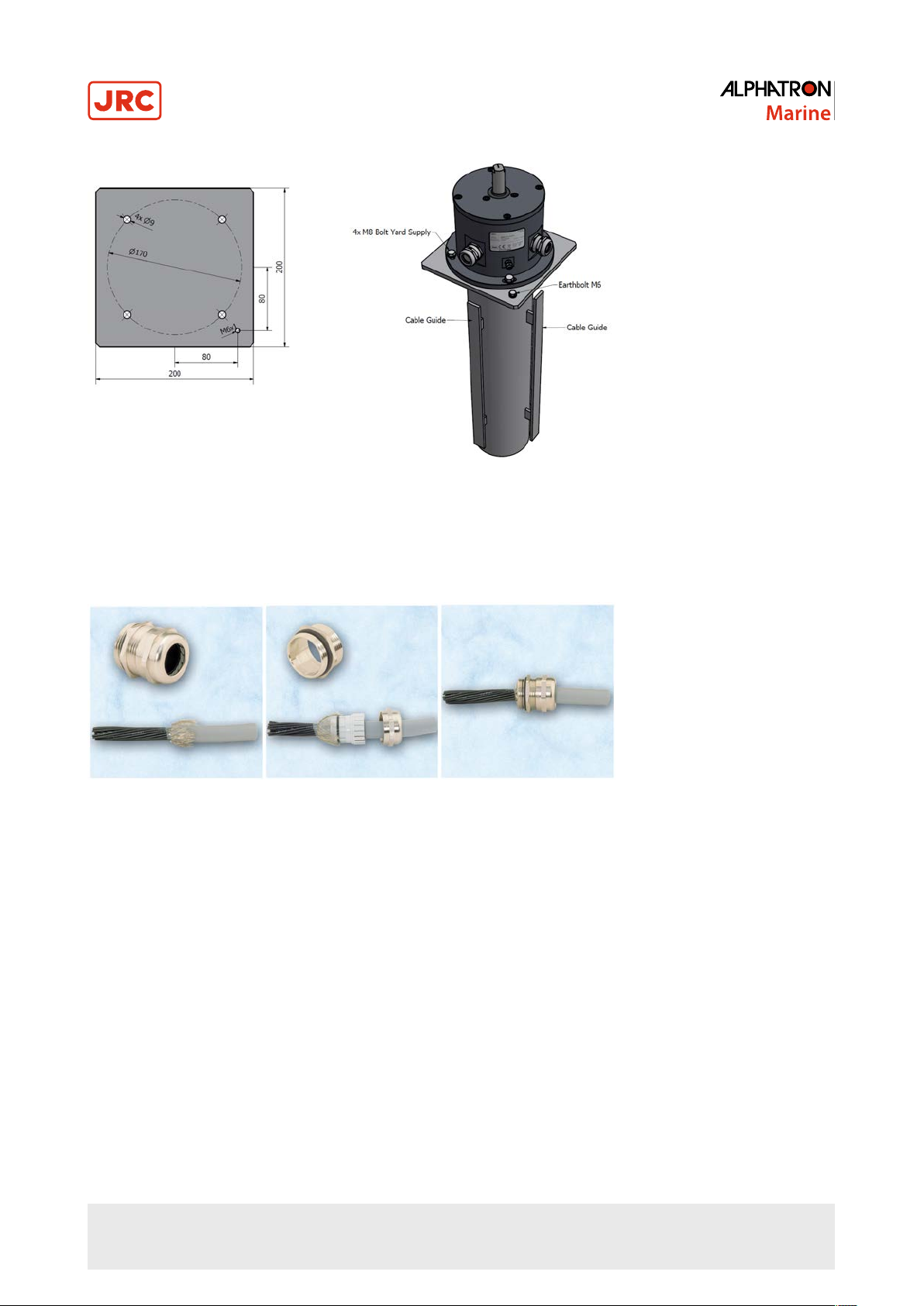
Figure 3: Example of a Foundation
Cables
Only screened cables should be used. The screen must be connected to the cable glands according to Figure 4: Using
Cable Glands on page 11.
Figure 4: Using Cable Glands
Installing the Linkage Transmission
The Linkage Transmission is delivered with all necessary parts except for the RFU LT TUBE. This part is yard delivery.
The yard should determine the proper length and weld one nut with left threat to one side and one nut with right threat on
the other side.
When the Linkage Transmission is used, the angle of the rods should be exactly 90 degrees at a rudder angle of 0
degrees. The distance d2 from the center of the rudder to the ball and socket joint should be exactly the same as the
distance d1 between center of the rudder feedback axle and the corresponding ball and socket joint, see Figure 5:
Rudder Example with Linkage Transmission (Top View) on page 12.
11 | Installation Instructions
Page 12
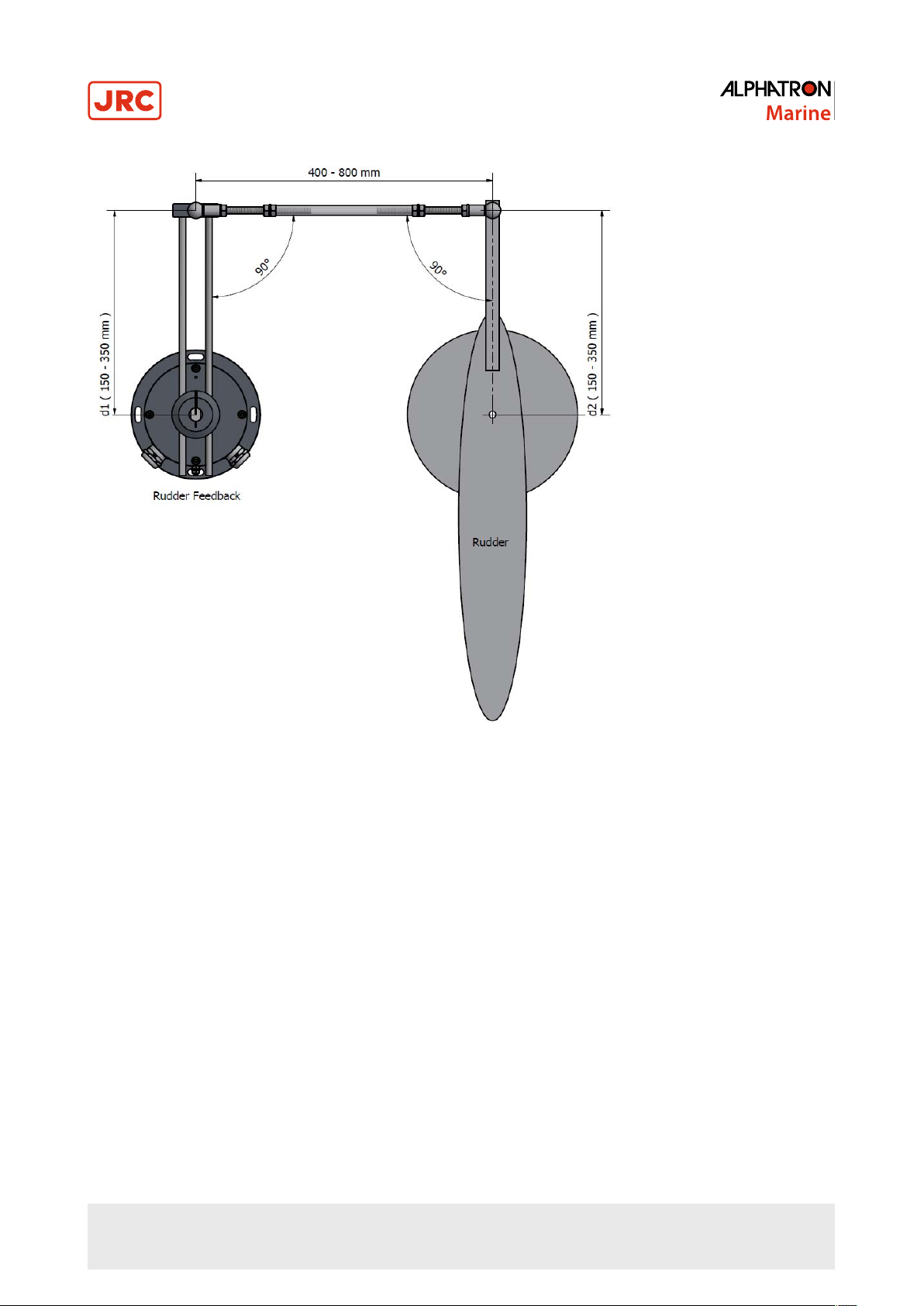
Figure 5: Rudder Example with Linkage Transmission (Top View)
Installing the Chain Transmission
The Chain Transmission is delivered complete with a sprocket with 25 teeth (Rudder Feedback Unit side) and a sprocket
with 28 teeth (rudder side), and parts to create the appropriate tension. When the Chain Transmission is used, the
Rudder Feedback Unit can be placed in any direction compared to the rudder as long as it is easy accessible for
installation and maintenance.
12 | Installation Instructions
Page 13
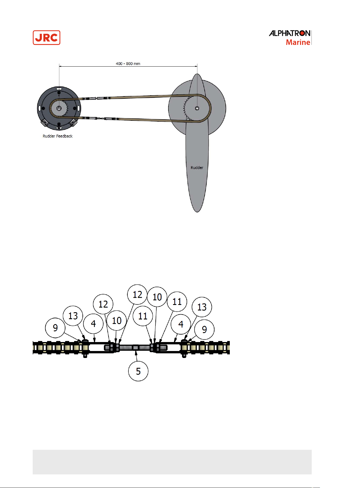
Figure 6: Rudder Example with Chain Transmission (Top View)
The chain of the Chain Transmission is delivered with a total length of 2 meters, divided in a short and a long part. The
short part has to be installed at the side of the Rudder Feedback Unit. The long part can be shortened by removing links
to create the desired length.
The tension of the chain can be changed by rotating the stud bolt (5) with left and right thread, see Figure 7: Stud Bolt on
page 13.
Figure 7: Stud Bolt
The proper tension (100 N) is reached when compression spring (6) is almost completely compressed.
13 | Installation Instructions
Page 14

Figure 8: Compression Spring
After adjusting, nuts (11) and (12) must be secured, see Figure 7: Stud Bolt on page 13.
1.1.4 Module Electric Connections
The Rudder Feedback Unit needs to be opened to connect the wires, see Opening Rudder Feedback Unit MD on page
14 and Opening Rudder Feedback Unit HD on page 16.
For electric connections, see Figure 19: Connection Diagram Rudder Feedback Unit MD on page 28 and Figure 20:
Connection Diagram Rudder Feedback Unit HD on page 29.
1.1.4.1 Opening Rudder Feedback Unit MD
The Rudder Feedback Unit MD needs to be opened to connect the wires.
1. Remove the four outer screws on top of the Rudder Feedback Unit MD, see Figure 9: Rudder Feedback Unit MD
Four Outer Screws on page 14.
INFO:
Figure 9: Rudder Feedback Unit MD Four Outer Screws
2. Gently remove the top part of the Rudder Feedback Unit MD.
14 | Installation Instructions
Page 15

INFO:
Figure 10: Removing Rudder Feedback Unit MD Top
3. Disconnect the 2 connectors and the earth connection.
The Rudder Feedback Unit MD is now open for connection of the wires according to Figure 19: Connection Diagram
Rudder Feedback Unit MD on page 28.
Figure 11: Rudder Feedback Unit MD Electric Connections
When the connections have been made, replace the connectors and close the Rudder Feedback Unit MD. Pay attention
to the O-ring. The red zero position marking should be in the opposite direction of the earth stud.
To close the Rudder Feedback Unit MD, tighten the 4 bolts with 11 Nm.
15 | Installation Instructions
Page 16

1.1.4.1.1 Adjusting Potentiometers
Adjusting the Potentiometers
The potentiometers are aligned in the factory. The middle position of the potentiometers corresponds with the mark on
top of the axle and the red dot on top of the Rudder Feedback Unit MD. When further adjustment is to be made, this has
to be done in the equipment connected to the Rudder Feedback Unit MD.
1.1.4.2 Opening Rudder Feedback Unit HD
The Rudder Feedback Unit HD needs to be opened to connect the wires.
1. Remove the 10 screws of the front hatch, see Figure 12: Rudder Feedback Unit HD Ten Front Hatch Screws on page
16.
INFO:
Figure 12: Rudder Feedback Unit HD Ten Front Hatch Screws
2. Remove the front hatch of the Rudder Feedback Unit HD.
The Rudder Feedback Unit HD is now open for connection of the wires according to Figure 20: Connection Diagram
Rudder Feedback Unit HD on page 29.
16 | Installation Instructions
Page 17

Figure 13: Rudder Feedback Unit HD Electric Connections
When the connections have been made, close the front hatch of the Rudder Feedback Unit HD. When replacing the
screws, first apply the middle top and the middle bottom screw of the hatch and torque to 6,5 Nm.
After this, all other screws can be replaced and torqued to 6,5 Nm.
1.1.4.2.1 Adjusting Limit Switches and Potentiometers
Adjusting the Limit Switches
When adjustment of the limit switches of the Rudder Feedback Unit HD is needed, use an Allen key to loosen the
corresponding cam and adjust it.
After adjustment, tighten the screw again to secure it. See Figure 14: Rudder Feedback Unit HD Limit Switches on page
18 for information on which limit switch is connected to which system and direction.
17 | Installation Instructions
Page 18

Figure 14: Rudder Feedback Unit HD Limit Switches
Adjusting the Potentiometers
The potentiometers are aligned in the factory. The middle position of the potentiometers corresponds with the mark on
top of the axle and the red dot on top of the Rudder Feedback Unit HD. When further adjustment is to be made, this has
to be done in the equipment connected to the Rudder Feedback Unit HD.
1.1.5 Cable
Use the following connection cables:
Name Specification Shield (Y/N) Norm
Potentiometer signal 3 x 1.5 mm
Limit switches 4 x 1.5 mm
Table 3: Connection Cables
2
2
Y
Y
1.1.6 Grounding Modules
To function properly, the Rudder Feedback Unit must be grounded to the ship’s mass.
For this purpose, the Rudder Feedback Unit has a grounding bolt. Connect the grounding bolt to the ship’s mass with a
low impedance connection.
18 | Installation Instructions
Page 19

2 Operation
I Operating the Rudder Feedback Unit
The Rudder Feedback Unit can be used in a rudder angle indicator system and as a part of the control loop in a steering
control system. The output can be connected to an Analog Interface Mk.2. There are two types of rudder feedback units
available: Rudder Feedback Unit MD and Rudder Feedback Unit HD.
The Rudder Feedback Unit MD is medium in size. It is equipped with a dual potentiometer (2 x
the rudder angle to 2 different systems. There are no limit witches present in the Rudder Feedback Unit MD.
The Rudder Feedback Unit HD is larger in size. It is equipped with a dual potentiometer (2 x
rudder angle to 2 different systems. The Rudder Feedback Unit HD has two sets of limit switches.
There are two types of transmissions to choose from:
• RFU Linkage Transmission
• RFU Chain Transmission
The Rudder Feedback Unit MD and the Rudder Feedback Unit HD can each be equipped with either the RFU Chain
Transmission or the RFU Linkage Transmission.
Limit Switches
The Rudder Feedback Unit HD is equipped with limit switches. There are two sets of limit switches; two for port side and
two for starboard. The function of the limit switch is to open its contact once a certain position on the rudder feedback
axle is reached. Utilizing this contact signal from the limit switch, the limit switch can be used to prevent the rudder from
moving further than a predefined angle or to indicate that the rudder has reached its maximum position.
Note The limit switches need to be physically set. Each limit switch has an adjustment screw by which the limit
switch can be set. The adjustment screw can easily be operated when the hatch of the RFU HD is removed.
Note The limit switch itself does not start or stop the rudder. The limit switch simply opens its contact at
certain angle of the rudder feedback axle. It is up to third party systems to use the contact of the limit switch for
controlling the rudder.
RFU Chain Transmission
The principle of the RFU Chain Transmission is quite straight forward. The Rudder Feedback Unit and the rudder are
connected via a chain. The movement (turning) of the rudder is transferred to the Rudder Feedback Unit via the chain.
The potentiometer of the Rudder Feedback Unit translates that movement into a potentiometer output signal. It is up
to other systems to pick up the signal from the Rudder Feedback Unit and translate it in readable values for ship’s
personnel.
RFU Linkage Transmission
The principle of the RFU Linkage Transmission is that the Rudder Feedback Unit and the rudder itself are connected
via a linkage system. The movement (turning) of the rudder is transferred to the Rudder Feedback Unit via the linkage
system. At the Rudder Feedback Unit, the linkage system will turn the axle of the Rudder Feedback Unit. And so, when
the axle of the Rudder Feedback Unit turns, the output of the potentiometer will change, and with that, the reading of
the rudder angle. Depending on how the limit switches are set, turning the axle the limit switches will in turn open their
contacts.
Important Notes
Any dead-band setting regarding the Rudder Feedback Unit needs to be set in the device that receives the potentiometer
signals from the Rudder Feedback Unit. Dead-band settings cannot be made in the Rudder Feedback Unit itself.
As long as all parts of the Rudder Feedback Unit are functioning properly, no calibration of the Rudder Feedback Unit, or
any of its parts, is needed. If any of the rudder readings are off and the potentiometer signal from the Rudder Feedback
Unit is OK, then calibration of the rudder readings needs to be done in the device that receives the potentiometer signals
from the Rudder Feedback Unit.
• WARNING
• The axle of the Rudder Feedback Unit has to be zeroed before the rudder feedback unit can be operated.
Damage to the rudder feedback unit, or any of its components, can occur when the axle is not properly
2KΩ)
which can transfer
2KΩ)
which can transfer the
19 | Operation
Page 20

zeroed. Moreover, without zeroing the axle the rudder readings can be completely wrong and so endanger
ships operation and its personnel.
The maximum angle that the axle (and the attached potentiometer) of the Rudder Feedback Unit can turn, is measured
from the zero position marking. The zero position marking is listed as a red dot on the top of the Rudder Feedback Unit.
When the axle is aligned with the zero position marking, the axle is able to rotate 135 degrees both ways.
Note
• WARNING
• The maximum angle (135 degrees) of the Rudder Feedback Unit may not be exceeded, since this will
compromise the accuracy of the potentiometer output.
20 | Operation
Page 21

3 Maintenance
• CAUTION
• This product contains no operator serviceable parts. Service and repair shall only be carried out by personnel
trained and certified by ALPHATRON MARINE.
Maintenance and repair of the Rudder Feedback Unit should only be performed by personnel that is familiar with the
Alphatron Rudder Feedback Unit.
• CAUTION
• When cleaning the surface, do not use any organic solvent such as thinner or benzine. Otherwise, the paint
and markings on the surface may get damaged. For cleaning the surface, remove the dust and debris and
wipe with a clean dry cloth.
3.1 Rudder Feedback Unit Maintenance
Before starting maintenance on the Rudder Feedback Unit, make sure the rudder is securely chained in its zero position.
Note
• CAUTION
• For safe and reliable operation of the Rudder Feedback Unit, use only specified Alphatron parts.
3.1.1 RFU Chain Transmission Maintenance
The chain used on the Rudder Feedback Unit does not need lubrication. The chain is lube-free due to its plastic rollers.
The plastic of these rollers will automatically lubricate the chain and the sprockets it runs over.
Yearly maintenance tasks:
1. Check if the mounting bolts of the Rudder Feedback Unit are still properly fastened.
2. Check if the screws of the feedback sprocket, i.e. the screws that fasten the sprocket to the axle, are properly
fastened.
INFO: If the screws are loose, apply new Loctite 243 before fastening the screws.
3. Check if the screws of the rudder sprocket, i.e. the screws that fasten the sprocket to the axle, are properly fastened.
INFO: If the screws are loose, apply new Loctite 243 before fastening the screws.
4. Check if the screws and bolts of the chain connection (tensioner) are properly fastened.
INFO: If the screws are loose, apply new Loctite 243 before fastening the screws.
5. Check if the screws and bolts of the chain connection (spring) are properly fastened.
INFO: If the screws are loose, apply new Loctite 243 before fastening the screws.
6. Check the chain connection for any damage and wear.
7. Check the teeth of the feedback sprocket for any damage and wear.
8. Check the teeth of the rudder sprocket for any damage and wear.
9. Check the backlash of the chain part.
3.1.2 RFU Linkage Transmission Maintenance
Yearly maintenance tasks:
1. Check if all screws and bolts are properly fastened.
2. Check if all joints are still greased properly.
3. Check if the 90 degrees angle of the rod still exists.
21 | Maintenance
Page 22

4 Appendix A
Appendix A contains:
1. Specifications on page 22
2. Mechanical Drawings on page 23
3. Electric Diagrams on page 27
4. Thales Certificates on page 30
4.1 Specifications
4.1.1 Specifications Rudder Feedback Unit MD/HD
Box Contents upon Delivery
Rudder Feedback Unit MD 3109.0196
Rudder Feedback Unit HD 3109.0194
Physical Dimensions
Dimensions (WxH)
Weight
Operating Conditions
Operating temperature -25° C to +55° C
Operating humidity Up to 95% (at 40° C)
Storage temperature -25° C to +70° C
Storage humidity Up to 95% (at 40° C)
IP rating IP56
Compass safe distance Std: 10 cm / Steering: 10 cm
MD: 190x173 mm (7.48x6.81")
HD: 190x283 mm (6.30x11.14")
MD: 4.2 kg (9.26 lbs)
HD: 6 kg (13.23 lbs)
Environmental according to DNV 2.4 table 2.1
Temperature Class D
Humidity Class B
Vibration Class A
EMC compatibility Class B
Enclosure Class C
Analog Signals
Potentiometer 1 2 kOhm 3-wire
Potentiometer 2 2 kOhm 3-wire
Analog Contacts (HD version only)
Contact rudder PS 2 pcs NC contacts (max. 3 A-30 V DC/
Contact rudder SB 2 pcs NC contacts (max. 3 A-30 V DC/
Norms/Standards
IEC 60945 (2002) Incl. IEC 60945 Corrigendum 1 (2008)
Standard DNV 2.4 Det Norske Veritas
IEC 61162 series NMEA Definitions
AC1)
AC1)
22 | Appendix A
Available Accessories
RFU Linkage Transmission 3109.0198
RFU Chain Transmission 3109.0200
Page 23

4.2 Mechanical Drawings
4.2.1 Mechanical Drawing Rudder Feedback Unit MD
Figure 15: Mechanical Drawing Rudder Feedback Unit MD
23 | Appendix A
Page 24

4.2.2 Mechanical Drawing Rudder Feedback Unit HD
Figure 16: Mechanical Drawing Rudder Feedback Unit HD
24 | Appendix A
Page 25

4.2.3 Mechanical Drawing RFU Linkage Transmission
Figure 17: Mechanical Drawing RFU Linkage Transmission
25 | Appendix A
Page 26

4.2.4 Mechanical Drawing RFU Chain Transmission
Figure 18: Mechanical Drawing RFU Chain Transmission
26 | Appendix A
Page 27

4.3 Electric Diagrams
The cable diagrams and connection diagrams illustrate the connections to hardware, power and other equipment.
27 | Appendix A
Page 28
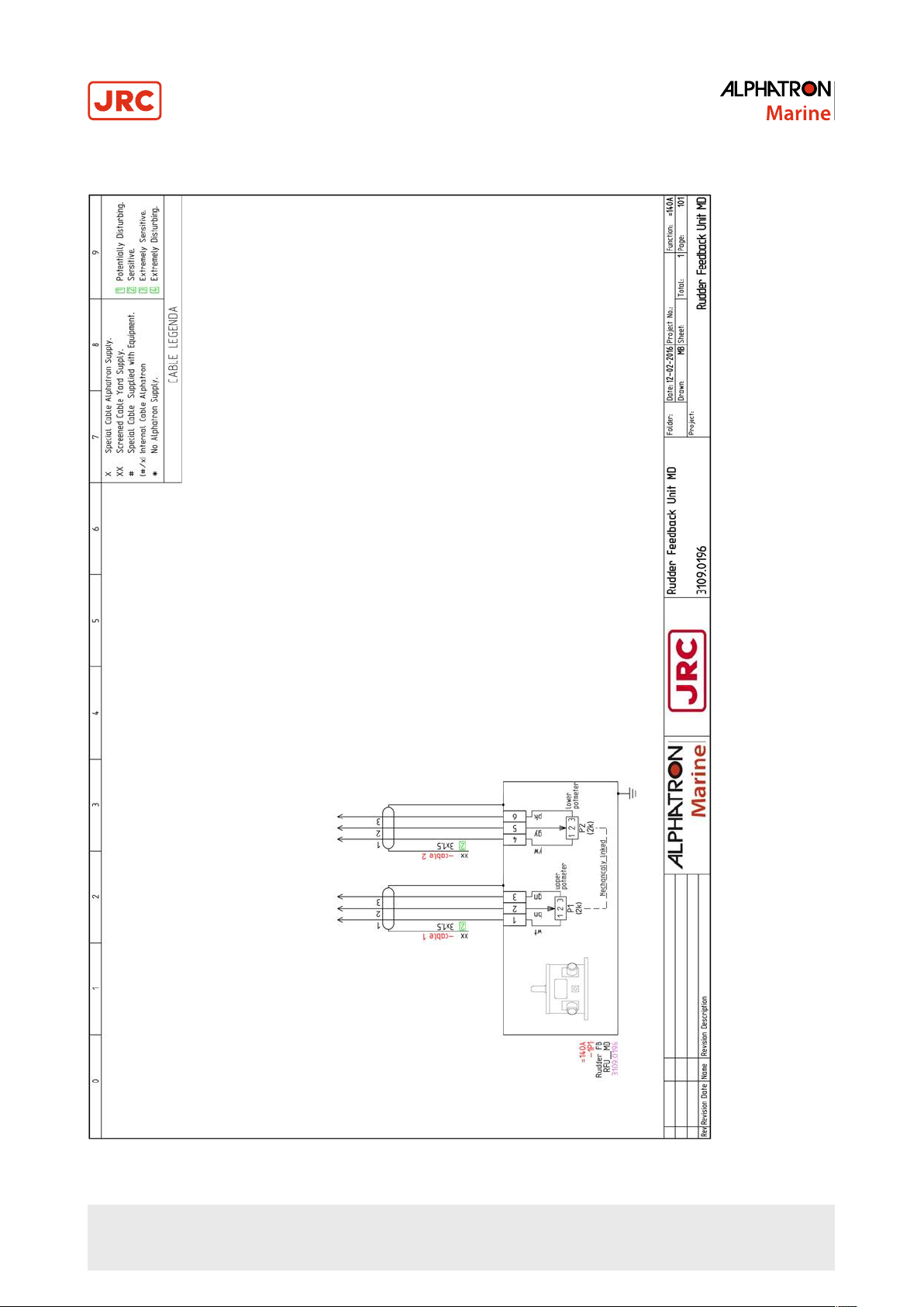
4.3.1 Connection Diagram Rudder Feedback Unit MD
Figure 19: Connection Diagram Rudder Feedback Unit MD
28 | Appendix A
Page 29

4.3.2 Connection Diagram Rudder Feedback Unit HD
Figure 20: Connection Diagram Rudder Feedback Unit HD
29 | Appendix A
Page 30

4.4 Thales Certificates
4.4.1 Thales Certificate Rudder Feedback Unit MD
Figure 21: Thales Certificate Rudder Feedback Unit MD
30 | Appendix A
Page 31

4.4.2 Thales Certificate Rudder Feedback Unit HD
Figure 22: Thales Certificate Rudder Feedback Unit HD
31 | Appendix A
Page 32
5 Appendix B
5.1 ISO 9001 Certificate Alphatron Marine R&D
Figure 23: ISO 9001 Certificate Alphatron Marine R&D
32 | Appendix B
Page 33

6 Appendix C
6.1 EC Declaration of Conformity
Figure 24: EC Declaration of Conformity Rudder Feedback Unit MD/HD
33 | Appendix C
Page 34

All over the world,
close to the customer
JRC/Alphatron Marine
Schaardijk 23 (harbor 115)
3063 NH Rotterdam
The Netherlands
T +31 10 453 4000 Document : Installation and Operation Manual
F +31 10 453 4010 Project no. : Rudder Feedback Unit MD/HD
service@alphatronmarine.com Version : V1.0
www.jrc.am
The information in this document is subject to change without notice and
does not represent a commitment on the part of Alphatron Marine B.V.
©
All rights reserved Alphatron Marine B.V.
Centers of Excellence
Houston, Rotterdam, Singapore, Tokyo
 Loading...