

Page 1
Mode Switch 3 Pos
Operation Manual
www.alphatronmarine.com
Page 2

2 | Preface
Contents
Preface ..................................................................................................................................................... 3
Revision History ................................................................................................................................... 4
Glossary ............................................................................................................................................... 5
Abbreviations ................................................................................................................................... 5
Definitions ........................................................................................................................................ 5
Safety Information ................................................................................................................................... 6
Warranty ................................................................................................................................................. 7
Introduction ............................................................................................................................................. 8
Switching control mode .......................................................................................................................... 9
NFU mode ............................................................................................................................................ 9
MAN mode ........................................................................................................................................ 10
AUTO mode ....................................................................................................................................... 10
Alarm handling ...................................................................................................................................... 11
Dimming ................................................................................................................................................ 11
Alarm speaker and lamp test ................................................................................................................ 12
Page 3

3 | Preface
Preface
The Alphatron AlphaPilot MFM system is a type approved heading control system, designed to fit
vessels of any size, including high speed crafts.
The Mode Switch 3 Pos is part of the AlphaPilot MFM system and is used to select the steering
control mode.
Redundancy is achieved by using a 2 separate CAN busses (1 for manual FU steering and 1 for
automatic steering) and hardwired contacts (from the NFU Tiller directly to the steering control
valves).
Switching from automatic steering to manual FU steering (and vice versa) is only possible by changing
the position of the Mode Switch.
• Thoroughly read this operation manual before operating the equipment.
• We recommend keeping this manual nearby the equipment to ensure ready access to it.
Page 4

4 | Preface
Revision History
Revision
No.
Date
Description
Author
1.0
18-04-2018
First release
J. Kreeft
Page 5

5 | Preface
Glossary
The glossary contains a list of abbreviations and a list of definitions.
Abbreviations
Abbreviations as used in this manual are explained in the table below.
FU
Follow-Up
MAN
Manual
NFU
Non-Follow-Up
Definitions
The meaning of standard definitions as used in this manual are explained in the table below.
Alarm
Audio and visual signal announcing a condition requiring attention.
The audio continues until acknowledged. The acoustic noise pressure
of the alarm is at least 75 dBA but not greater than 85 dBA at a
distance of 1 m (IEC 60945). The visual indication continues until the
alarm condition is removed.
AlphaPilot MFM
Alphatron brand name for the heading control system
Autopilot
A Heading Control System.
Indication
Visual display of any message to the user which may be accompanied
by a low intensity acoustic signal to gain attention.
Steering mode selector
A switch provided for the selection of manual steering modes and
automatic steering devices.
Tiller
A device that is used to turn the rudder, which then steers the boat.
Page 6

6 | Safety Information
Safety Information
The signal words DANGER, WARNING and CAUTION used in this manual indicate the degree of
hazard that may be encountered by the user. These words are defined as follows:
DANGER
Indicates a hazardous situation which, if not avoided, will result in death
or serious injury. This signal word is limited to the most extreme
situations.
WARNING
Indicates a hazardous situation which, if not avoided, could result in death
or serious injury.
CAUTION
Indicates a hazardous situation which, if not avoided, could result in minor
or moderate injury.
The signal word NOTICE used in this manual indicates information considered important but not
related to injury. It is typically used to prevent damage to equipment or property.
To safely operate this system, the following DANGERS, WARNINGS, and CAUTIONS must be adhered
to. Failure to comply with the precautions or with specific dangers, warnings, and cautions elsewhere
in this manual violates safety standards of design, manufacture, and intended use of the equipment.
ALPHATRON MARINE assumes no liability for the customer's failure to comply with these
requirements.
WARNING
Do not disassemble or modify the equipment. Otherwise, it may cause a
fire, or you may suffer an electrical shock.
WARNING
Immediately turn off the power and disconnect the power supply cable if
the equipment is generating any smoke or odour or is overheated.
Immediately inform your local service agent of the symptom to have it
repaired. Prolonged equipment operation under such a condition can
cause a fire or electric shock.
WARNING
Do not place a container containing liquid on the equipment. Otherwise, it
may cause a fire, or you may suffer an electrical shock if knocked over.
WARNING
When unplugging the instrument, be sure to remove the cord terminal
correctly. If the cord is pulled, the cord may get damaged resulting in a fire
or an electrical shock.
Page 7

7 | Warranty
Warranty
To not to adversely affect the warranty, the following notices must be adhered to.
NOTICE
Operating personnel must not remove equipment covers. Only personnel trained
and certified by ALPHATRON MARINE must make component replacement and
internal adjustment.
NOTICE
Do not disassemble or modify the equipment. Failure to observe this instruction
may cause equipment failure, and it will void the warranty.
NOTICE
Any modification to this equipment without prior written permission from
ALPHATRON MARINE will void the warranty.
NOTICE
Installation of this product shall only be done by a certified installation company
approved by either ALPHATRON MARINE or by an official ALPHATRON MARINE
distributor. Acting otherwise will void the warranty.
NOTICE
This product contains no operator serviceable parts. Service and repair shall only be
carried out by personnel trained and certified by ALPHATRON MARINE.
NOTICE
Do not place a container containing liquid on the equipment. The equipment can be
damaged if knocked over.
NOTICE
When cleaning the surface, do not use any organic solvent such as thinner or
benzine. Otherwise, the paint and markings on the surface may get damaged. For
cleaning the surface, remove the dust and debris and wipe with a clean dry cloth.
Page 8

8 | Introduction
Introduction
The Mode Switch 3 Pos is part of the AlphaPilot MFM system and is used to select the steering
control mode. The Mode Switch 3 Pos is typically used in combination with an AlphaPilot MFM
control unit.
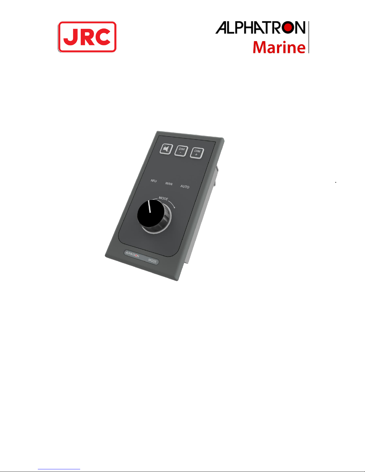
The Mode Switch 3 Pos has 1 rotary switch knob and 3 buttons:
- The alarm speaker button will illuminate when there is an alarm. The button is used to mute
the speakers of the Mode Switch 3 Pos and interconnected modules.
- Buttons DIM - and DIM + are used to control the brightness level of the Mode Switch 3 Pos
and interconnected modules.
- The rotary switch knob is used to select the steering control mode.
Figure 1: Mode Switch 3 Pos
Page 9

9 | Switching control mode
Switching control mode
The rotary switch knob is used to select the steering control mode NFU, MAN or AUTO.
In case of an emergency, always switch the Mode Switch 3 Pos to the position NFU!
NFU mode
Control mode NFU is for emergency steering.
This mode is sometimes called ‘EMERGENCY NFU’ or ‘NFU DIRECT’. In this mode, the NFU Tiller is
hardwired to the steering gear control valves. Manual steering or automatic steering control is not
allowed when the Mode Switch is in position NFU.
Procedure:
Switch to position NFU to enable NFU control. The control mode indicator NFU will illuminate,
meaning that this mode is enabled (see Figure 2).
Figure 2: NFU mode
Figure 4: AUTO mode
Figure 3: MAN mode
Page 10

10 | Switching control mode
MAN mode
Control mode MAN is for manual FU steering.
Procedure:
Before switching to position MAN, make sure that the Handwheel, or FU Tiller at conning position
is in a neutral position!
Switch to position MAN to enable manual FU steering. The control mode indicator MAN will
illuminate, meaning that this mode is enabled (see Figure 3 on page 9). When switched to position
MAN, the Handwheel is selected by default, if applicable. If a Handwheel is not available, the FU
Tiller at conning position is selected by default. While the Mode Switch is in position MAN, it is
possible to handover control to other steering modules (e.g. Handwheel or FU Tiller).
In case of an emergency, always switch the Mode Switch 3 Pos to the position NFU!
AUTO mode
Control mode AUTO is for automatic steering.
Procedure:
Switch to position AUTO to enable automatic steering. The control mode indicator AUTO will
illuminate, meaning that this mode is enabled (see Figure 4 on page 9). When switched to position
AUTO, the AlphaPilot MFM control unit at conning position is selected by default. While the Mode
Switch is in position AUTO, it is possible to handover control to other steering modules (e.g. FU Tiller
ROT or AlphaPilot MFM control unit).
In case of an emergency, always switch the Mode Switch 3 Pos to the position NFU!
Page 11

11 | Alarm handling
Alarm handling
The alarm speaker button is only illuminated when there is an internal alarm. When an alarm occurs,
the alarm speaker button will flash in an uninterrupted sequence, and the speaker will beep in an
uninterrupted sequence.
The alarm speaker can be muted via the alarm speaker button.
When the alarm (is read and) acknowledged on the AlphaPilot MFM control unit, then the
illumination will be constant, and the speaker will be muted (if not muted already via the Mode
Switch). When the alarm is accepted (e.g. problem solved), then the illumination on the alarm
speaker button will turn off.
When the non-illuminated alarm speaker button is pushed, the speaker produces 4 short successive
beeps to indicate that the operation is not valid.
Dimming
Buttons DIM - and DIM + are always illuminated (dimmed to a pre-set brightness level) and control is
always allowed.
Push the button DIM - or DIM + to simultaneously adjust the brightness level of all indicators on the
Mode Switch 3 Pos and interconnected modules.
Note that the ring around the rotary switch knob is always illuminated (dimmed to a pre-set
brightness level) as well.
Figure 5: Alarm
active
Page 12

12 | Alarm speaker and lamp test
Alarm speaker and lamp test
Simultaneously push and hold buttons DIM - and DIM + to test the alarm speaker and the indicators;
The alarm speaker will beep continuously and all indicators (buttons, control mode indicators, and
ring around the rotary switch knob) will illuminate continuously, until the buttons are released.
 Loading...